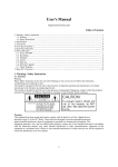
1
User's Manual
Digital Hard Disk Recorder
1. Warning / Safety Instruction
1.1. Warning
Warning
Please follow instruction to prevent any kind of damage or loss. If you do not follow this instruction,
it might bring severe damage or loss.
The symbol is intended to alert the user to the presence of important operating and maintenance (servicing)
instructions in the literature accompanying the unit.
The symbol is intended to alert the user to the presence of uninsulated "dangerous voltage" within the product's
enclosure that may be of sufficient magnitude to constitute a risk of electric shock to persons.
Warning
This equipment has been tested and found to comply with the limits for a Class A digital device,
pursuant to part 15 of the FCC Rules. These limits are designed to provide reasonable protection
against harmful interference when the equipment is operated in a commercial environment. This
equipment generates, uses, and can radiate radio frequency energy and, if not installed and used in
accordance with the instruction manual, may cause harmful interference to radio communications.
Operation of this equipment in a residential area is likely to cause harmful interference in which case
the user will be required to correct the interference at its own expense.
Caution
Any changes or modifications in construction of this device which are not expressly approved by the
party responsible for compliance could void the user's authority to operate the equipment.
Caution
Danger of explosion, if battery is incorrectly replaced. Replace only with the same or equivalent type.
Warranty will be made void if the product is disassembled or manipulated by the user.
1
User's Manual
1.2. Safety Instructions
1. Read these instructions.
2. Keep these instructions.
3. Heed all warnings.
4. Follow all instructions.
5. Do not use this apparatus near water.
6. Clean only with dry cloth.
7. Do not block any ventilation openings. Install in accordance with the manufacturer’s instructions.
8. Do not install near any heat sources such as radiators, heat registers, stoves, or other apparatus (including
amplifiers) that produce heat.
9. Do not defeat the safety purpose of the polarized or grounding type plug. A polarized plug has two blades
with one wider than the other. A grounding type plug has two blades and a third grounding prong. The wide
blade or the third prong is provided for your safety. If the provided plug does not fit into your outlet, consult
an electrician for replacement of the obsolete outlet.
10.Protect the power cord from being walked on or pinched particularly at plugs, convenience receptacles, and
the point where they exit from the apparatus.
11.Only use attachments/accessories specified by the manufacturer.
12.Use only with the cart, stand, tripod, bracket, or table specified by the manufacturer, or sold with the apparatus.
When a cart is used, use caution when moving the cart/apparatus combination to avoid injury from tip-over.
13.Unplug this apparatus during lightning storms or when unused for long periods of time.
14.Refer all servicing to qualified service personnel. Servicing is required when the apparatus has been damaged
in any way, such as power-supply cord or plug is damaged, liquid has been spilled or objects have fallen into the
apparatus, the apparatus has been exposed to rain or moisture, does not operate normally, or has been dropped.
15.The apparatus shall not be exposed to dripping or splashing and that no objects filled with liquids, such as
vases, shall be placed on the apparatus.
16.The mains plug is used as the disconnect device. The disconnect device shall remain readily operable.
2. Specification
Contents
4ch DVR
Video System
NTSC, PAL Selectable System
Multi-Tasking
Quadplex
Video Input
4CH Composite, BNC
2
User's Manual
Contents
4ch DVR
Video Output
1CH Composite BNC, 1CH VGA
Video Compression
H.264
Semi Triple Streaming
• H.264 : Main Codec for recording
Streaming
• H.264 : Codec for Network Streaming (MAX 120fps/NTSC, 100fps/PAL @
CIF)
• JPEG : Codec for Network Streaming (The resolution, quality and FPS are
same as Main Codec)
Recording Resolution
720x480, 720x240, 360x240 (NTSC) / 720x576, 720x288, 360x288 (PAL)
Recording Quality
4 Levels (Normal, Enhanced, Fine, Super Fine)
Max. Display Speed
120fps (NTSC) 100fps (PAL)
Max. Recording Speed
120fps at Full D1 (NTSC) 100fps at Full D1 (PAL)
Recording Frame
per Second (fps)
1,2,3,4,5,6,8,10,15,30 (NTSC, 10 Steps) 1,2,3,4,5,7,9,13,20,25 (PAL, 10 Steps)
Recording Mode
Schedule, Event (Sensor, Motion Detection),
Manual, Continuous, Continuous+Event
Search Method
Calendar, Event (Sensor, Motion Detection)
Playback Speed
x1, x2, x4, x8, x16, x32, x64, x128, Field by Field (Forward, Reverse)
Slow Playback
x1/4, x1/2 (Forward only)
Sensor Input
4 (NO/NC Selectable)
In-, Output (Relay)
1 (NO/NC), 4 TTL
Audio Input
4 ch
Network
10/100Base-T (Static, DHCP, PPPoE, E-mail), DDNS server available
Motion detection
22x15 (NTSC) / 22x18 (PAL), 8 Level Sensitivity
Hard Disk
Max. 1 EA
Back up
USB(Ver2.0), Network
Water Marking
Still Image Backup
Pan Tilt Zoom
RS-485
Serial Port
RS-232(TTL Level, Console)
System Log
Video Loss, Power On/Off, HDD Full, REC Warring, REC Fail,
Menu Called, Reset HDD Format, Reset SW Upgrade, Email Fail
Language
Korean, English, Japanese, French, Spanish, German,
Polish, Italian, Russian, Slovak, Turkish, Czech
Software Upgrade
Network, USB Memory Stick
Power
Free Voltage (100 - 240VAC, 50Hz/60Hz, 42W) using Adaptor(12VDC)
Dimension
280(W) x 290(D) x 55(H)
Operating Temperature
5°C ~ 40°C
Weight (Net)
3Kg (net)
Table 1. DVR Standard
• Above specification features of the product are subject to change without prior notice.
3
User's Manual
3. Accessories
• DVR
• Power Cable
• PTZ / AUX / ALARM / SENSOR INPUT DSUB-25 CONNECTOR 1EA.
• DVR assembly and other screws
• User's Manual
• Remote Controller (Option)
• Software CD (RAMS_H264, UniPlayer_ H264, QuickInstaller_ H264, MultiViewer_ H264, Manual)
4. Front Key Functions
Figure 1. 4CH DVR Front
1. Numeric button / channel switching button
• Numeric button : This button is to be used for inputting network IP address, password (on dialog box display)
and channel selection on live mode or playback mode.
• MULTI
• 4CH DVR
• LIVE : This is to be used to go back to quad screen after selecting specific channel by using channel
selection button.
• PLAYBACK : This is to be used to go back to quad screen after selecting specific channel by using
channel selection button.
• SEQ
• 4CH DVR : This is to be used for the sequential display of all channels that video input is recognized on
live mode. Pressing "SEQ" button shows sequential screen display per channel. Also it can be used to free
all area from motion detection area setting menu.
2. Function button
• POWER : This is to turn on and off the system power. DVR has Soft-Power solution that when pressing
"Power" button, you're asked to input Password to shut down the power for security reasons. (The prevention
of user's mistake - You can select it from the menu)
4
User's Manual
• LOCK : This is to prevent any unwanted system manipulation by unauthorized personnel. Pressing this key
one time, DVR turns into locking status. Afterward any key touch will call up the password input dialog box.
Key lock will be released only when you input the correct password.
• ZOOM : This is to be used to zoom in, or zoom out the specific display area on live mode.
• FRZ(Freeze) : This is to pause the display screen on live mode. Pressing this key button one more time lets
you go back to previous mode.
• MISC
• MISC(Miscellaneous) : This key supports the missing key buttons that are available on remote controller.
(i.e. NET, OSD, Audio, Mute, HDD, Log)
• SEARCH : This is to search the video data files that are recorded on HDD.
• PTZ(Pan/Tilt/Zoom) : This key button allows you to enter Pan/Tilt/Zoom/Focus mode. Pressing this key
button one more time lets you go back to previous live display mode.
• MENU : This is to initiate the System Configuration Menu. If you are already in progress of several steps
of menu control, this key lets you go back to previous upper menu.
3. Button for Recording Playback
• RECORD : This key button initiates the forced recording except the continuous recording mode. Pressing this
key button makes all live video channels start recording and pressing it one more time stops the recording.
• R.PLAY (Reversed Play) : This is to initiate the reversed playback during forward playback. On PTZ control
mode, this key button is to be used to lower the controlling speed.
• STOP : This key button allows you to stop the playback.
• PLAY : This is a playback start button and it initiates the playback of pre-selected channel, starting file, and/
or audio when it's pressed during live mode. On live mode PAUSE status, this button resumes the playback.
In case of PTZ controlling mode, it can be used to increase the controlling speed. On still image viewing
menu, it is also being used for image back up.
• PAUSE : This key button freezes the playback mode until it's pressed again.
4. Direction selection button
• UP : On menu status, this key button can be used to select the detailed item by moving the cursor upward.
On PTZ controlling status, this key button can be used to move the camera upward, or to near the focus. On
playback mode, this key allows you to switch the channel.
• DOWN : On menu status, this key button can be used to select the detailed item by moving the cursor
downward. On PTZ controlling status, this key button can be used to move the camera downward, or to make
the focus far away. On playback mode, this key allows you to switch the channel.
• LEFT : On menu status, this key button can be used to change the setting value. On PTZ controlling status,
this key button can be used to move the camera left direction, or to make the Zoom wide. On playback mode,
this key allows you to lower the plaback speed.
• RIGHT : On menu status, this key button can be used to change the setting value. On PTZ controlling status,
this key button can be used to move the camera right direction, or to make the Zoom Tele. On playback
mode, this key allows you to increase the plaback speed.
• OK : On menu status, this key is being used to confirm and execute the selected function and on PTZ
controlling mode, it's being used to switch Pan/Tilt mode and Zoom/Focus mode.
5. IR Reception : This is to accept the IR data from the remote controller.
5
User's Manual
6. LED Display
• POWER : It shows red light on when the system is on stand-by mode and green light on when the system
is in operation mode.
• REC : Green light flickering on recording mode.
7. Front USB port : This USB port is to be used to back up the video data, or captured still image from HDD. Also
this USB port supports USB mouse controlling for easy DVR operation with front input location advantage.
5. Rear Panel Fucntions
Figure 2. 4CH DVR REAR PANEL
1. MOUSE
• USB input port to back up video data from HDD.
• By connecting USB mouse, you can control DVR with ease.
2. ETHERNET
• 10/100 Base-T network connection port (RJ-45).
3. EXTENSION PORT
• RS-485 port to connect AUX out control, Alarm control, Sensor connection, RS-232 (TTL Level), PTZ
connection. (DSUB-25 male connector)
4. VGA
• VGA : This port exports the same video output signal under VGA signal standard.
5. AUDIO IN/OUT
• IN : Audio Line Input port.
• OUT : Audio Line Output port.
6. VIDEO IN/OUT
• CAMERA : Camera input port. Input signal is CVBS.
• VIDEO OUT : Video output port. Output signal is CVBS.
7. DC 12V
• DVR power supply port. (DC12V/3.5A)
6
User's Manual
6. Basic Operation
6.1. Power ON/OFF
• Power ON : When connecting power cable, power LED light on front panel of DVR turns to red color and this
means that the DVR is on stand-by mode and ready for power on. At this moment, when pressing power key
button on front DVR, power LED light turns into green color, showing the DVR power is actually on. When
DVR booting process is completed, OSD (On Screen Display) menu is displayed on screen. At the same time,
you can hear the buzzer sound, alerting that DVR booting process is completed. But OSD menu with ON setting
features only will be displayed. Once the OSD menu is displayed on the screen, it means the DVR booting
process is normal. Now the user can manipulate the DVR at his convenience.
• Power OFF : When powering off the DVR system, please press the power key button on front panel of DVR.
Then you will see the password input dialog box pop up for your password input (Default : 111111) to turn
off the DVR system. Afterward the power LED display on front panel of DVR becomes red color, showing
stand-by mode.
6.2. Date Time Setup
This is to input the date time of DVR system. After changing the date time of DVR, you must press OK key button
on date time menu to activate the date time application. (System Menu > Date/Time Setup)
6.3. Password Setup
This is to change the password of DVR system. Password configuration can be made with 4 to 8 digit alphanumeric combination. (System Menu > System Password Setup)
6.4. Network Setup
Select the appropriate network type from the network setup menu. Select the network type among STATIC, DHCP,
PPPoE to fit to the appropriate network environment where the DVR system is installed. (Network setup menu)
6.5. Recording
• You can enter into recording setup and select the details. Firstly select the resolution. Available resolution
choices are 720x480, 720x240, 360x240 (NTSC) and 720x576, 720x288, 360x288 (PAL). Audio recording
option, recording quality per channel are available as well. Especially we have adopted "ALL" concept which
you can control 4 channels at the same time. Recording qualities are Enhanced, Normal, Fine, and Super Fine
(4 options). Recording speed is up to 120 fps (NTSC) and 100 fps (PAL). In this category the user can set up
the individual options per channel, or the same application to all channels at his own convenience. Finally the
user can also select recording condition.
• Recording Condition Setup : Recording conditions are composed of MANUAL, CONTINUOUS, MOTION,
SENSOR, MOTION+SENSOR, SCHEDULE and CONTINUOUS+EVENT. When the recording condition is
met according to selected recording mode, then the red-colored icon on top right corner of each channel on
screen is displayed only when the video signal is available. Whenever the Record button on MANUAL recording
is pressed, recording goes ON/OFF.
6.6. Playback
• Direct Playback by using PLAY button : When pressing PLAY button, DVR starts the playback according to
the playback setting condition of selected channel, playback starting point and audio playback option.
• Audio Playback : In case of running the recorded video data file with audio link included, then the audio plays
back automatically. The decision of audio link can be selected on audio connection menu.
6.7. Search
• Search Mode : DVR provides 3 types of Search Modes.
7
User's Manual
• Calendar Search : For easy search of recorded data, DVR provides the calendar search format.
• Event Search : This shows the recorded data list generated by SENSOR, MOTION and SCHEDULE.
• Captured Still Image Search : This shows the separate list of still images captured during playback.
• Search Method
• Calendar Search : By pressing Search button, 3 different Search modes comes up. Among these 3 modes,
please select Calendar search menu. Calendar search selection calls up the Year, Month, Day window. Once
you select the Year, Month Day, then the hour minute window comes up. Once you select the hour minute,
all channels on this time frame will start playing back.
• Event Search : By pressing Search button, 3 different Search modes comes up. Among these 3 modes, please
select Event search menu. After selecting date, time and channel, list window will come up. Please input the
preferred time frame and channel, and press OK button for playback.
• On Search list, page movement is available by left and right arrow key and for the up/down movement in the
same page, please use up/down arrow key.
6.8. Back up
• USB Memory Stick
• By connecting USB memory stick into USB port, you can back up the data manually. The user can back up
the video data from HDD to USB device by using System setup > Backup menu.
• After connecting USB memory stick to USB port and selecting Backup time selection > Backup start on
Backup menu, it starts back up operation within the capacity of USB memory stick.
• By keeping SimplePlayer program in USB memory stick where the backup video data is located, the user
can execute the playback at any time.
• Network
• By using network from remote site, the user can transfer the video and audio data from DVR HDD to user's
PC for back up.
6.9. Software Upgrade
• By using USB memory stick, the user can upgrade the Ramdisk and Kernel software of DVR.
1. You can download Kernel or Ramdisk file to upgrade.
2. Copy the downloaded file into USB memory stick.
3. Plug USB memory stick into USB port located on front or rear panel of DVR.
4. Select Ramdisk or Kernel file to upgrade from Menu > System Setup > Software Upgrade.
5. The DVR recognizes USB memory stick and starts upgrading automatically. After upgrade, the DVR starts
re-booting.
• By using the PC-Client program (RAMS_H264), the user can upgrade Ramdisk or Kernel software. (See
attached manual on enclosed CD)
6.10. Client Program
• RAMS_H264(Remote Access Monitoring System H.264) : This program enables you to connect to DVR
remotely by network and to monitor live video, to search the recorded data on DVR, and to back up the data
onto user's PC.
8
User's Manual
• UniPlayer_H264 : This program enables you to play the video data files recorded from RAMS, captured files
and backed-up files.
• MultiViewer_H264 : This program enables you to monitor multiple DVRs.
• QuickInstaller_H264 : This program enables you to retrieve the setting parameter data from the DVR by
connecting serial port or network and to save the changed parameter setting value data into DVR.
• Unimap : This program enables you to monitor live video and shows the real-time status of DVR where the
actual cameras' location is indicated on map image.
• MobileViewer : This program enables you to monitor live video and the status of DVR by using mobile devices
like PDA or Smart Phone that support wireless internet connection.
• iPhoneViewer : This program enables you to monitor live video and the status of DVR by using iPhone device.
7. Basic ID / Password
You can register the users up to 14 accounts on top of provided ADMIN, USER_1 ~ USER_5 accounts.
For the first time setup, only ADMIN account has the following default password. The other users' accounts are
to be activated only when you set up each user's password in advance.
• ID : ADMIN
• Password : 111111
9