1
GE Healthcare
Life Sciences
UNICORN™ 6.1
Method Manual
Table of Contents
Table of Contents
1
Introducing the UNICORN Method Editor ........................................................
1.1
1.2
1.3
2
3
4
8
10
12
The UNICORN Method Editor .............................................................................
13
2.1
2.2
The Method Editor ................................................................................................................................
Methods in UNICORN 6.1 ..................................................................................................................
14
20
Create and edit methods ....................................................................................
25
3.1
3.2
3.3
3.3.1
3.3.2
3.4
3.5
3.6
3.7
3.8
3.9
3.10
3.11
26
30
34
35
43
51
63
69
79
81
89
92
94
Working with methods - Overview ...............................................................................................
Create and open methods ...............................................................................................................
Edit methods and phases .................................................................................................................
Edit phase properties ........................................................................................................................
Edit the method outline ...................................................................................................................
Set general method options for the method ...........................................................................
Save methods and phases ...............................................................................................................
Scale or convert methods ................................................................................................................
Print a method .......................................................................................................................................
Predefined methods and phases ..................................................................................................
Fraction collection ................................................................................................................................
Sign methods electronically ............................................................................................................
Import and export methods ............................................................................................................
Scouting ................................................................................................................. 103
4.1
4.2
5
7
About the UNICORN Method Editor ..............................................................................................
About this manual ................................................................................................................................
UNICORN 6.1 user documentation ...............................................................................................
Overview ...................................................................................................................................................
Set up and edit a Scouting scheme .............................................................................................
104
106
Design of Experiments ........................................................................................ 116
5.1
5.2
5.2.1
5.2.2
5.2.3
5.2.4
5.3
5.4
5.4.1
5.4.2
5.4.3
5.4.4
5.4.5
5.4.6
5.4.7
Introduction to Design of Experiments .......................................................................................
Create an experimental design ......................................................................................................
Set up an experimental design ....................................................................................................
Add responses and factors to an experimental design .....................................................
Change design and design settings in a Design of Experiments setup ......................
Divide the DoE runs into several scouting runs ....................................................................
Run a scouting created with DoE ..................................................................................................
Evaluation of Design of Experiments ...........................................................................................
Workflow ................................................................................................................................................
Generate model ..................................................................................................................................
Analyze and evaluate the model - basic analysis ................................................................
Analyze and evaluate the model - extended analysis .......................................................
Edit the model ......................................................................................................................................
Use the model ......................................................................................................................................
Create and print reports ..................................................................................................................
UNICORN 6.1 Method Manual 28-9817-65 AB
117
128
129
138
145
149
155
157
158
160
170
182
190
193
200
3
Table of Contents
6
BufferPro ................................................................................................................ 203
6.1
6.2
6.3
6.3.1
6.3.2
6.3.3
6.4
6.5
6.6
6.7
7
Method queues - overview ..............................................................................................................
Create a method queue .....................................................................................................................
Edit a method queue ...........................................................................................................................
Overview ...................................................................................................................................................
Handling column types ......................................................................................................................
Handling individual columns ...........................................................................................................
Individual column identification ..................................................................................................
Register a new individual column ...............................................................................................
Find an individual column ..............................................................................................................
Edit individual columns ....................................................................................................................
Export and import individual columns .....................................................................................
Print and view individual column information ......................................................................
Column performance .........................................................................................................................
Intelligent Packing of AxiChrom™ columns .............................................................................
242
247
260
261
262
266
268
271
274
276
279
Text edit methods ................................................................................................ 286
9.1
Overview ...................................................................................................................................................
9.1.1
Working with text instructions .....................................................................................................
9.1.2
The Text Instructions pane .............................................................................................................
9.2
Working with methods in the Text Instructions pane ..........................................................
9.2.1
Base instruction ..................................................................................................................................
9.2.2
Working with phases and blocks ................................................................................................
9.2.3
Working with text instructions .....................................................................................................
9.2.4
Method variables ................................................................................................................................
9.3
Specific instructions ............................................................................................................................
9.3.1
Gradients and eluent concentrations ........................................................................................
9.3.2
Alarm instructions ..............................................................................................................................
9.3.3
Watch instructions .............................................................................................................................
9.3.4
Pause or hold a method ..................................................................................................................
9.3.5
Messages and Set marks ................................................................................................................
4
230
231
235
Column Handling .................................................................................................. 241
8.1
8.2
8.3
8.3.1
8.3.2
8.3.3
8.3.4
8.3.5
8.3.6
8.4
8.5
9
204
206
207
208
212
214
216
219
222
226
Method queues ..................................................................................................... 229
7.1
7.2
7.3
8
BufferPro - Overview ...........................................................................................................................
Create a method using BufferPro .................................................................................................
Create and edit BufferPro recipes .................................................................................................
Create and edit a BufferPro recipe .............................................................................................
Rename a BufferPro recipe ............................................................................................................
Delete a BufferPro recipe ................................................................................................................
Print a BufferPro recipe ......................................................................................................................
Calculate buffer composition using BufferPro ........................................................................
Export and import BufferPro recipes ...........................................................................................
Predefined BufferPro recipes ..........................................................................................................
287
288
290
295
296
300
309
315
326
327
330
333
340
343
UNICORN 6.1 Method Manual 28-9817-65 AB
Table of Contents
10 Troubleshooting ................................................................................................... 346
10.1
10.2
Troubleshooting methods ................................................................................................................
System Error Reports ..........................................................................................................................
347
353
Index ....................................................................................................................... 358
UNICORN 6.1 Method Manual 28-9817-65 AB
5
1 Introducing the UNICORN Method Editor
1
Introducing the UNICORN Method
Editor
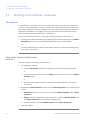
Introduction
This chapter contains:
•
A general introduction to creating methods using the UNICORN software.
•
Information about the user documentation for UNICORN, including an overview of
related documents describing the use of the software.
Software declaration of
conformity
UNICORN 6.1 is technically compatible with all relevant sections of FDA 21 CFR Part 11.
A part 11-system assessment checklist is available on request through the local GEHC
representative.
In this chapter
This chapter contains these sections:
Section
1.1 About the UNICORN Method Editor
See page
8
1.2 About this manual
10
1.3 UNICORN 6.1 user documentation
12
UNICORN 6.1 Method Manual 28-9817-65 AB
7
1 Introducing the UNICORN Method Editor
1.1 About the UNICORN Method Editor
1.1
About the UNICORN Method Editor
Introduction
This section is a brief introduction to creating methods in UNICORN and a description of
the scope of this manual.
What is UNICORN?
UNICORN is a complete software package for:
•
control and supervision of chromatography systems.
•
evaluation and analysis of the results from separation runs.
This manual describes UNICORN 6.1, which is designed for ÄKTA™ avant chromatography
systems. This software version is not compatible with other ÄKTA systems.
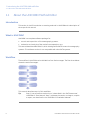
Workflow
The workflow in UNICORN can be divided into four distinct stages. The flow chart below
shows the work flow stages.
1. Create a method
2. Run the method
3. Evaluate the results
4. Compile a report
This manual describes step 1 of this workflow.
Tip:
Step 2, how to perform method runs, is described in the "ÄKTA avant and
UNICORN 6.1 User Manual". Step 3, evaluate the results, and step 4, compile
a report, are described in the "UNICORN 6.1 Evaluation Manual".
8
UNICORN 6.1 Method Manual 28-9817-65 AB
1 Introducing the UNICORN Method Editor
1.1 About the UNICORN Method Editor
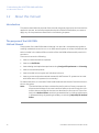
Create a method
A method in UNICORN is a user-defined set of instructions that can be used to run an
entire process on a system, for example a purification run or a column performance
test. A method is comprised of one or several phases which are reusable sets of instructions. Examples of phases are equilibration steps and elution steps.
The UNICORN Method Editor module is a comprehensive tool for creating or editing
phases and methods. UNICORN is delivered with templates for common procedures that
can easily be edited for a specific process. Using the Method Editor it is possible to:
•
build a method from a library of phases.
•
create custom phases.
•
create method queues to run multiple methods on up to three separate systems.
•
keep track of column types or individual columns using the Column Handling tool.
•
design and optimize purification schemes using the Design of Experiments and
Scouting tools.
•
automatically mix and titrate buffers using the BufferPro tool.
etc.
UNICORN 6.1 Method Manual 28-9817-65 AB
9
1 Introducing the UNICORN Method Editor
1.2 About this manual
1.2
About this manual
Introduction
This section describes the purpose of the manual, the general structure and conventions
applied in the text, and some prerequisites that should be fulfilled before you start to
apply any of the procedures described in the following chapters.
The purpose of the UNICORN
Method Manual
The purpose of the UNICORN Method Manual is to provide a comprehensive guide to
creating methods that can be run on an ÄKTA avant system. It covers the features and
tools included in the Method Editor module of the UNICORN software with practical instructions.
The manual covers the following:
•
how to create methods and phases.
•
how to use BufferPro.
•
how to design and optimize experiments using Design of Experiments and Scouting.
•
how to use method queues.
•
how to handle column types and individual columns.
•
how to convert and scale methods created for ÄKTA avant 25 systems to be used
with ÄKTA avant 150 systems (or conversely).
For advanced users, an overview of how to edit methods at the level of individual instructions is also given.
Note:
The Method Manual does not describe the functions of every command in
all panes and dialogs of the user interface. Refer to the online help for information about commands that are not described in this manual. The online
help in the Method Editor module is accessed either by clicking Help buttons
in software dialogs, by pressing the F1 key, or selecting Help:Help for Method
Editor.
10
UNICORN 6.1 Method Manual 28-9817-65 AB
1 Introducing the UNICORN Method Editor
1.2 About this manual
Document structure
Each chapter starts with a brief overview that presents the contents and the headings
for the sections that the chapter contains. Most sections begin with an introduction that
summarizes the content. Some sections are divided into sub-sections, each with an
overview of the contents.
A section is divided into blocks of information with separating lines. The blocks are
identified by a label extending into the margin (such as the label Document Structure
above). This makes it easier for you to quickly scan a page to find the exact topic you
are looking for.
Typographical conventions
Menu commands, field names and other text items from the software are quoted exactly
as they appear on the screen, in a bold italic typeface:
Example: Method Navigator
Search paths are shown in a bold italic typeface with a separating colon between each
level:
Example: Edit:Import:Import Phase... i.e., the menu option Import Phase... in the submenu Import from the Edit-menu.
Controls on the instrument, computer or keyboard keys are shown with a bold, regular
typeface:
Example: Press the Delete key.
Text that the user must either type exactly as shown in the manual, or that UNICORN
displays as a response (not a regular part of the graphic user interface), is represented
by a monotype typeface within quotation marks:
Example: "Connection change"
Prerequisites
The following prerequisites must be fulfilled before you can use this manual the way it
is intended:
•
You need to have a general understanding of how your PC and Windows™ work. In
most cases universal computer functions will not be explained.
•
UNICORN must be installed and configured correctly on your computer.
•
Your user profile and access rights must be set up, and you must be able to log on
to UNICORN and access a database.
•
You need to understand the general concepts of liquid chromatography. Terminology
and functionalities will be explained only when they differ from normal practice.
UNICORN 6.1 Method Manual 28-9817-65 AB
11
1 Introducing the UNICORN Method Editor
1.3 UNICORN 6.1 user documentation
1.3
UNICORN 6.1 user documentation
Introduction
This section describes the user documentation that is delivered with an ÄKTA avant
system.
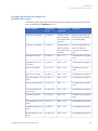
User documentation
The user documentation listed in the table below is available from the Help menu in
UNICORN or on the ÄKTA avant and UNICORN User Documentation CD.
12
Document
Main contents
ÄKTA avant and UNICORN 6.1
Installation Guide
Site preparation, stand-alone installation and test
procedure.
Getting Started with ÄKTA
avant and UNICORN 6.1
System overview and instructions to perform a basic
run.
ÄKTA avant and UNICORN 6.1
User Manual
Instructions for safe handling of the system. Descriptions of components. Information about how to run
and maintain the system.
UNICORN Help
Dialog descriptions for UNICORN (from the Help
menu).
UNICORN 6.1 Method Manual
Overview and detailed descriptions of the method
creation features in UNICORN. Instructions on how
to use the software. Workflow descriptions for
common operations.
UNICORN 6.1 Evaluation Manual
Overview and detailed descriptions of the evaluation
features in UNICORN. Instructions on how to use
the software. Workflow descriptions for common
operations.
UNICORN 6.1 Administration
and Technical Manual
Network setup and complete software installation.
Administration of UNICORN and the UNICORN
database.
UNICORN 6.1 Method Manual 28-9817-65 AB
2 The UNICORN Method Editor
2
The UNICORN Method Editor
About this chapter
This chapter gives an introduction to the Method Editor in UNICORN 6.1. It gives a brief
description of the Method Editor interface and describes the concept of methods in
UNICORN 6.1.
For information about how to create, open and edit methods as well as signing methods
and importing/exporting methods, see Chapter 3 Create and edit methods, on page 25.
In this chapter
This chapter contains the following sections:
Section
See page
2.1 The Method Editor
14
2.2 Methods in UNICORN 6.1
20
UNICORN 6.1 Method Manual 28-9817-65 AB
13
2 The UNICORN Method Editor
2.1 The Method Editor
2.1
The Method Editor
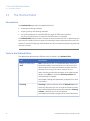
Introduction
The Method Editor provides complete facilities for:
•
creating and editing methods
•
copying, saving and deleting methods
•
converting methods for use with different types of ÄKTA avant systems
(e.g. from an ÄKTA avant 25 system to an ÄKTA avant 150 system)
The Method Editor also provides a number of tools to assist the user in optimizing runs
and a tool for handling column types and individual columns (see below for more information). Functions like signing methods electronically and importing/exporting methods
are also included.
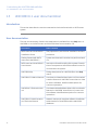
Tools in the Method Editor
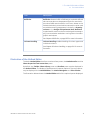
The table below describes the different tools included in the Method Editor.
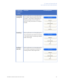
Tool
Description
Design of experiment
(DoE)
DoE is used to find out, in a systematic way, which run
parameters affect a process to be run and how to find
optimal values for these parameters to obtain the best
possible result using a minimum number of runs.
When creating a method and setting up an experimental
design using DoE, an optimized Scouting scheme will
automatically be created.
See Chapter5 Design of Experiments, on page 116 for more
information.
Scouting
Scouting is used to repeat a series of Method runs automatically, where the user can change the values of predetermined variables before starting the method. A Scouting
scheme is defined as part of the method.
See Chapter 4 Scouting, on page 103 for more information.
14
UNICORN 6.1 Method Manual 28-9817-65 AB
2 The UNICORN Method Editor
2.1 The Method Editor
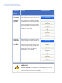
Tool
Description
BufferPro
BufferPro allows a buffer of defined pH, and with defined
salt concentrations to be prepared from four stock solutions (one Buffer stock solution, one Titrant, Water and a
Salt stock solution). pH and salt concentration can be used
as variable scouting parameters included in a Scouting
scheme or in a Design of Experiments (DoE). BufferPro
is optimized for cation and anion exchange chromatography, but can also be used when running other chromatographic techniques.
See Chapter 6 BufferPro, on page 203 for more information.
Column Handling
Column Handling enables handling of column types and
individual columns.
See Chapter 8 Column Handling, on page 241 for more information.
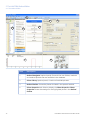
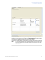
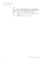
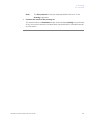
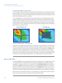
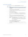
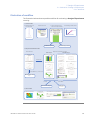
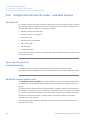
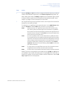
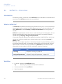
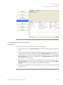
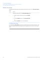
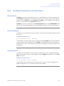
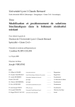
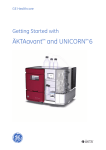
Illustration of the Method Editor
The basic Method Editor interface consists of two panes, the Method outline and the
Phase Properties/Text Instructions pane.
By default, the Toolbar, Phase Library pane and Gradient pane are also displayed in
the Method Editor. The display of these panes is however optional. Two more panes
may be displayed in the Method Editor, the Method Navigator and Flow Scheme.
The illustration below shows the Method Editor with all the optional panes displayed.
UNICORN 6.1 Method Manual 28-9817-65 AB
15
2 The UNICORN Method Editor
2.1 The Method Editor
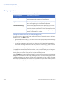
6
5
4
1
3
2
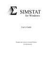
7
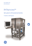
16
8
Area
Description
1
Method Navigator (optional pane): Shows all the user folders, methods
and method queues that are available in the database.
2
Phase Library (optional pane): Contains all available phases.
3
Method Outline: Shows the phases included in the opened method.
4
Phase Properties tab: Select to display the Phase Properties. Phase
Properties shows the settings for the highlighted phase in the Method
Outline.
UNICORN 6.1 Method Manual 28-9817-65 AB
2 The UNICORN Method Editor
2.1 The Method Editor
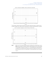
Area
Description
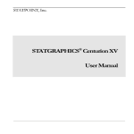
5
Text Instructions tab: Select to display the Text Instructions. Text Instructions shows the method in a text format. The illustration below shows the
Text Instructions pane.
6
Toolbar (optional pane): Shows the toolbar icons.
7
Gradient (optional pane): Shows the programmed gradient and break
points for included phases and blocks.
8
Flow Scheme (optional pane): Illustrates the flow path of the instrument
graphically.
Note:
For detailed information on the Toolbar and the different panes in the Method
Editor, see "Getting Help on the Toolbar and panes in the Method Editor"
below.
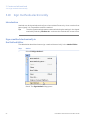
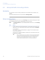
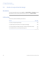
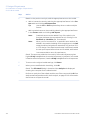
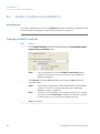
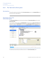
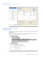
Display optional panes
The optional panes in the Method Editor are displayed by selecting them in the View
menu. To restore the appearance of the Method Editor to display the default panes,
select Restore to Default in the View menu. Then, the Toolbar, Gradient and Phase Library are displayed. The appearance of the optional panes can also be controlled using
the Auto Hide function (see below for more information).
Note:
Settings made by a user are automatically remembered by the software next
time the same user opens the Method Editor.
The illustration below shows the View menu with the default panes selected.
UNICORN 6.1 Method Manual 28-9817-65 AB
17
2 The UNICORN Method Editor
2.1 The Method Editor
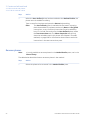
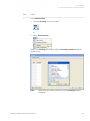
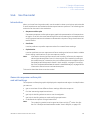
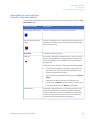
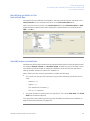
Auto Hide optional panes
The optional panes may either be displayed statically in the position where they open,
or the Auto Hide function can be selected to automatically hide/display the pane when
moving the mouse pointer over the pane.
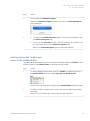
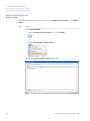
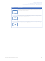
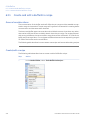
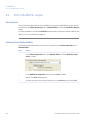
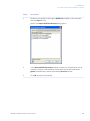
The table below describes how to turn on the Auto Hide function and how to hide/display,
in this example, the Method Navigator pane.
Step
Action
1
If not already displayed, open the Method Navigator in the Method Editor
by selecting View:Method Navigator.
Result: The Method Navigator pane is displayed.
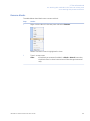
2
To turn on the Auto Hide function, click the vertical pin symbol in the top
righthand corner.
Result: The pin symbol is rotated to horizontal position and a tab named
Method Navigator is displayed to the left.
18
UNICORN 6.1 Method Manual 28-9817-65 AB
2 The UNICORN Method Editor
2.1 The Method Editor
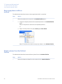
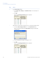
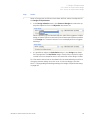
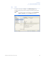
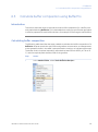
Step
Action
3
Click outside the Method Navigator.
Result: The Method Navigator is hidden and only the Method Navigator
tab is displayed.
4
•
To display the Method Navigator again, move the mouse pointer over
the Method Navigator tab.
•
To turn off the Auto Hide function, click the horizontal pin symbol in the
top righthand corner of the Method Navigator pane.
Result: The Method Navigator pane is displayed statically.
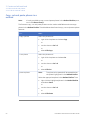
Getting help on the Toolbar and
panes in the Method Editor
The table below describes how to find detailed information about the Toolbar and the
different panes in the Method Editor by opening the Online Help.
Step
Action
1
To display detailed information about the Toolbar and different panes in
the Method Editor interface, select Help:Help For Method Editor.
Result: The online help opens displaying the Method Editor help start page.
2
To display help for a specific pane, click in the pane and press the F1 keyboard key.
Result: The online help page describing that pane is opened.
UNICORN 6.1 Method Manual 28-9817-65 AB
19
2 The UNICORN Method Editor
2.2 Methods in UNICORN 6.1
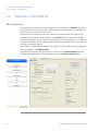
2.2
Methods in UNICORN 6.1
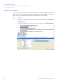
About methods
The program instructions for a chromatography run are defined in a Method. The instructions are specific for each instrument configuration and component set up and follow
certain syntactical and hierarchical rules.
Instructions are combined into blocks. Individual instructions and minor blocks are
combined into the major method blocks, called Phases. Each phase reflects a step in
the chromatography run, for example, equilibration or sample application. A number of
settings are available for each type of phase. By building methods in this way, methods
are easily created and edited.
See Chapter 3 Create and edit methods, on page 25 for information about creating and
editing methods in the Method Editor.
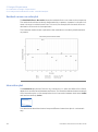
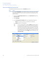
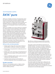
The illustration below shows the phases in a method in the Method Outline and the
corresponding settings for the highlighted phase in the Phase Properties pane.
20
UNICORN 6.1 Method Manual 28-9817-65 AB
2 The UNICORN Method Editor
2.2 Methods in UNICORN 6.1
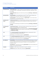
Method structure
A method always starts with the Method Settings phase. This phase contains general
settings that affect the rest of the method (e.g., Column type, Flow rate and Method
Base Unit). If changing Column type, UNICORN will automatically calculate correct settings for volume, flow rate, and pressure limits. Subsequent phases reflect steps included
in the chromatography run.
The figure below shows a method with the different phases in the Method Outline in the
Method Editor.
Working with methods
It is recommended to create and edit methods using Phase Properties. Phases can
easily be dragged-and-dropped into the Method Outline from the Phase Library and
the phases are easily rearranged. Settings for each phase are set in the Phase Properties
pane. When working like this, the text method is automatically built up in the Text Instructions pane and settings for blocks and instructions are updated accordingly.
The illustration below shows the phase properties settings and the text instructions for
the Method Settings phase.
UNICORN 6.1 Method Manual 28-9817-65 AB
21
2 The UNICORN Method Editor
2.2 Methods in UNICORN 6.1
It is possible to use the text editor in Text Instructions to create a phase from scratch
and to edit methods. Instructions are then created/edited one by one. This can be an
option for fine-tuning or optimization of a method. If the text editor is used, Phase
Properties will subsequently only show a list of variables for the phase, as shown in the
following illustration. This can always be restored by clicking on the Restore Phase
Properties button.
Phases that have been edited in the text editor are noted with a blue letter T as shown
in the illustration below.
22
UNICORN 6.1 Method Manual 28-9817-65 AB
2 The UNICORN Method Editor
2.2 Methods in UNICORN 6.1
The phase User Defined is an empty phase designed for text editing methods. Such
phases will only be displayed as a variable list in Phase Properties, and may be saved
in the personal or global phase library for reuse in other methods.
See Chapter 9 Text edit methods, on page 286 for information about text editing methods.
Note:
Do not mix text edited and non text edited phases unless you clearly understand the implications for the entire method of the instructions in the text
edited phases.
UNICORN 6.1 Method Manual 28-9817-65 AB
23
2 The UNICORN Method Editor
2.2 Methods in UNICORN 6.1
Predefined and Empty methods
In UNICORN, a number of Predefined methods for different separation techniques and
maintenance applications (e.g., preparation and cleaning of the system and columns)
are supplied. When creating new methods, it is possible to use one of the Predefined
methods or create a user defined method starting with an Empty method. The phase
Method Settings is mandatory in all methods.
See Chapter 3 Create and edit methods, on page 25 for information about how to create
new methods.
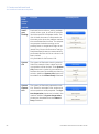
The table below gives a general description of Predefined and Empty methods.
Method
Description
Predefined
Predefined methods include a number of relevant phases
appropriate for the purification or maintenance to be
performed. You may use the predefined methods as they
are, or with adjusted settings as needed.
See Section Section 3.8 Predefined methods and phases,
on page 81 for descriptions of the Predefined methods
supplied with the software.
Note:
The Predefined methods are included in the
instrument configuration files for each specific
instrument.
Empty
Empty methods include the mandatory phase Method
Settings. Other phases are then added by the user and
settings adjusted as needed.
Predefined phases
UNICORN provides a number of Predefined Phases (e.g., Equilibration, Column CIP and
User Defined) that can be used when building/editing methods in the Method Editor. A
predefined phase contains all necessary instructions to be run (except Method Settings
which is mandatory in all methods, and User Defined that are special phases).
See Section 3.8 Predefined methods and phases, on page 81 for descriptions of the predefined phases supplied with the software. See also Chapter 3 Create and edit methods,
on page 25.
24
UNICORN 6.1 Method Manual 28-9817-65 AB
3 Create and edit methods
3
Create and edit methods
About this chapter
This chapter describes how to create, edit and handle chromatography and maintenance
methods in UNICORN 6.1 using the Phase Properties pane. It also describes overall
method options, how to sign methods electronically, how to print methods, how to
convert and scale methods from one ÄKTA avant system type to another, and how to
import/export methods. Descriptions of the predefined methods and phases supplied
with the software are also included.
Note:
It is recommended to work with phases using the Phase Properties pane.
This chapter does not cover how to edit methods using the Text Instructions
pane. For information about text editing methods, see Chapter 9 Text edit
methods, on page 286.
In this chapter
This chapter contains the following sections:
Section
See page
3.1 Working with methods - Overview
26
3.2 Create and open methods
30
3.3 Edit methods and phases
34
3.4 Set general method options for the method
51
3.5 Save methods and phases
63
3.6 Scale or convert methods
69
3.7 Print a method
79
3.8 Predefined methods and phases
81
3.9 Fraction collection
89
3.10 Sign methods electronically
92
3.11 Import and export methods
94
UNICORN 6.1 Method Manual 28-9817-65 AB
25
3 Create and edit methods
3.1 Working with methods - Overview
3.1
Working with methods - Overview
Introduction
In UNICORN 6.1 methods are built up using phases, where each phase corresponds to
a step in a chromatography run with a number of properties associated to that phase.
By building methods in this way, methods are easily created and edited. See Section 2.2
Methods in UNICORN 6.1, on page 20 for more information about method structure,
definitions and concepts of methods in UNICORN 6.1.
There are two different ways of creating and editing methods in UNICORN 6.1:
•
Creating and editing methods using phases and the phase properties in the PhaseProperties pane (the recommended workflow described in this chapter).
or
•
Creating methods from scratch by text editing methods, creating and editing text
instructions one-by-one.
Main steps when creating a new
method
The main steps when creating a method are:
1
Create/open a method
•
Create a Predefined method (including a set of phases that may be edited)
or
•
Create a new method from scratch (Empty method) containing only the Method
Settings phase
or
•
2
3
26
Open an existing method that can be edited and saved with a new name or
overwritten
Build/edit the Method Outline and/or edit the Phase Properties for the appropriate
phases
•
Predefined methods: use as they are, or edit the Method Outline and/or Phase
Properties
•
Empty methods: add phases to the method (i.e., build the Method Outline) and
edit Phase Properties for the phases as appropriate
•
Opened methods: edit the Method Outline and/or Phase Properties
Save the method
UNICORN 6.1 Method Manual 28-9817-65 AB
3 Create and edit methods
3.1 Working with methods - Overview
Main steps when editing a
method
The main steps when editing a method are:
1
Open the method to be edited
2
Edit the Method Outline and/or edit the Phase Properties for the appropriate phases
3
Save the method
UNICORN 6.1 Method Manual 28-9817-65 AB
27
3 Create and edit methods
3.1 Working with methods - Overview
Illustration of workflow when
creating or editing a new method
The illustration below shows the workflow in the Method Editor when creating or editing
a method.
1. Create method
Create new method
2. Edit method
Build/edit Method Outline
3. Save method
Save method
Add/delete, rearrange phases
or
or
or
Open an existing method
and/or
Edit Phase Properties
Save phase (optional)
28
UNICORN 6.1 Method Manual 28-9817-65 AB
3 Create and edit methods
3.1 Working with methods - Overview
Overall method options
In addition to creating, editing and saving the method in the Method Editor, a number
of more general method options are available. These are settings for the method and
are saved with the method.
Overall method settings can be divided into two groups. The table below shows the different groups.
Method option
Description
General method options
•
setting result name and the location of the results
•
setting up start protocols
•
adding/editing notes to the method
•
choosing to include evaluation procedures to be performed after the run
•
viewing and printing an estimate of the method duration time and the variables in the method
See Section 3.4 Set general method options for the method,
on page 51 for more information.
Method options intended to assist the user in
optimizing runs in
UNICORN
•
Scouting
See Chapter 4 Scouting, on page 103 for information.
•
Design Of Experiment (DoE)
See Chapter 5 Design of Experiments, on page 116 for
information.
•
BufferPro
See Chapter 6 BufferPro, on page 203 for information.
UNICORN 6.1 Method Manual 28-9817-65 AB
29
3 Create and edit methods
3.2 Create and open methods
3.2
Create and open methods
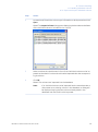
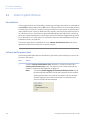
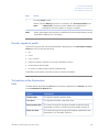
Create a new method
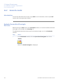
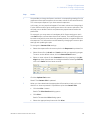
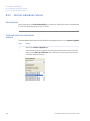
The table below describes how to create a new method:
Step
Action
1
In the Method Editor:
•
click the Create a new method icon in the Toolbar
or
•
select File:New Method...
Result: The New Method dialog opens.
30
UNICORN 6.1 Method Manual 28-9817-65 AB
3 Create and edit methods
3.2 Create and open methods
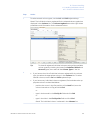
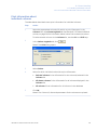
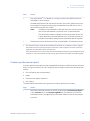
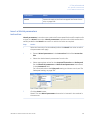
Step
Action
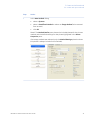
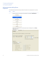
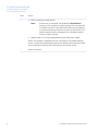
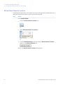
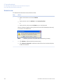
2
In the New Method dialog:
•
select a System
•
select a Predefined Method or select an Empty Method (to be created
from scratch)
•
click OK
Result: The Method Outline pane shows the included phases for the chosen
method and the default settings for the phase highlighted in the Phase
Properties pane.
If an empty method was selected, only the Method Settings phase is shown
(this phase is always included in all methods).
UNICORN 6.1 Method Manual 28-9817-65 AB
31
3 Create and edit methods
3.2 Create and open methods
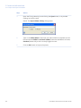
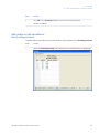
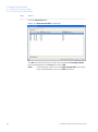
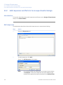
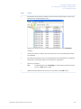
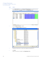
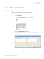
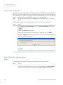
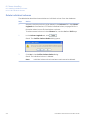
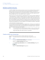
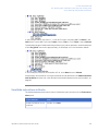
Open a method
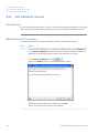
The table below describes how to open an existing method in the database:
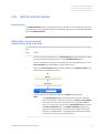
Step
Action
1
In the Method Editor:
•
Click the Open Method Navigator icon in the Toolbar
or
•
select File:Open...
or
•
select View:Method Navigator
Result: The Method Navigator is displayed.
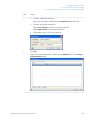
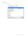
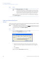
2
32
Select the method to be opened in the Folder name column.
UNICORN 6.1 Method Manual 28-9817-65 AB
3 Create and edit methods
3.2 Create and open methods
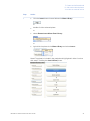
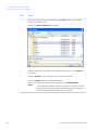
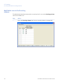
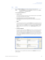
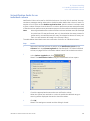
Step
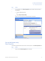
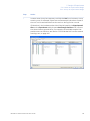
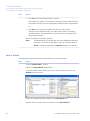
Action
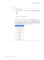
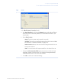
3
To open the method,
•
Click the Open button located in the toolbar of the Method Navigator
pane
or
•
double-click the selected method
or
•
Right-click on the method name and select Open from the context menu
Result: The method is opened and displayed in the Method Outline pane
with included phases. You can continue to edit the phases of the method
using Phase Properties. See Section 3.3 Edit methods and phases, on page 34
for more information about how to edit a method.
UNICORN 6.1 Method Manual 28-9817-65 AB
33
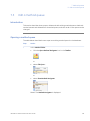
3 Create and edit methods
3.3 Edit methods and phases
3.3
Edit methods and phases
About this section
This section describes how to edit the phase properties for a phase and how to edit the
method outline of a method, that is, determine which phases that should be included in
the method and determine the order of the phases in the method.
In this section
This section contains the following sub-sections:
Section
34
See page
3.3.1 Edit phase properties
35
3.3.2 Edit the method outline
43
UNICORN 6.1 Method Manual 28-9817-65 AB
3 Create and edit methods
3.3 Edit methods and phases
3.3.1 Edit phase properties
3.3.1
Edit phase properties
Introduction
When editing Phase Properties for a phase, the changes affect either
•
the whole method, when editing the Method Settings phase
or
•
only the phase that is being edited, when editing phases other than the Method
Settings phase
UNICORN 6.1 Method Manual 28-9817-65 AB
35
3 Create and edit methods
3.3 Edit methods and phases
3.3.1 Edit phase properties
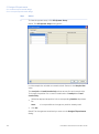
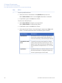
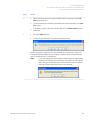
Getting help when editing Phase
Properties
The table below describes how to get help information for the properties in a phase:
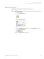
Step
Action
1
Select a phase in the method to be edited, for example, Equilibration.
Result: The properties for the selected phase are displayed in the Phase
Properties pane.
36
UNICORN 6.1 Method Manual 28-9817-65 AB
3 Create and edit methods
3.3 Edit methods and phases
3.3.1 Edit phase properties
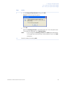
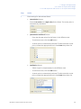
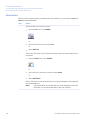
Step
Action
2
Click anywhere in the Phase Properties area to make it the active area in
the software.
3
•
Press the F1 keyboard key.
or
•
Select Help:Contextual Help
Result: The Online help for the selected phase is displayed.
View and edit phases using
Phase Properties
The following table describes how to edit a method phase in the Phase Properties tab:
Step
Action
1
Make sure the Phase Properties tab is selected.
UNICORN 6.1 Method Manual 28-9817-65 AB
37
3 Create and edit methods
3.3 Edit methods and phases
3.3.1 Edit phase properties
Step
Action
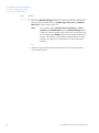
2
•
Select the Method Settings phase if you want to edit basic settings affecting the whole method (e.g., Column type, Flow rate and Method
Base Unit). Continue with steps 3-4.
Note:
You can also edit the Result name & Location, the Start
Protocol and Method Notes from the Method Settings phase.
These are overall method options that also can be set using
the corresponding Toolbar options and not described in this
section. See Section 3.4 Set general method options for the
method, on page 51 for information on how to edit these
settings.
or
•
38
Select any other phase to edit the properties for that specific phase.
Continue with step 5.
UNICORN 6.1 Method Manual 28-9817-65 AB
3 Create and edit methods
3.3 Edit methods and phases
3.3.1 Edit phase properties
Step
Action
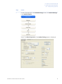
3
To edit the properties for the Method Settings phase, click Method Settings
in the Method Outline.
Result: The Phase Properties of the Method Settings phase is displayed.
UNICORN 6.1 Method Manual 28-9817-65 AB
39
3 Create and edit methods
3.3 Edit methods and phases
3.3.1 Edit phase properties
Step
Action
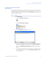
4
Edit the settings for the Method Settings phase in the Phase Properties
pane as appropriate. If changing Column type, UNICORN will automatically
calculate correct settings for volume, flow rate, and pressure limits.
Note:
Settings in this phase will affect the whole method.
Note:
Allowed parameter ranges are shown in parenthesis beside the
text boxes.
Result: The method is updated with the new settings.
40
UNICORN 6.1 Method Manual 28-9817-65 AB
3 Create and edit methods
3.3 Edit methods and phases
3.3.1 Edit phase properties
Step
Action
5
Select a phase in the method to be edited, for example, Equilibration.
Result: The properties for the selected phase are displayed in the Phase
Properties pane.
UNICORN 6.1 Method Manual 28-9817-65 AB
41
3 Create and edit methods
3.3 Edit methods and phases
3.3.1 Edit phase properties
Step
Action
6
•
Edit the settings as appropriate.
Note:
If there are, for example, two predefined Equilibration
phases in your method, changing settings in one of them will
not affect the other. To be able to see that they are different,
it is recommended to rename one of them. See Section 3.3.2
Edit the method outline, on page 43 for information about
how to rename a phase.
•
Repeat steps 5-6 until the appropriate phases have been edited.
Result: The method is updated with the new settings. The edited settings
remain in place while subsequent phases are edited. If the method is closed
and not saved, the settings will revert back to the earlier values.
7
42
Save the method.
UNICORN 6.1 Method Manual 28-9817-65 AB
3 Create and edit methods
3.3 Edit methods and phases
3.3.2 Edit the method outline
3.3.2
Edit the method outline
Introduction
The Method Outline shows the phases that are included in the method and the order
of the phases in the method. Phases can be added, rearranged, renamed and deleted
from the Method Outline.
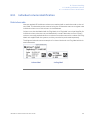
Add a phase to the method
outline using drag-and-drop
The table below describes how to add a phase to the method outline using drag-anddrop:
Step
Action
1
Select the appropriate phase in the Phase Library pane and drag-and-drop
the phase to the requested position in the Method Outline pane.
Result: The phase is included in the method at the requested position. If the
User Defined phase was added, continue with step 2.
2
When the User Defined phase has been added to the Method Outline, the
phase name is enabled for editing.
Type a name for the phase and press the Return keyboard key.
Note:
The User Defined phase is marked with the letter T, meaning
that it is text edited. This phase contains only Base and End_Block
instructions, so any functional instructions must be added by
hand. To include instructions for the User Defined phase, select
the Text Instructions tab. The Phase Properties tab will only
show the variables used in this phase. See Chapter 9 Text edit
methods, on page 286 for information about how to work with
instructions in the text Instructions pane.
UNICORN 6.1 Method Manual 28-9817-65 AB
43
3 Create and edit methods
3.3 Edit methods and phases
3.3.2 Edit the method outline
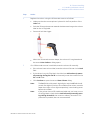
Add a phase to the method
outline using a button or menu
command
The table below describes how to add a phase to the method outline using a button or
menu command:
Step
Action
1
•
Select the appropriate phase (e.g., Equilibration) in the Phase Library
•
Select the appropriate phase (e.g., the Method Settings phase) in the
Method Outline to determine where to place the new phase
Note:
When adding a phase to the Method Outline using a button
or menu command, the new phase is always inserted below
the currently selected phase in the Method Outline.
Result: The selected phase in the Phase Library is indicated by a blue dotted
frame and the selected phase in the Method Outline is highlighted in blue.
44
UNICORN 6.1 Method Manual 28-9817-65 AB
3 Create and edit methods
3.3 Edit methods and phases
3.3.2 Edit the method outline
Step
Action
2
•
Click the Insert button located below the Phase Library
or
•
double-click the selected phase
or
•
select Phases:Insert Phase from Library...
or
•
right-click the phase in the Phase Library and select Insert...
Result: The phase is included in the method and highlighted in blue. Continue
with step 3 if adding the User Defined phase.
UNICORN 6.1 Method Manual 28-9817-65 AB
45
3 Create and edit methods
3.3 Edit methods and phases
3.3.2 Edit the method outline
Step
Action
3
When the User Defined phase has been added to the Method Outline, the
phase name is enabled for editing.
Type a name for the phase and press the Return keyboard key.
Note:
The User Defined phase is marked with the letter T, meaning
that it is text edited. This phase contains only Base and End_Block
instructions, so any functional instructions must be added by
hand. To include instructions for the User Defined phase, select
the Text Instructions tab. The Phase Properties tab will only
show the variables used in this phase. See Chapter 9 Text edit
methods, on page 286 for information about how to work with
instructions in the text Instructions pane.
Rename phases
Note:
It is only possible to rename phases in the Method Outline pane, not in the
Phase Library.
The table below describes how to rename a phase in the method:
46
Step
Action
1
Select the phase to be renamed in the Method Outline pane.
UNICORN 6.1 Method Manual 28-9817-65 AB
3 Create and edit methods
3.3 Edit methods and phases
3.3.2 Edit the method outline
Step
Action
2
•
right-click the phase and select Rename
or
•
press the F2 keyboard key
or
•
select Edit:Rename
Result: The name in the phase becomes editable.
3
Type an appropriate name and click Return keyboard key.
Result: The name of the phase is updated.
UNICORN 6.1 Method Manual 28-9817-65 AB
47
3 Create and edit methods
3.3 Edit methods and phases
3.3.2 Edit the method outline
Rearrange phases within a
method
The table below describes how to rearrange phases within a method:
Step
Action
1
Select the phase to be moved in the Method Outline pane.
2
•
Drag-and-drop the phase to the requested position in the Method Outline
pane.
Result: The phase is moved to the requested position.
or
•
Right-click the phase and select Move up or Move down.
Result: The phase is moved one step up or down in the Method Outline.
Delete a phase from the Method
Outline
The table below describes how to delete a phase from the Method Outline:
48
Step
Action
1
Select the phase to delete from the method in the Method Outline.
UNICORN 6.1 Method Manual 28-9817-65 AB
3 Create and edit methods
3.3 Edit methods and phases
3.3.2 Edit the method outline
Step
Action
2
•
Click the Delete button below the Method Outline pane.
or
•
Press the Delete key on the keyboard.
or
•
select Edit:Delete
or
•
Right-click on the phase and select Delete from the context menu.
Result: The phase is removed from the method.
UNICORN 6.1 Method Manual 28-9817-65 AB
49
3 Create and edit methods
3.3 Edit methods and phases
3.3.2 Edit the method outline
Copy, cut and paste phases in a
method
Note:
It is only possible to copy, cut and paste phases in the Method Outline pane,
not in the Phase Library.
The features copy, cut and paste phases can be used to add/delete and rearrange
phases in the Method Outline. The table below describes the copy, cut and paste a phase
features.
To...
then...
copy a phase
select the phase and:
•
right-click the phase and select Copy
or
•
use the shortcut Ctrl +C
or
•
cut a phase
select Edit:Copy
select the phase and:
•
right-click the phase and select Cut
or
•
use the shortcut Ctrl +X
or
•
paste a phase
select Edit:Cut
Note:
The phase to be pasted will be pasted below
the phase highlighted in the Method Outline.
Select the appropriate phase in the Method Outline. Then:
•
right-click the highlighted phase in the Method Outline
and select Paste
or
•
use the shortcut Ctrl +V
or
•
50
select Edit:Paste
UNICORN 6.1 Method Manual 28-9817-65 AB
3 Create and edit methods
3.4 Set general method options for the method
3.4
Set general method options for the method
Introduction
This section describes how to set and view options for an entire method. The following
are covered in this section:
•
Defining the name and location for the results.
•
How to set up a Start Protocol that will be displayed before each method run.
•
Adding or changing method notes.
•
How to include evaulation procedures which can be executed during the run.
•
Viewing the method duration time and volume.
•
Viewing the variables used in the method.
UNICORN 6.1 Method Manual 28-9817-65 AB
51
3 Create and edit methods
3.4 Set general method options for the method
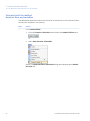
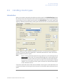
Define Result Name & Location
The table below describes how to define the name of the result file created after the run
and how to specify the folder in which to save the result file.
Step
Action
1
In the Method Editor:
•
click the Result Name & Location icon
or
•
select Edit:Result Name & Location...
or
•
click the Method Settings phase and click the Result Name & Location...
button in the Phase Properties tab
Result: The Result Name & Location dialog opens.
52
UNICORN 6.1 Method Manual 28-9817-65 AB
3 Create and edit methods
3.4 Set general method options for the method
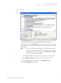
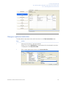
Step
Action
2
In the Result Name & Location dialog:
•
Set Result location by clicking the Browse button and select a folder in
which to save the results. By default, the results will be saved in your
home folder.
•
Select Result name.
-
Name: The result name can be typed in manually
-
Variable: The result name will be generated from the chosen variable
(see Section 9.2.4 Method variables, on page 315)
-
Method name (default): The result name will be generated from the
name of the method
-
Date: The result name will be generated from the date of the run
•
Check the Add unique identifier box if you want to include a unique
identifier number to the file name. The number will be generated by
UNICORN based on the run time of the method.
•
Click OK to confirm and close the dialog.
UNICORN 6.1 Method Manual 28-9817-65 AB
53
3 Create and edit methods
3.4 Set general method options for the method
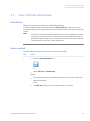
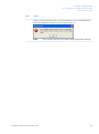
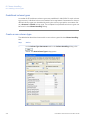
Set up a Start Protocol
The table below describes how to set up a Start Protocol to be displayed before the run
starts.
Step
Action
1
In the Method Editor:
•
click the Start Protocol icon
or
•
select Tools:Start Protocol...
or
•
click the Method Settings phase and click the Start Protocol... button
in the Phase Properties tab
Result: The Start Protocol dialog opens.
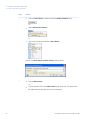
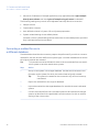
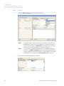
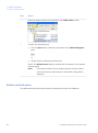
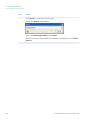
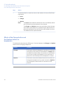
2
In the Start Protocol dialog:
54
•
Select items to display at method start. When selecting a method item,
a description is shown to the right. Result Name and Location is selected
by default.
•
Click OK to confirm and close the dialog.
UNICORN 6.1 Method Manual 28-9817-65 AB
3 Create and edit methods
3.4 Set general method options for the method
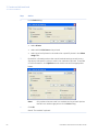
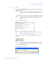
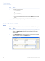
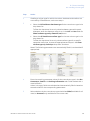
Add/edit Method Notes
The table below describes how to add/edit notes to a method.
Step
Action
1
In the Method Editor:
•
click the Method Notes icon
or
•
select Edit:Method Notes...
or
•
click the Method Settings phase and click the Method Notes... button
in the Phase Properties tab
Result: The Method Notes dialog opens.
UNICORN 6.1 Method Manual 28-9817-65 AB
55
3 Create and edit methods
3.4 Set general method options for the method
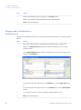
Step
Action
2
In the Method Notes dialog:
•
Enter/edit notes about the method. If notes already have been entered,
it is possible to search for specific words using the Find... button.
• Click OK to confirm and close the dialog.
Note:
Information will automatically be added to the Method Notes if
the method has been converted for use with another ÄKTA avant
system type than what it was originally created for, or scaled for
another column type than what was originally selected.
56
UNICORN 6.1 Method Manual 28-9817-65 AB
3 Create and edit methods
3.4 Set general method options for the method
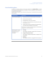
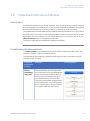
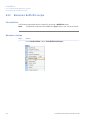
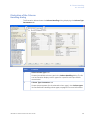
Include Evaluation Procedures
after the run
The table below describes how to include an evaluation procedure in the method. The
evaluation procedure will be performed automatically after the run has finished. The
evaluation procedures must have been defined in the Evaluation module, see the UNICORN 6.1 Evaluation Manual.
Step
Action
1
In the Method Editor:
•
click the Evaluation Procedures icon
or
•
select Tools:Evaluation Procedures...
Result: The Evaluation Procedures dialog opens.
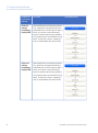
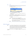
2
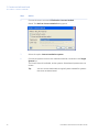
•
If there are no evaluation procedures listed in the Evaluation Procedures
dialog, click the Import... button to import an evaluation procedure.
Result: The Import Evaluation Procedure dialog opens. Continue with
step 3.
•
If an evaluation procedure that should be used in the run has been saved
in the method earlier, it is shown in the Evaluation Procedures dialog.
Continue with step 4.
UNICORN 6.1 Method Manual 28-9817-65 AB
57
3 Create and edit methods
3.4 Set general method options for the method
Step
Action
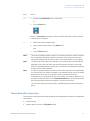
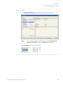
3
In the Import Evaluation Procedures dialog:
•
Select the appropriate procedure to import in the Select procedure to
import field.
•
It is possible to change the name of the procedure to be displayed in
your method by changing the name in the Import as field.
• Click Import to import the procedure
Note:
Only Global procedures and your own Personal procedures are
shown in the list.
Note:
It is also possible to import a procedure saved in another method
by browsing to the appropriate folder and selecting the method
containing the procedure. The procedure will be listed in the Select procedure to import field and can be imported as described
above.
Result: The evaluation procedure is listed in the Evaluation Procedures dialog.
58
UNICORN 6.1 Method Manual 28-9817-65 AB
3 Create and edit methods
3.4 Set general method options for the method
Step
Action
4
Make sure the box in front of the evaluation procedure is checked to include
it in the method.
Click Close.
Result: The evaluation procedure is included in the method.
Note:
It is possible to edit an existing evaluation procedure by selecting
it and clicking Edit.... The edits will only change the procedure
that is included in the method. See the UNICORN 6.1 Evaluation
Manual for information about how to edit an evaluation procedure.
UNICORN 6.1 Method Manual 28-9817-65 AB
59
3 Create and edit methods
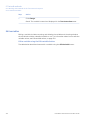
3.4 Set general method options for the method
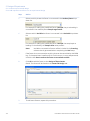
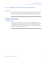
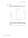
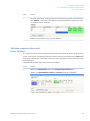
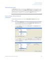
View and print the method
duration time and variables
The table below describes how to view and print an estimation of the method duration
time and the variables in the method:
Step
Action
1
In the Method Editor:
•
click the Duration & Variables button below the Method Outline pane
or
•
select View:Duration & Variables
Result: The Method Duration & Variables dialog opens displaying the Method
Duration tab.
60
UNICORN 6.1 Method Manual 28-9817-65 AB
3 Create and edit methods
3.4 Set general method options for the method
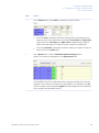
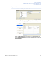
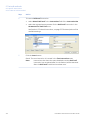
Step
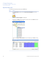
Action
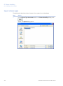
2
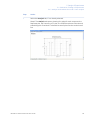
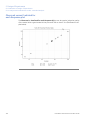
The Method Duration tab shows an estimation of the accumulated method
time and volume for the current method below the text method.
If the method includes a Scouting series, an estimation of the accumulated
method time and volume for the total series of runs is displayed below the
text method.
Note:
Click the arrow buttons to display the different scouting runs.
The accumulated time/volume is an approximation and does
not take into account time or volume for Watch blocks, Wash
commands or programmed Hold.
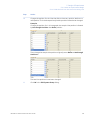
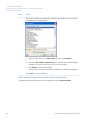
3
4
•
Select Time as Base to show the time in minutes in the text method.
•
Select Volume as Base to show the volume in the text method.
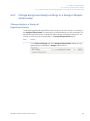
To view the variables in the method, click the Variable List tab.
Result: The Variable List is displayed.
UNICORN 6.1 Method Manual 28-9817-65 AB
61
3 Create and edit methods
3.4 Set general method options for the method
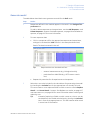
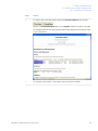
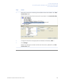
Step
Action
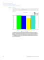
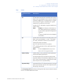
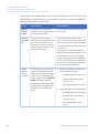
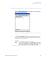
5
The Variable List shows the variables in the method. It is also possible to
see in which phases the variables are included and the different values.
Variables with an ellipsis (...) after their name are used in multiple phases or
blocks. It is not possible to change any values in this dialog.
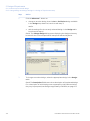
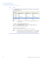
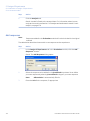
6
•
Check the Show details box to view variables classified as detailed. The
letter D will be shown to the left of the detailed variables.
•
Check the Show unused variables box to view unused variables in the
method. The letter U will be shown to the left of unused variables.
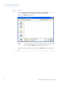
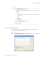
To print the information in the Method Duration & Variables dialog, click
the Print... button.
Result: The Print dialog opens.
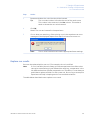
7
Select a Printer from the drop-down list and click OK.
Result: The information is printed.
62
UNICORN 6.1 Method Manual 28-9817-65 AB
3 Create and edit methods
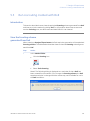
3.5 Save methods and phases
3.5
Save methods and phases
Introduction
Methods and phases are saved in the UNICORN database.
Individual, edited phases may be saved to the Phase Library for later use in other
methods on systems having the same instrument configuration and component configuration.
Note:
You cannot save an edited method/phase to replace a predefined method
or phase. If you want to save an edited variant of a predefined method or
phase with specific settings, you must save it under another name. A predefined method or phase can not be overwritten.
Save a method
The table below describes how to save a method in UNICORN.
Step
Action
1
•
Click the Save the Method icon
or
•
select File:Save or File:Save As.
Result:
•
If the method has been named and saved previously, the changes are
saved immediately.
If not
•
The Save As dialog opens. Proceed with steps 2-4 below.
UNICORN 6.1 Method Manual 28-9817-65 AB
63
3 Create and edit methods
3.5 Save methods and phases
64
Step
Action
2
Browse for an appropriate folder, or create a new one.
3
•
Select the folder in which to save the results.
•
Enter a method Name.
•
Select for which System to save the method
UNICORN 6.1 Method Manual 28-9817-65 AB
3 Create and edit methods
3.5 Save methods and phases
Step
Action
4
Click Save.
Result: The method is saved in the database.
Note:
An error message will appear if you are trying to save the method
for:
•
a system using another instrument configuration and/or
another component configuration than the method originally
was created for
and
•
the settings in the method depends on the component configuration (e.g., if an extra inlet A valve is used in the method,
this setting cannot be used in a system lacking the extra inlet
A valve.)
It will still be possible to save the method but the phases in the
method will be marked with an error symbol. In order to be able
to subsequently run the method, either the method must be textedited or the component configuration of the system changed
in the Administration module.
Save a phase
The table below describes how to save a phase to the Phase Library:
Step
Action
1
Select the phase to be saved in the method outline.
Note:
A Method Settings phase can not be saved as a separate phase
with a new name. If editing properties for the Method Settings
phase, the changes will be saved with the method.
UNICORN 6.1 Method Manual 28-9817-65 AB
65
3 Create and edit methods
3.5 Save methods and phases
Step
Action
2
•
click the Save Phase... button below the Method Outline pane
or
•
select Phases:Save Phase...
or
•
right-click the phase and select Save Phase...
Result: The Save Phase to Phase Library dialog opens.
3
•
Type a Phase name
or
•
66
Choose a phase from the Phase name drop-down list. This phase will
be replaced by the phase with the new settings.
UNICORN 6.1 Method Manual 28-9817-65 AB
3 Create and edit methods
3.5 Save methods and phases
Step
Action
4
In the For system field, the system that was selected when the current
method was set up will be displayed by default. To save the phase for another
system, choose the appropriate system from the For system drop-down
list.
Note:
Only systems using the same instrument configuration and
component configuration as the system that was selected when
the current method was set up will be displayed in the For system
field.
5
•
Select if the phase shall be Global (available for all users) or Personal
(for your own use only).
• Click OK.
Note:
It is not possible to replace a predefined phase by saving an existing phase.
Result: The phase is saved and is available in the Global Phases or Personal
Phases panel of the Phase Library.
Delete a phase from the Phase
Library
It is possible to delete personal and global phases from the Phase Library. Predefined
phases cannot be deleted.
The table below describes how to delete a personal or global phase from the phase library:
UNICORN 6.1 Method Manual 28-9817-65 AB
67
3 Create and edit methods
3.5 Save methods and phases
Step
Action
1
Select the appropriate phase library: Personal Phases or Global Phases at
the bottom of the Phase Library pane.
Result: The phases in that phase library are displayed.
2
Select the phase to delete from the library.
3
•
Click the Delete button at the bottom of the Phase Library pane.
or
•
Right-click the phase and select Delete.
Result: The phase is removed from the Phase Library.
68
UNICORN 6.1 Method Manual 28-9817-65 AB
3 Create and edit methods
3.6 Scale or convert methods
3.6
Scale or convert methods
Introduction
UNICORN methods are always created specifically for a designated system and thus
also for a specific system type (e.g. ÄKTA avant 25). However, it is often useful to convert
a method that was originally created for a system of one type , for use with another a
system of another type (e.g. ÄKTA avant 150). The converted method is created as a
copy of the original method. The original method remains saved.
When a method is converted, it can also be scaled for use with a different column type
than what it was originally created for. Both processes are described in this section.
Tip:
If you wish to use a method for another system of the same ÄKTA avant
system type that it was originally created for, you only need to choose
File:Save As, select the new system and save the method with another name.
To only change the selected column type, you should edit the method, change
the column selection and save the edited method.
Prerequisites
The following items should be considered to ensure that the method conversion and
scaling is successful:
•
The original method should use column volume (CV) as base
•
All parameters that will require scaling should be defined as variables
•
If linear flow is to be maintained in the scaled method, it must have been applied in
the original method as well
•
Scaling of the column type is not possible if the Any column type was selected in the
original method
•
Text edited phases will not be automatically updated during the conversion
Convert a method to another
system type
The table below describes how to convert a method to be used with another system
type.
Step
Action
1
Open the method you want to convert in the Method Editor.
UNICORN 6.1 Method Manual 28-9817-65 AB
69
3 Create and edit methods
3.6 Scale or convert methods
Step
Action
2
Choose the menu command File:Scale or Convert Method
Result: The Scale or Convert Method dialog opens.
3
Select the option Convert method to system.
4
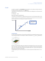
Choose the system to which the method should be converted in the Target
System list.
The list will show all available, active systems. Deactivated systems are not
shown.
Tip:
You can convert methods that originally were created for systems
that now are deactivated.
70
UNICORN 6.1 Method Manual 28-9817-65 AB
3 Create and edit methods
3.6 Scale or convert methods
Step
Action
5
Click the OK button.
Result: The method is converted as an untitled copy (UNTITLED converted*).
The Method Notes dialog opens, showing basic information about the conversion.
Note:
6
•
The information shown in the Method Notes will not include details about scaled system related parameters (e.g. wash or delay
volumes) or notes concerning method instructions that may have
become invalid as a result of conversion between systems with
different components and instrument configurations. You must
verify that there are no phases with invalid instructions (i.e.
phases marked with a red cross) in the new method before it can
be used. See note below this instruction.
Type any additional notes you wish to add in the text field
and
•
click the OK button to close the Method Notes dialog.
UNICORN 6.1 Method Manual 28-9817-65 AB
71
3 Create and edit methods
3.6 Scale or convert methods
Step
Action
7
•
Choose the File:Save As menu command to save the converted method
or
•
click the Save icon
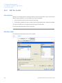
Result: The Save As dialog opens, with the folder where the original method
is saved open by default.
8
•
Select the desired target folder,
•
type a new method name in the Name field
and
•
Note:
Note:
Note:
72
click the Save button.
The original method remains after the converted method is saved. However,
the converted method will replace the original if you choose to save the
converted method with the same name in the same folder as the original.
The flow rate and/or pressure settings in the method will automatically be
adjusted if the maximum flow rate and/or pressure values for the target
system is exceeded after the conversion. The maximum settings for the target
system will be used by default.
In case the original method contains instructions that are not supported by
the new system, this will be indicated in the method outline of the converted
method as a red cross on the phase containing these instructions.
To be able to run the method on the new system you need to replace or remove the invalid instructions in the Text Instructions pane. Invalid instructions
are indicated with red square symbols in the text instructions.
You can also replace the phase with a predefined phase from the phase library.
UNICORN 6.1 Method Manual 28-9817-65 AB
3 Create and edit methods
3.6 Scale or convert methods
Convert and scale a method up
or down
The table below describes how to convert a method to be used with another system
type, and at the same time scale the method to be used with another column size.
Step
Action
1
Open the method you want to convert and scale in the Method Editor.
2
Choose the menu command File:Scale or Convert Method
Result: The Scale or Convert Method dialog opens.
3
Select the option Convert and Scale up/down method.
4
Choose the system to which the method should be converted in the Target
System list.
UNICORN 6.1 Method Manual 28-9817-65 AB
73
3 Create and edit methods
3.6 Scale or convert methods
Step
Action
5
By default, the same column type that was selected in the original method
is shown in the Column Type field.
•
Click the Select Column... button to select a new column type.
Result: The Select Column Type dialog opens.
74
UNICORN 6.1 Method Manual 28-9817-65 AB
3 Create and edit methods
3.6 Scale or convert methods
Step
Action
6
•
Select the column type from the list of available column types
and
•
click the OK button.
Result: The Select Column Type dialog closes and the selected column is
shown in the Column Type field of the Scale or Convert Method dialog.
7
If desired, select the Keep linear flow on new column option.
Note:
This option is applicable only if linear flow was selected in the
original method. If linear flow is not selected, the default flow
settings for the selected column type will be used.
UNICORN 6.1 Method Manual 28-9817-65 AB
75
3 Create and edit methods
3.6 Scale or convert methods
Step
Action
8
Click the OK button.
Result: The method is scaled as an untitled copy (UNTITLED converted*).
The Method Notes dialog opens, showing basic information about the conversion.
Note:
9
•
The information shown in the Method Notes will not include details about scaled system related parameters (e.g. wash or delay
volumes) or notes concerning method instructions that may have
become invalid as a result of conversion between systems with
different components and instrument configurations. You must
verify that there are no phases with invalid instructions (i.e.
phases marked with a red cross) in the new method before it can
be used. See note below this instruction.
Type any additional notes you wish to add in the text field
and
•
76
click the OK button to close the Method Notes dialog.
UNICORN 6.1 Method Manual 28-9817-65 AB
3 Create and edit methods
3.6 Scale or convert methods
Step
Action
10
•
Choose the File:Save As menu command
or
•
click the Save icon
Result: The Save As dialog opens, with the folder where the original method
is saved open by default.
11
•
Select the desired target folder,
•
type a new method name in the Name field
and
•
Note:
Note:
Note:
click the Save button.
The original method remains after the converted method is saved. However,
the converted method will replace the original if you choose to save the
converted method with the same name in the same folder as the original.
The flow rate and/or pressure settings in the method will automatically be
adjusted if the maximum flow rate and/or pressure values for the target
system is exceeded after the conversion. The maximum settings for the target
system will be used by default.
In case the original method contains instructions that are not supported by
the new system, this will be indicated in the method outline of the converted
method as a red cross on the phase containing these instructions.
To be able to run the method on the new system you need to replace or remove the invalid instructions in the Text Instructions pane. Invalid instructions
are indicated with red square symbols in the text instructions.
You can also replace the phase with a predefined phase from the phase library.
The method after conversion
The conversion will adjust the following settings to the appropriate values for the selected
new system:
•
Gradient delay
•
System wash volume (i.e. Fill system value)
UNICORN 6.1 Method Manual 28-9817-65 AB
77
3 Create and edit methods
3.6 Scale or convert methods
•
Volume for finalization of sample application (only applicable when Inject sample
directly onto column and then Inject all sample using air sensor is selected)
The following settings may remain to be adjusted manually after the conversion:
•
Sample volume
•
Fractionation volumes
•
User defined volumes in System CIP and System preparation
•
System related settings in text edited phases
(However, column related settings will be scaled also in text edited phases, provided
they have been defined as variables)
Converting a method for use in
a different database
The table below describes the necessary steps to be performed if you wish to convert a
method for use with another ÄKTA avant system type, in another database than where
the original method was created.
Tip:
This procedure must be followed in order to convert methods from one standalone system to another stand-alone system.
78
Step
Action
1
Set up a new system in the target database. Use the same instrument configuration as the system for which the method was originally created.
Tip:
This system is created for the conversion only and can be set up
inactivated.
2
Export the method from the original database.
3
Import the method into the target database, for use with the new, inactivated
system.
4
Convert the method from the inactivated system to be used with the target
system, as described in the applicable instruction above (i.e. with or without
scaling of the column size).
UNICORN 6.1 Method Manual 28-9817-65 AB
3 Create and edit methods
3.7 Print a method
3.7
Print a method
Introduction
This section describes how to print a method’s text instructions and variables. UNICORN
uses the printers and printer settings that are installed on your computer.
Print a method
The table below describes how to print an opened method:
Step
Action
1
•
Click the Print icon in the Toolbar
or
•
select File:Print...
Result: The Print dialog opens.
UNICORN 6.1 Method Manual 28-9817-65 AB
79
3 Create and edit methods
3.7 Print a method
Step
Action
2
In the Print dialog:
3
•
select Printer
•
select which Print items to be printed
•
select to print all phases in the method or a specific phase in the Phase
range field
By default, information about the overall method settings as well as any
signatures and specific columns used in the method are printed. To exclude
or add information, click Options>> and check/uncheck the appropriate
boxes.
Note:
4
Only options that are used in a method can be printed. Options
that are not used are greyed out in the Print dialog.
Click OK.
Result: The method is printed.
80
UNICORN 6.1 Method Manual 28-9817-65 AB
3 Create and edit methods
3.8 Predefined methods and phases
3.8
Predefined methods and phases
Introduction
A predefined method contains a set of phases, each phase reflecting a specific stage of
a chromatography or maintenance run. You can select additional phases from the phase
libraries and add these to an existing method, or remove an undesired phase.
The predefined purification methods have default values with suitable running conditions
for the chosen column type such as flow and pressure limits. Other settings (e.g., sample
application technique, sample volume, elution profile and fractionation) are set on the
Phase Properties pane in the appropriate phases.
This section describes the predefined methods and phases.
Predefined purification methods
The Method Editor has predefined methods for different separation techniques. The
methods include a number of relevant phases.
The table below describes the available predefined purification methods and which
phases that are included.
Predefined
purification
method
Principle
Affinity
Chromatography (AC)
After equilibration and sample application, the protein of interest is adsorbed
to the column ligand. After a wash to
remove unbound sample, elution is
performed either by using a buffer
containing a competitor to displace the
protein of interest, or by changing the
pH or ionic strength. Finally, the column
is re-equilibrated with start buffer.
UNICORN 6.1 Method Manual 28-9817-65 AB
Included phases
81
3 Create and edit methods
3.8 Predefined methods and phases
82
Predefined
purification
method
Principle
Included phases
Anion Exchange
Chromatography (AIEX)
After equilibration and sample application, negatively charged proteins are
adsorbed to the column ligand. After a
wash, to remove unbound sample,
elution is performed using a gradient
of increasing salt concentration (of e.g.
NaCl). Finally, the column is washed
and re-equilibrated with start buffer.
Cation Exchange
Chromatography (CIEX)
After equilibration and sample application, positively charged proteins are
adsorbed to the column ligand. After a
wash, to remove unbound sample,
elution is performed using a gradient
of increasing salt concentration (of e.g.
NaCl). Finally, the column is washed
and re-equilibrated with start buffer.
UNICORN 6.1 Method Manual 28-9817-65 AB
3 Create and edit methods
3.8 Predefined methods and phases
Predefined
purification
method
Principle
Chromatofocusing (CF)
After equilibration and sample application, elution is performed using a pH
gradient. The proteins separate and
elute according to their isoelectric
points. Finally, the column is re-equilibrated.
Desalting
After equilibration and sample application, the proteins are eluted isocratically. This technique is commonly used for
buffer exchange.
Gel filtration (GF)
After equilibration and sample application, proteins separate and elute according to their size (largest first).
UNICORN 6.1 Method Manual 28-9817-65 AB
Included phases
83
3 Create and edit methods
3.8 Predefined methods and phases
Predefined
purification
method
Principle
Included phases
Hydrophobic Interaction Chromatography (HIC)
After equilibration and sample application (use a buffer containing a high salt
concentration, for example 2 M Ammonium Sulphate) hydrophobic proteins
are adsobed to the column ligand. After
a wash to remove unbound sample,
elution is performed using a gradient
of decreasing salt concentration. Finally, the column is washed and re-equilibrated with start buffer.
Reversed
Phase Chromatography (RPC)
After equilibration and sample application, hydrophobic proteins adsorb to
the column ligand. After a wash to remove unbound sample, elution is performed by generating a gradient of a
non-polar, organic solvent such as
Acetonitrile. Finally, the column is
washed and re-equilibrated.
WARNING
Fraction collector. Do not fractionate flammable liquids. When
running RPC methods, or other procedures using organic solvents,
collect fractions through the Outlet valve.
84
UNICORN 6.1 Method Manual 28-9817-65 AB
3 Create and edit methods
3.8 Predefined methods and phases
Predefined maintenance
methods
A number of predefined methods for preparation and cleaning are available. These
maintenance methods are used to prepare the system, clean the system, and to fill the
system with storage solution.
The table below describes the available predefined maintenance methods.
Predefined
maintenance
method
Principle
Column
CIP
The column is filled with a cleaning solution.
Select inlet positions. Enter the solution
identity, volume, flow rate and incubation
time. By adding steps, several cleaning solutions can be used. Suggestions for cleaning steps are available for a number of column types.
Column
Performance
Test
After equilibration of the column, sample is
injected via a capillary loop and eluted isocratically. A non-adsorbing sample like
acetone or salt should be used. After the
run, calculate column performance in the
Evaluation module. The efficiency of the
column is determined in terms of height
equivalent to a theoretical plate (HETP), and
the peak asymmetry factor (As). The result
is logged in the column logbook.
Column
Preparation
The column is filled with buffer solution.
Select inlet positions. Enter the solution
identity, volume, flow rate and incubation
time. By adding steps, several preparation
solutions can be used.
UNICORN 6.1 Method Manual 28-9817-65 AB
Included phases
85
3 Create and edit methods
3.8 Predefined methods and phases
Predefined
maintenance
method
Principle
Included phases
Intelligent
Packing
Packs AxiChrom columns, with a predetermined column type, by a flow of hydraulic
liquid that pushes the adaptor down. The
user initiates the start of compression at
the exact point when the adapter reaches
the consolidated bed surface. The adapter
compresses the bed according to the
packing factor or target bed height as selected. Two Column Performance Test (upflow/downflow) phases are automatically
performed after the AxiChrom column has
been packed.
Only available for ÄKTA avant 150.
86
System
CIP
The system is filled with cleaning solution.
Select for example inlets, outlets and column positions to be cleaned. Three System
CIP phases are included in the method to
facilitate the use of three different cleaning
solution. Additional System CIP phases can
be added from the Phase Library if desired.
System
Preparation
The system is filled with preparation solution. Select for example inlets, outlets and
column positions to be prepared. Two System Preparation phases are included in the
method. Additional System Preparation
phases can be added from the Phase Library if desired.
UNICORN 6.1 Method Manual 28-9817-65 AB
3 Create and edit methods
3.8 Predefined methods and phases
Predefined phases
The table below describes the predefined phases.
Phase Name
Description
Method Settings
The first, and mandatory, phase in any method. Defines common
parameters used in the subsequent phases.
The Method Settings phase defines:
•
Column type
•
Pressure limits
•
Flow rate
• Option to control the flow to avoid overpressure
Note:
Default values for pressure limits and flow rate are
given for the selected column type
•
Column position
•
Flow restrictor use
•
Buffer preparation:
-
Manual, or
-
BufferPro (automatic buffer preparation)
•
Unit selection for Method base and Flow rate
•
Monitor settings:
-
UV monitor
-
pH monitor
-
Air sensor alarm settings
•
Settings for Column Logbook
•
Start Protocol
• Result name and location
Note:
Some of these options may not be required by certain
methods.
Equilibration
Equilibrates the column before purification, or re-equilibrates the
column after purification.
Sample Application
Applies sample to the column. Defines the sample application
technique, the sample volume, and the handling of flowthrough.
UNICORN 6.1 Method Manual 28-9817-65 AB
87
3 Create and edit methods
3.8 Predefined methods and phases
Phase Name
Description
Column Wash
Washes out unbound sample after sample application or removes
strongly bound proteins after elution.
Elution
Elutes the sample from the column. Defines parameters for the
elution and fractionation settings.
Column Preparation
Prepares the column before use by removing the storage solution
and equilibrating the column. By adding steps, several preparation solutions can be used sequentially.
Column CIP
Cleans the column after purification runs by rinsing the column
with a cleaning solution to remove unspecifically bound proteins.
By adding steps, several cleaning solutions can be used sequentially.
System Preparation
Prepares the system before a run by removing storage solution
and filling the system and inlets with buffer solution. One preparation solution is used per phase.
System CIP
Cleans the system after purification runs by rinsing the system
with a cleaning solution. One cleaning solution is used per phase.
Column performance test
Tests the efficiency of a packed column in terms of height
equivalent to a theoretical plate (HETP), and the peak asymmetry
factor (As).
Intelligent Packing
A flow of hydraulic liquid pushes the adapter down. The user initiates the start of compression at the exact point when the
adapter reaches the consolidated bed surface. The adapter
compresses the bed according to the packing factor or target
bed height as selected.
Only available for ÄKTA avant 150.
88
UNICORN 6.1 Method Manual 28-9817-65 AB
3 Create and edit methods
3.9 Fraction collection
3.9
Fraction collection
Introduction
For many purification schemes it is convenient to collect fractions of the eluent. Several
of the predefined phases and methods include options for fraction collection in the Phase
Properties pane.
This section describes briefly the various options available for fractionation in predefined
methods and phases, and how to set up fraction collection when editing a method. More
detailed information for individual settings can be found using the online help for the
phase, see Getting help when editing Phase Properties, on page 36.
Fractionation overview
Fractionation is available in the Phase Properties pane in the predefined phases Sample
Application , Column Wash and Elution. These three phases are included in many of
the predefined methods in UNICORN. This option will also be available in personal or
global phases derived from these. See Section 3.3.1 Edit phase properties, on page 35
for details on how to edit methods and phases.
For each phase, fractions can either be collected using the outlet valve or the fraction
collector. If there is no risk of sample loss, the eluate may be sent to the waste and not
collected. When fractionating to the outlet valve, a specific outlet valve position is selected.
When collecting fractions in the fraction collector a tube or plate type is chosen and the
fractions will be collected in the first available tube or plate of that type.
WARNING
Fraction collector. Do not fractionate flammable liquids. When
running RPC methods, or other procedures using organic solvents,
collect fractions through the Outlet valve.
UNICORN 6.1 Method Manual 28-9817-65 AB
89
3 Create and edit methods
3.9 Fraction collection
Fractionation setup
The following table describes the steps needed to set up fraction collection in the Phase
Properties pane:
Step
Action
1
Select the phase for which fractionation is required in the method outline
and select the Phase Properties pane.
Note:
90
Text edited phases will show the fractionation options as variables in the Phase Variables list, see Chapter 9 Text edit methods,
on page 286.
UNICORN 6.1 Method Manual 28-9817-65 AB
3 Create and edit methods
3.9 Fraction collection
Step
Action
2
Using the Fractionate radio buttons, select the fractionation type required
for this phase:
3
•
using outlet valve enables fraction collection using the outlet valve. The
Fractionation settings will change to reflect this choice, and the outlet
valve position can be selected as the Fractionation destination.
•
using fraction collector enables fraction collection in the fraction collector. The Fractionation settings will change to reflect this choice, and the
desired Fractionation destination can be chosen from the drop-down
list.
•
in waste (do not collect) will send the eluent to the waste.
Edit the Fractionation settings as appropriate. For detailed information on
these settings see the online help for the phase, refer to Getting help when
editing Phase Properties, on page 36.
UNICORN 6.1 Method Manual 28-9817-65 AB
91
3 Create and edit methods
3.10 Sign methods electronically
3.10 Sign methods electronically
Introduction
Methods can be signed electronically to enhance data file security. Once a method has
been signed, it is not possible to edit the method.
Tip:
To edit a signed method create a new method using the settings in the signed
method by selecting File:Save As... and save the method with a new name.
Sign a method electronically in
the Method Editor
The table below describes how to sign a method electronically in the Method Editor:
Step
Action
1
Select File:Sign Method....
Result: The Sign Method dialog opens.
92
UNICORN 6.1 Method Manual 28-9817-65 AB
3 Create and edit methods
3.10 Sign methods electronically
Step
Action
2
•
The Signing user field shows the user currently logged on.
If you are to sign the method but are not the one logged on to UNICORN,
select your user name in the Signing user drop-down list. Your Full name
and Job title are displayed.
•
Type your Log on password to UNICORN.
•
Type a Signature description if appropriate.
•
Type your Signature password and click OK.
Result: The method has been signed.
UNICORN 6.1 Method Manual 28-9817-65 AB
93
3 Create and edit methods
3.11 Import and export methods
3.11 Import and export methods
Introduction
UNICORN methods are stored internally in the UNICORN database. It is however possible
to export entire methods or individual phases to a zip file on the local computer so that
they can be imported again later into the same database installation, or imported into
another database installation.
Alternatively methods or phases can be exported as plain text files or Excel files, which
may be useful for documentation purposes.
94
UNICORN 6.1 Method Manual 28-9817-65 AB
3 Create and edit methods
3.11 Import and export methods
Export a phase or method to
UNICORN
The following table outlines the steps needed to export a method or a phase for later
import into UNICORN.
Step
Action
1
In the Method Navigator, select the method to be exported.
or
In the Phase Library pane, select the phase to be exported.
Note:
Note:
UNICORN 6.1 Method Manual 28-9817-65 AB
Only Personal or Global phases may be exported.
Only single methods or phases may be exported, it is not possible
to write multiple methods or phases to a single zip file.
95
3 Create and edit methods
3.11 Import and export methods
Step
Action
2
Choose File:Export:to UNICORN:Export Method to UNICORN....
Result: The Export dialog opens.
Note:
3
96
In the case of phases, it is also possible to right-click on the phase
name and select Export... from the context menu.
Choose a file name and location and click the Save button to save the zip
file.
UNICORN 6.1 Method Manual 28-9817-65 AB
3 Create and edit methods
3.11 Import and export methods
Export a method to a plain text
file
The following table outlines the steps needed to export a method as a plain text file or
to Excel.
Step
Action
1
In the Method Navigator, select the method to be exported.
2
Choose File:Export:Export Method Externally....
Result: The Export Externally dialog opens.
3
Choose which Export items to include by checking the appropriate boxes.
4
Choose whether to include All phases or only a specific Phase by selecting
the appropriate Phase range option.
UNICORN 6.1 Method Manual 28-9817-65 AB
97
3 Create and edit methods
3.11 Import and export methods
Step
Action
5
To add further information to export, click the Options >> button.
Result: The Include options will be expanded.
6
Select information to add to the text file by checking the appropriate options.
Note:
Information that is not included in the method will appear greyed
out and cannot be selected.
7
To save the text file with the selected information included click the Save
As... button.
Result: The Export dialog opens.
98
UNICORN 6.1 Method Manual 28-9817-65 AB
3 Create and edit methods
3.11 Import and export methods
Step
Action
8
Choose whether to save to an ASCII file or to an Excel file from the Save as
type drop-down menu.
9
Choose a file name and location and click the Save button to save the zip
file.
Import a phase into UNICORN
Phases that have previously been exported as zip files can be imported back into UNICORN. Plain text files or Excel files cannot be imported since there is no guarantee that
they contain all the information UNICORN needs to recreate the phase. The following
table outlines the steps needed to import a phase.
Step
1
Action
Select File:Import:Import Phase....
Result: The Import dialog opens.
2
Browse to the required zip file in the Import dialog.
UNICORN 6.1 Method Manual 28-9817-65 AB
99
3 Create and edit methods
3.11 Import and export methods
Step
Action
3
Open the file by selecting it and clicking the Open button, or by doubleclicking on the file name.
Result: The Import Phase Library dialog opens.
100
4
Type a new Phase Name if required, and select whether the phase should
be imported as Global or Personal. Global phases are available to all users,
Personal phases only to the currently logged-on user.
5
Click the OK button to import the phase.
UNICORN 6.1 Method Manual 28-9817-65 AB
3 Create and edit methods
3.11 Import and export methods
Import a method into UNICORN
Methods that have previously been exported as zip files can be imported back into
UNICORN. Plain text files or Excel files cannot be imported since there is no guarantee
that they contain all the information UNICORN needs to recreate the method. The following table outlines the steps needed to import a method.
Step
Action
1
Select File:Import:Import Method....
Result: The Import dialog opens.
2
Browse to the required zip file in the Import dialog.
UNICORN 6.1 Method Manual 28-9817-65 AB
101
3 Create and edit methods
3.11 Import and export methods
Step
Action
3
Open the file by selecting it and clicking the Open button, or by doubleclicking on the file name.
Result: The Import Method dialog opens.
4
Browse to the required folder in the database and type in a new Name if
necessary.
5
Select a System for the method from the drop-down menu.
6
Click the Import button to import the method.
Result: The imported method will be opened in the Method Editor.
Note:
If the imported method contains instructions that are not supported by the selected system, the phases containing these instructions will be marked with an error symbol.
102
UNICORN 6.1 Method Manual 28-9817-65 AB
4 Scouting
4
Scouting
Introduction
Scouting is used to repeat a series of method runs automatically using different settings
or with predetermined changes in the values for one or more Variables. A Scouting
scheme is defined as part of the method. This chapter gives an overview of scouting
and the scouting workflow and describes how to set up and edit a Scouting scheme.
Scouting is ideal for relatively simple variable combinations. When designing experiments
to analyse several variables at the same time, it is advantageous to use the Design of
Experiments (DoE) tool. This tool applies statistical methods for generating scouting runs
that provide the most information with as few runs as possible, thus economising on
time and sample amounts. For details on DoE, see Chapter 5 Design of Experiments, on
page 116.
In this chapter
This chapter contains the following sections:
Section
See page
4.1 Overview
104
4.2 Set up and edit a Scouting scheme
106
UNICORN 6.1 Method Manual 28-9817-65 AB
103
4 Scouting
4.1 Overview
4.1
Overview
Introduction
Scouting can be used to generate a series of method runs where one or more Variable
parameters are varied in the same method. The resulting Scouting scheme is defined
and saved in the method.
This section gives an overview of scouting and the scouting workflow.
When to use scouting
Some typical situations where scouting is useful are for instance when the objective is
to:
•
screen for the best column
•
find the optimal pH
•
test column capacity (sample volume)
•
find the optimal flow rate for binding and elution
•
optimize gradient length and slope
•
optimize step gradients.
Scouting workflow overview
To perform a scouting experiment the following steps must be performed:
•
Create a method and decide appropriate run parameters (i.e.,variables) to be
varied in the experiment
See Chapter 3 Create and edit methods, on page 25 for information about how to
create methods.
•
Set up a scouting scheme
This includes selecting variables, inserting runs/series of runs with different variable
settings.
To define new variables for a method, see Section 9.2.4 Method variables, on page 315
for information.
•
Start and monitor the scouting run
This is performed in System Control. See ÄKTA avant and UNICORN 6.1 User Manual
for information.
104
UNICORN 6.1 Method Manual 28-9817-65 AB
4 Scouting
4.1 Overview
Note:
•
The Start protocol will only be displayed before the first run in the
Scouting experiment.
Evaluate the results of the scouting run
This is performed in the Evaluation module. All results from Scouting runs performed
at any one time are stored in the same folder. See UNICORN 6.1 Evaluation Manual
for information.
UNICORN 6.1 Method Manual 28-9817-65 AB
105
4 Scouting
4.2 Set up and edit a Scouting scheme
4.2
Set up and edit a Scouting scheme
Introduction
Any parameter can be scouted, provided that it can be defined as a variable in the
method.
This section describes how to set up and edit a Scouting scheme.
Set up a scouting scheme
The table below describes how to set up a Scouting scheme where the flow rate is varied.
In this example, the flow rate is varied between 0.5 and 3 ml/min.
Note:
The Start protocol will only be displayed before the first run in the Scouting
experiment.
Step
Action
1
Create a method and decide appropriate run parameters to be varied in the
experiment. The run parameters to be varied should be defined as Variables
in your method.
See Chapter 3 Create and edit methods, on page 25 for information about
how to create methods.
See Section 9.2.4 Method variables, on page 315 for information about how
to define new variables.
Tip:
Many variables that can be used for scouting are already defined
in either the Method Settings phase or the predefined phases.
Note that some variables may be hidden or unused in the
method. New variables often do not need to be defined.
106
UNICORN 6.1 Method Manual 28-9817-65 AB
4 Scouting
4.2 Set up and edit a Scouting scheme
Step
Action
2
In the Method Editor:
•
Click the Scouting icon in the toolbar
or
•
Select Tools:Scouting
Result: The Scouting dialog opens with the Scouting Variables dialog displayed on top.
Note:
UNICORN 6.1 Method Manual 28-9817-65 AB
When editing a scouting scheme, only the Scouting dialog is
displayed.
107
4 Scouting
4.2 Set up and edit a Scouting scheme
Step
Action
3
•
•
In the Scouting Variables dialog, select the appropriate variable(s) to be
varied by checking the appropriate box(es).
-
Check the Show details box if you want to display variables defined
as detailed variables in your method. These are rarely used as
scouting variables.
-
Check the Show unused variables box if you want to display variables
currently not used in the method.
Click OK.
Result: The Scouting dialog is updated with the selected variable(s) and their
default value(s).
It is possible to insert runs one by one (see step 4) or insert series of runs
(see step 5).
108
UNICORN 6.1 Method Manual 28-9817-65 AB
4 Scouting
4.2 Set up and edit a Scouting scheme
Step
Action
4
To insert runs one by one:
•
In the Scouting dialog, select a row in the Scouting parameters table
and click
.
Result: A new row is added below the selected run. The variable value
from the selected row is copied to the new run. All chosen variables are
displayed in a separate column.
5
•
In this example, click in the Flow rate {ml/min} column for the appropriate
run and edit the flow rate value.
Note:
Changing variable values in the scouting scheme does not
change the values in the Variable List in the Duration and
Variables dialog or in the text instructions. The actual variable
values used for each run in the scouting scheme are saved
in the result file. To change the default values, the variable
values must be edited in the Phase Properties pane.
•
Repeat until all runs are included using the correct variable values.
Note:
The scouting scheme can also be edited just prior to starting
the method run in the Start Protocol. Here variable values
can be changed and individual runs included or excluded.
To insert a series of runs, click in the appropriate variable column in the
. This button is activated for
Scouting parameters table and click
variables with continuous values, such as flow rates or pressure limits.
Result: The Insert Series dialog for the selected variable opens.
UNICORN 6.1 Method Manual 28-9817-65 AB
109
4 Scouting
4.2 Set up and edit a Scouting scheme
Step
Action
6
In the Insert Series dialog:
•
Enter Start value:, Step by: and Number of runs:. In this example, 0.5,
0.5 and 6.
•
Click OK.
Result: The Scouting parameters table is updated.
7
Alternatively, to enter either consecutive or non-consecutive integer values:
•
Check the Set as integer values box in the Insert Series dialog.
Result: The following alternative Insert Series dialog for the selected
variable opens.
•
Enter the appropriate range, for example: 1-3,5-7
•
Click OK.
Result: The Scouting parameters table is updated.
110
UNICORN 6.1 Method Manual 28-9817-65 AB
4 Scouting
4.2 Set up and edit a Scouting scheme
Step
Action
8
Click OK in the Scouting dialog to save the scouting scheme.
Save the method.
Add, delete or edit variables in
the Scouting scheme
The table below describes how to add, delete or edit variables in the Scouting scheme.
Step
Action
1
Open the Scouting scheme (see block Set up a scouting scheme, on page106).
UNICORN 6.1 Method Manual 28-9817-65 AB
111
4 Scouting
4.2 Set up and edit a Scouting scheme
Step
Action
2
To add or delete variables in the Scouting scheme, click
Scouting dialog.
in the
Result: The Scouting Variables dialog opens.
3
•
To add a variable to the Scouting scheme, check the appropriate box
in front of the variable.
•
To delete a variable from the Scouting scheme, clear the box in front of
the variable.
If you can not find the appropriate variable:
•
Check the Show details box to display variables defined as detailed
variables in your method.
•
Check the Show unused variables box to display variables currently not
used in the method.
To define a new variable, see Section 9.2.4 Method variables, on page 315 for
information.
Click OK.
Result: The Scouting parameters table is updated with the changes.
112
UNICORN 6.1 Method Manual 28-9817-65 AB
4 Scouting
4.2 Set up and edit a Scouting scheme
Step
Action
4
To edit a variable value for a run:
•
Select the appropriate row and the variable value cell in the Scouting
parameters table.
•
Type a new value for the variable.
Result: The variable value is updated.
Note:
Changing variable values in the scouting scheme does not
change the values in the Variable List in the Duration and
Variables dialog or in the text instructions. The actual variable
values used for each run in the scouting scheme are saved in
the result file. To change the default values, the variable values
must be edited in the Phase Properties pane.
5
Click OK.
Result: The Scouting parameters table is updated with the changes.
6
Add new scouting runs to the scouting scheme as required.
7
Click OK in the Scouting dialog to save the scouting scheme.
Save the method.
UNICORN 6.1 Method Manual 28-9817-65 AB
113
4 Scouting
4.2 Set up and edit a Scouting scheme
Add/delete runs in the Scouting
scheme
The table below describes how to add runs and series of runs to the Scouting scheme
and how to delete runs.
114
Step
Action
1
Open the Scouting scheme (see Set up a scouting scheme, on page 106).
UNICORN 6.1 Method Manual 28-9817-65 AB
4 Scouting
4.2 Set up and edit a Scouting scheme
Step
Action
2
•
To insert a run after an existing run:
Select the appropriate row in the Scouting parameters table and click
.
Result: A new row is added below the selected run to the Scouting parameters table. The variable value from the selected row is copied to
the new run. Edit the variable value as appropriate.
•
To insert a new series of runs:
-
Click in the appropriate variable column in the Scouting parameters
table and click
-
.
Set up a series in the Insert series dialog and click OK (see Set up a
scouting scheme, on page 106).
Result: The new set of runs are inserted in the Scouting scheme with
the values provided.
•
To delete runs from the Scouting scheme:
-
Select the row(s) in the Scouting parameters table and click
.
Result: The selected runs are removed from the Scouting scheme.
or
-
Click
.
Result: All runs are removed from the Scouting scheme. No scouting
will be performed when starting the run.
•
To exclude a run from being used in the Scouting experiment but keep it
in the Scouting scheme:
Clear the Included box in front of the appropriate run.
3
Click OK in the Scouting dialog to save the changes to the scouting scheme.
Save the method.
UNICORN 6.1 Method Manual 28-9817-65 AB
115
5 Design of Experiments
5
Design of Experiments
About this chapter
This chapter describes how to set up an experimental design plan using the Design of
Experiments tool in the Method Editor and how to evaluate the results of the runs in
the Evaluation module. It also gives a brief overview of Design of Experiments and describes some basic terms and concepts used in the Design of Experiments tool in UNICORN.
In this chapter
This chapter contains the following sections:
Section
116
See page
5.1 Introduction to Design of Experiments
117
5.2 Create an experimental design
128
5.3 Run a scouting created with DoE
155
5.4 Evaluation of Design of Experiments
157
UNICORN 6.1 Method Manual 28-9817-65 AB
5 Design of Experiments
5.1 Introduction to Design of Experiments
5.1
Introduction to Design of Experiments
Introduction
This section gives a brief introduction to the basic terms and concepts used in Design
of Experiments (DoE).
What is Design of Experiments?
Design of Experiments (DoE) is a way to systematically vary several parameters simultaneously to obtain as much information about a process with as few experiments as
possible.
Why use DoE?
Maximize the amount of information using a minimum number of runs
When trying to find optimal conditions for a process to obtain the best results, it is usually not possible to perform all experiments needed due to time or cost using a random
experiment approach. The number of runs to be performed needs to be minimized at
the same time as the information from the runs are maximized. DoE facilitates this by
using a systematic approach for experimental set-up and statistical modelling for the
results.
For example, it could be enough to obtain 80% information about a process. This level
of information can be reached using a significantly lower number of experiments using
DoE than using a random experiment approach as illustrated in the figure below.
Information
100%
*
DoE s truc tured approach
*
*
*
R
8 16
32
d
an
om
e
e
xp
r im
en
t
p
ap
r oa
64
*
ch
128
Number of experiments
UNICORN 6.1 Method Manual 28-9817-65 AB
117
5 Design of Experiments
5.1 Introduction to Design of Experiments
Estimate parameter interactions
In the simplest traditional approach to optimization experiments, one parameter is varied
while all others are fixed. In this way optimal values may be found for each parameter.
Using this approach, interaction effects between parameters might be missed that could
lead to better optimization of a process.
In the DoE approach, process parameters are allowed to vary simultaneously, thus allowing the effect of each parameter individually as well as the combined effect of parameters to be estimated. Each parameter may have an optimum, but when combining
the parameters, values may be found that together give a new optimum, even better
than the optima for the separate parameters. The illustration below shows the different
approaches in a graphical way.
Traditional approach
DoE approach
Optimum
Parameter 2
Optimum
Parameter 1
Parameter 1
Parameter 2
Obtain reliable maps of the system
Experiments are performed to assess the conditions for best processes or to obtain the
product characteristics required. In order to make the necessary decisions we need tools
or ways to make this as intuitive and easy as possible. In the evaluation of DoE results,
different plots are created from the model. Decision making becomes more reliable
when using tools that benefit from the created model. This "map" of the process helps
to decide on, for example, how to progress, or whether the process is already optimized.
Is the process robust? What experiments can be performed to verify the process?
DoE in UNICORN
In UNICORN, DoE is used to systematically create an optimized set of experiments to be
run. Depending on the objective and the number of parameters, a suitable design is
suggested. An experimental plan is presented and a Scouting scheme is generated as
a result from DoE containing the method runs to be performed. When the runs have
been performed, the results can be analyzed in the Evaluation module. A model is created and a number of plots are generated to aid evaluation of the results. The model
can be used to predict responses for new parameter settings and to optimize the parameter settings for a desired combination of responses (e.g., optimize the response combination "minimize the level of impurities and maximize the yield").
118
UNICORN 6.1 Method Manual 28-9817-65 AB
5 Design of Experiments
5.1 Introduction to Design of Experiments
Factors and responses
The table below lists the definitions of the DoE terms factors and responses and how to
use them in UNICORN.
Term
Definition
In UNICORN
Factor
The different parameters that may affect the process to be run.
The factors are connected to a variable
in the method. For example, the factor
pH may be connected to the variable
BufferPro pH.
Factors may be either quantitative or
qualitative.
Response
•
Quantitative factors are characterized by being found on a continuous
scale for example, pH, flow rate and
conductivity.
•
Qualitative factors are characterized by being discrete (discontinuous), for example, column type,
media type and buffer substance.
The output parameter(s) from a process.
For example, capacity, yield and purity.
In pre-defined methods, most useful
parameters are already defined as
variables.
Note:
To be able to vary a value
for a process parameter in
the method it must be defined as a variable.
Low and high values are entered for the
quantitative factors. The factors will be
varied within this range.
When evaluating the DoE runs, the
measured response values for each
experiment are entered in UNICORN.
DoE design
The design is the setup of experiments with different combinations of factor settings
resulting in a minimum number of experiments to be run to obtain as much information
as possible.
UNICORN suggest a suitable design to be used in the experiment based on the:
•
number of factors
•
type of factors (quantitative or qualitative)
•
experimental objective (screening, optimization or robustness testing)
There are different objectives and design types included in the DoE tool in UNICORN.
See the following blocks for more information about design objectives and design types.
UNICORN 6.1 Method Manual 28-9817-65 AB
119
5 Design of Experiments
5.1 Introduction to Design of Experiments
Design objectives
The table below describes the different design objectives:
Design objective
Used when you want to...
Screening
Determine which factors are important in your process
and the appropriate ranges for these factors.
Optimization
Find the optimal factor settings for your process, that is,
factor settings that give the desired responses.
Robustness Testing
Determine the process robustness by making minor adjustments of the factor settings and see if the responses
are within the set specification limits. If the responses do
not vary significantly due to the factor changes, the process is considered to be robust.
Example of how to use DoE for different objectives
To obtain maximum amount of protein after purification of a sample using a minimum
number of runs, use DoE to find:
•
important parameters (e.g., pH, conductivity) and the appropriate parameter ranges
affecting this process
•
the optimal parameter settings and any dependencies (interaction) between the
parameters affecting the response of the product or process (e.g., yield or impurity
level)
When the parameters affecting the process as well as their settings have been determined
it is appropriate to test if the process is robust, that is, not affected by minor changes in
the parameter settings. Neither the parameter settings selected or their interactions
should affect the process if the process is to be considered robust.
A specific DoE setup is required for each step (i.e., screening for parameters or parameter
settings, for optimization of parameter settings and for robustness testing). Each setup
is a balance between the amount of information obtainable and the number of experiments that can be afforded. The process can be iterated and the initial screening results
from one DoE can logically be used as input for the next DoE and so on.
120
UNICORN 6.1 Method Manual 28-9817-65 AB
5 Design of Experiments
5.1 Introduction to Design of Experiments
Design types
A design can be graphically illustrated by a box. The design box in the following examples
illustrates designs where three different factors (X1, X2 and X3) are varied simultaneously.
Each corner point is the experiment for a specific combination of the settings of the
three factors (e.g., low value for X1 and X2 and high value for X3). The center point is the
experiment where the different factors have the closest distance to all other factor settings, that is, the mean value.
The corner points are used to assess factor interaction effects. The center points are
used to estimate the pure error and detect curvature. See Model, on page 125 for detailed
information about the terms interaction, curvature and pure error.
Illustration of the design box
The illustration below (to the left) shows a design box with corner- and center points for
the different factors X1, X2 and X3. The illustration below (to the right) shows the factor
values for one of the corner points. The arrow directions along the box edges denote
the parameter change from low to high.
X1 = Low
X2 = High
X3 = High
Corner point
Center point
X2
X2
X3
X3
X1
X1
Different designs in UNICORN
There are several types of designs available in UNICORN.
The table below describes three design variants illustrated by the design box. Different
designs are used based on the objective and the experiment setup. The center point
experiments are always included in all designs.
UNICORN 6.1 Method Manual 28-9817-65 AB
121
5 Design of Experiments
5.1 Introduction to Design of Experiments
Design type
Description
Fractional Factorial
In the Fractional Factorial design, some of the corner point experiments
are excluded as illustrated to the left (i.e., the white circles). This design
will not give as much information as when using all corner point experiments but by excluding the corner points as shown in the illustration,
the information loss is minimized.
Information about which factors are important (main effects) and some
information about factor interaction effects are obtained. This design
type is good to use when you need to obtain information about the
parameter settings and reduce the number of factors in your experiment
before optimization.
Fractional designs are suggested when performing:
•
Screening (because the information provided using this design is
often enough to find the factors affecting the process)
•
Robustness Testing (because then optimal factor settings have already been found and only minor changes in the factor settings are
studied)
Less experiments are needed compared to using Full Factorial and
Optimization designs.
Full Factorial
The Full Factorial design uses all corner point experiments. This design
is often suggested when performing Screening.
Information about which factors are important (main effects) and more
information about factor interaction effects are obtained.
122
UNICORN 6.1 Method Manual 28-9817-65 AB
5 Design of Experiments
5.1 Introduction to Design of Experiments
Design type
Description
Optimization designs
For optimization studies and especially if curvatures are detected, the
Full Factorial design can be extended with additional experiments outside the box, called star point experiments.
The design box illustrates the experimental space (the low and high
values of the different factors) and experiments outside the box, that
is, star points enhancing the detection capability for curvatures.
The default star point distance (CCC design, see below) can be edited
in UNICORN.
This design results in a higher number of experiments but more information can be obtained. It may be suggested when performing Optimization but often not as the first choice because a higher number of
experiments must be performed.
Information about which factors are important (main effects), information about factor interaction effects and curvature are obtained. See
also Model, on page 125 for information.
Designs supported by UNICORN
The table below briefly describes the design types that are supported by UNICORN.
Design type
Description
L-designs
L-designs are a type of Fractional Factorial design. Different variants are available
in UNICORN. The table below gives a short description of the designs.
L-design
Description
L9
Fractional design at three levels for up to four factors.
You can estimate square terms but not all interactions.
L18
Fractional design with one factor at two levels and
with up to 7 factors at three levels.
L27
Fractional design at three levels for up to 13 factors.
You can estimate square terms but not all interactions.
L36
Fractional design at three levels for up to 13 factors.
You can estimate square terms but not all interactions.
L-designs are useful when performing Screening or Robustness Testing.
UNICORN 6.1 Method Manual 28-9817-65 AB
123
5 Design of Experiments
5.1 Introduction to Design of Experiments
Design type
Description
Plackett Burman
Plackett Burman is a type of Fractional Factorial design with a lower resolution.
This means that it is not possible to estimate any two-factor interactions using
this design.
Plackett Burman designs are useful when performing Screening or Robustness
Testing.
Rechtschaffner
Rechtschaffner is a saturated fraction of the 2n and 3n factorial designs that
supports all the first order interactions and quadratic terms.
Rechtschaffner is useful when performing Optimization and you have at least
three factors in your experimental plan.
Full Factorial 2
levels
Full Factorial 2 levels is an orthogonal (balanced) design with all combinations of
the factor levels. Main effects and all interactions are clear of each other (not
confounded).
Full Factorial 2 levels designs are useful when performing Screening or Robustness
Testing.
Full Factorial 3
levels
Full Factorial 3 levels is a full factorial design with every factor varied at three
levels. You can estimate the full quadratic model.
Full Factorial 3 levels designs are useful when performing Screening, Optimization
or Robustness Testing. They are however not the primary choice for Screening
or Robustness Testing.
CCC
The Central Composite Circumscribed (CCC) design is composed of a full or
fractional factorial design and star points.
CCC designs are useful when performing Optimization.
CCF
The Central Composite Face (CCF) design is composed of a full or fractional factorial design and star points placed on the faces of the sides.
CCF designs are useful when performing Optimization.
Box Behnken
Box Behnken is a three level Response Surface Modelling (RSM) design. All design
points, except the center points, are located at the center of the edges of the hypercube, and are also on the surface of a sphere. You can estimate the full
quadratic model.
Box Behnken is useful when performing Optimization and you have at least three
factors in your experimental plan.
Doehlert
Doehlert is a RSM design constructed from regular simplexes.
Doehlert designs are useful when performing Optimization.
124
UNICORN 6.1 Method Manual 28-9817-65 AB
5 Design of Experiments
5.1 Introduction to Design of Experiments
Model
A model is created in the Evaluation module based on the response values measured
or entered for each experiment in the DoE setup.
The model is a mathematical fit to all data (Multiple Linear Regression, MLR) and can be
expressed as:
Yn = f (X1, X2,....., Xn)
where Y is response and X is factor
The model can be explained in a graphical way as shown in the illustration below. In this
case the "model" is a linear relationship. The residual (error) between the measured data
and theoretical data according to the model is minimized.
Response Yn
Measured data
“Model” - in this case a
linear relationship
Y = b0 + b1X1
Residual
Factor Xn
Model details
A more detailed description of the model is provided by the following formula as shown
in the illustration below. The example is valid for three factors, X1, X2 and X3 respectively.
As seen in the illustration above, the model can be divided into four parts, the Constant
Term, the Linear Terms (main effects), the Two-way interaction terms and the Quadratic
terms. The b-values are determined by the selected model. The Y-values are the response
values that are entered in UNICORN.
The table below gives a brief description on how to interpret the different terms in the
model.
UNICORN 6.1 Method Manual 28-9817-65 AB
125
5 Design of Experiments
5.1 Introduction to Design of Experiments
Term
Graphical illustration
Description
Constant
N/A
b0 is the unknown constant term. It is the response
of Y when the main effects are 0.
Undistorted plane
The main effects are described by the linear terms.
In the graphical illustration, this part of the model
can be viewed as an undistorted plane.
b0
Linear (main effects)
b1X1 + b2X2 + b3X3
It will give an overall idea of where the optimum
for your process is but not details on how the
sampling plane is twisted or which curvature the
plane has.
This part of the model usually gives sufficient information when the objective is screening or robustness testing. The fractional factorial designs will
give enough input to create the linear part of the
model.
Two-way interaction
Twisted plane
b12X1X2 + b13X1X3 +
b23X2X3
The two-way interaction terms describe how the
effect of one factor depends on the level of a second factor. In the graphical illustration, this part
of the model can be viewed as twisted plane.
This part is added to the model when the objective
is screening. The fractional and full factorial designs will give input to the two-way interaction
part of the model.
Curved plane
Quadratic
2
7 1
2
2
b X + b8X2 + b9X3
126
The curvature of the sampling plane is described
by the quadratic terms.
This part is added to the model when the objective
is optimization. The optimization designs will give
enough information to create the quadratic part
of the model.
UNICORN 6.1 Method Manual 28-9817-65 AB
5 Design of Experiments
5.1 Introduction to Design of Experiments
DoE workflow in UNICORN
The main steps when performing a Design of Experiments in UNICORN are:
Step
Action
1
Create a method for your process to be screened, optimized or tested for
robustness
This includes defining the appropriate variables (if not already defined) that
should be connected to the factors in DoE.
See Chapter 3 Create and edit methods, on page 25 for information about
how to create a method.
2
Set up an experimental design
This is performed in the Method Editor in the Design of Experiments tool.
See Section 5.2 Create an experimental design, on page 128 for more information.
3
Perform the runs in the Scouting scheme generated from DoE
See ÄKTA avant and UNICORN 6.1 User Manual for information about starting
scouting runs.
Note:
The Scouting scheme generated from DoE does not normally
need to be edited. If for some reason this is absolutely necessary,
care must be taken so that the results can be used during evalulation of the DoE results.
4
Perform statistical evaluation of a DoE scouting
This is performed in the Evaluation module.
See Section 5.4 Evaluation of Design of Experiments, on page 157 for more
information.
UNICORN 6.1 Method Manual 28-9817-65 AB
127
5 Design of Experiments
5.2 Create an experimental design
5.2
Create an experimental design
Introduction
This section describes how to set up a DoE in the Method Editor. A Scouting scheme is
generated as a result containing the method runs to be run in System Control.
In this section
This section contains the following sub-sections:
Section
128
See page
5.2.1 Set up an experimental design
129
5.2.2 Add responses and factors to an experimental design
138
5.2.3 Change design and design settings in a Design of Experiments setup
145
5.2.4 Divide the DoE runs into several scouting runs
149
UNICORN 6.1 Method Manual 28-9817-65 AB
5 Design of Experiments
5.2 Create an experimental design
5.2.1 Set up an experimental design
5.2.1
Set up an experimental design
Introduction
This section describes how to set up a Design of Experiments in the Method Editor.
Create a method
Create a method for the process to be optimized. The table below briefly describes how
to create a method.
Step
Action
1
Create a method for the process to be optimized. See Chapter 3 Create and
edit methods, on page 25 for detailed information about how to create
methods.
2
Decide which run parameters that should be screened for or optimized in
the experiment. If the run parameters are not already defined as variables,
define the parameters as variables to be able to vary the values i the DoE
setup and to connect them to the appropriate factors.
See Section 9.2.4 Method variables, on page 315 for information about how
to define new variables.
Note:
In the DoE setup factors are connected to the variables in the
method.
3
Save the method.
UNICORN 6.1 Method Manual 28-9817-65 AB
129
5 Design of Experiments
5.2 Create an experimental design
5.2.1 Set up an experimental design
Set up a new Design of
Experiments
The table below describes how to set up a new Design of Experiments in the Method
Editor.
Step
Action
1
In the Method Editor:
•
click the Design of Experiments icon in the Toolbar
or
•
select Tools:Design of Experiments
Result: The Design of Experiments dialog opens.
130
UNICORN 6.1 Method Manual 28-9817-65 AB
5 Design of Experiments
5.2 Create an experimental design
5.2.1 Set up an experimental design
Step
Action
2
To add responses to the Design of Experiments, click Add...
Result: The Add Response dialog opens.
For detailed information about how to define and add a response, see Section 5.2.2 Add responses and factors to an experimental design, on page 138.
Note:
3
It is possible to add new responses to the experimental design
in Evaluation. These new responses will not be added to the
method file as opposed to responses added in the Method Editor.
When all responses are defined, select the Factors & Design tab.
UNICORN 6.1 Method Manual 28-9817-65 AB
131
5 Design of Experiments
5.2 Create an experimental design
5.2.1 Set up an experimental design
Step
Action
4
To add factors to the Design of Experiments, click Add...
Result: The Add Factor dialog opens.
For detailed information about how to define and add a factor, see Section 5.2.2 Add responses and factors to an experimental design, on page 138.
132
UNICORN 6.1 Method Manual 28-9817-65 AB
5 Design of Experiments
5.2 Create an experimental design
5.2.1 Set up an experimental design
Step
Action
5
When all responses and factors have been defined, select the objective for
the Design of Experiments:
•
In the Design selection area in the Factors & Design tab, select the appropriate objective from the Objective drop-down list.
Result: Depending on the selected objective, UNICORN suggests a suitable
design to obtain sufficient resolution with as few experiments as possible
in the Design list. The total number of runs are displayed for the suggested design.
•
It is possible to select the 2nd choice design in the Design drop-down
list if appropriate. The 2nd choice design usually either requires a higher
number of runs to be performed, or the resolution of the design is lower.
For information about how to view details for the selected design and/or to
change to another design than the 1st or 2nd choice designs, see Section 5.2.3 Change design and design settings in a Design of Experiments setup,
on page 145.
UNICORN 6.1 Method Manual 28-9817-65 AB
133
5 Design of Experiments
5.2 Create an experimental design
5.2.1 Set up an experimental design
Step
Action
6
Click the Experiment tab.
Result: The Experimental Plan is displayed.
The Run column shows the run order for the optimized Scouting scheme
that is generated from the DoE when clicking OK.
Note:
If excluding any of the runs in the Experimental Plan, the results
may not be reliable for use in the DoE evaluation.
134
UNICORN 6.1 Method Manual 28-9817-65 AB
5 Design of Experiments
5.2 Create an experimental design
5.2.1 Set up an experimental design
Step
Action
7
In some cases it may be necessary to divide the DoE runs into two or more
scouting runs, for example if there are too few sample inlet valves. Some of
the runs can be excluded the first time and run during further rounds.
If limitations in the hardware exist this will be indicated in the Experimental
Plan on the Experiment tab by the text Not Enough Positions. For information about how to proceed when, for example, the available sample inlet
positions are not sufficient, see Section 5.2.4 Divide the DoE runs into several
scouting runs, on page 149.
UNICORN 6.1 Method Manual 28-9817-65 AB
135
5 Design of Experiments
5.2 Create an experimental design
5.2.1 Set up an experimental design
Step
Action
8
To view the system setup, click Edit System Setup....
Result: The Edit System Setup dialog opens.
In this example the variable connected to both factors is the Sample inlet
valve.
The Load pH and Load Conductivity values are set for each sample inlet.
To change the position for a certain combination of Load pH and Load
Conductivity:
•
Select the appropriate position in the corresponding Position drop-down
list.
Note:
It is not possible to change to a position already used.
•
Click OK.
Result: The changes are saved and you return to the Design of Experiments
dialog.
136
UNICORN 6.1 Method Manual 28-9817-65 AB
5 Design of Experiments
5.2 Create an experimental design
5.2.1 Set up an experimental design
Step
Action
9
•
In the Design of Experiments dialog, click OK.
Result: The following dialog opens.
•
Click OK.
Result: A Scouting scheme is generated with the runs to be performed.
The method is displayed in the Method Editor.
Note:
If you change the Scouting scheme, the DoE experimental plan
is changed and the results may not be reliable for use in the DoE
evaluation.
10
Save the method including DoE.
UNICORN 6.1 Method Manual 28-9817-65 AB
137
5 Design of Experiments
5.2 Create an experimental design
5.2.2 Add responses and factors to an experimental design
5.2.2
Add responses and factors to an experimental design
Introduction
This section describes how to add responses and factors to the Design of Experiments
setup in the Method Editor.
Add responses
The table below describes how to add responses to an experimental design:
Step
Action
1
Select the Responses tab.
2
To add a response, click Add...
Result: The Add Response dialog opens.
Note:
138
It is possible to add new responses to the experimental design
in Evaluation. These new responses will not be added to the
method file as opposed to responses added in the Method Editor.
UNICORN 6.1 Method Manual 28-9817-65 AB
5 Design of Experiments
5.2 Create an experimental design
5.2.2 Add responses and factors to an experimental design
Step
Action
3
•
To add a predefined response:
Select the response to be added in the Predefined drop-down list.
•
To add a user defined response:
Select User defined and type in your own response
Result: Abbreviation is automatically filled in.
•
4
If applicable, enter unit for the response.
Click OK.
Result: The selected response is added to the Responses list in the Design
of Experiments dialog.
UNICORN 6.1 Method Manual 28-9817-65 AB
139
5 Design of Experiments
5.2 Create an experimental design
5.2.2 Add responses and factors to an experimental design
Add factors
The table below describes how to add factors to a Design of Experiments:
140
Step
Action
1
Select the Factors & Design tab.
UNICORN 6.1 Method Manual 28-9817-65 AB
5 Design of Experiments
5.2 Create an experimental design
5.2.2 Add responses and factors to an experimental design
Step
Action
2
To define factors, click Add...
Result: The Add Factor dialog opens.
UNICORN 6.1 Method Manual 28-9817-65 AB
141
5 Design of Experiments
5.2 Create an experimental design
5.2.2 Add responses and factors to an experimental design
Step
Action
3
To add a predefined factor:
•
Select the factor to be added in the Predefined drop-down list.
Result: Abbreviation and the correct Type radio button is selected.
•
If applicable, type in the Unit for the factor.
To add a user defined factor:
•
Select User defined and type in your own factor.
Result: Abbreviation is automatically filled in.
142
•
If applicable, type in the Unit for the factor.
•
Select what kind of factor it is by selecting the appropriate Type radio
button. The table below describes the different types of factors:
Type of factor
Description
Quantitative
Quantitative factors are process parameters
that can be measured and have values on a
continuous scale (e.g., flow rate and pH values)
Quantitative multilevel
To specify more than two levels for a factor,
select the Quantitative multilevel type. For example, if your are performing an experiment
at three different temperatures, 4°C, 10°C and
25°C.
Qualitative
Qualitative factors are discrete discontinuous
process parameters or categorical data (e.g.,
column type and type of salt used).
UNICORN 6.1 Method Manual 28-9817-65 AB
5 Design of Experiments
5.2 Create an experimental design
5.2.2 Add responses and factors to an experimental design
Step
Action
4
Enter settings for the selected factor:
•
Quantitative factors:
Enter a Low value and a High value for the factor. The center point is
automatically calculated.
•
•
Quantitative multilevel factors:
-
Enter the discrete values for the factor in the different rows.
-
To add more rows, click the Add button.
-
A center point is automatically selected. To select another center
point, choose the appropriate one in the Center drop-down list.
Qualitative factors:
-
Select or type in the parameters in the different rows.
-
To add more rows, click the Add button.
-
A center point is automatically selected. To select another center
point, choose the appropriate one in the Center drop-down list.
UNICORN 6.1 Method Manual 28-9817-65 AB
143
5 Design of Experiments
5.2 Create an experimental design
5.2.2 Add responses and factors to an experimental design
Step
Action
5
Select to which phase the factor is connected in the Method phase dropdown list.
For example, if adding the predefined factor Load pH, the pH at loading is
controlled in the method phase Sample application.
6
Select to which Variable the factor is connected in the Variable drop-down
list.
For example, if adding the predefined factor Load pH, the sample pH at
loading is controlled by the Sample inlet valve position.
Note:
Variables connected to factors will be included in the Scouting
scheme that is generated when completing the DoE setup.
7
If the factor is not connected to anything that can be controlled by UNICORN
(e.g., if the experiment is performed in a cold room or in room temperature)
check the box Don't connect the factor to a method variable.
8
Click OK to add the factor to the Design of Experiments.
Result: The factor will be listed on the Factors & Design tab.
9
144
To add more factors, repeat this procedure.
UNICORN 6.1 Method Manual 28-9817-65 AB
5 Design of Experiments
5.2 Create an experimental design
5.2.3 Change design and design settings in a Design of Experiments setup
5.2.3
Change design and design settings in a Design of Experiments setup
Change design in a Design of
Experiments setup
The design suggested by UNICORN can be changed to another design in the setup of
the Design of Experiments. The settings for a selected design can also be edited. The
table below describes how to change the default design and design settings (i.e., the
number of center points and replicates) in a Design of Experiments setup:
Step
Action
1
In the Factors & Design tab of the Design of Experiments dialog, the suggested design is displayed in Design drop-down list.
UNICORN 6.1 Method Manual 28-9817-65 AB
145
5 Design of Experiments
5.2 Create an experimental design
5.2.3 Change design and design settings in a Design of Experiments setup
Step
Action
2
Click the Advanced... button to:
•
change to another design than the 1st or 2nd choice design available
in the Design drop-down list (continue with step 3)
and/or
•
edit the settings for the currently selected design in the Design table
(continue with step 4)
Result: The Change Design dialog opens displaying the designs that may
be used for the current experimental setup and selected objective.
3
To change to another design, select the appropriate design in the Design
table.
Result: The Description field shows a short description of the selected design.
For a description of which designs are supported by UNICORN and when
they may be proposed, see Designs supported by UNICORN, on page 123.
146
UNICORN 6.1 Method Manual 28-9817-65 AB
5 Design of Experiments
5.2 Create an experimental design
5.2.3 Change design and design settings in a Design of Experiments setup
Step
Action
4
The Design setup area shows the settings for the selected design.
•
Change the settings for No of Center Points and Replicates as appropriate.
The table below describes the different settings:
Setting
Description
No of Center
Points
The No of Center Points means that the center
point experiment will be run the selected
number of times.
It is recommended to use at least three center
points to be able to estimate the pure error,
that is, the variation in the measurements.
•
Replicates
Replicates means that the whole experiments
series (corner and center points) will be replicated the selected number of times.
Total no of runs
This field lists the total number of runs to be
performed based on the number of center
points and replicates.
The Settings... button is only active if a CCC design using star points is
selected. To change the default star point distance in relation to the design box, click Settings....
Result: The Star Distance dialog opens.
Change the Star distance as appropriate and click OK. To return to the
default value, click Default.
UNICORN 6.1 Method Manual 28-9817-65 AB
147
5 Design of Experiments
5.2 Create an experimental design
5.2.3 Change design and design settings in a Design of Experiments setup
Step
Action
5
In the Change Design dialog, click OK.
Result: Changes in the Change Design dialog are saved and the settings in
the Design setup area in the Design of Experiments dialog are updated.
Note:
If additional variables have been defined in the scouting scheme
for a previously saved DoE method, these will be lost and need
to be redefined.
148
UNICORN 6.1 Method Manual 28-9817-65 AB
5 Design of Experiments
5.2 Create an experimental design
5.2.4 Divide the DoE runs into several scouting runs
5.2.4
Divide the DoE runs into several scouting runs
Introduction
If hardware limitations exist, for example too few sample inlet valve positions are available
for the number of runs to be performed, the DoE runs can be divided into several
scouting runs. This section describes how to divide a DoE run into several smaller runs.
Divide DoE runs into several
scouting runs directly in the
Scouting scheme
It is possible to include/exclude runs directly in the generated Scouting scheme and
edit, for example, the sample inlet positions. However, for complex experimental plans
it is recommended to create multiple DoE methods, each using the same design but
with different sub-sets of scouting runs (see below). As long as the designs are identical,
the results can then be merged for analysis.
UNICORN 6.1 Method Manual 28-9817-65 AB
149
5 Design of Experiments
5.2 Create an experimental design
5.2.4 Divide the DoE runs into several scouting runs
Divide DoE runs into several
scouting runs in the DoE setup
The table below describes how to identify hardware limitations in a DoE run.
Step
Action
1
In the Design of experiments dialog, select the Experiment tab.
Result: The Experimental Plan is displayed.
2
If limitations in the hardware exist this will be indicated in the Experimental
Plan by the text Not Enough Positions for the run(s) in the Design of experiments dialog. These runs are also excluded from the Experimental Plan.
3
Clear the Included box in front of the experiments to be excluded in the first
set of runs. In the example below Run 009 and Run 010 are excluded from
the first set of runs.
Note:
150
Include at least one center point (runs 5, 9 and 11 in the above
example) in each scouting run to have control of experimental
variations.
UNICORN 6.1 Method Manual 28-9817-65 AB
5 Design of Experiments
5.2 Create an experimental design
5.2.4 Divide the DoE runs into several scouting runs
Step
Action
4
Click OK.
Result: The following warning dialog opens.
5
Click Yes in the warning dialog.
Result: The following message is displayed.
6
Click OK and save the method.
7
To define the second set of runs, open the Design of experiments dialog
again and select the Experiment tab.
Result: The Experimental Plan is displayed.
8
Clear the Included boxes in front of all runs.
UNICORN 6.1 Method Manual 28-9817-65 AB
151
5 Design of Experiments
5.2 Create an experimental design
5.2.4 Divide the DoE runs into several scouting runs
Step
Action
9
Click the Edit System Setup button.
Result: The Edit System Setup dialog opens.
152
UNICORN 6.1 Method Manual 28-9817-65 AB
5 Design of Experiments
5.2 Create an experimental design
5.2.4 Divide the DoE runs into several scouting runs
Step
Action
10
Change the position for the inlet that did not have any position before to a
valid position. The inlet that previously had the position must also be changed.
Example:
Change the position for, in this example, the sample inlet position indicated
by Not Enough Positions 1 to Buffer position.
Then change the sample inlet position originally set to Buffer to Not Enough
Positions 1.
The two inlet positions have been changed.
11
Click OK in the Edit System Setup dialog.
UNICORN 6.1 Method Manual 28-9817-65 AB
153
5 Design of Experiments
5.2 Create an experimental design
5.2.4 Divide the DoE runs into several scouting runs
Step
Action
12
In the Experiment tab, check the boxes in front of the runs to be included
in the second set of runs.
Note:
13
In the example shown here, one of the center points (run 9) is
also included.
Click OK in the Design of experiments dialog.
Result: A new Scouting scheme is generated. Click Yes and OK in any
warning and messages dialog that appear.
14
Save the method with a new name.
Result: The two scouting runs are ready to be run in sequence.
Note:
In this example, you must change samples in one of the sample
inlets before starting the second scouting run. It is not possible
to just create a method queue, start it and leave the system.
154
UNICORN 6.1 Method Manual 28-9817-65 AB
5 Design of Experiments
5.3 Run a scouting created with DoE
5.3
Run a scouting created with DoE
Introduction
This section describes how to view the optimized Scouting scheme generated from DoE
and how to print the method including DoE. For information about how to start and
monitor Scouting runs, see ÄKTA avant and UNICORN 6.1 User Manual.
View the Scouting scheme
generated from DoE
When creating a Design of Experiments the final step is the generation of the optimized
Scouting scheme. The table below describes how to view the Scouting scheme generated from DoE:
Step
Action
1
In the Method Editor:
•
Click the Scouting icon
or
•
Select Tools:Scouting.
Result: The following dialog is displayed as a reminder of that a DoE has
been created for the method. If you change the Scouting scheme, the DoE
experimental plan is changed and the results may not be reliable for use in
the DoE evaluation.
UNICORN 6.1 Method Manual 28-9817-65 AB
155
5 Design of Experiments
5.3 Run a scouting created with DoE
Step
Action
2
Click OK.
Result: The Scouting dialog opens displaying the Scouting scheme where
it is possible to view the Scouting runs to be performed.
3
Click Cancel or OK to close the Scouting dialog.
Print method including DoE
Before starting the run, it is useful to print the method information to see, for example,
which sample positions are used for the different runs. See Section 3.7 Print a method,
on page 79 for information about how to print the method.
156
UNICORN 6.1 Method Manual 28-9817-65 AB
5 Design of Experiments
5.4 Evaluation of Design of Experiments
5.4
Evaluation of Design of Experiments
Introduction
This section describes how to perform statistical evaluation of a DoE scouting.
In this section
This section contains the following sub-sections:
Section
See page
5.4.1 Workflow
158
5.4.2 Generate model
160
5.4.3 Analyze and evaluate the model - basic analysis
170
5.4.4 Analyze and evaluate the model - extended analysis
182
5.4.5 Edit the model
190
5.4.6 Use the model
193
5.4.7 Create and print reports
200
UNICORN 6.1 Method Manual 28-9817-65 AB
157
5 Design of Experiments
5.4 Evaluation of Design of Experiments
5.4.1 Workflow
5.4.1
Workflow
Introduction
This section describes the workflow when evaluating a Design of Experiments scouting.
Workflow
The main steps when performing statistical evaluation of an experimental design are:
1
Generate model
This includes evaluating single DoE runs, opening the DoE result, and entering response data. The software will then generate a model.
2
Analyze and edit the model
This includes checking that the raw data is OK and performing a basic analysis of
the model. The model may need refinement by removing insignificant terms, which
should be done with care. Extended analysis can be performed for additional information.
3
Use the model
This includes generating a response surface plot as well as using the predictor and
the optimizer.
•
Generate response surface plot to get a map of the experimental area and information about how to proceed with new experiments.
•
Use the predictor to predict response values based on entered factor settings
(optimization experiments only).
•
Use the optimizer to optimize responses based on entered criteria for factors
and responses (optimization experiments only), for example maximizing response
1 and minimizing response 2 while keeping factor 1 constant and allowing the
other factors to vary within a defined range.
Basic and extended reports can also be created for the experiment.
158
UNICORN 6.1 Method Manual 28-9817-65 AB
5 Design of Experiments
5.4 Evaluation of Design of Experiments
5.4.1 Workflow
Illustration of workflow
The illustration below shows a possible workflow for evaluating a Design of Experiments
scouting:
1. Generate model
A. Evaluate single runs
included in DoE
B. Open DoE result
D. Software generates model
C. Check experiment setup
and enter response values
Response Yn
Y = f(x) +e
Factor Xn
Add/delete responses
Insert missing run results
2. Analyze and evaluate the model
Analysis and evaluation of model
Check raw data
Basic analysis
Summary of Fit plot
Replicate plot
Extended analysis
Interaction plot
Residuals vs. variable plot
Main effects plot
Observed vs. predicted plot
Raw data OK
Normal probability plot
Normal probability plot
ANOVA table
Raw data not OK (e.g., outlier found)
Residuals vs. run order plot
Coefficient plot
Correlation matrix
Exclude/replace outlier
R2, Q2
Model OK
Use the model (step 3)
Model not OK
Edit model
p > 0.05, R2, Q2
3. Use the model
Response surface plot
UNICORN 6.1 Method Manual 28-9817-65 AB
Coefficient plot
Use Prediction list (only optimization)
Use Optimizer (only optimization)
159
5 Design of Experiments
5.4 Evaluation of Design of Experiments
5.4.2 Generate model
5.4.2
Generate model
Introduction
This section describes how to open single DoE runs for evaluation, how to open DoE
results and how to generate a model.
Evaluate the results of the single
DoE runs
Before opening the DoE result in the Evaluation module, it is recommended to evaluate
the single runs included in the Scouting run.
The table below describes how to open and evaluate single runs in the Evaluation
module:
Step
Action
1
In the Evaluation module, click the Open Result Navigator icon in the
Toolbar.
Result: The Result Navigator is displayed.
160
UNICORN 6.1 Method Manual 28-9817-65 AB
5 Design of Experiments
5.4 Evaluation of Design of Experiments
5.4.2 Generate model
Step
Action
2
Browse for the result and double-click the result name (single runs are indicated by the chromatogram icon).
Result: The result of the run is opened and displayed in the Evaluation
module.
3
Inspect the results visually and check that the runs have been performed
as expected.
4
Evaluate the results for the run as appropriate. See UNICORN 6.1 Evaluation
Manual for information about how to perform evaluation.
5
Save any changes.
Tip:
It is possible to have a Scouting run result open at the same time
even if a DoE result is open.
6
Repeat this procedures for all the runs included in the DoE result.
UNICORN 6.1 Method Manual 28-9817-65 AB
161
5 Design of Experiments
5.4 Evaluation of Design of Experiments
5.4.2 Generate model
Open the DoE result
The table below describes how to open a DoE result:
Step
Action
1
In the Evaluation module, click the Open Result Navigator icon in the
Toolbar.
Result: The Result Navigator is displayed.
2
Browse for the DoE result and double-click the result name (DoE results are
indicated by the design box icon).
Result: The Design of Experiments box opens displaying the DoE scouting
run.
162
UNICORN 6.1 Method Manual 28-9817-65 AB
5 Design of Experiments
5.4 Evaluation of Design of Experiments
5.4.2 Generate model
Generate model
The table below describes how to generate a model for the DoE result:
Step
Action
1
Responses defined in the method appear in the result in the Design of Experiments box.
To add or delete responses to the experiment, use the Add Response... and
Delete Response... buttons. See Add responses, on page 164 and Delete responses, on page 165 for more information.
2
To enter response data:
•
Click in a response cell for the appropriate response and experiment,
and type in the data (the Yield column in the example shown here).
Result: The data is entered in the cell.
Tip:
•
3
Response data can be obtained from:
-
external measurements (e.g., biological activity)
-
peak data from UNICORN (e.g., HETP tests or resolution)
Repeat this procedure for all experiments and responses.
Select the runs to be included in the calculations for generating the model
by checking the Included box for the appropriate runs (usually all runs).
To insert a new run or to replace a failed run with a new run use the Replace
Result... and Insert Result... buttons. See Replace run results, on page 167
and Insert new runs, on page 166 for more information about inserting and
replacing runs.
Tip:
Instead of replacing a failed run with a new run, the run can be
excluded from the model calculations by clearing the Included
box in front of the appropriate run. This will however often result
in some loss of information.
UNICORN 6.1 Method Manual 28-9817-65 AB
163
5 Design of Experiments
5.4 Evaluation of Design of Experiments
5.4.2 Generate model
Step
Action
4
Click the Analysis tab.
Result: A model is fitted to the entered data. For information about how to
analyze the model, see Section 5.4.3 Analyze and evaluate the model - basic
analysis, on page 170.
Add responses
Note:
Responses added in the Evaluation module will not be included in the original
method.
The table below describes how to add a new response to the experiment:
Step
Action
1
In the Design of Experiments tab in the Evaluation module, click the Add
Response... button.
Result: The Add Response dialog opens.
164
2
Select the response to be added in the Predefined drop-down list or define
your own response by selecting User defined and type in your own response.
Note:
Abbreviation is automatically filled in.
3
Enter the Unit for the response, if appropriate.
UNICORN 6.1 Method Manual 28-9817-65 AB
5 Design of Experiments
5.4 Evaluation of Design of Experiments
5.4.2 Generate model
Step
Action
4
Click OK.
Result: The response is added to the DoE experiment.
Delete responses
The table below describes how to delete a response from the experiment:
Step
Action
1
In the Design of Experiments tab in the Evaluation module, click the Delete
Response... button.
Result: The Delete Responses dialog opens.
2
Check the box in front of the response to be deleted and click Delete.
Result: The response is deleted from the experiment.
UNICORN 6.1 Method Manual 28-9817-65 AB
165
5 Design of Experiments
5.4 Evaluation of Design of Experiments
5.4.2 Generate model
Insert new runs
Runs can be inserted if there are runs missing in the experiment. This can be the case if
the DoE run has been divided into two scouting runs. In that case there will be two DoE
results.
The table below describes how to add a missing run result to the experiment:
Step
Action
1
If runs are missing in the experiment, the rows for the missing runs are blank.
2
To insert the missing runs, click the Insert Result... button.
Result: The Insert Result dialog opens.
166
UNICORN 6.1 Method Manual 28-9817-65 AB
5 Design of Experiments
5.4 Evaluation of Design of Experiments
5.4.2 Generate model
Step
Action
3
Browse and select the run(s) that should be inserted.
Tip:
The run order number is found at the end of the result name.
This number is the same as in the Run column. This makes it
easier to locate the runs to be inserted.
4
Click OK.
Result: The runs are inserted in the experiment.
5
If a run does not match any of the missing runs in the experiment an error
message will be displayed. Repeat from step 2 to insert the correct run.
Note:
The run to be inserted must have the appropriate factor settings.
Replace run results
Runs can be replaced with a new run if, for example, the run has failed.
Note:
If a run has failed, there is always a risk that experimental conditions that
cannot be controlled may have affected the result (e.g., temperature in the
lab, different batches of buffer preparation etc.) Therefore, it is not always a
good idea to replace a failed run with a new one. Re-running a centre point
experiment will help in keeping track of uncontrolled variations.
The table below describes how to replace a run result:
UNICORN 6.1 Method Manual 28-9817-65 AB
167
5 Design of Experiments
5.4 Evaluation of Design of Experiments
5.4.2 Generate model
Step
Action
1
In the Experiment tab of the Design of Experiments box, select the result
to be replaced in the Result column in the Experiment table.
2
Click the Replace Result... button.
Result: The Replace Result dialog opens.
3
Browse and select the run that should replace the selected run.
4
Click OK.
Result: The new run is listed in the Experiment table.
168
UNICORN 6.1 Method Manual 28-9817-65 AB
5 Design of Experiments
5.4 Evaluation of Design of Experiments
5.4.2 Generate model
Step
Action
5
If the run does not match the run to be replaced an error message will be
displayed. Repeat from step 2 to insert the correct run.
Note:
UNICORN 6.1 Method Manual 28-9817-65 AB
The run to be inserted must have the appropriate factor settings.
169
5 Design of Experiments
5.4 Evaluation of Design of Experiments
5.4.3 Analyze and evaluate the model - basic analysis
5.4.3
Analyze and evaluate the model - basic analysis
Introduction
This section describes how to perform basic analysis of the model and how to evaluate
the model.
Check the raw data
Before starting to analyze the model, the raw data must be checked to ensure that the
correct conclusions can be drawn in the analysis and evaluation of the model.
The table below describes how to perform some initial checks that the raw data is OK:
Step
Action
1
Select the Analysis tab, if not already selected.
Result: The Analysis tab opens showing 4 plots for each response: the
Replicate plot, the Summary of fit plot, the Coefficient plot and the Normal
probability plot of residuals. To be able to see all plots use the vertical scroll
bar.
170
UNICORN 6.1 Method Manual 28-9817-65 AB
5 Design of Experiments
5.4 Evaluation of Design of Experiments
5.4.3 Analyze and evaluate the model - basic analysis
Step
Action
2
For each response, look at the replicate plot. This plot displays the variation
in the response for replicated experiments and the variation among the
replicates in relation to the variation across the entire design ("reproducibility").
Each arrow in the plot represents an experiment.
In a good replicate plot (as shown in the example above), the replicate runs
should show as small a variation as possible (experiments 9, 10 and 11).
There should normally be some variation across the dataset of non-replicate
experiments. However a single experiment should not deviate dramatically
from the rest.
Note:
When a robustness test has been performed, variations in the
data should instead be as small as possible.
UNICORN 6.1 Method Manual 28-9817-65 AB
171
5 Design of Experiments
5.4 Evaluation of Design of Experiments
5.4.3 Analyze and evaluate the model - basic analysis
172
Step
Action
3
The replicate plots can also be used to identify outliers. If, for example, a
single experiment deviates a lot from the rest of the experiments (see plot
to the left below), or if a replicate deviates a lot from the rest of the replicates
(see plot to the right below), this run could be an outlier.
UNICORN 6.1 Method Manual 28-9817-65 AB
5 Design of Experiments
5.4 Evaluation of Design of Experiments
5.4.3 Analyze and evaluate the model - basic analysis
Step
Action
4
Look at the normal probability plot of residuals. The residuals, or minimized
errors between the measured data and the theoretical data calculated according to the model, should normally be distributed as shown in the diagram
below.
In a normal distribution of residuals for a good model, the experiments should
be distributed close to a straight line and also should lie within a Standardized Residuals range of -4 to +4 SD (standard deviations). Single experiments
that deviate from this may be outliers.
A non-linear distribution of experiments may also indicate the presence of
insignificant missing terms, for example curvature of the model. See Analyze
and interpret the model - basic analysis, on page 174 and Section5.4.4 Analyze
and evaluate the model - extended analysis, on page 182.
5
If the raw data is OK, continue with the basic analysis of the model described
in Analyze and interpret the model - basic analysis, on page 174.
UNICORN 6.1 Method Manual 28-9817-65 AB
173
5 Design of Experiments
5.4 Evaluation of Design of Experiments
5.4.3 Analyze and evaluate the model - basic analysis
Step
Action
6
If outliers are detected, try to identify why. The table below gives a few examples of why outliers may be detected. You may also look at the plots in
the extended analysis to get more information about the experiment.
Why
outlier?
What to do
See...
Bad
replicates
Check the individual result, and
that correct response values have
been entered.
Replace run results, on
page167 for information
about how to replace a
run result.
If the run has failed, consider performing new experiments and replace the run.
Deviating experiments
The run may also be excluded
from the experiment setup. Results
that are true outliers should be
excluded.
Generate model, on
page163 for information
about how to exclude a
run from the experiment
Check that the correct response
values have been entered.
See Section 5.4.2 Generate model, on page 160
for how to check entered response data.
Check the individual result.
Consider performing new experiments to verify the deviation.
If the results are indeed valid, the
model may be inappropriate for
the area.
Analyze and interpret the model
- basic analysis
Before you can use the model and draw conclusions from it, the model needs to be analyzed to investigate if the model gives a good reflection of the experiment data.
Note:
The plots must be analyzed for each response. A model can be good for one
response but not for another. In some cases a good model cannot be obtained
when several responses are included in the same model. In this case, try fitting
an individual model for each response separately.
The table below describes how to perform a basic analysis of the model:
174
UNICORN 6.1 Method Manual 28-9817-65 AB
5 Design of Experiments
5.4 Evaluation of Design of Experiments
5.4.3 Analyze and evaluate the model - basic analysis
Step
Action
1
Select the Analysis tab, if not already selected.
Result: The Analysis tab opens showing four plots for each response: the
Replicate plot, the Summary of Fit plot, the Coefficient plot and the Normal
probability plot of residuals. To be able to see all plots use the vertical scroll
bar.
UNICORN 6.1 Method Manual 28-9817-65 AB
175
5 Design of Experiments
5.4 Evaluation of Design of Experiments
5.4.3 Analyze and evaluate the model - basic analysis
Step
Action
2
Scroll down to display the Summary of Fit plot. If the experiment contains
several responses, the plot will contain the four bars shown below for each
response.
The bars in the plot describe different statistical calculations for each response, measuring how good the model is. It is the contribution of all values
that together indicate if the model is good. A good model has high values
for all parameters as seen in the plot above. The table below gives a description of the parameters:
176
UNICORN 6.1 Method Manual 28-9817-65 AB
5 Design of Experiments
5.4 Evaluation of Design of Experiments
5.4.3 Analyze and evaluate the model - basic analysis
Step
Action
Coefficient value
for...
Description
R2
R2 describes how well the model fits the current
data. It can vary between 0 and 1, where 1 equals
a perfect model and 0 corresponds to no model
at all. A high R2-value is necessary for a good
model but not sufficient on its own.
A value of 0.75 indicates a rough but stable and
useful model.
Note:
R2 Adj is the fraction of variations in
the response data that is explained
by the model, adjusted for degrees of
freedom.
R2 does not take into account degrees
of freedom.
Q2
Q2 describes how well the model will predict new
data. It can vary between -∞ and 1. The higher
Q2-value, the better indicator of how well the
model will predict new data.
Q2>0.5 is good and Q2>0.9 is excellent.
Q2 is a better indicator of the usefulness of the
model than R2.
Note:
R2 should not exceed Q2 by more
than 0.2-0.3 for a good model.
Model Validity
Model validity is only available if replicated experiments have been performed.
A model validity>0.25 indicates a good model.
A model validity<0.25 indicates a significant "lack
of fit", that is the model error is significantly larger
than the pure error (reproducibility).
Reproducibility
A reproducibility<0.5 indicates that there is a large
pure error and poor control of the experimental
setup (high noise level).
If the Summary of Fit plot does not look good, there may be several reasons
for this. The table below lists a few.
UNICORN 6.1 Method Manual 28-9817-65 AB
177
5 Design of Experiments
5.4 Evaluation of Design of Experiments
5.4.3 Analyze and evaluate the model - basic analysis
Step
178
Action
Summary of
Fit plot value
Possible cause
What to do
Low Q2 and
model validity
Non-significant twoway interactions may
be present?
Look at the coefficient plot
(see step 3) and the Interaction plot to see if there are interaction effects.
Curvature in the model. Is there a need of
adding quadratic
terms to the model?
Look at the Residual vs. variable plot (see Residuals versus
variables plot, on page 182)
and the ANOVA table (see
ANOVA table, on page 187) to
see if these also indicate curvature in the model. If you
suspect curvature, try adding
a quadratic term to the model.
Model with
moderate R2
(~ 0.6) and Q2
(~0.4)
Important factors may
be missing. Are there
uncontrolled factors
that may affect the
experiment?
If needed, perform more experiments.
The model is
good for one
response but
not the other
It might be difficult to
fit the same model to
all responses.
Consider dividing the experiment in two or more to be
able to fit one model/response.
UNICORN 6.1 Method Manual 28-9817-65 AB
5 Design of Experiments
5.4 Evaluation of Design of Experiments
5.4.3 Analyze and evaluate the model - basic analysis
Step
Action
3
Look at the normal probability plot of residuals. If the model describes the
experimental data well, the experiments should be distributed close to a
straight line, and lie within a Standardized Residuals range of -4 to +4 SD
(standard deviations). See Check the raw data, on page 170.
If the centre points (points 9, 10 and 11 in the illustration below) are not linearly distributed, this may indicate curvature in the model rather than true
outliers. A low Q2, model validity and significant lack of fit may also indicate
curvature.
If you suspect curvature, try adding a quadratic term to the model. See
Section 5.4.5 Edit the model, on page 190 for more information.
UNICORN 6.1 Method Manual 28-9817-65 AB
179
5 Design of Experiments
5.4 Evaluation of Design of Experiments
5.4.3 Analyze and evaluate the model - basic analysis
Step
Action
4
Look at the coefficient plot for each response. The coefficient plot can be
used to see which factors that affect your response, in which way they affect
the response(s) and if there are any non-significant terms in the model.
In the example below the following terms have been included in the model:
•
the main effects, that is, the loading conditions for mass, pH and conductivity (LoMa, LoCo and LopH)
• the two-way interaction effects for LoMa/LopH and LoCo/LopH
Note:
If an optimization design (CCC or CCF) has been used, quadratic
terms for the model will also be included in the coefficient plot.
In the example above, the confidence limits (the black error bars shown on
each green bar in the plot) do not cross zero. All of the terms are thus significant, with the LoCo*LopH two-way interaction term being least significant.
Positive bars have a positive influence on the response, in this example the
Yield, and negative bars a negative influence. From the above plot it is evident
that increasing the LoMa (Load Mass) and LoCo (Load Conductivity) values,
and decreasing the LopH (Load pH) value have a positive effect on the response.
180
UNICORN 6.1 Method Manual 28-9817-65 AB
5 Design of Experiments
5.4 Evaluation of Design of Experiments
5.4.3 Analyze and evaluate the model - basic analysis
Step
Action
5
Non-significant terms can be identified by the confidence limits for a coefficient (the black error barrs) crossing zero. The diagram below shows the
extreme example where no terms are significant.
Insignificant terms should be removed from the model one at a time before
reanalysing the model.
6
If the model does not look good or non-significant terms are present, edit
the model or continue with the extended analysis before editing the model.
See Section 5.4.4 Analyze and evaluate the model - extended analysis, on
page 182 and Section 5.4.5 Edit the model, on page 190 for more information.
7
If the model looks good and all terms are significant, continue with Section 5.4.6 Use the model, on page 193.
UNICORN 6.1 Method Manual 28-9817-65 AB
181
5 Design of Experiments
5.4 Evaluation of Design of Experiments
5.4.4 Analyze and evaluate the model - extended analysis
5.4.4
Analyze and evaluate the model - extended analysis
Introduction
If you want to perform further analysis of the model in order to decide how to proceed,
an extended report can be generated. The following plots and tables are displayed in
the extended report in addition to the basic analysis:
•
Residuals versus variables plot
•
Residual versus run order plot
•
Interaction plot
•
Observed versus Predicted
•
Main effects plot
•
ANOVA table
•
Correlation matrix
This section describes the plots in the extended report and gives information about how
to evaluate the plots.
Open and view plots for
extended analysis
To be able to view the plots for extended analysis create an extended report.
See Create a report, on page 200 for information about how to create an extended report.
Residuals versus variables plot
The Residuals Plot vs. Variable shows the residuals (i.e., the minimized error between
the measured and theoretical data according to the model) for one factor and one response.
The residuals should be randomly distributed with no pattern. When a curved pattern
can be seen in the plot this may indicate that a quadratic term is missing in the model.
In this case try to add a quadratic term to the model and see if the model is improved.
See Section 5.4.5 Edit the model, on page 190 for information about how to add a
quadratic term to the model.
The illustration below shows an example of a plot indicating that a quadratic term is
missing in the model.
182
UNICORN 6.1 Method Manual 28-9817-65 AB
5 Design of Experiments
5.4 Evaluation of Design of Experiments
5.4.4 Analyze and evaluate the model - extended analysis
The illustration below shows the plot for the same experiment when a quadratic term
has been added to the model. Now the residuals are randomly distributed with no pattern.
Note:
When you find curvature in the model, the design for the experiment in the
DoE setup should be changed to design allowing quadratic terms to be added
to the model (Full factorial 3 levels, CCC, CCF, Box Behnken, Rechtschaffner
or Doehlert). If the experimental setup is sufficiently stable the star point experiments alone can be run, otherwise it is recommended to rerun all experiments.
UNICORN 6.1 Method Manual 28-9817-65 AB
183
5 Design of Experiments
5.4 Evaluation of Design of Experiments
5.4.4 Analyze and evaluate the model - extended analysis
Residual versus run order plot
The Residuals Plot vs. Run order shows the residuals for the run order and one response.
The residuals should be randomly distributed with no pattern. A pattern in the plot indicates a change in residuals over time. This could, for example, be the result when randomization errors exist in the experiment.
The illustration below shows a plot where the residuals are randomly distributed with
no pattern.
Interaction plot
The Interaction plot shows if there is any interaction (i.e., when the effect of one factor
depends on another factor) between two factors. The illustration below shows an example
of an interaction plot. In this example there is an interaction between load mass (LoMa)
and load conductivity (LoCo).
The table below describes how to interpret different interactions plot in a schematic
way:
184
UNICORN 6.1 Method Manual 28-9817-65 AB
5 Design of Experiments
5.4 Evaluation of Design of Experiments
5.4.4 Analyze and evaluate the model - extended analysis
Plot
Description
The two lines are parallel. This plot shows an example of no interaction between the two factors.
The two lines are not parallel. This plot shows an example of interaction between the two factors.
The two lines are crossing. This plot shows an example of strong
interaction between the two factors.
UNICORN 6.1 Method Manual 28-9817-65 AB
185
5 Design of Experiments
5.4 Evaluation of Design of Experiments
5.4.4 Analyze and evaluate the model - extended analysis
Observed versus Predicted for
each Response plot
The Observed vs. Predicted for each Response (Y) plot can be used to judge the quality
of the model. With a good model all the points will fall on the 45° line (illustrated in the
plot below).
186
UNICORN 6.1 Method Manual 28-9817-65 AB
5 Design of Experiments
5.4 Evaluation of Design of Experiments
5.4.4 Analyze and evaluate the model - extended analysis
Main effects plot
The main effects plot displays the predicted response values when a factor varies from
its low to its high level, all other factors in the design being set on their averages.
ANOVA table
The ANOVA (analysis of variance) table gives a numerical presentation of the variance
analysis.
The illustration below shows an example of the ANOVA table.
UNICORN 6.1 Method Manual 28-9817-65 AB
187
5 Design of Experiments
5.4 Evaluation of Design of Experiments
5.4.4 Analyze and evaluate the model - extended analysis
When looking at the ANOVA table, the p-values for regression, Lack of Fit (model error)
and condition number give important information about the model. The table below
describes these values in more detail.
Value
Description
Interpretation
Regression pvalue
The regression p-value is a
measure of the significance of
the regression model.
p<0.05 indicates a significant regression model.
Lack of
Fit p-value
The lack of fit p-value is a
measure comparing the model
error with the replicate error.
This value is used in the calculation of Model Validity in the
Summary of Fit plot.
p>0.05 indicates a good model.
If p<0.05, this indicates that the model
does not describe the relation between
Y and X and that a quadratic term may
be missing.
See Section 5.4.5 Edit the model, on
page 190 for information about how to
add a quadratic term to the model.
A low p-value may also be due to other
reasons, for example terms missing or
that there is no correlation between X
and Y that can be modelled.
Cond.
no. (condition
number)
The condition number can be
used to investigate if the design is appropriate to use, especially if any of the default designs suggested in the Method
Editor have been altered.
Depending on the design, different condition numbers are expected for the model to be
good.
•
When the objective is screening
and robustness testing
-
Good design when Cond. no.<3
-
Questionable design when
Cond .no.=3-6
•
Poor design when Cond. no.>6
When the objective is optimization
-
Good design when Cond. no.<8
-
Questionable design when
Cond .no.=8-12
-
188
Poor design when Cond.
no.>12
UNICORN 6.1 Method Manual 28-9817-65 AB
5 Design of Experiments
5.4 Evaluation of Design of Experiments
5.4.4 Analyze and evaluate the model - extended analysis
Correlation matrix
The correlation matrix gives a numerical presentation of the correlation between factors
and responses and if the fit of the model is reasonable. The linear correlation coefficients
R between all the terms in the model and all the responses are displayed in the correlation
matrix.
Process factors are log-transformed, scaled, and centered and responses are log
transformed. The value of the correlation coefficient R represents the extent of the linear
association between two terms. The value of R ranges from -1 to 1. When R is near zero
there is no linear relationship between the terms. Correlation coefficients above the
threshold between a term in the model and the responses are colored green.
The illustration below shows an example of the correlation matrix.
UNICORN 6.1 Method Manual 28-9817-65 AB
189
5 Design of Experiments
5.4 Evaluation of Design of Experiments
5.4.5 Edit the model
5.4.5
Edit the model
Introduction
Editing of the model may be necessary after analysis of the model, if the current model
does not give a good fit. In the analysis you may for example:
•
find insignificant terms that need to be removed
•
find that the model may have curvature and that a quadratic term needs to be added
The refined model can be analysed to see if it better fits the data.
This section describes how to edit the model.
Edit the model
The table below describes how to edit a model:
Step
Action
1
In the Analysis tab, click
.
Result: The Edit Model dialog opens.
190
UNICORN 6.1 Method Manual 28-9817-65 AB
5 Design of Experiments
5.4 Evaluation of Design of Experiments
5.4.5 Edit the model
Step
Action
2
Note the R2 Adj and Q2 values for the response(s) before starting to edit the
model. Select different responses in the Select a response drop-down list.
When editing the model, the R2 Adj and Q2 values are updated. Higher values
indicate a better model. See also Analyze and interpret the model - basic
analysis, on page 174 for a description of the values.
3
Non-significant terms may have been found in the analysis of the model (for
example in the coefficient plot).
To remove a non-significant term, select the term in the Model terms table
and click Remove. If the P-value>0.05, the term is not significant.
Note:
Always remove non-significant terms from the model one by
one, starting with the least significant interaction or quadratic
term. When the first term has been removed, the significance of
the other terms changes. The P-value can be used to determine
which term to be removed next.
Note:
If you fit a model to two or more responses, a model term that
is not significant for one response may be significant for another
response. Then the term should not be removed. Before removing
a term, always check that the term is not significant for any of
the other responses by selecting the response in the Select a
response drop-down list and checking the P-value for the term
you want to remove.
Note:
If a main term is not significant but one of its interaction terms
is significant the main term should not be removed.
Note:
If a main term is removed its interaction terms are also removed.
Result: The term is removed from the model and the R2 Adj and Q2 values
are updated. If the model refinement gives a higher Q2 value, the model refinement is justified. If one model is fitted to several responses, view the R2
Adj and Q2 values for all responses.
UNICORN 6.1 Method Manual 28-9817-65 AB
191
5 Design of Experiments
5.4 Evaluation of Design of Experiments
5.4.5 Edit the model
Step
Action
4
Based on the previous analysis, add the appropriate terms to the model.
•
Add an interaction term by selecting the appropriate factors in the Factors table and clicking Add Interaction.
Tip:
Use the Ctrl or Shift keyboard key when to select multiple
factors.
•
Add a quadratic term to the model by selecting the appropriate factor
in the Factors table and clicking Add Square.
Note:
Quadratic terms can be added if any of the plots in the
analyses indicates that a quadratic term is missing (in the
Residuals vs. Variables plot, for example).
Note:
When you find curvature (i.e., a quadratic term needs to be
added) in the model, the design for the experiment in the DoE
setup should be changed to an extended Full Fractional (CCC
or CCF) design. If the experimental setup is sufficiently stable
the star point experiments alone can be added, otherwise it
is recommended to rerun all experiments.
Result: The terms are added to the model. If the model refinement gives
higher R2 Adj and Q2 values, the model refinement is justified. If one model
is fitted to several responses, view the R2 Adj and Q2 values for all responses.
5
To return to the original model settings, click Reset.
6
When you are satisfied with the editing, click OK.
Result: The Edit Model dialog is closed and the Analysis tab displayed
showing the new plots for the edited model.
7
192
Perform an analysis of the edited model to see if the new model is OK. See
Analyze and interpret the model - basic analysis, on page 174 for information
about how to analyze the model.
UNICORN 6.1 Method Manual 28-9817-65 AB
5 Design of Experiments
5.4 Evaluation of Design of Experiments
5.4.6 Use the model
5.4.6
Use the model
Introduction
When you have found a good model, use the model to draw conclusions and to decide
if more experiments are needed and what experiments to perform. The following plots
and tools can be used in the evaluation:
•
Response surface plot
Generate a response surface plot to get a graphical representation of the experimental region. From this, the most interesting area can be used to plan new experiments,
verifying experiments and to better understand the impact of large interactions between factors.
•
Prediction
Use the predictor to predict response values for entered factor settings.
•
Optimization
Use the optimizer to enter response and factor settings criteria and obtain suitable
factor setting combinations for the set response criteria.
Note:
Information about significant terms and how they influence the response
values have already been found in the analysis of the model by looking at
the coefficient plot, interaction plot, main effects plot and correlation matrix.
See Analyze and interpret the model - basic analysis, on page 174 and Section 5.4.4 Analyze and evaluate the model - extended analysis, on page 182 for
information about how to evaluate these plots.
This section describes how to use the model.
Generate response surface plot
and edit settings
The response surface plot graphically displays the experimental region. It is helpful when
you want to:
•
get an overview of how different factor settings affect the response
•
find the interesting experimental area
•
get help in deciding where to start a new investigation
•
get help in deciding where to make verifying experiments
• understand the impact of large interactions
Note:
The underlying model must be good and have a high Q2-value. See Section 5.4.3 Analyze and evaluate the model - basic analysis, on page 170.
UNICORN 6.1 Method Manual 28-9817-65 AB
193
5 Design of Experiments
5.4 Evaluation of Design of Experiments
5.4.6 Use the model
The table below describes how to generate a response surface plot and how to evaluate
the plot:
Step
1
Action
In the Analysis tab, click
.
Result: The Response Surface Plot dialog opens.
The Contour Plot shows a "map" of the model. The plot has a color scale
from blue to red. For each color, the response value is displayed.
The factors selected are displayed on the X axis and Y axis in the Contour
Plot (from Low to High as selected in the Factors at the plot axes area).
If you have more than two factors, the other factors will have constant values.
The currently entered constant value(s) is displayed to the right of the contour
plot. This means that this value is kept constant while the factors on the Xand Y-axes are varied.
The red area indicates the area where the response is maximized using the
factor settings within this area and the current constant value(s).
194
UNICORN 6.1 Method Manual 28-9817-65 AB
5 Design of Experiments
5.4 Evaluation of Design of Experiments
5.4.6 Use the model
Step
Action
2
It is possible to change the factors and their corresponding settings for the
response surface plot as well as the constant values for the other factor(s).
This is done per response if you have several responses.
In this way you can see what happens if constant values are changed and
if other factors and/or factor settings are set on the contour plot axes. This
will help you to decide if/which complementary experiments need to be
performed.
For example, you may want to investigate which factor settings to use in
new DoE setup to narrow down the area of interest. The coefficient plot can
be used to see which terms have the greatest positive or negative effect on
the response. This information can be tested by changing the contour plot
settings and updating the plot.
3
4
To change the Contour Plot settings:
•
Select the response for the contour plot in the Response drop-down list.
•
Select factors for the X axis and Y axis and their corresponding ranges.
To return to the default values, click the Reset default button.
•
Select or enter values for the Constant factors by choosing in the Settings drop-down list as shown in the diagram below. If selecting CUSTOM,
click in the Value field and enter a value.
Click the Update Plot button.
Result: The Contour Plot is updated.
5
When you have obtained the appropriate information to help you in the
decision on how to proceed it is possible to print the Contour Plot.
•
Click the Print... button.
Result: The Print Preview dialog opens.
•
Click Print....
Result: The standard Print dialog opens.
•
Select the appropriate printer and click Print.
UNICORN 6.1 Method Manual 28-9817-65 AB
195
5 Design of Experiments
5.4 Evaluation of Design of Experiments
5.4.6 Use the model
Predict response values
It is possible to predict response values based on entered factor settings using the
model. This is useful when you want to find out how detailed factor settings influence
the response(s) in an optimization experiment. Factor settings are entered and response
values are calculated when using the Prediction list.
The table below describes how to use the Prediction list:
Step
Action
1
Select the Prediction tab in the Design of Experiments box.
Result: The Prediction list opens.
2
Enter the appropriate settings for the different factors in their respective
fields.
3
Click the Predict button.
Result: The response value is calculated and displayed in the Yield field, together with the Lower and Upper confidence limits. The larger the confidence
interval, the more uncertain the calculation is.
196
UNICORN 6.1 Method Manual 28-9817-65 AB
5 Design of Experiments
5.4 Evaluation of Design of Experiments
5.4.6 Use the model
Step
Action
4
To enter other factor settings, enter the settings in the empty row below and
click Predict. In this way it is possible to compare different response values
for different factor settings.
Repeat this procedure until you are satisfied.
Optimize response values and
factor settings
It is possible to optimize the response values using the optimizer. When using the optimizer, criteria for the response values and factor settings are entered (e.g., Yield>90%)
and factor settings are calculated. In this way, the experimental region can be moved
to an optimum.
The table below describes how to use the optimizer:
Step
1
Action
Select the Optimization tab in the Design of Experiments box.
Result: The Optimization Criteria and Result tables are displayed.
UNICORN 6.1 Method Manual 28-9817-65 AB
197
5 Design of Experiments
5.4 Evaluation of Design of Experiments
5.4.6 Use the model
Step
Action
2
In the Responses area, select the Criteria for the response.
The following choices are available:
•
Minimize
The response value should be minimized. Enter Target value and Max
value for the response.
•
Maximize
The response value should be maximized. Enter Target value and Min
value for the response.
•
Target
The response value should be optimized to reach the Target value. Enter
Min, Target and Max values for the response.
•
Exclude
The response should not be included in the optimization (if you have
several responses)
Result: The entered values are displayed.
198
UNICORN 6.1 Method Manual 28-9817-65 AB
5 Design of Experiments
5.4 Evaluation of Design of Experiments
5.4.6 Use the model
Step
Action
3
In the Factors area, select Role and settings for each factor:
4
•
If the role Free is selected, the factor settings to be calculated for the
response can have values within the entered Low Value and High value
range. Enter the Low Value and High value as appropriate (to get an
idea of the new region of interest, use the response surface plot).
•
If the role Constant is selected, the factor setting is constant. Enter the
factor value in the Value field.
In the Result area, click the Calculate Optimal Settings button.
Result: The results are displayed in the Experiment table.
It is possible to see the combination factor settings that will give a certain
response. The number of iterations for optimization is indicated in the Iter
column. Lower (or more negative) Log(D) values (the logarithm of the distance
to the target) indicate better results.
UNICORN 6.1 Method Manual 28-9817-65 AB
199
5 Design of Experiments
5.4 Evaluation of Design of Experiments
5.4.7 Create and print reports
5.4.7
Create and print reports
Introduction
This section describes how to create basic and extended reports and how to print the
reports.
Create a report
The table below describes how to create a report:
Step
Action
1
In the Analysis tab, click
.
Result: The Report dialog opens displaying the Basic report by default. It
displays the Replicate, Summary of Fit, Normal probability and Coefficient
plots.
200
UNICORN 6.1 Method Manual 28-9817-65 AB
5 Design of Experiments
5.4 Evaluation of Design of Experiments
5.4.7 Create and print reports
Step
Action
2
To display the extended report select the Extended Report radio button.
Result: The Extended Report opens in the Report dialog. This report includes
all available plots as well as the experiment setup, objective and design used
in the experiment.
3
To view the information in the report use the vertical scrollbar.
UNICORN 6.1 Method Manual 28-9817-65 AB
201
5 Design of Experiments
5.4 Evaluation of Design of Experiments
5.4.7 Create and print reports
Print a report
The table below describes how to print a report:
Step
Action
1
In the Report dialog, click the Print... button.
Result: The Print Preview dialog opens.
2
Click the Print... button.
Result: The standard Print dialog opens.
3
Select the appropriate printer and click the Print button.
Result: The report is printed.
202
UNICORN 6.1 Method Manual 28-9817-65 AB
6 BufferPro
6
BufferPro
About this chapter
This chapter describes how to create, edit and use buffer recipes created using the
BufferPro tool in UNICORN. For information about how to prepare the system for using
BufferPro, see ÄKTA avant and UNICORN User Manual.
In this chapter
This chapter contains the following sections:
Section
See page
6.1 BufferPro - Overview
204
6.2 Create a method using BufferPro
206
6.3 Create and edit BufferPro recipes
207
6.4 Print a BufferPro recipe
216
6.5 Calculate buffer composition using BufferPro
219
6.6 Export and import BufferPro recipes
222
6.7 Predefined BufferPro recipes
226
UNICORN 6.1 Method Manual 28-9817-65 AB
203
6 BufferPro
6.1 BufferPro - Overview
6.1
BufferPro - Overview
Introduction
This section gives an introduction to the BufferPro tool in UNICORN, and includes a brief
overview of the BufferPro recipes that are predefined.
What is BufferPro?
The BufferPro tool allows automatic mixing of buffers during a run. Four stock solutions
are generally used in a recipe, the buffering agent, a titrant, a salt stock solution and
water. BufferPro facilitates Scouting or Design of Experiments runs using pH as a
variable.
BufferPro is optimized for use with anion or cation exchange chromatography, but can
also be used with gel filtration where the salt concentration may also be used as a
variable during Scouting or Design of Experiements.
Commonly used buffer systems have predefined recipes in UNICORN from which new
recipes can easily be created. New or edited recipes may be stored as personal or
global recipes.
UNICORN uses a robust algorithm to calculate pH ranges for optimal buffering taking
into account the buffer type, concentration, temperature and ionic strength. Once an
optimal buffer has been found, it is possible using BufferPro to calculate the buffer
composition for the production of bulk-scale buffer solutions if required.
For details on...
See...
Scouting
Chapter 4 Scouting, on page 103
Design of Experiments
Chapter 5 Design of Experiments, on page 116
Workflow
204
•
If required, create a new BufferPro recipe.
Tip:
Generally the predefined recipes will be sufficient.
•
Create a method including BufferPro.
•
Save the method.
UNICORN 6.1 Method Manual 28-9817-65 AB
6 BufferPro
6.1 BufferPro - Overview
pH ranges for predefined buffers
The following diagrams show the optimal pH ranges for buffers commonly used in anion
and cation exchange chromatography. Recipes for these buffers are predefined in UNICORN.
Anion exchange chromatography
Cation exchange chromatography
UNICORN 6.1 Method Manual 28-9817-65 AB
205
6 BufferPro
6.2 Create a method using BufferPro
6.2
Create a method using BufferPro
Introduction
This section describes the how to use BufferPro recipes in a method. For details on how
to edit methods see Chapter 3 Create and edit methods, on page 25.
Creating a BufferPro method
Step
Action
1
In the Method Settings phase of a method, select the Use BufferPro (automatic buffer preparation) option.
Note:
206
It is not necessary to have the Enable pH monitoring option
checked. The output from the pH monitor is not used by the
BufferPro algorithm.
2
Select Recipe and enter pH and buffer concentration (Conc) within the
specified range.
Note:
For broad pH range multi-component buffers the concentration
is fixed. For further information see Section 6.7 Predefined
BufferPro recipes, on page 226.
Note:
To obtain an even gradient, the gradient should run for at least
10 minutes, and the Flow rate should be not lower than 1 ml/min
for ÄKTA avant 25 and 2 ml/min for ÄKTA avant 150.
3
Save the method.
UNICORN 6.1 Method Manual 28-9817-65 AB
6 BufferPro
6.3 Create and edit BufferPro recipes
6.3
Create and edit BufferPro recipes
Introduction
This section describes how to create, edit, rename and delete BufferPro recipes. Predefined recipes may not be overwritten, renamed or deleted. Edited recipes, including
edited predefined recipes, can be saved as global or personal recipes. Global recipes
are available for all users, personal recipes only for the current user.
Note:
The predefined recipes can be used in the majority of cases. There is often
no need to create a new recipe before creating a BufferPro method.
In this section
This section contains the following sections:
Section
See page
6.3.1 Create and edit a BufferPro recipe
208
6.3.2 Rename a BufferPro recipe
212
6.3.3 Delete a BufferPro recipe
214
UNICORN 6.1 Method Manual 28-9817-65 AB
207
6 BufferPro
6.3 Create and edit BufferPro recipes
6.3.1 Create and edit a BufferPro recipe
6.3.1
Create and edit a BufferPro recipe
General considerations
The concentration of the buffer stock will affect the pH range and the settable concentration range in the method. The pH range will in general increase with increasing buffer
concentration and decrease when lowered.
The titrant and buffer agent concentrations should be the same, since there may otherwise not be sufficient titrant to reliably obtain the entire pH range. For recipes titrated
with strong acid/base, the concentration range that can be achieved is 15-25% of the
buffer stock concentration. For conjugate acid/base titrants the corresponding range is
25-50% of the buffer stock concentration.
The following table describes how to create a new recipe and how to edit existing recipes.
Create/edit a recipe
The following table describes how to create or edit a BufferPro recipe:
208
Step
Action
1
In the Method Editor, select Tools:BufferPro Recipes....
UNICORN 6.1 Method Manual 28-9817-65 AB
6 BufferPro
6.3 Create and edit BufferPro recipes
6.3.1 Create and edit a BufferPro recipe
Step
Action
2
To create a new recipe, click New... in the BufferPro Recipe dialog.
To edit an existing recipe, select the recipe to be edited from the list and
click Edit....
Note:
The available recipes may be filtered by type (All, Predefined,
Global or Personal) by using the Show drop-down list.
UNICORN 6.1 Method Manual 28-9817-65 AB
209
6 BufferPro
6.3 Create and edit BufferPro recipes
6.3.1 Create and edit a BufferPro recipe
Step
Action
3
Select a Buffer substance from the drop-down list.
Note:
Note:
4
210
Up to five buffer substances may be included in the recipe for
the Q1 inlet. If more than one substance is used, the concentration of the final buffer in BufferPro will be fixed, and is then dependent on the concentration of the stock solutions.
To choose a conjugate acid-base pair as the buffer, select the
base form as Buffer substance apart from phosphate where the
acidic or basic form may be chosen. The conjugate acid or base
will appear as an option in the Acid or Base drop-down list.
Select the concentration and edit the value.
UNICORN 6.1 Method Manual 28-9817-65 AB
6 BufferPro
6.3 Create and edit BufferPro recipes
6.3.1 Create and edit a BufferPro recipe
Step
Action
5
Choose a titrant (Acid or Base) from the drop-down list and if required edit
its Concentration.
Note:
The titrant and the stock solution should generally have the same
concentration. This is set as default for Acid or Base concentration.
6
Choose a Salt from the drop-down list and edit its Concentration if required.
Note:
The salt concentration of the stock solution should be four times
larger than the desired maximum salt concentration for the
gradient.
7
Enter a description of the buffer.
Note:
8
Although the description is optional, it is highly recommended
to add the recipe details for future reference.
Select to save the edited recipe as Global or Personal and click Save as...
or Save.
Note:
Recipes can be changed from Personal to Global and vice versa
by editing the recipe, changing the type then clicking on Save.
Result: The Save As dialog opens.
9
Enter a name and click Save.
UNICORN 6.1 Method Manual 28-9817-65 AB
211
6 BufferPro
6.3 Create and edit BufferPro recipes
6.3.2 Rename a BufferPro recipe
6.3.2
Rename a BufferPro recipe
Introduction
The following table describes the steps for renaming a BufferPro recipe.
Note:
Predefined recipes (shown as PD in the Type column) can not be renamed.
Rename a recipe
212
Step
Action
1
In the Method Editor, select Tools:BufferPro Recipes....
UNICORN 6.1 Method Manual 28-9817-65 AB
6 BufferPro
6.3 Create and edit BufferPro recipes
6.3.2 Rename a BufferPro recipe
Step
Action
2
In the BufferPro Recipes dialog, select the recipe to be renamed.
Note:
3
The available recipes may be filtered by type (All, Predefined,
Global or Personal) by using the Show drop-down list.
Click Rename and enter the new name.
UNICORN 6.1 Method Manual 28-9817-65 AB
213
6 BufferPro
6.3 Create and edit BufferPro recipes
6.3.3 Delete a BufferPro recipe
6.3.3
Delete a BufferPro recipe
Introduction
The following table describes the steps needed to delete a BufferPro recipe.
Note:
Predefined recipes (shown as PD in the Type column) can not be deleted.
Delete a recipe
214
Step
Action
1
In the Method Editor, select Tools:BufferPro Recipes....
UNICORN 6.1 Method Manual 28-9817-65 AB
6 BufferPro
6.3 Create and edit BufferPro recipes
6.3.3 Delete a BufferPro recipe
Step
Action
2
In the BufferPro Recipes dialog, select the recipe to be deleted.
Note:
3
The available recipes may be filtered by type (All, Predefined,
Global or Personal) by using the Show drop-down list.
Click Delete. A dialog will appear asking you to confirm the deletion.
UNICORN 6.1 Method Manual 28-9817-65 AB
215
6 BufferPro
6.4 Print a BufferPro recipe
6.4
Print a BufferPro recipe
Introduction
This section describes how to print a BufferPro recipe from UNICORN. A recipe can be
printed from the Phase Properties tab in Method Editor, or from the BufferPro Recipes
dialog.
It is also possible to include the BufferPro recipes when printing the whole method. See
Section 3.7 Print a method, on page 79.
Printing from Method Editor
The following table describes how to print a recipe from the Phase Properties tab in
Method Editor.
Step
Action
1
In the Phase Properties tab in the Method Editor, click the BufferPro Properties... button.
2
In the BufferPro Properties dialog click the Print... button.
Result: The Print dialog opens.
3
216
Choose a printer from the drop-down list in the Print dialog and click OK.
UNICORN 6.1 Method Manual 28-9817-65 AB
6 BufferPro
6.4 Print a BufferPro recipe
Printing from BufferPro Recipes
dialog
The following table describes how to print a recipe from the BufferPro Recipes dialog.
Step
Action
1
In the Method Editor, select Tools:BufferPro Recipes.
2
Choose the recipe to be printed from the list in the BufferPro Recipes dialog.
3
Click the Print... button.
Result: The Print dialog opens.
UNICORN 6.1 Method Manual 28-9817-65 AB
217
6 BufferPro
6.4 Print a BufferPro recipe
218
Step
Action
4
Choose a printer from the drop-down list in the Print dialog and click OK.
UNICORN 6.1 Method Manual 28-9817-65 AB
6 BufferPro
6.5 Calculate buffer composition using BufferPro
6.5
Calculate buffer composition using BufferPro
Introduction
This section describes how to calculate an exact buffer composition for a buffer previously optimized using BufferPro. This is desirable when scaling up a purification procedure
in order to prepare bulk-scale buffer solutions, for example ion exchange A and B buffers.
Calculating buffer composition
The following table describes the steps needed to calculate the buffer composition of a
BufferPro recipe at a particular pH, buffer and gradient concentration, and temperature.
In the examples shown in the table, a pH optimization scouting run has been performed.
The buffer at which optimal separation was obtained was 50 mM HEPES, pH 7.8 at 25
°C, and the required peak eluted at 25% of the gradient.
Step
Action
1
In the Method Editor, select Tools:BufferPro Recipes....
UNICORN 6.1 Method Manual 28-9817-65 AB
219
6 BufferPro
6.5 Calculate buffer composition using BufferPro
220
Step
Action
2
Choose the appropriate recipe from the list in the BufferPro Recipes dialog.
3
Click the Explore Proportions... button.
UNICORN 6.1 Method Manual 28-9817-65 AB
6 BufferPro
6.5 Calculate buffer composition using BufferPro
Step
Action
4
In the Explore Proportions dialog, enter the pH, Buffer concentrations, the
desired Gradient concentration and Temperature.
Note:
The buffer concentrations may not exceed the limits of the
recipe. If this is the case the Calculate button will be grayed out.
5
Click Calculate.
Note:
If the pH given is beyond the optimal buffering range of the buffer
recipe, a warning will be displayed.
6
The actual concentrations of the components in the required buffer will be
displayed.
Note:
7
It is important that the molar amounts are as exact as possible
when mixing the buffers. It has been found that four decimal
places in molar concentration gives reproducible results.
The buffer composition can be printed by pressing the Print... button.
UNICORN 6.1 Method Manual 28-9817-65 AB
221
6 BufferPro
6.6 Export and import BufferPro recipes
6.6
Export and import BufferPro recipes
Introduction
BufferPro recipes are stored internally in the UNICORN database. It is possible to export
these recipes to a zip file on the local computer so that the recipe can be imported again
later into the same database installation, or imported into another. This section describes
how to export and import BufferPro recipes.
Exporting BufferPro recipes
The following table illustrates the steps required to export one or several recipes.
Note:
Predefined recipes can not be exported, since these recipes will always be
found in a UNICORN installation.
222
Stage
Description
1
In the Method Editor, select Tools:BufferPro Recipes....
UNICORN 6.1 Method Manual 28-9817-65 AB
6 BufferPro
6.6 Export and import BufferPro recipes
Stage
Description
2
Choose the recipe to be exported from the list in the BufferPro Recipes dialog.
Note:
3
Several recipes may be exported to the same zip file. To select a
continuous range, click on the first recipe then Shift-click the last.
To add single recipes to a selection, Ctrl-click them.
Click Export....
Result: The Export dialog opens.
4
Choose a location on the computer disk and a filename for the zip file.
5
Save the file.
UNICORN 6.1 Method Manual 28-9817-65 AB
223
6 BufferPro
6.6 Export and import BufferPro recipes
Importing BufferPro recipes
The following table illustrates the steps required to import one or several recipes.
Stage
Description
1
In the Method Editor, select Tools:BufferPro Recipes....
Result: The BufferPro Recipes dialog opens.
2
Click on the Import... button.
Result: The Import dialog opens.
224
UNICORN 6.1 Method Manual 28-9817-65 AB
6 BufferPro
6.6 Export and import BufferPro recipes
Stage
Description
3
Browse to the zip file containing the BufferPro recipe(s) on the computer
disk and Open the file.
Result: The Import BufferPro Recipes dialog opens.
4
In the Import BufferPro Recipes dialog, uncheck any recipe(s) that you do
not wish to import. Select whether the recipe(s) should be imported as
global, otherwise they will be imported as personal recipes.
5
Click OK to import the recipe(s).
UNICORN 6.1 Method Manual 28-9817-65 AB
225
6 BufferPro
6.7 Predefined BufferPro recipes
6.7
Predefined BufferPro recipes
Introduction
This section describes in detail the predefined buffer systems in BufferPro that are delivered with UNICORN.
General points
The following points should be taken into consideration:
226
•
The pKa of certain buffer substances can vary significantly with temperature. This
means that the working pH range for optimal buffering will vary with temperature.
It is possible to estimate the appropriate pH ranges using the Explore Proportions
tool, see Section 6.5 Calculate buffer composition using BufferPro, on page 219.
•
The two broad-range buffer systems, AIEX-mix 0-1M NaCl and CIEX-mix 0-1M NaCl
may only be used at fixed concentration, since these are multi-component buffers.
•
The working concentration for buffers that are mixed using conjugate acid-base
pairs is 25-50% of the stock solution concentration. For buffers mixed using strong
acid or base solutions the working concentration is 15-25% of the stock solution
concentration. Although it may be possible to mix solutions outside this range, UNICORN will show a warning since the pH of the resulting buffer may not be reliable.
If in doubt, check the pH of the eluent after running an experiment using a reliable
lab pH meter.
•
The pH range given is based on the narrowest range for effective buffering for the
entire gradient (0-1M NaCl). The ionic strength of the mixed solution affects the apparent pKa of the buffering agent. For pH outside the recommended range the
buffering capacity is unreliable and should be avoided. UNICORN will display a
warning in case either the required concentrations or pH will not provide adequate
buffering. If in doubt, check the pH of the eluent after running an experiment using
a reliable lab pH meter.
•
Certain buffer substances are not recommended for anion exchange and others not
for cation exchange. For example, phosphate buffers are not suitable for anion exchange. Buffer suitability is noted in the predefined recipes in UNICORN.
UNICORN 6.1 Method Manual 28-9817-65 AB
6 BufferPro
6.7 Predefined BufferPro recipes
pH and concentration ranges for
predefined recipes
The following table gives the optimal pH and concentration ranges for buffer recipes
that are predefined in BufferPro at 25 °C.
Buffer system
pH range at
25 °C
Concentration
range (M)
Comment
AIEX-mix 0-1M NaCl
pH 5.8-8.9
Fixed at 25% of
the concentration of the stock
solution.
Broad range buffer system for Anion exchange
chromatography.
CIEX-mix 0-1M NaCl
pH 2.0-7.0
Fixed at 25% of
the concentration of the stock
solution.
Broad range buffer system for Cation exchange chromatography.
Acetate 0-1M NaCl
pH 3.8-5.4
0.05 - 0.1
Titrated with conjugate
acid
Acetate with HCl 01M NaCl
pH 4.0-5.1
0.03 - 0.05
Titrated with strong acid
Bicine 0-1M NaCl
pH 7.7-8.7
0.03 - 0.05
Titrated with strong
base
Bis-Tris 0-1M NaCl
pH 6.0-7.1
0.03 - 0.05
Titrated with strong acid
Bis-Tris Propane 0-1M
NaCl
pH 6.6-7.7
0.03 - 0.05
Titrated with strong acid
Carbonate 0-1M NaCl
pH 9.2-10.5
0.05 - 0.1
Titrated with conjugate
acid
Carbonate with HCl
0-1M NaCl
pH 9.5-10.2
0.03 - 0.05
Titrated with strong acid
Citrate 0-1M NaCl
pH 2.3-6.0
0.05 - 0.1
Titrated with conjugate
acid
Citrate with HCl 0-1M
NaCl
pH 3.7-5.7
0.03 - 0.05
Titrated with strong acid
Diethanolamine 0-1M
NaCl
pH 8.6-9.7
0.03 - 0.05
Titrated with strong acid
Ethanolamine 0-1M
NaCl
pH 9.2-10.2
0.03 - 0.05
Titrated with strong acid
UNICORN 6.1 Method Manual 28-9817-65 AB
227
6 BufferPro
6.7 Predefined BufferPro recipes
228
Buffer system
pH range at
25 °C
Concentration
range (M)
Comment
Formate 0-1M NaCl
pH 2.6-4.4
0.05 - 0.1
Titrated with conjugate
acid
Formate with HCl 01M NaCl
pH 1.8-4.1
0.03 - 0.05
Titrated with strong acid
HEPES 0-1M NaCl
pH 6.9-8.1
0.03 - 0.05
Titrated with strong
base
MES 0-1M NaCl
pH 5.6-7.0
0.03 - 0.05
Titrated with strong
base
Methylpiperazine 01M NaCl
pH 4.6-5.3
0.03 - 0.05
Titrated with strong acid
MOPS 0-1M NaCl
pH 6.5-7.6
0.03 - 0.05
Titrated with strong
base
Phosphate 0-1M NaCl
pH 5.9-7.2
0.05 - 0.1
Titrated with conjugate
acid
Phosphate with HCl
0-1M NaCl
pH 6.2-6.9
0.03 - 0.05
Titrated with strong acid
Piperazine 0-1M NaCl,
low pH
pH 5.5-6.4
0.03 - 0.05
Titrated with strong acid
Piperazine 0-1M NaCl,
high pH
pH 9.3-10.5
0.03 - 0.05
Titrated with strong
base
Succinic Acid 0-1M
NaCl
pH 3.4-5.6
0.03 - 0.05
Titrated with strong
base
Triethanolamine 0-1M
NaCl
pH 7.4-8.4
0.03 - 0.05
Titrated with strong acid
Tris 0-1M NaCl
pH 7.6-8.7
0.03 - 0.05
Titrated with strong acid
UNICORN 6.1 Method Manual 28-9817-65 AB
7 Method queues
7
Method queues
Introduction
This chapter describes how to create and edit method queues in UNICORN. For information on how to create and edit individual methods, see Chapter 3 Create and edit methods,
on page 25.
In this chapter
This chapter contains the following sections:
Section
See page
7.1 Method queues - overview
230
7.2 Create a method queue
231
7.3 Edit a method queue
235
UNICORN 6.1 Method Manual 28-9817-65 AB
229
7 Method queues
7.1 Method queues - overview
7.1
Method queues - overview
Introduction
A method queue in UNICORN is a linked set of methods to be run. The method queue
can contain methods to be run on up to three different systems. Each system may have
up to ten methods queued.
For example, a method queue might be useful on a single system when a wash procedure
is programmed in a separate method. This method can then be linked to a series of different process methods ensuring the same wash procedure is used in each process. On
multiple systems, the product of a separation on the first system might be the starting
material for a separation on the next, allowing fully automatic multi-step processing.
Note:
When a method queue is started, an option is available to run the start protocol for the method queue only once. Notification limit warnings related to
the number of times a column has been used, for example since the last CIP
was performed, are only issued when the start protocol is performed. See
Set notification limits for an individual column, on page 269. In a method queue
this may therefore not always be shown exactly when the notification limit
is reached. Each run will however be noted in the column history, which
should be checked before critical runs in a method queue. See View individual
column history, on page 274.
Main steps when creating a
method queue
The main steps when creating a method queue are:
Step
Action
1
Create methods for the required system(s). See Chapter 3 Create and edit
methods, on page 25.
2
Create/open a method queue
•
Create a new method queue
or
•
3
230
Open an existing method queue that can be edited and saved with a
new name
Save the method queue
UNICORN 6.1 Method Manual 28-9817-65 AB
7 Method queues
7.2 Create a method queue
7.2
Create a method queue
Creating a method queue
The following table describes how to create a method queue.
Step
Action
1
In the Method Editor:
•
click the New Method Queue icon in the Toolbar
or
•
Select File:New Method Queue...
Result: The Method Queue dialog opens.
2
In the Method Queue dialog, choose the Number of included systems from
the drop down list.
Result: A separate method queue block will be added to the dialog for each
additional system if required.
UNICORN 6.1 Method Manual 28-9817-65 AB
231
7 Method queues
7.2 Create a method queue
Step
Action
3
Choose a system for each method queue block from the System drop down
list.
4
Choose a Method to add to a method queue by pressing the browse button.
Result: The Select Method dialog opens.
5
In the Select Method dialog, browse to the required method and click OK.
Result: The method is added to the method queue.
Note:
For reasons of system compatability, the individual methods
should be saved for the system on which they are queued.
232
UNICORN 6.1 Method Manual 28-9817-65 AB
7 Method queues
7.2 Create a method queue
Step
Action
6
Select a Start Condition for the method from the drop-down list.
Note:
The first Method for the first System will always have its Start
Condition set to At queue start.
Available Start Conditions are:
•
At queue start
The method will begin at the start of the method queue. Only available
for the first method for each system.
•
Immediately after the previous method has ended
The method will start when the previous has ended on the queue for
that system.
•
Wait...
The method will start after a specified Wait time has elapsed since the
previous method in the queue for the system has ended. A separate dialog will open where the Wait time can be specified in Hours and Minutes. The delay time will be shown in the Method Queue dialog once
entered.
•
At ready command...
The method will start when a Ready instruction in a method on another
system has been executed. Using this start condition it is possible to
connect methods running on different systems. A separate dialog will
open where the System and Method can be chosen. An arrow to the left
of the method queues will show the connected methods, as shown in
the diagram.
7
Repeat steps 4 to 6 to add further methods to the Method list for each required system.
UNICORN 6.1 Method Manual 28-9817-65 AB
233
7 Method queues
7.2 Create a method queue
234
Step
Action
8
Click Save or Save As to save the completed method queue.
Note:
An error dialog will be displayed if any of the methods could be
incompatible with the system on which they are queued.
UNICORN 6.1 Method Manual 28-9817-65 AB
7 Method queues
7.3 Edit a method queue
7.3
Edit a method queue
Introduction
This section describes how to open, delete and edit existing method queues. Methods
can be inserted and deleted from a method queue, and their order in the queue can be
changed.
Opening a method queue
The table below describes how to open an existing method queue in the database:
Step
Action
1
In the Method Editor:
•
Click the Open Method Navigator icon in the Toolbar
or
•
select File:Open...
or
•
select View:Method Navigator
Result: The Method Navigator is displayed.
UNICORN 6.1 Method Manual 28-9817-65 AB
235
7 Method queues
7.3 Edit a method queue
Step
Action
2
Select the method queue to be opened in the Folder name column.
3
To open the method queue,
•
Click the Open button located in the toolbar of the Method Navigator
pane
or
•
double-click the selected method queue
Result: The Method Queue dialog is opened with the details for the opened
method queue.
Note:
If a method contained in the method queue has been altered
since the last time it was saved, an information dialog will be
displayed.
Delete a method queue
The table below describes how to delete a method queue from the database:
236
UNICORN 6.1 Method Manual 28-9817-65 AB
7 Method queues
7.3 Edit a method queue
Step
Action
1
In the Method Editor:
•
Click the Open Method Navigator icon in the Toolbar
or
•
select File:Open...
or
•
select View:Method Navigator
Result: The Method Navigator is displayed.
2
Select the method queue to be deleted in the Folder name column.
UNICORN 6.1 Method Manual 28-9817-65 AB
237
7 Method queues
7.3 Edit a method queue
Step
Action
3
To delete the method queue,
•
select Edit:Delete
or
•
press the Delete key
or
•
right-click the selected method queue and select Delete from the context
menu.
Result: A dialog will appear asking to confirm the delete operation.
Insert a method into a method
queue
The following table describes how to insert a method into the Method list for a system.
Step
Action
1
Open the method queue, see Opening a method queue, on page 235.
Result: The Method Queue dialog opens with the details for the chosen
method queue.
2
238
In the Method Queue dialog, select the position in the list at which a method
will be inserted by clicking on the Method column.
UNICORN 6.1 Method Manual 28-9817-65 AB
7 Method queues
7.3 Edit a method queue
Step
Action
3
Insert a new row by clicking on the Insert Row button.
Result: An empty row will be inserted.
4
Add a Method and Start Condition to the Method list. See Section 7.2 Create
a method queue, on page 231.
5
Save the method queue.
Delete a method from a method
queue
The following table describes how to delete a method from the method queue for a
system.
Step
Action
1
Open the Method Queue, see Opening a method queue, on page 235.
Result: The Method Queue dialog opens with the details for the chosen
method queue.
2
In the Method Queue dialog, select the method to be removed by clicking
on its name in the Method list.
UNICORN 6.1 Method Manual 28-9817-65 AB
239
7 Method queues
7.3 Edit a method queue
Step
Action
3
Delete the selected row by clicking on the Delete button.
Result: The method will be deleted from the method queue.
4
Save the method queue.
Change order of methods in a
method queue
The following table describes how to change the order of methods in an existing method
queue.
Step
Action
1
Open the method queue, see Opening a method queue, on page 235.
Result: The Method Queue dialog opens with the details for the chosen
method queue.
2
In the Method Queue dialog, select a method to be moved by clicking on its
name in the Method list.
3
To move the selected method up in the Method list, click the Move Up button.
or
To move the selected method down in the Method list, click the Move Down
button.
240
4
To change the order of further methods, repeat steps 2 and 3.
5
Save the method queue.
UNICORN 6.1 Method Manual 28-9817-65 AB
8 Column Handling
8
Column Handling
Introduction
The Column Handling tool in UNICORN enables handling of column types and, if selected
during installation, handling of individual columns using the Column Logbook. The Column
Handling tool can be opened from all available modules in UNICORN.
This chapter gives an overview of the Column Handling and Column Logbook tools.
In this chapter
This chapter contains the following sections:
Section
See page
8.1 Overview
242
8.2 Handling column types
247
8.3 Handling individual columns
260
8.4 Column performance
276
8.5 Intelligent Packing of AxiChrom™ columns
279
UNICORN 6.1 Method Manual 28-9817-65 AB
241
8 Column Handling
8.1 Overview
8.1
Overview
Introduction
This section gives an overview of the Column Handling tool and suggests a workflow
when working with column types and individual columns.
Definitions
Term
Description
Column type
A type of column consisting of a particular hardware and media
Column
An individual column of a column type
or
Individual column
Example
A laboratory has two Mono Q™ HR 16/10 columns used in different projects. Both columns
are of column type Mono Q HR 16/10. However each individual column may be treated
and logged separately using Column Logbook in UNICORN, assuming this option has
been enabled during installation.
Note:
When creating methods and performing method runs, the bed height for the
column type will be used. If you wish to use the actual bed height of a custom
packed column (e.g. an AxiChrom column), you must create a specific column
type that is equal to the individual column, using the packed bed height.
Open the Column Handling
dialog
To open the Column Handling dialog:
•
select Tools:Column Handling... in any of the UNICORN modules
or
•
242
click the Column Handling icon in the Toolbar where available
UNICORN 6.1 Method Manual 28-9817-65 AB
8 Column Handling
8.1 Overview
Illustration of the Column
Handling dialog
The illustration below shows the Column Handling dialog displaying the Column Type
Parameters tab.
Part
Function
1
Select Column Type area:
Shows the available column types in the Column Handling dialog. The list
can be filtered to display column types for a specific technique and/or
access label.
2
Column Type Parameters tab:
Shows the parameters for the selected column type in the Column types
list. See Section8.2 Handling column types, on page247 for more information.
UNICORN 6.1 Method Manual 28-9817-65 AB
243
8 Column Handling
8.1 Overview
Part
Function
3
Column Logbook tab:
Shows available individual columns for the selected column type in the
Column types list. The parameters for the selected column in the Columns
list are shown in the Column Logbook area to the right. See Section 8.3
Handling individual columns, on page 260 for more information.
Main Column Handling tasks
There are many possible workflows when working with column types and individual
columns in UNICORN. The table below lists the main tasks that are performed in the
Column Handling tool or the Select columns dialog in the Start Protocol (when starting
the run in System Control).
When working with...
the main tasks are...
Column types
•
Create new column types
•
Import/export column types
-
•
Edit column types
-
•
244
Used to transfer column type data between different databases
Edit parameters and delete column types
Print information about column types
UNICORN 6.1 Method Manual 28-9817-65 AB
8 Column Handling
8.1 Overview
When working with...
the main tasks are...
Individual columns
•
•
•
UNICORN 6.1 Method Manual 28-9817-65 AB
Register new columns
-
scan or manually type in the barcode
-
add notes (optional)
Tip:
New columns can be registered using
the Column Handling dialog or before
the run is started.
Select columns to be used in the run
-
view column history (optional)
-
view performance report (optional)
-
scan column barcode
Tip:
Individual columns to be used for a
specific run can only be selected via
the Start Protocol. Before selecting a
previously used column, it is possible
to view the run history and a performance report (if available) in the Column Handling dialog.
Edit columns
-
add/edit notes
-
set notification limits
-
delete unused columns
•
Print column information
•
Generate a performance report
•
Export and import columns from UNICORN
245
8 Column Handling
8.1 Overview
Illustration of Column Handling
workflow
The illustration below shows a possible workflow when working with column types and
individual columns:
2 . Select column for the run and start the run
1. Create method
Select column type in the
Method Settings phase
3. Generate report (optional)
In the Column Handling dialog:
In the Evaluation module:
- View column history (optional)
- If a column performance test (HETP)
has been run, evaluate the results
in the Evaluation module
- View column performance
report if available (optional)
In the Start Protocol:
In the Column Handling dialog:
- View column
performance report
- Scan column barcode
or
- Select column manually
The report lists:
- Column Logbook data
If the appropriate
column type is not
available in the database
Create new column type/
import column type
If the appropriate
column is not
available in the database
Register new column/import column
In the Column Handling dialog:
In the Column Handling dialog or Start Protocol:
- Create a new column type
- Register new column
or
- Import the column type
- Selected performance graphs
a. Click
b. Scan column barcode or type in ID manually
c. Enter column information and notes
or
In the Column Handling dialog:
- Run history and path to result files
for all runs performed using the
column
- Import the column
246
UNICORN 6.1 Method Manual 28-9817-65 AB
8 Column Handling
8.2 Handling column types
8.2
Handling column types
Introduction
When you create a new method and select a column type in the Method Settings phase,
the volume, flow rate, and pressure limits are automatically set. Most of the work regarding handling of column types is performed in the Method Editor. The column type to be
used in a method is selected when creating the method as shown in the illustration below.
Column types are either globally available to all users, or only personally available. A
number of column types are predefined in UNICORN (see below for more information
about predefined column types).
Note:
When creating methods and performing method runs, the bed height for the
column type will be used. The measured bed height of a custom packed individual column (e.g an AxiChrom column) may differ from the bed height of
the parental column type. If you wish to use the correct bed height for method
creation, you can edit the column type and enter the measured bed height
of the individual column.
This section describes how to add, edit and delete column types. It also describes how
to import and export column types and how to print information about selected column
types.
UNICORN 6.1 Method Manual 28-9817-65 AB
247
8 Column Handling
8.2 Handling column types
Predefined column types
A number of GE Healthcare column types are predefined in UNICORN. For each column
type, as many individual columns as needed can be registered. Parameters for the predefined column types can be edited by saving the column type with a new name and
as a Personal or Global column type. The complete list of predefined column types can
be found in the Column Handling dialog.
Create a new column type
The table below describes how to add a new column type with the Column Handling
tool:
Step
Action
1
In the Column Type Parameters tab in the Column Handling dialog, click
.
Result: The New Column Type dialog opens.
248
UNICORN 6.1 Method Manual 28-9817-65 AB
8 Column Handling
8.2 Handling column types
Step
Action
2
If adding a column type for which the column hardware and medium are
not made by GE Healthcare, continue to step 4.
3
•
Select the GE Healthcare hardware type for the new column type in the
drop-down list.
To filter the drop-down list to only show hardware types with certain
diameters, enter the diameter range in cm in the Min and Max fields for
Show hardware types by diameter (cm) above.
•
Select the GE Healthcare medium type for the new column type in the
drop-down list.
To filter the drop-down list to only show medium types for a specific
separation technique, choose the appropriate technique in the Show
medium types by technique drop-down list above.
Result: The following parameters are automatically filled in (can be edited if
appropriate):
4
Enter the remaining parameter values for the new column type in the Run
Parameters, Details and Ordering Information tabs. Fields marked with *
must be filled in.
Values in the gray fields are calculated and automatically filled in based on
entered values for the corresponding parameters.
5
Select whether the the new column type should be Global (available for all
users) or Personal (only available for the current user).
UNICORN 6.1 Method Manual 28-9817-65 AB
249
8 Column Handling
8.2 Handling column types
Step
Action
6
Click Save As... to save the column type.
Result: The Save As dialog opens.
7
Type in a Column type name and click Save.
Result: The column type is saved in the database and displayed in the Column
types list.
250
UNICORN 6.1 Method Manual 28-9817-65 AB
8 Column Handling
8.2 Handling column types
Edit parameters for a column
type
The table below describes how to edit parameters for a column type:
Step
Action
1
Select the appropriate column type for which to edit parameters in the Column types list.
Result: The parameters for the selected column type are displayed in the
Column Type Parameters tab to the right.
UNICORN 6.1 Method Manual 28-9817-65 AB
251
8 Column Handling
8.2 Handling column types
Step
Action
2
In the Column Type Parameters tab, click
.
Result: The Edit Column Type dialog opens.
252
3
Edit the column type parameters as appropriate on the Run Parameters,
Details and Ordering Information tabs.
4
Select whether the edited column type should be Global (available for all
users) or Personal (only available for the current user).
UNICORN 6.1 Method Manual 28-9817-65 AB
8 Column Handling
8.2 Handling column types
Step
Action
5
If editing parameters for a predefined column type, the column type must
be saved with a new name.
•
Click Save As... to save the edited column type.
Result: The Save As dialog opens.
•
Edit the Column type name and click Save.
Result: The column type is saved in the database and displayed in the
Column types list.
6
If editing parameters for a Global or Personal column type, the column type
can be saved with a new name (see step 5 above) or the changes can be
applied to the current column type name.
•
Click Save.
Result: The changes for the column type are saved.
Note:
When editing parameters for Global column types, it is recommended to save the edited column type with a new name. Other
users may otherwise not be aware that the parameters have
been changed for that column type.
Note:
Methods that use the edited column type should be updated.
Delete column types
Note:
It is not possible to delete predefined column types from the database. If a
column type has any registered columns, it can not be deleted unless the
individual columns are first deleted. See Section 8.3 Handling individual
columns, on page 260 for information about how to delete individual columns.
If an individual column of a certain type has been used, it will not be possible
to delete either the individual column or the column type.
The table below describes how to delete Global and Personal column types from the
database:
UNICORN 6.1 Method Manual 28-9817-65 AB
253
8 Column Handling
8.2 Handling column types
Step
Action
1
In the Select Column Type area, clear the Predefined types box.
Result: Only Global and Personal column types are displayed in the Column
types list.
2
Select the column type(s) to be deleted in the Column types list. To select
several column types use the Ctrl or Shift keyboard keys.
3
In the Column Type Parameters tab, click
.
Result: The Confirm Column Type Delete dialog opens.
4
Click Yes to delete the column type.
Result: The column type is permanently deleted from the database.
Export column types
Note:
It is not possible to export predefined column types from the database.
The table below describes how to export Global and Personal column types from the
database:
254
UNICORN 6.1 Method Manual 28-9817-65 AB
8 Column Handling
8.2 Handling column types
Step
Action
1
In the Select Column Type area, clear the Predefined types box.
Result: Only Global and Personal column types are displayed in the Column
types list.
2
Select the column type(s) to be exported in the Column types list. To select
several column types use the Ctrl or Shift keyboard keys.
3
In the Column Type Parameters tab, click
.
Result: The Export Column Type dialog opens.
4
Select in which folder to save the information and type a name for the zip
file to be exported.
Result: The column type information is exported. This information can be
imported into another database.
UNICORN 6.1 Method Manual 28-9817-65 AB
255
8 Column Handling
8.2 Handling column types
Import column types
The table below describes how to import column types into the database:
Step
Action
1
In the Column Type Parameters tab in the Column Handling dialog, click
.
Result: The Import dialog opens.
256
UNICORN 6.1 Method Manual 28-9817-65 AB
8 Column Handling
8.2 Handling column types
Step
Action
2
Locate the zip file with the column type information to be imported and click
Open.
Result: The Import Column Type dialog opens displaying the names of the
column types included in the zip file.
3
Make sure that the check boxes in front of the column types to be imported
are checked. If a column type should not be imported clear the corresponding
check box.
4
Check the Import as Global box if the column types should be global (i.e.,
available for all users) when imported. Otherwise, the column types will be
imported as personal column types.
5
Click OK.
Result: The column types are imported into the database.
Note:
If a column type to be imported has the same name as an existing
column type in the database, you will be prompted to type a new
name for that column type. Type in a name and click OK.
UNICORN 6.1 Method Manual 28-9817-65 AB
257
8 Column Handling
8.2 Handling column types
Import new column list
Updated lists of predefined column types may be provided by GE Healthcare. When a
new list is imported, it will replace all the predefined column types in the database with
the updated column types. Only predefined column types will be replaced. User defined
column types, both personal and global, will remain in the database.
Tip:
A column list is available in the Misc folder of the UNICORN 6.1 installation
DVD.
The table below describes how to import a new column list into the database:
Step
Action
1
In the Column Type Parameters tab in the Column Handling dialog, click
.
Result: The Import dialog opens.
2
Locate the zip file with the column list to be imported and click Open.
Result: The Import confirmation dialog opens, explaining what will will happen
when the zip file is imported.
3
Click Yes.
Result: The new list of predefined column types is imported into the database.
Print information about column
types
The table below describes how to print information about column types:
258
Step
Action
1
Select the column type(s) for which to print information in the Column types
list. To select several column types use the Ctrl or Shift keyboard keys.
UNICORN 6.1 Method Manual 28-9817-65 AB
8 Column Handling
8.2 Handling column types
Step
Action
2
In the Column Type Parameters tab, click Print...
Result: The Print dialog opens.
3
Select Printer.
4
Select for which column types to print information:
5
6
•
All types: Prints information for all column types in the database
•
All shown types: Prints information for all column types displayed in the
Column types list
•
Selected types: Prints information for the column type(s) selected in the
Column types list
Select which type of information to include when printing the information:
•
Check the Include the type's parameters box to include the information
from the Run parameters, Details and Ordering Information fields in
the Column Type Parameters tab.
•
Check the Include the associated columns box to include the Column
ID and alias of the individual columns registered for the column type.
Check the Include column's parameters to include the parameters for
each individual column registered for the column type(s).
Click OK.
Result: The selected information for the column type(s) is printed.
UNICORN 6.1 Method Manual 28-9817-65 AB
259
8 Column Handling
8.3 Handling individual columns
8.3
Handling individual columns
Introduction
Individual columns are handled on the Column Logbook tab in the Column Handling
dialog. The Column Logbook enables tracing of the run history for an individual column,
for example, how many CIP runs have been performed using that column. Individual
columns are always connected to a particular column type.
Note:
The Column Logbook tab is only displayed if this option was selected when
installing UNICORN.
Working with columns is primarily done in the Method Editor and System Control, depending on the task to be performed.
In this section
This section covers the following:
Section
260
See page
8.3.1 Individual column identification
261
8.3.2 Register a new individual column
262
8.3.3 Find an individual column
266
8.3.4 Edit individual columns
268
8.3.5 Export and import individual columns
271
8.3.6 Print and view individual column information
274
UNICORN 6.1 Method Manual 28-9817-65 AB
8 Column Handling
8.3 Handling individual columns
8.3.1 Individual column identification
8.3.1
Individual column identification
Matrix barcode
Most pre-packed GE Healthcare columns are marked with a matrix barcode on the column label. This barcode can be scanned using the 2D barcode scanner to register new
individual columns or to find columns in the database.
Columns can also be labeled with UniTag labels. A UniTag label is a unique identifier for
individual columns that are not pre-labelled with a matrix barcode, such as HiTrap™
columns, manually packed columns or columns from other sources. A number of UniTag
labels are supplied with the system, and they can also be purchased separately.
The diagram below shows an example of a column label and a UniTag label with their
matrix barcodes.
UNICORN 6.1 Method Manual 28-9817-65 AB
261
8 Column Handling
8.3 Handling individual columns
8.3.2 Register a new individual column
8.3.2
Register a new individual column
Introduction
In order to take advantage of the column handling features of UNICORN, each individual
column needs to be registered in the software.
Note:
It is essential that the individual column is registered before a column performance test is performed. Otherwise the results will not be entered in the
Column Logbook. It is not possible to enter the performance test results afterwards.
Register an individual column
The following table describes how to register an individual column in the Column Logbook.
Step
Action
1
Select the Column Logbook tab and then click New.
Result: The first New Column dialog opens.
262
UNICORN 6.1 Method Manual 28-9817-65 AB
8 Column Handling
8.3 Handling individual columns
8.3.2 Register a new individual column
Step
Action
2
Register the column using the 2D barcode scanner as follows:
3
•
Make sure that the mouse pointer is placed in the first position of the
Code field.
•
Point the 2D barcode scanner towards the data matrix tag on the column
label or the UniTag label.
•
Press and hold the trigger.
•
When the 2D barcode scanner beeps, the column ID is registered and
the second New Column dialog opens.
If no 2D barcode scanner is available, enter the column ID manually:
•
If the column has a column label, enter the column ID shown in the Code
field.
•
If the column has a UniTag label, check the box Add column by manually entering UniTag lot and ID and manually enter the number for the
lot and ID fields.
• Click Continue to open the second New Column dialog.
Note:
The lot field should contain eight digits, and the ID field should
contain four digits. If the lot or ID numbers of the column contains
fewer than eight or four digits respectively, insert leading zeros
before the number.
Note:
If the column has no GE Healthcare label and you have run out
of UniTag labels, check the box Add column by manually entering UniTag lot and ID, then enter an arbitrary lot and ID. This
procedure is possible, but not recommended.
UNICORN 6.1 Method Manual 28-9817-65 AB
263
8 Column Handling
8.3 Handling individual columns
8.3.2 Register a new individual column
Step
Action
4
In the second New Column dialog:
•
Enter an Alias (optional).
Tip:
Alias can be used for easy identification of an individual column.
•
Select Technique and Column type.
Note:
For prepacked GE Healthcare columns with a matrix barcode,
these are filled in automatically.
•
Check the Use medium batch ID and type in the batch number of the
medium.
•
Check the Set medium expiration date and select expiration date for
the medium to get a notification in UNICORN when this date is reached.
Note:
The expiration date cannot be set or changed after a column
has been registered.
•
Enter notes for the column by clicking the Notes... button and enter
notes in the Notes dialog that opens.
•
Click OK.
Result: The entered information is saved and the registered column is displayed in the Column Handling dialog.
264
UNICORN 6.1 Method Manual 28-9817-65 AB
8 Column Handling
8.3 Handling individual columns
8.3.2 Register a new individual column
Step
Action
UNICORN 6.1 Method Manual 28-9817-65 AB
265
8 Column Handling
8.3 Handling individual columns
8.3.3 Find an individual column
8.3.3
Find an individual column
Introduction
Many features of the Column Handling tool require an individual column to be selected.
This section describes how to find a column.
Find and select an individual
column
The table below describes how to find/select a registered column in the Column Logbook:
266
Step
Action
1
Select the Column Logbook tab.
2
Filter the list of column types by choosing the required technique in the pulldown menu Show by technique, then select the column type to which the
individual column belongs.
UNICORN 6.1 Method Manual 28-9817-65 AB
8 Column Handling
8.3 Handling individual columns
8.3.3 Find an individual column
Step
Action
3
To select several column types, use the Ctrl and Shift keyboard keys.
Result: The individual columns registered for the selected column type(s) are
displayed in the Columns list. The Column Logbook area to the right shows
parameters and information for the selected column.
Tip:
4
To show all registered individual columns, select all the available
column types by checking the boxes for Predefined, Global and
Personal types, then select all the Column Types in the list.
•
If you have a short list of individual columns registered for the column
type, just select the appropriate column in the Columns list. To select
several columns, use the Ctrl and Shift keyboard keys.
•
If you have many individual columns registered, find and select the appropriate column as described below:
-
position the cursor in the first position of the Code field, scan the
column barcode or UniTag and click Find
or
-
type in the barcode in the Find by ID field and click Find
or
-
type in the alias in the Find by alias field and click Find
Result: The individual column is selected in the Columns list.
UNICORN 6.1 Method Manual 28-9817-65 AB
267
8 Column Handling
8.3 Handling individual columns
8.3.4 Edit individual columns
8.3.4
Edit individual columns
Introduction
This section describes the ways in which individual columns may be edited. This includes
adding and editing notes, setting notification limits and deleting individual columns.
Add/edit notes for a column
The table below describes how to add/edit notes for an individual column:
Step
Action
1
Select the individual column for which to add/edit notes in the Columns list
in the Column Logbook tab. See Section 8.3.3 Find an individual column, on
page 266 for information about how to find and select a column.
2
In the Column Logbook tab, click
.
Result: The Notes dialog for the selected column opens.
3
Add/edit notes by typing in the dialog and click OK.
Result: The notes for the column are updated.
268
UNICORN 6.1 Method Manual 28-9817-65 AB
8 Column Handling
8.3 Handling individual columns
8.3.4 Edit individual columns
Set notification limits for an
individual column
Notification limits can be set for individual columns. Once the limit is reached, the user
receives a message stating what action should be taken before the column is used. Examples of such limits are the Medium expiration date, that the column has been used
a given number of times since the last CIP or column performance test were performed,
or that the column performance parameters are poor so the medium should be repacked.
Note:
Warnings related to the number of times a column has been used, for example
since the last CIP was performed, are only issued when the start protocol is
performed. In a method queue this may not always be shown for every run.
Each run will however be noted in the column history.
The table below describes how to set notification limits for an individual column:
Step
Action
1
Select the individual column for which to set Notification Limits in the
Columns list in the Column Logbook tab. See Section 8.3.3 Find an individual
column, on page 266 for information about how to find and select a column.
2
In the Column Logbook tab, click
.
Result: The Notification Limits dialog for the selected column opens.
3
Check the appropriate boxes and enter notification values.
When the values are reached or a value is outside the defined range, a
warning will be displayed that action should be taken.
4
Click OK.
Result: The settings are saved and the dialog is closed.
UNICORN 6.1 Method Manual 28-9817-65 AB
269
8 Column Handling
8.3 Handling individual columns
8.3.4 Edit individual columns
Delete individual columns
The table below describes how to delete an individual column from the database:
Step
Action
1
Select the individual column to be deleted in the Columns list in the Column
Logbook tab. See Section 8.3.3 Find an individual column, on page 266 for information about how to find and select a column.
To select several columns in the Columns list, use the Ctrl and Shift keys.
2
In the Column Logbook tab, click
.
Result: The Confirm Column Delete dialog opens.
3
Click Yes in the Confirm Column Delete dialog.
Result: The individual column is deleted.
Note:
Individual columns that have been used cannot be deleted.
270
UNICORN 6.1 Method Manual 28-9817-65 AB
8 Column Handling
8.3 Handling individual columns
8.3.5 Export and import individual columns
8.3.5
Export and import individual columns
Introduction
The information for individual columns is stored in the UNICORN database. This information may be exported to a zip file in order to move the information to another UNICORN
installation. This section describes how to export individual columns from UNICORN and
how to import previously exported columns.
Export individual columns
Individual columns can be exported from the database to a zip file. The columns can
then be imported to another database if appropriate.
The table below describes how to export individual columns from the database:
Step
Action
1
Select the individual column(s) to be exported in the Columns list in the
Column Logbook tab. See Section8.3.3 Find an individual column, on page266
for information about how to find and select a column.
To select several columns in the Columns list, use the Ctrl and Shift keys.
2
In the Column Logbook tab, click
.
Result: The Export Column Type dialog opens.
3
Select in which folder to save the information and type a name for the zip
file to be exported.
Result: The individual column information is exported. The column information
can be imported into another database.
Import individual columns
Individual columns that have been exported and saved locally can be imported into
another database.
The table below describes how to import individual column information to a database:
UNICORN 6.1 Method Manual 28-9817-65 AB
271
8 Column Handling
8.3 Handling individual columns
8.3.5 Export and import individual columns
Step
Action
1
In the Column Logbook tab, click
.
Result: The Import dialog opens.
272
UNICORN 6.1 Method Manual 28-9817-65 AB
8 Column Handling
8.3 Handling individual columns
8.3.5 Export and import individual columns
Step
Action
2
Locate the zip file with the column type information to be imported and click
Open.
Result: The Import Column dialog opens displaying the barcodes and aliases
of the individual columns included in the *.zip file.
3
Make sure that the check boxes in front of the individual columns to be imported are checked. If a column should not be imported clear the corresponding check box.
4
Click OK.
Result: The columns are imported into the database.
Note:
If an individual column to be imported has the same barcode or
alias name as an existing column in the database, a dialog will
be displayed saying that the column already exists in the
database and that it will not be imported.
UNICORN 6.1 Method Manual 28-9817-65 AB
273
8 Column Handling
8.3 Handling individual columns
8.3.6 Print and view individual column information
8.3.6
Print and view individual column information
Introduction
This section describes how to view the run history for an individual column, and how to
print column information.
View individual column history
It is possible to view the run history for an individual column to see how many runs that
have been performed using the column. The path to the result files for each run is also
displayed. If the run was a column performance test or CIP run, this is shown as a remark.
The table below describes how to view the Column History for a column:
Step
Action
1
Select the individual column for which to view Column History in the
Columns list in the Column Logbook tab. See Section 8.3.3 Find an individual
column, on page 266 for information about how to find and select a column.
2
In the Column Logbook tab, click
.
Result: The Column History dialog for the selected column opens.
The runs performed using the column are listed. The date, result name and
location and any remarks for the run are displayed.
3
274
Click Close to close the dialog.
UNICORN 6.1 Method Manual 28-9817-65 AB
8 Column Handling
8.3 Handling individual columns
8.3.6 Print and view individual column information
Print information about
individual columns
The table below describes how to print information for individual columns:
Step
Action
1
Select the appropriate column(s) for which to print information in the
Columns list in the Column Logbook tab. See Section 8.3.3 Find an individual
column, on page 266 for information about how to find and select a column.
To select several columns in the Columns list, use the Ctrl and Shift keys.
2
In the Column Logbook tab, click
.
Result: The Print dialog opens.
3
Select Printer.
4
Select for which individual column(s) to print information:
5
•
Selected columns: Prints information for the column(s) selected in the
Columns list
•
All shown columns: Prints information for all columns displayed in the
Columns list
•
All columns: Prints information for all columns in the database
Click OK.
Result: The Column ID, alias and parameters for the columns are printed.
UNICORN 6.1 Method Manual 28-9817-65 AB
275
8 Column Handling
8.4 Column performance
8.4
Column performance
Introduction
Column performance can be tested by measuring the height equivalent to a theoretical
plate (HETP) and asymmetry factor (As) values. Tests should be run directly after packing
or obtaining a new column, regularly during the lifetime of the column and when separation performance is seen to deteriorate. By regularly monitoring the performance of
an individual column, UNICORN can generate appropriate warnings when a cleaning
procedure needs to be applied, or even when the column lifetime is approaching its end.
For a description on how to set such notification limits see Set notification limits for an
individual column, on page 269.
This section describes the workflow to run a Column Performance Test, and how to
generate a performance report for a specific column.
Column performance test
The following table describes the workflow for generating and analyzing a Column Performance Test result.
276
Step
Action
1
Create a Column Performance Test method, or a method containing a
Column performance test phase. For details how to create methods see
Chapter 3 Create and edit methods, on page 25.
Note:
The option Enable logging of Column Performance Test should
be automatically selected in the Phase Properties for the Method
Settings phase when this method is created. This can be deselected if logging of the performance test is not desired, but it
should normally be kept selected.
UNICORN 6.1 Method Manual 28-9817-65 AB
8 Column Handling
8.4 Column performance
Step
Action
2
Run the method 1 . For details on running a method, see ÄKTA avant and
UNICORN 6.1 User Manual.
Suitable samples that can be used to monitor the column performance are
for example 1% acetone (measuring the absorbance at 280 nm), or 2.0 M
NaCl and eluting with 0.5 M NaCl.
Note:
A sample volume between 0.5% and 3% of the column volume
and a flow rate between 15 and 30 cm/h is recommended.
The calculated number of plates and the asymmetry factor will
in part depend on the selected flow rate. To ensure that test results are comparable, always use the same flow rate for the tests.
3
Evaluate the Column Performance Test, see UNICORN 6.1 Evaluation Manual.
1
The individual column must be selected when the method run is started in order to register
the results from the column performance test in the column logbook. The result cannot be
logged for the individual column at a later time.
The individual AxiChrom column must also be selected when performing an Intelligent Packing
method run, since this method includes column performance tests which should be logged.
Create a performance report
A column performance report can be created before using an individual column to ensure
that it is in good condition for use. The performance report contains the following information:
•
Run and performance parameters
•
Notes
•
Performance graphs (optional)
•
Run history
The table below describes how to generate a column performance report:
Step
Action
1
Select the individual column for which to generate a Performance Report
in the Columns list in the Column Logbook tab. See Section 8.3.3 Find an
individual column, on page 266 for information about how to find and select
a column.
UNICORN 6.1 Method Manual 28-9817-65 AB
277
8 Column Handling
8.4 Column performance
Step
Action
2
In the Column Logbook tab, click
.
Result: The Performance Report dialog for the selected column opens.
278
3
Select Printer.
4
Check the appropriate boxes in the Performance graphs area to include
the corresponding graphs in the report.
Note:
The parameters and the corresponding values from the Column
Logbook are always included on the first page in the report together with the latest performance test results. All runs are listed
in the Run History at the end of the report, including Column
Performance Test and CIP runs which are labelled.
5
A preview of the report is shown on the right side of the dialog. Use the
buttons above the report to scroll the preview.
6
Click Print to print the information.
7
Click Close to close the dialog.
UNICORN 6.1 Method Manual 28-9817-65 AB
8 Column Handling
8.5 Intelligent Packing of AxiChrom™ columns
8.5
Intelligent Packing of AxiChrom™ columns
Introduction
UNICORN 6.1 features a solution for Intelligent
Packing of AxiChrom columns. The AxiChrom column family feature hands-free packing using internal hydraulic axial compression. Used with
ÄKTA avant 150 systems, Intelligent Packing of
AxiChrom columns can be performed using either
a predefined Intelligent Packing method, or by
creating a user defined method including an Intelligent Packing phase.
The UNICORN 6.1 Method Manual provides an
overview how to apply the Intelligent Packing
method and how to create the individual AxiChrom
column in UNICORN Column Handling. More information about the use of the AxiChrom column is
available in the operating instructions for the
columns.
UNICORN 6.1 Method Manual 28-9817-65 AB
279
8 Column Handling
8.5 Intelligent Packing of AxiChrom™ columns
AxiChrom column types and
individual AxiChrom columns
In order to obtain correct default parameter values for the Intelligent Packing method
phase, a specific AxiChrom column type must be created, based on the AxiChrom
hardware and the selected media. This is described below in Create an AxiChrom column
type. The default values for the created AxiChrom column type will be applied (e.g. for
the bed height) when this column type is used in a method.
When the column is to be packed, an individual AxiChrom column must be created. This
is described below in Create an individual AxiChrom column. Registering this individual
column for the column packing run will enable the results from the column performance
tests to be registered in the column logbook for the column. Two performance tests are
part of the Intelligent Packing method, one downflow and one upflow. When the evaluation of the tests are performed, the actual packed bed height should be used. This bed
height will be registered in the column logbook. The evaluation procedure is described
in the UNICORN 6.1 Evaluation Manual.
To ensure that the actual packed bed height is applied when creating or running methods
using the AxiChrom column type, you must update the column type definition and replace
the default value with the actual, registered value of the individual column. Until this is
done, the default bed height will be applied.
Tip:
If it is essential that the exact packed bed height is used, you should create
a column type for each individual AxiChrom column and update the bed
height value after each time the column is repacked.
Create an AxiChrom column type
The table below describes how to create the AxiChrom column type:
Note:
To ensure that the actual packed bed height is applied, you must
Step
Action
1
Choose the Tools:Column Handling menu command.
Result: The Column Handling dialog opens.
2
In the Column Type Parameters tab in the Column Handling dialog, click
.
Result: The New Column Type dialog opens.
280
UNICORN 6.1 Method Manual 28-9817-65 AB
8 Column Handling
8.5 Intelligent Packing of AxiChrom™ columns
Step
Action
3
•
Select the appropriate AxiChrom column hardware in the GE Healthcare
hardware type drop-down list.
Select the GE Healthcare medium type for the new AxiChrom column
type in the drop-down list.
Tip:
Only some of the available media are approved by GE Healthcare
for use in the Intelligent Packing of AxiChrom columns. Click the
GE approved media button in the Intelligent Packing phase to
view a list of the approved media and bed heights.
•
Other media can also be selected, but the packing procedure
will then be performed with custom packing settings with a set
of general default settings.
Result: Based on the selections, some of the column type parameters are
automatically filled in.
4
Enter the remaining parameter values for the new column type in the Run
Parameters, Details and Ordering Information tabs, for example
•
target bed height
•
max flow rate
•
max delta column pressure (based on chosen media)
Fields marked with * must be filled in.
Values in the gray fields are calculated and automatically filled in based on
entered values for the corresponding parameters.
5
Select whether the the new column type should be Global (available for all
users) or Personal (only available for the current user).
6
Click Save As... to save the column type.
Result: The Save As dialog opens.
UNICORN 6.1 Method Manual 28-9817-65 AB
281
8 Column Handling
8.5 Intelligent Packing of AxiChrom™ columns
Step
Action
7
Type in a Column type name and click Save.
Tip:
To simplify identification, it is recommended to choose a name
for the column type comprised of hardware name, media name
and bed height. However, the Method Editor will recognize the
column from the selected hardware irrespective of the name.
Result: The AxiChrom column type is saved in the database and displayed
in the Column types list.
Create an individual AxiChrom
column
Once a column type consisting of the AxiChrom hardware and selected media is created,
you can proceed to register an individual column.
Note:
It is essential to create an individual column before the column packing since
it is impossible to afterwards manually register the results from the column
performance tests in the Column Logbook.
Step
Action
1
Select the Column Logbook tab and then click New.
Result: The first New Column dialog opens.
2
•
Register the column either by scanning a UniTag or manually as described in Section 8.3.2 Register a new individual column, on page 262.
and
•
click Continue.
Result: The second New Column dialog opens.
282
UNICORN 6.1 Method Manual 28-9817-65 AB
8 Column Handling
8.5 Intelligent Packing of AxiChrom™ columns
Step
Action
3
In the second New Column dialog:
•
Enter an Alias (optional).
Tip:
Alias can be used for easy identification of an individual column.
•
Select Technique and the AxiChrom Column type you created before.
•
Check the Use medium batch ID and type in the batch number of the
medium in the column.
•
Check the Set medium expiration date and select expiration date for
the medium to get a notification in UNICORN when this date is reached.
Note:
The expiration date cannot be set or changed after a column
has been registered.
4
Enter notes for the column by clicking the Notes... button and typing information in the Notes dialog that opens.
5
Click OK.
Result: The entered information is saved and the registered column is displayed in the Column Handling dialog.
Note:
Since the packing has not been performed at this point, the bed height for
the column will be a target bed height based on the selected AxiChrom column type. This value is adjusted after the column performance tests are
evaluated and the Column Logbook is updated.
Prepare an Intelligent Packing
method
Use the predefined method Intelligent Packing to prepare a method for packing the
AxiChrom column.
Step
Action
1
Open a new, predefined Intelligent Packing method.
UNICORN 6.1 Method Manual 28-9817-65 AB
283
8 Column Handling
8.5 Intelligent Packing of AxiChrom™ columns
Step
Action
2
In the Method Settings phase:
•
Select the AxiChrom column type you created previously
Note:
3
All the default settings for an Intelligent Packing method will be
generated when the AxiChrom column is selected, including
target bed height and media. The default column position will
be selected. It is recommended not to change any settings in the
Method Settings phase of the method.
In the Intelligent Packing phase:
•
Select GE approved packing settings (default)
or
• Custom packing settings
Tip:
The GE approved packing settings have been validated by GE
Healthcare. If you wish to use other settings, for example other
media or other bed height settings, you must select Custom
packing settings.
4
If you selected to enter your own Custom packing settings, you can edit
the following settings:
•
Select to
-
Pack by Packing Factor and choose a packing factor value
or
•
Pack to the target bed height
Change the adapter velocity
and
•
Select to use flow conditioning
If you selected to use GE approved packing settings, proceed with the step
below.
Note:
It is not recommended to change the default position selections
in the subsequent steps.
284
5
If necessary, select the Inlets for hydraulic chamber liquid and for the mobile
phase.
6
If necessary, select the column position for the hydraulic chamber (only
column position A is used)
Tip:
Click the Column Connection button to view information about
the connections, including an illustration.
UNICORN 6.1 Method Manual 28-9817-65 AB
8 Column Handling
8.5 Intelligent Packing of AxiChrom™ columns
Step
Action
7
Enter the slurry start concentration to generate a slurry recipe, which is
shown in a summary in the Start Notes at the start of the method run. You
can view this recipe by clicking the Slurry Recipe button.
Note:
The accuracy of the slurry preparation will affect the packed bed
height.
Note:
This function is not available when Custom packing settings is
selected.
8
Verify the settings in the Equilibration phase.
9
Verify the settings in the downflow Column Performance Test phase.
10
Verify the settings in the upflow Column Performance Test phase.
11
Save the method.
Run the method and evaluate the
packing
Once the Intelligent Packing method is ready, you can proceed to perform the actual
packing of the individual column you have registered. Refer to the AxiChrom operating
instruction for instructions how to prepare the column, connect it to the ÄKTA avant 150
system and perform the packing run.
The Intelligent Packing method includes two Column Performance Test phases, evaluating both the column upflow and downflow performance. Evaluate the results from
these test as described in the UNICORN 6.1 Evaluation Manual and adjust the actual bed
height according to the results if necessary.
UNICORN 6.1 Method Manual 28-9817-65 AB
285
9 Text edit methods
9
Text edit methods
Introduction
Normally, methods are created and edited using the Method Outline, Phase library and
Phase Properties panes in the Method Editor (see Chapter 3 Create and edit methods,
on page 25 for information about how to create and edit methods using the Phase
Properties pane). However, in some cases, you may want to edit a method or phase
using the Text Instructions. This can be an option for fine-tuning or optimization of a
method.
This chapter gives an overview of the Text Instructions pane and describes how to use
the Text Instructions pane to create and edit methods. It also describes some text instruction applications and how to access information about the text instructions.
In this chapter
This chapter contains these sections:
Section
286
See page
9.1 Overview
287
9.2 Working with methods in the Text Instructions pane
295
9.3 Specific instructions
326
UNICORN 6.1 Method Manual 28-9817-65 AB
9 Text edit methods
9.1 Overview
9.1
Overview
Introduction
This section gives an overview of working with text instructions and a description of the
Text Instruction pane.
In this section
This section contains the following sub-sections:
Section
See page
9.1.1 Working with text instructions
288
9.1.2 The Text Instructions pane
290
UNICORN 6.1 Method Manual 28-9817-65 AB
287
9 Text edit methods
9.1 Overview
9.1.1 Working with text instructions
9.1.1
Working with text instructions
Introduction
Phases are normally edited in the Phase Properties pane. If you have selected a phase
in the Method Editor and the Text Instructions tab is selected, the corresponding phase
block is selected in the Text Instructions.
Changes made in the Phase Properties pane are automatically updated on the Text
Instructions pane. However, if text editing the method in the Text Instructions pane,
the settings in the Phase Properties pane will be replaced by a list of phase variables.
Text editing a method
Adding, editing or deleting any blocks or instructions in a phase in the Text Instructions
area means text editing of the method. When a method has been text edited, one or
several of the phases displayed in the Method Editor window are affected depending
on the type of editing performed.
When text editing a method, the settings in the Phase Properties pane will be replaced
with a list of phase variables that may be changed. The letter T next to the phase name
in the Method Editor window indicates that the phase has been text edited.
The illustration below shows the Phase Properties pane when a method has been text
edited and the indication (T) on the phase that has been text edited. The Phase Properties
pane shows a list of phase variables.
288
UNICORN 6.1 Method Manual 28-9817-65 AB
9 Text edit methods
9.1 Overview
9.1.1 Working with text instructions
Considerations when text editing
a method
Before starting to text edit a method, consider the following:
•
Editing instructions in the Text Instructions pane is only recommended for advanced
users.
•
If the text instructions for a method are edited manually, the phase properties will
no longer show all optional settings but only the Phase Variables. To restore the
phase properties you have to undo the edited text instructions by clicking the Restore
Phase Properties button which is displayed in the Phase Properties tab after text
instructions have been edited.
•
Several phases may be labelled as text edited when editing a single phase in the
Text Instructions pane. This is the case when editing, for example, the phase Method
Settings because several parameters are used in other phases.
•
Do not mix text edited and non text edited phases unless you clearly understand the
consequences.
UNICORN 6.1 Method Manual 28-9817-65 AB
289
9 Text edit methods
9.1 Overview
9.1.2 The Text Instructions pane
9.1.2
The Text Instructions pane
Introduction
This section gives an overview of the Text Instructions pane in the Method Editor and
the structure of a text method.
Illustration of the Text
Instructions pane
The Text Instructions pane consists of two areas, the Text Instructions area and the
Instruction Box.
The illustration below shows the Method Editor window with the Text Instructions tab
selected. The phase Equilibration is selected in the Text Instructions area and the corresponding phase is highlighted in blue in the Method Outline and the Gradient panes.
1
2
The table below describes the different areas in the Text Instructions pane:
290
UNICORN 6.1 Method Manual 28-9817-65 AB
9 Text edit methods
9.1 Overview
9.1.2 The Text Instructions pane
Area
Description
1
Text Instructions area: Shows the method as a list of individual text instructions. The instructions are grouped into blocks (denoted by blue square
symbols in the figure below) to obtain a logical overview of the method.
2
Instruction Box: Shows the available instructions. It can be displayed using
the Auto Hide function (see Auto Hide optional panes, on page 18 for more
information).
Use the Instruction Box to:
•
insert, change, replace and delete blocks and instructions in the method
•
delete phases
• specify breakpoints, parameters and variables
Note:
It is not possible to add phases using the Instruction Box. For
information about how to add phases, see Section 3.3.2 Edit
the method outline, on page 43.
Structure of the text method
A method in the Text Instructions area consists of a Main block that contains the Base
instruction (mandatory) and the appropriate phases and blocks to be used in the method.
Blocks containing valid instructions are denoted by blue square symbols (for a description
of other icons that may appear, see Description of icons and text formats in the text
method, on page 293).
Structuring the method into blocks enables reuse of instructions in the method. It also
makes it possible to perform a sequence of instructions using watches (see Section 9.3.3
Watch instructions, on page 333 for more information about watch instructions).
The illustration below shows an example of a method in the Text Instructions area:
UNICORN 6.1 Method Manual 28-9817-65 AB
291
9 Text edit methods
9.1 Overview
9.1.2 The Text Instructions pane
The table below describes the different parts in the method:
Part
Description
Main
The main block contains the complete method. It contains
the Base instruction (mandatory) and the appropriate
phases with instructions to be executed in a method.
Phase
Blocks at the highest level in the method represents the
major steps in the process flow and are called phases.
Each phase can contain sub-blocks, that is, blocks at a
lower level.
Note:
If the method has not been text edited, properties for the phase can be set in the Phase
Properties pane.
Note:
New phases can only be added to the Method
Outline using the Phase Library. It is however
possible to copy and paste an existing phase
in the Text Instructions pane.
Block
Each block starts with a Base instruction, continues with
the appropriate instructions and always ends with an
End_Block instruction.
Sub-block
A sub-block is a block at a lower level than a phase that
may contain conditional instructions or other instructions
for specific events within a phase.
Each sub-block starts with a Base instruction, continues
with the appropriate instructions and always ends with
an End_Block instruction.
292
UNICORN 6.1 Method Manual 28-9817-65 AB
9 Text edit methods
9.1 Overview
9.1.2 The Text Instructions pane
Description of icons and text
formats in the text method
The table below describes the icons and text formats that may appear in the the Text
Instructions pane:
Icon/text format
Description
Blue square beside text
A block containing instructions that can be run.
Blue square with a red
cross
A block containing one or more instructions that are not
possible to run due to instrument configuration incompatibility (syntax errors).
Bold text
Instructions that can be run.
Red dot
Instructions that are not possible to run. All such instructions must be deleted or changed before a method can
be run. See Section 9.2.3 Working with text instructions,
on page 309.
The errors in the instructions may be of the following types:
Normal text
UNICORN 6.1 Method Manual 28-9817-65 AB
•
Instructions that apply to a different instrument configuration (can occur if a method is written for one
system and saved for another)
•
Instructions for deselected components in the System
Setup.
•
References to blocks that are not defined in the
method (e.g., a Watch instruction but no instructions
to be executed when the Watch is activated)
Instructions that will not be run. Instructions with a red
dot are formatted as normal text instead of bold text.
Unused instructions are also formatted as normal text.
Instead of deleting instructions they can be moved to
unused instructions below the text method.
293
9 Text edit methods
9.1 Overview
9.1.2 The Text Instructions pane
294
Icon/text format
Description
Text with a red loop
symbol
When a block is called from within itself this will generate
a potentially infinite loop. It is not possible to run such a
method.
UNICORN 6.1 Method Manual 28-9817-65 AB
9 Text edit methods
9.2 Working with methods in the Text Instructions pane
9.2
Working with methods in the Text Instructions pane
Introduction
This section describes how to create or edit methods using specific text instructions. The
general structure of the text method syntax is described, including the major hierarchy
of the text method parts (phases and blocks).
In this section
This section contains these sub-sections:
Section
See page
9.2.1 Base instruction
296
9.2.2 Working with phases and blocks
300
9.2.3 Working with text instructions
309
9.2.4 Method variables
315
UNICORN 6.1 Method Manual 28-9817-65 AB
295
9 Text edit methods
9.2 Working with methods in the Text Instructions pane
9.2.1 Base instruction
9.2.1
Base instruction
Introduction
Every method block must start with a Base instruction, defining the base for calculating
breakpoints (see also Structure of the text method, on page 291). Different blocks can use
different bases.
This section describes how to choose and edit settings for the Base instruction.
What base should I use?
Depending on the experiment, different bases should be used. Use the base that most
closely suits the purpose of the block. Column volume (CV) is recommended as the base
for most steps in a run. In some situations, however, it may be more suitable to use a
time or volume base for individual blocks.
The table follows lists few examples when different bases should be used:
296
Use...
When...
CV
the method should be adjusted according to the selected
column. In this way, you do not need to edit the method
when changing column size.
Volume
the same volume should be used regardless of which
column is used.
Time
a defined time is required and the volume used is not
critical, or if the flow rate is zero.
UNICORN 6.1 Method Manual 28-9817-65 AB
9 Text edit methods
9.2 Working with methods in the Text Instructions pane
9.2.1 Base instruction
Edit settings for a base
instruction
The following table describes how to edit settings for a base instruction:
Step
Action
1
Select the base instruction for which to edit the settings in the Text Instructions area.
Result:
2
•
The settings for the selected Base instruction are displayed in the Parameters for Base area in the Instruction Box.
•
If a Base instruction in a phase or block was selected using the same
parameter settings as the Main block, this is displayed in the Instruction
Box.
•
Select the appropriate Base from the Base drop-down list:
-
Volume (the unit depends on which Instrument Configuration used)
-
Time (minutes)
-
CV, column volume (the corresponding volume in for example ml
can be defined numerically or taken from the Column Type list)
-
SameAsMain (does not apply for the main block). The block will inherit
the base defined in the main block.
Result: The settings in the Parameters for Base area are updated.
UNICORN 6.1 Method Manual 28-9817-65 AB
297
9 Text edit methods
9.2 Working with methods in the Text Instructions pane
9.2.1 Base instruction
Step
Action
3
Select the appropriate Column Type in the drop-down list.
The table below gives a short descriptions of the available options:
Column parameter
Description
Any
Any column can be used in the block.
If the Column Type is set to Any and the Base is
set to CV, enter the column volume in the Volume
field.
ColumnSameAsMain
The same column as in the main block will be
used.
When the Base is set to Volume but the flow still
goes through the column, the Column Type can
be set to SameAsMain to provide information on,
for example, pressure limits for the column.
Named column
type (e.g., HiTrap Q
HP, 1 ml)
The named column type will be used in the block.
The volume specified in the selected column definition will automatically be used for Volume parameter in the method block, and thus used to
calculate column volumes (CV). The Volume parameter may then not be edited manually.
The Column Type parameter can be defined as a
variable. This may be useful if it is desirable to
change column type when starting the method
run in the Variable List during the Start Protocol
(see Set up a Start Protocol, on page 54).
See Section 9.2.4 Method variables, on page 315
for information about how to define variables.
298
UNICORN 6.1 Method Manual 28-9817-65 AB
9 Text edit methods
9.2 Working with methods in the Text Instructions pane
9.2.1 Base instruction
Step
Action
4
Click Change or Replace to save the settings for the selected Base instruction.
Result: The parameters for the Base instruction are updated.
Note:
If the column type is changed, the Column Value Update warning
dialog opens, displaying the changes that will be made in the
method that will be made based on the column default values
(see diagram below). If these changes are correct, click OK, otherwise click Cancel.
UNICORN 6.1 Method Manual 28-9817-65 AB
299
9 Text edit methods
9.2 Working with methods in the Text Instructions pane
9.2.2 Working with phases and blocks
9.2.2
Working with phases and blocks
Introduction
This section describes how to add, delete and edit phases and blocks in the text method.
It also describes how to import blocks from other methods.
Phases vs blocks
Because phases are blocks at the highest level in the text method, the same editing operations can be performed. In this section the name block will be used both for phase
blocks and other blocks unless otherwise stated.
Exception
It is not possible to add a phase using the Instruction Box. A new phase must be added
from the Phase Library. The User Defined phase is intended for this purpose, but any
phase may be text edited.
See Section 3.3.2 Edit the method outline, on page 43 for information about how to add
phases to the Method Outline.
Method blocks
Instructions in each block are executed in the order they are written. The instructions
within a block are executed until the block is finished or the End_Block instruction is
executed. Any settings made in a block are valid throughout the method until the settings
are changed.
However, if a conditional instruction, e.g., a Watch instruction controlling the start of a
sub-block, is included in a phase the instructions in the sub-block are executed when
the condition for that Watch is met (e.g., when a particular monitor signal meets a given
condition).
Block length
The length of a block is determined by the breakpoint of the last instruction in the block.
Even if all breakpoints are set to 0, the instructions might take some time/volume because
they are executed sequentially.
The illustration below shows an example of a method where Equilibration has a
breakpoint set to 5:
300
UNICORN 6.1 Method Manual 28-9817-65 AB
9 Text edit methods
9.2 Working with methods in the Text Instructions pane
9.2.2 Working with phases and blocks
In the example above, the value 5.00 will be 5 column volumes (CV) if the Base in the
Main block is set to CV, 5 minutes if Base is set to Time or 5 ml if Base is set to Volume.
To extend the length of a block without performing any other operation, set the breakpoint
of the End_block instruction appropriately, for example, as in the illustration below:
In this example, the block will end after 0.5 ml, since Base is set to Volume.
An estimation of the time for running the method can be obtained in the Method Duration
and Variables window. See View and print the method duration time and variables, on
page 60.
View/hide instructions in blocks
The table below describes how to view or hide blocks and instructions in the Text Instructions pane:
If you want to...
then...
expand all blocks in the
method
double-click Main
UNICORN 6.1 Method Manual 28-9817-65 AB
301
9 Text edit methods
9.2 Working with methods in the Text Instructions pane
9.2.2 Working with phases and blocks
If you want to...
then...
view the instructions in
a block
•
hide the instructions in
a block
click the “+” symbol
or
•
double-click the block name.
•
click the “-” symbol
or
•
double-click the block name.
Add phases
Phases can be added to a text method by:
•
adding any phase to the method from the Phase library. The phase User Defined is
designed for use in creating text methods from scratch, and consists only of Base
and End_block instructions. See Section 3.3.2 Edit the method outline, on page 43
for information about how to add a phase to the Method Outline.
or
•
by copying/pasting an existing phase in the text method and then edit it. See Copy
and paste blocks, on page 303 for information about how to copy and paste blocks.
Note:
It is not possible to add a new phase using the Instruction Box.
Add blocks in a phase
The table below describes how to add blocks in a phase:
Step
Action
1
Select the instruction or block after which you want to insert the new block.
2
Select Other:Block in the Instruction Box.
3
•
Enter a name for the block in the Block field.
•
Click the Insert button.
Result: The block is inserted after the block that was selected in step 1.
302
UNICORN 6.1 Method Manual 28-9817-65 AB
9 Text edit methods
9.2 Working with methods in the Text Instructions pane
9.2.2 Working with phases and blocks
Copy and paste blocks
The table below describes how to copy and paste a block.
Step
Action
1
Select the block you want to copy.
•
click the Copy icon in the Toolbar
or
•
right-click the block and choose Copy
or
•
2
select Edit:Copy (Ctrl+C)
Select the instruction line just above the point where you want the block to
be pasted.
•
click the Paste icon in the Toolbar
or
•
right-click the instruction line and choose Paste
or
•
select Edit:Paste (Ctrl+V)
Result: A Rename dialog opens.
UNICORN 6.1 Method Manual 28-9817-65 AB
303
9 Text edit methods
9.2 Working with methods in the Text Instructions pane
9.2.2 Working with phases and blocks
Step
Action
3
•
Click Yes to rename the block after insertion
A new block is created. The variables in the block will get new names so
the variable values can be changed without affecting the original block.
or
•
Click No to just insert the copied block with the same name.
The block and variables names in the block are copied. If changing
variable values in the pasted block, the values will be changed in the
original block as well.
Result: The block is inserted in position.
Note:
The pasted block is inserted with the same breakpoint value as
the block or instruction selected for point of insertion. When a
Phase is copied and pasted the Rename dialog is not opened.
Import blocks
The table below describes how to import blocks from other methods:
Step
Action
1
Click the Import Block... button.
Result: The Import Block dialog opens.
2
Locate and select the method you wish to import the block from in the
Method folder structure.
Result: All available blocks are listed in the Select block field.
3
304
Select a block to import from the method in the Select block list.
UNICORN 6.1 Method Manual 28-9817-65 AB
9 Text edit methods
9.2 Working with methods in the Text Instructions pane
9.2.2 Working with phases and blocks
Step
Action
4
•
Select the block where the imported block will be inserted in the Call
from drop-down list.
•
Type the breakpoint that the imported block will be called at in the Call
at text box.
•
If necessary, type a new name for the block in the Block name text box
(optional).
•
Click the Import button.
•
Confirm if you also want to import sub-blocks (if any)
5
Result: The block is imported into the method you are editing. Unless you
have specified a breakpoint that is earlier, the block will be inserted at the
end of the block that it is called from.
Note:
If you are importing a block with the same name as a block that
already is included in the method you are editing, a warning will
open and you will be asked to confirm that you wish to replace
the original block with that name in the method.
UNICORN 6.1 Method Manual 28-9817-65 AB
305
9 Text edit methods
9.2 Working with methods in the Text Instructions pane
9.2.2 Working with phases and blocks
Move blocks
Blocks can be moved by drag and drop within the method. You can also use Cut and
Paste as described below:
Step
Action
1
Select the block you want to move.
•
click the Cut icon in the Toolbar
or
•
right-click the block and choose Cut
or
•
2
select Edit:Cut
Select the instruction line just above the point where you want the block to
be moved.
•
click the Paste icon in the Toolbar
or
•
right-click the instruction line and choose Paste
or
•
select Edit:Paste
Result: The block is now removed from its original breakpoint and pasted at
the new breakpoint.
Note:
The pasted block is inserted with the same breakpoint value as
the block or instruction selected for point of insertion.
306
UNICORN 6.1 Method Manual 28-9817-65 AB
9 Text edit methods
9.2 Working with methods in the Text Instructions pane
9.2.2 Working with phases and blocks
Rename blocks
The table below describes how to rename a block:
Step
Action
1
Right-click the block in the text pane and select Rename.
Result: The block name is highlighted in a box.
2
Type in a new name.
Note:
If the block you renamed is called in a Block or Watch instruction,
the block name in these instructions will be changed automatically.
UNICORN 6.1 Method Manual 28-9817-65 AB
307
9 Text edit methods
9.2 Working with methods in the Text Instructions pane
9.2.2 Working with phases and blocks
Delete blocks
The table below describes how to delete a block:
Step
Action
1
•
Right-click a block and choose Delete.
or
•
Select a block and click Delete in the Instruction box.
or
•
Select a block and press the Delete key on the keyboard.
Result: A dialog will appear asking if the block should be deleted permanently
or moved to unused blocks.
Note:
2
308
If deleting a phase, the phase will be deleted right away.
•
Click Delete to delete the block permanently.
•
Click Move to <Unused> to delete the block from the method and place
it after the method.
UNICORN 6.1 Method Manual 28-9817-65 AB
9 Text edit methods
9.2 Working with methods in the Text Instructions pane
9.2.3 Working with text instructions
9.2.3
Working with text instructions
Introduction
Instead of editing the method in the Phase Properties pane, instructions may be edited
one at a time in the Text Instructions pane. The instructions in a block are always executed sequentially. This section describes the general principles for how to edit instructions.
Help texts for the instructions
It is possible to display help texts for the instructions that can be inserted in the Instruction Box.
The table below describe how to display the help text for an instruction:
Step
Action
1
In the Instruction Box, select the appropriate instruction for which to display
help text.
2
Press F1 on the keyboard.
Result: A dialog with help text for the selected instruction will be displayed.
Insert a new instruction
The table below describes how to insert a new text instruction in the Text Instructions
area:
Step
Action
1
Select a block and display the instructions within the block.
2
Select the instruction in the block after which you want to add the new instruction.
UNICORN 6.1 Method Manual 28-9817-65 AB
309
9 Text edit methods
9.2 Working with methods in the Text Instructions pane
9.2.3 Working with text instructions
Step
Action
3
Open the Instruction Box if it is hidden. Do the following:
•
Set the appropriate breakpoint in the Breakpoint box.
•
Choose the instruction type and the instruction in the Instructions field.
For basic help on each instruction, select the instruction and press F1.
•
Type values for instruction parameters in the Parameters text boxes.
The allowed range is shown in brackets beside the text box. If a scroll
bar appears at the right side of the Parameters field, additional parameters are available.
4
Click the Insert button.
Result: The instruction will be inserted in the block:
Note:
310
•
at the position of the breakpoint of the new instruction, if there are no
other instructions at that breakpoint
•
immediately after the currently highlighted instruction, if the highlight
is at the same breakpoint as the new instruction
•
as the last instruction at the breakpoint, if there are several instructions
at the same breakpoint and none of these is highlighted.
Once a method has been edited in text editing mode, the phases affected
by the edited instruction are indicated with the letter "T", and the Phase
Properties pane changes to show a variable list, as shown below. To restore
the Phase Properties again you can click the Restore Phase Properties
button to return the method to the state before the text edit. Any changes
that were made in the Text Instructions pane will be removed.
New phases from the Phase Library may be inserted in the method after
text editing and the settings for these new phases can be edited in the Phase
Properties pane or Text Instructions pane.
UNICORN 6.1 Method Manual 28-9817-65 AB
9 Text edit methods
9.2 Working with methods in the Text Instructions pane
9.2.3 Working with text instructions
Change or replace an instruction
The table below describes how to edit instructions in the Text Instructions area:
Step
Action
1
Select an instruction in the text method.
Result: The current Breakpoint and parameters for the selected instruction
is displayed in the Instruction Box.
2
Edit or select parameter values in the Instruction Box:
UNICORN 6.1 Method Manual 28-9817-65 AB
311
9 Text edit methods
9.2 Working with methods in the Text Instructions pane
9.2.3 Working with text instructions
Step
Action
3
To add the edited or a new instruction to the method, click one of the following buttons:
•
Insert
•
Change
• Replace
Note:
The Insert button adds the edited instruction immediately below
the instruction that was selected in the method.
The Change and Replace buttons are equivalent unless changes
are made to the breakpoint or gradient length. Both buttons replace the highlighted instruction with the newly edited instruction.
The differences are explained below.
Effects of the Change button and
the Replace button on
breakpoints
The table below describes the difference in function between the Change and Replace
buttons when changing breakpoints:
312
Button
Function
Change
This button shifts all subsequent instructions in the block
according to the change in the breakpoint. Change does
not affect the relative order of instructions in the method.
You cannot change the breakpoint of an instruction to
earlier than the nearest previous breakpoint in a block.
Replace
This button moves the selected instruction but does not
change the breakpoint of any other instruction. Replace
can change the relative order of instructions in the
method.
UNICORN 6.1 Method Manual 28-9817-65 AB
9 Text edit methods
9.2 Working with methods in the Text Instructions pane
9.2.3 Working with text instructions
Effects of the Change button and
the Replace button on gradient
length
The Length parameter in the Gradient instruction affects the length of a gradient. The
change will have different results depending on which button is used. The table below
describes this:
Command
Function
Change
If this button is used to change the length of a gradient,
the breakpoints for any instructions issued during the
progress of the gradient will be adjusted proportionately
so that they are always placed at the same relative position within the gradient. Instructions issued after the end
of the gradient will be shifted by the amount of the
change. Since the gradient works over time, any instruction that you want to insert after a gradient should be
placed after the combined breakpoint and gradient length.
Note:
Moving the End_block instruction in a gradient
block with the Change button does not affect
the length of the gradient.
Replace
If this button is used to change the length of a gradient,
other instructions are not affected.
Move instructions
A selected instruction may be dragged-and-dropped in a new location to change the
order of instructions. The symbol shown in the illustration below will be displayed if the
instruction cannot be dropped in a specific location.
UNICORN 6.1 Method Manual 28-9817-65 AB
313
9 Text edit methods
9.2 Working with methods in the Text Instructions pane
9.2.3 Working with text instructions
Delete instructions
The table below describes how to delete method instructions in the Text Instructions
pane:
Step
Action
1
Select the instruction in the Text Instructions pane.
2
•
Right-click the instruction and choose Delete.
or
•
Click the Delete button in the Instruction box.
or
•
Press the Delete key on your keyboard.
End_Block instruction
If you delete the End_Block instruction, the block will end at the last instruction in the
block. If a gradient is currently being formed, the gradient will continue into the next
block.
314
UNICORN 6.1 Method Manual 28-9817-65 AB
9 Text edit methods
9.2 Working with methods in the Text Instructions pane
9.2.4 Method variables
9.2.4
Method variables
Introduction
Variables are used when you want to vary parameter values in a method. Variables must
be defined when you want to:
•
perform scouting and Design of Experiments (DoE) where different parameters are
varied to find, for example, optimal settings for a process.
See Chapter4 Scouting, on page103 and Chapter5 Design of Experiments, on page116
for more information.
•
change parameter values in the Start Protocol immediately before the start of a
method run without using the Method Editor, allowing one method to be used for
runs under a variety of conditions. Each parameter defined as a variable is assigned
a default value, which is used if no changes are made to variable values at the start
of a run.
For information about how to change variable values in the Start Protocol, see ÄKTA
avant and UNICORN 6.1 User Manual.
Viewing method variables
All variables in a method are listed on the Variable List tab in the Method and Duration
dialog, grouped according to the phase and block in which they appear. For information
about how to view the variables in a method, see View and print the method duration
time and variables, on page 60 for more information.
If the method has been text edited the phase variables for the selected phase will be
displayed in the Phase Properties pane. If the Method Settings phase has been edited,
some additional parameters (e.g., enabling of BufferPro and Column Logbook settings)
will also be displayed. It is possible to edit variable names, values and the other settings
displayed in the Phase Properties pane.
UNICORN 6.1 Method Manual 28-9817-65 AB
315
9 Text edit methods
9.2 Working with methods in the Text Instructions pane
9.2.4 Method variables
Identifying variables in the Text
Instructions area
Parameters that are defined as variables in the text method are indicated in the Text
Instructions area.
The parameter is given as the default value in parentheses followed by the variable
name. The illustration below shows an example of this:
For example, in (1.000)#Flow rate {ml/min}:
316
•
(1.000) is the default value for the variable
•
{ml/min} is the variable unit
•
Flow rate is the variable name
UNICORN 6.1 Method Manual 28-9817-65 AB
9 Text edit methods
9.2 Working with methods in the Text Instructions pane
9.2.4 Method variables
Identifying variables in the
Instruction Box
Parameters that are defined as variables in the text method are also indicated in the
Instruction Box for the selected instruction in the Text Instructions area.
When the instruction is shown in the Instructions field of the Instruction box, the VAR...
button beside the parameter field is displayed in capital letters for variables (that is:
VAR... not Var...).
Variable name conventions
Variables are defined with names that can be explicit descriptions of the variable function,
for example Sample volume and Gradient length. Suitable choices of variable names
can make the method easier to read and understand, and also help the operator in
setting variable values at the start of a method run.
When defining and/or renaming variables, consider the following:
•
•
The names can be up to 50 characters long and the following characters can be
used:
-
Letters (A-Z)
-
Digits (0-9)
-
The underscore character (_)
-
The Space character
The case of letters is retained, but not significant. The names Flow Rate and FLOW
RATE are treated as identical.
For information about defining and renaming variables, see Define new variables, on
page 318 and Edit variables, on page 320.
UNICORN 6.1 Method Manual 28-9817-65 AB
317
9 Text edit methods
9.2 Working with methods in the Text Instructions pane
9.2.4 Method variables
Define new variables
Only one variable that affects block length (breakpoint or gradient length) may be defined
within each block. However, any number of parameters may be defined as variables
within a block. The table below describes how to define a new variable.
Step
Action
1
Select the instruction where you want to define the variable in the Text Instructions area.
Result: The parameters for the instruction are shown in the Instruction box.
318
UNICORN 6.1 Method Manual 28-9817-65 AB
9 Text edit methods
9.2 Working with methods in the Text Instructions pane
9.2.4 Method variables
Step
Action
2
•
Locate the breakpoint or the required parameter in the Instruction box.
•
Click the Var... button.
Result: The New Variable dialog opens.
3
•
Type a name for the variable (see Variable name conventions, on page 317
for information about how to name variables).
•
Select the Visible in details only check box if you want to set the variable
as a "details" variable. Detail variables become visible in the Variable
List if the Show details check box is selected. This option can be used
to simplify the workflow later.
•
Click OK.
Result: The Var... button changes to VAR... to confirm the new variable.
Note:
If a breakpoint or gradient length is defined as a variable,
changing the variable value in the Variable List tab when the
method run is started will shift other instruction breakpoints accordingly. This functionality is equivalent to using the Change
button to alter a breakpoint or gradient length (see Section 9.2.3
Working with text instructions, on page 309 for how the Change
button affects instructions within gradients).
UNICORN 6.1 Method Manual 28-9817-65 AB
319
9 Text edit methods
9.2 Working with methods in the Text Instructions pane
9.2.4 Method variables
Step
Action
4
Click Change.
Result: The variable is saved and displayed in the Text Instructions area.
Edit variables
Editing a variable includes renaming and deleting the variable and choosing whether
the variable should be a detailed variable or not. For information about how to edit the
variable values, see Edit variable values, on page 324.
Edit a variable using the Edit variable button
The table below describes how to edit a variable using the Edit Variable button:
320
UNICORN 6.1 Method Manual 28-9817-65 AB
9 Text edit methods
9.2 Working with methods in the Text Instructions pane
9.2.4 Method variables
Step
Action
1
•
In the Instruction Box, click Edit Variable....
•
Alternatively, if the phase containing the variable has been text edited,
select the Phase Properties tab to display the phase variables, select
the variable and click Edit Variable....
Result: The Edit Variable dialog opens displaying all variables (if opened
from the Text Instructions pane) or the phase variables (if opened from the
Phase Properties tab).
UNICORN 6.1 Method Manual 28-9817-65 AB
321
9 Text edit methods
9.2 Working with methods in the Text Instructions pane
9.2.4 Method variables
Step
Action
2
Select the variable to be edited (if not already selected). Do one or several
of the following as appropriate:
•
Type in a new name in the New name field and click Rename.
•
Check the Set visible in details only if the variable should be a detailed
variable. Uncheck the box to set it to a normal variable.
•
Click Delete to delete the variable.
Confirm that you want to delete the variable in the dialog that appears.
3
Click Close to close the dialog.
Edit a variable using the VAR.. button in the Instruction Box
The table below describes how to edit a variable using the Instruction Box:
322
UNICORN 6.1 Method Manual 28-9817-65 AB
9 Text edit methods
9.2 Working with methods in the Text Instructions pane
9.2.4 Method variables
Step
Action
1
Select the instruction containing the variable to be edited in the Text Instructions area.
Result: The parameters for the instruction are shown in the Instruction box.
2
Click the VAR... button for the appropriate variable.
Result: The Edit Variable dialog opens.
3
Do one or several of the following as appropriate:
•
Type in a new name in the Variable name field.
•
Check the Visible in details only if the variable should be a detailed
variable. Uncheck the box to set it to a normal variable.
•
Click Clear to delete the variable.
4
Click OK.
5
To save the changes, click Change in the Instruction Box.
Result: The text instruction is updated.
UNICORN 6.1 Method Manual 28-9817-65 AB
323
9 Text edit methods
9.2 Working with methods in the Text Instructions pane
9.2.4 Method variables
Edit variable values
To edit default variable values, you can either
•
edit the value in the Phase Properties tab if the text method has been edited.
or
•
edit the instruction in the Instruction box of the Text Instructions.
Changes made in the Phase Properties tab are automatically updated on the Text Instructions tab and vice versa.
Edit variable values in the phase variables list
If the phase containing the variable value to be edited has been text edited, it is possible
to edit the variable value on the Phase Properties tab. The table below describes how
to edit variable values in the Phase Properties tab for a text edited phase:
Step
Action
1
Select the Phase Properties tab to display the Phase Variables list.
2
Change the variable value for the appropriate variable in the Value field by
choosing a new value in the drop-down list or typing in the field.
Tip:
To show detailed variables, check the Show details box.
Result: The variable value is updated.
3
Repeat this procedure for the appropriate variables.
Edit variable values in the Instruction Box
The table below describes how to edit variable values in the Instruction Box:
324
UNICORN 6.1 Method Manual 28-9817-65 AB
9 Text edit methods
9.2 Working with methods in the Text Instructions pane
9.2.4 Method variables
Step
Action
1
Select the instruction containing the variable value to be edited in the Text
Instructions area.
Result: The parameters for the instruction are shown in the Instruction box.
2
Change the value for the appropriate variable(s) (indicated by VAR...).
3
Click Change.
Result: The settings are saved and the text instruction updated in the Text
Instructions area.
UNICORN 6.1 Method Manual 28-9817-65 AB
325
9 Text edit methods
9.3 Specific instructions
9.3
Specific instructions
Introduction
This section describes some text instruction applications, for example:
•
Gradient instructions
•
Alarms
•
Conditional instructions
•
Messages, set marks, pause and hold instructions
In this section
This section contains these sub-sections:
Section
326
See page
9.3.1 Gradients and eluent concentrations
327
9.3.2 Alarm instructions
330
9.3.3 Watch instructions
333
9.3.4 Pause or hold a method
340
9.3.5 Messages and Set marks
343
UNICORN 6.1 Method Manual 28-9817-65 AB
9 Text edit methods
9.3 Specific instructions
9.3.1 Gradients and eluent concentrations
9.3.1
Gradients and eluent concentrations
Introduction
Gradient instructions allow definition of an A- and B-buffer mix. The starting point for
the Gradient is always the current eluent composition. The instruction can be read as
follows: “form a Gradient to reach Target after Length”. Linear gradients and step gradients can be created using Gradient instructions.
Gradient instructions are given in the Text Instructions editor of the Method Editor. This
type of instruction defines gradients and immediate changes in eluent concentration.
Linear gradients
A gradient can be defined as a linear gradient. The eluent composition changes linearly
over time.
Example of instruction
10.00 Gradient 50{%B}, 20{base}
The example instruction above forms a gradient to 50%B (Target) starting at breakpoint
10 with duration 20 method base units (Length). The example instruction will finish at
breakpoint 30. If the current eluent concentration is greater than 50%, the gradient will
be negative.
Step gradients
A gradient can be defined in several steps. A step gradient is an immediate change in
eluent composition. To form a step gradient, set the Length parameter to 0 in the Gradient instruction.
Example of instruction
10.00 Gradient 50{%B}, 0{base}
The example instruction above forms a step from the current eluent composition to
50%B at breakpoint 10. The method continues with 50%B.
UNICORN 6.1 Method Manual 28-9817-65 AB
327
9 Text edit methods
9.3 Specific instructions
9.3.1 Gradients and eluent concentrations
Insert a Gradient text instruction
The table below describes how to insert a Gradient instruction:
Step
Action
1
At a suitable Breakpoint in the method, select the instruction line immediately before where you want to insert the gradient (this decides when the
gradient begins).
2
•
Expand the Pumps and pressures item in the Instructions field of the
Instruction Box.
•
Select Gradient.
•
In the Parameters for Gradient field, select appropriate values for:
-
Target (final eluent composition expressed in % eluent B)
- Length (duration of the gradient)
Tip:
To form a step gradient, set the Length parameter to zero.
Tip:
For many purposes, it can be useful to define the length of
the gradient as a variable. When this is done, breakpoints for
instructions issued during or after the gradient in the same
block are automatically shifted in proportion to the length of
the gradient when the variable value is changed. This is the
same functionality as the Change button command in the
Instruction Box.
328
UNICORN 6.1 Method Manual 28-9817-65 AB
9 Text edit methods
9.3 Specific instructions
9.3.1 Gradients and eluent concentrations
Step
Action
3
Edit the Breakpoint for the gradient, if appropriate.
Note:
The breakpoint for a Gradient instruction defines the time or
volume (according to method base) for the start of the gradient.
A gradient with a non-zero duration occupies time and volume
in the method, and breakpoints for other instructions may be set
to occur before the gradient is completed. The instruction is
simply carried out at the requested breakpoint, while the gradient
is forming.
4
Click the Insert button.
Result: The new Gradient instruction is inserted in the method in the Text
Instructions area.
Instruction after a gradient
Any instruction that you want to insert after a gradient should be placed after the combined breakpoint and gradient length, since gradients function over time.
Instructions that affect gradients
The table below describes the instructions that affect the gradient:
Instruction
Effect
Gradient
A new gradient will start at the requested breakpoint. The
remaining duration of any previous gradient is ignored.
Flow
The eluent flow rate will change at the requested breakpoint. If the current base is volume or column volume, the
duration of the gradient will be changed. If the method
base is time, the volume of the gradient will be changed.
Note:
If the flow is changed, the slope of the gradient
will also change.
End_Block
The gradient formation will continue uninterrupted unless
a new Gradient instruction is issued. For example, this
means that a block can be called conditionally during
gradient formation without interrupting the gradient.
UNICORN 6.1 Method Manual 28-9817-65 AB
329
9 Text edit methods
9.3 Specific instructions
9.3.2 Alarm instructions
9.3.2
Alarm instructions
Introduction
This section is a description of how alarms work in UNICORN and of the Alarms text instructions. It also describes the differences between Alarms and Warnings.
Alarms and Warnings
The Alarms parameter settings define the high and low Alarm limits for process monitor
signals. You can define these limits either in the system settings or as part of a method.
Settings in the method will override the system settings.
The limits that will generate a Warning from the system are defined in the instrument
configuration files and you cannot edit these settings.
Conditions can also be applied to process monitor signals such that a block of instructions
will execute when a particular condition is satisfied (for example, when the absorbance
of the eluent exceeds a certain limit). This is done using Watch instructions which are
described in Section 9.3.3 Watch instructions, on page 333.
The table below describes the general difference between Alarms and Warnings.
If the signal exceeds...
then...
Alarm limits
•
an alarm sounds
•
an alarm message is displayed
•
the process is paused (i.e., the method execution is
suspended and all pumps are stopped)
•
the alarm is noted in the Run log.
The situation must be acknowledged and corrected before
the process can be continued.
Warning limits
Note:
330
•
a warning message is displayed
•
the process continues
•
the warning is noted in the Run log.
The Alarms are not active unless the mode is set to Enabled.
UNICORN 6.1 Method Manual 28-9817-65 AB
9 Text edit methods
9.3 Specific instructions
9.3.2 Alarm instructions
Alarms in a network
Alarms and warning messages are displayed on all stations with a connection to the
concerned system. This is regardless of the activity that is currently performed in UNICORN
and regardless of the identity and access rights of the current user.
Alarms and warnings can however only be acknowledged from the station that is connected in control mode.
Insert an Alarm text instruction
The table below describes how to insert an alarm instruction into the method.
Step
Action
1
Select the instruction line immediately before where you want to insert the
Alarm, at a suitable Breakpoint in the method.
(This will decide when the alarm conditions begin.)
2
3
•
Select Alarms in the Instructions field of the Instruction Box.
•
Select the desired alarm from the list.
Select appropriate values for High alarm and for Low alarm in the Parameters field.
Note:
There are no high and low settings for Air sensors, only enabled
or disabled.
4
Click the Enabled radio button.
5
Click the Insert button.
Result: The new Alarm instruction is inserted in the method.
UNICORN 6.1 Method Manual 28-9817-65 AB
331
9 Text edit methods
9.3 Specific instructions
9.3.2 Alarm instructions
Available alarms
The alarms available depend on the instrument configuration. Alarms for the following
monitor readings may be set:
332
•
System pressure
•
Sample pressure
•
Delta column pressure
•
Pre-column pressure
•
UV1
•
Conductivity
•
pH
•
Air sensors
UNICORN 6.1 Method Manual 28-9817-65 AB
9 Text edit methods
9.3 Specific instructions
9.3.3 Watch instructions
9.3.3
Watch instructions
Introduction
Watch instructions allow the progress of a method run to be determined by events
during the method run. For example, start collecting fractions when the first peak elutes.
The Instrument Configuration files include Watch instructions for each monitor defined
in the system. These instructions are used to monitor method runs, and instruct the
system to call a specified block or an instruction when a particular signal meets a given
condition. As long as the condition is not met, the block is not activated.
Note:
Watch instructions available for the instrument configuration are listed in
the Instruction box.
When is a Watch active?
The breakpoint when the Watch instruction is issued determines when the watch begins,
not when the block is activated.
A watch is active from the point at which it is issued until:
•
the Watch condition is met.
•
a new watch is set for the same monitor.
•
a Watch off instruction is issued for the monitor.
or
•
the method ends.
Insert a Watch text instruction
The table below describes how to insert a watch instruction in the text method. Setting
up additional Watch parameters is described afterwards, see Insert a Watch parameters
instruction, on page 337.
Step
Action
1
At a suitable Breakpoint in the method, select the instruction line immediately before where you want to insert the watch (this decides when the
watch begins).
UNICORN 6.1 Method Manual 28-9817-65 AB
333
9 Text edit methods
9.3 Specific instructions
9.3.3 Watch instructions
Step
Action
2
•
expand Watch in the Instructions field.
•
select the desired Watch type:
-
Hold until
Subsequent instructions in the block will execute when the conditions
have been met
-
Watch
A specified action will be performed when the conditions have been
met
-
Watch off
Cancels the watch on the specified signal
3
Select a signal for the watch from the Signal drop-down menu.
See Monitor signals to watch, on page 335 for available signals that can be
selected.
4
For watch types Hold until or Watch, select the appropriate Parameters
for Watch:
•
Test
See Test options in the Parameters field, on page 335 for a description of
the different Test options.
•
Value/Slope/Minutes/Factor depending on the selected test
•
select an appropriate Action.
See Actions when a Watch condition is met, on page 336 for a description
of the different Watch Action options.
334
UNICORN 6.1 Method Manual 28-9817-65 AB
9 Text edit methods
9.3 Specific instructions
9.3.3 Watch instructions
Step
Action
5
Click the Insert button.
Result: The new Watch instruction is inserted in the Text Instructions area.
Note:
A Watch off instruction can be added to the method at a
breakpoint where the watch no longer is needed.
Note:
Watch parameters may be set as variables so that the method easily can be
adjusted for different run conditions.
Monitor signals to watch
The monitor signals that can be watched differ depending on the Instrument Configuration but may include the following:
•
pH
•
Cond
•
UV (1,2 and 3)
•
Pressure (System, Sample, Pre-column and Delta-column)
•
Flow (System and sample)
•
Air sensor (System pump A and B, sample pump)
The buffer concentration may also be set as a watch parameter.
Test options in the Parameters
field
The table below describes the Test options that are available for the Watch instruction
in the Parameters for Watch field:
Option
Explanation
Greater than
The signal exceeds a certain value.
Less than
The signal falls below a specified value.
Slope greater than
The rate of change of the signal exceeds a specified value,
expressed in monitor units/minute (for example, mAU/min).
Slope less than
The rate of change of the signal falls below a specified value,
expressed in, for example, mAU/min.
UNICORN 6.1 Method Manual 28-9817-65 AB
335
9 Text edit methods
9.3 Specific instructions
9.3.3 Watch instructions
Option
Explanation
Less than or valley
The signal falls below a specified value or a valley is detected.
A valley is detected only after a Peak max has been detected,
and the valley is defined by a local minimum followed by an
increase to 102% of the local minimum value plus the Delta
peak value (see The Delta peak setting, on page 338).
Peak max
The signal falls to a specified fraction of the most recent peak
maximum minus the Delta peak value.
Stable signal
The signal is stable, within the accepted fluctuation given by
the relevant Watch parameters instruction (see Insert a Watch
parameters instruction, on page 337), for the period specified
by the minutes parameter.
Equals
Air sensor test parameter, explained below.
Note:
In order to set a valid slope value, use the Differentiate function in the Evaluation module to measure the slope of the test chromatogram.
Actions when a Watch condition
is met
The selection in the Action drop-down list will determine what happens when the condition of a Watch instruction is met. The table below describes the possible actions:
336
Instruction
Effect
Block name
Calls the named block.
Note:
All available method blocks are listed in alphabetical order in the drop-down list, before the
general actions which are listed below.
Continue
Continues the method if paused or held.
End_block
Ends the current block and return to the point from which
the block was called.
Hold
Holds the method, the flow continues. See Hold instruction,
on page 340.
End_method
Ends the method.
Next_breakpoint
Indicates that the run may execute the next breakpoint.
UNICORN 6.1 Method Manual 28-9817-65 AB
9 Text edit methods
9.3 Specific instructions
9.3.3 Watch instructions
Instruction
Effect
Pause
Pauses the method, the flow is stopped. See Pause instruction, on page 340.
Insert a Watch parameters
instruction
Watch parameters instructions are used to define accepted limits and fluctuations for
a signal in a Watch instruction. Watch parameters instructions should therefore be inserted just before the Watch instruction on which the limits are required.
Step
Action
1
Select the instruction line immediately before the Watch instruction to which
the parameters will apply.
2
•
Expand Watch parameters in the Instructions field of the Instruction
Box.
•
Select the desired watch parameters from the list.
•
Select appropriate values for the Accepted fluctuation and Delta peak
(for the Watch UV parameters and Watch cond parameters instructions)
in the Parameters field.
For information about the Delta peak setting and how to use it, see The
Delta peak setting, on page 338.
3
Click the Insert button.
Result: The new Watch parameters instruction is inserted in the method in
the text area.
UNICORN 6.1 Method Manual 28-9817-65 AB
337
9 Text edit methods
9.3 Specific instructions
9.3.3 Watch instructions
The Delta peak setting
The Delta peak setting in the Watch parameters helps the software to detect valleys,
peaks and peak maxima, and to filter noise in the chromatogram.
The Delta peak value should be set
•
large enough so that signal noise does not activate the conditions
and
•
small enough so that the condition is activated close to the valley or peak.
As a general guideline, set the value to 2-3 times the noise level and 5-10% of the
smallest expected peak height. If you set a too high value you can prevent a new peak
from being detected after a local minimum.
Use of the Delta peak setting
The Delta peak setting in the Watch parameters
•
sets the threshold for signal increase after a local minimum that will be interpreted
as a valley for the Less than or valley condition. A valley and a new peak are detected
when the signal increases to 102% of the local minimum plus the Delta peak value.
Note:
A valley is detected only after a Peak max has been detected.
Example:
If there is a local minimum at 50 mAU and a Delta peak of 10 mAU, a valley will be
detected at:
(1.02 x 50) + 10 = 61 mAU
•
sets the threshold for signal decrease after a local maximum that will activate the
Peak max condition. Peak max is detected when the signal falls to the specified
fraction of the most recent peak maximum minus the Delta peak value.
The schematic figure below illustrates the Delta peak setting where Peak max is
detected when the signal falls by Delta peak from a local maximum if the Peak max
Factor is set to 1 in Watch:Watch:Parameters for Watch:
338
UNICORN 6.1 Method Manual 28-9817-65 AB
9 Text edit methods
9.3 Specific instructions
9.3.3 Watch instructions
Watch test parameter for air
sensors
Two Watch conditions are available for air sensors. The table below describes the conditions and their explanations:
Equals
Explanation
No air
No air detected.
Air
Air detected.
Note:
To use the Watch parameters for an air sensor, the corresponding Alarm air
sensors setting must be disabled.
UNICORN 6.1 Method Manual 28-9817-65 AB
339
9 Text edit methods
9.3 Specific instructions
9.3.4 Pause or hold a method
9.3.4
Pause or hold a method
Introduction
A method can be programmed to be delayed at critical points. There are three instructions
for this purpose: Pause, Hold and Hold until. These instructions are described below.
Pause instruction
The Pause instruction suspends execution of the method and stops the pumps so that
the system comes to a standstill. The valves remain in the position they were in before
the pause.
The pause may be defined as Infinite or for a specified number of minutes.
Resume the method
It is possible to define the pause time for the method in the Pause instruction. The method
will continue when the set time has elapsed.
The method may also be resumed if you click the Continue icon on the System Control
toolbar:
Note:
If the pause is set to Infinite, the method must be resumed manually by
clicking the Continue icon.
Hold instruction
The Hold instruction suspends the execution of the method, but continues to pump
eluent at the current flow rate and concentration settings. For example, this instruction
is useful for giving the operator time to load a sample loop.
Resume the method
The method may be resumed if you click the Continue icon on the System Control
toolbar:
Note:
340
With the Hold instruction, the method must always be resumed manually by
clicking the Continue icon.
UNICORN 6.1 Method Manual 28-9817-65 AB
9 Text edit methods
9.3 Specific instructions
9.3.4 Pause or hold a method
Hold until instruction
The Hold until instruction is a special kind of Watch instruction. The method is put on
hold until a specific condition is met (Signal, Test or Value) or the Timeout is reached.
Thereafter the remaining instructions in the method are executed. See Section 9.3.3
Watch instructions, on page 333 for a description of Watch instructions.
Insert a Pause, Hold or Hold until
instruction
The table below describes how to insert a Pause, Hold or Hold until instruction:
Step
Action
1
At a suitable Breakpoint in the method, select the instruction line immediately before where you want to insert the Pause, Hold or Hold until instruction (this decides when the instruction begins).
2
To insert a Hold instruction, select Other:Hold in the Instructions field of
the Instruction Box.
3
To insert a Pause instruction, select Other:Pause and enter the Time for the
method to be paused in the Time field. To pause the method for infinite time,
check the Infinite box.
UNICORN 6.1 Method Manual 28-9817-65 AB
341
9 Text edit methods
9.3 Specific instructions
9.3.4 Pause or hold a method
Step
Action
4
To insert a Hold until instruction:
•
select Watch:Hold until in the Instructions field of the Instruction Box
•
select the appropriate parameters for the Hold until instruction in the
Parameters for Hold until area.
See Section 9.3.3 Watch instructions, on page 333 for descriptions of the
available settings.
5
Click the Insert button.
Result: The new instruction is inserted in the Text Instructions area.
Note:
Instructions that share the same breakpoint as the Hold until
instruction, but are placed after it in the method, will be executed
after the Hold until conditions have been met.
342
UNICORN 6.1 Method Manual 28-9817-65 AB
9 Text edit methods
9.3 Specific instructions
9.3.5 Messages and Set marks
9.3.5
Messages and Set marks
When to use a message
Messages are used to inform the operator of the progress of the run or to prompt the
user for an action. It is a good idea to issue messages at critical points in the method,
for example, in combination with a Pause instruction to inform the operator that the inlet
tube needs to be moved to another inlet.
Insert a Message instruction
The Message instruction can be used to set up a message that will be displayed for the
user during the execution of the method run. The message can be for information in a
screen only, or it can require a signature before the user can control the system. The
messages are all added to the logbook text.
The table below describes how to add a Message instruction to the method.
Step
Action
1
•
Select Other in the Instructions field of the Instructions box.
•
Select Message in the instructions list.
2
Type a message in the Message text box in the Parameters field.
3
Select one of the display options on the Mode menu:
•
Screen, that is, only a text message is displayed.
•
Noscreen, that is, the message will not be displayed but only inserted
into the logbook.
•
Authorize, that is, the message will require a signature from the user
before the user can interact with the system again.
UNICORN 6.1 Method Manual 28-9817-65 AB
343
9 Text edit methods
9.3 Specific instructions
9.3.5 Messages and Set marks
Step
Action
4
•
Select a sound on the Sound menu if desired.
•
Click the Insert button.
Note:
If the Message instruction is inserted in a conditional block it will only be
displayed if the conditions of the block (for example a Watch) is fulfilled.
When to use a Set mark
Set mark instructions are useful text messages. They can be used
•
to highlight certain stages in a method
•
to insert manual notes, for example, when a specific event occurs in a run (only in
System Control)
Set marks differ from Messages in that they are inserted into the chromatogram at set
points as well as into the logbook during a method run.
Example of a Set mark
The illustration below shows an example where Set marks are used to highlight the start
and end of fractionation in a method:
344
UNICORN 6.1 Method Manual 28-9817-65 AB
9 Text edit methods
9.3 Specific instructions
9.3.5 Messages and Set marks
Insert a Set mark
Set marks are inserted from the Instructions box. The table below describes how to do
this:
Step
Action
1
Select Other:Set mark in the Instructions field.
2
Type the message in the Mark text field.
3
Click the Insert button.
Result: A new line with the Set mark is added to the text method.
UNICORN 6.1 Method Manual 28-9817-65 AB
345
10 Troubleshooting
10 Troubleshooting
Introduction
This chapter describes different problems which may arise when creating methods in
UNICORN, and how to solve the problems. It also describes how to generate a system
error report describing performance problems.
In this chapter
This chapter contains these sections:
Section
346
See page
10.1 Troubleshooting methods
347
10.2 System Error Reports
353
UNICORN 6.1 Method Manual 28-9817-65 AB
10 Troubleshooting
10.1 Troubleshooting methods
10.1 Troubleshooting methods
Introduction
This section describes how to solve the following method problems:
•
The Phase Properties tab only shows a variables table
•
You cannot find settings that you need in the Phase Properties
•
There are red instructions in a method
•
Breakpoints are not calculated correctly
•
Volumes are smaller or larger than expected after a method is converted
•
A column cannot be selected for scaling
•
The Print Screen command does not send a copy of the screen to the printer
•
Undefined inlets are used briefly for CIP or preparation phases
The Phase Properties tab only
shows a Phase Variables table
The table below describes how to restore the options and settings to the Phase Properties
tab:
Problem description
Solution
The Phase Properties tab shows
only a variables table and not the
regular options and settings for
the selected phase. The phase is
marked with the letter "T" in the
method outline.
The phase has been edited in the Text Instructions tab. Click the Restore Phase Properties
button to return to the default settings and restore the Phase Properties options and settings.
UNICORN 6.1 Method Manual 28-9817-65 AB
Note that if the text edited settings also involve
subsequent phases and the general Method
Settings, all these phases are changed as well
and you must restore them all individually.
347
10 Troubleshooting
10.1 Troubleshooting methods
Options are not available in the
phase properties
The table below describes what to do if the standard settings available in the Phase
Properties for a phase are not suitable for your specific application needs:
Problem description
Solution
Options that you need are not available for selection or editing in the
Phase Properties.
•
Add a User Defined phase to the method
and edit the properties in the Text Instructions tab
or
•
Text edit the phase where the option is
required.
There are red instructions in a
method
Red instructions (instructions with a red dot) in a method are syntax errors and may
have several causes. A phase containing syntax errors is marked in the method outline
with a red cross. The table below describes some solutions to syntax error problems:
348
Problem description
Solution
The method instructions do not correspond to the components you have
chosen for your system.
Check your system components under
System Properties in the Administration
module and that the correct instrument
configuration is selected.
Syntax errors are not corrected by
changing the component configuration.
Close and reopen the method.
UNICORN 6.1 Method Manual 28-9817-65 AB
10 Troubleshooting
10.1 Troubleshooting methods
Problem description
Solution
Syntax errors appear because the
method was connected to the wrong
system. That is, the instrument configuration of the system is incompatible
with the method.
•
Edit the method so it can be run on the
currently chosen system. Red instructions must be removed.
•
Save the method for a system that has
all components installed.
Note:
The red instructions must be
replaced.
•
Reselect the required component under
System Properties in the Administration module (if the component is actually present on the system). Reopen the
method and replace the red instructions
with the corresponding instruction for
the added component.
Syntax errors appear because the
system's instrument configuration has
been updated with a new instrument
configuration that differs in the instruction set.
Select the red instruction and either delete
it or replace it with a corresponding instruction (if available) from the Instruction box.
Repeat this for all red instructions before
saving the method.
Syntax errors appear because the
method was converted for use with a
system with a component set up differ
from the component set up of the
system for which the method was
originlly created.
Select the red instruction and either delete
it or replace it with a corresponding instruction (if available) from the Instruction box.
Repeat this for all red instructions before
saving the method.
A phase is marked as incorrect (with
a red cross).
Replace the phase with a compatible phase
from the Phase Library. This phase will automatically be adapted to the current instrument configuration and component settings.
This may appear if
•
the instrument configuration has
been changed
•
components have been removed
or
•
the method was converted from
a system with a different component set up
UNICORN 6.1 Method Manual 28-9817-65 AB
349
10 Troubleshooting
10.1 Troubleshooting methods
Breakpoints are not correctly
calculated
The table below describes how to solve problems with calculation of breakpoints in the
method, for example in the Method Duration and Variables dialog.
Problem description
Solution
Method breakpoints are not calculated. All values are shown as zero.
If the method block uses volume or column
volume base, the breakpoints are calculated
from the pump flow rate. Check that the flow
rate is not zero.
A converted method generates
unexpected results
The table below describes how to solve problems when a converted method generates
unexpected results.
Problem description
Solution
When running the method,
volumes are generally
smaller or larger than expected
•
Ensure that the method uses Column Volume (CV)
as base unit
•
Verify that all parameter settings that need manual adjustments after the conversion are updated
and
•
Review all text edited phases to locate system
parameters that must be edited.
For more information, see Section 3.6 Scale or convert
methods, on page 69.
350
UNICORN 6.1 Method Manual 28-9817-65 AB
10 Troubleshooting
10.1 Troubleshooting methods
A column cannot be selected
when converting and scaling a
method
The table below describes how to solve problems when a column cannot be selected
for conversion and scaling of a method.
Problem description
Solution
When converting the method
including scaling of the column, the field for column
scaling is inactive
The reason for this may be that either the option
Scale was not selected, or that the Any column was
selected in the original method. If Scale was selected,
either
•
select a column in the original method and repeat the conversion
or
•
convert the method to the new system first and
select a column in the converted method afterwards.
Print screen does not send a
copy of the screen to the printer
The table below describes how to solve a printing problem:
Problem description
Solution
The Print Screen command only
makes a copy of the screen to the
clipboard and not to the default
printer.
If you want to print the view on the screen,
press the Print Screen key and paste the image from the clipboard into an appropriate
program, such as Microsoft™ Paint, and then
print out the image.
UNICORN 6.1 Method Manual 28-9817-65 AB
351
10 Troubleshooting
10.1 Troubleshooting methods
Inappropriate inlet settings for
CIP or preparation
The table below describes how to ensure that the inlet settings are correct for a CIP or
preparation phase:
352
Problem description
Solution
When a CIP or preparation phase (CIP column,
CIP system, Prepare column or Prepare system)
is started, inlets that are not defined in the phase
are briefly used.
Note:
This happens for a very short time
and it will normally not cause any
problems.
Check which inlets are chosen in
Method Settings. Choose the
same inlets as required for the
CIP or preparation phase.
UNICORN 6.1 Method Manual 28-9817-65 AB
10 Troubleshooting
10.2 System Error Reports
10.2 System Error Reports
Introduction
The Generate System Error Report Wizard is used to generate problem reports. The
report can provide useful background information for the support staff when trying to
provide solutions to problems or suggestions for improved system performance.
Step 1: Create an error report
This table below describes how to activate the Generate System Error Report Wizard
and create a report:
Step
Action
1
•
Choose the Reports:Create System Error Report menu command in the
Administration module 1 .
Result: The Generate System Error Report Wizard opens.
Note:
If an error occurs during a method run you can also start the
wizard by clicking the Report button in the error message dialog.
•
1
Click the Next button.
You can also create an error report from System Control by choosing System:Create System
Error Report. A system must be connected. The report will be created for the connected system
and step 2 in the instruction above will be omitted.
UNICORN 6.1 Method Manual 28-9817-65 AB
353
10 Troubleshooting
10.2 System Error Reports
Step
Action
2
The Select Systems dialog is displayed, showing all accessible systems.
Tip:
In this and all subsequent dialogs you can always click the Back
button to return to previous dialogs and change the entries.
•
Select the system that the error is connected to.
• Click the Next button.
Note:
If the problem is general, related to the UNICORN software and
cannot be connected to a specific system you do not have to
select a system in this step. Ensure that the empty space above
the first system is selected (as illustrated below) and click Next
to proceed. However, it is an advantage in subsequent troubleshooting if at least one system can be referenced.
3
The Error Description dialog opens.
Add the following information:
•
A short description of the problem.
•
The circumstances under which the problem occurs.
•
The consequences of the problem.
Click the Next button.
354
UNICORN 6.1 Method Manual 28-9817-65 AB
10 Troubleshooting
10.2 System Error Reports
Step
Action
4
The Error Reproducibility dialog opens.
•
Specify whether the problem is reproducible or not. Select one of these
alternatives:
•
-
Yes
(Provide a short description in the text box of how the problem can
be reproduced.)
•
-
No
-
Unknown.
Click the Next button.
Result: The File Attachment dialog opens.
5
Go to step 2 below.
Step 2: Attach example files
You can attach results, methods and/or UNICORN log files to the problem report.
The table below describes how to attach a file:
Step
Action
1
The File Attachments dialog box is displayed:
UNICORN 6.1 Method Manual 28-9817-65 AB
355
10 Troubleshooting
10.2 System Error Reports
Step
Action
2
•
Depending on the character of the file to be attached, select the appropriate tab: Result, Method, System Log or UNICORN Log.
•
Attach a file:
-
Click the Add button.
-
Select a file in the dialog and click the Attach button.
Result: The selected file is added to the tab in the File Attachments dialog.
Tip:
To remove a file from the tab, select the checkbox and click the
Remove button.
When attaching the UNICORN Log, a separate dialog will open. Choose the
time period for the attached log.
356
UNICORN 6.1 Method Manual 28-9817-65 AB
10 Troubleshooting
10.2 System Error Reports
Step
Action
3
To include more information in the report, select the appropriate check
boxes in the System information field.
Computer and Operating System information
A summary of the computer and operating system information, for example
type of processor, processor speed, RAM, hard disk capacity and printer.
Integrity check
When UNICORN is installed a checksum calculation is performed on the
stationary files (*.dll and *.exe) for the system. An integrity check means that
a new checksum calculation is performed for the same files in their folders.
This new calculated value is compared to the checksum value obtained
during installation. The results of the comparison are presented in the report
and any deviations are included.
•
Click the Next button.
Result: The Generate System Error Report dialog is displayed.
4
Go to step 3 below.
Step 3: Generate and save the
report
The table below describes how to generate and save the report.
Step
Action
1
By default, the report is saved as a zip file in the UNICORN folder on your
local computer.
If you want to save the report in another location, click the Browse button
and select a destination folder.
2
3
You also have these options:
•
Click the Preview button to open the report in Notepad.
•
Click the Print button to print the report without any preview.
•
Click the Finish button.
Result: The report is generated and saved and the wizard dialog closes.
UNICORN 6.1 Method Manual 28-9817-65 AB
357
Index
Index
A
Add runs
DoE, 166
Scouting, 114
Affinity chromatography
Predefined method, 81
Alarms
Available monitors, 332
General description, 330
Insert alarm in method, 331
Anion exchange
Predefined method, 82
ANOVA (analysis of variance)
table
Design of Experiments, 187
Auto Hide
Optional Method Editor
panes, 18
B
Barcodes
Column identification, 261
Base instruction
CV (Column volume), 296
Edit settings, 297
Text instructions, 296
Time, 296
Volume, 296
Blocks
Adding, 302
Copy/paste, 303
Deleting, 308
Import from other methods, 304
Moving, 306
Rename, 307
Text editing, 300
Breakpoints
In methods, 350
BufferPro
Considerations when
preparing buffers, 226
Create method using, 206
Create recipe, 208
Delete recipe, 214
358
Edit recipe, 208
Explore proportions, 219
Export recipe, 222
Import recipe, 224
Overview, 204
pH ranges, 227
Predefined buffers, anion
exchange, 205
Predefined buffers, cation
exchange, 205
Predefined recipes, 227
Print recipe, 216, 217
Rename recipe, 212
Workflow, 204
Buffers
Anion exchange, 205
Calculate composition
of, 219
Cation exchange, 205
Considerations when
preparing, 226
pH ranges, 227
Predefined, 205
C
Cation exchange
Predefined method, 82
Chromatofocusing
Predefined method, 83
CIP
Column, maintenance
method, 85
Column, predefined
phase, 88
System, maintenance
method, 86
System, predefined
phase, 88
Column CIP
Maintenance method, 85
Predefined phase, 88
Column Handling
Barcodes, 261
Column types, 247
Individual columns, 260
Overview, 242
UNICORN 6.1 Method Manual 28-9817-65 AB
Index
Registering new individual
columns, 262
Workflow, 246
Column list
Importing predefined column types, 258
Column performance test
Maintenance method, 85
Predefined phase, 88
Column preparation
Maintenance method, 85
Predefined phase, 88
Columns
Adding or editing notes, 268
Barcodes, 261
Column Handling
Overview, 242
Column Handling Workflow, 246
Column performance
test, 276
Column types, 247
Create an AxiChrom column
type, 280
Create new column
type, 248
Deleting column types, 253
Deleting individual
columns, 270
Editing column type, 251
Editing individual
columns, 268
Exporting column types, 254
Exporting individual
columns, 271
Find an individual column, 266
Handling individual
columns, 260
Importing column
types, 256
Importing individual
columns, 271
Importing new column
lists, 258
Notification limits, 269
Performance report, 277
Predefined column
types, 248
UNICORN 6.1 Method Manual 28-9817-65 AB
Preparing an Intelligent
Packing method, 283
Printing column type information, 258
Printing individual column
information, 275
Registering new individual
columns, 262
Scale a method for use with
another column type, 73
Unable to select for method
scaling, 351
View column history, 274
Column types
Create new column
type, 248
Deleting, 253
Editing, 251
Exporting, 254
Importing, 256
Predefined column
types, 248
Printing information, 258
Column volume (CV)
Base instruction, 296
Column wash
Predefined phase, 88
Correlation matrix
Design of Experiments, 189
CV (Column volume)
Base instruction, 296
D
Desalting
Predefined method, 83
Design of Experiments
Add factors in experimental
design, 140
Add responses, 138, 164
Add runs, 166
Analysis, advanced, 182
Analysis, basic, 174
ANOVA (analysis of variance) table, 187
Change experimental design, 145
Check data, 170
Coefficient plot, 180
Correlation matrix, 189
Create report, 200
359
Index
Delete responses from
model, 165
Edit model, 190
Evaluation of results,
overview, 158
Evaluation of single
runs, 160
Experimental design, setup, 129
Experimental designs, 123
Fractional Factorial design, 122
Full Factorial design, 122
Generate model, 163
Interaction plot, 184
Main effects plot, 187
Model curvature, 173, 183
Models, overview, 125
Multiple scouting runs, 150
Normal probability plot of
residuals, 173, 179
Observed vs predicted
plot, 186
Open result, 162
Optimization designs, 123
Optimize response values, 197
Outliers, 170
Overview, 117
Predict response values, 196
Print method, 156
Print report, 202
Replace run results, 167
Replicate plot, 171
Report, creating, 200
Report, printing, 202
Residual vs run order
plot, 184
Residual vs variable
plot, 182
Response surface plot, 194
Summary of Fit plot, 176
View scouting scheme, 155
Workflow, 127
Documentation
ÄKTA avant, 12
Downscale
Scale a method for a smaller column type, 73
360
E
Edit
BufferPro recipe, 208
Column, individual, 268
Column type, 251
DoE model, 190
Method notes, 55
Method outline, 43
Method phases, 37
Method queue, 235
Scouting scheme, 106
Text instructions, 311
Variables, 320
Electronic signature
Signing a method, 92
Elution
Predefined phase, 88
End_Block
Text instruction, 300
Equilibration
Predefined phase, 87
Evaluation
DoE results, overview, 158
Single DoE runs, 160
Evaluation procedures
Include after run, 57
Experimental design
Add factors in DoE, 140
Add responses in DoE, 138
Change design in DoE, 145
Design types in UNICORN, 123
Setup in DoE, 129
Exporting
BufferPro recipes, 222
Column types, 254
Individual columns, 271
Methods, 95
Phases, 95
F
Fractional Factorial design
Description, 122
Fraction collection
Overview, 89
Setup, 90
Full Factorial design
Description, 122
UNICORN 6.1 Method Manual 28-9817-65 AB
Index
G
Gel filtration
Predefined method, 83
Gradients
Gradient breakpoints, 329
Length as variable, 328
Linear, 327
Step, 327
Text instructions, 329
H
Help
Text instructions, 309
Viewing, 19
Hold
Insert instruction, 341
Text instruction, 340
Hold until
Insert instruction, 341
Text instruction, 341
Hydrophobic interaction chromatography (HIC)
Predefined method, 84
I
Importing
Blocks from other methods, 304
BufferPro recipe, 224
Column types, 256
Individual columns, 271
Methods, 101
Phases, 99
Predefined column
types, 258
Individual columns
Adding or editing notes, 268
Column Logbook, 260
Column performance
test, 276
Deleting, 270
Editing, 268
Exporting, 271
Finding, 266
Importing, 271
Notification limits, 269
Performance report, 277
Printing information, 275
View column history, 274
UNICORN 6.1 Method Manual 28-9817-65 AB
Instrument
Components, 348
Instrument configuration, 348
Intelligent Packing
Predefined method, 86
Predefined phase, 88
Ion exchange
Predefined method, 82
M
Maintenance
Generate system error report, 353
Maintenance methods
Column CIP, 85
Column performance
test, 85
Column preparation, 85
System CIP, 86
System preparation, 86
Message
Text instruction, 343
Method blocks
Adding, 302
Block length, 300
Copying, 303
Deleting, 308
Hide instructions, 301
Import from other methods, 304
Moving, 306
Rename, 307
View instructions, 301
Method Editor
General interface description, 15
Optional panes, 17
Overview, 26
Saving a method, 63
Saving a phase, 65
Tools available in, 14
Viewing help topics, 19
Method notes
Add to method, 55
Edit, 55
Method outline
Description, 21
Duration time and volume, 60
361
Index
Edit method outline, 43
Method queues, 229
Change method order, 240
Create, 231
Delete method from, 239
Deleting, 236
Editing, 235
Insert method into, 238
Mulitple systems, 231
Opening, 235
Methods
Add notes, 55
Affinity chromatography, 81
Anion exchange, 82
Breakpoints in, 350
BufferPro, using, 206
Cation exchange, 82
Chromatofocusing, 83
CIP mehods, 352
Convert a method to another system type, 69
Convert and scale a method
for another system type and
column type, 73
Create new method, 30
Definition, 20
Desalting, 83
Duration time and volume, 60
Edit method outline, 43
Edit methods, 37
Edit notes, 55
Electronic signature, 92
Empty methods, 24
Evaluation procedures, include, 57
Export a method, 95
Export as text, 97
Gel filtration, 83
Hydrophobic interaction
chromatography (HIC), 84
Import a method, 101
Intelligent Packing, 86
Maintentance methods,
predefined, 85
Method outline, 43
Open a method, 32
Predefined methods, 24, 81
Prepare methods, 352
362
Print duration time and volume, 60
Printing, 79
Print variables, 60
Result name and location, 52
Reverse phase chromatography (RPC), 84
Saving, 63
Saving a phase, 65
Start protocol, setup, 54
Structure of, 21
Syntax errors in, 348
Text editing, 286
Troubleshooting, 347
Unexpected results from
converted methods, 350
Variables, 315
View variables, 60
Method settings
Predefined phase, 87
Method variables
Viewing, 315
Model curvature
Design of Experiments, 173,
179, 183
N
Notes
Column notes, 268
Method notes, 55
P
Pause
Insert instruction, 341
Text instruction, 340
Phase properties
Edit phase, 37
Help, 36
Phases
CIP phases, 352
Column CIP, 88
Column performance
test, 88
Column preparation, 88
Column wash, 88
Deleting phases from library, 67
Edit phases, 37
Elution, 88
UNICORN 6.1 Method Manual 28-9817-65 AB
Index
Equilibration, 87
Export a phase, 95
Help, 36
Import a phase, 99
Intelligent Packing, 88
Method settings, 87
Phase library, 349
Phase properties, 37, 347,
348
Predefined phases, 24, 87
Prepare phases, 352
Sample application, 87
Syntax errors in, 348
System CIP, 88
System preparation, 88
Text editing, 300, 348
pH range
BufferPro predefined
buffers, 227
Common buffers, 205
Plots
Coefficient plot, DoE, 180
Interaction plot, DoE, 184
Main effects plot, DoE, 187
Normal probability plot of
residuals, DoE, 173, 179
Observed vs predicted plot,
DoE, 186
Replicate plot, DoE, 171
Residual vs run order plot,
DoE, 184
Residual vs variable plot,
DoE, 182
Response surface plot,
DoE, 194
Summary of Fit, DoE, 176
Printing
BufferPro recipe, 216, 217
Column performance report, 277
Column type information, 258
DoE methods, 156
DoE report, 202
Individual column information, 275
Method duration time and
variables, 60
Methods, 79
Print screen, 351
UNICORN 6.1 Method Manual 28-9817-65 AB
Response surface plot,
DoE, 194
Problem reports
Generate system error report, 353
R
Report
System error report, 353
Response surface plot
Generating in DoE, 194
Response values
Optimize in DoE, 197
Predicting in DoE, 196
Result
Name and location, 52
Open DoE result, 162
Reverse phase chromatography (RPC)
Predefined method, 84
S
Sample application
Predefined phase, 87
Scouting
Add runs, 114
Add variable, 111
Change variable values, 109, 113
Delete runs, 114
Delete variable, 111
Edit variable, 111
Overview, 104
Usage, 104
Variables in, 111
Workflow, 104
Scouting scheme
Add runs, 114
Delete runs, 114
Editing, 106
How to set up, 106
View in DoE, 155
Set mark
Insert instruction, 345
Usage, 344
Start protocol
Set up start protocol, 54
Syntax errors
Icons in text instructions, 293
363
Index
In methods, 348
In phases, 348
In text instructions, 348
System
Components, 348
Instrument configuration, 348
System CIP
Maintenance method, 86
Predefined phase, 88
System preparation
Maintenance method, 86
Predefined phase, 88
T
Text editing
Blocks, 300
Help texts, 309
Methods, 286
Phases, 300
Text instructions, 288
Text instructions
Add a new instruction, 309
Alarm instructions, 331
Base instruction, 296
Change, 312
Change and Replace, differences, 312
Delete instructions, 314
Delta peak settings, 338
Edit an instruction, 311
End_Block, 300
Gradient breakpoints, 329
Gradient instructions, 329
Help, 309
Hold instruction, 340
Hold until, 341
Icons and text formats, 293
Linear gradient, 327
Message, 343
Message instructions, 343
Move an instruction, 313
Pause instruction, 340
Replace, 312
Set mark, 344
Step gradient, 327
Syntax errors in, 348
Text editing a method, 288
Text instructions pane, 290
364
Text method symbols, 293
Watch instructions, 333
Watch parameters, 337
Watch parameter test options, 335
Time
Base instruction, 296
Tools
In Method Editor, 14
Troubleshooting
Methods, 347
U
Upscale
Scale a method for a larger
column type, 73
V
Variables
Breakpoints or gradient
lengths, 319
Defining, 318
Deleting, 320
Edit values, 324
Identification in text instructions, 316, 317
Method variables, 315
Renaming, 320
Scouting, use in, 111
Variable names, 317
Viewing, 315
Volume
Base instruction, 296
W
Warnings
Compared to Alarms, 330
Watch instructions
Actions, 336
Air sensors, 339
Delta peak settings, 338
Description, 333
Insert instruction, 333
Parameter test options, 335
Signals available, 335
Watch parameters
Delta peak settings, 338
Watch parameters instructions
Insert text instruction, 337
UNICORN 6.1 Method Manual 28-9817-65 AB
For local office contact information, visit
www.gelifesciences.com/contact
GE Healthcare Bio-Sciences AB
Björkgatan 30
751 84 Uppsala
Sweden
www.gelifesciences.com/unicorn
GE, imagination at work and GE monogram are trademarks of General Electric
Company.
ÄKTA, AxiChrom, Drop Design, HiTrap, Mono Q and UNICORN are trademarks of
GE Healthcare companies.
All third party trademarks are the property of their respective owners.
© 2009 - 2011 General Electric Company – All rights reserved.
First published Sep. 2009
All goods and services are sold subject to the terms and conditions of sale of
the company within GE Healthcare which supplies them. A copy of these terms
and conditions is available on request. Contact your local GE Healthcare representative for the most current information.
UNICORN: Any use of this software is subject to GE Healthcare Standard Software
End-User License Agreement for Life Sciences Software Products.
GE Healthcare Europe GmbH
Munzinger Strasse 5, D-79111 Freiburg, Germany
GE Healthcare UK Limited
Amersham Place, Little Chalfont, Buckinghamshire, HP7 9NA, UK
GE Healthcare Bio-Sciences Corp.
800 Centennial Avenue, P.O. Box 1327, Piscataway, NJ 08855-1327, USA
GE Healthcare Japan Corporation
Sanken Bldg.3-25-1, Hyakunincho Shinjuku-ku, Tokyo 169-0073, Japan
imagination at work
28-9817-65 AB 04/2011