1
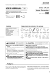
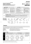
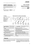
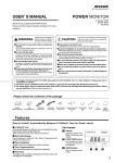
(CSB As of October, 2014 No.2)
The Future of Cyber Gauges is Here and Now.
CYBER GAUGE
USER’ S MANUAL
OBD or SENSOR SYSTEM
Sensor Connection
Thank you for purchasing this PIVOT product.
Please read this manual carefully and keep it for future
reference.
● If this produc t is given to
another user, make sure to
include this User’ s Manual.
Product
Contents
CSB
BOOST
+
Please check the contents of the package
Contents / WARNING / CAUTION ……… 1
Features …………………………………… 2
Part Names and Displays ………………… 2
Connecting The Wires …………………… 2
Installing The Product……………………… 3
Basic Operation …………………………… 3
Switching The Display and Setting ……3~ 4
Troubleshooting …………………………… 4
Pressure
Sensor
Meter
Cushion
Tape
×2
Cut
Connectors
×2
Gauge
Cable
T-Joint
Power Cable
with fuse 3A
Nylon Hose
(2m)
Meter
Holder
I-Joint
Allen
Wrench
Double-sided
Tape
Conversion
Joint
Zip Ties
(Small) × 5
WARNING
Improper use or disregard of
these warnings may result in
the injury or death of people.
●Do not work in areas where there is excessive
exhaust.
Due to vehicle exhaust emission poisoning or fire may
result in a damage to humans.
●Do not crush the cable.
Please be careful that the cable does not get crushed by
the seat rail or car door steel plate, nor cut by any sharp
steel plate as this may cause a poor connection or an
electric short leading to fire or other danger.
●Do not operate while driving.
Operating or checking the display during driving may cause
an accident; please use with the utmost consideration for
safety.
●Please securely fasten the product and be sure
to store bundle away all wires with tape, etc...
It is very dangerous to pull tangled wires by force or allow
tangled wires to interfere with driving.
CAUTION
Rubber
Hose
(5cm)
User’ s
Manual
(This Book)
Improper use or disregard of these warnings
may c ause injur y to per sons, d amag e the
product and other things.
●This product is for DC12V cars;
Installation cannot be carried out on cars with other voltage batteries.
●Just after installation do not exert any strong force on the product.
When double-sided tape is used for an installation be warned that when hot the
tape temporarily losses adhesiveness.
●Do Not Use Chemical Cleansers.
If the unit gets dirty please wipe with a soft cloth to remove any dirt. Do not use
chemical cleansers such as thinner, benzene, or alcohol.
●Do not install the product in any place subject to high temperature or any place where water may be splashed.
●Make sure to replace all screws and parts to their original place.
●Do not install the product in a place where it will cause distraction.
●Do not, in any manner, process, take apart, or make changes to
this product.
Features
Sensor Connection Models
Wide Range Compatible Sensor Connection Models
Illumination
White LED lighting of Dial and Needle.
*Sensors for display is included
Warning and Peak reading
Blinks red LED at the set value as Warning and the Peak reading.
Low Position Holder
New meter gauge holder allows for installation at 5 mm lower
than normal.
Stepping Drive
Our stepping motor is able to provide a smooth, highly precise
display.
1
Part Names and Displays
1 Display
Display BOOST data.
2 LED
Blinks red LED at the set rpm and the Peak reading.
3 Switch
Use to set the warning and
display and reset the peak value.
4 Needle
Shows the current values and peak value.
5 Illumination
Normally illuminated when on display.
(dial : white, needle : white)
Size
1.0
1
2.0
2
BOOST
x100kPa
0
[Unit : mm]
CYBER GAUGE
3
4
-1.0
Pressure Sensor
Meter
15 30
50
ø60
ø65
34
Depth 20
Display Range
Warning
Peak Value
-100 〜 200kPa
Over the set value
Maximum side
Connecting the Wires
BASIC WIRING
Connecting for Boost
How to connect
Meter
① C u t t h e va c u u m h o s e w h i c h c a n m e a s u r e
pressure directly from a surge tank or a intake
manifold in the engine room. (e.g.,the hose
c o n n e c t i n g t o a f u e l r e g u l at o r, a c h a r c o a l
canister, etc.)
3-pin
Connector
Meter
Holder
To the inside
of the car
(1.5 m)
Surge
Tank
Sensor Hose
I-Joint
(1m)
Conversion
Joint
③ Pull the nylon hose to the inside of the c ar
through a wire harness grommet, etc.
Rubber
Hose
④ Using the I-joint, connect the nylon hose to the
unit. (Figure B)
Fuel Regulator,
Charcoal Canister,
etc.
Red
IGN
Black
Earth
T-Joint
Figure B
2. Stretch the hose that comes out from the Pressure Sensor but do not pull it off.
3. If the hose can measure pressure is other than
ø4, please prepare a separately sold joint that
matches the size of the hose.
IGN
Figure A
I-Joint
1. Be sure install the unit on the inside of the car.
(Not in the engine room)
Red
Make sure that all hose and joint connections are
securely fastened so as not to disconnect or
cause pressure loss. (Depending on the conditions, it may be necessary to take some action to
prevent loosening and disconnection of the
various connection points.)
Cut the vacuum hose
which can measure
pressure
2-pin Connector
(1m)
② Insert a T-joint and connect the various hoses
and joints as shown in Figure A.
Nylon Hose (2m)
Wire harness
grommet, etc.
3-pin Connector
Pressure
Sensor
To the engine room
Pressure
Sensor
Nylon
Hose
Hose from
the Pressure
Sensor
Vacuum
Hose
(cut)
Conversion
Joint
To the inside
of the car
Fasten to a screw of a metal
part which is earthed.
with earth
Black terminal
Rubber
Hose
To the engine room
Earth
Connect to the IGN (12V with key ON)
using the cut connectors (included).
(Do not connect to ACC)
T-Joint
Nylon Hose
●Painted screws and screws
connected to plastic parts are
n ot ear t h e d; m ake sure to
connect only to a place which
is earthed.
【Reference】How to use the Cut Connectors
1
10 mm
Peel off of the vinyl
cover at connection.
2
2
10 mm
Peel of f of the vinyl
c ove r at t h e e n d of
the product’ s wire.
3
4
Wrap around both
wire coils.
5
Close tightly with cut
connector.
Insulate with vinyl
tape.
When crimping, please
use crimpers or use
pliers to bend and then
solder together.
Installing The Product
Installing The Meter
(Installation with the Meter Holder)
① Fasten using the double-sided
② After deciding the position
③ Affix Cushion tape on 2 to 4 places to the
tape. (Clean the sur fac e;
removing all oil and dust.)
and angle of the meter
face, fasten the Hexagonal
bolt on both sides to
secure.
base of the meter and install the gauge into
the Meter Holder.
Meter
Holder
Double-sided
tape (Included)
Clean to remove
oil and dust
Double-sided
tape (Included)
*
Please be sure about where you wish to
install the meter, as it is not advisable to
reuse double-sided tape.
●When using Link Cable, put the connector to the
back of Meter Holder as shown in the below diagram.
Push the remained cable between the meters to
inside of Meter Holder.
Meter
Connector
Meter
Holder
Meter
Cable
Hexagonal bolt
Installing the Sensor
(Example of Installation)
Fastening to Flat Space
Pressure
Sensor
Connector
Double-sided
tape
(Included)
Cable
Clean to
remove
oil and dust.
As shown in the above diagram ,
fasten the unit into positions not
usually affected by water.
Basic Operation
1
Key Switch ON
(Engine start)
2
Opening Demo
3
Real-time display
4
Key Switch OFF
(Engine stop)
5
Meter OFF
The needle stops
when the key is
turned OFF.
Opening Demo
●The needle will move to the lowest value side several times for searching position. Then it will move to the maximum value and finally to
reading for current measurement item.
Switching The Display and Setting
Peak reading display
1
Press the switch
once
Reset the Peak reading
1
Pressing the switch while displaying the peak reading
will re-set the peak reading.
While the meter is in operation, press the switch once.
2
Peak reading display
Press the switch
for 3 seconds
4
Reset the Peak reading
LED will light.
LED will light off.
3
Real-time display
5
Real-time display
Back to real-time display after 3 seconds releasing
the switch.
※Each peak value can be reset by the key OFF.
3
Setting of Warning
※Can't make setting of Warning while displaying Peak reading(LED lighting).
1
Press the switch
for 3 seconds
4
Release
the switch
While the meter is in operation, press the switch for 3 seconds.
2
5
Setting warning point display
LED will brink.
3
Press
the switch
While holding down
the switch, change the warning setting.
Real-time display
LED will light off and back to real-time display after
3 seconds releasing the switch.
Each pressing of the
switch will raise, at
the maximum point it
will return to the
minimum point.
※By continually pressing down on the switch the needle will move
to the maximum point.
Troubleshooting
Trouble
Possible Causes
Possible Solutions
Does not work with Engine start.
Po or c o nne c t ion of
Power Cable .
The opening demo starts with Engine start,
but the needle does not work.
Poor connection of the vacuum hose.
Pl e a s e r e c o n f i r m w h e t h e r w i r i n g a n d
connections are correct or not.
Unable to measure pressure.
Please make sure to connect the hose
which can measure pressure.
The opening demo starts on different timing
with the other Cyber Gauges.
Difference of power cable connection.
Please make sure to connect to the IGN
where the other Cyber Gauges connected.
The displayed values are different from the
standard meter.
This product’ s boost meter reads absolute pressure and may differ from a meter using
relative pressure.
G aug e C a b l e ,
Pl e a s e r e c o n f i r m w h e t h e r w i r i n g a n d
connections are correct or not.
※Our products have already been recognized as our Industrial Property or are in the process of receiving Industrial Property status.
※We plan in the near future to take all possible legal measures to protect against unfair competition from look-alike products using similar designs,
regulating characteristics, circuitry and circuitry layout.
※We strictly prohibit the unlicensed use of the PIVOT trademark and the unauthorized use of PIVOT User’ s Manual.
4
PIVOT CORPORATION 87-3, Shimookada Okada, Matsumoto-shi, Nagano, 390-0313 JAPAN
http://pivotjp.com/