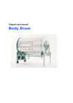
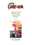
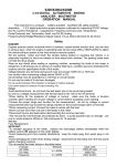
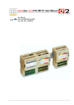
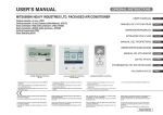
1
USER MANUAL FAT CONVEYOR 1. Declaration of Conformity EU Declaration of Conformity Manufacturer: Address: Jasopels Production A/S tel. +45 76 94 35 00 Hammeren 3 DK-6800 Varde Machine: Type : Fat Conveyor 80-0000 Jasopels Production A/S declares that this product is in accordance with the following EU Directives: 89/336 EEC 98/37 EEC Furthermore, we declare that the following harmonized standards have been applied: EN 60204-1 EN 983 Place and date: Varde, May 1, 2005 Name: Managing Director Janne Jensen User Manual Fat Conveyor_58_80-0000 Ver.1.2.0. Jasopels Knivholtvej 9 9900 Frederikshavn Sales: tel. +45 9843 0566 fax +45 9843 8000 Service: Tlf. +45 9843 9966 Page 2 of 20 2. Table of contents 1. Declaration of conformity ....................... 2 2. Table of contents .................................. 3 3. Preface ................................................. 4 4. Symbol explanation .............................. 5 5. Introduction of the machine .................. 6 6. Start-up ................................................. 7 7. Operation .............................................. 8 7.1 Preparation for start-up ...................... 8 7.2 Setting the timer................................... 9 7.3 Setting the auger speed....................... 9 7.4 When the auger is stuck .................... 10 7.5 Emptying the auger............................ 11 7.6 Removing the auger .......................... 12 8. Maintenance ....................................... 13 8.1 Daily maintenance ............................. 13 8.2 End-of-season maintenance . ............ 13 9. Technical data .................................... 14 10. Circuit diagram................................... 15 11. Spare parts list .................................. 16 12. Troubleshooting ................................. 19 12.1 When the error light is on................. 19 12.2 Poor suction capability ..................... 19 12.3 When there is fat coming out of the air outlet ................................................ 20 12.4 When the FORWARD/BACK functions are not working ................................ 20 Jasopels Knivholtvej 9 9900 Frederikshavn Sales: tel. +45 9843 0566 fax +45 9843 8000 Service: Tlf. +45 9843 9966 Page 3 of 20 3. Preface This User Manual is an important part of your new machine. Read the manual thoroughly and use it as a reference book. This manual contains important information about safety and the correct use of the machine. The manual should be stored with the machine. It is important that the user manual is supplied with the machine upon resale and lending. The user of the machine must make sure that the operator, service personnel and others who have access to the machine have been instructed in the correct use and handling of the machine. Refer to this user manual for further information. Jasopels Knivholtvej 9 9900 Frederikshavn Sales: tel. +45 9843 0566 fax +45 9843 8000 Service: Tlf. +45 9843 9966 Page 4 of 20 4. Symbol explanation Please read this user manual and follow the included instructions. In order to emphasize certain information, the following expressions are used: Note! A triangle containing an exclamation mark is a symbol that warns you of important instructions or information concerning this machine. Danger! A triangle containing a flash of lightning is a symbol that warns you of “High Voltage”. Warning! A triangle warning you of entanglement and crush hazard. Jasopels Knivholtvej 9 9900 Frederikshavn Sales: tel. +45 9843 0566 fax +45 9843 8000 Service: Tlf. +45 9843 9966 Page 5 of 20 5. Introduction of the machine The fat conveyor is designed to transport fat from the BS Teknik fleshing machine to a container. The machine is a combination of the already known fat suction device with an integrated transport unit. One of its many advantages is that it makes it possible to continue the fleshing process while the fat container is being replaced. While developing the fat conveyor’s control system, we have managed to reduce the energy consumption considerably in comparison to previously known systems. We have achieved that by having the conveyor run in a pulse-pause sequence. The machine’s construction makes it very easy to operate it. During normal operation the fat conveyor is controlled via the control panel on the fleshing machine. Note! The user of the machine must make sure that the operator, service personnel and others who have access to the machine have been instructed in the correct use and handling of the machine. Refer to this user manual for further information. The machine may only be used for the purpose it has been designed for. If any problems should occur with the machine or its operation, they must not be fixed before the machine is properly switched off, unless a correction can be made via the machine’s control buttons. The user manual should always be kept available for the operator. Jasopels Knivholtvej 9 9900 Frederikshavn Sales: tel. +45 9843 0566 fax +45 9843 8000 Service: Tlf. +45 9843 9966 Page 6 of 20 6. Start-up Before start-up the machine has to be placed on a firm and stable base. The adjustable feet of the machine need to be adjusted so that the machine is properly leveled up. The machine is delivered with two CEE wall plugs (4- and 7-pin, respectively). The user has to arrange for the installation of the mentioned plugs as well as for the cabling between the fat conveyor and the automatic fleshing machine. The fat conveyor has been equipped with 3 CEE plugs, which are to be connected in the following way: the 7-pin CEE plug is to be connected to the wall socket and used to connect the fat suction device with the startup and surveillance devices in the automatic fleshing machine. the 4-pin CEE plug is to be connected to the wall socket that the automatic fleshing machine uses to monitor and operate the fat conveyor. the 5-pin CEE plug 5 is to be connected to a standard wall socket, 3 * 400 V+N+PE, and protected with at least 16 A. - - - The automatic controller and monitoring system of the fat conveyor is not activated until the included K09 relay has been installed in the PLC cabinet on the automatic fleshing machine. The automatic fleshing machine and the fat suction device have to be connected using a 160 mm suction line. In order to obtain optimal suction, make sure that the line is installed with as gentle swings and rising as possible. Avoid sharp turns right after the fleshing machine. The fat conveyor is now ready to be used. Note! In order to avoid potential damage to the control system’s micro controls and the rest of the machine’s electrical system due to thunderstorms, it is recommended to disconnect the machine from its electrical power source whenever it is not being used. Jasopels Knivholtvej 9 9900 Frederikshavn Sales: tel. +45 9843 0566 fax +45 9843 8000 Service: Tlf. +45 9843 9966 Page 7 of 20 7. Operation 7.1 Preparation for start-up The control buttons on the control cabinet have to be set as follows: - The STOP button must be NOT pressed in. - The MAN- 0- AUTO switch must be set to AUTO. - If the control buttons are not set in the described positions, it will not be possible to start the fleshing machine and the error light on the PLC cabinet will be on. - Make sure that the auger is fastened in the fittings under the cyclone and that the discharge pipe with fire hose has been installed at the end of the auger. The fat conveyor is now ready and you can start the fleshing machine. 5.Cyclone 6. Control cabinet 1.Discharge pipe with bend 6.Styreskab 7. Suctton line 2.Fire hose 8.Muffler 9. Fat suction device 3.Fedtsnegl 3. Fat auger 9.Fedtsuger 10. Air outlet 4.Lock mounting for fat auger 11. Auger motor 11.Sneglemotor Fig. 1. Fat conveyor As the first part of the starting sequence, the star triangle automatic control in the fleshing machine will start the fat suction motor and the pulse/pause timer for the fat auger will be activated. Because of this the auger motor does not run continuously but starts and stops with intervals set on the timer in the control cabinet. Danger ! The machine must never be started when discharge pipe is not installed properly. The cyclone has to be closed at start-up. Never stick your fingers into the fat auger or the fat suction device. Jasopels Knivholtvej 9 9900 Frederikshavn Sales: tel. +45 9843 0566 fax +45 9843 8000 Service: Tlf. +45 9843 9966 Page 8 of 20 7.2 Setting the timer The auger’s pulse/pause interval is set on the timer that is installed in the control cabinet’s lower part, on the left side, see fig. 2.1. 4. VLT/Frequency converter 1.Timer 5. Display 2. Pulse/service time 2. Pulse/ køretid 6. Speed adjustment 3. Pause/idle time 3.Pause/stop time Fig. 2. Control cabinet. Use the top potetntiometer (fig. 2.2) to set the auger’s pulse/service time. The available range of time adjustment is from 5 to 100 sec. Use the bottom potentiometet (fig. 2.3) to set the auger’s pause/idle time. The available range of time adjustment is from 5 to 100 sec. The machine’s timer has been preset to 40 seconds of service time and 100 seconds of idle time. The user can adjust these values if they do not fit into the fleshing rhythm. 7.3 Setting the auger speed Use the adjusting knob (fig. 2.6) on the control panel in the frequency converter (fig. 2.4) to adjust the auger motor’s number of revolutions and with it the fat auger’s speed. The number of revolutions is shown on the display (fig. 2.5) located in the upper part of the control panel. During normal operation the number of revolutions should be set to about 3100 rpm. Jasopels Knivholtvej 9 9900 Frederikshavn Sales: tel. +45 9843 0566 fax +45 9843 8000 Service: Tlf. +45 9843 9966 Page 9 of 20 7.4 When the auger is stuck If the fat auger is entangled with skin or sinew residue, there is a risk of it getting stuck and thereby triggering the electronic overload protection in the frequency converter (fig. 2.4), which will then signalize an Error and stop the fleshing machine. You can try to loosen the jammed objects in the following way: Remove the discharge pipe with bend (fig. 1.1). Set the switch (fig. 3.5) to MAN. The frequency converter will now be blinking and showing an error code on the display (fig. 2.5), which can be read when the door to the control cabinet is opened. 1.1.ERROR 4. OPERATION 2.BAK BACK 2. 5. MAN 0 AUTO 3. STOP 6. FORWARD Fig. Front plate the control Fig. 3. 3. Front plate of of control cabinet cabinet In order to reset the error in the frequency converter, press the RESET button on the control panel (fig. 2.5). The auger will run slightly backwards when you press the BACK button (fig. 3.2). If the objects are severely jammed, the electronic overload protection in the frequency converter will disconnect the motor again. If the frequency converter has disconnected, reset the error. After that you can try to loosen the jammed objects by pressing the FORWARD button. Repeat this procedure until the jammed objects are loosened. If the frequency converter is disconnected repeatedly, you must keep an eye on the motor’s temperature as the motor can easily overheat and get damaged due to this heavy strain. Jasopels Knivholtvej 9 9900 Frederikshavn Sales: tel. +45 9843 0566 fax +45 9843 8000 Service: Tlf. +45 9843 9966 Page 10 of 20 In certain cases the objects may be jammed so severely that it may be necessary to remove the auger (see chapter 7.6). If you suspect that the auger may have frozen, you should try to thaw whatever is jammed with hot water before activating the FORWARD and BACK buttons. After the auger has been emptied, install the discharge pipe again and set the switch (fig. 3.5) to AUTO. 7.5 Emptying the auger After the day’s fleshing work is over, the cyclone and the fat auger should be emptied manually, especially when there is a risk of temperatures dropping below zero at night. This is done in the following way: The fat suction device should not be stopped until all cleaning of the fleshing machine has been finished. Set the function switch (fig. 3.5) to MAN. Turn the speed adjustment knob (fig. 2.6) on the frequency converter clock-wise all the way. This will increase the speed to about 5100 revolutions. Press the FORWARD button until the auger is completely empty. Set the speed adjustment knob back to about 3100 revolutions. Close the cabinet and set the function switch to AUTO. Jasopels Knivholtvej 9 9900 Frederikshavn Sales: tel. +45 9843 0566 fax +45 9843 8000 Service: Tlf. +45 9843 9966 Page 11 of 20 7.6 Removing the auger In certain cases the auger may be so jammed that the jammed objects cannot be loosened by using the FORWARD/BACK functions. In such cases it is necessary to remove the auger. This is done in the following way: Remove the discharge pipe with bend (fig. 1.1). At the bottom of the gear remove the bolt that holds the through-going shaft. The auger can now be removed from the pipe for cleaning. If it is difficult to remove the through-going shaft from the gear, it is recommended to screw a somewhat longer 8 mm bolt to the end of the shaft and knock on it. Pay attention to the little wedge located between the shaft and the gear. After all cleaning has been finished, install all the parts in reverse order. Remember the wedge by the gear. Set the speed adjusting device on the frequency converter (fig. 2.6) to about 3100, close the control cabinet door and set the function switch (fig. 3.5) to AUTO. Jasopels Knivholtvej 9 9900 Frederikshavn Sales: tel. +45 9843 0566 fax +45 9843 8000 Service: Tlf. +45 9843 9966 Page 12 of 20 8. Maintenance DANGER! Disconnect the machine’s power supply before maintenance, cleaning and other services are performed on the machine. It is ESSENTIAL that all 3 CEE plugs are removed from the wall sockets. 8.1 Daily maintenance The daily maintenance is limited to emptying the cyclone and the fat auger, as described in chapter 7.5. 8.2 End-of-season maintenance At the end of the season the inside of the cyclone needs to be washed with a high-pressure washing device. When the clamps at the top and bottom have been removed, you can remove the cyclone from its frame in the hinge mounting. All suction pipes and bends between the fleshing machine and the fat conveyor need to be taken apart and cleaned on the inside so that maximum suction can be maintained. When cleaning is finished, remove the drain plug in order to remove any water that may be left in the fat conveyor. When all the end-of-season cleaning has been finished, store the fat conveyor indoors until the next season. Jasopels Knivholtvej 9 9900 Frederikshavn Sales: tel. +45 9843 0566 fax +45 9843 8000 Service: Tlf. +45 9843 9966 Page 13 of 20 9. Technical data Electrical connection: 5-pin CEE plug 1 X 240V+N+PE Power consumption: Max. 16 A Dimensions: Height: 220 cm Length: 350 cm Width: 80 cm Jasopels Knivholtvej 9 9900 Frederikshavn Sales: tel. +45 9843 0566 fax +45 9843 8000 Service: Tlf. +45 9843 9966 Page 14 of 20 Machine: Fat conveyor 4000vac Drawn by: Date: Drawniing no.: Archive name: Page: To fat auger Fleshing machine 10. Circuit diagram Jasopels Knivholtvej 9 9900 Frederikshavn Sales: tel. +45 9843 0566 fax +45 9843 8000 Service: Tlf. +45 9843 9966 Page 15 of 20 11. Spare parts list 10 8 11 8 12 1 2 3 13 38 4 14 4 5 15 8 6 7 16 8 17 8 18 8 8 9 19 Fig. 4 Fig.Nr. Fig no. 4.1 4.2 4.3 4.4 4.5 4.6 4.7 4.8 4.9 4.10 4.11 4.12 4.13 4.14 4.15 4.16 4.17 4.17 4.18 4.19 Varenr. Item no. 5200-00803120 5200-00803100 5260-12505000 5200-00803130 5200-00803110 5260-11806000 5260-11803090 5260-21805001 5931-10400203 5260-11253030 5260-11253090 5260-11255000 5260-11251050 5290-9104138 5200-00801110 5260-11257160 5200-00801100 5200-00801200 5931-10150214 5935-11490512025 Reservedelsnummer. Spare part no. Ø 250*500mm BU.250.90 TKS.200.250 Ø 250*780mm RCLU 250.180 MFTR 180 BTR 180.90 SB 180 4,00 kW 2800 o/min B3 680v BTR 125.30 BTR 125.90 SB 125 LRTR 125.500 3230101138 I LTR 125 ST 80 L2 1,5KW 2800 o/m LAC 49 -5-120-Ø19-Ø25 Betegnelse Name Længdefalset rør pipe Longitudinally folded Bøjning presset Bend, pressed Spændebånd Clamp Ø250mm Ø250mm Længdefalset rør pipe Longitudinally folded Reduktion centrisk Centrical reduction Tapstykke Pivotal sectionmed with muffemål coupler measurements Bøjning presset Bend, pressed Spændebånd Clamp Ø180mm Ø180mm TRL5555Fan Blæser TRL engine Motor 4kW 4kW Bøjning presset Bend, pressed Bøjning presset Bend, pressed Spændebånd Clamp Længdefalsede Longitudinally foldedrørpipe Spændebånd Ø 104-138mm Clamp Ø 104-138mm Brandslange 5'' 700 mm Fire hose 5’’ 700mm Indløbsrør Påstik Inlet pipe withmconnector Sneglrør komplet 2800mm 2800 mm Screw tubeplastik plastic complete Snegland og feed trækaksel Auger shaft Sneglemotor Auger engine Flangegear gear Flange Jasopels Knivholtvej 9 9900 Frederikshavn Sales: tel. +45 9843 0566 fax +45 9843 8000 Service: Tlf. +45 9843 9966 Page 16 of 20 1 2 3 5 6 7 4 8 Fig. 5 Control cabinet Fig.Nr. Fig no. 5.1 5.2 5.2 5.3 5.4 5.4 5.5 5.6 5.7 5.8 Varenr. Item no. 5922-34001950 5925-44023440 5925-44023410 5922-43109978 5927-14080062 5922-54005040 5921-24000260 5921-24000265 5925-14020030 5925-34022110 Reservedelsnummer. Spare part no. DT10941-1 700 -HN 121 700-HK 36 A 2-4L10A 240V 9623109978 S113-166-230 SIST 500mA 5*20 flink N2-202 M 1,5 Kw N2F-2202A-T for 202 K2-12A01-230V U12/16e 14,0 A 10-14 A5,5kw Betegnelse Name DETransformer transformer 230-230V 50VA DE 230+230V 50VA ABScrew Skruesokkel for 1Pol AB base for 1-pin relay relæ AB relay w.M.lysdiode LED 1P 1P ABMini Minirelæ Electromatic 800800sek. sec. Electromatctimer Timer Fuse holder Sikringsholder Fuse Sikring Taian Converter TaianFrequency Frek. Omform. Taian TaianNetfilter Netfilter B&J B&JContactor kontaktor B&J Overload relayrelay B&JThermo Termo Overload Jasopels Knivholtvej 9 9900 Frederikshavn Sales: tel. +45 9843 0566 fax +45 9843 8000 Service: Tlf. +45 9843 9966 Page 17 of 20 1 2 3 4 5 Fig. 6 Control cabinet door Fig.Nr. Fig no. 6.1 6.2 6.3 6.4 6.5 Varenr. Item no. 5924-74010250 5924-74010110 5924-74010240 5924-74010060 5924-74010050 Reservedelsnummer. Spare part no. B3-MB 230 GRØN B4KN3 B3-MB 230 RØD B4D sort B4P3 rød 28mm Betegnelse Name B&JLED Ledlamp lampe grøn B&J green 240V 240V B&J 1-0-2 B&Jhandle greb 1-0-2 B&J red rød 240V 240V B&JLED Ledlamp lampe B&J head flat black B&Jpress. trykhoved flad sort B&J Red Stop B&Jmushroom-shaped paddetryk Rød Stop Arret. 1 2 3 4 5 6 Fig. 7. Control cabinet door Fig.Nr. Fig no. 7.1 7.2 7.3 7.4 7.5 7.6 7.6 Varenr. Item no. 5924-74010250 5924-74011030 5924-74010240 5924-74011020 5924-74011010 5924-74010160 5924-74010170 Reservedelsnummer. Spare part no. B3-MB 230 GRØN 5924-74011030 B3-MB 230 RØD B3T01 B3M P253-1 B2-B4 Betegnelse Name B&J green 240V 240V B&JLED Ledlamp lampe grøn B&J element 1NO 1NO B&Jplug kontakt element B&J red 240V B&JLED Ledlamp lampe rød 240V B&J element 1 NC 1NC B&Jplug kontakt element B&J element B&Jcoupling koblingselement B&J extension press. baserød red B&J forlængertrykfod B2B4 extension B2B4 forlænger Jasopels Knivholtvej 9 9900 Frederikshavn Sales: tel. +45 9843 0566 fax +45 9843 8000 Service: Tlf. +45 9843 9966 Page 18 of 20 12. Troubleshooting This part shows how some general problems can be solved by the user. This is not an actual description of how the machine as such is to be repaired but simply basic information on how to fix some minor problems so that you can quickly resume fleshing work. In the case of complicated problems, which cannot be fixed by the user, it is recommended to contact the BS Service Department for further assistance. DANGER! Switch off the machine’s power supply before maintenance, cleaning and other service activities are performed on the machine. It is ESSENTIAL that all 3 CEE plugs are removed from the wall sockets. 12.1 When the error lamp is on If a lump is created around the fat auger, it can cause the conveyor to run very slowly and even to stop completely. When this happens, the electronic overload protection in the frequency converter will be activated, which will switch the error lamp on in the front panel of the control cabinet. The frequency converter can be reset by pressing the RESET button on the frequency converter’s control panel (fig. 2.4). If the error is caused by a complete blockage in the fat auger, it needs to be removed as described in chapters 7.4 and 7.6 before fleshing work can be resumed. 12.2 Poor suction capability If the fat suction device’s suction capability is not sufficient, there is a risk that the suction tubes between the fleshing machine and the fat suction device will stop. Reduced suction capability can be caused by: Insufficient amount of vacuum in the cyclone caused by wear/leakage on the bend of the discharge pipe or insufficient tightness of the fire hose at the end of the discharge pipe caused by dirt or ageing. Jasopels Knivholtvej 9 9900 Frederikshavn Sales: tel. +45 9843 0566 fax +45 9843 8000 Service: Tlf. +45 9843 9966 Page 19 of 20 It can also be caused by the fact that the suction device is ”breathing incorrectly”, i.e. if a leakage has occurred in the suction tube between the fleshing machine and the suction device. 12.3 There is fat coming out of the air outlet If the timer’s basic setting has been altered significantly, there is a risk that the fat content in the cyclone becomes too big before the auger starts. The pulse/pause timer (fig. 2.1) should be set as described in chapter 7.2 – to about 40 seconds of service time and 100 seconds of idle time. 12.4 The FORWARD/BACK functions are not working If the FORWARD and BACK functions are not working when the function switch is set to MAN and when it has been confirmed that the overload circuit in the frequency converter has not been activated, you need to examine the following: Is the light in the frequency converter’s display on? If this is not the case, the thermo relay (fig. 5.8) can be disconnected. Press the red button in order to reset the thermo relay. The error can also be caused by a defect in the frequency converter, in which case you should contact the BS Teknik Service Department. If the auxiliary switches (fig. 7.4) have been removed from their fixture (perhaps while the auger’s speed was being adjusted), the FORWARD/BACK function will not work in the manual setting. The auxiliary switches can be pushed back in over the contact element, after which the function can be tested. Jasopels Knivholtvej 9 9900 Frederikshavn Sales: tel. +45 9843 0566 fax +45 9843 8000 Service: Tlf. +45 9843 9966 Page 20 of 20