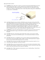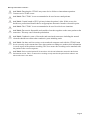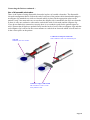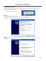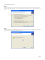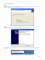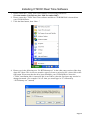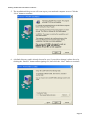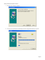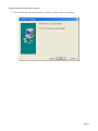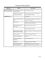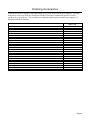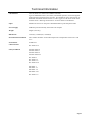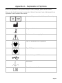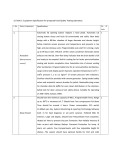
1
User Manual
CT200C
(Electrocardiograph)
Revision:
Release Date:
Manufacturer:
Origin:
4.0
28 November 2007
Macquarie Medical Systems Pty Ltd
Product designed and manufactured in Australia
Contents
Topics
Warnings and Cautions
Introduction
System Requirements
Connecting the CT200C to a notebook computer
Patient Connections
Installing the USB Driver
Installing the CT200C Real Time Software
Running the CT200C Real Time Software for the first time
Main Screen Layout
Recording an ECG Reading
Identify Patient Recording
Save Current Recording
Open Previous Recording
Filtering the ECG signal
Lead Examination Zoom Feature
Copy a Recording to the Clipboard
Handling USB Connection Issues
Detection of inoperable range
Trouble Shooting Guide
Service and Maintenance
Ordering Accessories
Technical Information
Warranty
Appendix A – Explanation of Symbols
Page
3
6
7
8
9
11
14
18
20
22
25
28
29
30
32
34
36
37
38
39
40
41
42
43
Page 2
Warnings and Cautions
Please read the following information before using your CT200C.
DANGER: Risk of explosion if used in the presence of flammable anaesthetics.
DANGER: The CT200C device and its accessories (including electrodes and cables) contain
ferromagnetic materials. As with all ferromagnetic equipment, these products must not be
used in the presence of the high magnetic field created by a Magnetic Resonance Imaging
(MRI) device. The high magnetic field created by a MRI device will attract the equipment
with a force sufficient to cause death or serious personal injury to persons between the
equipment and the MRI device. This magnetic attraction may also damage the equipment.
Consult the MRI manufacturer for more information.
WARNING: The CT200C is an ultra mobile ECG recorder. It is to be used with a notebook
computer running under its own battery power. The notebook computer is used to display
and record ECG data transmitted from the CT200C unit via the USB port connection. The
CT200C has no battery of its own and has to derive power via the USB port connection to
the notebook computer it is connected to. For safety reasons the notebook computer must not
be connected to the mains power at any time while the CT200C is in contact with a patient
via the patient cable leads. Also no other mains powered peripheral devices such as printers,
modems etc are permitted to be connected to the notebook computer while a patient is
connected to the CT200C unit via the patient cable leads. This requirement is to ensure that
the patient is not at risk of any electrical shock or electrocution emanating from the USB
power connection to the notebook computer.
WARNING: No Type B (applied parts) devices are to be used in conjunction with the
CT200C device and its nominated accessories (including electrodes and cables). This
requirement is to protect the patient or user against risk of electric shock or electrocution
emanating from any such third party device.
WARNING: Hazardous conditions may exist if multiple equipment connections are made to
the patient, due to the summation of leakage currents from the multiple devices. Therefore
the CT200C device and its nominated accessories (including electrodes and cables) must not
be used in conjunction with other Type B (applied parts) devices
WARNING: To avoid the risk of electric shock or fire hazard, a multiple portable socket
outlet (MPSO) or extension cord must not be used in conjunction with the CT200C device or
its accessories (including electrodes and cables).
WARNING: Do not operate the unit in the presence of electromagnetic interference.
Interference may be caused by electrosurgery, diathermy, or magnetic resonance imaging
equipment.
WARNING: Use only the defibrillator protected patient cable as supplied by Macquarie
Medical Systems Pty Ltd. Use of a non- defibrillator protected patient cable can cause
damage to equipment or harm to patient or give an incorrect reading.
Page 3
Warnings and Cautions continued …
WARNING: Ensure that when a patient is connected to the supplied defibrillation protected
patient cable that this cable is correctly affixed to the CT200C unit. Ensure that the two
screws that form part of the patient cable are screwed into the screw locks that are on the
CT200C case. This is a critical safety issue to ensure the patients safety prior to defibrillation
or connection to a defibrillator.
Screw locks on CT200C
connector for patient cable
Screws on patient cable
CAUTION: Regularly inspect both the defibrillation protected patient cable and the USB
cable supplied with the unit for any defects such as fraying, cracking or splitting in the cable
insulation. Check for any damage or deformation in the connectors that may cause
intermittent connection between the patient cable and the CT200C unit. Check that these
cables are clean and that the original labelling is legible. If any defects are discovered
immediately discontinue use of the product until replacement parts are available. Please refer
to the “Ordering Accessories” topic in this manual for replacement of parts.
CAUTION: Use only the same brand and type of electrodes at any given time. Do not mix
different brand names or types of electrodes as conductive problems can occur due to
mismatch.
CAUTION: The type of electrodes used can affect the systems recovery from overload,
especially recovery time after defibrillator pulses. Use electrodes that minimise electrode
polarisation.
CAUTION: This device is intended for use by persons trained in professional health care.
The operator must be thoroughly familiar with the contents of this manual before using the
device. This user manual must accompany the device at all time.
CAUTION: Do not operate near high voltage equipment that may generate sparks or in an
environment where high static electricity is present.
CAUTION: Please ensure the patient leads are in the correct locations on the patient’s body,
and ensure that all leads are connected. If it is impossible to connect certain chest leads to the
patient, then connect the unused chest leads to the right leg.
CAUTION: The CT200C should not be subjected to water or liquid spillage. It should only
be used in a dry environment.
Page 4
Warnings and Cautions continued …
CAUTION: Dropping the CT200C may cause device failure or intermittent operation.
Contact service if this occurs.
CAUTION: The CT200C is not recommended to be used on neo-natal patients.
CAUTION: Certain brands of ECG gel may irritate the patient’s skin. If this occurs, the
health care professional should choose an appropriate alternative brand or electrode option.
CAUTION: The CT200C is not recommended to be used in critical care situations.
CAUTION: Do not mix disposable and reusable electrodes together on the same patient at the
same time. This may cause electrode polarisation.
CAUTION: Conductive parts of electrodes and associated connectors including the neutral
electrode should not contact other conductive parts including earth.
CAUTION: The Date and Time settings on the notebook computer used with the CT200C must
be set correctly to the current time zone when patient recordings are made as this information
is saved as part of the patients recording. This is to ensure the recording can be matched with
the patient in the correct sequence.
CAUTION: Each recorded patient ECG must have all relevant information entered in the Patient
Information section. This is to ensure the recording exactly matches the patient from whom it was
taken at the time it was taken.
Page 5
Introduction
CT200C Electrocardiograph
The CT200C Electrocardiograph (ECG) is a simple to use but very powerful ECG recorder. Its
compact size and light weight make it suitable for portable use. It is ideal for use in a clinic or
medical centre or remote field location as it requires only a standard notebook computer running on
battery power alone to display and store the acquired patient ECG signal.
Intended Use
The CT200C is intended to be used on humans as a diagnostic device, which receives records and
produces a visual display of the electrical signal produced by the patient’s heart. The CT200C is not
intended to be used for direct cardiac application, nor during electro-surgery. There is no safety
hazard due to operation of a cardiac pacemaker or other electrical simulators. The CT200C system
has been designed to withstand defibrillation. Read the specific defibrillator user manual before
using the defibrillator in conjunction with the CT200C.
Indications for Use
All devices should only be used by those persons competent in the safe use of patient contact electromedical diagnostic equipment, patient monitoring equipment, and in possession of the
manufacturers’ detailed safe working instructions contained in this manual.
CT200C Electrocardiograph User Manual
This Manual is divided into sections as listed on the contents page (page 2.). In order to use the
CT200C unit there is a requirement to connect it to a notebook computer. It is required that this
computer be installed with the software supplied. The software installation process requires that the
device driver for the USB interface be installed first followed by the Real Time software (RT200).
If you have any difficulties using the unit or the software, and the procedures set out in this manual
do not help you solve your problem; please contact the sales department at Macquarie Medical
Systems:
Website:
www.machealth.com.au/mms
Email:
[email protected]
Phone:
Australian Customers Call: 02 9692 7911
International Customers Call: 612 9692 7911
During Australian Eastern Standard Time Business Hours (GMT + 10:00)
After Hours phone calls will be diverted to Messagebank
Fax:
Australian Customers: 02 9692 7965
International Customers: 612 9692 7965
Page 6
System Requirements
The following table shows the minimum software and hardware requirements needed to install and
run CT200C Real Time Software
Operating System Microsoft Windows 98, SE, Windows 2000, XP & Vista
(Note: Please check the Microsoft website for latest service packs)
Windows 95 & ME are not supported
Microprocessor Celeron 800Mhz or better
Memory 128 MB or better
Hard Disk space 4 MB + 48K for each ECG file.
Disk Drive CD-ROM drive (for the installation disc).
Video Adaptor SVGA monitor
Printer Minimum requirement 300DPI (Dots per inch)
Other 1 free USB Port (used for recording from the CT200C, and powering the
CT200C).
The notebook computer must not exceed a rated voltage and frequency of 240V 60Hz. The
notebook computer is not supplied by Macquarie Medical Systems. The notebook computer should
be located outside the patient environment (see Figure 3) at all times. It is recommended that the
notebook computer used complies with IEC 60950-1.
Figure 1 - Example Patient Environment
Page 7
Connecting CT200C to a notebook computer
Connecting the CT200C
To connect the CT200C to your notebook computer, all that is required is the Universal Serial Bus
(USB) cable supplied with the CT200C. Follow the steps below to ensure you link the CT200C
correctly.
1. Locate a spare USB Port on your notebook computer as shown in the picture below. Connect the
host end (Type A) of the USB cable into a spare USB port.
Figure 2 – Host End
(Type A of USB Cable)
Figure 3 - Type B USB Cable
USB Ports
2. The same USB ports are present on notebook computers and desktop computers. Most computers
will have more than one USB port.
3. Connect the other end of the USB cable to the CT200C as shown below.
USB Port
Patient Cable Port
Page 8
Patient Connections
Electrodes
Good electrode connection is the most important factor in recording a good quality ECG.
By following a few basic steps consistent, clean recordings can be achieved.
1) Ensure patient electrical isolation; do not connect any Type B (applied parts) devices in
conjunction with the CT200C device and its nominated accessories (including electrodes and
cables). This requirement is to protect the patient or user against risk of electric shock or
electrocution emanating from any such third party device. Please refer to the section in this
manual entitled “Warnings and Cautions” for further detail on safe operation of the CT200C
device.
2) Clean the electrode sites with an alcohol swab.
3) Place a small amount of ECG electrode gel on the metal electrode of the
limb strap or clamp. Non-conductive gels (such as ultrasound gel) and
water are not suitable for ECG connections. Where body hair is present at
the electrode sites, use more gel to ensure a good connection. It is not
usually necessary to shave the patient.
4) Connect the electrodes a short distance above the ankle or wrist, with the
metal part placed on the fleshy part of the limb.
5) Place a small amount of gel at each of the chest electrode sites, and attach
the suction bulbs.
Follow the same procedure for disposable electrodes (no gel is required). Disposable electrodes
must only be used once. Re-using these electrodes will always result in poor recordings.
Lead Connections (10 leads on patient cable)
The following lead name abbreviations and colours are used for the electrode leads:
Australia/USA
Europe
Lead Name
Code
Colour
Code
Colour
Right Arm
Left Arm
Right Leg
Left Leg
Chest 1
Chest 2
Chest 3
Chest 4
Chest 5
Chest 6
RA
LA
RL
LL
V1
V2
V3
V4
V5
V6
White
Black
Green
Red
Red
Yellow
Green
Blue
Orange
Purple
R
L
N
F
C1
C2
C3
C4
C5
C6
Red
Yellow
Black
Green
Red
Yellow
Green
Brown
Black
Purple
Page 9
Connecting the Patient continued …
Use of disposable electrodes
There is the option of using disposable electrodes in place of reusable electrodes. The disposable
electrode arrangement that is used on the end of each one of the patient cables 4mm banana plugs is
an alligator clip attached to a stick-on electrode which is placed in the appropriate place on the
patient’s body. One must take care to note how the alligator clip is attached to the stick-on electrode
as there is only one conductive side surface on both the stick-on electrode and the alligator clip.
If you do not make this connection correctly there is no conductive path for the patients signal to
travel. Ensure that all leads are pushed firmly into the backs of each of the ten alligator clips and that
each alligator clip is affixed in the correct manner to each stick-on electrode which is itself stuck on
in the correct place on the patient.
Conductive metal plate with teeth
NB: Conductive side is on the bottom jaw
Top side
Insulated, does not conduct
Conductive edge is underneath
NB: Conductive side is on the
sticky adhesive side
Page 10
Installing the USB Driver
Installing the USB Driver
As soon as you plug in the CT200C to the USB port, your computer will start the “Found New Hardware wizard“ which
will prompt you through the entire device driver installation process, just follow the sequence of dialog screens below
selecting the options as instructed.
First prompt is a message as shown below:
Step 1
The wizard launches with this first screen.
Please ensure the CT200C Installation Disk is inserted into your CD-ROM drive.
On this dialog screen please click option “Yes, this time only” then click the next button.
Step 2
On the following dialog screen please click option “Install from a list or specific location (Advanced)” then click the
next button.
Page 11
Installing the USB driver continued …
Step 3
On the following dialog screen please click option “Search for the best driver in these locations.” Then tick the “Search
removable media (floppy, CD-ROM…)” and if ticked un-tick the “Include this location in the search” then click the next
button.
Step 4
The following dialog screen will be displayed during the operating systems search for the USB device driver. Please wait
until this finishes. (Approximate time taken several seconds)
Page 12
Installing the USB driver continued …
Step 5
The following dialog screen will be displayed during the operating systems search for the USB device driver. Please wait
until this finishes. (Approximate time taken several seconds)
Step 6
On the following dialog screen please click the “Finish” button to complete the process.
This final dialog screen pops up telling you that your hardware has been successfully installed and the CT200C driver is
functional.
Page 13
Installing CT200C Real Time Software
1. Please ensure the CT200C Real Time software version being installed is:(Version number 3.00, Release date: 28th November 2007)
2. Please ensure the CT200C Real Time software and driver CD-ROM Disk is inserted into
your CD-ROM Drive.
3. Click the Start button, then “Run…”
4. Please type in the following text “D:\ RT200setup.exe” in the white entry section of the drop
down list. (Note: This is not case sensitive upper or lower or mixed is fine.), then click on the
OK button. Please note that the drive letter should be your CD ROM Drive where the
CT200C installation disk is inserted if this is not D drive, then the first letter may need to be
changed to match. (For example if it is E: then you would type in “E” followed by
“:\RT200setup.exe” instead)
Page 14
Installing CT200C Real Time Software continued …
5. The installation dialog screen will come up on your notebook computer screen. Click the
“Next” button to continue.
6. A default directory path is already chosen for you, if you wish to change it please do so by
clicking the “Browse” button and navigating to it, then click the “Next” button to continue.
Page 15
Installing CT200C Real Time Software continued …
7. Click the “Next” button to continue.
8. A screen will very briefly show that displays the files being installed which are required.
Page 16
Installing CT200C Real Time Software continued …
9. Once all the files have been installed, click the “Finish” button to complete.
Page 17
Running the CT200C Real Time Software for the first time
Short cuts are added to you current version of Windows to allow you to click and quickly run the
program. There is an icon on your desktop that can be used or you can use the start button and follow
the path under programs, please refer to these sample images. (Note: Your desktop graphic will vary
from this sample)
Start Button pressed and item selected
Desktop Icon
The programs main screen will open as shown below. Before you can record any ECG, you need to
select and verify the communications. Click on the “Set up” button located on the toolbar, as shown
below
Page 18
Running the CT200C Real Time Software for the first time continued …
On the “General” tab, select communication device “Silicon Labs CP210x USB to UART Bridge”
option, then click the “Link check” button.
If the link check is successful, the following dialog will be shown.
At this point your CT200C is fully operational. Proceed by clicking the OK button in each of these
dialog screens to close them.
Page 19
Main Screen Layout
The Real Time main screen dialog will look similar to the one shown below.
Title bar: At the very top in the title section is displayed the currently open file name along with the
title of this software its current version and to the far right is the minimise, maximize and close
buttons.
Menu bar: Below this is the menu bar, to use it you click on any one item of interest and navigate to
the selected option to activate it. Depending on the current operational status of the program certain
options may be unavailable for change and this will be indicated by the item being greyed out. When
the option becomes appropriate to use it will be un-greyed. Refer figure 2 below to see a sample
view of the greyed out items on the menu bar.
Tool bar: Below the menu bar is the tool bar also sometimes called the button bar, buttons with
icons (small images) displayed on them can be clicked to activate the associated feature. The images
are used as a visual cue to further assist the user of the application. As with many other types of
software running on the Windows operating systems there is the possible use of both the menu bar
and the tool bar items to achieve the same task. The general premise is all features can be accessed
via the text based menu bar where as the tool bar/button bar is generally used for highly repetitious
tasks. Depending on the current operational status of the program certain options may be unavailable
for change and this will be indicated by the item being greyed out. When the option becomes
appropriate to use it will be un-greyed. Refer figure 3 below to see a sample view of the greyed out
items on the tool bar.
Status Bar: At the very bottom of the main screen dialog is the status bar which is used to display
various messages associated with the programs current operations and such information as capitals
lock (CAP), number lock (NUM) and scroll lock (SCRL).
Title bar
Menu bar
Tool bar
Main Screen Dialog
Status bar
Page 20
Main Screen Layout continued …
Figure 2.
Example: Menu bar items greyed out.
Note: Items Undo, Cut and Paste greyed out
Figure 3.
Example: Tool bar items greyed out.
Note: All button items greyed out except Patient Info, About and Record
Page 21
Recording an ECG Reading
The Real Time main screen dialog will look similar to one of these shown below, the screen image in
figure 1 below shows the twelve leads plus the selected rhythm lead view, and the screen image
shown in figure 2 below shows the selected single lead view.
Figure 1
Figure 2
Page 22
Recording Screen Layout continued …
Before you start a new recording, switch to the view you want to use by clicking the “View Real
Time Format” button on the tool bar, as shown below. This button toogles between the two possible
settings, when the button appears to be depressed the view will be in 12 lead monitor mode and when
it appears as un-depressed it will be in single lead monitor mode.
Toggle button between 12 lead viewing and single lead viewing
Once the patient is connected to the unit and they are lying still, click the “Record” button on the
tool bar to bring up the continuous stream on the notebook computer screen. Once you are happy
with the recording either click the “Record” button again or click any where on the main screen to
also stop and complete the recording. At this point in time if you try to make another recording you
are presented with a message screen with the option to either save or dicard the current recording just
made.
Page 23
Recording Screen Layout continued …
If you decide to discard then all information acquired will be lost but to save the current recording
there are several ways, which are as follows:•
By clicking the “File” option on the menu bar and navigating to the “Save” or “Save As…”
options, and selecting one of them
Save and Save As…
button on the menu bar
•
The other way is by clicking the save button on the tool bar menu
Save button on
the tool bar
After you have decided you want to save the file you have to enter the associated patient details if
you have not already done so. Please refer to the topic “Identify Patient Recording” in the next
section in this manual for assistance on this.
You will then be required to finally save the recording Please refer to the topic “Save Current
Recording” in the next section in this manual for assistance on this.
Page 24
Identify Patient Recording
Whenever any new patient recording is created, it must have all relevant information entered with it
to identify which patient it belongs to and at what time the recording was taken. This is a
requirement, and the information must be entered by the qualified person taking the ECG recording.
Please refer to the section “Warnings & Cautions” towards the beginning of this manual.
The dialog screen “Patient Information” containing information fields shown below is automatically
launched when a new recording has been made or when the “Patient Info” button is pressed on the
main screens toolbar.
Patient Info button
on main screen,
allows manual
opening of dialog
screen
Note: Shaped mandatory
fields that must be filled in.
There are five mandatory fields that must be filled in as they will help to reduce the risk of
inadvertently misidentifying the current patient with their particular recording. It is critical this
information be filled in correctly when a recording has been taken. Even if you make a recording that
you are not satisfied with, the five fields Patient ID, Patient Name (Both Surname and Given Name),
Patient Sex and the Doctors Name taking the ECG recording must still be filled in. Below is the
message that you will be prompted with if any of these fields are not filled in.
Page 25
Identify Patient Recordings continued …
Looking again at this patient information dialog screen you will notice a button labelled “Clear”.
When this button is clicked it will clear all currently entered information and restore the default text
that appears initially when a new recording requiring patient information to be added is first created.
Note: You do not have to use this button if you make a mistake in entry in any of the fields that you
are currently entering data in, as they can be manually corrected by clicking the mouse in them and
navigating and typing the correction. It is intended to clear or remove all the information entered at
once.
Note all fields cleared of information
and only certain fields restored with
default values.
Default fields with values restored
When a new recording has been made and you attempt to close the program before you have entered
the patient details that must be associated with it, you will received the following message dialog
screen which will force you to either save and enter the required patient information details or allow
you discard the information recorded if it is unwanted.
Page 26
Identify Patient Recordings continued …
In the following circumstances you will receive the message screen prompt asking if you wish to
discard the ECG data you have currently acquired.
• When you attempt to change from single lead trace to twelve lead trace view or visa versa
without first saving the current patient recording.
• When you have made a recording without saving it and then you try to make another
recording.
Page 27
Save Current Recording
When you confirm that you want to “Save” the recording you will be presented with the Save dialog
screen which will allow you to select a path and enter a file name for your recording. This will save
the file to disk in the path entered for future retrieval.
To make saving more convenient you can set a default path where your recordings are to be saved to
without having to navigate and retype over and over again. To access this feature select “Edit” from
the menu bar and then navigate to the “Options…” item.
Select Options… item
Then click option “Set as below” then click “Browse” and navigate to the path you wish to use, then
click the “OK” button.
Steps
1.)
2.)
3.)
Page 28
Open Previous Recording
To open a recording previously made there are several ways, which are as follows:•
By clicking the “File” option on the menu bar and navigating to the “Open” option and
selecting it.
Select Open… item
•
Or the other way is by clicking the open button on the tool bar menu
Open button
An Open screen dialog will appear prompting you for the recorded file you wish to open. Please
navigate to it and click the Open button at the bottom of this screen. The file will then be opened on
screen.
Page 29
Filtering the ECG signal
Filters (Standard)
On the menu bar at the top of the main screen there is a drop down list box that allows you to select
one of two possible options for the filter setting being applied to the ECG signal data. There are two
possible settings which are 40Hz (Normal) or 100Hz (Clinical). By setting the filter to 40Hz, most
high frequencies above 40Hz including power line and muscle artefact will be removed. Note that
this setting is actually the "Exercise ECG" bandwidth and is normally not used in clinical
diagnostics. Rather than using the lower filter setting to improve the recording environment it is
recommended that the 100Hz setting be used, please note that the default setting used is the 100Hz
clinical filter.
Click the down arrow to open the list portion then click on the filter value you want.
Select by clicking on the
down arrow button then
navigate to the filter setting
and click on it.
Additional Digital Software Filtering
In a very noisy recording environment, it is possible to enable the additional digital software filtering
option to further smoothen the ECG recording.
Step 1
To access this option select the “Edit” menu item on the main screens menu, a drop down menu will
then appear, select the “Options…” item and the RT200 Setup options dialog screen will appear
Page 30
Filtering the ECG signal continued …
Step 2
Click on the “Advance” tab at the top of the dialog screen, then place a tick in the white tick box
labelled “Apply additional software filter to ECG data after recording” and then click the “OK”
button. This setting will now be selected and this dialog screen will close.
Disengage Additional Digital Software Filtering in the presence of a Pacemaker
Please note that the above mentioned digital real time filter option must not be used when the patient
being recorded has a pacemaker fitted. Please ensure that you follow steps 1 & 2 shown above, but in
step 2 un-tick the option labelled “Apply additional software filter to ECG data after recording”.
Also ensure that the standard 100Hz filter option is selected.
Option de-selected
Page 31
Lead Zoom Examination Feature
Once an ECG recording has been made you can more closely examine each lead in detail by moving
the mouse over the lead of interest then double clicking on it.
For example if we click in the vicinity of V3 a new “Zoom View” window will launch as shown
below
Page 32
Lead Zoom Examination Feature continued …
This zoom view window has Sensitivity as well as Speed buttons at the top that when clicked change
the scaling of the lead to match.
There are also vertical and horizontal scroll bars to allow you to move around the image so it can be
viewed in detail when parts lie outside the visible region of this screen.
Vertical Scroll Bar
Horizontal Scroll Bar
By scrolling to an area of interest and changing sensitivity and speed a much more detailed
examination of the lead can be made. Example: Zoom of above lead, at 20mm/mV & 50mm/sec is
shown below.
Page 33
Copy a Recording to the Clipboard
The current ECG recording can be copied to the Windows clip board in the format of a Windows
metafile so that it can be pasted into other Windows applications that are clipboard enabled. There
are two ways to activate the copy feature, one way is to click the button on the main screens toolbar
and the other is to select from the menu bar and navigate to the “Copy” item, this can be located at
the top of the same main screen.
Menu bar Button
Access via menu
This is an example of an actual ECG recording which has been created, copied and pasted into this
document. For information on how to paste the copied ECG recording in other Windows software
please refer to the help section that is associated with that specific product.
Untitled
=
I
aVR
V1
V4
II
aVL
V2
V5
III
aVF
V3
V6
Rhythm II
Recorded: Fri Nov 23 16:22:01 2007
Patient ID:
Name:
Gender:
DOB:
W eight:
Height:
BP:
007
Doe, Jane
Female
01/30/80
50 kg
160 cm
80/120
RT200 Version 3.00
Scale: 10mm/mV Speed: 25mm/s Filter: 100Hz
Doctor: Dr Healthy
Comments and Medications:
NSR
Cardiologist:
Comments:
Results must be verified and confirmed by a Cardiologist
Page 34
Copy a Recording to the Clipboard continued …
Exporting the recording to disk
The current ECG recording can be saved as a Windows Metafile to disk. This enables the scaleable
Vector graphic image of the recording to be physically saved to a location somewhere on a disk
drive, which may be preferred instead of using the copy feature to the Windows clip board which is
only in temporary memory. To access this feature please select “Edit” from the menu bar on the main
dialog screen and navigate to the “Export” item.
You will be presented with the “Export ECG trace…” dialog screen, please enter the appropriate
path and file name of you choice before committing the file save.
Page 35
Handling USB Connection Issues
Sometimes situations arise that may break the physical connection between the CT200C and the
Notebook computer that the Real Time software is running on. Such things as the USB cable being
removed for example. In these situations the user would receive the following sequence of events
A message screen dialog will appear stating what relevant communications port the CT200C was
previously connected to prior to the disruption.
The current ECG information will be lost and when you go to make another recording you will be
prompted with a message screen dialog prompting you that there is no valid port connected. Click
the OK to proceed.
You will then be presented with the RT200 Setup options screen dialog with the “General” tab
already selected. You must reselect from the list the correct device driver so the communications
link can be re-established. You can also click on the “Link check” button to perform an automatic
check to see if the software can recognise connection. Once connection is re-established you can
continue recording.
Page 36
Detection of inoperable range
When an ECG signal being detected by the CT200C unit is found to be in an inoperable range the
signal is deamed to be invalid. The RealTime software will display the following message
“Inoperative Electrocardiograph” to indicate to the user that this situation is currently occuring.
All ECG trace information on the screen will be erased and no trace will be visible until the return of
a valid signal. This is required to prevent invalid information being supplied to the user that would
be clinically misleading. Such issues as poor patient connection can cause this problem. Please refer
to the topic “Patient Connections” in this manual for further detail.
Page 37
Trouble Shooting Guide
PROBLEM
CAUSE
The measured pulse rate
does not match the rate
printed on the recording
The measurement did not
reach its final value before the
recording started.
Wait until the displayed pulse rate is stable
before starting a recording.
The patient moved during the
recording or the quality of the
recorded ECG was poor.
Check the conditions below. The CT200 may not
measure the rate correctly if it cannot "see" a
good ECG signal on Lead II.
The patient's skin is not clean
Wash with alcohol or soap and reapply ECG
Electrode Gel
The suction bulbs or limb
straps have built up a residue
of gel.
Wash with alcohol or soap after each use. Very
dirty electrodes may need to be cleaned with a
metal polish or replaced.
Disposable electrodes have
been re-used.
Do not use disposable electrodes on more than
one patient. If an electrode falls off, make sure it
is still "sticky" before replacing it.
Electrode terminals are loose
or in poor contact with the
patient leads
Tighten the terminals and make sure that the
electrical connections are clean.
Limb straps are loose
Tighten the straps so that the electrodes are
held firmly against the patient.
The patient moved or spoke
during the recording or the
patient is tense (not relaxed)
Make sure that the patient is warm and comfortable, and ask them to relax during the recording.
Not enough ECG electrode gel
has been applied
Apply more gel to the electrodes. Use extra gel if
there is hair at the electrode sites.
Disposable electrodes have
dried out during storage
Check the "Use By" date and replace electrodes
if required.
X-Ray, diathermy or other
equipment are causing
interference
Switch off the interfering equipment or use the
CT200C in another room.
A metal bed is causing
interference
Make sure that the bed is grounded. If not, ask a
biomedical technician to ground it
The patient cable is faulty
Replace the cable (Refer: Ordering Accessories)
The CT200C is faulty
Call for service (Refer: Service and Maintenance)
The quality of the
recorded ECG is poor
SOLUTION
Page 38
Service and Maintenance
Maintaining the CT200C
The CT200C needs no special maintenance for reliable operation.
Suction bulbs and limb straps should be cleaned after each use with warm soapy water. Electrodes
with a build up of gel or corrosion can be cleaned with a metal polish, but may need to be replaced
for best results. Patient cable connectors should be cleaned with alcohol after each use. The USB
cable is a standard off-the-shelf USB cable. Cleaning should be as per the manufacturer’s advice.
Clean the CT200C unit using a soft dry cloth. If it still is not clean, apply a small amount of nonammonia, non-alcohol based, mild non-abrasive detergent onto a clean, soft, lint-free cloth, then
wipe the surface. Take care to avoid any fluid ingress into the unit.
Cleaning requirements of third party notebook computer and peripherals
Please refer to the instruction manual that came with the notebook computer you are currently using
with the CT200C and follow the manufacturer’s instructions for cleaning this device and its
connected peripherals.
Service
If problems do occur with the CT200C first check the “Trouble Shooting Guide” topic in this
manual. If the problem persists, contact your supplier, an authorised service centre, or Macquarie
Medical Systems at the address below:
Service Department
Dock 2, 35 Moore Lane
(Rear of 35 Moore Street)
Leichhardt NSW 2040 Australia
Phone: +61 02 9692 7911
Fax: +61 02 9692 7965
Email: [email protected]
Web: www.machealth.com.au/mms
European Representative
EC REP
For all enquires please contact our European representative, Medical Technology Promedt
Consulting (known as “MT Promedt”), whose details are as follows:
Authorised EU Representative
Contact Person Dr Michael Rinck
Name Medical Technology Promedt Consulting
Address Altenhofstraße 80, 66386 St. Ingbert, Germany
Phone +49 6894 581020
Facsimile +49 6894 581021
E-mail [email protected]
Page 39
Ordering Accessories
Medical accessories, supplies, and replacement parts can be ordered from your supplier. Use only
medical accessories provided by Macquarie Medical Systems or authorised suppliers of their
products in your local area. For current prices and part numbers please contact your supplier, or
Macquarie Medical Systems:
Order Code
Manuals
CT200C user manual
MANUAL-05
Computer Accessories
CT200C Software/Installation CD
CT200C USB cable
SOFTWA-07
CABLEZ-07
Patient Cables
12 lead ECG cable(European)
12 lead ECG cable(US)
PATCAB-15
PATCAB-16
Electrodes
Disposable electrodes (Packet of 100 pieces)
Alligator clips (Set of 10)
Chest electrodes suction bulbs (Set of 6)
ELECTR-01
ELECTR-02
ELECTR-05
Limb clamp - Adult(Set of 4)
Limb plate - Adult(Set of 4)
Limb straps - Adult(Set of 4)
ELECTR-06
ELECTR-08
ELECTR-09
Limb clamp - Child(Set of 4)
Limb plate - Child (Set of 4)
Limb straps - Child (Set of 4)
ELECTR-07
ELECTR-12
ELECTR-13
ECG Gel (250 ml bottle)
ELECTR-10
Page 40
Technical Information
Classification
Class IIa, Rule 10 in Annex IX of MDD 93/42/EEC,
Type CF Defibrillator Proof, non-sterile, intermittent operation, enclosed equipment
without protection against ingress of water. Not suitable for use in the presence of a
flammable anaesthetic mixture with air or with oxygen or with nitrous oxide. Please
read the section “Warnings and Cautions” for more detail on intended use.
Input
Standard 12 lead US or European coded defibrillation protected patient cable
Power Supply
USB Bus powered internally from notebook computer
Weight
220gm (Unit only)
Dimensions
157mm(L) x 84mm(W) x 38mm(H)
Environmental Conditions
The CT200C should be stored and transported at a temperature between 0°C and
35°C
Performance
Characteristics
AAMI EC11
IEC 60601-2-51
Safety Standards
AS/NZS 3200.1.0
AS/NZS 3200.1.1
AS/NZS 3200.1.2
AS/NZS 3200.2.25
IEC 60601-1
IEC 60601-1-1
IEC 60601-1-2
IEC 60601-2-25
EN 60601-1
EN 60601-1-1
EN 60601-1-2
EN 60601-2-25
IEC 60601-1-4
Page 41
Warranty
MMS warrants that if defects appear in products, under proper and normal use, it will, at its option,
replace or repair the product or refund the purchase price. This warranty is subject to the customer
making a claim in writing to MMS within the given warranty period which starts on the date of the
dispatch of the order.
The standard warranty period of all MMS produced goods shall be 12 months from the
invoice/dispatch date from MMS.
Returned products or the returned parts of any product must be accompanied by an advice note
stating the original invoice number(s) relating to the products and the nature of any claimed defect,
together with such further information as MMS may require.
The warranty does not apply in circumstances where:
1. The goods are not defective;
2. The goods were used for a purpose other than for which they were intended;
3. The goods were repaired, modified or altered by any person other than MMS;
4. The defect has arisen due to misuse, neglect or accident;
5. The defect has arisen due to the incorrect installation of the goods;
6. The warranty seal on the back of the unit has been broken and/or removed;
7. The goods have not been stored or maintained as recommended by MMS; or
8. The customer is in breach of any of these Conditions of Sale.
Due to their nature, cables, connectors and batteries cannot be covered by this warranty.
Where the customer returns products otherwise in accordance with this condition, MMS may refuse
to repair, replace or refund the purchase price of the products and return them to the customer at the
customer’s cost.
No agent or representative of MMS is authorised to make any representations, warranties,
conditions or agreements not expressly confirmed by MMS in writing and MMS is not bound
in any way by such unauthorised statements nor can such statements be taken to form part of
these terms and conditions.
Page 42
Appendix A – Explanation of Symbols
Below is an explanation of the symbols displayed on the packaging, product and accessories.
Please see the “Lead Connections” section under “Patient Connections” topic of this manual for an
explanation of the lead name abbreviations.
Authorised Representative in the European Community
Manufacturer
Temperature Limitation
Caution, consult accompanying documents
Type CF Defibrillator Proof Equipment
Type CF Equipment
Notebook Computer USB Connection
Patient Data
Consult Instructions for Use
Page 43