1
Nicolet Vascular Doc. No. 300/X/11
Issue: 10
User Manual
Auth:
Nicolet Vascular
Pioneer TC8080
and
Companion III
User Manual
December, 2004
Manufactured by:
SciMed Ltd. UK
Nicolet Part Number M7-W001 Rev G
Pioneer TC8080 and Companion III
Init: RN
Preface
Additional copies
Attention
Trademarks
Additional copies of this manual
or other Nicolet Vascular Division of VIASYS Healthcare
literature may be obtained from:
The information in this document
is subject to change without
notice.
Microsoft, MS, MS-DOS,
Windows, Windows NT, Windows 2000, and Windows XP are
registered trademarks of Microsoft Corporation.
Nicolet Vascular Division of
VIASYS Healthcare
P.O. Box 44451
Madison, WI, USA 53744-4451
Nicolet Vascular Division of
VIASYS Healthcare makes no
warranty of any kind with regard
to this material, including, but not
limited to the implied warranties
of merchantability and fitness for
a particular purpose. Nicolet
Vascular Division of VIASYS
Healthcare assumes no responsibility for any errors that may
appear in this document. Nicolet
Vascular Division of VIASYS
Healthcare makes no commitment
to update nor to keep current the
information contained in this
document.
Pioneer, Companion, and
WinTCD are trademarks of
Nicolet Vascular Division of
VIASYS Healthcare.
No part of this document may be
copied or reproduced in any form
or by any means without prior
written consent of Nicolet
Vascular Division of VIASYS
Healthcare.
PR-i
Pioneer TC8080 and Companion III User Manual
Nicolet system
warranty
Nicolet Vascular Division of
VIASYS Healthcare warrants that
each product we sell you shall
conform to its product specifications as defined in the user
documentation.
If the product does not function as
warranted during the warranty
period, we will repair or replace it
without charge. If in our judgment we are unable to do so, you
may return it to us and we will
refund your money.
Warranty period
The warranty period is as stated in
the original quotation, bid or
tender, or terms and conditions
governing the purchase and
installation of the product. If you
install the product, the warranty
period begins on the date of
invoice. If we install the product,
the warranty period begins on the
date of installation but will begin
no later than 30 days from the
date of invoice.
The warranty period in the U.S.A.
is 12 months from the date of
installation The warranty period
for products sold outside the
U.S.A. and Canada is 12 months
from the date of installation or 14
months from the date of shipment,
whichever is less.
PR-ii
Limit of warranty
Misuse, accident, modification,
unsuitable physical or operating
environment, improper maintenance, or damage caused by a
product for which we are not
responsible may void the warranty.
Certain components may have
separate warranty periods as
stated in the product user documentation. Consumables are not
covered under warranty.
THIS WARRANTY REPLACES
ALL OTHER WARRANTIES,
EXPRESSED OR IMPLIED,
INCLUDING THE IMPLIED
WARRANTIES OF MERCHANTABILITY AND FITNESS FOR A PARTICULAR
PURPOSE AND ANY OTHER
OBLIGATIONS OR LIABILITIES ON THE PART OF
NICOLET WHETHER IN
CONTRACT, WARRANTY,
NEGLIGENCE OR OTHERWISE. NICOLET SHALL NOT
BE LIABLE FOR AND DISCLAIMS ALL CONSEQUENTIAL, INCIDENTAL AND
CONTINGENT DAMAGES.
Items not covered by
warranty
We do not warrant uninterrupted
or error-free operation of a
product.
We provide certain non-Nicolet
products on an “as is” basis.
Non-Nicolet manufacturers or
suppliers may provide their own
warranties to you.
Separate software warranty is
provided with software user
documentation.
Preface
Nicolet software
warranty
Nicolet Vascular Division of
VIASYS Healthcare warrants that
the physical media (e.g. diskettes),
shall be free of malfunction in
labor and materials for a period of
ninety (90) days from the invoice
date. If the physical media
containing the software is
defective, Nicolet will replace it
without charge.
This is your sole remedy for
product malfunctions. In no event
will Nicolet’s liability exceed the
price paid for the software,
regardless of the form of the
claim.
Nicolet does not warrant that the
software will operate uninterrupted or error-free.
NICOLET MAKES NO OTHER
WARRANTIES, EITHER
EXPRESS OR IMPLIED, WITH
RESPECT TO THIS SOFTWARE, INCLUDING WARRANTIES OF
MERCHANTABILITY OR
FITNESS FOR A PARTICULAR
PURPOSE. NICOLET MAKES
NO WARRANTY, EITHER
EXPRESS OR IMPLIED, WITH
RESPECT TO THE QUALITY
OR PERFORMANCE OF THIS
SOFTWARE. NICOLET SHALL
NOT BE LIABLE FOR CONSEQUENTIAL, INCIDENTAL OR
CONTINGENT DAMAGES.
Some states do not allow the
exclusion or limitation of implied
warranties or limitation of liability
for incidental or consequential
damages, so the above limitation
or exclusion may not apply to
you.
Software copyright
protection
This software is protected by
state, U.S. and international
copyright treaty provisions. These
copyright provisions apply to your
use of this software regardless of
whether or not you agree to the
following terms. Under law,
copyright infringers may be liable
for actual damages sustained by
the copyright owner and for
punitive damages of up to
$100,000 per infringement.
Unauthorized copying of computer software, and attempts to do
so, are also criminal violations,
with penalties that may exceed
$100,000 in fines and 10 years in
prison.
1. Unless restricted by an
agreement with Nicolet, you
are permitted to:
a. Use this software on only
one computer and by one
user at a time.
b. Make one copy of this
software, provided that:
(i) the copy is created as an
essential step in the utilization of this software in
conjunction with your
machine and that it is used
in no other manner, or
(ii) that the copy is for
archival purposes only and
that all archival copies are
destroyed in the event that
your continued possession
of this software should
cease to be rightful.
c. Sell this software, and any
archival copy, only as part
of the sale of all of your
rights in this software,
except that adaptations so
prepared may be transferred
only with the authorization
of Nicolet.
2. You are not permitted to:
a. Make copies of this software or documentation
except as described above.
b. Alter, modify or adapt this
software or documentation
except as described above.
c. Distribute, lease, rent or
sublicense this software or
documentation.
PR-iii
Pioneer TC8080 and Companion III User Manual
Customer
responsibility
Function And
Intended Application
This product and its components
will perform reliably only when
operated and maintained in
accordance with the instructions
contained in this manual, accompanying labels, and/or inserts. A
defective product should not be
used. Parts which may be broken
or missing or are plainly worn,
distorted or contaminated should
be replaced immediately with
clean, genuine replacement parts
manufactured by or available
from Nicolet. The responsibility
of Nicolet for a malfunctioning
product is limited by the warranty
set forth in this manual. Should
repair or replacement of this
product become necessary after
the warranty period, the customer
should seek advice from Nicolet
prior to such repair or replacement. If this product is in need of
repair it should not be used until
all repairs have been made and the
unit is functioning properly and
ready for use. The owner of this
product has sole responsibility for
any malfunction resulting from
improper use or maintenance, or
repair by anyone other than
Nicolet, and from any malfunction
caused by parts that are damaged
or modified by anyone other than
Nicolet.
The Pioneer TC8080 system and
the Companion III system are
advanced Transcranial Doppler
(TCD) ultrasound systems which
run the WinTCD software
package allowing non-invasive
assessment of blood flow velocities throughout the body. This
method of measurement is
particularly useful for examining
the major arteries supplying blood
to the brain.
TCD is useful for evaluation of
numerous neurologic vascular
problems such as vasospasm and
intracranial stenosis. TCD is also
extremely valuable for intraoperative monitoring to help detect
sudden changes in flow and
potential embolic events. Emboli
are small particles of foreign
matter (air, particulate, thrombin,
etc.) within the bloodstream that
can potentially cause obstructions
in various arteries in the body and
the brain. Such obstructions can
often lead to stroke.
The following non-invasive
methodologies are included:
• Diagnostic cerebrovascular
and extracranial investigation.
• Extended-term unilateral,
bilateral, and multilateral
cerebrovascular monitoring.
• Microvascular studies.
PR-iv
The systems can be used for the
following applications:
• Intracranial stenosis.
• Detection of vasospasm due to
subarachnoid hemorrhage.
• Detection of arteriovenous
malformations (AVMs).
• Assessment of collateral
pathways.
• Document important sudden
changes in flow velocities.
• Track and establish trends of
flow velocities during drug
administration in the operating
room.
• Help improve surgical techniques through immediate
feedback of the results of
interventional procedures,
including the study and
documentation of possible
microemboli which may result
in stroke.
• Demonstrate the resulting
effects of new or experimental
drugs on intracranial blood
flow velocities.
• Document the informative
results of CO2 reactivity
testing.
• Evaluate flow velocity profiles
inside vessels during neuro or
vascular surgery by placing
microvascular transducers
directly on vessels.
Preface
System Comparison
The Pioneer TC8080 system and
the Companion III system are
essentially identical in their
intended applications. The main
difference between the systems is
that the Pioneer TC8080 system is
intended as a desktop or cart
based system and the Companion
III system is designed as a
portable system.
The Pioneer TC8080 system is the
top of the line product including a
few extra capabilities and more
room for expansion.
The Companion III system
provides the portability but is
subsequently limited in capabilities and future expansion.
The following sections describe
the individual system features
providing information on the
system specific features.
Companion III System
Design
Pioneer TC8080
System Design
The Nicolet/EME Companion III
is a completely self-contained,
truly portable Transcranial (TCD),
extracranial and peripheral
vascular Doppler system that
quickly goes where your practice
needs it: Office, Clinic, Hospital,
or Home.
The Nicolet/EME Pioneer
TC8080 is the flagship
Transcranial (TCD), extracranial
and peripheral vascular Doppler
system that is intended for the
non-portable vascular lab or
clinical environment looking for
high end performance.
System Specific Features:
System Specific Features:
• Portable system with integrated
TFT Display - for mobile
applications.
• Desktop system with external
high resolution monitor or TFT
Display.
• Touchscreen display for faster,
simpler on-the-spot operation.
• Optional laboratory cart.
• Two integrated transducer
sockets allowing up to two
probes to be used simultaneously.
• Four integrated transducer
sockets allowing up to four
probes to be used simultaneously.
• Dual frequency capability.
• Integrated medical grade
power supply to allow portable
examinations to save the data
without the need for an
additional isolation transformer.
• Integrated isolation transformer
to allow the display and printer
to be powered without the need
for an additional isolation
transformer.
• Advanced processor.
• Extra PCI slots for future
expansion.
PR-v
Pioneer TC8080 and Companion III User Manual
Features and Benefits
Features
Benefits
Renowned EME high sensitivity
1.6 and 2 MHz pulsed wave
Doppler probes.
• Locate signals in the toughest patients and deepest areas.
Combined pulsed and continuous
wave Doppler in the 4 and 8 MHz
probes.
• For increased utility throughout the body.
Microvascular 16 MHz and 20
MHz option.
• Allows intraoperative microvascular flow evaluation. Autoclavable
1.5mm and 2.0mm transducers are available.
MDD-Mode.
• Allows more data to be interpreted in a simple fashion. Can aid as a
window finder to locate signal on difficult to insonate patients. Can
aid in the identification of embolic events. View a greater number of
vessel segments for a wider field of view. All Doppler signals from
all channels are always available for review and analysis.
Unique SoundTrak™ software
option.
• Saves what you hear. Exact digital sound reproduction, critical in
evaluating suspected embolic events, for all active channels simultaneously even in MDD-Mode operation. Now also available with the
Continuous SoundTrak option enabling the recording of complete
examinations eliminating the need for an external DAT recorder.
Advanced monitoring and
trending program option.
• For complete records, and sophisticated research protocols. Extremely
flexible with analog input & output capabilities.
Advanced H.I.T.S. Indicator.
• For more precise automated indicator of embolic signals. Clinically
demonstrated to be on par with the human observer.
Multi-depth capabilities.
• Advanced multi-segment vessel interrogation, improved emboli
indication.
Easy to use, comprehensive
remote control.
• All control functions are at the user's fingertips.
Wireless remote control option.
• Improved convenience and fewer cords to tangle.
User programmable function keys
on the remote control and
footswitch.
• For convenience and flexibility. Suited to individual users.
PR-vi
Preface
Features and Benefits (continued)
Features
Benefits
NicVue Patient administration and
scheduling software.
• Allows for complete patient management from appointment scheduling to data archiving in an efficient, flexible package.
One-touch text and graphics
reports.
• Allows fast review, interpretation and documentation.
On-line signal post processing
for improved data presentation.
• Quick on-the-fly adjustment for optimum signal recording.
Powerful PC Base.
• Simple upgrades, and Windows 2000 / Windows XP compatibility.
Extensive user configuration
options.
• Set the system up to meet your preferences.
PR-vii
Pioneer TC8080 and Companion III User Manual
Intended operator
Structure of Manual
The Pioneer TC8080 system and
the Companion III system are
intended for trained and skilled
personnel in collecting
transcranial data and peripheral
Doppler ultrasound from a test
subject.
This manual is divided up into
two main parts:
The first part consisting of the
chapters with page numbers
beginning with H covers the
hardware related issues for the
Pioneer TC8080 and Companion
III systems.
The second part consisting of the
chapters with page numbers
beginning with S covers the
functionality of the WinTCD
software package which is used
on both systems.
PR-viii
Table of Contents
Regulatory Compliance
H1-3
Precautions
H1-3
Warnings
H1-4
Cautions
H1-7
Ultrasound safety
Factors influencing ultrasound power output
Amplitude
Sample
Scale
H1-8
H1-8
H1-8
H1-8
H1-8
Display of Thermal Index
Cranial Bone Thermal Index (TIC)
Soft Tissue Thermal Index (TIS)
H1-9
H1-9
H1-9
Description of Applied Parts
H1-9
Chapter H1
Safety Summary
This chapter provides information
concerning the safety of the
Pioneer TC8080 and Companion
III systems.
EMC Statement
Chapter H2
Common Hardware
Components
This chapter provides information
concerning the various components and accessories available as
standard or optional with the
Pioneer TC8080 and Companion
III systems.
H1-10
Remote Hand Controller
Infrared Remote Control
H2-3
H2-3
Footswitch
H2-4
Keyboard
H2-4
Pointing Devices
H2-5
Transducers
H2-6
Analog Connection Box
H2-7
Printers
H2-8
Headphones
H2-8
Consumables
H2-8
Standard Pioneer Accessories
Standard Companion Accessories
H2-8
H2-8
Optional Accessories
H2-9
TOC-i
Pioneer TC8080 and Companion III User Manual
Labels and Symbols
H3-3
Rear View of Companion III
H3-4
Front Quarter View of Companion III
H3-5
Connecting Accessories
Connecting the Keyboard
Connecting the Pointing Device
Connecting an External Printer
Connecting the Optional Footswitch
Connecting the Remote Hand Controller
Connecting a Set of Headphones
Connecting USB Peripherals
Connecting the Companion III to a Network
Connecting an External VGA Monitor
Connecting Serial Devices
Connecting Optional Analog Connection Box
Connecting an External DAT Recorder
Connecting the Standard Transducers to the System
Connecting the Microvascular Probes to the System
H3-6
H3-6
H3-6
H3-6
H3-6
H3-6
H3-7
H3-7
H3-7
H3-7
H3-7
H3-7
H3-7
H3-8
H3-9
Chapter H3
Companion III
System
This chapter provides information
concerning the assembly and set
up of the Companion III system.
TOC-ii
Assembling the System
H3-10
Mains Power Supply
H3-11
Apply Power to the Companion III System
H3-11
Table of Contents
Labels and Symbols
H4-3
Back Panel of the Pioneer TC8080
H4-4
Front Panel of the Pioneer TC8080
H4-5
Connecting Accessories
Connecting the Keyboard
Connecting the Pointing Device
Connecting an External Printer
Connecting the Optional Footswitch
Connecting the Remote Hand Controller
Connecting a Set of Headphones
Connecting USB Peripherals
Connecting the Companion III to a Network
Connecting an External VGA Monitor
Connecting Serial Devices
Connecting Optional Analog Connection Box
Connecting an External DAT Recorder
Connecting the Standard Transducers to the System
Connecting the Microvascular Probes to the System
H4-6
H4-6
H4-6
H4-6
H4-6
H4-6
H4-7
H4-7
H4-7
H4-7
H4-7
H4-7
H4-7
H4-8
H4-9
Chapter H4
Pioneer TC8080
System
This chapter provides information
concerning the assembly and set
up of the Pioneer TC8080 system.
Assembling the System
H4-10
Mains Power Supply
H4-12
Apply Power to the Pioneer TC8080 System
H4-12
TOC-iii
Pioneer TC8080 and Companion III User Manual
Chapter H5
Care and
Maintenance of
the Equipment
This chapter provides information
concerning the care and maintenance of the Pioneer TC8080 and
Companion III systems.
TOC-iv
Cleaning the Equipment
Keyboard
Mouse
SVGA Monitor
Printer
Pioneer TC8080 Base Unit
Companion III Systen Box
Touch Screen Monitor
Cart System
H5-3
H5-3
H5-3
H5-3
H5-3
H5-3
H5-4
H5-4
H5-4
Care of Transducers
H5-4
Cleaning Standard Transducers
H5-4
Cleaning the Microvascular Transducers
H5-4
Cleaning the Microvascular Pods
H5-4
Sterilizing 16 MHz and 20 MHz Probes
H5-5
Durability of Probes
H5-5
User Maintenance Companion III
If the Companion III system does not power up
If the pointing device (mouse/trackball) does not work
If the keyboard does not work
If the printer does not work
If there is no sound from the loudspeakers
H5-6
H5-6
H5-6
H5-6
H5-6
H5-6
User Maintenance Pioneer TC8080
If the Pioneer TC8080 system does not power up
If the monitor is blank with yellow Power Saving LED On
If the color on the screen is not uniform
If the picture is fuzzy
If the mouse does not work
If the keyboard does not work
H5-6
H5-6
H5-7
H5-7
H5-7
H5-7
H5-7
Servicing the Instrument
H5-8
Table of Contents
PC Specifications
H6-3
Doppler Specifications
H6-3
Inputs / Outputs Specifications
H6-5
Analog / Audio I/O Specifications
H6-6
System Feature Specifications
H6-6
Regulatory Compliance Specifications
H6-6
Environmental Requirements Specifications
H6-7
Measurements and Weights Specifications
H6-7
Mains Supply Specifications
H6-7
Fuse Rating Specifications
H6-7
Chapter H6
Technical
Specification
This chapter provides technical
specifications for both the Pioneer
TC8080 and Companion III
systems.
Acoustic Output Specifications
Measurement Uncertainties
1.6 MHz 15mm PW Output Table
2 MHz 10mm PW Output Table
2 MHz 15mm PW Output Table
4 MHz PW Output Table
4 MHz CW Output Table
8 MHz PW Output Table
8 MHz CW Output Table
16 MHz 1.5mm PW Output Table
16 MHz 2.0mm PW Output Table
20 MHz 1.5mm PW Output Table
20 MHz 2.0mm PW Output Table
Acoustic Output in IEC 1157 Format
H6-8
H6-8
H6-9
H6-10
H6-11
H6-12
H6-13
H6-14
H6-15
H6-16
H6-17
H6-18
H6-19
H6-20
Accuracy of Values Specifications
Vertical Scale Accuracy
Horizontal Scale Accuracy
Accuracy of Values Tables
H6-23
H6-23
H6-24
H6-25
TOC-v
Pioneer TC8080 and Companion III User Manual
What is WinTCD?
S1-3
Performing Doppler Examinations
S1-3
Mouse commands
Moving the mouse pointer
Selecting an option with the mouse
S2-3
S2-3
S2-3
Using the touchscreen display
S2-4
Keyboard commands
Underlined letter commands
Pull down menu selections
S2-5
S2-5
S2-6
Entering text using the keyboard
Text edit command keys
S2-7
S2-7
Entering text using the mouse and keyboard
S2-7
Using the remote control
S2-8
Using the footswitch
S2-9
Chapter S1
Introduction to
WinTCD
This chapter provides a basic
introduction to the WinTCD
software package which is used
on both the Pioneer TC8080 and
Companion III systems.
Chapter S2
Entering
Commands
This chapter describes the various
methods of entering commands to
your system:
TOC-vi
Resizing a window
S2-10
Moving a window
S2-10
Maximizing a window
S2-10
Table of Contents
Summary - Diagnostic Acquisition Screen Overview
S3-3
Summary - Diagnostic Acquisition Screen Menus
S3-4
Summary - Monitoring Acquisition Screen Overview
S3-5
Summary - Monitoring Acquisition Screen Menus
S3-6
Summary - Diagnostic Review Screen Overview
S3-7
Summary - Diagnostic Review Screen Menus
S3-8
Summary - Monitoring Review Screen Overview
S3-9
Chapter S3
Summaries
This chapter contains brief
summaries of the various screen
displays and remote control key
functions used with your system.
Detailed descriptions follow in
later chapters.
Chapter S4
Starting WinTCD
Summary - Monitoring Review Screen Menus
S3-10
Summary - Screen Control Buttons
Diagnostic Acquisition Mode
Monitoring Acquisition Mode
Diagnostic Review Mode
Monitoring Review Mode
Continuous SoundTrak
S3-11
S3-11
S3-12
S3-13
S3-14
S3-15
Summary - Remote Control Functions
S3-16
Log on to the system
S4-3
Start the program and open (create) a file
Summary of steps
S4-4
S4-4
This chapter describes how to
start the WinTCD software.
TOC-vii
Pioneer TC8080 and Companion III User Manual
Chapter S5
Preparing the
System for
Monitoring
This chapter describes how to set
up the basic screen displays for
Monitoring acquisitions.
TOC-viii
Choose the monitoring mode settings
Set the screen display
Set the Remote Control S1 - S5 key functions
Set the Footswitch functions
Choose the Vessel Labels
Customizing the window sizes
Splitting the windows horizontally
Splitting the windows vertically
Choose the Doppler Parameter Box display
Depth
SV (Sample Volume Length)
Gain
Filter
Ampl (Amplitude)
Power
TIC/TIS
Mean (Mean Velocity)
Sys (Systolic)
Dia (Diastolic)
PI (Pulsatility Index)
RI (Resistance Index)
H.I.T.S.
D-Mean (Delta Mean)
Display the Toolbar
Set the Copy Window
Set the Event List window
Configure the User Defined Event Marker Lists
Set the Trend window
Choose the Trend window curves
Systole
Diastole
Mean
PI (Pulsatility Index)
RI (Resistance Index)
H.I.T.S.
Choose the Trend curves for display and curve colors
Set the Trend curves scales
Choose the external inputs to be displayed
Set the Trend display options
Choose which events will be displayed
Toggle scale sharing
Toggle background grid
Set the Doppler color
S5-3
S5-4
S5-5
S5-6
S5-7
S5-8
S5-9
S5-9
S5-10
S5-11
S5-11
S5-11
S5-11
S5-11
S5-11
S5-11
S5-12
S5-12
S5-12
S5-12
S5-12
S5-12
S5-12
S5-13
S5-14
S5-14
S5-15
S5-16
S5-17
S5-18
S5-18
S5-18
S5-18
S5-18
S5-18
S5-20
S5-20
S5-20
S5-21
S5-21
S5-21
S5-21
S5-22
Table of Contents
Chapter S6
Preparing the
System for
Diagnostics
This chapter describes how to
setup the basic screen displays for
Diagnostic acquisitions.
Choose the diagnostic mode protocol
Activate the transducer(s)
S6-3
S6-4
Set the screen display
Set the Remote Control S1 - S5 key functions
Set the Footswitch functions
Customizing the window sizes
Splitting the windows horizontally
Splitting the windows vertically
Choose the Vessel Labels
Choose the Doppler Parameter Box display
Depth
SV (Sample Volume Length)
Gain
Filter
Ampl (Amplitude)
Power
TIC/TIS
Mean (Mean Velocity)
Sys (Systolic)
Dia (Diastolic)
PI (Pulsatility Index)
RI (Resistance Index)
D-Mean (Delta Mean)
S6-5
S6-6
S6-7
S6-8
S6-9
S6-9
S6-10
S6-11
S6-12
S6-12
S6-12
S6-12
S6-12
S6-12
S6-12
S6-13
S6-13
S6-13
S6-13
S6-13
S6-13
Choose the Doppler colors
Display the Toolbar
Set the Copy Window
S6-14
S6-15
S6-16
Loading a Protocol
S6-17
The Protocol List window
Step and Flow Direction
Vessel label
Transducer column
Depth column
Sample Volume (S.V.) column
Power column
Report Position column
Saved column
Comment column
Cursor bar
Active Step indicator
S6-18
S6-18
S6-18
S6-18
S6-18
S6-18
S6-19
S6-19
S6-19
S6-19
S6-19
S6-19
Saving Doppler/DSP changes to the active Protocol step
S6-20
TOC-ix
Pioneer TC8080 and Companion III User Manual
Connect the transducer(s)
S7-3
Load the channel settings - Monitoring mode only
S7-4
Choose the Protocol - Diagnostic mode only
S7-5
Chapter S7
Performing an
Exam
This chapter describes how to
acquire data from your subject
during an exam.
Set up the acquisition parameters
Selecting and linking channels
Choose the transducer mode (PW/CW)
Choose the flow velocity scale units
Set the flow velocity scale
Adjust the amplitude
Adjust the sample volume depth
Adjust the sample volume length
Sample volume clarification
Original hardware
MK2 hardware
Technical description of the sample volume
Adjust the sweep speed
Turn on the envelope
Adjust the gain
Adjust the zero baseline
Set the filter
Set the direction of blood flow
S7-6
S7-6
S7-6
S7-7
S7-8
S7-8
S7-9
S7-9
S7-10
S7-10
S7-10
S7-11
S7-12
S7-12
S7-13
S7-13
S7-14
S7-14
Turning SoundTrak on/off
S7-15
Turning the speaker on/off
S7-16
Adjusting the audio volume
S7-17
Activating the audio flow separation
S7-17
Activating the audio squelch function
S7-17
Toggling the audio noise reduction
S7-18
Toggling the Boost mode level
S7-19
Toggling the high frequency enhance
Setting the HFE breakpoint
S7-20
S7-20
Viewing the Spectra
S7-21
Continued on next page.
TOC-x
Table of Contents
Saving spectral snapshots
S7-22
The copy window
S7-23
Freezing the display
Enlarging a Frozen window
Moving a Frozen window
S7-24
S7-25
S7-25
Reading calculations from the Parameter boxes
Setting the Delta Mean 100% reference level
Mean (Mean Velocity)
Sys (Systolic)
RI (Resistance Index)
Dia (Diastolic)
PI (Pulsatility Index )
D-Mean (Delta Mean )
S7-26
S7-26
S7-27
S7-27
S7-27
S7-27
S7-27
S7-27
Reading the intensity scale
Adjusting the intensity scale
S7-28
S7-28
Turning Curve recordings on/off - Monitoring Mode only
Intermittent Curve recordings
Turning Intermittent Curve recordings off
S7-29
S7-29
S7-29
Enabling the indicators - Monitoring Mode only
Configuring the indicators settings
Resetting the H.I.T.S. counter
S7-30
S7-31
S7-32
Saving Event Markers - Monitoring Mode only
S7-33
Working With Event Markers - Monitoring Mode only
S7-34
Using Protocols - Diagnostic Mode only
Loading a Protocol
Stepping through a Protocol
Load the next/previous step
Save the active spectral display and load the next step
Print the active spectral display and load the next step
Loading a step manually
S7-35
S7-36
S7-36
S7-36
S7-36
S7-36
S7-37
Chapter S7
Performing an
Exam (continued)
TOC-xi
Pioneer TC8080 and Companion III User Manual
Start the program and open a file for review
S8-5
Set the remote control S1 - S5 key functions
S8-6
Chapter S8
Reviewing the Data
This chapter describes how to
review data which was collected
during an exam.
Reviewing saved spectral snapshots
Resizing the windows
Using the general cursor mode (spectral displays)
Activating the general cursor mode
Recognizing the general cursor mode
Selecting the cursor type
Deactivating the general cursor mode
Setting horizontal velocity cursors
Setting vertical time cursors
Setting dual crosshair cursors
Setting differential velocity cursors
Setting differential time cursors
Working with spectral cursors
Moving cursors
Resizing cursors
Deleting individual cursors
Deleting all cursors
Saving cursors
Displaying cursor units
Clearing cursor background
Hiding cursors
Manually recalculating values
Activating the recalculate values mode
Recognizing the recalculate values mode
Using the recalculate values (2 cursors) mode
Using the recalculate values (3 cursors) mode
Saving recalculated values
Deactivating the recalculate values (2 cursors) mode
Deactivating the recalculate values (3 cursors) mode
Deleting a spectral snapshot
Editing a spectral snapshot
Replaying SoundTrak data
Continued on next page.
TOC-xii
S8-7
S8-8
S8-9
S8-9
S8-9
S8-9
S8-9
S8-10
S8-11
S8-12
S8-13
S8-14
S8-15
S8-15
S8-15
S8-15
S8-15
S8-15
S8-15
S8-15
S8-15
S8-16
S8-16
S8-16
S8-17
S8-18
S8-19
S8-19
S8-19
S8-20
S8-21
S8-22
Table of Contents
Chapter S8
Reviewing the Data
(continued)
Reviewing Continuous SoundTrak Data (M-Only)
Replaying Continuous SoundTrak Data
Altering Display Parameters During C. SoundTrak Playback
Adjusting the Time Position for C. SoundTrak Playback
Jumping the Time Position for C. SoundTrak Playback
Postprocessing Continuous SoundTrak Data
S8-23
S8-24
S8-25
S8-26
S8-27
S8-28
Reviewing H.I.T.S. data (Monitoring Mode Only)
Turning the labeling text off
Viewing the advanced H.I.T.S. information
Show event list statistics
S8-29
S8-29
S8-29
S8-29
The SoundTrak display
Activating the SoundTrak display
Adjusting the SoundTrak data amplitude scale
The spectral zoom box
Adjusting the size and position of the spectral zoom box
Default zoom box positions
Reading in H.I.T.S. records
Reading in H.I.T.S. events
Reading in manually saved records
Saving the default zoom box positions for a saved record
Measuring time differences in the SoundTrak data
Activating the general cursor mode
Setting differential time cursors
Saving differential time cursors
Working with SoundTrak differential time cursors
Moving differential time cursors
Resizing differential time cursors
Deleting individual cursors
Deleting all cursors
Displaying cursor units
Clearing cursor background
Deactivating the general cursor mode
Hiding cursors
S8-30
S8-30
S8-31
S8-32
S8-33
S8-35
S8-35
S8-35
S8-35
S8-35
S8-36
S8-36
S8-37
S8-37
S8-38
S8-38
S8-38
S8-38
S8-38
S8-38
S8-38
S8-38
S8-38
Reviewing Trend data (Monitoring Mode Only)
Saving the trend configuration
Configure the trend curves display
Choose the trend curves for display and curve colors
Set the trend curve scales
Choose the external inputs to be displayed
Set the trend display options
Choose which events will be displayed
Continued on next page.
S8-39
S8-39
S8-40
S8-41
S8-41
S8-41
S8-42
S8-42
TOC-xiii
Pioneer TC8080 and Companion III User Manual
Chapter S8
Reviewing the Data
(continued)
TOC-xiv
Toggle scale sharing
Toggle background grid
Choosing the trend curves time scale display
Jumping to the end/start of the trend data
Scrolling through the trend data
Zooming in on the trend data
Unzooming the trend display
S8-42
S8-42
S8-43
S8-44
S8-45
S8-46
S8-46
Reviewing fast curve data (Monitoring Mode Only)
Saving the fast curve configuration
Configure the fast curve display
Choose the fast curves for display and curve colors
Set the fast curve scales
Choose the external inputs to be displayed
Set the fast curve display options
Choose which events will be displayed
Toggle scale sharing
Toggle background grid
Choosing the fast curves time scale display
Moving fast curve data to end/start of the trend data
Scrolling through the fast curves data
Zooming in on the fast curves display
Unzooming the fast curves display
S8-47
S8-47
S8-48
S8-49
S8-49
S8-49
S8-50
S8-50
S8-50
S8-50
S8-51
S8-52
S8-53
S8-54
S8-54
Saving Event Markers (Monitoring Mode only)
Working With Event Markers (Monitoring Mode only)
Saving Custom Markers
Editing Event Markers
Deleting Event Markers
S8-55
S8-56
S8-56
S8-56
S8-56
Using the general cursor mode (curve displays)
Activating the general cursor mode
Recognizing the general cursor mode
Selecting the cursor type
Deactivating the general cursor mode
Setting horizontal curve cursors
Setting differential time cursors
Setting vertical curve cursors
Setting average curve cursors
Working with curve cursors
Moving cursors
Resizing cursors
Deleting individual cursors
Deleting all cursors
Continued on next page.
S8-57
S8-57
S8-57
S8-57
S8-57
S8-58
S8-59
S8-60
S8-61
S8-62
S8-62
S8-62
S8-62
S8-62
Table of Contents
Chapter S8
Reviewing the Data
(continued)
Saving cursors
Clearing cursor background
Hiding cursors
S8-62
S8-62
S8-62
Calculating the vasomotor reactivity (VMR) (M-Only)
Activating the calculate VMR mode
Recognizing the calculate VMR mode
Using horizontal curve cursors to calculate VMR
Using average curve cursors to calculate VMR
Description of calculate VMR mode
Documenting the VMR results
Deactivating the calculate VMR (horiz. cursors) mode
Deactivating the calculate VMR (average cursors) mode
S8-63
S8-63
S8-63
S8-64
S8-65
S8-66
S8-67
S8-67
S8-67
TOC-xv
Pioneer TC8080 and Companion III User Manual
Chapter S9
Creating
Monitoring
Settings Files
Creating a new Settings file
Assign the probe(s) and channel(s)
Set the parameters and window sizes
S9-3
S9-3
S9-4
Creating a new default Settings file
S9-5
Renaming a Settings file
S9-6
Deleting a Settings file
S9-7
This chapter describes how to
create a new Settings file, delete
an existing Settings file, create a
new default Settings file, and
rename a Settings file.
Chapter S10
Creating
Diagnostic
Protocols
This chapter describes how to
create new Diagnostic protocols
which then can be selected to
quickly set up your system for
Diagnostic acquisitions.
TOC-xvi
Creating a new protocol
Choose the common (global) protocol settings
Choose the probe
Create the protocol step
S10-3
S10-4
S10-5
S10-6
Editing a protocol
Selecting a different probe
Adding new steps
Inserting a new step
Editing a step
Deleting a step
Adding/inserting/editing a step
Editing the common (global) protocol settings
S10-8
S10-8
S10-9
S10-9
S10-9
S10-9
S10-10
S10-11
Saving the edited protocol
Overwriting the original protocol
Creating a new protocol
S10-13
S10-13
S10-13
Creating a new default protocol
S10-14
Loading the default protocol
S10-14
Renaming a protocol file
S10-15
Deleting a protocol file
S10-16
Table of Contents
Cascading multiple windows
S11-3
Selecting a cascaded window for viewing
S11-4
Tiling multiple windows horizontally
S11-5
Tiling multiple windows vertically
S11-6
Maximizing a window
S11-7
Minimizing a window
S11-8
Backing up files
Legends
S12-1
S12-1
Printing the spectral window
S12-3
Printing the trend curves window
S12-4
Printing the fast curves window
S12-4
Printing a text report
S12-5
Printing a graphics report
with defined print positions
without defined print positions
S12-6
S12-8
Chapter S11
Viewing Multiple
Window Screen
Displays
This chapter describes how to
view multiple windows on the
screen display.
Chapter S12
Printing, Exporting,
and Backing Up
Files
This chapter describes how to
print reports, export data, and
back up files.
Exporting Reports to PDF
S12-10
Automatically Saving PDF Reports
S12-11
Exporting SoundTrak data to WAV files
S12-12
Retrieving exported SoundTrak WAV files
S12-13
Capturing Screens
S12-14
TOC-xvii
Pioneer TC8080 and Companion III User Manual
About WinTCD
S13-3
Exam Information
S13-4
Software license upgrade menu
S14-3
Using the infrared remote control
S14-4
Online probe test
S14-4
File Size Limitation Menu
S14-5
16 MHz and 20 MHz probe operation notes
S15-3
Chapter S13
Help Menu
This chapter describes the Help
menu function.
Chapter S14
System Menu
This chapter describes the System
menu function.
Chapter S15
Microvascular
Option
This chapter describes the 16
MHz PW and 20 MHz PW
Microvascular options which have
been designed to allow intraoperative investigations of
microvessels.
TOC-xviii
Table of Contents
Loading color M-Mode settings
S16-3
Creating a new color M-Mode settings file
S16-4
Spectral display window layout
S16-5
Color M-Mode display window
S16-6
Color M-Mode image
S16-7
Highlighting the appropriate window
S16-8
Selecting spectral multi-depth channels
S16-8
Set the M-Mode depth scale range
S16-9
Set the M-Mode depth scale offset (zero)
S16-9
Chapter S16
Using the Color
M-Mode Display
This chapter describes how to use
the color M-Mode display in
conjunction with the multi-depth
monitoring mode.
Adjust the sample volume depth
S16-10
Adjust the sample volume length
S16-10
Adjusting the M-Mode channel bands
S16-11
Adjust the M-Mode display gain
S16-12
Adjust the M-Mode color display range
S16-12
Inverting the color M-Mode velocity scale
S16-12
Toggling the M-Mode flow direction coding
S16-13
Selecting the M-Mode color display palette
S16-14
Toggling the M-Mode display enhancement
S16-15
Freezing the spectral/M-Mode display
S16-16
Saving the spectral/M-Mode display
S16-17
Post processing the color M-Mode display
S16-18
TOC-xix
Pioneer TC8080 and Companion III User Manual
Description of Audio Inputs and Outputs
S17-3
Creating Audio I/O Settings
S17-4
Loading Settings and Protocols with External Connections
S17-6
Using the Record Mode
S17-7
Using the Playback Mode
S17-8
Description of Analog Curve Inputs and Outputs
S17-9
Chapter S17
Using the External
Inputs and Outputs
This chapter describes the external
audio input and output facilities
which allow the Doppler audio
signals to be recorded to an
external DAT recorder and played
back in at a later time. The chapter
also describes the external curve
input and output facilities which
allow analog curve signals to be
interchanged with other systems.
In addition, the Continuous
SoundTrak recording facility is
described.
Creating Curve I/O Settings
S17-10
Defining Analog Curve Input Settings
S17-12
Toggling the Fast Curves Window
S17-13
Configuring the Display for External Curve Inputs
Choose the external inputs to be displayed
Calibrate the external inputs
S17-14
S17-15
S17-15
External Curve Output Calibration
S17-16
Sample Rates (Analog Outputs)
S17-16
Sample Rates (Analog Inputs)
S17-16
Creating Continuous SoundTrak Settings Files
S17-17
Creating Files Containing Continuous SoundTrak Data
S17-18
Keeping Track of File Size
S17-19
Reconfiguring the Maximum File Size
S17-19
Reaching the Maximum File Size
S17-20
Index
Index
TOC-xx
Index-1
Safety Summary
Chapter H1
Safety Summary
Regulatory Compliance
H1-3
Precautions
H1-3
Warnings
H1-4
Cautions
H1-7
Ultrasound safety
Factors influencing ultrasound power output
Amplitude
Sample
Scale
H1-8
H1-8
H1-8
H1-8
H1-8
Display of Thermal Index
Cranial Bone Thermal Index (TIC)
Soft Tissue Thermal Index (TIS)
H1-9
H1-9
H1-9
Description of Applied Parts
H1-9
EMC Statement
This chapter provides information
concerning the safety of the
Pioneer TC8080 and Companion
III systems.
H1-10
Information in this chapter is
subject to change without notice.
H1-1
Pioneer TC8080 and Companion III User Manual
Blank Page
H1-2
Safety Summary
Regulatory
Compliance
SciMed Ltd. is an ISO 9001: 2000
and ISO 13485: 1996 and
CMDCAS approved manufacturer of medical equipment.
The Pioneer TC8080 and
Companion III systems have
been certified and tested by
Intertek Testing Services, ETL
SEMKO, to comply with the
General Requirements for Safety
UL2601-1: 1997, CAN/CSAC22.2 No. 601.1-M90 (ETL listed
and labeled), EN60601-1: 1990 +
A1: 93, A11: 93, A12: 93, A2: 95,
A13: 96, Corrigendum: 94 and
IEC 601-1: 1998 + A1: 91, A2:
95, Corrigendum 95.
The Pioneer TC8080 and
Companion III systems have
been certified and tested by TRL
Compliance Services Ltd. to
comply with the Medical Collateral Standard for Electromagnetic
Compatibility IEC 60601-1-2:
2001 and IEC 60601-1-2-AM1:
2004.
The Pioneer TC8080 and
Companion III systems have
been certified and tested by
Intertek Testing Services, ETL
SEMKO, to comply with the
Collateral Standard: Safety
requirements for medical electrical systems EN 60601-1-1: 2001
and IEC 60601-1-1: 2000.
The Pioneer TC8080 and
Companion III systems are class
IIa products that have been CE
approved to the Medical Devices
Directive 93/42/EEC by Lloyds
Register Quality Assurance
(LRQA) in the United Kingdom,
Notified Body no. 0088.
The degree of protection in the
system against electric shock
conforms to EN60601-1 : 1990.
Precautions
IMPORTANT:
Please read this manual carefully before setting up the
system or before connecting
other instruments. Read and
follow all WARNINGS, CAUTIONS and NOTES provided in
this user manual. To avoid the
possibility of personal injury,
damage to your system or lost
data, observe these safety
precautions during system
operation.
In this manual, two labels identify
potentially dangerous or destructive conditions or procedures:
!
WARNING
The WARNING label identifies
conditions or practices that may
present danger to the patient
and/or user.
!
CAUTION
The CAUTION label identifies
conditions or practices that could
result in damage to the equipment.
Notes: These help you identify
areas of possible confusion and
avoid potential problems during
system operation.
H1-3
Pioneer TC8080 and Companion III User Manual
!
WARNING
This device uses a three wire
power cord with a hospital
grade plug (for international
applications, IEC 601-1 approved plug). The chassis is
earth grounded. For grounding
reliability, connect the device to
a hospital grade or hospital only
receptacle (for international
applications, IEC 601-1 approved receptacle).
Connection of the system to any
mains powered electrical
accessories must be in accordance with IEC 601-1-1 : 2000.
This standard describes the
safety requirements for medical
electrical systems to provide
protection to the patient, the
operator and the surroundings.
The system must be connected
to a mains plug that conforms to
all valid safety regulations.
Do not use extension cords for
the system. Extension cords can
cause ground integrity and
impedance problems.
On the Pioneer TC8080 system,
when an external monitor,
printer, or any other electronic
piece of equipment is connected
to the system, it must be powered through the main system's
power sockets.
H1-4
!
WARNING
On the Pioneer TC8080 system,
there are separate voltage
selectors for the input voltage
and the isolated output voltage.
Particular care must be taken
when selecting voltages and this
should only be carried out with
the mains input cord removed.
It is possible to have 230V
output with 115V selected on
the input or 115V output with
230V selected on the input. Both
voltage selectors should be set to
the same value. The output
frequency will always be the
same as the input frequency.
On the Companion III system,
when an external monitor,
printer, or any other electronic
piece of equipment is connected
to the system, it must be powered via the Portable Isobox. If
not, leakage limits may be
exceeded. The Nicolet Portable
Isobox may be obtained from
the suppliers listed in chapter
H5.
Before use, both the system and
any accessories should be
checked for possible damage.
The mains cables should be
carefully examined. If the
insulation or plug is damaged,
an authorized person should
replace it immediately. Damaged probes should not be used
under any circumstances.
!
WARNING
Improper earthing of the system
can result in an electric shock.
The system must be earthed.
The infrared port on the hand
controller is classified as a class
1 LED (Light Emitting Diode)
device according to International Standard IEC 825-1
(EN60825-1). This device is not
considered harmful, but the
following precautions are
recommended: 1. Avoid direct
eye exposure to the infrared
LED beam. Be aware that the
beam is invisible light and
cannot be seen. 2. Do not
attempt to view the infrared
LED beam with any type of
optical device.
On both systems, when a DAT
recorder is used to record or
playback Doppler audio data, it
must be powered through the
main system's isolated power
sockets (Pioneer only), or via
the portable Isobox (Isolation
Transformer).
Safety Summary
!
WARNING
!
WARNING
The DAT recorder must meet
the standard relevant to your
country: IEC 60065:2001, BS
EN 60065:2002, UL 60065:2003,
CAN/CSA-C.22.2 No 60065-03,
IEC 60950-1:2002, BSEN
60950:2002, UL 60950-1:2002,
CAN/CSA-C.22.2 No 60950-103.
Whilst using the system for an
examination, it is recommended
that no electrical connections be
made to the system other than
those specified in chapters H3
and H4. If this is unavoidable
ensure that the extra connections conform to IEC 601-1-1 :
2000.
Where applicable, a potential
equalization connection point
is provided on the system or
chassis of the device for connection to the corresponding parts
of other devices connected to the
patient. Such connections may
be used to help reduce the
incidence of ground and/or
leakage currents which can
occur through patient connections of devices with separate
grounding systems.
To minimize risk of injury to
patient and/or operator, use
only EME/Nicolet approved
accessories with the system that
are specified in this manual.
When more than one medical
device is connected to the
patient, leakage currents of the
devices are summed together.
Use caution.
Whilst using the system for an
examination, do not touch the
interconnecting cable connectors on the rear panel of the
system, or the non-medical
equipment and the patient
simultaneously.
All nonmedical equipment
connected to this device, such as
printers, must comply with IEC
950 and/or appropriate European Directives.
To guard against possible injury
or damage to the system during
installation, make sure the
system power switch is in the
OFF position until otherwise
instructed.
Do not switch on any system
power until all cables have been
properly connected and verified.
!
WARNING
The casing of the system is,
under no circumstance, to be
removed by any unauthorized
persons, as there are live
components within the system.
Customer service and maintenance must be carried out
exclusively by the manufacturers. See chapter H5 for more
information.
No system repairs or maintenance may be carried out while
an examination is taking place.
When replacing mains fuses,
make sure that only the specified fuses are used (IEC 127
Sheet III). Refer to the Technical Specification in Chapter H6
for the correct rating.
The system is not designed for
use in areas with high relative
humidity. Because of the
restricted protection against
drops and splashes of water, the
system should not be set up
where this is likely to occur e.g.
under infusion stands etc.
H1-5
Pioneer TC8080 and Companion III User Manual
!
WARNING
When using an Isobox isolation
Transformer, ensure that the
voltage selector on the Isobox is
set to the correct voltage before
connection.
If an Isobox isolation transformer is not available for
connecting a mains powered
accessory, the system may NOT
be used.
The system is designed for use
in medical areas only. It must
not be used in areas where there
is a danger of explosion such as
near flammable anaesthetic
gases.
This equipment is not protected
against defibrillation. Remove
the patient to system connection
prior to defibrillation. If
defibrillation is applied to the
patient while connected to the
system, damage may occur.
Test system leakage current
after defibrillation.
!
WARNING
When using the 16 and 20 MHz
microvascular probes with the
system, refer to chapter H5 for
important safety and cleansing/
sterilizing procedures. The 16
and 20 MHz probes are not
sterile as supplied. Before using
them for the first time, ensure
that sterilization procedures are
carried out. The 16 and 20 MHz
probes must be sterilized before
each subsequent use.
The microvascular pods must
not be sterilized. These may be
cleaned using the procedures in
chapter H5.
Inspect transducer assemblies
on a regular basis for possible
damage (cracks which could
allow the ingress of conductive
fluids, cable or connector
damage, etc.). Never use a
damaged transducer.
To reduce risk of injury: Use
proper lifting techniques when
moving or lifting the system
components.
The system should never be
placed directly on the floor.
Follow all safety standards set
by your place of employment.
In all cases, the original data
must be reviewed if a clinical
decision is involved.
H1-6
!
WARNING
Do not use ultrasound intensities greater than 10% for
transorbital examinations.
None of the transducers supplied with the system are
intended for fetal use or pediatric applications.
Depending on your locality,
your computer's battery might
be considered as hazardous
waste. Follow all of your
respective local laws and
regulations for the proper
disposal of batteries and any
other parts of your system such
as monitors, amplifiers, keyboards, electrodes, etc.
Federal law in the U.S.A. and
Canada restricts this device to
sale by or on the order of a
medical practitioner licensed by
the law of the state in which
they practice to use or order to
use this device.
This equipment is not protected
against loss of mains power. The
use of an UPS is recommended
to avoid losing data.
Safety Summary
!
CAUTION
Preventative maintenance does
not require access to the interior
of the instrument and may be
performed by the user. For this
device, preventative maintenance
consists of periodically cleaning
and inspecting the exterior of the
instrument. Periodic electrical
safety testing is recommended. It
is recommended a schedule be
established for these purposes,
with at least an annual cleaning
and safety testing. This system
does not require calibration.
Turn off the system power before
cleaning. Prevent detergent
solution or cold sterilization agent
from seeping into the electronics
of the system. Be especially
careful around controls, the TFT
touchscreen display (Companion
III), connectors and panel edges.
Do not use abrasive cleansers.
On the Companion III system,
wipe the TFT touchscreen display
lightly with a soft lint-free cloth.
If necessary, a small amount of
mild detergent may be used. Do
not use any type of abrasive pad,
scouring powder or solvent.
!
CAUTION
Switch off system power before
connecting or disconnecting any
system component(s) or accessories. You may damage the
device(s).
If you disconnect cables, please
be careful to reconnect them in
their proper locations.
To guard against damage to the
system when using the audio
inputs, make sure that the input
voltages, going to the system via
the analog connection box, do not
exceed 10 Vpp.
!
CAUTION
Follow the Shutdown sequence
described in this guide to turn off
the system to ensure the integrity
of your data files.
Leave at least 30 seconds between
turning off the system using the
Power Switch, and switching it
back on.
The customer is responsible for
maintaining all system software
(CDs and/or diskettes) in a safe,
secure location.
If the system is not functioning
properly, do not operate it until all
necessary repairs are made and
the unit is tested for proper
functioning in accordance with
Nicolet Vascular Division of
VIASYS Healthcare published
specifications.
Do not attempt to reinstall the
system software without consulting a qualified Nicolet/EME
Service Representative first. You
can destroy data. Follow the steps
provided only under the direction
of a qualified Service Representative.
H1-7
Pioneer TC8080 and Companion III User Manual
Ultrasound Safety Factors Influencing
Ultrasound Power
Output
With pulsed-wave ultrasound, a
transducer sends a pulse of
ultrasound into tissue and then
waits for part of the pulse's energy
to be reflected back. Ultrasound
waves dissipate energy in the
form of heat and can therefore
cause tissue warming. Although
this effect is extremely low with
transcranial Doppler, it is important to know how to control and
limit patient exposure. Major
governing bodies in ultrasound
have issued statements to the
effect that there are no known
adverse effects from the use of
diagnostic ultrasound, however,
exposure levels should always be
limited to As Low As Reasonably
Achievable (the ALARA principle).
You can control the ultrasonic
power or patient exposure to
ultrasound in any of the following
three ways:
• Adjust the pulse strength
(amplitude)
• Adjust the duration of the pulse
(sample volume)
• Adjust the pulse rate (pulse
repetition frequency or scale)
To change these settings for the
WinTCD system, use the following:
H1-8
Amplitude
The amplitude (voltage to
transducer) setting directly
influences the amplitude of the
pulse burst. A higher setting
increases the amplitude, resulting
in a higher ultrasound output at
the transducer.
Sample
The "Sample volume" is the axial
length of the area from which the
Doppler signals are obtained. The
larger the sample volume, the
longer the duration of the pulse
burst, and consequently the higher
the ultrasound output and power.
Proper use of these instrument
settings can minimize patient
exposure, and optimize the results
and efficiency of the equipment.
Always apply the ALARA
principle; use power levels that
are: As Low As Reasonably
Achievable.
Refer to the section Display of the
Thermal Index on the next page
for more information on controlling the ultrasound exposure.
Note: In the Multichannel
Monitoring mode, if the sum of
the Ultrasound intensities goes
above 100% then the Power
Parameter Boxes will turn yellow
to indicate this condition on
systems in the United States.
Scale
The higher the scale setting, the
higher the pulse repetition
frequency (number of pulses per
second), and consequently higher
ultrasound output. More pulses
per second is equivalent to a
higher power output. Ultrasound
exposure (power) is measured as
an average over time.
Note: When the Tx/Rx Linkage
function is On, the Sample key
will adjust the length of both the
transmit and receive pulse lengths.
When the Tx/Rx Linkage function
is Off, the transmit pulse length
can only be adjusted by using the
functions Inc. Tx Pulse Width or
Dec. Tx Pulse Width. Adjustments made to the Rx Pulse Width
will not change the power output.
See section S7.
Safety Summary
Display of the Thermal
Index
The Thermal Indexes are displayed along with the parameter
boxes provided with each spectral
display window. The values are
referred to as TIC and TIS.
In addition to the acoustic power
output expressed as a percentage
value, the system also provides a
thermal index to help the operator
use ALARA when the acoustic
output has the potential to
significantly increase the tissue
temperature.
The higher the thermal index
value, the greater the tissue
warming will be. Adjustments of
the three parameters on the
previous page will cause the
thermal index numbers to change.
There are two types of thermal
indexes used in the system:
• Cranial Bone Thermal Index
(TIC) - This Index, which is
based on a model where the
bone is located close to the
surface of the skin, is displayed
for the 1.6 MHz and 2 MHz
transcranial transducers.
• Soft Tissue Thermal Index
(TIS) - This Index, which is
based on a model where the
ultrasound travels through soft
tissue only, is displayed for the
4 MHz and 8 MHz extracranial
transducers as well as the 16
Mhz and 20 MHz microvascular transducers.
Thermal Index values less than 1
are displayed to help in implementing the ALARA principle.
Thermal Index values greater than
1 alert the user to proceed with
more caution.
If the Thermal Index value is
below 0.4, it does not need to be
displayed.
Description of
Applied Parts
Depending on the type of transducer used, two different levels of
protection are possible with the
system.
The following transducers provide
a "Class 1 type B" level of
protection according to IEC601-1:
1988:
•
•
•
•
1.6 MHz PW
2 MHz PW
4 MHz CW/PW
8 MHz CW/PW
The following transducers provide
a "Class 1 type CF" level of
protection according to IEC601-1:
1988 when used in conjunction
with their appropriate preamplifier pod:
• 16 MHz PW
• 20 MHz PW
H1-9
Pioneer TC8080 and Companion III User Manual
EMC Statement
The system conforms to the EMC
regulation standards as stated in
the Regulatory Compliance (H1)
section of this manual. This
instruction manual must be
adhered to in order to ensure
compliance to these standards.
The following points are especially important:
• Only equipment supplied or
recommended by the manufacturer or their authorized
distributors can be connected
to the system.
• Ensure all external connections
to the non-medical equipment
are securely fixed, paying
particular attention to any
securing screws or clips on the
connectors.
• In certain circumstances e.g. in
the vicinity of surgical diathermy equipment, interference signals may be heard and
observed. This will be obvious
to the user. This is common to
all Doppler equipment and it is
the responsibility of the user to
discriminate between normal
and noise signals and to ignore
or delete these erroneous
signals. This does not represent
a safety hazard and the system
will recover without any
operator intervention once the
source of the interference has
been removed.
H1-10
• When using the Doppler
probes near to monitors,
keyboards etc. tone lines may
be observed or heard due to
emissions from these devices.
This is not a fault with the
system. If this occurs move the
probes away from items to
avoid these problems.
• Ensure no mobile telephones
are used near the system.
• If interference is a continuing
problem, the system should be
moved to a different location,
or measures should be undertaken to resolve the source of
the interference by the user. If
none of these measures resolve
the problem, contact the
manufacturer or their authorized distributors.
Common Hardware Components
Chapter H2
Common Hardware
Components
Remote Hand Controller
H2-3
Infrared Remote Control
H2-3
Footswitch
H2-4
Keyboard
H2-4
Pointing Devices
H2-5
Transducers
H2-6
Analog Connection Box
H2-7
Printers
H2-8
Headphones
H2-8
Consumables
H2-8
Standard Pioneer Accessories
H2-8
Standard Companion Accessories
H2-8
Optional Accessories
H2-9
This chapter provides information
concerning the various components and accessories available as
standard or optional with the
Pioneer TC8080 and Companion
III systems.
Information in this chapter is
subject to change without notice.
H2-1
Pioneer TC8080 and Companion III User Manual
Blank Page
H2-2
Common Hardware Components
Remote Hand
Controller
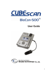
The system may be supplied with
a multifunctional remote hand
controller (See Figure 1). The
hand controller has five user
assignable function keys (S1 to
S5). All of the other functions of
the hand controller are marked on
the hand controller itself.
The individual functions of the
hand controller are described in
chapters S2 and S3 in this manual.
S1
S2
S3
SAVE
FREEZE
PRINT
PROBE
DIRECTION
DELETE
_
+
SAMPLE
_
+
The system is also supplied
“Infrared remote control ready”.
The optional infrared remote
control looks and works in the
same manner as the plug-in type.
The individual functions are the
same.
Note: The infrared remote control
should be pointed toward the IR
receiver window (at the top center
of the front of the Companion III
system or next to the Pioneer label
on the TC8080 system), in order
for it to work effectively.
MUTE
WINDOW
MENU
ESCAPE
ENTER
+
_
+
SWEEP
_
+
GAIN
+
_
DEPTH
S5
ZERO
AMPLITUDE
_
Infrared Remote
Control
_
S4
+
SCALE
Figure 1: The remote control.
Note: Please refer to the Safety Summary (Chapter H1) concerning
precautions using the infrared remote.
Note: With normal use, the batteries for the infrared remote should last
for about one year. When the remote no longer operates the system, or
operating range reduces, replace both batteries with new IEC LR03 AAA
Alkaline Manganese batteries. To replace the batteries, remove the four
screws at the back of the remote, remove the batteries from the holder
and replace with new batteries. Be sure to fit the batteries the correct way
around. Refit the rear cover and tighten the four screws.
• Don’t leave flat batteries in the remote control.
• Always replace both batteries at the same time.
• In the case of battery leakage, clean the battery holder and replace the
old batteries with new.
• Dispose of batteries carefully, in accordance with local regulations.
• Remove batteries if equipment is not likely to be used for a long time.
H2-3
Pioneer TC8080 and Companion III User Manual
Footswitch
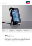
The system may be supplied with
an optional three function
footswitch (See Figure 1). The
footswitch has three user assignable switches (F1 to F3).
The configurability and functionality of the footswitch is described
in chapter S2 in this manual.
Figure 1: The footswitch.
Keyboard
The system is supplied with a
standard keyboard (See Figure 2)
for use in entering alpha-numeric
data.
The functionality of the keyboard
is described in chapter S2 in this
manual.
Note: A smaller version keyboard
containing a trackball pointing
device is also available as an
option.
H2-4
Figure 2: The keyboard.
Common Hardware Components
Pointing Devices
The system may be supplied with
an optional two button mouse
(See Figure 1).
The system may also be supplied
with an optional keyboard
containing a trackball pointing
device (See Figure 2).
A third type of pointing device
which is available is the
touchscreen display (See Figure
3).
Figure 1: The mouse.
The functionality of the three
pointing devices is described in
chapter S2 in this manual.
Note: The touchscreen display is
only available on the Companion
III system. Pioneer TC8080
systems and Companion III LE
models do not support the
touchscreen.
Figure 2: The trackball.
Figure 3: The touchscreen display.
H2-5
Pioneer TC8080 and Companion III User Manual
Available Transducers
The following optional transducers are supported by the systems:
•
•
•
•
•
•
•
1.6 MHz PW Monitoring
2 MHz PW Monitoring
2 MHz PW Handheld
4 MHz PW/CW Extracranial
8 MHz PW/CW Extracranial
16 MHz PW Microvascular
20 MHz PW Microvascular
Figure 1: Transcranial Monitoring Transducer 1.6 or 2 MHz PW.
Figure 2: Transcranial Handheld Transducer 2 MHz PW.
These are shown in the Figures on
this page.
Note: Only the 2 MHz transducers are available with two different sizes of crystals (10mm and
15mm). The part descriptions
contain the crystal width. Please
keep in mind that the crystal width
is not the same as the probe
housing diameter. The probe
housing diameter will always be
greater.
Note: The microvascular transducers are available with two
different diameters (1.5 and 2
mm). In this case, the diameter
refers to the probe housing
diameter and not the crystal size.
Figure 3: Extracranial Transducer 4 MHz PW/CW.
Figure 4: Extracranial Transducer 8 MHz PW/CW.
Figure 5: Microvascular Transducer 16 or 20 MHz PW.
Note: The transcranial monitoring transducers have a removable handle
which can be used to simulate a standard diagnostic handheld transducer.
Note: Certain transducers are also available with a longer 4.8 m cable
instead of the standard 2.5 m cable. Refer to the Optional Accessories list
later in this chapter for availability.
H2-6
Common Hardware Components
Analog Connection
Box
The system may be supplied with
an optional analog connection box
to simplify the use of the eight
analog inputs and eight analog
outputs (See Figure 1).
For convenience, the connection
of external devices should be
made via the Analog Connection
Box which contains eight standard
RCA input connectors and eight
standard RCA output connectors.
Refer to Chapter H3 or H4 for a
description of the proper connection procedure for the analog
connection box.
The Pioneer TC8080 and Companion III systems support the
ability to record and playback the
audio Doppler data using an
external DAT recorder. The
configurability and functionality
of the external inputs and outputs
is described in chapter S17 in this
manual.
Figure 1: Analog Connection Box.
H2-7
Pioneer TC8080 and Companion III User Manual
Printers
Various types of printers are
supported by the system. Essentially all printers which are
supported by the Windows
operating system can be used.
In the case that a color inkjet
printer is used, it is recommended
that the printer have both a color
ink cartridge as well as a black ink
cartridge.
Headphones
Standard audio headphones are
supported by the system.
Consumables
The only available consumable
for the system is a 250 ml bottle
of ultrasonic coupling gel.
Note: Only accessories or
consumables that are supplied or
recommended by Nicolet EME or
Nicolet Vascular should be used
with the system.
H2-8
Standard Pioneer
Accessories
Standard Companion
Accessories
The Pioneer TC8080 system is
delivered as follows:
The Companion III system is
delivered as follows:
• Main unit with CD-RW, 3.5
inch floppy drive, four Doppler
sockets, and stereo speakers.
• External Monitor with cables.
• Keyboard.
• Mouse.
• 2m Power (mains) lead.
• Microsoft Windows XP pack
plus driver and installation
disks and CDs.
• Adhesive Probe Holder.
• User Manual.
• NicVue Patient Administration
Software CD and Manual.
• Bottle of Gel.
• Main unit with CD-RW, 3.5
inch floppy drive, two Doppler
sockets, stereo speakers, and
probe holder.
• Internal Touchscreen Monitor.
• Keyboard.
• Mouse.
• 2m Power (mains) lead.
• Microsoft Windows XP pack
plus driver and installation
disks and CDs.
• User Manual.
• NicVue Patient Administration
Software CD and Manual.
• Bottle of Gel.
Note: Please ensure that the disks
and CDs are kept with the system.
A charge will be made for
replacements.
Note: Please ensure that the disks
and CDs are kept with the system.
A charge will be made for
replacements.
Note: The Companion III LE
model does not support the
touchscreen display. This system
just has an internal LCD display.
Common Hardware Components
Optional Accessories
The following is a list of the optional components available for the systems:
•
•
•
•
•
•
•
•
•
•
•
•
•
•
•
•
•
•
•
•
•
•
•
•
•
•
•
•
•
•
•
•
•
•
•
•
•
•
1.6 MHz PW 15mm monitoring transducer (probe) 2.5m
2 MHz PW diagnostic handheld (probe) 2.5m
2 MHz PW 15mm standard monitoring transducer (probe) 2.5m
2 MHz PW 10mm monitoring transducer (probe) 2.5m
4 MHz PW/CW active transducer (probe) 2.5m yellow
8 MHz PW/CW active transducer (probe) 2.5m green
1.5mm 16 MHz PW microvascular probe (Autoclaveable)
2.0mm 16 MHz PW microvascular probe (Autoclaveable)
1.5mm 20 MHz PW microvascular probe (Autoclaveable)
2.0mm 20 MHz PW microvascular probe (Autoclaveable)
16 MHz PW microvascular isolation pod
20 MHz PW microvascular isolation pod
1.6 MHz PW 15mm monitoring transducer (probe) 4.8m
2 MHz PW 10mm standard monitoring transducer (probe) 4.8m
2 MHz PW 15mm standard monitoring transducer (probe) 4.8m
Probe Carry Case
Probe Holder (Adhesive backed)
Infra-Red Remote Control (English)
Wired Remote Control (English)
Infra-Red Remote Control (German)
Wired Remote Control (German)
IR Remote Pod
Footswitch (3-way) for use with IR remotes
Footswitch (3-way) for use with wired remotes inc. RS232 PC card
Cherry Mini Keyboard
Keyboard including trackball
Microsoft Intellimouse Mouse
Analog Connection Box (8 Inputs / 8 Outputs)
Analog Connection Kit (8 Inputs / 8 Outputs)
Analog Connection Kit (8 Inputs / 8 Outputs)
Knurr Pioneer Cart inc. Drawer
Knurr Cart Rear Cover
TFT Monitor
17” Color Monitor
Hewlett Packard Color Printer inc Leads
Stereo Headphones
Service Manual Pioneer
Service Manual Companion
X1-P100
X1-P101
X1-P102
X1-P103
X1-P104
X1-P105
X1-P110
X1-P111
X1-P112
X1-P113
X1-P114
X1-P115
X1-P120
X1-P117
X1-P116
X2-P004
Pioneer only
M2-P001
M2-P002
M2-P003
M2-P004
M2-0516
X2-P001 Pioneer & all Companion
X2-P002 Pioneer only
M2-0491
M2-0445
340/SA/02
340/SA/19 Pioneer only
340/SA/04 Companion only
X9-0126
M1-P001
Pioneer only
MN-0012 Pioneer only
RC-0029
M2-0495
M7-P002
-
H2-9
Pioneer TC8080 and Companion III User Manual
Optional Accessories
(continued)
•
•
•
•
•
•
•
•
Reader Station Software
Dual Headband for 15mm Probe
Single Headband for 15mm Probe
Dual Headband for 10mm Probe
Single Headband for 10mm Probe
Single 15mm Probe Holder Attachment
Single 10mm Probe Holder Attachment
Pack of 10 Headband Cushion Pads and 5 Velcro Top Straps
H2-10
X9-0127 Pioneer & Companion
X2-P006
X2-P007
X2-P012
X2-P008
X2-P009
X2-P010
M2-0496
Companion III System
Chapter H3
Companion III System
Labels and Symbols
H3-3
Rear View of Companion III
H3-4
Front Quarter View of Companion III
H3-5
Connecting Accessories
Connecting the Keyboard
Connecting the Pointing Device
Connecting an External Printer
Connecting the Optional Footswitch
Connecting the Remote Hand Controller
Connecting a Set of Headphones
Connecting USB Peripherals
Connecting the Companion III to a Network
Connecting an External VGA Monitor
Connecting Serial Devices
Connecting Optional Analog Connection Box
Connecting an External DAT Recorder
Connecting the Standard Transducers to the System
Connecting the Microvascular Probes to the System
H3-6
H3-6
H3-6
H3-6
H3-6
H3-6
H3-7
H3-7
H3-7
H3-7
H3-7
H3-7
H3-7
H3-8
H3-9
Assembling the System
H3-10
Mains Power Supply
H3-11
Apply Power to the Companion III System
H3-11
This chapter provides information
concerning the assembly and set
up of the Companion III system.
Information in this chapter is
subject to change without notice.
H3-1
Pioneer TC8080 and Companion III User Manual
Blank Page
H3-2
Companion III System
Labels and Symbols
Mouse (Pointing Device) Connection
Line Out (3.5mm jack socket)
The following labels and symbols
are affixed to the Companion III:
Warns the user to consult this
manual and any other accompanying documentation
Line In (3.5mm jack socket)
Keyboard Connection
Microphone In (3.5mm jack
socket)
Power (Mains) Supply OFF
RJ-45 Network Connection
O
Power (Mains) Supply ON
I
USB (Universal Serial Bus)
Connection
Stereo Headphones (3.5mm jack
socket)
Parallel Printer Connection
Potential Equalization Terminal
Remote Controller Connector
H3-3
Pioneer TC8080 and Companion III User Manual
Figure 1: Rear View of the Companion III.
Pointing Device Socket
(Mouse/Track-Ball)
RS232 Serial Interface Socket
Power (Mains) Input Socket
Remote Control Socket
Power (Mains) On/Off Switch
Analog Outputs Socket
Power (Mains) Fuse Drawer
Analog Inputs Socket
Equipotential Terminal
VGA Monitor Signal Socket
Transducer (Probe) Holder
RJ-45 Network Socket
Cooling Fan Vent
USB (Universal Serial Bus)
Sockets
Carrying Handle
Keyboard Socket
Headphone Socket
Microphone Socket
Line Out Socket
Line In Socket
25Way Parallel Printer Socket
H3-4
Companion III System
Figure 2: Front Quarter View of the Companion III.
Infra-Red Remote Control Window
Resistive VGA Touch Screen
Loudspeaker (Two On System)
CD-RW Drive
1.44MB 3½” Floppy Disk Drive
Transducer (Probe) Socket
Transducer (Probe) Socket
H3-5
Pioneer TC8080 and Companion III User Manual
Connecting
Accessories
Connecting the
Keyboard
Connecting the
Optional Footswitch
To guarantee the highest level of
safety, only accessories that have
approval to EN 60601-1, and are
CE marked in accordance with the
Medical Devices Directive 93/42/
EEC should be connected to the
Companion III.
The keyboard should be connected to the 6-way miniature
DIN socket on the rear panel of
the Companion III (socket 2).
Connection of the Companion III
to any mains powered electrical
accessories must be in accordance
with IEC 601-1-1 : 2000. This
standard describes the safety
requirements for medical electrical systems to provide protection
to the patient, the operator and the
surroundings.
Connecting the
Pointing Device
An optional footswitch may be
connected to the Companion III.
Connect the footswitch to the RS232 Serial Interface Socket
(socket 8). Ensure that the cable is
fully screened and the connector
jackscrews are fully tightened.
This will ensure reliability and
EMC compliance.
For safety reasons accessories
must not be connected to the same
mains socket (e.g. via a multi
socket adapter) as the Companion III.
Connection to mains powered
electrical accessories that are not
approved to EN 60601-1 will
require additional protective
earthing. An isolation transformer
may also be required.
IEC 601-1-1 provides examples
for various combinations of
medical electrical equipment and
non-medical electrical equipment.
When accessory devices have
been connected, another safety
check of the device combination
will be necessary.
H3-6
The pointing device (mouse or
track-ball) should be connected to
the 6-way miniature DIN socket
on the rear panel of the Companion III (socket 1).
Connecting an
External Printer
The printer interface connector is
a Centronics SPP 25-way standard
D type socket fitted to the rear
panel (connector 7). Connection
to the external printer is via a 25
way parallel cable. Ensure that the
cable is fully screened and the
connector jackscrews are fully
tightened. This will ensure
reliability and EMC compliance.
Connecting the
Remote Hand
Controller
Connect the Remote Hand
Controller to the RS-232 Serial
connector (socket 8) on the back
panel. Ensure that the cable is
fully screened and the connector
jackscrews are fully tightened.
This will ensure reliability and
EMC compliance.
Please note that use of the remote
hand controller and the footswitch
precludes the use of other serial
accessories.
Companion III System
Connecting a set of
Headphones
Connecting an
External VGA Monitor
Use stereo headphones with a
3.5mm, 3-pole (stereo) Jack plug.
The connector (socket 3) is on the
rear of the Companion III. The
internal speakers will be automatically disconnected. The audio
signals can now be heard via the
headphones.
An extra external VGA monitor
may be connected to the Companion III. Connect the monitor
signal cable to the VGA Monitor
Signal Socket (socket 12). Ensure
that the cable is fully screened and
the connector jackscrews are fully
tightened. This will ensure
reliability and EMC compliance.
Connecting USB
Peripherals
Two USB compatible peripherals
may be connected to the USB
ports (sockets 14) on the back
panel.
Connecting the
Companion III to a
Network
It is possible to connect the
Companion III to a network.
Connect an RJ-45 compatible
patch cable to the RJ-45 socket
(socket 13) on the back panel.
Consult a network administrator
for setting up the networking
protocols in the operating system.
Connecting the
Optional Analog
Connection Box
An optional analog connection
box may be connected to the
Companion III. Connect the
analog connection box (2 cables)
to the Analog Inputs / Outputs
Sockets (sockets 10, 11). Ensure
that the cables are fully screened
and the connector jackscrews are
fully tightened. This will ensure
reliability and EMC compliance.
Connecting Serial
Devices
Standard serial port compatible
devices may be connected to the
9-way ‘D type’ RS 232 connector
(socket 8) on the back panel of the
Companion III. Ensure that the
cable is fully screened and the
connector jackscrews are fully
tightened. This will ensure
reliability and EMC compliance.
Please note that use of the remote
hand controller and footswitch
precludes the use of other serial
accessories.
Connecting an
External DAT
Recorder
If an external DAT recorder is to
be used to record and playback
the Doppler audio data via the
analog connection box, it needs to
be properly connected. Two
channels of audio information for
each Doppler FFT display are
required and these need to be
connected in the correct order for
the accurate reproduction of the
Doppler FFT flow direction from
the stored audio signals. Make
sure that the left and right DAT
channels are connected consistently for both the inputs and the
outputs. e.g. Left to connector 1
and right to connector 2 for both
the inputs and the outputs.
H3-7
Pioneer TC8080 and Companion III User Manual
Connecting the
Standard Transducers
to the System
!
System model may
vary from that which
is shown.
CAUTION
Make sure you align the red dots
in step 1 to guard against damage
to the transducer and/or system
connectors.
1. Align the Red dots on both the
system (sockets 27 and 28) and
the transducer connectors
(Figure 1).
Red dot
Red dot
2. Push the transducer connector
straight in all of the way.
Disconnecting a transducer
from the Companion III
system
Figure 1: Align the red dots and push the transducer straight into the
connector on the system.
Use this procedure to disconnect a
transducer from the system.
!
CAUTION
Do not pull on the transducer's
cable or damage to the transducer
and/or system may occur.
1. Grasp the knurled sleeve of
the transducer's connector
(Figure 2).
2. Carefully pull the transducer
connector straight out from the
system connector.
Figure 2: Grasp the knurled sleeve and pull straight out to remove the
transducer.
Your system's layout and components may differ from the examples
shown above and in the remainder of this guide.
H3-8
Companion III System
Connecting the
Microvascular Probes
to the System
The microvascular probes have
been designed to be as small as
possible, thereby allowing access
to microvessels in very restricted
areas. Because of the invasive
nature of microvascular applications, the probes are sterilizable.
Consequently, the microvascular
probe and the preamplifier (pod)
have been separated.
!
CAUTION
Never autoclave the microvascular pod (preamplifier) or immerse
the pod in a liquid.
Red dot
Red dot
Gray
Brown for 20 MHz Preamplifier
20 MHz Preamplifier
20 MHz Probe
Figure 1: Two channel Companion III main unit showing the 20 MHz
microvascular pod and the 20 MHz probe connected to Channel 1.
1. Connect the microvascular
preamplifier to the system as
shown in Figure 1 using the
same procedure as the standard
transducers on the previous
page.
Figure 2: Connecting the microvascular probe to the preamplifier.
2. Connect the microvascular
probe to the preamplifier as
shown in Figure 2 by simply
pressing the probe connector
onto the preamplifier.
Note: The Strain Relief is WHITE on the 16 MHz preamp and BROWN
on the 20 MHz preamp.
H3-9
Pioneer TC8080 and Companion III User Manual
Assembling the
System
Refer to the Front and Back Panel
diagrams and legend for socket,
connector and other locations.
1. Carefully unpack all of the
system components and make
sure none are missing or
damaged (refer to the shipping
list supplied with the system).
6. If the unit is to be connected to
a network, plug an RJ-45
compatible patch cable into the
RJ-45 socket (socket 13) on the
back panel.
7. If any USB peripherals are to
be used with this unit, connect
them to the USB Sockets (14)
on the back panel.
2. Ensure that the Power (Mains)
Switch (16) is in the O Off
position before continuing the
set-up procedure.
8. Connect the remote hand
controller to the Remote Hand
Controller Socket (9) on the
back panel. Ensure that the
cable is fully screened and the
connector jackscrews are fully
tightened. This will ensure
reliability and EMC compliance.
3. If a printer is to be used, plug
the 25-way Centronics printer
cable from the printer to the
25-Way Parallel Printer Socket
(7) on the back panel. Ensure
that the cable is fully screened
and the connector jackscrews
are fully tightened. This will
ensure reliability and EMC
compliance.
9. If the optional footswitch is to
be used with this unit, connect
the footswitch to the RS-232
Serial Interface Socket (socket
8). Ensure that the cable is
fully screened and the connector jackscrews are fully
tightened. This will ensure
reliability and EMC compliance.
4. Connect the keyboard plug to
the Keyboard Socket (2) on the
back panel.
10. If a second VGA monitor is to
be used with this unit, connect
the monitor signal cable to the
VGA Monitor Signal Socket
(socket 12). Ensure that the
cable is fully screened and the
connector jackscrews are fully
tightened. This will ensure
reliability and EMC compliance.
5. Connect the pointing device
(mouse or track-ball) to the
Pointing Device Socket (1) on
the back panel.
H3-10
11. If the optional analog connection box is to be used with this
unit, connect the analog
connection box (2 cables) to
the Analog Inputs / Outputs
Sockets (sockets 10, 11).
Ensure that the cables are fully
screened and the connector
jackscrews are fully tightened.
This will ensure reliability and
EMC compliance. In addition,
make sure that the external
device (e.g. DAT recorder) is
also properly connected.
12. Plug the Power (Mains) Lead
into the Power (Mains) Inlet
(1) on the rear of the unit, and
into a suitable wall socket.
13. The unit is now ready to be
switched on.
Companion III System
Mains Power Supply
The Companion III can automatically detect and set itself for
voltages between110V and 240V.
Before connecting the Companion III to a mains electrical
supply, check that the Power
(Mains) Switch is set to off then
connect any peripherals and
accessories required.
Apply power to the
Companion III system
After assembling the system and
connecting the Companion III to
the power (mains) supply, it may
be switched on. The Power
(Mains) Switch (16) is on the rear
of the Companion III next to the
power input socket.
When the unit is off, the switch
should be at position “O”. To
switch on the Companion III,
ensure that a mains cable is
connected to the system and a
power socket, and push the switch
to position “I”.
Figure 1: System power switch.
Note: The unit will perform some self-tests before ‘booting’ into
Windows; the time this takes may vary depending on other software or
peripherals added to the Companion III. The Windows screen will be
displayed when the unit is ready. Please note that the exact number and
type of icons shown on the screen may differ depending on the software
or hardware installed.
H3-11
Pioneer TC8080 and Companion III User Manual
Blank Page
H3-12
Pioneer TC8080 System
Chapter H4
Pioneer TC8080 System
Labels and Symbols
H4-3
Back Panel of the Pioneer TC8080
H4-4
Front Panel of the Pioneer TC8080
H4-5
Connecting Accessories
Connecting the Keyboard
Connecting the Pointing Device
Connecting an External Printer
Connecting the Optional Footswitch
Connecting the Remote Hand Controller
Connecting a Set of Headphones
Connecting USB Peripherals
Connecting the Companion III to a Network
Connecting an External VGA Monitor
Connecting Serial Devices
Connecting Optional Analog Connection Box
Connecting an External DAT Recorder
Connecting the Standard Transducers to the System
Connecting the Microvascular Probes to the System
H4-6
H4-6
H4-6
H4-6
H4-6
H4-6
H4-7
H4-7
H4-7
H4-7
H4-7
H4-7
H4-7
H4-8
H4-9
Assembling the System
H4-10
Mains Power Supply
H4-12
Apply Power to the Pioneer TC8080 System
H4-12
This chapter provides information
concerning the assembly and set
up of the Pioneer TC8080 system.
Information in this chapter is
subject to change without notice.
H4-1
Pioneer TC8080 and Companion III User Manual
Blank Page
H4-2
Pioneer TC8080 System
Labels and Symbols
Mouse (Pointing Device) Connection
RS-232 Serial Connnection
The following labels and symbols
are affixed to the Pioneer
TC8080:
Line Out (3.5mm jack socket)
Warns the user to consult this
manual and any other accompanying documentation
Keyboard Connection
Line In (3.5mm jack socket)
RJ-45 Network Connection
Power (Mains) Supply OFF
O
Microphone In (3.5mm jack
socket)
Power (Mains) Supply ON
USB (Universal Serial Bus)
Connection
I
Stereo Headphones (3.5mm jack
socket)
Parallel Printer Connection
Potential Equalization Terminal
VGA Monitor Signal Connection
H4-3
Pioneer TC8080 and Companion III User Manual
Figure 1: Back Panel of the Pioneer TC8080.
Power (Mains) Inlet
Pointing Device Socket
Fuse Drawer and Input
Voltage Selector
Keyboard Socket
Line (Audio) Out Socket
(connect to 17 only)
Microphone In Socket
RJ-45 Network Socket
Isolated Power (Mains) Outlets
Potential Equalization Terminal
2 USB Sockets
Line (Audio) In Socket
(connect to 15 only)
25-Way Parallel Printer Socket
Line (Audio) Out Socket
VGA Monitor Signal Socket
Analog Inputs Socket
RS-232 Serial Port Socket
Analog Outputs Socket
Line In Socket
Cooling Fan Exhaust Vents
Thermal Circuit Breaker
Isolated Power Output Voltage
Selector Switch
H4-4
Pioneer TC8080 System
Figure 2: Front Panel of the Pioneer TC8080.
Stereo Headphone Socket
Hard Disk Activity Indicator
IrDA Window
Loudspeakers
Transducer (Probe) Sockets
Spare 5¼” Drive Bays
CD Writer / Rewriter
3½” Floppy Disk Drive
Power (Mains) Switch
H4-5
Pioneer TC8080 and Companion III User Manual
Connecting
Accessories
Connecting the
Keyboard
Connecting the
Optional Footswitch
To guarantee the highest level of
safety, only accessories that have
approval to EN 60601-1, and are
CE marked in accordance with the
Medical Devices Directive 93/42/
EEC should be connected to the
Pioneer TC8080.
The keyboard should be connected to the 6-way miniature
DIN socket on the rear panel of
the Pioneer TC8080 (socket 8).
Connection of the Pioneer
TC8080 to any mains powered
electrical accessories must be in
accordance with IEC 601-1-1 :
2000. This standard describes the
safety requirements for medical
electrical systems to provide
protection to the patient, the
operator and the surroundings.
Connecting the
Pointing Device
An optional footswitch may be
connected to the Pioneer
TC8080. Connect the footswitch
to the RS-232 Serial Interface
Socket (socket 13). Ensure that
the cable is fully screened and the
connector jackscrews are fully
tightened. This will ensure
reliability and EMC compliance.
Please note that use of the
footswitch precludes the use of
other serial accessories.
For safety reasons accessories
must not be connected to the same
mains socket (e.g. via a multi
socket adapter) as the Pioneer
TC8080.
Connection to mains powered
electrical accessories that are not
approved to EN 60601-1 will
require additional protective
earthing. An isolation transformer
may also be required.
IEC 601-1-1 provides examples
for various combinations of
medical electrical equipment and
non-medical electrical equipment.
When accessory devices have
been connected, another safety
check of the device combination
will be necessary.
H4-6
The pointing device (mouse or
track-ball) should be connected to
the 6-way miniature DIN socket
on the rear panel of the Pioneer
TC8080 (socket 7).
Connecting an
External Printer
The printer interface connector is
a Centronics SPP 25-way standard
D type socket fitted to the rear
panel (connector 11). Connection
to the external printer is via a 25
way parallel cable. Ensure that the
cable is fully screened and the
connector jackscrews are fully
tightened. This will ensure
reliability and EMC compliance.
The printer should be powered
from one of the power outlets (3)
on the TC8080.
Connecting the
Remote Hand
Controller
Connect the Remote Hand
Controller to the RS-232 Serial
connector (socket 13) on the back
panel. Ensure that the cable is
fully screened and the connector
jackscrews are fully tightened.
This will ensure reliability and
EMC compliance.
Please note that use of the remote
hand controller precludes the use
of other serial accessories.
Pioneer TC8080 System
Connecting a set of
Headphones
Connecting an
External VGA Monitor
Use stereo headphones with a
3.5mm, 3-pole (stereo) Jack plug.
The connector (socket 22) is on
the rear of the Pioneer TC8080.
The internal speakers will be
automatically disconnected. The
audio signals can now be heard
via the headphones.
An extra external VGA monitor
may be connected to the Pioneer
TC8080. Connect the monitor
signal cable to the VGA Monitor
Signal Socket (socket 12). Ensure
that the cable is fully screened and
the connector jackscrews are fully
tightened. This will ensure
reliability and EMC compliance.
Connecting USB
Peripherals
Two USB compatible peripherals
may be connected to the USB
ports (sockets 10) on the back
panel.
Connecting the
Pioneer TC8080 to a
Network
It is possible to connect the
Pioneer TC8080 to a network.
Connect an RJ-45 compatible
patch cable to the RJ-45 socket
(socket 9) on the back panel.
Consult a network administrator
for setting up the networking
protocols in the operating system.
Connecting the
Optional Analog
Connection Box
An optional analog connection
box may be connected to the
Pioneer TC8080. Connect the
analog connection box (2 cables)
to the Analog Inputs / Outputs
Sockets (sockets 19, 20). Ensure
that the cables are fully screened
and the connector jackscrews are
fully tightened. This will ensure
reliability and EMC compliance.
Connecting Serial
Devices
Standard serial port compatible
devices may be connected to the
9-way ‘D type’ RS 232 connector
(socket 13) on the back panel of
the Pioneer TC8080. Ensure that
the cable is fully screened and the
connector jackscrews are fully
tightened. This will ensure
reliability and EMC compliance.
Please note that use of the remote
hand controller or footswitch
precludes the use of other serial
accessories.
Connecting an
External DAT
Recorder
If an external DAT recorder is to
be used to record and playback
the Doppler audio data via the
analog connection box, it needs to
be properly connected. Two
channels of audio information for
each Doppler FFT display are
required and these need to be
connected in the correct order for
the accurate reproduction of the
Doppler FFT flow direction from
the stored audio signals. Make
sure that the left and right DAT
channels are connected consistently for both the inputs and the
outputs. e.g. Left to connector 1
and right to connector 2 for both
the inputs and the outputs.
H4-7
Pioneer TC8080 and Companion III User Manual
Connecting the
Standard Transducers
to the System
Red dot
!
System model may
vary from that which
is shown.
CAUTION
Make sure you align the red dots
in step 1 to guard against damage
to the transducer and/or system
connectors.
Red dot
1. Align the Red dots on both the
system (sockets 26) and the
transducer connectors (Figure
1).
2. Push the transducer connector
straight in all of the way.
Figure 1: Align the red dots and push the transducer straight into the
connector on the system.
Disconnecting a transducer
from the Pioneer TC8080
system
Use this procedure to disconnect a
transducer from the system.
!
CAUTION
Do not pull on the transducer's
cable or damage to the transducer
and/or system may occur.
1. Grasp the knurled sleeve of
the transducer's connector
(Figure 2).
2. Carefully pull the transducer
connector straight out from the
system connector.
Figure 2: Grasp the knurled sleeve and pull straight out to remove the
transducer.
Your system's layout and components may differ from the examples
shown above and in the remainder of this guide.
H4-8
Pioneer TC8080 System
Connecting the
Microvascular Probes
to the System
The microvascular probes have
been designed to be as small as
possible, thereby allowing access
to microvessels in very restricted
areas. Because of the invasive
nature of microvascular applications, the probes are sterilizable.
Consequently, the microvascular
probe and the preamplifier (pod)
have been separated.
!
CAUTION
Never autoclave the microvascular pod (preamplifier) or immerse
the pod in a liquid.
Red dot
Red dot
Gray
Brown for 20 MHz Preamplifier
20 MHz Preamplifier
20 MHz Probe
Figure 1: Four channel Pioneer TC8080 main unit showing the 20
MHz microvascular pod and the 20 MHz probe connected to Channel
4.
1. Connect the microvascular
preamplifier to the system as
shown in Figure 1 using the
same procedure as the standard
transducers on the previous
page.
Figure 2: Connecting the microvascular probe to the preamplifier.
2. Connect the microvascular
probe to the preamplifier as
shown in Figure 2 by simply
pressing the probe connector
onto the preamplifier.
Note: The Strain Relief is WHITE on the 16 MHz preamp and BROWN
on the 20 MHz preamp.
H4-9
Pioneer TC8080 and Companion III User Manual
Assembling the
System
Refer to the Front and Back Panel
diagrams and legend for socket,
connector and other locations.
1. Carefully unpack all of the
system components and make
sure none are missing or
damaged (refer to the shipping
list supplied with the system).
2. Place the components on the
cart using Figure 1 on the next
page for guidance.
3. Ensure that the Power (Mains)
Switch (30) is in the “O” Off
position before continuing the
set-up procedure.
4. Set the Power Voltage Selector
Switches (2) and (6) to the
required voltage for the
country in which the TC 8080
is to be used.
5. Plug the monitor power lead
from the monitor power inlet to
a Power Outlet (3) on the back
panel. Plug the monitor signal
lead into the VGA Monitor
Signal socket (12) on the back
panel. Ensure that the cable is
fully screened and the connector jackscrews are fully
tightened. This will ensure
reliability and EMC compliance.
H4-10
6. Plug the printer power lead
from the printer power inlet to
a Power Outlet (3) on the back
panel. Plug the 25-way
Centronics printer cable from
the printer to the 25-Way
Parallel Printer Socket (11) on
the back panel. Ensure that the
cable is fully screened and the
connector jackscrews are fully
tightened. This will ensure
reliability and EMC compliance.
7. Connect the keyboard plug to
the Keyboard Socket (8) on the
back panel.
8. Connect the pointing device
(mouse or track-ball) to the
Pointing Device Socket (7) on
the back panel.
9. If the unit is to be connected to
a network, plug an RJ-45
compatible patch cable into the
RJ-45 socket (socket 9) on the
back panel.
10. If any USB peripherals are to
be used with this unit, connect
them to the USB Sockets (10)
on the back panel.
11. Connect the remote hand
controller to the Remote Hand
Controller Socket (13) on the
back panel. Ensure that the
cable is fully screened and the
connector jackscrews are fully
tightened. This will ensure
reliability and EMC compliance.
12. If the optional footswitch is to
be used with this unit, connect
the footswitch to the RS-232
Serial Interface Socket (socket
13). Ensure that the cable is
fully screened and the connector jackscrews are fully
tightened. This will ensure
reliability and EMC compliance.
13. Connect the audio bypass lead
to the Line Out Socket (15),
and to the Line In Socket (17).
14. If the optional analog connection box is to be used with this
unit, connect the analog
connection box (2 cables) to
the Analog Inputs / Outputs
Sockets (sockets 19, 20).
Ensure that the cables are fully
screened and the connector
jackscrews are fully tightened.
This will ensure reliability and
EMC compliance. In addition,
make sure that the external
device (e.g. DAT recorder) is
also properly connected.
15. Plug the Power (Mains) Lead
into the Power (Mains) Inlet
(1) on the rear of the unit, and
into a suitable wall socket.
16. The unit is now ready to be
switched on.
Pioneer TC8080 System
Figure 1: Pioneer TC8080 system on a cart.
Note: Depending on the country of distribution, the cart model may vary.
H4-11
Pioneer TC8080 and Companion III User Manual
Mains Power Supply
The Pioneer TC 8080 can be setup to run on either 100-120V, or
200-240V AC electrical supplies.
Before connecting the Pioneer
TC 8080 to a mains electrical
supply, check that the Power
(Mains) Selector Switches are set
to the correct voltage. Do not
change the switch setting whilst
the unit is switched on.
Set to 115V for 100 - 120V
Set to 230V for 200 - 240V
Apply power to the
Pioneer TC8080
system
After assembling the system and
connecting the Pioneer TC8080
to the power (mains) supply, it
may be switched on. The Power
(Mains) Switch (30) is on the
front of the Pioneer TC8080 next
to the TC8080 label.
When the unit is off, the switch
should be at position “O”. To
switch on the Pioneer TC8080,
ensure that a mains cable is
connected to the system and a
power socket, and push the switch
to position “I”.
H4-12
Figure 1: System power switches.
Note: When the unit has been ‘shut-down’ in Windows, the power to
the motherboard, HDD, CD-RW, FDD, and any PCI and USB peripherals is automatically disconnected. The Transducer Probe Sockets (26),
the internal audio amplifier, and the Power (Mains) Outlets are still live
until the Power (Mains) Switch is set to position “O” Off.
Note: The unit will perform some self-tests before ‘booting’ into
Windows; the time this takes may vary depending on other software or
peripherals added to the Pioneer TC8080. The Windows screen will be
displayed when the unit is ready. Please note that the exact number and
type of icons shown on the screen may differ depending on the software
or hardware installed.
Care and Maintenance of the Equipment
Chapter H5
Care and Maintenance
of the Equipment
Cleaning the Equipment
Keyboard
Mouse
SVGA Monitor
Printer
Pioneer TC8080 Base Unit
Companion III Systen Box
Touch Screen Monitor
Cart System
H5-3
H5-3
H5-3
H5-3
H5-3
H5-3
H5-4
H5-4
H5-4
Care of Transducers
H5-4
Cleaning Standard Transducers
H5-4
Cleaning the Microvascular Transducers
H5-4
Cleaning the Microvascular Pods
H5-4
Sterilizing 16 MHz and 20 MHz Probes
H5-5
Durability of Probes
H5-5
User Maintenance Companion III
If the Companion III system does not power up
If the pointing device (mouse/trackball) does not work
If the keyboard does not work
If the printer does not work
If there is no sound from the loudspeakers
H5-6
H5-6
H5-6
H5-6
H5-6
H5-6
User Maintenance Pioneer TC8080
If the Pioneer TC8080 system does not power up
If the monitor is blank with yellow Power Saving LED On
If the color on the screen is not uniform
If the picture is fuzzy
If the mouse does not work
If the keyboard does not work
H5-6
H5-6
H5-7
H5-7
H5-7
H5-7
H5-7
Servicing the Instrument
H5-8
This chapter provides information
concerning the care and maintenance of the Pioneer TC8080 and
Companion III systems.
Information in this chapter is
subject to change without notice.
H5-1
Pioneer TC8080 and Companion III User Manual
Blank Page
H5-2
Care and Maintenance of the Equipment
Cleaning the
Equipment
!
Printer
• The ball and underside of the
mouse should be regularly
cleaned using a soft, lint free
cloth and mild detergent.
• Use a soft cloth moistened with
water to wipe dust, smudges
and stains off the exterior case.
WARNING
Disconnect from ‘mains’ supply
before cleaning the unit.
!
Mouse
CAUTION
Care should be taken to allow NO
liquid ingress into the unit, the
keyboard/trackball, the SVGA
monitor or printer.
Keyboard
• The keyboard case and keys
may be cleaned using a damp,
soft, lint free cloth.
• Do not use any petroleum
based solvents such as ethanol,
as this may damage the plastic
components used in the
keyboard construction.
• Do not pour or spray cleaning
solutions directly onto the
keyboard, as this could result
in electrical failure of the
keyboard.
• Do not use any petroleum
based solvents such as ethanol,
as this may damage the
components used in the
construction.
• To remove the ball, turn the
ball collar anti-clockwise.
• The ball can now be removed
by inverting the mouse to
allow the ball to fall into the
palm of the hand.
• Blow gently into the mouse
housing, or wipe out with a
soft cloth to remove any dust,
or lint that might have collected. If the mouse remains
‘sluggish’, try using a cotton
swab to clean the bearings and
rubber rollers.
• Do not use any type of abrasive
pad, scouring powder or
solvent.
Pioneer TC8080 Base Unit
• Using a soft lint free cloth
lightly moistened with a mild
detergent solution, gently wipe
the exterior surfaces of the base
unit. Take great care to allow
no liquid ingress into any of
the connectors on the rear
panel, or the disk drive, CDRW, connectors and power
switch on the front panel.
• Using a soft brush, remove any
dust from the fan grilles
located on the rear panel.
• Refitting is the reverse of
removal.
SVGA Monitor
• Clean the cabinet, panel and
controls with a soft cloth
moistened with a mild detergent solution.
• Do not use any type of abrasive
pad, scouring powder or
solvent.
H5-3
Pioneer TC8080 and Companion III User Manual
Companion III System Box
• Using a soft lint free cloth
lightly moistened with a mild
detergent solution, gently wipe
the exterior surfaces of the base
unit excluding the touch screen
monitor. Take great care to
allow no liquid ingress into any
of the connectors or power
socket/switch on the rear panel,
or the disk drive, CD-RW and
connectors on the side panel.
• Using a soft brush, remove any
dust from the fan grilles
located on the rear panel.
Care of Transducers
Transducers are particularly
sensitive. Please observe the
following points:
• Do not drop or knock against a
hard surface.
• Regularly clean off remains of
contact gel.
• Do not immerse in fluids.
• Do not pull on the transducer
cable.
!
Touch Screen Monitor
• Wipe the screen lightly with a
soft lint-free cloth. If necessary, a small amount of
detergent may be used.
• Do not use any type of abrasive
pad, scouring powder or
solvent.
Cart System
• Using a soft lint free cloth
moistened with a mild detergent solution, wipe all of the
surfaces to remove any dust,
smudges or stains.
CAUTION
Rough handling of the transducers
(probes) can cause severe damage
to the ceramic crystals.
Cleaning Standard
Transducers
The 1.6 MHz, 2 MHz, 4 MHz,
and 8 MHz probes should be
cleaned using the following
procedure:
1. Clean the Doppler Transducers
(Probes) using a soft, lint free
cloth moistened with a mild
cleaning agent. Do not use
solvents or alcohol! Do not
immerse the probes or sensors.
!
CAUTION
Do not heat or autoclave any of
the standard transducers.
H5-4
Cleaning the
Microvascular
Transducers
The 16 MHz and 20 MHz probes
should be cleaned using the
following procedure:
1. Clean the Microvascular
Transducers (Probes) using a
soft, lint free cloth moistened
with a mild cleaning agent.
Isopropyl-alcohol and /or a
mild disinfectant solution may
also be used to clean these
transducers.
Cleaning the
Microvascular Pods
The Microvascular pods should be
cleaned using the following
procedure:
1. The pre-amplifier pod must
not be sterilized as this could
damage internal components
and leave the pod unsafe for
further use. Clean the pod and
cable with a moist cloth
dampened with isopropylalcohol or a disinfectant
solution.
!
CAUTION
Do not immerse the pod in liquid
as this could damage internal
components.
Care and Maintenance of the Equipment
The 16 MHz and 20 MHz probes
can be sterilized using one of the
following two procedures in the
next column:
1. Autoclave at 134º Celsius
(273º Fahrenheit) for 3
minutes. For the cool down
procedure, see the time table
pertaining to the specific
autoclave unit being used.
Remove the transducer from
the autoclave and cool to room
temperature.
Note: Where ever appropriate,
follow the sterile practice guidelines of your institution and the
instructions from the manufacturer of the sterilizing unit.
However, NEVER exceed the
temperature listed in the following procedures.
2. Autoclave at 121º Celsius
(250º Fahrenheit) for 15
minutes. For the cool down
procedure, see the time table
pertaining to the specific
autoclave unit being used.
Remove the transducer from
the autoclave and cool to room
temperature.
Sterilizing 16 MHz
and 20 MHz Probes
!
CAUTION
Always separate the EME
microvascular pod (preamplifier)
from the probe before sterilizing
the probe. Never autoclave the
microvascular pod (preamplifier)
or immerse the pod in a liquid.
!
CAUTION
Refer to the documentation and
instructions that accompany the
microvascular pod and transducers for additional cleaning and
sterilising information.
Durability of Probes
The sterilization procedures
recommended will not affect the
performance of the probes.
However the frequent washing
and handling will increase the
likelihood of damage. Consequently the recommendation is a
maximum of 20 washing/sterilization cycles after which the probe
must be replaced.
!
WARNING
Any transducer that shows signs
of damage should be replaced
immediately. DO NOT USE
transducers with cracked or
exposed parts or bare wires.
Patient safety will be compromised.
!
CAUTION
Use only Nicolet approved /
supplied electrodes and transducers. See your Nicolet distributor or
call in the USA. Use of nonapproved electrodes or transducers might adversely affect the
function of your system.
!
WARNING
The preceding instructions are
subject to change without
notice. Always follow the
specific procedures that accompanied the parts (e.g., microvascular probes); your institution's
guidelines for cleaning, disinfecting and sterilizing parts;
and the instructions from the
manufacturer of the sterilizing
unit. However the probe
sterilization temperature must
NEVER exceed the values listed
on this page or damage to the
probe may result.
H5-5
Pioneer TC8080 and Companion III User Manual
User Maintenance
Companion III
In case of a fault, User Maintenance is limited to the following:
If the Companion III system
does not ‘power-up’
• Check that the ‘mains’ power
supply lead is connected to the
Power (Mains) Inlet (15), is
connected to a suitable ‘mains’
outlet, and is switched on.
• Check the Power (Mains)
Switch (16), is in the ‘on’
position.
If the pointing device (mouse/
trackball) does not work:
• Ensure that the mouse connector is connected to the Pointing
Device Socket (1).
• Clean the mouse, inside and
out as described earlier in this
chapter.
If the keyboard does not
work:
• Ensure that the keyboard
connector is connected to the
Keyboard Socket (2) on the
rear panel.
If the printer does not work:
• Check the Power (Mains) Input
fuses in the Fuse Drawer (17).
Input ‘mains’ fuses are
accessed by pulling out the
fuse drawer located beside the
Power (Mains) Switch (16).
Ensure that the Power (Mains)
Lead is disconnected and the
unit is switched of before
accessing the fuses. Replacement fuses are as follows:
Two off T2.5AH 250V 20mm
fuses to ‘IEC 127’ should be
fitted.
• Check the ‘mains’ fuse in the
‘mains’ plug (if fitted).
• Ensure that the printer connector is connected to the 25-Way
Parallel Printer Socket (7) on
the rear panel, and to the
Centronics connector on the
printer.
• Check that there is enough ink
in the cartridges contained in
the printer and a paper supply
in the printer’s hopper.
If there is no sound from the
loudspeakers:
• Select ‘Start/Settings/Control
Panel’ then open ‘Sounds and
Multimedia’. Ensure that the
Sound Volume option in the
Sounds tab is not set hard over
to the left.
H5-6
• Double-click the loudspeaker
icon just left of the clock in the
taskbar. Ensure that none of the
sliders have a tick mark in the
‘Mute’ box.
User Maintenance
Pioneer TC8080
In case of a fault, User Maintenance is limited to the following:
If the Pioneer TC8080 system
does not ‘power-up’
• Check that the Voltage
Selector Switches (2) and (6)
are set to the correct voltage
for the country in which the
system is being used.
• Check that the ‘mains’ power
supply lead is connected to the
Power (Mains) Inlet (1), is
connected to a suitable ‘mains’
outlet, and is switched on.
• Check the Power (Mains)
Switch (30), on the front panel,
is in the ‘on’ position.
• Check that the voltage selector
inside the Fuse Drawer (2) is
installed the right way round.
On 100-120V systems the
‘115’ side should be visible; on
200-240V systems the ‘230’
side should be visible.
Care and Maintenance of the Equipment
• Check the Power (Mains) Input
fuses in the Fuse Drawer (2).
Input ‘mains’ fuses are
accessed by disconnecting the
‘mains’ power supply lead and
pulling out the fuse drawer
located below the Power
(Mains) Inlet (1). Replacement
fuses are as follows:
Two off T5AH 250V 20mm
fuses to ‘IEC 127’ should be
fitted.
• Check the ‘mains’ fuse in the
‘mains’ plug (if fitted).
If the unit ‘powers-up’, but
the SVGA monitor is blank:
• Check that the monitor power
lead is connected between the
monitor and the IEC outlet on
the rear of the unit.
• Check the power switch on the
monitor is in the ‘on’ position.
breaker has 'tripped', the inner
black button will be approximately 6mm proud of the
plastic bezel. Check the state of
the thermal circuit breaker if
the monitor and/or printer fail
to power up.
• Should the circuit breaker trip,
switch off the Pioneer TC8080
system and disconnect from the
mains supply. The monitor and
printer must be checked for
electrical safety and operation
by an authorized and qualified
service engineer before further
use. Following the safety
checks and fault rectification,
depress the inner button on the
circuit breaker, reconnect all
items and power up.
If the monitor is blank with
yellow ‘Power Saving’ LED
On:
• Check the Thermal Circuit
Breaker on the rear panel has
not ‘tripped’.
• Check that the monitor signal
lead (15-way density and a half
‘D’ connector) is connected to
the VGA Monitor Signal
Socket on the rear of the unit.
• Isolated ‘mains’ outputs for the
external monitor and printer
are protected by a 2A Thermal
Circuit Breaker (5). This is
located on the rear panel below
the Isolated Power Outlets (3).
If the color on the screen is
not uniform:
• In normal operation the inner
black button should be approximately 3mm proud of the
plastic bezel. If a fault has
occurred with the isolated
power output and the circuit
switched on and can be
manually initiated from the
‘Menu/Option’ on screen
display on the monitor.
If the picture is fuzzy:
• Adjust the brightness, contrast
and convergence controls.
• A degauss cycle is initiated
whenever the monitor is
switched on and can be
manually initiated from the
‘Menu/Option’ on screen
display on the monitor.
If the mouse does not work:
• Ensure that the mouse connector is connected to the Pointing
Device Socket (8).
• Clean the mouse, inside and
out as described earlier in this
chapter.
If the keyboard does not
work:
• Ensure that the keyboard
connector is connected to the
Keyboard Socket (7) on the
rear panel.
• If the monitor is close to any
potential sources of magnetic
fields, color may not be
uniform. Try to move the
monitor away from the source.
• A degauss cycle is initiated
whenever the monitor is
H5-7
Pioneer TC8080 and Companion III User Manual
Servicing the
Instrument
If User Maintenance is unable to
solve a fault in the instrument then
Servicing will be required.
Service must be exclusively
carried out by the authorised
distributor:
Nicolet Vascular Inc.
A Subsidiary of VIASYS
Healthcare
5225 Verona Road
Building 2
Madison, WI 53711
USA
US Toll Free:
1 800 525 2519
US Toll: 1 608 441 2266
US FAX:
1 608 441 2232
Or the manufacturer:
SciMed Ltd.
Unit 5, Avon Business Park
Lodge Causeway
Fishponds
Bristol BS16 3JP
United Kingdom
Tel:
Fax:
+44 (0)117 958 3754
+44 (0)117 958 4089
or persons explicitly authorized
by the above.
If unauthorized persons attempt
service, then all responsibility
passes to the customer and all
warranties become void.
H5-8
Technical Specification
Chapter H6
Technical Specification
PC Specifications
H6-3
Doppler Specifications
H6-3
Inputs / Outputs Specifications
H6-5
Analog / Audio I/O Specifications
H6-6
System Feature Specifications
H6-6
Regulatory Compliance Specifications
H6-6
Environmental Requirements Specifications
H6-7
Measurements and Weights Specifications
H6-7
Mains Supply Specifications
H6-7
Fuse Rating Specifications
H6-7
Acoustic Output Specifications
Measurement Uncertainties
1.6 MHz 15mm PW Output Table
2 MHz 10mm PW Output Table
2 MHz 15mm PW Output Table
4 MHz PW Output Table
4 MHz CW Output Table
8 MHz PW Output Table
8 MHz CW Output Table
16 MHz 1.5mm PW Output Table
16 MHz 2.0mm PW Output Table
20 MHz 1.5mm PW Output Table
20 MHz 2.0mm PW Output Table
Acoustic Output in IEC 1157 Format
H6-8
H6-8
H6-9
H6-10
H6-11
H6-12
H6-13
H6-14
H6-15
H6-16
H6-17
H6-18
H6-19
H6-20
Accuracy of Values Specifications
Vertical Scale Accuracy
Horizontal Scale Accuracy
Accuracy of Values Tables
H6-23
H6-23
H6-24
H6-25
This chapter provides technical
specifications for both the Pioneer
TC8080 and Companion III
systems.
Information in this chapter is
subject to change without notice.
H6-1
Pioneer TC8080 and Companion III User Manual
Blank Page
H6-2
Technical Specification
PC Specifications
Companion III System
Pioneer TC8080 System
• Industrial Style AXIOM SBC
8361 VEA or improved variant
motherboard.
• Intel Desktop Board D815EEA
(or equivalent). Incorporating:
• Intel Pentium III 850 MHz
Processor (minimum).
• 256 MB DIMM RAM (minimum).
• 80 GB fixed hard disk storage
(minimum).
• On board Intel 82815 AGP
video controller.
• On board Soundmax integrated
digital audio.
• Intel Pentium III 1 GHz
Processor (minimum).
• 512 MB DIMM RAM.
• 1.44 MB HD floppy disk
storage.
• 120 GB fixed hard disk storage
(minimum).
• Internal DVD-RW Drive.
• On board Graphics Adapter.
• 1.44 MB HD floppy disk
storage.
• 6 Wire Resistive touch screen.
• Internal DVD-RW Drive.
• Medical grade ATX 200W
PSU.
Doppler
Specifications
• 1.6MHz, 2MHz, 4MHz and
8MHz transducer (probe)
frequencies.
• 1.6MHz, 2MHz, 4MHz and
8MHz transducer (probe)
frequencies.
• 16MHz and 20MHz Microvascular transducer (probe)
frequencies available via
isolation pod.
• 16MHz and 20MHz Microvascular transducer (probe)
frequencies available via
isolation pod.
• 64, 128, or 256 point FFT.
• 64, 128, or 256 point FFT.
• High-resolution FFT frequency
spectrum analysis with up to
64 levels of color display.
• High-resolution FFT frequency
spectrum analysis with up to
64 levels of color display.
H6-3
Pioneer TC8080 and Companion III User Manual
Doppler
Specifications
(Continued)
H6-4
Companion III System
Pioneer TC8080 System
• Real time maximum frequency
envelope.
• Real time maximum frequency
envelope.
• Frequency response:
to 32 kHz.
• Frequency response:
to 32 kHz.
75 Hz
75 Hz
• Wall Filter:
75 Hz to 600 Hz (switchable).
• Wall Filter:
75 Hz to 600 Hz (switchable).
• Selectable sweep rates 1 sec to
41 sec, depending on the
number of channels displayed.
• Selectable sweep rates 1 sec to
41 sec, depending on the
number of channels displayed.
• Acoustic reproduction of the
Doppler signals via two
broadband loudspeakers or
optional stereo headphones,
flow separated or non-directional.
• Acoustic reproduction of the
Doppler signals via two
broadband loudspeakers or
optional stereo headphones,
flow separated or non-directional.
• Noise reduction toggle for high
sound quality.
• Noise reduction toggle for high
sound quality.
• Squelch/gel mute control.
• Squelch/gel mute control.
• Boost control, 2 or 3 levels.
• Boost control, 2 or 3 levels.
• Up to 8 depths on any channel.
• Up to 8 depths on any channel.
• Up to 2 transducers (probes)
running simultaneously.
• Up to 4 transducers (probes)
running simultaneously.
• Fixed single frequency
operation at any one time.
• Choice of any 2 frequencies
running simultaneously.
Technical Specification
Inputs / Outputs
Specifications
Companion III System
Pioneer TC8080 System
• 2 Self detecting active Doppler
transducer (probe) sockets.
• 4 Self detecting active Doppler
transducer (probe) sockets.
• Infrared remote hand controller
sensor.
• Infrared remote hand controller
sensor.
• 6-way mini DIN mouse/
pointing device socket.
• 6-way mini DIN mouse/
pointing device socket.
• 6-way mini DIN keyboard
socket.
• 6-way mini DIN keyboard
socket.
• Microphone socket.
• Microphone socket.
• Line in socket.
• Line in socket.
• Line out socket.
• Line out socket.
• Stereo headphone socket.
• Stereo headphone socket.
• 2 USB sockets
• 2 USB sockets
• RJ-45 network connector.
• RJ-45 network connector.
• 25-way parallel printer
connector.
• 25-way parallel printer
connector.
• SVGA monitor connector.
• SVGA monitor connector.
• Analogue/Audio (8 channels
in/out) 15-way D-plug and
socket.
• Analogue/Audio (8 channels
in/out) 15-way D-plug and
socket.
• 2 RS 232 serial port connectors.
• RS 232 serial port connector.
• Joystick / MIDI socket.
H6-5
Pioneer TC8080 and Companion III User Manual
Analog / Audio I/O
Specifications
(Available as an optional accessory)
System Feature
Specifications
Regulatory
Compliance
Specifications
H6-6
Companion III System
Pioneer TC8080 System
• Analog/Audio Inputs (8
channels - Curves or 4 pairs
Phase/Quad). Voltage up to
10Vpp with adjustable gain.
Input impedance 100 kOhm.
PRF sample rate compatible
with all Companion and
Pioneer systems (Maximum
31.7 kHz).
• Analog/Audio Inputs (8
channels - Curves or 4 pairs
Phase/Quad). Voltage up to
10Vpp with adjustable gain.
Input impedance 100 kOhm.
PRF sample rate compatible
with all Companion and
Pioneer systems (Maximum
31.7 kHz).
• Analog/Audio Outputs (8
channels - Curves or 4 pairs
Phase/Quad). Voltage up to
10Vpp. Output impedance 100
Ohm.
• Analog/Audio Outputs (8
channels - Curves or 4 pairs
Phase/Quad). Voltage up to
10Vpp. Output impedance 100
Ohm.
• Remote hand controller wired
or infrared.
• Remote hand controller wired
or infrared.
• Windows 2000 or Windows
XP operating system environment.
• Windows 2000 or Windows
XP operating system environment.
• Interface to Nic Vue patient
database.
• Interface to Nic Vue patient
database.
• Support for all Windows
compatible printers.
• Support for all Windows
compatible printers.
• 12.1 inch 800 x 600 TFT
screen with touch screen
technology.
• CRT / TFT LCD color monitor
with up to 1280 x 1024
resolution.
• IBM PS/2 style QWERTY
keyboard with integral pointing
device.
• IBM PS/2 style QWERTY
keyboard with integral pointing
device.
• See Chapter H1.
• See Chapter H1.
Technical Specification
Environmental
Requirements
Specifications
Measurements and
Weights
Specifications
Mains Supply
Specifications
Companion III System
Pioneer TC8080 System
• Storage temperature:
-20ºC to +60ºC.
• Storage temperature:
-20ºC to +60ºC.
• Storage humidity:
8% to 80% (relative, noncondensing).
• Storage humidity:
8% to 80% (relative, noncondensing).
• Storage atmospheric pressure:
500 hPa to 1060 hPa.
• Storage atmospheric pressure:
500 hPa to 1060 hPa.
• Operating temperature:
10ºC to 40ºC.
• Operating temperature:
10ºC to 40ºC.
• Operating humidity:
15% to 80% (relative, noncondensing).
• Operating humidity:
15% to 80% (relative, noncondensing).
• Operating atmospheric
pressure: 700 hPa to 1060 hPa.
• Operating atmospheric
pressure: 700 hPa to 1060 hPa.
• 325 mm x 405 mm x 290 mm
(height x width x depth).
• 180 mm x 495 mm x 455 mm
(height x width x depth).
• Weight: 9 kg (approximately).
• Weight: 15kg (approximately).
• 100 V to 240 V AC 50/60 Hz,
150 VA.
• 100 V to 120 V AC 50/60 Hz
and
200 V to 240 V AC 50/60 Hz
350 VA switchable.
• Integrated 150 VA isolation
transformer powering 2
integrated power outlets.
Fuse Rating
Specifications
• 2 x T2.5AH 250V 20mm to
IEC Sheet III.
• 2 x T5.0AH 250V 20mm to
IEC Sheet III.
H6-7
Pioneer TC8080 and Companion III User Manual
Acoustic Output
Specifications
The following pages provide
information on the ultrasound
intensity output of the Pioneer
TC8080 and Companion III
systems. The data for each
transducer is presented in an
individual table. Refer to Figure 1
on this page for a list of the
symbols used and their definitions.
Measurement
Uncertainties
MI = Mechanical Index
TISSCAN = Soft tissue Thermal Index in auto-scanning mode
TISNON-SCAN = Soft tissue Thermal Index in non auto-scanning mode
TIB = Bone Thermal Index
TIC = Cranial Thermal Index
Aaprt = Area of active aperture (cm2)
Pr.3 = Derated peak rarefactional pressure
Wo = Ultrasonic Power, except for TISSCAN in which case it is the ultrasonic
power passing through a 1 cm2 window (mw)
W3(z1) = Derated ultrasonic power at axial distance z1
ITA.3(z1) = Derated spatial-peak, temporal-average intensity at axial distance
z1 (mW/cm2)
z1 = Axial distance corresponding to location of max
[min(W.3(z),ITA.3(z)x1cm2)] where z > zbp (cm)
zbp = 1.69(Aaprt)0.5
For MI zsp is the axial distance at which Pr.3 is measured; for TIB, zsp is
axial distance at which TIB is a maximum (i.e. zsp = zb.3) (cm)
The associated measurement
uncertainties are as follows:
Power = +29%, -37%
Intensity = +18%, -22%
Pressure = +9%, -12%
Center Frequency = +1.5%, -1.5%
deq(z)
= Equivalent beam diameter as a function of axial distance z, and
is equal to [(4/Π)(Wo/ITA(z))]0.5 where ITA(z) is the temporal-average
intensity as a function of z (cm)
fc = Center frequency (MHz)
PD = Pulse Duration (µs)
PRF = Pulse Repetition Frequency
pr@PIImax = Peak rarefactional pressure where free-field spatial peal pulse
intensity integral is a maximum (megapascals)
ISPPA.3 = Derated spatial peak, pulse average intensity (W/cm2)
FL= Focal Length, or aximuthal and elevational lengths if different (cm)
ROC = Radius Of Curvature (cm)
deq@PIImax = Equivalent beam diameter where free-field spatial-peak pulse
intensity integral is maximum (cm)
Figure 1: Symbols Used and Their Definitions.
H6-8
Technical Specification
Pioneer TC8080 and Companion III Acoustic Output Reporting Table for Track 3
Transducer Model: 1.6 MHz 15mm diameter
Operating Mode: Pulsed Doppler (PW)
TIS
Index Label
TIB
non-scan
MI
scan
<1
Global Maximum Index Value
Assoc
Acoustic
Parameter
non-scan
Aaprt <=1
Aaprt >1
na
na
na
-
-
Pr.3
(mPa)
Wo
(mW)
min of [W.3(Z1),ITA.3(Z1)]
(mW)
-
Z1
(cm)
-
Zbp
(cm)
-
Zsp
(cm)
deq(Zsp)
(cm)
fc
(MHz)
TIC
na
2.3
-
136
#
#
-
#
-
-
-
-
1.6
X (cm)
-
-
-
-
1.5
Y (cm)
-
-
-
-
1.5
Dim of Aaprt
PD
(usec)
#
PRF
(Hz)
#
pr @ PIImax
(Mpa)
#
deq @ PIImax
(cm)
Other
Information
-
FLx
(cm)
-
-
-
unfocused
FLy
(cm)
-
-
-
unfocused
Focal Length
IpA.3 @ MImax
#
Amplitude
Operating
Control
Conditions
100%
PRF
5.3 kHz
Sample Width
12
(data provided where global maximum displayed index exceeds 1.0)
# indicates that no data is reported because the associated index value < 1
H6-9
Pioneer TC8080 and Companion III User Manual
Pioneer TC8080 and Companion III Acoustic Output Reporting Table for Track 3
Transducer Model: 2 MHz 10mm diameter
Operating Mode: Pulsed Doppler (PW)
TIS
Index Label
TIB
non-scan
MI
scan
<1
Global Maximum Index Value
Assoc
Acoustic
Parameter
non-scan
Aaprt <=1
Aaprt >1
na
na
na
-
-
Pr.3
(mPa)
Wo
(mW)
min of [W.3(Z1),ITA.3(Z1)]
(mW)
-
Z1
(cm)
-
Zbp
(cm)
-
Zsp
(cm)
deq(Zsp)
(cm)
fc
(MHz)
TIC
na
1.3
-
52
#
#
-
#
-
-
-
-
2.0
X (cm)
-
-
-
-
1.0
Y (cm)
-
-
-
-
1.0
Dim of Aaprt
PD
(usec)
#
PRF
(Hz)
#
pr @ PIImax
(Mpa)
#
deq @ PIImax
(cm)
Other
Information
-
FLx
(cm)
-
-
-
unfocused
FLy
(cm)
-
-
-
unfocused
Focal Length
IpA.3 @ MImax
#
Amplitude
Operating
Control
Conditions
100%
PRF
5.3 kHz
Sample Width
(data provided where global maximum displayed index exceeds 1.0)
# indicates that no data is reported because the associated index value < 1
H6-10
12
Technical Specification
Pioneer TC8080 and Companion III Acoustic Output Reporting Table for Track 3
Transducer Model: 2 MHz 15mm diameter
Operating Mode: Pulsed Doppler (PW)
TIS
Index Label
TIB
non-scan
MI
scan
<1
Global Maximum Index Value
Assoc
Acoustic
Parameter
non-scan
Aaprt <=1
Aaprt >1
na
na
na
-
-
Pr.3
(mPa)
Wo
(mW)
min of [W.3(Z1),ITA.3(Z1)]
(mW)
-
Z1
(cm)
-
Zbp
(cm)
-
Zsp
(cm)
deq(Zsp)
(cm)
fc
(MHz)
TIC
na
1.9
-
115
#
#
-
#
-
-
-
-
2.0
X (cm)
-
-
-
-
1.5
Y (cm)
-
-
-
-
1.5
Dim of Aaprt
PD
(usec)
#
PRF
(Hz)
#
pr @ PIImax
(Mpa)
#
deq @ PIImax
(cm)
Other
Information
-
FLx
(cm)
-
-
-
unfocused
FLy
(cm)
-
-
-
unfocused
Focal Length
IpA.3 @ MImax
#
Amplitude
Operating
Control
Conditions
100%
PRF
7.9 kHz
Sample Width
8
(data provided where global maximum displayed index exceeds 1.0)
# indicates that no data is reported because the associated index value < 1
H6-11
Pioneer TC8080 and Companion III User Manual
Pioneer TC8080 and Companion III Acoustic Output Reporting Table for Track 3
Transducer Model: 4 MHz
Operating Mode: Pulsed Doppler (PW)
TIS
Index Label
TIB
non-scan
MI
scan
<1
Global Maximum Index Value
Assoc
Acoustic
Parameter
non-scan
Aaprt <=1
Aaprt >1
na
<1
na
-
#
Pr.3
(mPa)
Wo
(mW)
min of [W.3(Z1),ITA.3(Z1)]
(mW)
-
Z1
(cm)
-
Zbp
(cm)
-
Zsp
(cm)
deq(Zsp)
(cm)
fc
(MHz)
TIC
na
na
-
-
#
#
-
#
-
#
-
-
-
X (cm)
-
#
-
-
-
Y (cm)
-
#
-
-
-
Dim of Aaprt
PD
(usec)
#
PRF
(Hz)
#
pr @ PIImax
(Mpa)
#
deq @ PIImax
(cm)
Other
Information
-
FLx
(cm)
-
#
-
-
FLy
(cm)
-
#
-
-
Focal Length
IpA.3 @ MImax
#
Amplitude
Operating
Control
Conditions
PRF
Sample Width
(data provided where global maximum displayed index exceeds 1.0)
# indicates that no data is reported because the associated index value < 1
H6-12
Technical Specification
Pioneer TC8080 and Companion III Acoustic Output Reporting Table for Track 3
Transducer Model: 4 MHz
Operating Mode: Continuous Doppler (CW)
TIS
Index Label
TIB
non-scan
MI
scan
<1
Global Maximum Index Value
Assoc
Acoustic
Parameter
non-scan
Aaprt <=1
Aaprt >1
na
<1
na
-
#
Pr.3
(mPa)
Wo
(mW)
min of [W.3(Z1),ITA.3(Z1)]
(mW)
-
Z1
(cm)
-
Zbp
(cm)
-
Zsp
(cm)
deq(Zsp)
(cm)
fc
(MHz)
TIC
na
na
-
-
#
#
-
#
-
#
-
-
-
X (cm)
-
#
-
-
-
Y (cm)
-
#
-
-
-
Dim of Aaprt
PD
(usec)
#
PRF
(Hz)
#
pr @ PIImax
(Mpa)
#
deq @ PIImax
(cm)
Other
Information
-
FLx
(cm)
-
#
-
-
FLy
(cm)
-
#
-
-
Focal Length
IpA.3 @ MImax
#
Amplitude
Operating
Control
Conditions
PRF
Sample Width
(data provided where global maximum displayed index exceeds 1.0)
# indicates that no data is reported because the associated index value < 1
H6-13
Pioneer TC8080 and Companion III User Manual
Pioneer TC8080 and Companion III Acoustic Output Reporting Table for Track 3
Transducer Model: 8 MHz
Operating Mode: Pulsed Doppler (PW)
TIS
Index Label
TIB
non-scan
MI
scan
<1
Global Maximum Index Value
Assoc
Acoustic
Parameter
non-scan
Aaprt <=1
Aaprt >1
na
<1
na
-
#
Pr.3
(mPa)
Wo
(mW)
min of [W.3(Z1),ITA.3(Z1)]
(mW)
-
Z1
(cm)
-
Zbp
(cm)
-
Zsp
(cm)
deq(Zsp)
(cm)
fc
(MHz)
TIC
na
na
-
-
#
#
-
#
-
#
-
-
-
X (cm)
-
#
-
-
-
Y (cm)
-
#
-
-
-
Dim of Aaprt
PD
(usec)
#
PRF
(Hz)
#
pr @ PIImax
(Mpa)
#
deq @ PIImax
(cm)
Other
Information
-
FLx
(cm)
-
#
-
-
FLy
(cm)
-
#
-
-
Focal Length
IpA.3 @ MImax
#
Amplitude
Operating
Control
Conditions
PRF
Sample Width
(data provided where global maximum displayed index exceeds 1.0)
# indicates that no data is reported because the associated index value < 1
H6-14
Technical Specification
Pioneer TC8080 and Companion III Acoustic Output Reporting Table for Track 3
Transducer Model: 8 MHz
Operating Mode: Continuous Doppler (CW)
TIS
Index Label
TIB
non-scan
MI
scan
<1
Global Maximum Index Value
Assoc
Acoustic
Parameter
non-scan
Aaprt <=1
Aaprt >1
na
1.33
na
-
34.91
Pr.3
(mPa)
Wo
(mW)
min of [W.3(Z1),ITA.3(Z1)]
(mW)
-
Z1
(cm)
-
Zbp
(cm)
-
Zsp
(cm)
deq(Zsp)
(cm)
fc
(MHz)
TIC
na
na
-
-
#
#
-
#
-
8
-
-
-
X (cm)
-
0.7
-
-
-
Y (cm)
-
0.35
-
-
-
Dim of Aaprt
PD
(usec)
#
PRF
(Hz)
#
pr @ PIImax
(Mpa)
#
deq @ PIImax
(cm)
Other
Information
-
FLx
(cm)
-
unfocused
-
-
FLy
(cm)
-
unfocused
-
-
Focal Length
IpA.3 @ MImax
Operating
Control
Conditions
#
Amplitude
100%
PRF
CW
Sample Width
CW
(data provided where global maximum displayed index exceeds 1.0)
# indicates that no data is reported because the associated index value < 1
H6-15
Pioneer TC8080 and Companion III User Manual
Pioneer TC8080 and Companion III Acoustic Output Reporting Table for Track 3
Transducer Model: 16 MHz 1.5mm diameter
Operating Mode: Pulsed Doppler (PW)
TIS
Index Label
TIB
non-scan
MI
scan
<1
Global Maximum Index Value
Assoc
Acoustic
Parameter
non-scan
Aaprt <=1
Aaprt >1
na
<1
na
-
#
Pr.3
(mPa)
Wo
(mW)
min of [W.3(Z1),ITA.3(Z1)]
(mW)
-
Z1
(cm)
-
Zbp
(cm)
-
Zsp
(cm)
deq(Zsp)
(cm)
fc
(MHz)
TIC
na
na
-
-
#
#
-
#
-
#
-
-
-
X (cm)
-
#
-
-
-
Y (cm)
-
#
-
-
-
Dim of Aaprt
PD
(usec)
#
PRF
(Hz)
#
pr @ PIImax
(Mpa)
#
deq @ PIImax
(cm)
Other
Information
-
FLx
(cm)
-
#
-
-
FLy
(cm)
-
#
-
-
Focal Length
IpA.3 @ MImax
#
Amplitude
Operating
Control
Conditions
PRF
Sample Width
(data provided where global maximum displayed index exceeds 1.0)
# indicates that no data is reported because the associated index value < 1
H6-16
Technical Specification
Pioneer TC8080 and Companion III Acoustic Output Reporting Table for Track 3
Transducer Model: 16 MHz 2.0mm diameter
Operating Mode: Pulsed Doppler (PW)
TIS
Index Label
TIB
non-scan
MI
scan
<1
Global Maximum Index Value
Assoc
Acoustic
Parameter
non-scan
Aaprt <=1
Aaprt >1
na
<1
na
-
#
Pr.3
(mPa)
Wo
(mW)
min of [W.3(Z1),ITA.3(Z1)]
(mW)
-
Z1
(cm)
-
Zbp
(cm)
-
Zsp
(cm)
deq(Zsp)
(cm)
fc
(MHz)
TIC
na
na
-
-
#
#
-
#
-
#
-
-
-
X (cm)
-
#
-
-
-
Y (cm)
-
#
-
-
-
Dim of Aaprt
PD
(usec)
#
PRF
(Hz)
#
pr @ PIImax
(Mpa)
#
deq @ PIImax
(cm)
Other
Information
-
FLx
(cm)
-
#
-
-
FLy
(cm)
-
#
-
-
Focal Length
IpA.3 @ MImax
#
Amplitude
Operating
Control
Conditions
PRF
Sample Width
(data provided where global maximum displayed index exceeds 1.0)
# indicates that no data is reported because the associated index value < 1
H6-17
Pioneer TC8080 and Companion III User Manual
Pioneer TC8080 and Companion III Acoustic Output Reporting Table for Track 3
Transducer Model: 20 MHz 1.5mm diameter
Operating Mode: Pulsed Doppler (PW)
TIS
Index Label
TIB
non-scan
MI
scan
<1
Global Maximum Index Value
Assoc
Acoustic
Parameter
non-scan
Aaprt <=1
Aaprt >1
na
<1
na
-
#
Pr.3
(mPa)
Wo
(mW)
min of [W.3(Z1),ITA.3(Z1)]
(mW)
-
Z1
(cm)
-
Zbp
(cm)
-
Zsp
(cm)
deq(Zsp)
(cm)
fc
(MHz)
TIC
na
na
-
-
#
#
-
#
-
#
-
-
-
X (cm)
-
#
-
-
-
Y (cm)
-
#
-
-
-
Dim of Aaprt
PD
(usec)
#
PRF
(Hz)
#
pr @ PIImax
(Mpa)
#
deq @ PIImax
(cm)
Other
Information
-
FLx
(cm)
-
#
-
-
FLy
(cm)
-
#
-
-
Focal Length
IpA.3 @ MImax
#
Amplitude
Operating
Control
Conditions
PRF
Sample Width
(data provided where global maximum displayed index exceeds 1.0)
# indicates that no data is reported because the associated index value < 1
H6-18
Technical Specification
Pioneer TC8080 and Companion III Acoustic Output Reporting Table for Track 3
Transducer Model: 20 MHz 2.0mm diameter
Operating Mode: Pulsed Doppler (PW)
TIS
Index Label
TIB
non-scan
MI
scan
<1
Global Maximum Index Value
Assoc
Acoustic
Parameter
non-scan
Aaprt <=1
Aaprt >1
na
<1
na
-
#
Pr.3
(mPa)
Wo
(mW)
min of [W.3(Z1),ITA.3(Z1)]
(mW)
-
Z1
(cm)
-
Zbp
(cm)
-
Zsp
(cm)
deq(Zsp)
(cm)
fc
(MHz)
TIC
na
na
-
-
#
#
-
#
-
#
-
-
-
X (cm)
-
#
-
-
-
Y (cm)
-
#
-
-
-
Dim of Aaprt
PD
(usec)
#
PRF
(Hz)
#
pr @ PIImax
(Mpa)
#
deq @ PIImax
(cm)
Other
Information
-
FLx
(cm)
-
#
-
-
FLy
(cm)
-
#
-
-
Focal Length
IpA.3 @ MImax
#
Amplitude
Operating
Control
Conditions
PRF
Sample Width
(data provided where global maximum displayed index exceeds 1.0)
# indicates that no data is reported because the associated index value < 1
H6-19
Pioneer TC8080 and Companion III User Manual
Acoustic Output in IEC 1157 format of Pioneer TC8080 and Companion III
a
b
c
RGD - Range Gated Depth
SVL - Sample Volume Length
S - Scale settings (PRF)
P - Power
Ø denotes diameter
Controllable by user
H6-20
Technical Specification
Acoustic Output in IEC 1157 format of Pioneer TC8080 and Companion III cont.
a
b
c
RGD - Range Gated Depth
SVL - Sample Volume Length
S - Scale settings (PRF)
P - Power
Ø denotes diameter
Controllable by user
H6-21
Pioneer TC8080 and Companion III User Manual
Acoustic Output in IEC 1157 format of Pioneer TC8080 and Companion III cont.
a
b
c
RGD - Range Gated Depth
SVL - Sample Volume Length
S - Scale settings (PRF)
P - Power
Ø denotes diameter
Controllable by user
H6-22
Technical Specification
Accuracy of Values
Specifications
The Doppler parameters calculated and displayed in the Pioneer
TC8080 and Companion III
systems are all based on the FFT
spectral display. The accuracy of
the vertical and horizontal scales
determine the accuracy of the
parameter measurements. The
following pages explain these
measurements and provide tables
containing their accuracies.
Accuracy of scale = +/- PRF / (2 * FFT Resolution)
Where: Accuracy of scale is expressed in cm/sec or kHz
PRF (full scale setting) is expressed in cm/sec or kHz
FFT resolution is expressed in number of points (64/128/256)
Examples
1. If the scale setting is -81 cm/sec -> +81 cm/sec and the FFT resolution
is 256 points, then the accuracy of scale velocity =
+/- 162 cm/sec / (2 * 256) = +/- 0.316 cm/sec
2. If the scale setting is -2.00 kHz -> +5.93 kHz and the FFT resolution
is 128 points, then the accuracy of scale frequency =
+/- 7.93 kHz / (2 * 128) = +/- 0.031 kHz
Vertical Scale
Accuracy
The accuracy of the vertical scale
of the FFT spectral display
depends on two adjustable factors
(the PRF and the FFT resolution)
and can be calculated using the
formula in Figure 1.
The best case accuracy on the
velocity measurements result from
using the lowest scale setting and
the highest FFT resolution. The
worst case accuracy on the
velocity measurements result from
using the highest scale setting and
the lowest FFT resolution.
Figure 1: Formula for calculating the vertical scale accuracy.
Note: It is important to remember that the accuracy of measurement
depends on the operator obtaining a good envelope curve for the signal
as described in this guide.
Note: As explained in this guide, all measurements of velocity assume
an insonation angle of zero degrees.
Note: The Gosling Pulsatility Index (PI) and the Pourcelot Resistance
Index (RI) are calculations dependent on the accuracy of the MEAN,
SYS, and DIA contained in the tables. Since these calculations are non
linear, it is impossible to state the actual accuracy of measurement for
the PI and RI. The accuracy of calculations depend on the nature of the
signal.
H6-23
Pioneer TC8080 and Companion III User Manual
Horizontal Scale
Accuracy
The accuracy of the spectral time
values (horizontal scale of the
FFT spectral display) is dependent
on one adjustable factor (the
sweep speed) and can be calculated using the formula in Figure
1.
The best case accuracy on the
spectral time resolution measurements result from using the fastest
sweep speed. The worst case
accuracy on the spectral time
resolution measurements result
from using the slowest sweep
speed.
H6-24
Accuracy of spectral time values = +/- Sweep speed / 512
Where: Accuracy of spectral time values is expressed in seconds
Sweep speed (full length spectrum) is expressed in seconds
Example
1. If the full spectral sweep speed is 4.1 seconds, then the accuracy of
spectral time values = +/- 4.1 seconds / 512 = 0.008 seconds
Figure 1: Formula for calculating the spectral time value accuracy.
Note: The accuracy of the Spectral Time Cursors are dependent on the
accuracy of the Spectral Time Resolution as expressed in the tables. The
Spectral Time Cursors will have the same accuracy of measurement as
the Spectral Time Resolution.
Technical Specification
1.6 MHz Operation
Mean Velocity (MEAN)
Mean Frequency (MEAN)
Peak Systolic Velocity (SYS)
Peak Systolic Frequency (SYS)
End Diastolic Velocity (DIA)
End Diastolic Frequency (DIA)
Spectral Time Resolution
Best Case Accuracy
Worst Case Accuracy
Unit of Measure
+/- 0.190
+/- 0.004
+/- 0.190
+/- 0.004
+/- 0.190
+/- 0.004
+/- 0.004
+/- 5.142
+/- 0.105
+/- 5.142
+/- 0.105
+/- 5.142
+/- 0.105
+/- 0.080
cm/sec
kHz
cm/sec
kHz
cm/sec
kHz
Seconds
Best Case Accuracy
Worst Case Accuracy
Unit of Measure
+/- 0.151
+/- 0.004
+/- 0.151
+/- 0.004
+/- 0.151
+/- 0.004
+/- 0.004
+/- 4.113
+/- 0.105
+/- 4.113
+/- 0.105
+/- 4.113
+/- 0.105
+/- 0.081
cm/sec
kHz
cm/sec
kHz
cm/sec
kHz
Seconds
Best Case Accuracy
Worst Case Accuracy
Unit of Measure
+/- 0.075
+/- 0.004
+/- 0.075
+/- 0.004
+/- 0.075
+/- 0.004
+/- 0.004
+/- 4.836
+/- 0.248
+/- 4.836
+/- 0.248
+/- 4.836
+/- 0.248
+/- 0.081
cm/sec
kHz
cm/sec
kHz
cm/sec
kHz
Seconds
2 MHz Operation
Mean Velocity (MEAN)
Mean Frequency (MEAN)
Peak Systolic Velocity (SYS)
Peak Systolic Frequency (SYS)
End Diastolic Velocity (DIA)
End Diastolic Frequency (DIA)
Spectral Time Resolution
4 MHz Operation
Mean Velocity (MEAN)
Mean Frequency (MEAN)
Peak Systolic Velocity (SYS)
Peak Systolic Frequency (SYS)
End Diastolic Velocity (DIA)
End Diastolic Frequency (DIA)
Spectral Time Resolution
H6-25
Pioneer TC8080 and Companion III User Manual
8 MHz Operation
Mean Velocity (MEAN)
Mean Frequency (MEAN)
Peak Systolic Velocity (SYS)
Peak Systolic Frequency (SYS)
End Diastolic Velocity (DIA)
End Diastolic Frequency (DIA)
Spectral Time Resolution
Best Case Accuracy
Worst Case Accuracy
Unit of Measure
+/- 0.038
+/- 0.004
+/- 0.038
+/- 0.004
+/- 0.038
+/- 0.004
+/- 0.004
+/- 2.418
+/- 0.248
+/- 2.418
+/- 0.248
+/- 2.418
+/- 0.248
+/- 0.081
cm/sec
kHz
cm/sec
kHz
cm/sec
kHz
Seconds
Best Case Accuracy
Worst Case Accuracy
Unit of Measure
+/- 0.019
+/- 0.004
+/- 0.019
+/- 0.004
+/- 0.019
+/- 0.004
+/- 0.004
+/- 1.209
+/- 0.248
+/- 1.209
+/- 0.248
+/- 1.209
+/- 0.248
+/- 0.081
cm/sec
kHz
cm/sec
kHz
cm/sec
kHz
Seconds
Best Case Accuracy
Worst Case Accuracy
Unit of Measure
+/- 0.015
+/- 0.004
+/- 0.015
+/- 0.004
+/- 0.015
+/- 0.004
+/- 0.004
+/- 0.967
+/- 0.248
+/- 0.967
+/- 0.248
+/- 0.967
+/- 0.248
+/- 0.081
cm/sec
kHz
cm/sec
kHz
cm/sec
kHz
Seconds
16 MHz Operation
Mean Velocity (MEAN)
Mean Frequency (MEAN)
Peak Systolic Velocity (SYS)
Peak Systolic Frequency (SYS)
End Diastolic Velocity (DIA)
End Diastolic Frequency (DIA)
Spectral Time Resolution
20 MHz Operation
Mean Velocity (MEAN)
Mean Frequency (MEAN)
Peak Systolic Velocity (SYS)
Peak Systolic Frequency (SYS)
End Diastolic Velocity (DIA)
End Diastolic Frequency (DIA)
Spectral Time Resolution
H6-26
Introduction
Chapter S1
Introduction to WinTCD
What is WinTCD?
S1-3
Performing Doppler Examinations
S1-3
This chapter provides a basic
introduction to the WinTCD
software package which is used
on both the Pioneer TC8080 and
Companion III systems.
!
WARNING
In all cases, the original data
must be reviewed if a clinical
decision is involved.
!
WARNING
WinTCD is not intended for
data acquisition on any nonmedical device (such as a
standard PC) that comes in
direct electrical contact with a
patient.
Information in this chapter is
subject to change without notice.
S1-1
Pioneer TC8080 and Companion III User Manual
Blank Page
S1-2
Introduction
What is WinTCD?
WinTCD is a TransCranial
Doppler ultrasound software
package, which runs on either the
Pioneer TC8080 system or the
Companion III system. The
following non-invasive methodologies are included:
• Diagnostic cerebrovascular
and extracranial investigation.
• Extended-term unilateral,
bilateral, and multilateral
cerebrovascular monitoring.
• Microvascular studies.
Additional features include:
• Handheld transducers (1.6
MHz, 2 MHz, 4 MHz, and 8
MHz) can be applied to
insonnate either intracranial or
extracranial blood vessels, so
that a record of vascular blood
flow velocity can be generated.
In routine diagnostic investigations, the transducers are
usually hand-held, enabling
signals of interest to be quickly
insonnated and optimized.
• A 2 MHz monitoring transducer can be mounted in a
headpiece and secured in
position once a good Doppler
signal is located.
• Up to two or four monitoring
transducers can be used
simultaneously depending on
the hardware system.
• Microvascular transducers are
also available:
16 MHz Microvascular PW
20 MHz Microvascular PW
• You can configure your system
to display either Spectra or
extended-term trend curves,
copy windows (or any combination thereof) and additional
information such as the mean
velocity, etc., may be obtained.
• Extended-term trend curves are
generated from the real-time
analog waves which enable
you to view data trends on a
single screen.
• The software allows spectra to
be labeled and saved to the
hard disk.
• Information stored during the
examination may be reviewed
via the Nicolet NicVue TCD
Review mode.
Performing Doppler
Examinations
The systems are designed for
trained and skilled personnel in
collecting transcranial data and
peripheral Doppler ultrasound
from a test subject. This manual is
intended to describe the controls
and functions of the system and
software only.
If information is needed on the
basic principles and examination
techniques, please refer to the vast
amount of literature available. The
standard work is:
Transcranial Doppler
Sonography, edited by Rune
Aaslid, published by Springer
Verlag, Wien / New York, 1986.
For more information on available
application training seminars,
please contact Nicolet or your
local Nicolet distributor.
• SoundTrak recordings which
allows the system to record
both audio Doppler data and
spectral data.
See your Nicolet NicVue
User Guide that shipped
with your system for instructions on using the NicVue
program.
S1-3
Pioneer TC8080 and Companion III User Manual
Blank Page
S1-4
Entering Commands
Chapter S2
Entering Commands
Mouse commands
Moving the mouse pointer
Selecting an option with the mouse
S2-3
S2-3
S2-3
Using the touchscreen display
S2-4
Keyboard commands
Underlined letter commands
Pull down menu selections
S2-5
S2-5
S2-6
Entering text using the keyboard
Text edit command keys
S2-7
S2-7
Entering text using the mouse and keyboard
S2-7
Using the remote control
S2-8
Using the footswitch
S2-9
Resizing a window
S2-10
Moving a window
S2-10
Maximizing a window
S2-10
This chapter describes the various
methods of entering commands to
your system:
• Mouse / Trackball
• Touchscreen Display
• Keyboard
• Remote Control
• Footswitch
It will be very beneficial to read
through this chapter and become
familiar with the various methods.
You then can choose which
method best meets your personal
preference and continue with the
next chapter.
Note: Although there are three
methods for entering commands,
not all three can be used for
certain operations. For example,
alphanumeric entries must by
typed in via the keyboard and
certain softkey commands can
only be entered via the keyboard
or remote control.
S2-1
Pioneer TC8080 and Companion III User Manual
Blank Page
S2-2
Entering Commands
Mouse commands
Your system can be controlled
using a mouse. There are,
however, some functions which
can only be accessed by the
remote control or the keyboard.
Note: If you use the mouse, you
still must use the keyboard to type
in characters and numbers.
Moving the mouse pointer
Lay the mouse on the mouse pad
or your work station. When
directed to move the mouse
pointer to a specific object on the
screen (this action is often
referred to as click on), simply
drag the mouse in the appropriate
direction to 'steer' the pointer on
the screen (Figure 1).
Example: To move the pointer
upwards on the screen, slide the
mouse away from you. To move it
toward the left side of the screen,
slide the mouse towards your left.
Note: On certain systems a
trackball built into the keyboard
may be provided as a pointing
device instead of a mouse. In
order to 'steer' the pointer on the
screen, just roll the ball with your
finger in the desired direction. The
two keys next to the trackball are
the equivalent of the left and right
mouse buttons.
Selecting an option with the
mouse
1. Move the mouse pointer over
the desired function.
Click means to quickly press and
release the left mouse button
(Figure 2) after positioning the
pointer over the desired option or
command.
2. If you are clicking on a
checkbox
or on a
pulldown menu option, click
the button once to make your
choice. Unless otherwise
noted in the instructions,
assume that you will only be
using the LEFT mouse button
to Single-click a command
(referred to as "click on ...").
Sometimes you will be
instructed to Double-click
(quickly press and release the
mouse button twice) to make a
selection. Double-click
abilities are noted in the
procedures.
Up
Right
Left
Down
Figure 1: Move the mouse in the
direction you want to move the
pointer on the display.
Click
Clicking the RIGHT mouse
button over certain areas of the
screen display (e.g., Doppler
Parameters Boxes, Trend, or
Event List) will open up a
menu relevant to that specific
area.
Figure 2: Left clicking the Mouse
S2-3
Pioneer TC8080 and Companion III User Manual
Using the
touchscreen display
The Companion III system is
supplied standard with a
touchscreen TFT display which
can be used as a pointing device.
This allows the system to be very
portable since the mouse and
trackball are not needed for the
system.
Pulldown menu functions can be
selected by pressing your finger
against the touchscreen display on
the pulldown menu name. The
menu will then be shown on the
screen similar to left mouse
clicking on the menu name. The
desired function in the menu can
then be selected by pressing your
finger against the touchscreen
display on the function in the
pulldown menu.
All icon functions in the toolbar
can be used by simply pressing
your finger against the
touchscreen display on the
desired icon.
Figure 1: The touchscreen display can be used as a pointing device by
pressing your finger against the screen.
Note: The desired functions can just be pressed on with your finger
without having to first move the cursor position over the function and
then pressing the left mouse button.
Note: If a double click function is needed, using the touchscreen, press
your finger on the function two times in a similar way to the mouse
button.
S-key functions also work by
pressing the screen over the
function name.
Note: If a right mouse button click is needed using the touchscreen, the
small symbol in the lower right hand corner of the display should be
pressed first to place the system in the mode that the next click will be a
right mouse click and not a left mouse click.
Drag and drop functions can be
executed by simply pressing your
finger against the touchscreen
display and sliding your finger
across the display to the new
position and then lifting your
finger.
Note: The touchscreen display is not available on the Pioneer TC8080
system or the Companion III LE model.
S2-4
Entering Commands
Whenever you see a letter
underlined in a word displayed in
a menu, you can use the keyboard
to select that function.
To make your selection, hold
down the Alt key (Figure 1) and
then type the underlined letter
(this procedure is typically
described as type Alt+letter).
The commands are not case
sensitive; you can type a small
letter or capital letter (e.g., a or A,
b or B, etc.).
Alt Keys
Figure 1: When a word has an
underlined letter, hold down
either Alt key and then type that
letter to select that option from
the screen.
CD
T
WinTCD - [Acquiring data for Jones, W]
Acq
Exam Settings View Doppler Configuration Indicators Report Window Help
win
VI SYS
H E
V
This section provides a short
overview of various keyboard
commands available for use with
your system. If additional
information about using the
keyboard to enter commands is
required, please refer to your
Windows User guide.
V
Underlined letter
commands
L T H C
V
Keyboard commands
_
X
TM
R E
REC
100%
CH 1 (S1) - 2 Mhz PW : MCA R
33
cm/s
Doppler
100
50
-1
Depth
Mean
50
15
-
SV
SYS
-
-
0
-50
Event List
* Event Descriptor
Time
-100
For example, note that the letter D
is underlined in Doppler (Figure
2).
1. Type Alt+d (Alt and the
lowercase letter d) or Alt+D
(Alt and the uppercase letter
D). A pull down menu listing
various options from which
you can choose appears
(Figure 3).
Note: If you change your mind or
type the wrong letter, you can exit
from a menu by simply pressing
the Esc key.
2. Go to the next page.
9
PI
DIA
Trend Window
Ch1: SYS
100
50
50
Ch1: SYS
100
<<
>>
Ch1: DIA
Ch1: DIA
13:00:00
Vessel Labels
Start
14:00:00
SoundTrak On/Off
Nic Vue
Envelope
Spectra On/Off
Units
WinTCD - [Acquiring
9:09 A.M.
Figure 2: Type Alt+d to select the
Doppler menu.
Doppler
Save Spectral Snapshot F1
Freeze Spectral Snapshot F2
Print Spectral Window
Ctrl+P
Toggle PW/CW
Curve Recording
SoundTrak
Boost Mode
Flow Separation
Squelch
Noise Reduction
Ctrl+Alt+F
Link Channels in MD Mode
Filter Up
Filter Down
Shift+F9
Ctrl+F9
Vessel Labels
Parameter Boxes
Spectra
Envelope
Units
Display Range
Set Delta Mean
F9
F6
F8
Ctrl+D
Figure 3: The Doppler pull down
menu appears when Doppler is
selected from the menu bar.
S2-5
Pioneer TC8080 and Companion III User Manual
Indicators
Settings...
Enable
Reset Count
Pull down menu
selections
Use the Arrow keys on the
keyboard (or the Arrow keys on
the remote control) to highlight
the menu option you want to
choose and then press Enter on
the keyboard (or the remote
control) or, if the option has an
underlined letter, type Alt+letter
as described on the previous page.
3. While watching the Indicators
menu, press the Down Arrow
key. Note that menu options
displayed in black become
highlighted as you press the
Down Arrow key.
Note: Grayed menu options can
not be selected because those
options, for whatever reason, are
disabled for use at that time.
4. Continue pressing the Down
Arrow Key until Settings is
highlighted (Figure 1).
- or Type Alt+S because the letter
S in Settings is underlined.
5. The Indicators Settings
window appears (Figure 2). At
this time, simply press the
Enter key on the keyboard to
exit this window.
S2-6
Figure 1: Type Alt + S or press the Down Arrow key on the keyboard
until Settings is highlighted and then press Enter.
Indicators Settings
X
Algorithm Setup
H.I.T.S. Confidence
70%
Artifact Confidence
OFF
Channel Selection (Socket 1 to 4)
1 channel selected.
ON
OFF
OK
OFF
OFF
Cancel
Figure 2: The Indicators Settings window appears.
Entering Commands
Entering text using
the keyboard
When using the keyboard to select
a text area for editing, you will
typically use the Tab, Shift,
Arrow, and Backspace keys (see
descriptions below).
1. When the desired text area is
highlighted (or the desired
characters have been deleted),
type in the new text (or value).
Text edit command keys
Tab: Press the Tab key to move
the text cursor 'forward' to the next
text entry area.
Shift-Tab: Hold down the Shift
key and press the Tab key to
move the text cursor 'backwards'
to the preceding text entry area.
Left/Right Arrows: Use the Left/
Right Arrow keys to move the
text cursor left/right without
deleting any characters.
Up/Down Arrows: For numerical
entry areas, use the Up/Down
Arrow keys to increment/
decrement the value by predefined
steps set by the program.
Backspace: Press the Backspace
key to delete the character to the
left of the text cursor.
Entering text using
the mouse and
keyboard
You can use the mouse to select
the text area into which you want
to enter text or to edit. You will,
however, still have to use the
keyboard to type in the new
information.
1. Position the mouse pointer
inside the text area (usually
enclosed with a box). The
pointer changes to a Text
Cursor (Figure 1).
2. If the text area is empty, click
the Left mouse button and
begin typing the new text.
- or 3. If there is text already present
in the text area,
a. Move the Text Cursor to the
beginning or ending of the
text you want to edit (Figure
2).
b. Hold down the Left mouse
button and then drag the
mouse (left or right) until all
of the character(s) you want
to edit are highlighted, and
then release the mouse
button (Figure 3).
This is the original text
that you want edited.
Figure 1: The mouse Pointer was
moved inside the Text Area and it
changed to a Text Cursor.
Text Cursor
This is the original text
that you want edited.
Figure 2: The Text Cursor was
moved to the beginning of the
word 'original.'
Drag Mouse to Right
This is the original text
that you want edited.
Figure 3: The left mouse button
was held down and the mouse was
dragged to the right, thus
highlighting the word 'original.'
Release the mouse button.
This is the NEW text
that you want edited.
Figure 4: The word 'NEW' was
typed which replaced the word
'original.'
c. Type in the new text or
value (Figure 4).
S2-7
Pioneer TC8080 and Companion III User Manual
CD
T
WinTCD - [Acquiring data for Jones, W]
Acq
Exam Settings View Doppler Configuration Indicators Report Window Help
win
V
VI SYS
V
H E
L T H C
V
Using the remote
control
_
X
TM
R E
REC
100%
CH 1 (S1) - 2 Mhz PW : MCA R
33
cm/s
50
-1
Depth
Mean
15
-
SV
SYS
-
-
PI
DIA
100
The five softkeys (S1 - S5) on the
Remote Control correspond to the
five keys displayed on the bottom
of the screen display (Figure 1).
Each of the five keys have a
specific function which, when
pressed, will perform the assigned
action. Holding the key down
will repeat the function. The list
of keys below depends on the
mode of operation and is just a
sample of the various functions.
The keys can be labeled in any
order:
•
•
•
•
•
•
•
•
Indicators On/Off
Envelope
Filter Down
Filter Up
Toggle PW/CW
Boost Mode
SoundTrak On/Off
Spectra On/Off
etc.
50
0
-50
S2-8
Time
-100
9
Trend Window
Ch1: SYS
100
50
50
Ch1: SYS
100
<<
>>
Ch1: DIA
Ch1: DIA
13:00:00
14:00:00
Vessel Labels
Start
SoundTrak On/Off
Nic Vue
Envelope
Spectra On/Off
Units
WinTCD - [Acquiring
S1
9:09 A.M.
S2
S3
S1
S2
S3
SAVE
FREEZE
PRINT
PROBE
DIRECTION
_
+
_
+
_
SAMPLE
_
S5
MUTE
WINDOW
MENU
ESCAPE
ENTER
+
+
SWEEP
_
+
GAIN
+
DEPTH
S4
S5
ZERO
AMPLITUDE
_
S4
DELETE
_
You can customize the sequence
of the keys to fit your personal
preference. For example, you can
assign Envelope to any one of the
five softkeys by clicking the
RIGHT mouse button on the
softkey and then choosing from
the list. Instructions for labeling
these keys is located in the next
chapter. The remaining keys on
the remote control are assigned
specific functions which are
described in detail later in this
guide.
Event List
* Event Descriptor
+
SCALE
Figure 1: The five softkeys on the Remote Control correspond to the
five keys displayed on the bottom of the screen display and can be
configured for the three different types of display windows (Main
Window, Freeze Window, and Review Window). A configuration menu
can be accessed by selecting Configure S-Keys out of the pull down
Configuration menu.
Note: A softkey function can not be assigned to multiple keys. If it has
been assigned to a key already, it first must be removed from that key
before you can reassign it to a different key.
Entering Commands
Using the footswitch
The three footswitch keys (Figure
1) on the Footswitch do not have
any correspondence to the five
keys displayed on the bottom of
the screen display (S-keys). These
are completely independent
configurable functions.
Each of the three keys have a
specific function which, when
pressed, will perform the assigned
action. The list of keys below
depends on the mode of operation
and is just a sample of the various
functions. There are many more
footswitch functions compared to
the S-keys since typically Doppler
control functions will be configured and these already have a
dedicated key on the remote
control. The keys can be configured in any order:
•
•
•
•
•
•
•
•
•
•
Indicators On/Off
Envelope
Filter Down
Filter Up
Toggle PW/CW
Save Snapshot
Depth Up
Depth Down
Freeze
Units
etc.
You can customize the sequence
of the keys to fit your personal
preference by using the configuration menu as shown in Figure 2
irregardless of whether the
footswitch is connected or not.
Figure 1: Pressing one of the three footswitch keys will execute the
configured command if the command is available in the present mode
of operation. Holding the key down will repeat the function. Text
messages are provided for user feedback.
Footswitch Configuration
Main Window Freeze Window
X
Review Window
Left Switch Function
Depth Up
Middle Switch Function
Depth Down
Right Switch Function
Save
OK
Cancel
Figure 2: The three footswitch keys on the Footswitch can be
configured for the three different types of display windows (Main
Window, Freeze Window, and Review Window). This menu can be
accessed by selecting Configure Footswitch out of the pull down
Configuration menu.
S2-9
Pioneer TC8080 and Companion III User Manual
Resizing a window
Moving a window
Maximizing a window
You can resize a window for
display on the screen.
You can move a window on the
display screen to view what may
be located behind it or to just
organize the displayed elements.
If, when you first open a file, the
window does not fill the entire
screen, it is recommended that
you maximize the window to fill
the entire screen for enhanced
visibility.
1. Move the mouse pointer to
which ever edge you want to
resize until the point changes
into the resize symbol (Figure
1).
1. Move the mouse pointer over
the window's Title Bar (Figure
3).
2. Hold down the mouse button
and then drag the mouse in the
desired direction to resize the
window (Figure 2).
3. Release the mouse button when
finished.
_
2. Hold down the mouse button
and then drag the mouse in the
desired direction (Figure 4).
3. Release the mouse button when
finished.
_
X
1. In the upper right corner of the
window, click on the Restore
button (Figure 5).
2. The window enlarges and fills
the entire screen (Figure 6).
3. Clicking on the same area
again minimizes the screen to
its original smaller size.
X
_
CD WinTCD - [Acquiring data for Jones, W]
T
win
Acq
X
X
Exam Settings View Doppler Configuration Indicators Report Window Help
V
VI SYS
L T H C
V
V
H E
_
TM
R E
REC
100%
CH 1 (S1) - 2 Mhz PW : MCA R
33
cm/s
50
-1
Depth
Mean
100
50
15
-
SV
SYS
-
-
PI
DIA
0
Event List
* Event Descriptor
-50
Time
-100
9
Trend Window
Ch1: SYS
100
50
50
Ch1: SYS
100
X
X
<<
>>
Ch1: DIA
Ch1: DIA
13:00:00
14:00:00
Vessel Labels
Start
Start
11:08 AM
Start
Figure 1
Start
11:08 AM
Envelope
Spectra On/Off
Units
WinTCD - [Acquiring
9:09 A.M.
Bravo EEG
11:08 AM
Figure 5
Figure 3
_
SoundTrak On/Off
Nic Vue
CD
T
WinTCD - [Acquiring data for Jones, W]
Acq
Exam Settings View Doppler Configuration Indicators Report Window Help
win
X
_
X
V
VI SYS
L T H C
V
V
H E
_
X
TM
R E
REC
100%
CH 1 (S1) - 2 Mhz PW : MCA R
33
cm/s
X
50
-1
Depth
Mean
100
50
15
-
SV
SYS
-
-
0
-50
Event List
* Event Descriptor
Time
-100
X
9
PI
DIA
Trend Window
Ch1: SYS
100
50
50
Ch1: SYS
100
<<
>>
Ch1: DIA
Ch1: DIA
13:00:00
Vessel Labels
Start
11:08 AM
Figure 2
S2-10
Start
11:08 AM
Figure 4
Start
Nic Vue
14:00:00
SoundTrak On/Off
Envelope
WinTCD - [Acquiring
Figure 6
Spectra On/Off
Units
9:09 A.M.
Summaries
Chapter S3
Summaries
Summary - Diagnostic Acquisition Screen Overview
S3-3
Summary - Diagnostic Acquisition Screen Menus
S3-4
Summary - Monitoring Acquisition Screen Overview
S3-5
Summary - Monitoring Acquisition Screen Menus
S3-6
Summary - Diagnostic Review Screen Overview
S3-7
Summary - Diagnostic Review Screen Menus
S3-8
Summary - Monitoring Review Screen Overview
S3-9
Summary - Monitoring Review Screen Menus
S3-10
Summary - Screen Control Buttons
Diagnostic Acquisition Mode
Monitoring Acquisition Mode
Diagnostic Review Mode
Monitoring Review Mode
Continuous SoundTrak
S3-11
S3-11
S3-12
S3-13
S3-14
S3-15
Summary - Remote Control Functions
S3-16
This chapter contains brief
summaries of the various screen
displays and remote control key
functions used with your system.
Detailed descriptions follow in
later chapters.
S3-1
Pioneer TC8080 and Companion III User Manual
Blank Page
S3-2
Summaries
Summary - Diagnostic Acquisition Screen Overview
Channel Socket/Probe/
Vessel Label
Shows channel, socket used,
and the selected vessel label
being used during the exam.
Minimize Button
Window Size Button
Exit Window Button
Reduce WinTCD to an
icon on the desktop. Click
on the WinTCD icon to
return the display.
Reduce the size of the
window. Restore the window
to its original size.
Close the window (Exit the
WinTCD program).
Speaker Mute
Patient name
CD WinTCD - [Acquiring data for Jones, W]
T
_
win
Acq
Exam Protocol View Doppler Configuration Report Window Help
V
VI SYS
V
H E
L T H C
V
Flow Velocity Scale
100%
CH 1 (S1) - 2 Mhz PW : MCA R
CH 1 (S1) - 2 Mhz PW : VA Pr. L
Red arrow = blood flow
toward probe, above the
Zero Baseline.
Blue arrow = blood flow
away from probe, above
the Zero Baseline.
To change flow direction,
press the Direction key
on the Remote Control.
50
-1
Depth
Mean
100
50
-1
Depth
Mean
15
-
100
Flow Direction
Indicator
33
cm/s
33
cm/s
50
15
-
SV
SYS
-
-
PI
DIA
0
50
-50
-100
0
9
SV
33
SYS
-50
50
-1
Depth
Mean
15
-
SV
SYS
50
-
-
PI
DIA
0
-50
-
-
PI
DIA
-100
9
Protocol List "Example Protocol (EME)"
Vessel Label
Ophth Pr. R
Siphon R
VA Pr. L
VA Di. L
VA Pr. R
VA Di. R
BA Pr.
BA Di.
Next Step
Start
Zero Baseline
Adjust vertical position of
the spectral data using the Zero
key on the Remote Control.
Protocol List
Displays a list of protocol steps
from which you can choose by
clicking on the Next Step, Previous
Step, SaveGoNext, PrintGoNext
buttons on the Softkey Status Bar.
You can also quickly choose a step
by double-clicking on the desired
step.
Nic Vue
Probe
2 MHz PW [S1]
.".
2 MHz PW [S1]
.".
2 MHz PW [S1]
.".
.".
.".
Depth
54 mm
+16 mm
68 mm
+6 mm
68 mm
+6 mm
+6 mm
+6 mm
SV
10 mm
n.c.
10 mm
n.c.
10 mm
n.c.
n.c.
n.c.
Previous Step
Power
9%
n.c.
39%
n.c.
39%
n.c.
n.c.
n.c.
Report Pos.
Page 5-1-2
Page 5-2-2
Page 6-1-1
Page 6-2-1
Page 6-1-2
Page 6-2-2
Page 6-3-1
Page 6-3-2
Saved
1
0
1
2
0
0
0
0
SaveGoNext
WinTCD - [Acquiring
9
Event List
Comment 9
Jump to Carotid Sip
Start Suboptical Lef
Follow Vertebral
Angle to Right Side
Follow Vertebral
Jump to Basilar
Follow Basilar
Envelope
Displays the saved Doppler
screens captured when the
Save key on the Remote
Control or F1 on the keyboard is pressed.
CH 1 (S1) - 2 Mhz PW : MCA R
cm/s
100
Step
25
26
27
28
29
30
31
32
Click on to mute speaker;
shows mute status.
Copy Window
TM
R E
(cm/s or kHz)
Doppler Window
X
* Event Description
Time
Ophth Pr. R 80mm - 2 MHz
VA Pr. L 86 mm - 2 MHz
VA Di. L 80 mm - 2 MHz
VA Di. L 80 mm - 2 MHz
11:47:30
11:47:54
11:48:26
11:49:23
Parameter Boxes
Shows the current Doppler
parameters. To choose from a
menu of 12 options, click the
Right mouse button anywhere
inside this area.
Event List
Boost Mode
9:09 A.M.
Lists events that occurred
during the exam.
Softkey Status Bar
Intensity Scale (dB)
Message Bar
Identifies the function of
the softkeys on the remote
control. To change softkey
functions, click the Right
mouse button on the softkey to view a menu.
Signal intensity can range
from 0 to 64 dBs.
Provides information to
the user.
S3-3
Pioneer TC8080 and Companion III User Manual
Summary - Diagnostic Acquisition Screen Menus
Exam
Patient Database
Protocol
Create a New Protocol
Save
Save As..
Ctrl+D
Exit
View
Toolbar
Spectral Palette
Set as Default
Load Default
Save Step Settings
Next Step
Previous Step
Save Go Next
Print Go Next
Protocol Manager
Doppler
Save Spectral Snapshot
Freeze Spectral Snapshot
Print Spectral Window
Toggle PW/CW
Probe
SoundTrak
Boost Mode
Flow Separation
Squelch
Noise Reduction
HFE Mode
F1
F2
Ctrl+P
F10
Ctrl+Alt+F
Ctrl+H
Filter Up
Filter Down
Shift F9
Ctrl+F9
Vessel Labels
Parameter Boxes
Spectra
Envelope
Units
Display Range
Set Delta Mean
EME
Acq
WinTCD - [Acquiring data for Jones, W]
Exam Protocol View Doppler Configuration Report Window Help
_
win
CD
T
CH 1 (S1) - 2 Mhz PW : VA Pr. L
33
50
-1
Depth
Mean
15
-
SV
SYS
Ctrl+D
X
EME
cm/s
F9
F6
F8
Acq
100
50
WinTCD - [Acquiring data for Doe, John, D.]
Exam Protocol View Doppler Configuration Report Window Help
_
0
-50
99
-
-
PI
DIA
Protocol List "Example Protocol (EME)"
Step Vessel Label
Probe
Next Step
Start
Nic Vue
Depth
SV
Previous Step
WinTCD - [Acquiring
Event List
Power Report Pos. Saved Comment
SaveGoNext
*
PrintGoNext
Event Description
Time
Boost Mode On/Off
9:09 A.M.
Configuration
Configure Event List
Configure S-Keys
Configure Footswitch
External Connections
System
Report
Text Report
Graphics Report
Export SoundTrak
Window
Move Vertical Splitter
Move Horizontal Splitter
Next Acquisition or Review Window
Cascade
Tile Horizontally
Tile Vertically
1 Acquiring data for Doe, John, D.
S3-4
Help
Help Topics
About WinTCD...
Exam Info
X
Summaries
Summary - Monitoring Acquisition Screen Overview
Channel Socket/Socket/
Vessel Label
Shows channel, probe used,
and the selected vessel label
being used during the exam.
CD
T
Exit Window Button
Reduce the size of the
window. Restore the window
to its original size.
Close the window (Exit the
WinTCD program).
V
VI SYS
V
H E
(cm/s or kHz)
L T H C
Red arrow = blood flow
toward probe, above the
Zero Baseline.
Blue arrow = blood flow
away from probe, above
the Zero Baseline.
To change flow direction,
press the Direction key
on the Remote Control.
X
_
X
REC
100%
save 7 (auto): Ch 1 (S1) - 2 MHz PW : MCAR
CH 1 (S1) - 2 Mhz PW : MCA R
24
cm/s
50
33
56
-
Depth
PI
10
0
-1
Depth Mean
100
0
100
0
Flow Direction
Indicator
_
TM
R E
cm/s
Doppler Window
Speaker Mute
Exam Settings View Doppler Configuration Indicators Report Window Help
Acq
Flow Velocity Scale
Window Size Button
Reduce WinTCD to an
icon on the desktop. Click
on the WinTCD icon to
return the display.
WinTCD - [Acquiring monitoring data for Doe, John, D.]
win
V
Patient name
Minimize Button
-100
15
0
SV
SYS
0.00
0
PI
DIA
0
save 8 (auto): Ch 1 (S1) - 2 MHz PW : MCAR
-100
SV
Mean
39
-
24
cm/s
50
0
9
Power
Sys
Fast Curve Window
-100
Event List
* Event Descriptor
100
Ch1: Env +
50
-1
Depth Mean
100
chan 1: H.I.T.
save 6 (auto)
chan 1: H.I.T.
save 7 (auto)
SoundTrak on
chan 1: H.I.T.
chan 1: H.I.T.
chan 1: H.I.T.
save 8 (auto)
15
0
SV
SYS
0.00
0
PI
DIA
0
Time
13:40:06
13:41:11
13:41:58
13:42:03
13:42:10
13:45:06
13:48:22
13:49:34
14:02:11
Trend Window
Ch1: SYS
100
50
<<
13:00:00
14:00:00
14:00:00
Vessel Labels
Start
Nic Vue
15:00:00
Envelope
Units
Spectra On/Off
Parameter Boxes
WinTCD - [Acquiring
Zero Baseline
Adjust vertical position of
the spectral data using the Zero
key on the Remote Control.
Fast Curve Window
Trend Window
Displays real-time monitoring
curves of designated Doppler
parameters and/or analog
information.
Displays long-term monitoring
curves of designated Doppler
parameters and/or analog
information.
Copy Window
Displays the saved Doppler
screens captured when the
Save key on the Remote
Control or F1 on the keyboard is pressed to resave.
Parameter Boxes
Shows the current Doppler
parameters. To choose from a
menu of 13 options, click the
Right mouse button anywhere
inside this area.
Event List
Ch1: DIA
>>
Click on to mute speaker;
shows mute status.
9:09 A.M.
Lists events (saved records, etc.)
that occurred during the exam.
Softkey Status Bar
Message Bar
Identifies the function of
the softkeys on the remote
control. To change softkey
functions, click the Right
mouse button on the softkey to view a menu.
Provides information to
the user.
Intensity Scale (dB)
Signal intensity can range
from 0 to 64 dBs.
S3-5
Pioneer TC8080 and Companion III User Manual
Summary - Monitoring Acquisition Screen Menus
Exam
Patient Database
Settings
Create a New Setting
Save
Save As..
Set as Default
Settings Manager
Ctrl+D
Exit
View
Toolbar
Spectral Palette
Color M-Mode Palette
Fast Curve Window
Doppler
Save Spectral Snapshot F1
Freeze Spectral Snapshot F2
Print Spectral Window
Ctrl+P
Toggle PW/CW
Curve Recording
SoundTrak
Boost Mode
Flow Separation
Squelch
Noise Reduction
Ctrl+Alt+F
Link Channels in MD Mode
Filter Up
Filter Down
Shift+F9
Ctrl+F9
Vessel Labels
Parameter Boxes
Spectra
Envelope
Units
Display Range
Set Delta Mean
EME
Acq
WinTCD - [Acquiring data for Jones, W]
Exam Protocol View Doppler Configuration Report Window Help
_
CD
T
EME
CH 1 (S1) - 2 Mhz PW : VA Pr. L
33
50
-1
Depth
Mean
Acq
100
50
15
-
SV
SYS
Ctrl+D
X
win
cm/s
F9
F6
F8
WinTCD - [Acquiring data for Doe, John, D.]
Exam Settings View Doppler Configuration Indicators Report Window Help
_
0
-50
99
-
-
PI
DIA
Protocol List "Example Protocol (EME)"
Step Vessel Label
Probe
Next Step
Start
Nic Vue
Depth
SV
Previous Step
WinTCD - [Acquiring
Event List
Power Report Pos. Saved Comment
SaveGoNext
* Event Description
PrintGoNext
Time
Boost Mode On/Off
9:09 A.M.
Configuration
Configure Event List
Configure Fast Curves
Configure Trend
Intermittent Curve Recording
Configure S-Keys
Configure Footswitch
External Connections
User Definable Items
System
S3-6
Indicators
Settings...
Enable
Reset Count
Report
Graphics Report
Export SoundTrak
Window
Move Vertical Splitter
Move Horizontal Splitter
Next Acquisition or Review Window
Cascade
Tile Horizontally
Tile Vertically
1 Acquiring data for Doe, John, D.
Help
Help Topics
About WinTCD...
Exam Info
X
Summaries
Summary - Diagnostic Review Screen Overview
Probe/Vessel Label
Minimize Button
Window Size Button
Exit Window Button
Shows probe mode and the
selected vessel label
used during the exam.
Reduce WinTCD to an
icon on the desktop. Click
on the WinTCD icon to
return the display.
Reduce the size of the
window. Restore the window
to its original size.
Close the window (Exit the
WinTCD program).
CD WinTCD - [Reviewing diagnostic data for Jones, W]
T
Rev
X
Exam View Doppler Configuration Report Window Help
V
VI SYS
H E
V
Flow Velocity Scale
_
win
L T H C
V
Patient name
Speaker Mute
Copy Window
TM
R E
(cm/s or kHz)
CH 1 (S1) - 2 Mhz PW : MCA R
CCA Pr. L 4 MHz PW
cm/s
33
cm/s
50
-1
Depth
Mean
100
33
50
100
-1
50
15
-
SV
SYS
0
-50
Doppler Window
Red arrow = blood flow
toward probe, above the
Zero Baseline.
Blue arrow = blood flow
away from probe, above
the Zero Baseline.
To change flow direction,
press the Direction key
on the Remote Control.
Zero Baseline
Adjust vertical position of
the spectral data using the Zero
key on the Remote Control.
-
-
PI
DIA
-100
Depth
Mean
9
50
CH 1 (S1) - 2 Mhz PW : MCA R
50
-1
Depth
Mean
15
-
SV
SYS
-
-
PI
DIA
100
15
-
50
0
0
-50
-100
SV
SYS
9
Event List
* Event Description
-50
-
-
PI
DIA
Time
Ophth Pr. R 80mm - 2 MHz
VA Pr. L 86 mm - 2 MHz
VA Di. L 80 mm - 2 MHz
VA Di. L 80 mm - 2 MHz
11:47:30
11:47:54
11:48:26
11:49:23
Envelope
Nic Vue tcd
Spectra On/Off
Units
WinTCD - [Reviewing
Vessel Labels
Parameter Boxes
Shows the current Doppler
parameters. To choose from a
menu of 12 options, click the
Right mouse button anywhere
inside this area.
Event List
9
Start
Displays the saved Doppler
screens captured when the
Save key on the Remote
Control or F1 on the keyboard is pressed to resave.
33
cm/s
Flow Direction
Indicator
Click on to mute speaker;
shows mute status.
Parameter Boxes
9:09 A.M.
Lists events (saved records) that
occurred during the exam.
Softkey Status Bar
Intensity Scale (dB)
Message Bar
Identifies the function of
the softkeys on the remote
control. To change softkey
functions, click the Right
mouse button on the softkey to view a menu.
Signal intensity can range
from 0 to 64 dBs.
Provides information to
the user.
S3-7
Pioneer TC8080 and Companion III User Manual
Summary - Diagnostic Review Screen Menus
Exam
Patient Database
Doppler
Save Spectral Snapshot F1
Print Spectral Window Ctrl+P
Play SoundTrak
View
Toolbar
Spectral Palette
Color M-Mode Palette
Fast Curve Window
SoundTrak Window
Ctrl+D
Exit
Noise Reduction
Vessel Labels
Parameter Boxes
Spectra
Envelope
Units
Display Range
EME
Acq
WinTCD - [Acquiring data for Jones, W]
Exam Protocol View Doppler Configuration Report Window Help
_
X
win
CD
T
EME
CH 1 (S1) - 2 Mhz PW : VA Pr. L
33
cm/s
50
-1
Rev
100
Depth Mean
50
15
-
SV
SYS
F9
F6
F8
WinTCD - [Reviewing diagnostic data for Doe, John, D.]
Exam View Doppler Configuration Report Window Help
_
0
-50
9
-
-
PI
DIA
Event List
Step
Probe
Next Step
Start
Nic Vue
Depth
SV
Previous Step
WinTCD - [Acquiring
Power Report Pos. Saved Comment
SaveGoNext
* Event Description
PrintGoNext
Time
Boost Mode On/Off
9:09 A.M.
Configuration
Configure Event List
Configure Fast Curves
Configure Trend
Configure S-Keys
Configure Footswitch
User Definable Items
Save Configuration
System
S3-8
Report
Text Report
Graphics Report
Export SoundTrak
Window
Move Vertical Splitter
Move Horizontal Splitter
Next Acquisition or Review Window
Cascade
Tile Horizontally
Tile Vertically
1 Acquiring data for Doe, John, D.
Help
Help Topics
About WinTCD...
Exam Info
X
Summaries
Summary - Monitoring Review Screen Overview
Save/Channel/Socket/
Probe/Vessel Label
Shows saved record, channel,
socket, probe mode and the
selected vessel label.
CD
T
REV
VI SYS
V
(cm/s or kHz)
V
Flow Velocity Scale
Window Size Button
Exit Window Button
Reduce WinTCD to an
icon on the desktop. Click
on the WinTCD icon to
return the display.
Reduce the size of the
window. Restore the window
to its original size.
Close the window (Exit the
WinTCD program).
H E
L T H C
Red arrow = blood flow
toward probe, above the
Zero Baseline.
Blue arrow = blood flow
away from probe, above
the Zero Baseline.
To change flow direction,
press the Direction key
on the Remote Control.
X
_
X
TM
Save 7 (auto): CH 1 (S1) - 2 MHz PW : MCA R
33
save 7 (auto): Ch 1 (S1) - 2 MHz PW : MCAR
24
cm/s
50
56
-
Depth
PI
10
0
-1
Depth Mean
100
0
100
0
Flow Direction
Indicator
_
R E
cm/s
Doppler Window
Speaker Mute
WinTCD - [Reviewing monitoring data for Doe, John, D.]
Exam View Doppler Configuration Report Window Help
win
V
Patient name
Minimize Button
-100
15
0
SV
SYS
0.00
0
PI
DIA
0
save 8 (auto): Ch 1 (S1) - 2 MHz PW : MCAR
SV
-100
Mean
39
-
Power
Sys
24
cm/s
50
Depth Mean
100
0
9
Fast Curve Window
Event List
Ch1: Env +
50
<<
>>
13:11:21
-100
* Event Descriptor
100
14:12:33
-1
chan 1: H.I.T.
save 6 (auto)
chan 1: H.I.T.
save 7 (auto)
SoundTrak on
chan 1: H.I.T.
chan 1: H.I.T.
chan 1: H.I.T.
save 8 (auto)
15
0
SV
SYS
0.00
0
PI
DIA
0
Time
13:40:06
13:41:11
13:41:58
13:42:03
13:42:10
13:45:06
13:48:22
13:49:34
14:02:11
Trend Window
Ch1: SYS
100
50
<<
13:00:00
14:00:00
14:00:00
Vessel Labels
Start
Nic Vue
15:00:00
Envelope
Units
Spectra On/Off
Parameter Boxes
WinTCD - [Reviewing
Zero Baseline
Adjust vertical position of
the spectral data using the Zero
key on the Remote Control.
Fast Curve Window
Trend Window
Displays real-time monitoring
curves of designated Doppler
parameters and/or analog
information.
Displays long-term monitoring
curves of designated Doppler
parameters and/or analog
information.
Copy Window
Displays the saved Doppler
screens captured when the
Save key on the Remote
Control or F1 on the keyboard is pressed to resave.
Parameter Boxes
Shows the current Doppler
parameters. To choose from a
menu of 13 options, click the
Right mouse button anywhere
inside this area.
Event List
Ch1: DIA
>>
Click on to mute speaker;
shows mute status.
9:09 A.M.
Lists events (saved records, etc.)
that occurred during the exam.
Softkey Status Bar
Message Bar
Identifies the function of
the softkeys on the remote
control. To change softkey
functions, click the Right
mouse button on the softkey to view a menu.
Provides information to
the user.
Intensity Scale (dB)
Signal intensity can range
from 0 to 64 dBs.
S3-9
Pioneer TC8080 and Companion III User Manual
Summary - Monitoring Review Screen Menus
Exam
Patient Database
Doppler
Save Spectral Snapshot F1
Print Spectral Window Ctrl+P
Play SoundTrak
View
Toolbar
Spectral Palette
Color M-Mode Palette
Fast Curve Window
SoundTrak Window
Ctrl+D
Exit
Noise Reduction
Vessel Labels
Parameter Boxes
Spectra
Envelope
Units
Display Range
EME
Acq
WinTCD - [Acquiring data for Jones, W]
Exam Protocol View Doppler Configuration Report Window Help
_
X
win
EME
CD
T
CH 1 (S1) - 2 Mhz PW : VA Pr. L
33
cm/s
50
-1
Rev
100
Depth Mean
50
15
-
SV
SYS
-
-
PI
DIA
F9
F6
F8
WinTCD - [Reviewing monitoring data for Doe, John, D.]
Exam View Doppler Configuration Report Window Help
_
0
-50
9
Event List
Step
Probe
Next Step
Start
Nic Vue
Depth
SV
Previous Step
WinTCD - [Acquiring
Power Report Pos. Saved Comment
SaveGoNext
* Event Description
PrintGoNext
Time
Boost Mode On/Off
9:09 A.M.
Configuration
Configure Event List
Configure Fast Curves
Configure Trend
Configure S-Keys
Configure Footswitch
User Definable Items
Save Configuration
System
S3-10
Report
Text Report
Graphics Report
Export SoundTrak
Window
Move Vertical Splitter
Move Horizontal Splitter
Next Acquisition or Review Window
Cascade
Tile Horizontally
Tile Vertically
1 Acquiring data for Doe, John, D.
Help
Help Topics
About WinTCD...
Exam Info
X
Summaries
Summary - Diagnostic Acquisition Screen Control Buttons
About Button
Protocol Manager
Noise Reduction
Set Delta Mean
Same as the
Help>About WinTCD
menu function. Displays a window with
various information about your WinTCD
system.
Same as the
Protocol>Protocol Manager
menu function. Lets you load,
rename or delete an existing
protocol, or save a new protocol.
Same as the
Doppler>Noise Reduction
menu function. Toggles the
audio noise reduction circuitry.
Same as the
Doppler>Set Delta Mean
menu function. Sets the
100% reference value for
the delta mean calculation.
Toggle PW/CW
Save Spectral Snapshot
win
CD
T
Acq
Previous Step
Boost Mode
Same as the
Protocol>Previous Step
menu function.
Jumps to the previous
protocol step.
Same as the
Doppler>Boost Mode
menu function. Toggles
the boost mode level.
Same as the
Doppler>Units
menu function. Toggles the
scale units for the spectral display
between cm/sec and kHz.
Print Graphics Report
Same as the
Report>Graphics Report
menu function. Opens dialog
box to allow the printing of a
graphics report.
WinTCD - [Acquiring data for Jones, W]
Exam Protocol View Doppler Configuration Report Window Help
V
VI SYS
LT H C
V
V
H E
Change Scale Units
Same as the
Doppler>Toggle PW/CW
menu function. Toggles the
mode of the transducer between
PW and CW when possible.
Same as the
Doppler>Save Spectral Snapshot
menu function. Saves the running
spectral window to the harddisk.
_
X
TM
R E
100%
Save Go Next
High Frequency Enhance
Show Vessel Label List
Same as the
Protocol>Save Go Next
menu function.
Saves running spectral
display and jumps to the
next protocol step.
Same as the
Doppler>HFE Mode
menu function. Toggles the
High Frequency Enhance
Mode for the spectral display.
Same as the
Doppler>Vessel Labels
menu function. Activates the
vessel label menu.
Freeze Spectral Snapshot
Select a New Probe
Same as the
Doppler>Freeze Spectral Snapshot
menu function. Freezes the running
Doppler display in a pop up freeze
window.
Same as the
Doppler>Probe
menu function.
Opens dialog box to allow
selection of new transducer.
Next Step
Same as the
Protocol>Next Step
menu function.
Jumps to next
protocol step.
Switch Displayed Envelopes
Same as the
Doppler>Envelope
menu function. Toggles the
envelope curves between above, below,
both, and off.
Print Text Report
Same as the
Report>Text Report
menu function. Opens dialog
box to allow the printing of a
text report.
S3-11
Pioneer TC8080 and Companion III User Manual
Summary - Monitoring Acquisition Screen Control Buttons
Print Spectral Window
Link Channels in MD Mode
Set Delta Mean
Same as the
Doppler>Print Spectral Window
menu function. Prints out a hard
copy of the spectral window.
Same as the
Doppler>Link Channels in MD Mode
menu function. Links all channels
related to each transducer so Doppler
adjustments affect all channels.
Same as the
Doppler>Set Delta Mean
menu function. Sets the
100% reference value for
the delta mean calculation.
Save Spectral Snapshot
Noise Reduction
Show Vessel Label List
Same as the
Doppler>Save Spectral Snapshot
menu function. Saves the running
spectral window to the harddisk.
Same as the
Doppler>Noise Reduction
menu function. Toggles the
audio noise reduction circuitry.
Curve Recording On/Off
SoundTrak On/Off
Same as the
Doppler>Curve Recording
menu function. Lets you start and
stop curve recordings.
Same as the
Doppler>SoundTrak
menu function. Allows
audio Doppler data to be
stored to the hard disk.
win
CD
T
Acq
WinTCD - [Acquiring data for Jones, W]
Exam Protocol View Doppler Configuration Indicators Report Window Help
V
VI SYS
LT H C
V
V
H E
Same as the
Doppler>Vessel Labels
menu function. Activates the
vessel label menu.
_
X
TM
R E
100%
REC
Settings Manager
Spectra On/Off
Print Graphics Report
Same as the
Settings>Settings Manager
menu function. Lets you load,
rename or delete an existing
setting, or save a new setting.
Same as the
Doppler>Spectra
menu function. Toggles the
display of the spectral data
on and off.
Same as the
Report>Graphics Report
menu function. Opens dialog
box to allow the printing of a
graphics report.
Freeze Spectral Snapshot
Switch Displayed Envelopes
Same as the
Doppler>Freeze Spectral Snapshot
menu function. Freezes the running
Doppler display in a pop up freeze
window.
Same as the
Doppler>Envelope
menu function. Toggles the
envelope curves between above, below,
both, and off.
Indicators On/Off
Same as the
Indicators>Enable
menu function. Toggles the
indicator algorithm on and off.
About Button
Boost Mode
Change Scale Units
Same as the
Help>About WinTCD
menu function. Displays a window with
various information about your WinTCD system.
Same as the
Doppler>Boost Mode
menu function. Toggles the
boost mode level.
Same as the
Doppler>Units
menu function. Toggles the
scale units for the spectral display
between cm/sec and kHz.
S3-12
Summaries
Summary - Diagnostic Review Screen Control Buttons
win
CD
T
Rev
Print Spectral Window
Change Scale Units
Same as the
Doppler>Print Spectral Window
menu function. Prints out a hard
copy of the spectral window.
Same as the
Doppler>Units
menu function. Toggles the
scale units for the spectral display
between cm/sec and kHz.
Switch Displayed Envelopes
Play SoundTrak
Print Text Report
Same as the
Doppler>Envelope
menu function. Toggles the
envelope curves between above,
below, both, and off.
Same as the
Doppler>Play SoundTrak
menu function. Allows audio
Doppler data to be played back
from the hard disk.
Same as the
Report>Text Report
menu function. Opens dialog
box to allow the printing of a
text report.
WinTCD - [Reviewing diagnostic data for Jones, W]
Exam View Doppler Configuration Report Window Help
V
VI SYS
L T H C
V
V
H E
_
X
TM
R E
About Button
Spectra On/Off
Print Graphics Report
Same as the
Help>About WinTCD
menu function.
Displays a window with
various information about
your WinTCD system.
Same as the
Doppler>Spectra
menu function. Toggles the
display of the spectral data
on and off.
Same as the
Report>Graphics Report
menu function. Opens dialog
box to allow the printing of a
graphics report.
Save Spectral Snapshot
Show Vessel Label List
Same as the
Doppler>Save Spectral Snapshot
menu function. Saves the active
spectral window to the harddisk.
Same as the
Doppler>Vessel Labels
menu function. Activates the
vessel label menu.
S3-13
Pioneer TC8080 and Companion III User Manual
Summary - Monitoring Review Screen Control Buttons
Print Spectral Window
Change Scale Units
Same as the
Doppler>Print Spectral Window
menu function. Prints out a hard
copy of the spectral window.
Same as the
Doppler>Units
menu function. Toggles the
scale units for the spectral display
between cm/sec and kHz.
Switch Displayed Envelopes
Same as the
Doppler>Envelope
menu function. Toggles the
envelope curves between above,
below, both, and off.
win
CD
T
Rev
Print Text Report
Same as the
Doppler>Play SoundTrak
menu function. Allows audio
Doppler data to be played back
from the hard disk.
Same as the
Report>Text Report
menu function. Opens dialog
box to allow the printing of a
text report. (Not Available)
WinTCD - [Reviewing monitoring data for Jones, W]
Exam View Doppler Configuration Report Window Help
V
VI SYS
L T H C
V
V
H E
Play SoundTrak
_
TM
R E
About Button
Spectra On/Off
Noise Reduction
Print Graphics Report
Same as the
Help>About WinTCD
menu function.
Displays a window with
various information about
your WinTCD system.
Same as the
Doppler>Spectra
menu function. Toggles the
display of the spectral data
on and off.
Same as the
Doppler>Noise Reduction
menu function. Toggles the
audio noise reduction circuitry.
Same as the
Report>Graphics Report
menu function. Opens dialog
box to allow the printing of a
graphics report.
S3-14
Save Spectral Snapshot
Show Vessel Label List
Same as the
Doppler>Save Spectral Snapshot
menu function. Saves the active
spectral window to the harddisk.
Same as the
Doppler>Vessel Labels
menu function. Activates the
vessel label menu.
X
Summaries
Summary - Continuous SoundTrak Screen Control Buttons
Page Back Button
Page Forward Button
Examination Length Indicator
Decrements the time position
in the Continuous SoundTrak
file by one spectral sweep.
Increments the time position
in the Continuous SoundTrak
file by one spectral sweep.
Graphically represents the length of the
Continuous SoundTrak file. The left side
is the beginning of the file and the right
side is the end.
Pause Button
Position Indicator Tab
Stops the playback of the
Continuous SoundTrak data
and places the system in
Pause mode.
Points to the present time position
in the Continuous SoundTrak file.
13:22:36.876
Play Button
Fast Forward Button
Starts the playback of the
Continuous SoundTrak data
starting at the time shown in
indicator at the right side.
Increments the time position
in the Continuous SoundTrak
file in a fast mode.
Rewind Button
Stop Button
Time Position Indicator
Decrements the time position
in the Continuous SoundTrak
file in a fast mode.
Stops the playback of the
Continuous SoundTrak data
and places the system in
Freeze mode.
Displays the current time position
in the Continuous SoundTrak file.
S3-15
Pioneer TC8080 and Companion III User Manual
Summary - Remote Control Functions
The equivalent keyboard hotkeys are enclosed with {} brackets.
Mute
S1-S5
Freeze
Print
{Alt 1 - 5}
These keys are user programmable and their functions vary
with the current system function
and configuration.
{F2}
Freezes a spectrum for
labeling or online postprocessing.
{Ctrl+P}
Prints the highlighted
window. Works only
for Spectral Windows.
{F5}
Mutes the audio signal.
Save
Delete
{F1}
Saves active spectra
to disk.
S1
S2
S3
SAVE
FREEZE
PRINT
PROBE
DIRECTION
DELETE
S4
S5
Probe
Activates different
available channels.
Direction
+
_
SAMPLE
{F4)
Changes the displayed
direction of flow in the
active Doppler window.
_
Sample
_
+
+
_
{ctrl + F5 = decrease -}
{shift + F5 = increase +}
Adjusts the amplitude
(power) setting of the
ultrasound signal.
S3-16
Zero
+
(ctrl + F3 = decrease -}
{shift + F3 = increase +}
Adjusts the zero line
position of the spectral
display.
SWEEP
_
Amplitude
MENU
{ctrl + F7 = decrease -}
{shift + F7 = increase +}
Adjusts the volume of the
Doppler signal.
ZERO
AMPLITUDE
{ctrl + F6 = decrease -}
{shift + F6 = increase +)
Adjusts the axial length
of the sample volume.
Volume Knob
MUTE
WINDOW
_
6
{Delete}
Deletes the saved spectrum
highlighted in the Event List.
+
GAIN
+
_
DEPTH
+
SCALE
ESCAPE
ENTER
Depth
Scale
Gain
{ctrl + F1 = decrease -}
{shift + F1 = increase +}
Adjusts the depth of the
sample volume.
{ctrl + F2 = decrease -}
{shift + F2 = increase +}
Adjusts the spectral
velocity scale.
{ctrl + F4 = decrease -}
{shift + F4 = increase +}
Adjusts the gain of the
receiver amplifier or
offline software gain.
Sweep
{ctrl + F8 = decrease -}
{shift + F8 = increase +}
Adjusts the spectral sweep
speed.
Summaries
Remote Control Functions Summary continued
Arrow Keys
{Arrow keys on keyboard}
Moves menu highlight bar, selects
answers to various system questions,
adjusts various settings values,
positions cursors, and positions text.
S1
S2
S3
SAVE
FREEZE
PRINT
PROBE
Left/Right arrow key
functions
Pages display backward or forward
in analog real-time and trend windows,
selects menus, and resizes windows.
DIRECTION
+
_
Up/Down arrow keys functions
_
{Esc key on keyboard}
Cancels the selected task, returns
to the previous menus, or answers
no to system questions.
Selects the pulldown menus.
At this point, you can use
the Arrow keys to navigate
through the menus and then
press the Enter key to make
your menu selection.
+
+
GAIN
+
_
DEPTH
{shift + F10}
Switches between display
windows.
Menu
SWEEP
_
Escape
MENU
+
ZERO
+
_
Window
DELETE
_
SAMPLE
S5
MUTE
WINDOW
_
AMPLITUDE
Moves the menu cursor up or down a list
and resizes windows.
S4
Enter
+
SCALE
ESCAPE
ENTER
{Enter or Return key}
Executes the selected task or
answers yes to system questions.
S3-17
Pioneer TC8080 and Companion III User Manual
Blank Page
S3-18
Starting WinTCD
Chapter S4
Starting WinTCD
Log on to the system
S4-3
Start the program and open (create) a file
Summary of steps
S4-4
S4-4
This chapter describes how to
start the WinTCD software.
Important: If you are not
familiar with the Nicolet
NicVue software which is used to
launch various Nicolet Biomedical Inc. software programs, make
sure you have the Nicolet NicVue
User Guide on hand.
S4-1
Pioneer TC8080 and Companion III User Manual
Blank page.
S4-2
Starting WinTCD
Log on to the system
Each time power is applied to the
system, you have to log on to the
system. Usually this is an automatic process if the system is not
protected by a password. In the
case that the system requires a
password, please refer to the
instructions on this page to help
you log on to the system.
These instructions have been
written for the Windows 2000
operating system but the Windows XP operating system is very
similar.
1. After the system finishes
booting up, the Begin Logon
prompt appears (Figure 1).
4. If necessary, type your name,
password* (case sensitive - i.e.,
you must type your password
exactly in the same upper/
lower case letters as when the
password was created. For
example, if the password is
Mary, neither of the following
entries will be accepted:
MARY or mary because they
do not have matching upper/
lower case letters). Also, if
presented, choose the domain
in which your account is
located. If you need additional
information, click on the Help
button (Figure 1).
3. After a short wait, the Logon
Information window appears
(Figure 3).
Note: If no password is required,
the system may bypass the log on
procedure or if the log on window
appears, simply click on OK to
continue and go to the next page.
If a password is necessary,
continue with step 4.
* Default Password is either
scimed or Nicolet for the administrator user.
Press Ctrl-Alt-Delete to begin.
Ctrl-Alt-Delete helps keep your password secure. Click Help for more information.
Help
Figure 1: A window similar to
this will appear while the systems
boots. When this prompt appears,
press and hold down the Ctrl, Alt,
and Delete keys (see Figure 2)
and then release them.
5. Click on OK.
6. After a short wait, the Desktop
screen display appears.
7. Go to the next page.
2. If required, simultaneously
press the Ctrl, Alt, and Delete
keys (Figure 2) and then
release the keys.
Welcome to Windows
Del
Ctrl Alt
Figure 2: Press and hold down
all three keys (Ctrl, Alt, and
Delete) and then release the keys.
Welcome to Windows
User name:
administrator
Password:
Log on using a dial-up connection
OK
Cancel
Shutdown... Options <<
Figure 3: Enter the required
information and then click on
OK. This illustration may vary
accordingly for your networking
configuration.
S4-3
Pioneer TC8080 and Companion III User Manual
_
M
D
1. From the Desktop and
using the Left mouse
button, double-click
on the NicVue icon.
H E
L T H C
TM
R E
Incorporating
EME
Technology
WinTCD Version: X.X.X.X
Display Lib Version: X.X.X.X
NPA Interface Supported: X.X
CAUTION: Always use lowest settings of
amplitude, scale, and sample volume to
minimize exposure to ultrasound! For
ophthalmic use, lower power settings to 10%.
See operator's handbook for details.
Dismiss
Start
New
Nic Vue
WinTCD
9:09 A.M.
Figure 1: This window will
appear followed by the panel
after several seconds. You can
click on the Dismiss button or
wait for a few seconds after
which the system will go to the
chosen acquisition window
automatically.
M
TCD(M)
CD
T
WinTCD - [Acquiring data for Jones, W]
Acq
Exam Settings View Doppler Configuration Indicators Report Window Help
win
V
VI SYS
H E
D
TCD(D)
V
3. From the NicVue
window, click on the
TCD(M) button for
monitoring or click
on the TCD(D) button
for diagnostic.
VI SYS
L T H C
V
2. You now must create
a new patient record
by clicking on the
New button or
clicking on the desired
patient record listed
on the NicVue
window.
X
File View Window Help
V
A summary of steps for the
Nicolet NicVue is included
on this page. If you need help,
please refer to the NicVue User
Guide that accompanied this
guide for instructions on starting
the WinTCD application and for
opening (or creating a new)
patient record.
CD
T
V
The WinTCD program must have
been installed on your system
before the program can be started.
If you ordered your system from
the factory, it has already been
installed for your use.
WinTCD
win
V
Start the program and
open (create) a file
Summary of steps
_
X
TM
R E
REC
100%
CH 1 (S1) - 2 Mhz PW : MCA R
33
cm/s
50
-1
Depth
Mean
100
50
15
-
SV
SYS
-
-
0
4. Click on the Acquire
button.
-50
Time
-100
Acquire
9
<<
DIA
Ch1: SYS
Ch1: SYS
Ch1: DIA
Ch1: DIA
>>
13:00:00
Vessel Labels
Start
14:00:00
SoundTrak On/Off
Nic Vue
Envelope
Spectra On/Off
Units
WinTCD - [Acquiring
9:09 A.M.
Figure 2: Example Monitoring
acquisition window.
win
CD
T
Acq
WinTCD - [Acquiring data for Jones, W]
Exam Protocol View Doppler Configuration Report Window Help
V
VI SYS
H E
V
5. After a several
seconds the window and panel
in Figure 1 appear. Either click
on Dismiss or wait for the
system to exit and display
either Figure 2 or 3 automatically.
PI
Trend Window
100
50
50
100
L T H C
V
Note: Depending on the version
of NicVue, which is installed on
the system, the icons may vary.
For older systems, the icons
should be displayed as shown
below in Figure 4.
Event List
* Event Descriptor
_
X
TM
R E
100%
CH 1 (S1) - 2 MHz PW : VA Pr. L
33
cm/s
Go to ....
50
-1
Depth
Mean
100
50
15
-
SV
SYS
0
TCD(M)
TCD(D)
6. If you selected TCD(M) in
step 3, go to Chapter S5 when
an Acquisition window similar
to Figure 2 appears.
-50
9
Step
25
26
27
28
29
30
31
32
Vessel Label
Ophth Pr. R
Siphon R
VA Pr. L
VA Di. L
VA Pr. R
VA Di. R
BA Pr.
BA Di.
Next Step
Start
New
Acquire
Figure 4: Older NicVue Icons.
S4-4
If you selected TCD(D) in step
3, go to Chapter S6 when an
Acquisition window similar to
Figure 3 appears.
-
-
PI
DIA
Protocol List "Example Protocol (EME)"
Nic Vue
Event List
Probe
Depth SV
Power Report Pos. Saved Comment 9
2 MHz PW [S1] 54 mm 10 mm 9%
Page 5-1-2 1
Start Orbital Right
Protocol
Protocol
.".
+16 mmList
n.c. "Example
n.c.
Page
5-2-2 0(EME)"
Jump to Carotid Sip
2 MHz PW [S1] 68 mm 10 mm 39%
Page 6-1-1 1
Start Suboptical Lef
.".
+6 mm n.c.
n.c.
Page 6-2-1 2
Follow Vertebral
2 MHz PW [S1] 68 mm 10 mm 39%
Page 6-1-2 0
Angle to Right Side
.".
+6 mm n.c.
n.c.
Page 6-2-2 0
Follow Vertebral
.".
+6 mm n.c.
n.c.
Page 6-3-1 0
Jump to Basilar
.".
+6 mm n.c.
n.c.
Page 6-3-2 0
Follow Basilar
Previous Step
WinTCD - [Acquiring
SaveGoNext
PrintGoNext
* Event Description
Time
Boost Mode On/Off
9:09 A.M.
Figure 3: Example Diagnostic
acquisition window.
Preparing the System for Monitoring
Chapter S5
Preparing the System
for Monitoring
Choose the monitoring mode settings
S5-3
Set the screen display
S5-4
Set the Remote Control S1 - S5 key functions
S5-5
Set the Footswitch functions
S5-6
Choose the Vessel Labels
S5-7
Customizing the window sizes
Splitting the windows horizontally
Splitting the windows vertically
S5-8
S5-9
S5-9
Choose the Doppler Parameter Box display
Depth
SV (Sample Volume Length)
Gain
Filter
Ampl (Amplitude)
Power
TIC/TIS
Mean (Mean Velocity)
Sys (Systolic)
Dia (Diastolic)
PI (Pulsatility Index)
RI (Resistance Index)
H.I.T.S.
D-Mean (Delta Mean)
S5-10
S5-11
S5-11
S5-11
S5-11
S5-11
S5-11
S5-11
S5-12
S5-12
S5-12
S5-12
S5-12
S5-12
S5-12
Display the Toolbar
S5-13
Set the Copy Window
S5-14
Set the Event List window
S5-14
Configure the User Defined Event Marker Lists
S5-15
This chapter describes how to set
up the basic screen displays for
Monitoring acquisitions. For
Diagnostic acquisition preparations, see the next Chapter.
For more detailed information
concerning the creation of new
custom settings files which take
advantage of audio inputs and
outputs, Continuous SoundTrak,
MDD Mode, and FFT resolution
issues, refer to sections S9, S16,
and S17 in this manual.
S5-1
Pioneer TC8080 and Companion III User Manual
Table of Contents cont.
S5-2
Set the Trend window
S5-16
Choose the Trend window curves
Systole
Diastole
Mean
PI (Pulsatility Index)
RI (Resistance Index)
H.I.T.S.
S5-17
S5-18
S5-18
S5-18
S5-18
S5-18
S5-18
Choose the Trend curves for display and curve colors
S5-20
Set the Trend curves scales
S5-20
Choose the external inputs to be displayed
S5-20
Set the Trend display options
S5-21
Choose which events will be displayed
S5-21
Toggle scale sharing
S5-21
Toggle background grid
S5-21
Set the Doppler color
S5-22
Preparing the System for Monitoring
Choose the
monitoring mode
settings
When switching into the monitoring acquire mode, the system
automatically loads a default
setting. If the default Settings file
is not the file you wish to use
during the examination, perform
either of the following procedures
to select a different Settings file.
Method 1
1. Click on the Settings
Manager button.
2. Click on the file you want to
use and then click on Load
(Figure 1).
Note: The current Settings file is
identified with an Arrow prefix.
The Diamond prefix is the current
default.
Method 2
To Create a New Settings
file, create a New Default
Settings file, Delete a Settings file,
or Rename a Settings file, see
Chapter S9 in this guide.
2. Select the Settings
Manager menu point.
Note: Figure 3 will appear with
four columns on a Pioneer
TC8080 system and two columns
on a Companion III system since
the columns correspond to the
number of probe sockets.
X
Time
1 Channel (EME)
1 Channel HITS (EME)
1x2 MD HITS (EME)
1x4 MD HITS (EME)
2 Channel (EME)
2 Channel HITS (EME)
2x2 MD HITS (EME)
4 Channel (EME)
03/16/00 09:57:34 AM
03/17/00 07:28:01 AM
03/17/00 08:17:58 AM
03/17/00 08:56:11 AM
03/17/00 09:23:18 AM
03/17/00 08:12:14 AM
03/18/00 08:23:35 AM
03/18/00 09:11:06 AM
Load
Rename
Note: If the current Settings file is
the one you want to use, skip this
procedure.
Note: The Settings files contain
many parameters. This chapter
describes the various configurable
features - all of which are saved in
the Settings files.
Settings Manager
Name
Acq
1. Click on the Settings menu
(Figure 2).
3. Click on the file you want to
use and then click on Load
(Figure 1).
Save
Delete
Exit
Figure 1: Click on the Settings
file you want to load and then
click on Load.
Settings
Create a New Setting
Save
Save As..
Set as Default
Settings Manager
Figure 2: Click on the Settings
menu and then on the Settings
Manager menu point.
Probes and settings check
X
Result
Setting OK.
Note: Figure 3 will not appear if
the transducers are connected
correctly to the system. If
incorrect connections were made,
make the corrections as necessary
and then click on Load.
You can choose to override the
system and click on the Manual
assignment checkbox and then
make your selections from this
panel. The number of channels
must however remain the same.
Probes in setting
Ch. 1
Ch. 2
2 MHz
2 MHz
n. a.
n. a.
Available probes
Ch. 1
Ch. 2
2 MHz
2 MHz
n. a.
n. a.
Unidirect.
Unidirect.
Unidirect.
Unidirect.
n.a.
n.a.
n.a.
n.a.
Enable
Enable
Enable
Autoload if check is successful
Enable
Load
Variable probe position
Manual assignment
Cancel
Figure 3: This panel does not
appear if the probes are
connected correctly to the system
(Pioneer TC8080 example).
S5-3
Pioneer TC8080 and Companion III User Manual
WinTCD - [Acquiring data for Jones, W]
Exam Settings View Doppler Configuration Indicators Report Window Help
V
H E
V
Flow Velocity Scale
VI SYS
L T H C
V
Set the screen display
_
CD
T
Acq
win
Toolbar
X
Copy Window
TM
R E
REC
100%
CH 1 (S1) - 2 Mhz PW : MCA R
33
cm/s
50
-1
Depth
Mean
100
Use the following procedures to
choose how you want the Doppler
information presented on the
screen display.
• Set the Remote Control S1 - S5
key functions.
• Set the Footswitch functions.
Flow Direction
Indicator
50
15
-
SV
SYS
Parameter Boxes
0
Time Scale (or
Zero Baseline)
-50
-
-
PI
DIA
Event List
* Event Descriptor
Time
-100
9
Intensity Scale (dB)
Trend Window
Trend Window
Message Bar
Softkey Status Bar
Ch1: SYS
100
100
50
50
<<
>>
Ch1: SYS
Start
Event List
Ch1: DIA
Ch1: DIA
13:00:00
14:00:00
Curve Recording On/Off
SoundTrak On/Off
Nic Vue
Envelope
Spectra On/Off
WinTCD - [Acquiring
Units
9:09 A.M.
These 5 keys correspond to the 5
softkeys on the screen display.
• Set the Flow Velocity scale.
S1
S2
S3
S4
S5
• Choose the Flow Direction.
• Choose the Doppler Parameter
Boxes display.
SAVE
FREEZE
PRINT
PROBE
DIRECTION
DELETE
_
+
_
SAMPLE
• Set the Copy window.
_
+
_
ESCAPE
ENTER
+
+
GAIN
+
_
DEPTH
MENU
SWEEP
_
_
WINDOW
+
ZERO
AMPLITUDE
• Customize the sizes of the
Doppler window, Trend
window, Event window, and
Copy Window using the mouse
and Splitter-bars. See Customizing the Window Sizes later in
this chapter for information.
MUTE
+
SCALE
Figure 1: Set up the basic screen display to meet your preferences and
needs.
• If displaying the Trend
window, choose the Trend data
you want to view.
• Configure the Event List
window.
• If you want to use indicator
algorithm, you can select the
default settings.
• Choose whether you want to
display the Doppler in color or
gray.
• Choose which Vessel Labels
are selected.
S5-4
Note: Refer to chapter S17 in this handbook for information on configuring the fast curve window.
Preparing the System for Monitoring
CD
T
WinTCD - [Acquiring data for Jones, W]
Acq
Exam Settings View Doppler Configuration Indicators Report Window Help
win
CD
T
WinTCD - [Acquiring data for Jones, W]
Acq
Exam Settings View Doppler Configuration Indicators Report Window Help
win
V
VI SYS
L T H C
V
V
H E
2. Click the Right mouse button.
CH 1 (S1) - 2 Mhz PW : MCA R
33
-1
Mean
50
15
-
SV
SYS
-
-
0
-50
Event List
* Event Descriptor
Time
-100
9
PI
DIA
Trend Window
Ch1: SYS
100
50
50
Ch1: SYS
100
<<
>>
Ch1: DIA
Ch1: DIA
13:00:00
Vessel Labels
Nic Vue
14:00:00
SoundTrak On/Off
Envelope
Spectra On/Off
Units
WinTCD - [Acquiring
9:09 A.M.
These 5 keys correspond to the 5
softkeys on the screen display.
S1
S2
S3
SAVE
FREEZE
PRINT
PROBE
_
DIRECTION
+
_
WINDOW
MENU
ESCAPE
ENTER
+
_
+
SWEEP
_
+
GAIN
+
_
DEPTH
S5
ZERO
+
_
S4
MUTE
DELETE
_
AMPLITUDE
4. Repeat until all five S-keys
have been assigned a specific
function.
50
Depth
100
SAMPLE
3. Click on the function you want
to assign to the selected softkey
(Figure 3).
X
REC
100%
cm/s
Start
1. Position the mouse pointer
over the softkey displayed
towards the bottom of the
Acquisition window (Figure 2).
_
TM
R E
+
SCALE
Figure 1: The softkeys displayed
on the screen can be clicked on
to execute the action or the
corresponding S-key on the
remote control can be pressed to
execute the action.
H E
V
Example
If, for example, the S1 key is
currently assigned to the Vessel
Labels function and you want to
change it to Units, use the Right
mouse key and click on the Vessel
Labels softkey and then click on
Units from the options menu. The
first softkey (S1) will now read
Units and pressing the S1 key on
the Remote Control will alternate
the Flow Velocity Scale between
cm/s and kHz.
Note: You can not assign the
same function to multiple S-keys
with the mouse. If you want to
reassign a function, you must first
remove the function from the
current key.
V
You can select, from a menu of
options, the functions of the five
keys (S1 - S5) on the Remote
Control (Figure 1). These five
keys allow you to quickly execute
the chosen function by simply
pressing the corresponding key
(S1 - S5) on the Remote Control
or by clicking on the displayed
softkey.
VI SYS
L T H C
V
Set the Remote Control
S1 - S5 key functions
Note: Alternatively the S-keys can
be configured by selecting the
function Configure S-keys out of
the Configuration menu. In the
pop up dialog box a set of S-keys
can be defined for each of the
three operation windows (main
window, freeze window, and
review window). See next page.
_
X
TM
R E
REC
100%
CH 1 (S1) - 2 Mhz PW : MCA R
33
cm/s
50
-1
Depth
Mean
100
50
15
-
SV
SYS
-
-
0
-50
Event List
* Event Descriptor
Time
-100
9
PI
DIA
Trend Window
Ch1: SYS
100
50
50
Ch1: SYS
100
<<
>>
Ch1: DIA
Ch1: DIA
13:00:00
Vessel Labels
Start
Nic Vue
14:00:00
SoundTrak On/Off
Envelope
Spectra On/Off
WinTCD - [Acquiring
Units
9:09 A.M.
Figure 2: Position the mouse
pointer over the displayed softkey
you want to define and then click
the Right mouse button.
Indicators On/Off
Envelope
Filter Down
Filter Up
Toggle PW/CW
SoundTrak On/Off
Spectra On/Off
Units
Vessel Labels
Graphics Report
Parameter Boxes
Indicators Settings
Indicators Reset Count
Curve Recording On/Off
Settings Manager
Boost Mode
Squelch On/Off
Flow Separation On/Off
Export SoundTrak
Multi Depths Link On/Off
MD Expand Depths
MD Contract Depths
Inc. Rx Pulse Width
Dec. Rx Pulse Width
M-Mode Display Options
Display Range
Inc. Tx Pulse Width
Dec. Tx Pulse Width
Tx/Rx Linkage On/Off
Calculate VMR (H-Cursors)
Calculate VMR (A-Cursors)
Audio Playback Scale Set
Set Delta Mean
S-Markers
I-Markers
Noise Reduction
Fast Curve Window
Figure 3: Click on the function
you want to assign to the selected
key. (List shown is an example
from the monitoring mode)
S5-5
Pioneer TC8080 and Companion III User Manual
Footswitch Configuration
Set the footswitch
functions
The three footswitch keys on the
Footswitch can be configured for
the three different types of display
windows (Main Window, Freeze
Window, and Review Window).
1. Select the Configure
Footswitch function out of the
Configuration menu. The
Footswitch Configuration
menu (Figure 1) will appear.
2. Click the Left mouse button on
one of the three tabs to choose
the window type.
3. Click the Left mouse button on
the selection arrow to the right
of the function to change and
choose the new function from
the list of possible functions.
4. Repeat until all nine footswitch
functions have been assigned a
specific function and click the
mouse on the OK button to
finish.
Main Window Freeze Window
X
Review Window
Left Switch Function
Depth Up
Middle Switch Function
Depth Down
Right Switch Function
Save
OK
Cancel
Figure 1: The three footswitch keys on the Footswitch can be
configured for the three different types of display windows (Main
Window, Freeze Window, and Review Window).
S-Key Configuration
Main Window Freeze Window
X
Review Window
S1 Function
Curve Saving On/Off
S2 Function
Indicator On/Off
S3 Function
Filter Up
S4 Function
Filter Down
Note: The remote control S-keys
can be configured by selecting the
function Configure S-keys out of
the Configuration menu. In the
pop up dialog box (Figure 2) a set
of S-keys can be defined for each
of the three operation windows
(main window, freeze window,
and review window).
S5-6
S5 Function
Units cm/sec kHz
OK
Cancel
Figure 2: The five remote control S-keys can be configured for the
three different types of display windows (Main Window, Freeze
Window, and Review Window) in a similar way to the footswitch.
Preparing the System for Monitoring
Doppler
Save Spectral Snapshot F1
Freeze Spectral Snapshot F2
Print Spectral Window
Ctrl+P
Toggle PW/CW
Choose the Vessel
Labels
You can label the Doppler
window(s) with the corresponding
vessel label which then will
remain permanently with the
spectral display.
Curve Recording
SoundTrak
Boost Mode
Flow Separation
Squelch
Noise Reduction
Edit Label
Unknown
MCA R
MCA-ACA R
ACA R
PCA R
PCA-P1 R
PCA-P2 R
PCoA R
ICA R
ACoA
Ctrl+Alt+F
Link Channels in MD Mode
Filter Up
Filter Down
Method 1
Shift+F9
Ctrl+F9
Ophth. Pr. R
Ophth. Di. R
Siphon R
Vessel Labels
Parameter Boxes
1. Click on Doppler (Figure 1).
Spectra
Envelope
Units
Display Range
Set Delta Mean
2. Click on Vessel Labels.
3. Click on the desired Vessel
Label (Figure 3).
Vertebral L
PICA L
BA Pr.
BA Di.
Ctrl+D
Genu R
Supraclinoid R
Parasellar R
Figure 1: Click on Doppler and
then on Vessel Labels.
Genu L
Supraclinoid L
Parasellar L
Left
CD
T
WinTCD - [Acquiring data for Jones, W]
Acq
Exam Settings View Doppler Configuration Indicators Report Window Help
win
V
VI SYS
L T H C
V
V
H E
_
Figure 3: Vessel Labels.
X
TM
R E
REC
100%
CH 1 (S1) - 2 Mhz PW : MCA R
33
cm/s
50
-1
Depth
Mean
100
50
15
-
SV
SYS
Ch 1 (S1) - 2 MHz PW : MCA R
0
-
-
PI
DIA
Time
CD
T
WinTCD - [Acquiring data for Jones, W]
Acq
Exam Settings View Doppler Configuration Indicators Report Window Help
win
V
9
VI SYS
H E
V
Vessel Labels
Event List
* Event Descriptor
L T H C
V
-50
-100
_
<<
>>
Ch1: SYS
33
cm/s
Ch1: DIA
Ch1: DIA
13:00:00
Vessel Labels
Start
REC
100%
CH 1 (S1) - 2 Mhz PW : MCA R
Ch1: SYS
100
50
50
100
Nic Vue
WinTCD - [Acquiring
Envelope
50
-1
Depth
Mean
100
14:00:00
SoundTrak On/Off
X
TM
R E
Trend Window
2. Click on the desired Vessel
Label (Figure 3).
Ophth. Pr. L
Ophth. Di. L
Siphon L
Vertebral R
PICA R
BA Pr.
BA Di.
F9
F6
F8
Method 2
1. If a softkey is labeled Vessel
Labels, click on that softkey
(Figure 2) or press the corresponding S-key on the remote
control.
MCA L
MCA-ACA L
ACA L
PCA L
PCA-P1 L
PCA-P2 L
PCoA L
ICA L
ACoA
Spectra On/Off
Units
9:09 A.M.
50
15
-
SV
SYS
-
-
0
Method 3
1. Click on the Show Vessel
Label List button.
2. Click on the desired Vessel
Label (Figure 3).
Figure 2: If, for example, the S1
key is labeled Vessel Label, you
can either click on the Vessel
labels key or press the S1 Key on
the remote control.
-50
Event List
* Event Descriptor
Time
-100
9
PI
DIA
Trend Window
Ch1: SYS
100
50
50
Ch1: SYS
100
<<
Ch1: DIA
Ch1: DIA
>>
13:00:00
Vessel Labels
Start
Nic Vue
14:00:00
SoundTrak On/Off
WinTCD - [Acquiring
Envelope
Spectra On/Off
Units
9:09 A.M.
Figure 4: The selected vessel
label appears on the screen.
S5-7
Pioneer TC8080 and Companion III User Manual
CD
T
Customizing the window
sizes
_
WinTCD - [Acquiring data for Jones, W]
win
X
Exam Settings View Doppler Configuration Indicators Report Window Help
Acq
V
VI SYS
L T H C
V
V
H E
TM
R E
REC
100%
Event List
CH 1 (S1) - 2 Mhz PW : MCA R
* Event Descriptor
50
Time
chan 1: H.I.T.
save 6 (auto)
chan 1: H.I.T.
save 7 (auto)
SoundTrak on
chan 1: H.I.T.
chan 1: H.I.T.
chan 1: H.I.T.
save 8 (auto)
33
cm/s
-1
100
13:40:06
13:41:11
13:41:58
13:42:03
13:42:10
13:45:06
13:48:22
13:49:34
14:02:11
Depth Mean
50
15
-
SV
SYS
-
-
PI
DIA
0
-50
-100
9
Curve Recording On/Off
Start
Nic Vue
SoundTrak On/Off
Envelope
Spectra On/Off
Units
WinTCD - [Acquiring
9:09 A.M.
Figure 1: Click and hold down the Left mouse button on the SplitterBar and then drag the mouse to left or right to resize the window.
1. Click on and hold down the
mouse button on the SplitterBar.
_
CD
T
WinTCD - [Acquiring data for Jones, W]
Acq
Exam Settings View Doppler Configuration Indicators Report Window Help
win
V
VI SYS
V
H E
L T H C
V
You can resize the various
windows on the screen display by
using the mouse and the SplitterBars. This allows you to increase
the display area of a particular
window to enhance your ability to
inspect it's contents.
100%
REC
Event List
CH 1 (S1) - 2 Mhz PW : MCA R
* Event Descriptor
33
cm/s
50
-1
Depth
Mean
100
2. Drag the mouse until the
desired window size is reached
and then release the mouse
button.
15
-
SV
SYS
0
-50
-
-
PI
DIA
-100
Curve Recording On/Off
Start
Nic Vue
SoundTrak On/Off
Envelope
Spectra On/Off
Units
WinTCD - [Acquiring
9:09 A.M.
Figure 2: After enlarging the window, the Spectral data is more easily
inspected.
_
CD
T
WinTCD - [Acquiring data for Jones, W]
Acq
Exam Settings View Doppler Configuration Indicators Report Window Help
win
V
VI SYS
V
H E
L T H C
V
Also see the next page for
additional methods which
can be used to resize the windows.
chan 1: H.I.T.
save 6 (auto)
chan 1: H.I.T.
save 7 (auto)
SoundTrak on
chan 1: H.I.T.
chan 1: H.I.T.
chan 1: H.I.T.
save 8 (auto)
50
9
Figure 3 shows the Splitter-Bars
which can be used to resize the
various windows.
X
TM
R E
X
TM
R E
REC
100%
CH 1 (S1) - 2 Mhz PW : MCA R
33
cm/s
50
-1
Depth
Mean
15
-
SV
SYS
-
-
PI
DIA
100
50
0
-50
Event List
* Event Descriptor
Time
-100
9
Trend Window
Ch1: SYS
100
50
50
Ch1: SYS
100
<<
>>
Ch1: DIA
Ch1: DIA
13:00:00
Vessel Labels
Start
Nic Vue
14:00:00
SoundTrak On/Off
WinTCD - [Acquiring
Envelope
Spectra On/Off
Units
9:09 A.M.
Figure 3: This example shows some of the various Splitter-Bars which
can be used to resize specific windows.
S5-8
Preparing the System for Monitoring
Splitting the windows
horizontally
WinTCD - [Acquiring data for Doe, John, D.]
win
CD
T
_
V
VI SYS
V
L T H C
V
H E
TM
R E
REC
100%
CH 1 (S1) - 2 MHz PW : MCA R
33
cm/s
1. Either (a) click anywhere in the
Trend window or (b) press the
Window button on the
Remote Control until the Trend
window is in focus (title bar
highlighted in blue), next click
on Window and then on Move
Horizontal Splitter (Figure 3).
50
-1
Depth
Mean
15
-
SV
SYS
-
-
PI
DIA
100
50
0
-50
-100
9
Event List
Trend Window
* Event Descriptor
50
Splitter-Bar
Cursor
Time
Ch1: SYS
100
Ch1: DIA
<< >>
14:00:00
Vessel Labels
Start
15:00:00
Envelope
Nic Vue
Units
Spectra
Parameter Boxes
WinTCD - [Acquiring
9:09 A.M.
Figure 1: Example screen display before resizing the Trend.
WinTCD - [Acquiring data for Doe, John, D.]
win
CD
T
_
X
Exam Settings View Doppler Configuration Indicators Report Window Help
Acq
V
VI SYS
V
H E
L T H C
V
2. Either (a) drag the mouse until
the focused window is sized as
desired and then click the
mouse button or (b) press the
Up/Down Arrow buttons on
either the Remote Control or
keyboard and then press the
Enter button when finished.
X
Exam Settings View Doppler Configuration Indicators Report Window Help
Acq
TM
R E
REC
100%
CH 1 (S1) - 2 MHz PW : MCA R
33
cm/s
Splitting the windows
vertically
50
-1
Depth Mean
50
0
-50
-100
9
15
0
SV
SYS
0.00
0
PI
DIA
Trend Window
1. Click on Window and then on
Move Vertical Splitter
(Figure 3).
2. Either (a) drag the mouse until
the windows are sized as
desired and then click the
mouse button or (b) press the
Left/Right Arrow buttons on
either the Remote Control or
keyboard and then press the
Enter button when finished.
Ch1: SYS
100
Splitter-Bar
Cursor
9
Event List
50
Ch1: DIA
<< >>
14:00:00
Vessel Labels
Start
Time
15:00:00
Envelope
Nic Vue
* Event Descriptor
Units
Spectra
WinTCD - [Acquiring
Parameter Boxes
9:09 A.M.
Figure 2: Example screen display after the Trend was enlarged.
Window
Move Vertical Splitter
Move Horizontal Splitter
Next Acquisition or Review Window
Cascade
Tile Horizontally
Tile Vertically
1 Acquiring data for Doe, John, D.
Figure 3: Click on Window and then on Move Horizontal Splitter.
S5-9
Pioneer TC8080 and Companion III User Manual
CD
T
WinTCD - [Acquiring data for Jones, W]
Acq
Exam Settings View Doppler Configuration Indicators Report Window Help
win
V
V
H E
L T H C
V
Choose the Doppler
Parameter Box display
VI SYS
_
X
TM
R E
REC
100%
CH 1 (S1) - 2 Mhz PW : MCA R
33
cm/s
50
50 93 -1-3
100
Depth Ampl Mean
You can choose to view up to 14
Doppler Parameter Boxes (Figure
1) which show you current
parameter values as the test is
conducted on your subject.
Depth
15
15 93 - 0
0
SV
Power
12-
0.00
SV
9
Gain
RI
PI
100
50
50
Ch1: SYS
<<
Ch1: DIA
Ch1: DIA
>>
13:00:00
Vessel Labels
Start
Nic Vue
SoundTrak On/Off
Envelope
Spectra On/Off
Units
WinTCD - [Acquiring
9:09 A.M.
_
CD
T
WinTCD - [Acquiring data for Jones, W]
Acq
Exam Settings View Doppler Configuration Indicators Report Window Help
win
V
VI SYS
H E
V
S5-10
14:00:00
Figure 1: This figure illustrates an example screen with nine Doppler
Boxes selected for display.
L T H C
V
3. Repeat steps 1 and 2 as
necessary.
Emb
DIA
Ch1: SYS
X
TM
R E
REC
100%
CH 1 (S1) - 2 Mhz PW : MCA R
33
cm/s
50
-1
Depth
Mean
100
50
15
-
SV
SYS
-
-
0
-50
Event List
* Event Descriptor
Time
-100
9
PI
DIA
Trend Window
Ch1: SYS
100
100
50
50
>>
Start
2. Click on the Doppler Parameter (Figure 3) you want to
view (or remove from the
display) and then click the Left
or Right mouse button. A
checkmark means that
Doppler parameter is currently
being displayed.
Time
Trend Window
Ch1: SYS
Ch1: DIA
Ch1: DIA
13:00:00
Vessel Labels
1. Position the mouse pointer
inside the Doppler Parameter
Box area and then click the
Right mouse button (Figure 2).
Event List
* Event Descriptor
-0
-100
<<
Note: The above parameters are
described on the following pages.
Sys
SYS
-50
100
The available parameters are:
• Depth
• Sample Volume (SV)
• Gain
• Mean Velocity (Mean)
• Systolic (Sys)
• Diastolic (Dia)
• Pulsatility Index (PI)
• Resistance Index (RI)
• H.I.T.S.
• Amplitude (Ampl)
• Power
• Filter
• TIC/TIS
• Delta Mean (D-Mean)
Mean
50
Nic Vue
14:00:00
SoundTrak On/Off
Envelope
WinTCD - [Acquiring
Spectra On/Off
Units
9:09 A.M.
Figure 2: Position the mouse pointer (it will change to a crosshair +)
anywhere inside the Doppler Parameter Box area and then click the
Right mouse button.
Depth
SV
Gain
Mean
Sys
Dia
PI
RI
H.I.T.S.
Ampl
Power
Filter
TIC/TIS
D-Mean
Figure 3: Using the mouse, highlight the parameter you want to add to
(or remove from) the Doppler Parameter Boxes and then click either
the Left or Right mouse button.
Preparing the System for Monitoring
Depth
Power
The Depth Parameter Box shows
the distance (in millimeters) of the
axial center sample volume from
the face of the transducer.
The Power box shows the current
ultrasound output as a percentage
of maximum.
TIC/TIS
SV (Sample Volume Length)
The SV Parameter Box shows the
sample volume which is the axial
length of the area from which the
Doppler signals are obtained. The
larger the sample volume, the
longer the duration of the pulse
bursts, and consequently the
higher the ultrasound output
power. See Technical Description
of the Sample Volume in Chapter
S7.
Gain
The Gain Parameter Box shows
the amplification of the received
Doppler signal (HW gain).
Filter
The Filter box shows the current
high pass filter cutoff frequency in
Hz.
Depending on which type of
transducer is active, the TIC/TIS
box will display either the TIC or
TIS index automatically. These
indexes are used to provide
information to clinical operators at
the time of the patient examination such that ultrasound exposure
to the patient may be reasonably
minimized.
Note: Refer to Chapter H1 for
more information concerning this
index.
Note: The TIC/TIS box is always
displayed on systems in the USA
and cannot be configured OFF in
the acquire mode.
The TIC box displays the current
Cranial Bone Thermal Index.
This Index, which is based on a
model where the bone is located
close to the surface of the skin, is
displayed for the 1.6 MHz and 2
MHz transcranial transducers.
The TIS box displays the current
Soft Tissue Thermal Index. This
Index, which is based on a model
where the ultrasound travels
through soft tissue only, is
displayed for the 4 MHz and 8
MHz extracranial transducers as
well as the 16 Mhz and 20 MHz
microvascular transducers.
Ampl (Amplitude)
The Ampl Parameter Box shows
the current amplitude as a
percentage of the maximum
system output of the ultrasound
signal.
Note: The higher the TIC or TIS
value, the greater the tissue
warming will be. Adjustments of
the Sample, Amplitude, and the
Scale parameters will cause the
thermal index numbers to change.
S5-11
Pioneer TC8080 and Companion III User Manual
Mean (Mean Velocity)
PI (Pulsatility Index)
H.I.T.S.
The Mean Parameter Box shows
the Mean velocity of the Doppler
spectra. The Mean velocity is a
calculation of the average curve
measured over the complete
sweep of the envelope.
The PI Parameter Box shows the
Gosling’s Pulsatility Index
which is a measure of pulsatility.
It is calculated as follows:
The H.I.T.S. Parameter Box
shows the current number of
HITS - High Intensity Transient
Signals that have been detected
during the test.
Sys (Systolic)
The Sys Parameter Box shows the
peak Systolic flow which is the
highest velocity in the spectral
display as measured by the
envelope. See Note 1.
Dia (Diastolic)
The Dia Parameter Box shows the
end Diastolic flow which is the
lowest velocity in the spectral
display as measured by the
envelope. See Note 1.
P.I. = Psys - Edia / Mean
where: Psys = Peak Systolic Flow
Edia = End Diastolic Flow
See Note 1.
RI (Resistance Index)
The RI Parameter Box (Pourcelot
Resistance Index) shows a second
measurement of pulsatility. It is
calculated as follows:
R.I. = Psys - Edia / Psys
where: Psys = Peak Systolic Flow
Edia = End Diastolic Flow
See Note 1.
D-Mean (Delta Mean)
The D-Mean Parameter Box
shows the Delta Mean velocity of
the Doppler spectra. The Delta
Mean velocity is a similar
calculation to the standard Mean
Velocity but this box is displayed
as a percent of a standard value.
By using the Set Delta Mean
function, the 100% level for the
Delta Mean box is taken from the
present Mean value. After this
time, the Delta Mean parameter
box will display a percent value
relative to this level which
essentially displays the change in
the mean velocity with respect to
the point in time where the Set
Delta Mean was used.
Note 1: Signal Calculations
The measurements described on this page are made every cardiac cycle. Each signal calculation is made from
the envelope of the Doppler signal. The Mean velocity is derived from the envelope and is updated every
second, independent of the cardiac cycle. For all calculations, the parameters related to blood flow toward the
probe are displayed as positive values, and those related to blood flow away from the probe are displayed as
negative values regardless of the Direction setting.
S5-12
Preparing the System for Monitoring
V
L T H C
TM
R E
_
CD
T
WinTCD - [Acquiring data for Jones, W]
Exam Settings View Doppler Configuration Indicators Report Window Help
V
VI SYS
V
L T H C
V
H E
REC
100%
Acq
win
You can choose to display (Figure
1) or not display (Figure 2) the
Toolbar which provides another
way to execute commands to the
system. Most users will display
the Toolbar.
V
H E
V
Display the Toolbar
VI SYS
REC
100%
CH 1 (S1) - 2 Mhz PW : MCA R
33
cm/s
50
-1
Depth
Mean
15
-
SV
SYS
-
-
PI
DIA
100
50
0
-50
Turning the Toolbar off provides
more space for the display
windows.
X
TM
R E
Event List
* Event Descriptor
Time
-100
9
Trend Window
Ch1: SYS
100
50
50
Ch1: SYS
100
1. Click on View (Figure 3).
<<
>>
Ch1: DIA
Ch1: DIA
13:00:00
Vessel Labels
Start
2. Click on Toolbar. A check
mark = Enabled.
Nic Vue
14:00:00
SoundTrak On/Off
Envelope
Spectra On/Off
Units
WinTCD - [Acquiring
9:09 A.M.
Figure 1: Example display with Toolbar turned on.
win
CD
T
Acq
_
WinTCD - [Acquiring data for Jones, W]
X
Exam Settings View Doppler Configuration Indicators Report Window Help
CH 1 (S1) - 2 Mhz PW : MCA R
33
cm/s
50
-1
Depth
Mean
15
-
SV
SYS
-
-
PI
DIA
100
50
0
-50
Event List
* Event Descriptor
Time
-100
9
Trend Window
Ch1: SYS
100
50
50
Ch1: SYS
100
<<
>>
Ch1: DIA
Ch1: DIA
13:00:00
Vessel Labels
Start
Nic Vue
14:00:00
SoundTrak On/Off
Envelope
Spectra On/Off
WinTCD - [Acquiring
Units
9:09 A.M.
Figure 2: Example display with Toolbar turned off.
View
Toolbar
Spectral Palette
Color M-Mode Palette
Fast Curve Window
Figure 3: Click on View and then on Toolbar. A check mark =
Enabled.
S5-13
Pioneer TC8080 and Companion III User Manual
CD
T
WinTCD - [Acquiring data for Jones, W]
Acq
Exam Settings View Doppler Configuration Indicators Report Window Help
win
V
L T H C
_
REC
100%
Ch 1 (S1) - 2 Mhz PW : MCAR
CH 1 (S1) - 2 Mhz PW : MCA R
50
50
-1
-1
Depth Mean
100
33
0
-100
100
15
0
SV
SYS
0.00
0
PI
DIA
0
Depth
Mean
15
-
Ch 1 (S1) - 2 Mhz PW : MCAR
24
cm/s
50
0
-100
SV
* Event Descriptor
-50
9
-
-
PI
DIA
0
SV
SYS
0
PI
DIA
Time
chan 1: H.I.T.
save 6 (auto)
chan 1: H.I.T.
save 7 (auto)
SoundTrak on
chan 1: H.I.T.
chan 1: H.I.T.
chan 1: H.I.T.
save 8 (auto)
-100
15
0.00
0
Event List
SYS
-1
Depth Mean
100
0
13:40:06
13:41:11
13:41:58
13:42:03
13:42:10
13:45:06
13:48:22
13:49:34
14:02:11
Trend Window
Ch1: SYS
100
50
50
Ch1: SYS
100
<<
Ch1: DIA
Ch1: DIA
>>
13:00:00
Curve Recording On/Off
Start
Nic Vue
14:00:00
SoundTrak On/Off
Envelope
Spectra On/Off
Units
WinTCD - [Acquiring
9:09 A.M.
Figure 1: Screen display with
saved spectral snapshots in the
Copy window.
CD
T
WinTCD - [Acquiring data for Jones, W]
Acq
Exam Settings View Doppler Configuration Indicators Report Window Help
win
V
VI SYS
H E
V
Note: The Event List window is
always displayed on the screen
unless the Trend window is
increased to its maximum width
or the Copy window is increase to
its maximum height.
24
cm/s
50
The Event List window (Figure 2)
is used to log the types of events
for which you want the system to
monitor. All of the events are
saved, the configuration just
filters what you will view on the
screen display.
X
TM
R E
cm/s
L T H C
V
Note: The Copy window is
always displayed on the screen
unless the Spectral window is
increased to its maximum width
or the Event List is increased to its
maximum height.
V
The Copy window (Figure 1)
displays saved Spectral Snapshots. It holds the last 20 saved
spectral display records and can
be scrolled forwards and backwards to view them.
Set the Event List
window
H E
V
Set the Copy Window
VI SYS
_
X
TM
R E
REC
100%
Ch 1 (S1) - 2 Mhz PW : MCAR
CH 1 (S1) - 2 Mhz PW : MCA R
24
cm/s
50
Depth Mean
100
33
cm/s
50
-1
-1
0
-100
100
15
0
SV
SYS
0.00
0
PI
DIA
50
-1
0
Depth
Mean
15
-
50
Ch 1 (S1) - 2 Mhz PW : MCAR
24
cm/s
Depth Mean
100
0
0
-100
SV
SYS
-50
-
-
PI
DIA
* Event Descriptor
-100
9
15
0
SV
SYS
0.00
0
PI
DIA
0
Event List
Time
chan 1: H.I.T.
save 6 (auto)
chan 1: H.I.T.
save 7 (auto)
SoundTrak on
chan 1: H.I.T.
chan 1: H.I.T.
chan 1: H.I.T.
save 8 (auto)
13:40:06
13:41:11
13:41:58
13:42:03
13:42:10
13:45:06
13:48:22
13:49:34
14:02:11
Trend Window
1. Right click anywhere inside
the Event List window (Figure
2).
2. Click on the Configure Event
List button (Figure 3).
3. Click on the events you want
logged into the Event List
window (Figure 4).
• Mode Change
• Doppler Settings
• Save Events
• H.I.T.S.
• User Defined Events
Ch1: SYS
100
50
50
Ch1: SYS
100
<<
Ch1: DIA
Ch1: DIA
>>
13:00:00
Curve Recording On/Off
Start
Nic Vue
14:00:00
SoundTrak On/Off
Envelope
Spectra On/Off
WinTCD - [Acquiring
Units
9:09 A.M.
Figure 2: Right click anywhere
inside the Event List window.
Configure Event List
Show Event List Statistics
Figure 3: Click on the Configure
event list button.
Event List Configuration
X
Mode Change Event Markers:
[Indicators; Curve Recording, etc.]
Doppler Parameter Changes
[Depth, PW/CW, Scale, etc.]
Save Event Markers
[Auto and Manual Save events]
H.I.T.S.
User Defined Event Markers
Note: Alternatively the event list
can be configured by selecting the
function Configure Event List out
of the Configuration menu.
S5-14
OK
Cancel
Figure 4: Make your choices by
clicking on (checkmarking) the
desired option(s).
Preparing the System for Monitoring
Configure the User
Defined Event Marker
Lists
There are two types of user
defined event markers which are
supported in the WinTCD
software package. The first type
of marker is intended for single
events (S-Markers). These events
are one shot markers which
describe events that only happen
at one moment in time. The
second type of marker is intended
for interval events (I-Markers).
These events are start / stop type
markers which describe events
that happen over an interval of
time.
Before the S-Markers or IMarkers can be used, they must be
preconfigured with the User
Definable Items configuration
dialog.
The two markers lists can be
configured using the procedure on
this page.
Note: The event markers lists are
used for all examinations and
cannot be configured differently
for different user defined settings.
Method 1
Configuration
Configure Event List
Configure Fast Curves
Configure Trend
Intermittent Curve Recording
Configure S-Keys
Configure Footswitch
External Connections
User Definable Items
System
1. Click on Configuration
(Figure 1).
2. Click on User Definable
Items (Figure 1).
3. Click on either S-Event
Markers or I-Event Markers (Figures 2 and 3).
4. Click on the Add button to
add a new marker name to the
bottom of the list. The User
Defined Marker dialog
(Figure 4) will pop up
allowing a new marker name
and/or state to be entered.
Type in a new name and for
the I-Markers, select the state
and then press OK.
5. In order to insert a marker,
click on a line in the list and
then select the Insert function
to insert a new marker below
the selected line.
Figure 1: Click on Configuration
and then on User Definable
Items.
User Definable Items
X
S-Event Markers I-Event Markers Analog Curve Inputs
Add
Label
Injection
Diamox
Biting
Sneeze
Embolus
Artifact
Probe Bump
Remove
Edit
Move Up
Move Down
Cancel
OK
Figure 2: S-Event Marker List.
User Definable Items
X
S-Event Markers I-Event Markers Analog Curve Inputs
Add
6. In order to edit a marker, click
on the line in the list and then
select the Edit function.
Label
State
Hyperventilation
Sleep
X-Clamp
Start/Stop
Begin/End
On/Off
Remove
Edit
Move Up
Move Down
7. In order to delete a marker,
click on the line in the list and
then select the Remove
function.
8. In order to move a marker up
or down, click on the line in
the list and then select either
Move Up or Move Down.
Cancel
OK
Figure 3: I-Event Marker List.
User Defined Marker
X
Name and state information
Start
Hyperventilation
OK
9. When the list(s) is finished,
press OK to save the changes.
Cancel
Figure 4: User Defined Marker.
S5-15
Pioneer TC8080 and Companion III User Manual
CD
T
WinTCD - [Acquiring data for Jones, W]
Acq
Exam Settings View Doppler Configuration Indicators Report Window Help
win
Set the Trend window
V
VI SYS
L T H C
V
V
H E
_
R E
REC
100%
Ch 1 (S1) - 2 Mhz PW : MCAR
CH 1 (S1) - 2 Mhz PW : MCA R
24
cm/s
50
50
-1
0
-100
100
15
0
SV
SYS
0.00
0
PI
DIA
0
Depth
Mean
15
-
50
Ch 1 (S1) - 2 Mhz PW : MCAR
24
cm/s
50
0
-100
SV
SYS
-
-
PI
DIA
-50
-100
9
-1
Depth Mean
100
0
Note: The Trend window is
always displayed on the screen
unless the Spectral window is
increased to its maximum height
or the Event list is increased to its
maximum width.
-1
Depth Mean
100
33
cm/s
The Trend window (Figure 1) is
used to display the long-term
monitoring curves of user-selected
Doppler parameters information.
X
TM
Event List
* Event Descriptor
15
0
SV
SYS
0.00
0
PI
DIA
0
Time
chan 1: H.I.T.
save 6 (auto)
chan 1: H.I.T.
save 7 (auto)
SoundTrak on
chan 1: H.I.T.
chan 1: H.I.T.
chan 1: H.I.T.
save 8 (auto)
13:40:06
13:41:11
13:41:58
13:42:03
13:42:10
13:45:06
13:48:22
13:49:34
14:02:11
Trend Window
Ch1: SYS
100
50
50
Ch1: SYS
100
<<
Ch1: DIA
Ch1: DIA
>>
13:00:00
Curve Recording On/Off
Start
Nic Vue
14:00:00
SoundTrak On/Off
Envelope
Spectra On/Off
Units
WinTCD - [Acquiring
9:09 A.M.
Figure 1: Screen display with the Trend Window.
See Reviewing the Trend
Data in Chapter S8.
Continue with the next page.
Note: At the far right side of the title bar in the trend display, a real time
file size indicator has been added (Figure 2) so users are always informed of their file size. Refer to section S17 in this manual for more
information on Keeping Track of File Size during monitoring examinations.
Trend Window
File Size: 610MB / 95%
Ch1: SYS
100
50
<<
Ch1: DIA
>>
13:00:00
14:00:00
14:00:00
15:00:00
Figure 2: Trend Display with Current File Size Indicator.
S5-16
Preparing the System for Monitoring
CD
T
WinTCD - [Acquiring data for Jones, W]
Acq
Exam Settings View Doppler Configuration Indicators Report Window Help
win
V
VI SYS
V
H E
L T H C
V
Choose the Trend window
curves
_
R E
REC
100%
Ch 1 (S1) - 2 Mhz PW : MCAR
CH 1 (S1) - 2 Mhz PW : MCA R
24
cm/s
50
33
cm/s
50
-1
When the trend curves reach the
right side of the Trend window,
they are shifted towards the left
edge of the window.
"Tick" marks appear when events
occur and when Doppler parameters are changed during the
examination.
0
-100
100
Depth
Mean
0
SV
SYS
0.00
0
PI
DIA
15
-
50
Ch 1 (S1) - 2 Mhz PW : MCAR
24
cm/s
50
0
0
-100
SV
SYS
-
-
PI
DIA
-100
9
-1
Depth Mean
100
15
0
SV
SYS
0.00
0
PI
DIA
0
Event List
* Event Descriptor
Time
chan 1: H.I.T.
save 6 (auto)
chan 1: H.I.T.
save 7 (auto)
SoundTrak on
chan 1: H.I.T.
chan 1: H.I.T.
chan 1: H.I.T.
save 8 (auto)
13:40:06
13:41:11
13:41:58
13:42:03
13:42:10
13:45:06
13:48:22
13:49:34
14:02:11
Trend Window
Ch1: SYS
100
50
50
Ch1: SYS
100
<<
>>
Ch1: DIA
Ch1: DIA
13:00:00
14:00:00
Curve Recording On/Off
Start
SoundTrak On/Off
Nic Vue
Envelope
Spectra On/Off
WinTCD - [Acquiring
Scale
Units
9:09 A.M.
Time Scale
Labels
Figure 1: The Trend window can display up to 11 trend curves per
channel. This example shows two trend curves (SYS and DIA) have
been selected.
Configure Trend
You can choose any combination
of the six choices for display
(flowing toward or away from the
transducer).
15
0
-50
The Trend window (Figure 1) can
display up to 11 trend curves per
channel specified via the Configure Trend panel (Figure 2).
-1
Depth Mean
100
You can choose to have the Trend
window display the long-term
monitoring curves of designated
Doppler parameters (Figure 1).
X
TM
X
Channel 1 Channel 2 TCD Scale Limits External Inputs
Curves
Toward (+)
Away (-)
Systole
Diastole
•
•
•
•
•
•
Systole
Diastole
Mean
PI (Pulsatility Index)
RI (Resistance Index)
H.I.T.S.
Each choice can be assigned one
of eight possible colors. Likewise, you can set the minimum
and maximum Y-axis scales with
which the selected trend curves
will be displayed as well as
choose which types of events you
want displayed. Curves with the
same scale limits will share the
same scale in the trend, otherwise
they will have their own separate
scale.
Mean
PI
RI
H.I.T.S.
OK
Cancel
Figure 2: Example Trend Configuration window showing the Systolic
and Diastolic Doppler parameters for channel 1 have been selected
(checked) for display.
S5-17
Pioneer TC8080 and Companion III User Manual
Systole
Mean
RI (Resistance Index)
The peak systolic flow is the
highest velocity in the spectral
display as measured by the
envelope and is displayed in the
Doppler window as SYS.
The Mean velocity of the Doppler
spectra is a calculation of the
average display envelope and is
displayed in the Doppler window
as Mean.
The Pourcelot Resistance Index is
a second measure of pulsatility
and is displayed in the Doppler
window as RI. It is calculated as
follows:
Diastole
PI (Pulsatility Index)
The end diastolic flow is the
lowest velocity in the spectral
display as measured by the
envelope and is displayed in the
Doppler window as DIA.
Gosling's Pulsatility Index (P.I.) is
a measure of pulsatility and is
display in the Doppler window as
PI. It is calculated as follows:
R.I. = Psys = Edia / Psys
P.I. = Psys - Edia / Mean
where: Psys = Peak Systolic Flow
Edia = End Diastolic Flow
S5-18
where: Psys = Peak Systolic Flow
Edia = End Diastolic Flow
H.I.T.S.
The H.I.T.S. counter shows the
occurrences of High Intensity
Transient Signals and is displayed
in the Doppler window labeled
H.I.T.S.
Preparing the System for Monitoring
Method 1
Configuration
Configure Event List
Configure Fast Curves
Configure Trend
Intermittent Curve Recording
Configure S-Keys
Configure Footswitch
External Connections
User Definable Items
1. Click on Configuration
(Figure 1).
2. Click on Configure Trend.
3. Click on Curve Configuration.
4. Go to the next page.
System
Figure 1: Click on Configuration.
CD
T
WinTCD - [Acquiring data for Jones, W]
Acq
Exam Settings View Doppler Configuration Indicators Report Window Help
win
V
VI SYS
L T H C
V
V
H E
_
X
TM
R E
REC
100%
CH 1 (S1) - 2 Mhz PW : MCA R
Method 2
33
cm/s
50
-1
Depth
Mean
15
-
SV
SYS
-
-
PI
DIA
100
1. Position the mouse pointer (it
will change to a crosshair)
inside the Trend window
(Figure 2) and then click the
Right mouse button.
50
0
-50
Event List
* Event Descriptor
Time
-100
9
Trend Window
2 Click on Curve Configuration
(Figure 3).
100
50
50
Ch1: SYS
100
<<
3. Go to the next page.
Ch1: SYS
>>
Ch1: DIA
Ch1: DIA
13:00:00
Vessel Labels
Start
Nic Vue
14:00:00
SoundTrak On/Off
Envelope
Spectra On/Off
WinTCD - [Acquiring
Units
9:09 A.M.
Figure 2: Right click inside the Trend window.
Curve Configuration
Display Options
Go to Exam Begin
Go to Exam End
5 Minutes
10 Minutes
20 Minutes
30 Minutes
60 Minutes
6 Hours
12 Hours
24 Hours
Print Curves
Figure 3: Click on Curve Configuration.
S5-19
Pioneer TC8080 and Companion III User Manual
Choose the Trend curves for
display and curve colors
Configure Trend
X
Channel 1 Channel 2 TCD Scale Limits External Inputs
Curves
1. Choose the trend curve you
want displayed by clicking on
(checkmark) its associated
check box and then choose
with which color you want the
curve displayed (Figure 1).
Click on the next Channel #
tab and repeat as necessary.
Set the Trend curves scales
2. Click on the TCD Scale
Limits tab and set the Minimum and Maximum Y-scale
ranges (Figure 2).
4. When finished making your
selections, click on OK.
Mean
PI
RI
H.I.T.S.
Cancel
OK
Figure 1: Click on (checkmark) each of the trend curves checkboxes
you want displayed and then click on the Show Menu arrow button
and choose which color you want each curve displayed.
Configure Trend
X
Channel 1 Channel 2 TCD Scale Limits External Inputs
Curves
Minimum
Maximum
Systole
0
150
Diastole
0
150
Mean
0
150
PI
0.00
2.00
RI
0.00
2.00
0
500
H.I.T.S.
Cancel
OK
Figure 2: Click on the Up/Down Arrow buttons to choose the desired
Minimum and Maximum scale ranges with which you want each curve
displayed.
Configure Trend
X
Channel 1 Channel 2 TCD Scale Limits External Inputs
Curves
Note: Refer to section S17 in this
manual for more information on
using and configuring the external
inputs for display in the fast
curves window.
Away (-)
Diastole
Choose the external inputs to
be displayed
3. Click on the External Inputs
Configuration tab (if available
on the system) and then
checkmark the curves to be
displayed, their colors, and
their scale limits (Figure 3).
Toward (+)
Systole
Colors
Units
Minimum
Maximum
CO2
0
10
% Vol
BP
0
150
mmHg
CH3
0
0
-
CH4
0
0
-
CH5
0
0
-
CH6
0
0
-
CH7
0
0
-
CH8
0
0
-
OK
Cancel
Figure 3: Click on (checkmark) each of the external inputs you want
displayed and then click on OK.
S5-20
Preparing the System for Monitoring
Set the Trend display
options
1. Click on the Display Options
menu point in the Trend
configuration menu (Figure 1)
and the Display Trend Options
dialog will appear (Figure 2).
Choose which events will be
displayed
2. Click on the events you want
displayed in the Trend window
(Figure 2).
• Mode Change
• Doppler Settings
• Save Events
• H.I.T.S.
• User Defined Events
Toggle background grid
Curve Configuration
Display Options
4. Check the Show Background
Grid function to toggle the
background grid for the trend
on and off. Leave the box
unchecked to hide the grid.
Go to Exam Begin
Go to Exam End
5 Minutes
10 Minutes
20 Minutes
30 Minutes
60 Minutes
6 Hours
12 Hours
24 Hours
5. When finished making your
selections, click on OK.
Print Curves
Figure 1: Click on Display
Options.
Trend Display Options
X
Mode Change Event Markers:
[Indicators; Curve Recording, etc.]
Doppler Parameter Changes
[Depth, PW/CW, Scale, etc.]
Save Event Markers
[Auto and Manual Save events]
H.I.T.S.
Event types which are not
checked will just be displayed as a
tick at the top of the display with
no text.
User Defined Event Markers
Toggle scale sharing
Show Background Grid
3. Check the Scale Sharing
function to toggle the scale
sharing on. This will allow
more than one trend curve to
be displayed in the same scale
section of the trend. Leave the
box unchecked to force each
trend curve to have its own
scale section in the trend.
Scale Sharing: Identical curves
share same section of display
OK
Cancel
Figure 2: Make your choices by
clicking on (checkmarking) the
desired option(s).
S5-21
Pioneer TC8080 and Companion III User Manual
View
Toolbar
Spectral Palette
Set the Doppler color
You can choose to view the
displayed Doppler spectrum either
in color or grayscale.
1. Click on View (Figure 1).
Color M-Mode Palette
Fast Curve Window
Figure 1: Click on View and then on Spectral Palette.
2. Click on Spectral Palette.
View
3. Click on either Color,
Grayscale, or on Color Mode
2 as desired (Figure 2).
Toolbar
Spectral Palette
Color M-Mode Palette
Fast Curve Window
Color
Grayscale
Color Mode 2
Figure 2: Click on Color, Grayscale, or on Color Mode 2 as desired.
The current selection will appear grayed on the menu.
S5-22
Preparing the System for Diagnostics
Chapter S6
Preparing the System
for Diagnostics
Choose the diagnostic mode protocol
Activate the transducer(s)
S6-3
S6-4
Set the screen display
Set the Remote Control S1 - S5 key functions
Set the Footswitch functions
Customizing the window sizes
Splitting the windows horizontally
Splitting the windows vertically
Choose the Vessel Labels
Choose the Doppler Parameter Box display
Depth
SV (Sample Volume Length)
Gain
Filter
Ampl (Amplitude)
Power
TIC/TIS
Mean (Mean Velocity)
Sys (Systolic)
Dia (Diastolic)
PI (Pulsatility Index)
RI (Resistance Index)
D-Mean (Delta Mean)
S6-5
S6-6
S6-7
S6-8
S6-9
S6-9
S6-10
S6-11
S6-12
S6-12
S6-12
S6-12
S6-12
S6-12
S6-12
S6-13
S6-13
S6-13
S6-13
S6-13
S6-13
Choose the Doppler colors
Display the Toolbar
Set the Copy Window
S6-14
S6-15
S6-16
This chapter describes how to
setup the basic screen displays for
Diagnostic acquisitions. For
Monitoring preparations, please
return to the previous chapter.
Also included in this chapter are
instructions for saving parameter
setting changes permanently with
the active step in the protocol.
Continued on the next page.
S6-1
Pioneer TC8080 and Companion III User Manual
Table of Contents cont.
S6-2
Loading a Protocol
S6-17
The Protocol List window
Step and Flow Direction
Vessel label
Transducer column
Depth column
Sample Volume (S.V.) column
Power column
Report Position column
Saved column
Comment column
Cursor bar
Active Step indicator
S6-18
S6-18
S6-18
S6-18
S6-18
S6-18
S6-19
S6-19
S6-19
S6-19
S6-19
S6-19
Saving Doppler/DSP changes to the active Protocol step
S6-20
Preparing the System for Diagnostics
Choose the
diagnostic mode
protocol
The system parameters can be set
up quickly for diagnostics by
selecting a previously created
protocol file.
Method 1
Method 2
1. Click on the Protocol
Manager button.
1. Click on the Protocol menu
(Figure 3).
2. Click on the desired file, click
on Load (Figure 1).
2. Click on Protocol Manager.
3. Click on the desired file, click
on Load (Figure 1).
3. If Figure 2 appears, insert the
correct transducers and then
click on Load.
Protocol Manager
Name
ACQ
D
If you want to create your
own protocol, see Chapter
S10 in this guide.
X
4. If Figure 2 appears, insert the
correct transducers and then
click on Load.
Time
Example Protocol (EME)
Non-Protocol Mode (EME)
Protocol 1
Protocol 2
Protocol 3
03/16/00 09:57:34 AM
03/16/00 09:58:06 AM
03/17/00 07:28:01 AM
03/17/00 08:17:58 AM
03/17/00 08:56:11 AM
Use either of the following
methods to choose a protocol.
Load
Rename
Save
Delete
Exit
Figure 1: Click on the Protocol
file you want to load and then
click on Load.
Load Protocol (32 Steps)
X
Protocol
Create a New Protocol
Save
Save As..
Set as Default
Load Default
Save Step Settings
Next Step
Previous Step
Save Go Next
Print Go Next
Protocol Manager
Figure 3: Click on the Protocol
menu and then click on Protocol
Manager.
Comment
Factory Default Protocol (Graphics Reports 3 X 2)
Requested probes
2 MHz
4 MHz
Currently available probes
4 MHz
2 MHz
Status (Probe check every second)
Autoload if check is successful
Use probes at any socket
Load
Cancel
Figure 2: If this panel appears,
insert the correct transducers
and click on Load.
S6-3
Pioneer TC8080 and Companion III User Manual
Doppler
Save Spectral Snapshot
Freeze Spectral Snapshot
Print Spectral Window
Toggle PW/CW
Probe
Diag.
Only
Activate the
transducer(s)
To manually activate the
transducer(s) when multiple
transducers are connected to the
system, use either of the following
methods.
S1
S2
S3
SAVE
FREEZE
PRINT
PROBE
DIRECTION
DELETE
+
_
SAMPLE
MENU
+
ZERO
+
_
AMPLITUDE
_
DEPTH
+
Vessel Labels
Parameter Boxes
+
ESCAPE
SCALE
Shift F9
Ctrl+F9
Spectra
Envelope
Units
Display Range
Set Delta Mean
ENTER
1. Press the Probe key (Figure 1).
Method 2
F9
F6
F8
Ctrl+D
Figure 2: Click on Doppler and
then on Probe.
Figure 1: Press the Probe key.
1. Click on the Doppler menu
and then on Probe (Figure 2).
Select a new probe
X
Select a new probe
Available probes (probe check every second
Method 3
Ctrl+H
+
GAIN
+
F10
Ctrl+Alt+F
Filter Up
Filter Down
SWEEP
_
_
SoundTrak
Boost Mode
Flow Separation
Squelch
Noise Reduction
HFE Mode
S5
MUTE
WINDOW
_
_
Method 1
S4
F1
F2
Ctrl+P
X
Available probes
2 MHz
4 MHz
2 MHz
4 MHz
Socket 1
Socket 2
Socket 1
Socket 2
1. Click on the Probe
button.
Figure 3: Click on the Socket # button associated with the transducer
you want to use (Pioneer TC8080 and Companion III examples).
Shows the current transducer
win
CD
T
Acq
WinTCD - [Acquiring data for Jones, W]
Exam Protocol View Doppler Configuration Report Window Help
V
VI SYS
V
H E
L T H C
V
For each method, continue by
clicking on the desired
transducer's Socket # button
(Figure 3).
_
X
TM
R E
100%
CH 1 (S1) - 2 MHz PW : VA Pr. L
33
cm/s
50
-1
Depth
Mean
100
50
15
-
SV
SYS
0
-50
The currently selected transducer
appears above the Doppler
window (Figure 4).
9
-
-
PI
DIA
Protocol List "Example Protocol (EME)"
Step
25
26
27
28
29
30
31
32
Vessel Label
Ophth Pr. R
Siphon R
VA Pr. L
VA Di. L
VA Pr. R
VA Di. R
BA Pr.
BA Di.
Next Step
Start
Nic Vue
Event List
Probe
Depth SV
Power Report Pos. Saved Comment 9
2 MHz PW [S1] 54 mm 10 mm 9%
Page 5-1-2 1
Start Orbital Right
Protocol
Protocol
.".
+16 mmList
n.c. "Example
n.c.
Page
5-2-2 0(EME)"
Jump to Carotid Sip
2 MHz PW [S1] 68 mm 10 mm 39%
Page 6-1-1 1
Start Suboptical Lef
.".
+6 mm n.c.
n.c.
Page 6-2-1 2
Follow Vertebral
2 MHz PW [S1] 68 mm 10 mm 39%
Page 6-1-2 0
Angle to Right Side
.".
+6 mm n.c.
n.c.
Page 6-2-2 0
Follow Vertebral
.".
+6 mm n.c.
n.c.
Page 6-3-1 0
Jump to Basilar
.".
+6 mm n.c.
n.c.
Page 6-3-2 0
Follow Basilar
Previous Step
WinTCD - [Acquiring
SaveGoNext
PrintGoNext
* Event Description
Time
Boost Mode On/Off
9:09 A.M.
Figure 4: The currently selected transducer is identified towards the
top of the window.
Note: This is not the preferred method of activating the transducers. The efficient way is to preconfigure the
various transducers in a protocol file and then select the probes by loading steps out of the protocol list. The
Probe key should be used only when defining a protocol or whenever something out of the ordinary occurs.
S6-4
Preparing the System for Diagnostics
Set the screen display
win
CD
T
Acq
WinTCD - [Acquiring data for Jones, W]
Exam Protocol View Doppler Configuration Report Window Help
V
VI SYS
V
H E
L T H C
V
Toolbar
_
X
TM
R E
100%
CH 1 (S1) - 2 MHz PW : VA Pr. L
Use the following procedures to
choose how you want the Doppler
information presented on the
screen display. Instructions are
located on the following pages.
• Set the Remote Control S1 - S5
key functions
• Set the Footswitch functions
• Set the Flow Velocity Scale
Flow Velocity Scale
33
cm/s
50
-1
Depth
Mean
15
-
SV
SYS
-
-
PI
DIA
Saved Spectral (Copy)
Snapshots Window
100
50
Flow Direction
Indicator
Velocity Scale (or
Zero Baseline)
Protocol Steps
Softkey Status Bar
Doppler Parameter
Boxes
0
-50
9
Protocol List "Example Protocol (EME)"
Step
25
26
27
28
29
30
31
32
Vessel Label
Ophth Pr. R
Siphon R
VA Pr. L
VA Di. L
VA Pr. R
VA Di. R
BA Pr.
BA Di.
Next Step
Start
Nic Vue
Previous Step
WinTCD - [Acquiring
SaveGoNext
Current Protocol
Event List
Probe
Depth SV
Power Report Pos. Saved Comment 9
2 MHz PW [S1] 54 mm 10 mm 9%
Page 5-1-2 1
Start Orbital Right
Protocol
Protocol
.".
+16 mmList
n.c. "Example
n.c.
Page
5-2-2 0(EME)"
Jump to Carotid Sip
2 MHz PW [S1] 68 mm 10 mm 39% Page 6-1-1 1
Start Suboptical Lef
.".
+6 mm n.c.
n.c.
Page 6-2-1 2
Follow Vertebral
2 MHz PW [S1] 68 mm 10 mm 39% Page 6-1-2 0
Angle to Right Side
.".
+6 mm n.c.
n.c.
Page 6-2-2 0
Follow Vertebral
.".
+6 mm n.c.
n.c.
Page 6-3-1 0
Jump to Basilar
.".
+6 mm n.c.
n.c.
Page 6-3-2 0
Follow Basilar
PrintGoNext
* Event Description
Time
Event List Window
Boost Mode On/Off
9:09 A.M.
Figure 1: Set up the basic screen display to meet your preferences and
needs.
• Choose the Flow Direction
• Choose the Doppler Parameter
Boxes display
• Customize the sizes of the
Doppler window, Protocol List
window, Event window, and
Copy Window using the mouse
and Splitter-bars. See Customizing the Window Sizes later in
this chapter for information.
• Choose whether you want to
display the Doppler in color or
grayscale.
S6-5
Pioneer TC8080 and Companion III User Manual
win
CD
T
Acq
win
CD
T
Acq
WinTCD - [Acquiring data for Jones, W]
Exam Protocol View Doppler Configuration Report Window Help
V
VI SYS
L T H C
V
V
H E
2. Click the Right mouse button.
CH 1 (S1) - 2 MHz PW : VA Pr. L
33
15
-
SV
SYS
0
-50
9
-
-
PI
DIA
Protocol List "Example Protocol (EME)"
Step
25
26
27
28
29
30
31
32
Vessel Label
Ophth Pr. R
Siphon R
VA Pr. L
VA Di. L
VA Pr. R
VA Di. R
BA Pr.
BA Di.
Next Step
Nic Vue
Event List
Probe
Depth SV
Power Report Pos. Saved Comment 9
2 MHz PW [S1] 54 mm 10 mm 9%
Page 5-1-2 1
Start Orbital Right
Protocol
Protocol
.".
+16 mmList
n.c. "Example
n.c.
Page
5-2-2 0(EME)"
Jump to Carotid Sip
2 MHz PW [S1] 68 mm 10 mm 39%
Page 6-1-1 1
Start Suboptical Lef
.".
+6 mm n.c.
n.c.
Page 6-2-1 2
Follow Vertebral
2 MHz PW [S1] 68 mm 10 mm 39%
Page 6-1-2 0
Angle to Right Side
.".
+6 mm n.c.
n.c.
Page 6-2-2 0
Follow Vertebral
.".
+6 mm n.c.
n.c.
Page 6-3-1 0
Jump to Basilar
.".
+6 mm n.c.
n.c.
Page 6-3-2 0
Follow Basilar
Previous Step
SaveGoNext
PrintGoNext
* Event Description
Time
Boost Mode On/Off
WinTCD - [Acquiring
9:09 A.M.
These 5 keys correspond to the 5
softkeys on the screen display.
S1
S2
S3
SAVE
FREEZE
PRINT
PROBE
_
DIRECTION
+
WINDOW
MENU
ESCAPE
ENTER
+
_
+
SWEEP
_
+
GAIN
+
_
DEPTH
S5
ZERO
+
_
S4
MUTE
DELETE
_
AMPLITUDE
S6-6
-1
Mean
50
_
4. Repeat until all five S-keys
have been assigned a specific
function.
50
Depth
100
SAMPLE
3. Click on the function you want
to assign to the selected softkey
(Figure 3).
X
100%
cm/s
Start
1. Position the mouse pointer
over the softkey displayed
towards the bottom of the
Acquisition window (Figure 2).
_
TM
R E
+
SCALE
Figure 1: The softkeys displayed
on the screen can be clicked on
to execute the action or the
corresponding S-key on the
remote control can be pressed to
execute the action.
H E
V
Example
If, for example, the S1 key is
currently assigned to the Vessel
Labels function and you want to
change it to Units, use the Right
mouse key and click on the Vessel
Labels softkey and then click on
Units from the options menu. The
first softkey (S1) will now read
Units and pressing the S1 key on
the Remote Control will alternate
the Flow Velocity Scale between
cm/s and kHz.
Note: You can not assign the
same function to multiple S-keys
with the mouse. If you want to
reassign a function, you must first
remove the function from the
current key.
V
You can select, from a menu of
options, the functions of the five
keys (S1 - S5) on the Remote
Control (Figure 1). These five
keys allow you to quickly execute
the chosen function by simply
pressing the corresponding key
(S1 - S5) on the Remote Control
or by clicking on the displayed
softkey.
WinTCD - [Acquiring data for Jones, W]
Exam Protocol View Doppler Configuration Report Window Help
VI SYS
L T H C
V
Set the Remote Control
S1 - S5 key functions
Note: Alternatively the S-keys can
be configured by selecting the
function Configure S-keys out of
the Configuration menu. In the
pop up dialog box a set of S-keys
can be defined for each of the
three operation windows (main
window, freeze window, and
review window). See next page.
_
X
TM
R E
100%
CH 1 (S1) - 2 MHz PW : VA Pr. L
33
cm/s
50
-1
Depth
Mean
100
50
15
-
SV
SYS
0
-50
9
-
-
PI
DIA
Protocol List "Example Protocol (EME)"
Step
25
26
27
28
29
30
31
32
Vessel Label
Ophth Pr. R
Siphon R
VA Pr. L
VA Di. L
VA Pr. R
VA Di. R
BA Pr.
BA Di.
Next Step
Start
Nic Vue
Event List
Probe
Depth SV
Power Report Pos. Saved Comment 9
2 MHz PW [S1] 54 mm 10 mm 9%
Page 5-1-2 1
Start Orbital Right
Protocol
Protocol
.".
+16 mmList
n.c. "Example
n.c.
Page
5-2-2 0(EME)"
Jump to Carotid Sip
2 MHz PW [S1] 68 mm 10 mm 39%
Page 6-1-1 1
Start Suboptical Lef
.".
+6 mm n.c.
n.c.
Page 6-2-1 2
Follow Vertebral
2 MHz PW [S1] 68 mm 10 mm 39%
Page 6-1-2 0
Angle to Right Side
.".
+6 mm n.c.
n.c.
Page 6-2-2 0
Follow Vertebral
.".
+6 mm n.c.
n.c.
Page 6-3-1 0
Jump to Basilar
.".
+6 mm n.c.
n.c.
Page 6-3-2 0
Follow Basilar
Previous Step
SaveGoNext
PrintGoNext
WinTCD - [Acquiring
* Event Description
Time
Boost Mode On/Off
9:09 A.M.
Figure 2: Position the mouse
pointer over the displayed softkey
you want to define and then click
the Right mouse button.
Envelope
Filter Down
Filter Up
Toggle PW/CW
SoundTrak On/Off
Spectra On/Off
Units
Vessel Labels
Next Step
Previous Step
SaveGoNext
PrintGoNext
Save Step Settings
Text Report
Graphics Report
Parameter Boxes
Protocol Manager
Boost Mode
Squelch On/Off
Flow Separation On/Off
Export SoundTrak
Inc. Rx Pulse Width
Dec. Rx Pulse Width
Display Range
Inc. Tx Pulse Width
Dec. Tx Pulse Width
Tx/Rx Linkage On/Off
Set Delta Mean
HFE Mode On/Off
HFE Breakpoint
Noise Reduction
Figure 3: Click on the function
you want to assign to the selected
key. (List shown is an example
from the diagnostic mode)
Preparing the System for Diagnostics
Footswitch Configuration
Set the footswitch
functions
The three footswitch keys on the
Footswitch can be configured for
the three different types of display
windows (Main Window, Freeze
Window, and Review Window).
1. Select the Configure
Footswitch function out of the
Configuration menu. The
Footswitch Configuration
menu (Figure 1) will appear.
2. Click the Left mouse button on
one of the three tabs to choose
the window type.
3. Click the Left mouse button on
the selection arrow to the right
of the function to change and
choose the new function from
the list of possible functions.
4. Repeat until all nine footswitch
functions have been assigned a
specific function and click the
mouse on the OK button to
finish.
Main Window Freeze Window
X
Review Window
Left Switch Function
Depth Up
Middle Switch Function
Depth Down
Right Switch Function
Save
OK
Cancel
Figure 1: The three footswitch keys on the Footswitch can be
configured for the three different types of display windows (Main
Window, Freeze Window, and Review Window).
S-Key Configuration
Main Window Freeze Window
X
Review Window
S1 Function
Curve Saving On/Off
S2 Function
Indicator On/Off
S3 Function
Filter Up
S4 Function
Filter Down
Note: The remote control S-keys
can be configured by selecting the
function Configure S-keys out of
the Configuration menu. In the
pop up dialog box (Figure 2) a set
of S-keys can be defined for each
of the three operation windows
(main window, freeze window,
and review window).
S5 Function
Units cm/sec kHz
OK
Cancel
Figure 2: The five remote control S-keys can be configured for the
three different types of display windows (Main Window, Freeze
Window, and Review Window) in a similar way to the footswitch.
S6-7
Pioneer TC8080 and Companion III User Manual
WinTCD - [Acquiring data for Jones, W]
Exam Protocol View Doppler Configuration Report Window Help
win
CD
T
Acq
V
VI SYS
V
L T H C
V
Customizing the window
sizes
H E
_
X
TM
R E
100%
CH 1 (S1) - 2 Mhz PW : VA Pr. L
33
cm/s
50
-1
Depth
Mean
100
50
15
-
SV
SYS
-
-
PI
DIA
0
-50
9
Protocol List "Example Protocol (EME)"
Step
25
26
27
28
29
30
31
32
Vessel Label
Ophth Pr. R
Siphon R
VA Pr. L
VA Di. L
VA Pr. R
VA Di. R
BA Pr.
BA Di.
Probe
2 MHz PW [S1]
.".
2 MHz PW [S1]
.".
2 MHz PW [S1]
.".
.".
.".
Next Step
Start
Depth
54 mm
+16 mm
68 mm
+6 mm
68 mm
+6 mm
+6 mm
+6 mm
SV
10 mm
n.c.
10 mm
n.c.
10 mm
n.c.
n.c.
n.c.
Power
9%
n.c.
39%
n.c.
39%
n.c.
n.c.
n.c.
Previous Step
Nic Vue
Report Pos.
Page 5-1-2
Page 5-2-2
Page 6-1-1
Page 6-2-1
Page 6-1-2
Page 6-2-2
Page 6-3-1
Page 6-3-2
Event List
Saved
1
0
1
2
0
0
0
0
Comment 9
Start Orbital Right
Jump to Carotid Sip
Start Suboccipital L
Follow Vertebral
Angle to Right Side
Follow Vertebral
Jump to Basilar
Follow Basilar
SaveGoNext
* Event Description
PrintGoNext
Time
Boost Mode On/Off
WinTCD - [Acquiring
9:09 A.M.
Figure 1: Click and hold down the Left mouse button on the SplitterBar and then drag the mouse to left or right to resize the window.
For example, Figure 2 shows the
effect of resizing the Spectral
window in Figure 1.
win
CD
T
Acq
WinTCD - [Acquiring data for Jones, W]
Exam Protocol View Doppler Configuration Report Window Help
V
VI SYS
V
H E
L T H C
V
You can resize the various
windows on the screen display by
moving the Splitter-Bars. This
lets you increase the display area
of a particular window to enhance
your ability to inspect it's contents.
_
X
TM
R E
100%
CH 1 (S1) - 2 Mhz PW : VA Pr. L
33
cm/s
50
-1
Depth
Mean
100
50
SYS
9
-
-
PI
DIA
Protocol List "Example Protocol (EME)"
Step
25
26
27
28
29
30
31
32
Vessel Label
Ophth Pr. R
Siphon R
VA Pr. L
VA Di. L
VA Pr. R
VA Di. R
BA Pr.
BA Di.
Probe
Depth SV
Power Report Pos. Saved Comment 9
2 MHz PW [S1] 54 mm 10 mm 9%
Page 5-1-2 1
Start Orbital Right
Protocol
Protocol
.".
+16 mmList
n.c. "Example
n.c.
Page
5-2-2 0(EME)"
Jump to Carotid Siphon
2 MHz PW [S1] 68 mm 10 mm 39%
Page 6-1-1 1
Start Subocciptal Left
.".
+6 mm n.c.
n.c.
Page 6-2-1 2
Follow Vertebral
2 MHz PW [S1] 68 mm 10 mm 39%
Page 6-1-2 0
Angle to Right Side
.".
+6 mm n.c.
n.c.
Page 6-2-2 0
Follow Vertebral
.".
+6 mm n.c.
n.c.
Page 6-3-1 0
Jump to Basilar
.".
+6 mm n.c.
n.c.
Page 6-3-2 0
Follow Basilar
Next Step
Start
Nic Vue
Previous Step
SaveGoNext
PrintGoNext
Boost Mode On/Off
WinTCD - [Acquiring
9:09 A.M.
Figure 2: After enlarging the window, the Spectral data is more easily
inspected.
win
CD
T
Acq
WinTCD - [Acquiring data for Jones, W]
Exam Protocol View Doppler Configuration Report Window Help
V
VI SYS
H E
V
Figure 3 shows the Splitter-Bars
that can be used to resize the
various windows.
-
SV
-50
L T H C
V
2. Drag the mouse until the
desired window size is reached
and then release the mouse
button.
15
0
1. Click on and hold down the
mouse button on the SplitterBar.
_
X
TM
R E
100%
CH 1 (S1) - 2 Mhz PW : VA Pr. L
33
cm/s
50
-1
Depth
Mean
100
Also see the next page for
additional methods which
can be used to resize the windows.
50
15
-
SV
SYS
-
-
PI
DIA
0
-50
9
Protocol List "Example Protocol (EME)"
Step
25
26
27
28
29
30
31
32
Vessel Label
Ophth Pr. R
Siphon R
VA Pr. L
VA Di. L
VA Pr. R
VA Di. R
BA Pr.
BA Di.
Next Step
Start
Nic Vue
Probe
2 MHz PW [S1]
.".
2 MHz PW [S1]
.".
2 MHz PW [S1]
.".
.".
.".
Depth
54 mm
+16 mm
68 mm
+6 mm
68 mm
+6 mm
+6 mm
+6 mm
SV
10 mm
n.c.
10 mm
n.c.
10 mm
n.c.
n.c.
n.c.
Previous Step
WinTCD - [Acquiring
Power
9%
n.c.
39%
n.c.
39%
n.c.
n.c.
n.c.
Report Pos.
Page 5-1-2
Page 5-2-2
Page 6-1-1
Page 6-2-1
Page 6-1-2
Page 6-2-2
Page 6-3-1
Page 6-3-2
Saved
1
0
1
2
0
0
0
0
SaveGoNext
Event List
Comment 9
Start Orbital Right
Jump to Carotid Sip
Start Suboccipital L
Follow Vertebral
Angle to Right Side
Follow Vertebral
Jump to Basilar
Follow Basilar
PrintGoNext
* Event Description
Time
Boost Mode On/Off
9:09 A.M.
Figure 3: This example shows the various Splitter-Bars which can be
used to resize specific windows.
S6-8
Preparing the System for Diagnostics
WinTCD - [Acquiring data for Jones, W]
Exam Protocol View Doppler Configuration Report Window Help
CD
T
Acq
V
VI SYS
V
H E
L T H C
V
Splitting the windows
horizontally
win
_
X
TM
R E
100%
CH 1 (S1) - 2 Mhz PW : VA Pr. L
33
cm/s
50
-1
Depth
Mean
100
50
1. Either (a) click anywhere in the
Protocol List (or Event List)
window or (b) press the
Window button on the
Remote Control until the
Protocol List (or Event List)
window is in focus (title bar
highlighted in blue), next click
on Window and then on Move
Horizontal Splitter (Figure 3).
9
Vessel Label
Ophth Pr. R
Siphon R
VA Pr. L
VA Di. L
VA Pr. R
VA Di. R
BA Pr.
BA Di.
win
CD
T
-
Depth
54 mm
+16 mm
68 mm
+6 mm
68 mm
+6 mm
+6 mm
+6 mm
SV
10 mm
n.c.
10 mm
n.c.
10 mm
n.c.
n.c.
n.c.
Previous Step
Nic Vue
Power
9%
n.c.
39%
n.c.
39%
n.c.
n.c.
n.c.
Report Pos.
Page 5-1-2
Page 5-2-2
Page 6-1-1
Page 6-2-1
Page 6-1-2
Page 6-2-2
Page 6-3-1
Page 6-3-2
Saved
1
0
1
2
0
0
0
0
PI
DIA
SaveGoNext
Event List
Comment 9
Start Orbital Right
Jump to Carotid Sip
Start Suboccipital L
Follow Vertebral
Angle to Right Side
Follow Vertebral
Jump to Basilar
Follow Basilar
* Event Description
PrintGoNext
Time
Boost Mode On/Off
WinTCD - [Acquiring
9:09 A.M.
WinTCD - [Acquiring data for Jones, W]
Exam Protocol View Doppler Configuration Report Window Help
V
L T H C
V
V
2. Either (a) drag the mouse until
the windows are sized as
desired and then click the
mouse button or (b) press the
Left/Right Arrow buttons on
either the Remote Control or
keyboard and then press the
Enter button when finished.
SYS
-
Figure 1: Click and hold down the Left mouse button on the SplitterBar and then drag the mouse to left or right to resize the window.
H E
1. Click on Window and then on
Move Vertical Splitter
(Figure 3).
Probe
2 MHz PW [S1]
.".
2 MHz PW [S1]
.".
2 MHz PW [S1]
.".
.".
.".
Next Step
Start
VI SYS
Splitting the windows
vertically
-
SV
Protocol List "Example Protocol (EME)"
Step
25
26
27
28
29
30
31
32
Acq
2. Either (a) drag the mouse until
the focused window is sized as
desired and then click the
mouse button or (b) press the
Up/Down Arrow buttons on
either the Remote Control or
keyboard and then press the
Enter button when finished.
15
0
-50
_
X
TM
R E
100%
CH 1 (S1) - 2 Mhz PW : VA Pr. L
33
cm/s
50
-1
Depth
Mean
100
50
15
-
SV
SYS
0
-50
9
-
-
PI
DIA
Protocol List "Example Protocol (EME)"
Step
25
26
27
28
29
30
31
32
Vessel Label
Ophth Pr. R
Siphon R
VA Pr. L
VA Di. L
VA Pr. R
VA Di. R
BA Pr.
BA Di.
Next Step
Start
Nic Vue
Probe
Depth SV
Power Report Pos. Saved Comment 9
2 MHz PW [S1] 54 mm 10 mm 9%
Page 5-1-2 1
Start Orbital Right
Protocol
Protocol
.".
+16 mmList
n.c. "Example
n.c.
Page
5-2-2 0(EME)"
Jump to Carotid Siphon
2 MHz PW [S1] 68 mm 10 mm 39%
Page 6-1-1 1
Start Subocciptal Left
.".
+6 mm n.c.
n.c.
Page 6-2-1 2
Follow Vertebral
2 MHz PW [S1] 68 mm 10 mm 39%
Page 6-1-2 0
Angle to Right Side
.".
+6 mm n.c.
n.c.
Page 6-2-2 0
Follow Vertebral
.".
+6 mm n.c.
n.c.
Page 6-3-1 0
Jump to Basilar
.".
+6 mm n.c.
n.c.
Page 6-3-2 0
Follow Basilar
Previous Step
SaveGoNext
PrintGoNext
WinTCD - [Acquiring
Boost Mode On/Off
9:09 A.M.
Figure 2: After enlarging the window, the Spectral data is easier to
inspect.
Window
Move Vertical Splitter
Move Horizontal Splitter
Next Acquisition or Review Window
Cascade
Tile Horizontally
Tile Vertically
1 Acquiring data for Doe, John, D.
Figure 3: Click on Window and then on Move Horizontal Splitter or
Move Vertical Splitter.
S6-9
Pioneer TC8080 and Companion III User Manual
Doppler
Save Spectral Snapshot
Freeze Spectral Snapshot
Print Spectral Window
Toggle PW/CW
Probe
Choose the Vessel
Labels
You can label the Doppler
window with the corresponding
vessel label which then will
remain permanently with the
spectral display.
SoundTrak
Boost Mode
Flow Separation
Squelch
Noise Reduction
HFE Mode
MCA R
MCA-ACA R
ACA R
PCA R
PCA-P1 R
PCA-P2 R
PCoA R
ICA R
ACoA
F10
Ctrl+H
Shift F9
Ctrl+F9
Spectra
Envelope
Units
Display Range
Set Delta Mean
2. Click on Vessel Labels.
F9
F6
F8
win
CD
T
Acq
Ctrl+D
WinTCD - [Acquiring data for Jones, W]
Exam Protocol View Doppler Configuration Report Window Help
V
VI SYS
L T H C
V
V
H E
_
Genu R
Supraclinoid R
Parasellar R
Left
X
S6-10
-1
Mean
50
15
-
SV
SYS
-
-
PI
DIA
0
Ch 1 (S1) - 2 MHz PW : VA Pr. L
-50
Vessel Labels
9
Protocol List "Example Protocol (EME)"
Step
25
26
27
28
29
30
31
32
Vessel Label
Ophth Pr. R
Siphon R
VA Pr. L
VA Di. L
VA Pr. R
VA Di. R
BA Pr.
BA Di.
Vessel Labels
Start
Nic Vue
Previous Step
WinTCD - [Acquiring
SaveGoNext
win
CD
T
Acq
Event List
Probe
Depth SV
Power Report Pos. Saved Comment 9
2 MHz PW [S1] 54 mm 10 mm 9%
Page 5-1-2 1
Start Orbital Right
Protocol
Protocol
.".
+16 mmList
n.c. "Example
n.c.
Page
5-2-2 0(EME)"
Jump to Carotid Sip
2 MHz PW [S1] 68 mm 10 mm 39%
Page 6-1-1 1
Start Suboptical Lef
.".
+6 mm n.c.
n.c.
Page 6-2-1 2
Follow Vertebral
2 MHz PW [S1] 68 mm 10 mm 39%
Page 6-1-2 0
Angle to Right Side
.".
+6 mm n.c.
n.c.
Page 6-2-2 0
Follow Vertebral
.".
+6 mm n.c.
n.c.
Page 6-3-1 0
Jump to Basilar
.".
+6 mm n.c.
n.c.
Page 6-3-2 0
Follow Basilar
PrintGoNext
* Event Description
Time
WinTCD - [Acquiring data for Jones, W]
Exam Protocol View Doppler Configuration Report Window Help
VI SYS
H E
V
2. Click on the desired Vessel
Label (Figure 3).
50
Depth
V
1. Click on the Show Vessel
Labels List button.
Figure 3: Vessel Labels.
33
100
L T H C
V
Method 3
Genu L
Supraclinoid L
Parasellar L
100%
CH 1 (S1) - 2 MHz PW : VA Pr. L
2. Click on the desired Vessel
Label (Figure 3).
Vertebral L
PICA L
BA Pr.
BA Di.
TM
R E
cm/s
1. If a softkey is labeled Vessel
Labels, click on that softkey
(Figure 2) or press the corresponding S-key on the remote
control.
Ophth. Pr. L
Ophth. Di. L
Siphon L
Vertebral R
PICA R
BA Pr.
BA Di.
Figure 1: Click on Doppler and
then on Vessel Labels.
3. Click on the desired Vessel
Label (Figure 3).
MCA L
MCA-ACA L
ACA L
PCA L
PCA-P1 L
PCA-P2 L
PCoA L
ICA L
ACoA
Ophth. Pr. R
Ophth. Di. R
Siphon R
Vessel Labels
Parameter Boxes
1. Click on Doppler (Figure 1).
Method 2
Unknown
Ctrl+Alt+F
Filter Up
Filter Down
Method 1
Edit Label
F1
F2
Ctrl+P
_
X
TM
R E
100%
CH 1 (S1) - 2 MHz PW : VA Pr. L
33
cm/s
50
-1
Depth
Mean
100
Boost Mode On/Off
50
9:09 A.M.
15
-
SV
SYS
0
Figure 2: If, for example, the S1
key is labeled Vessel Labels, you
can either click on the Vessel
labels key or press the S1 Key on
the remote control.
-50
9
-
-
PI
DIA
Protocol List "Example Protocol (EME)"
Step
25
26
27
28
29
30
31
32
Vessel Label
Ophth Pr. R
Siphon R
VA Pr. L
VA Di. L
VA Pr. R
VA Di. R
BA Pr.
BA Di.
Next Step
Start
Nic Vue
Event List
Probe
Depth SV
Power Report Pos. Saved Comment 9
2 MHz PW [S1] 54 mm 10 mm 9%
Page 5-1-2 1
Start Orbital Right
Protocol
Protocol
.".
+16 mmList
n.c. "Example
n.c.
Page
5-2-2 0(EME)"
Jump to Carotid Sip
2 MHz PW [S1] 68 mm 10 mm 39%
Page 6-1-1 1
Start Suboptical Lef
.".
+6 mm n.c.
n.c.
Page 6-2-1 2
Follow Vertebral
2 MHz PW [S1] 68 mm 10 mm 39%
Page 6-1-2 0
Angle to Right Side
.".
+6 mm n.c.
n.c.
Page 6-2-2 0
Follow Vertebral
.".
+6 mm n.c.
n.c.
Page 6-3-1 0
Jump to Basilar
.".
+6 mm n.c.
n.c.
Page 6-3-2 0
Follow Basilar
Previous Step
WinTCD - [Acquiring
SaveGoNext
PrintGoNext
* Event Description
Time
Boost Mode On/Off
9:09 A.M.
Figure 4: The selected vessel
label appears on the screen.
Preparing the System for Diagnostics
WinTCD - [Acquiring data for Jones, W]
Exam Protocol View Doppler Configuration Report Window Help
win
CD
T
Acq
V
V
H E
L T H C
V
Choose the Doppler
Parameter Box display
VI SYS
_
X
TM
R E
100%
CH 1 (S1) - 2 MHz PW : VA Pr. L
33
cm/s
50
-1
Depth
Mean
100
50
9
Vessel Label
Ophth Pr. R
Siphon R
VA Pr. L
VA Di. L
VA Pr. R
VA Di. R
BA Pr.
BA Di.
Nic Vue
win
CD
T
Acq
3. Repeat steps 1 and 2 as
necessary.
DIA
Event List
Previous Step
SaveGoNext
* Event Description
PrintGoNext
Time
Boost Mode On/Off
WinTCD - [Acquiring
9:09 A.M.
WinTCD - [Acquiring data for Jones, W]
Exam Protocol View Doppler Configuration Report Window Help
VI SYS
H E
V
2. Click on the Doppler Parameter Box you want to view (or
remove from the display) and
then click the Left or Right
mouse button. A checkmark
means that Doppler parameter
is currently being displayed.
PI
Figure 1: This figure illustrates an example screen with six Doppler
Parameter Boxes selected for display.
L T H C
_
X
TM
R E
100%
CH 1 (S1) - 2 MHz PW : VA Pr. L
33
cm/s
50
-1
Depth
Mean
100
50
15
-
SV
SYS
0
-50
9
-
-
PI
DIA
Protocol List "Example Protocol (EME)"
Step
25
26
27
28
29
30
31
32
Vessel Label
Ophth Pr. R
Siphon R
VA Pr. L
VA Di. L
VA Pr. R
VA Di. R
BA Pr.
BA Di.
Next Step
1. Position the mouse pointer
inside the Doppler Parameter
Box area and then click the
Right mouse button (Figure 2).
SYS
Probe
Depth SV
Power Report Pos. Saved Comment 9
2 MHz PW [S1] 54 mm 10 mm 9%
Page 5-1-2 1
Start Orbital Right
Protocol
Protocol
.".
+16 mmList
n.c. "Example
n.c.
Page
5-2-2 0(EME)"
Jump to Carotid Sip
2 MHz PW [S1] 68 mm 10 mm 39%
Page 6-1-1 1
Start Suboptical Lef
.".
+6 mm n.c.
n.c.
Page 6-2-1 2
Follow Vertebral
2 MHz PW [S1] 68 mm 10 mm 39%
Page 6-1-2 0
Angle to Right Side
.".
+6 mm n.c.
n.c.
Page 6-2-2 0
Follow Vertebral
.".
+6 mm n.c.
n.c.
Page 6-3-1 0
Jump to Basilar
.".
+6 mm n.c.
n.c.
Page 6-3-2 0
Follow Basilar
Next Step
Start
Start
Note: The above parameters are
described on the following pages.
-
SV
Protocol List "Example Protocol (EME)"
Step
25
26
27
28
29
30
31
32
V
You can choose to view up to 13
of the following parameter values:
• Depth
• Sample Volume (SV)
• Gain
• Mean Velocity (Mean)
• Systolic (Sys)
• Diastolic (Dia)
• Pulsatility Index (PI)
• Resistance Index (RI)
• Amplitude (Ampl)
• Power
• Filter
• TIC/TIS
• Delta Mean (D-Mean)
15
0
-50
V
You can choose to view up to 13
Doppler Parameter Boxes (Figure
3) which show you current
parameter values as the test is
conducted on your subject.
Nic Vue
Event List
Probe
Depth SV
Power Report Pos. Saved Comment 9
2 MHz PW [S1] 54 mm 10 mm 9%
Page 5-1-2 1
Start Orbital Right
Protocol
Protocol
.".
+16 mmList
n.c. "Example
n.c.
Page
5-2-2 0(EME)"
Jump to Carotid Sip
2 MHz PW [S1] 68 mm 10 mm 39%
Page 6-1-1 1
Start Suboptical Lef
.".
+6 mm n.c.
n.c.
Page 6-2-1 2
Follow Vertebral
2 MHz PW [S1] 68 mm 10 mm 39%
Page 6-1-2 0
Angle to Right Side
.".
+6 mm n.c.
n.c.
Page 6-2-2 0
Follow Vertebral
.".
+6 mm n.c.
n.c.
Page 6-3-1 0
Jump to Basilar
.".
+6 mm n.c.
n.c.
Page 6-3-2 0
Follow Basilar
Previous Step
SaveGoNext
WinTCD - [Acquiring
PrintGoNext
* Event Description
Time
Boost Mode On/Off
9:09 A.M.
Figure 2: Position the mouse pointer (it will change to a crosshair +)
anywhere inside the Doppler Parameter Box area and then click the
Right mouse button.
Depth
SV
Gain
Mean
Sys
Dia
PI
RI
Ampl
Power
Filter
TIC/TIS
D-Mean
Figure 3: Using the mouse, highlight the parameter you want to add to
(or remove from) the Doppler Parameter Boxes and then click either
the Left or Right mouse button.
S6-11
Pioneer TC8080 and Companion III User Manual
Depth
Ampl (Amplitude)
The Depth Parameter Box shows
the distance (in millimeters) of the
axial center sample volume from
the face of the transducer.
The Ampl Parameter Box shows
the current amplitude as a
percentage of the maximum
system output of the ultrasound
signal.
SV (Sample Volume Length)
Power
The SV Parameter Box shows the
sample volume which is the axial
length of the area from which the
Doppler signals are obtained. The
larger the sample volume, the
longer the duration of the pulse
bursts, and consequently the
higher the ultrasound output
power. See Technical Description
of the Sample Volume in Chapter
S7.
Gain
The Gain Parameter Box shows
the amplification of the received
Doppler signal (HW gain).
Filter
The Filter box shows the current
high pass filter cutoff frequency in
Hz.
The Power box shows the current
ultrasound output as a percentage
of maximum.
TIC/TIS
Depending on which type of
transducer is active, the TIC/TIS
box will display either the TIC or
TIS index automatically. These
indexes are used to provide
information to clinical operators at
the time of the patient examination such that ultrasound exposure
to the patient may be reasonably
minimized.
The TIC box displays the current
Cranial Bone Thermal Index.
This Index, which is based on a
model where the bone is located
close to the surface of the skin, is
displayed for the 1.6 MHz and 2
MHz transcranial transducers.
The TIS box displays the current
Soft Tissue Thermal Index. This
Index, which is based on a model
where the ultrasound travels
through soft tissue only, is
displayed for the 4 MHz and 8
MHz extracranial transducers as
well as the 16 Mhz and 20 MHz
microvascular transducers.
S6-12
Note: The higher the TIC or TIS
value, the greater the tissue
warming will be. Adjustments of
the Sample, Amplitude, and the
Scale parameters will cause the
thermal index numbers to change.
Note: Refer to Chapter H1 for
more information concerning this
index.
Note: The TIC/TIS box is always
displayed on systems in the USA
and cannot be configured OFF in
the acquire mode.
Preparing the System for Diagnostics
Mean (Mean Velocity)
PI (Pulsatility Index)
D-Mean (Delta Mean)
The Mean Parameter Box shows
the Mean velocity of the Doppler
spectra. The Mean velocity is a
calculation of the average curve
measured over the complete
sweep of the envelope.
The PI Parameter Box shows the
Gosling’s Pulsatility Index
which is a measure of pulsatility.
It is calculated as follows:
The D-Mean Parameter Box
shows the Delta Mean velocity of
the Doppler spectra. The Delta
Mean velocity is a similar
calculation to the standard Mean
Velocity but this box is displayed
as a percent of a standard value.
By using the Set Delta Mean
function, the 100% level for the
Delta Mean box is taken from the
present Mean value. After this
time, the Delta Mean parameter
box will display a percent value
relative to this level which
essentially displays the change in
the mean velocity with respect to
the point in time where the Set
Delta Mean was used.
Sys (Systolic)
The Sys Parameter Box shows the
peak Systolic flow which is the
highest velocity in the spectral
display as measured by the
envelope. See Note 1.
Dia (Diastolic)
The Dia Parameter Box shows the
end Diastolic flow which is the
lowest velocity in the spectral
display as measured by the
envelope. See Note 1.
P.I. = Psys - Edia / Mean
where: Psys = Peak Systolic Flow
Edia = End Diastolic Flow
See Note 1.
RI (Resistance Index)
The RI Parameter Box (Pourcelot
Resistance Index) shows a second
measurement of pulsatility. It is
calculated as follows:
R.I. = Psys - Edia / Psys
where: Psys = Peak Systolic Flow
Edia = End Diastolic Flow
See Note 1.
Note 1: Signal Calculations
The measurements described on this page are made every cardiac cycle. Each signal calculation is made from
the envelope of the Doppler signal. The Mean velocity is derived from the envelope and is updated every
second, independent of the cardiac cycle. For all calculations, the parameters related to blood flow toward the
probe are displayed as positive values, and those related to blood flow away from the probe are displayed as
negative values regardless of the Direction setting.
S6-13
Pioneer TC8080 and Companion III User Manual
View
Toolbar
Spectral Palette
Choose the Doppler
colors
Figure 1: Click on View and then on Spectral Palette.
You can choose to view the
displayed Doppler spectrum in
either color or grayscale.
1. Click on View (Figure 1).
2. Click on Spectral Palette.
3. Click on either Color,
Grayscale, or on Color Mode
2 as desired (Figure 2).
S6-14
View
Toolbar
Spectral Palette
Color
Grayscale
Color Mode 2
Figure 2: Click on Color, Grayscale, or on Color Mode 2 as desired.
The current selection will appear grayed on the menu.
Preparing the System for Diagnostics
V
VI SYS
V
V
Display the Toolbar
H E
L T H C
100%
WinTCD - [Acquiring data for Jones, W]
Exam Protocol View Doppler Configuration Report Window Help
win
CD
T
Acq
V
VI SYS
L T H C
V
V
H E
You can choose to display (Figure
1) or not display (Figure 2) the
Toolbar which provides another
way to execute commands to the
system. Turning the Toolbar off
provides more space for the
spectral display. Most users will
display the Toolbar.
TM
R E
_
R E
100%
CH 1 (S1) - 2 MHz PW : VA Pr. L
33
cm/s
50
-1
Depth
Mean
15
-
SV
SYS
-
-
PI
DIA
100
50
0
-50
9
Protocol List "Example Protocol (EME)"
1. Click on View (Figure 3).
2. Click on Toolbar. A check
mark = Enabled.
X
TM
Step
25
26
27
28
29
30
31
32
Vessel Label
Ophth Pr. R
Siphon R
VA Pr. L
VA Di. L
VA Pr. R
VA Di. R
BA Pr.
BA Di.
Next Step
Start
Event List
Probe
Depth SV
Power Report Pos. Saved Comment 9
2 MHz PW [S1] 54 mm 10 mm 9%
Page 5-1-2 1
Start Orbital Right
Protocol
Protocol
.".
+16 mmList
n.c. "Example
n.c.
Page
5-2-2 0(EME)"
Jump to Carotid Sip
2 MHz PW [S1] 68 mm 10 mm 39%
Page 6-1-1 1
Start Suboptical Lef
.".
+6 mm n.c.
n.c.
Page 6-2-1 2
Follow Vertebral
2 MHz PW [S1] 68 mm 10 mm 39%
Page 6-1-2 0
Angle to Right Side
.".
+6 mm n.c.
n.c.
Page 6-2-2 0
Follow Vertebral
.".
+6 mm n.c.
n.c.
Page 6-3-1 0
Jump to Basilar
.".
+6 mm n.c.
n.c.
Page 6-3-2 0
Follow Basilar
Nic Vue
Previous Step
SaveGoNext
PrintGoNext
* Event Description
Time
Boost Mode On/Off
WinTCD - [Acquiring
9:09 A.M.
Figure 1: Example display with Toolbar turned on.
win
CD
T
Acq
WinTCD - [Acquiring data for Jones, W]
Exam Protocol View Doppler Configuration Report Window Help
_
X
CH 1 (S1) - 2 MHz PW : VA Pr. L
33
cm/s
50
-1
Depth
Mean
15
-
SV
SYS
-
-
100
50
0
-50
99
PI
DIA
Protocol List "Example Protocol (EME)"
Step
25
26
27
28
29
30
31
32
Vessel Label
Ophth Pr. R
Siphon R
VA Pr. L
VA Di. L
VA Pr. R
VA Di. R
BA Pr.
BA Di.
Next Step
Start
Nic Vue
Event List
9
Probe
Depth SV
Power Report Pos. Saved Comment
2 MHz PW [S1] 54 mm 10 mm 9%
Page 5-1-2 1
Start Orbital Right
Protocol
Protocol
.".
+16 mmList
n.c. "Example
n.c.
Page
5-2-2 0(EME)"
Jump to Carotid Sip
2 MHz PW [S1] 68 mm 10 mm 39%
Page 6-1-1 1
Start Suboptical Lef
.".
+6 mm n.c.
n.c.
Page 6-2-1 2
Follow Vertebral
2 MHz PW [S1] 68 mm 10 mm 39%
Page 6-1-2 0
Angle to Right Side
.".
+6 mm n.c.
n.c.
Page 6-2-2 0
Follow Vertebral
.".
+6 mm n.c.
n.c.
Page 6-3-1 0
Jump to Basilar
.".
+6 mm n.c.
n.c.
Page 6-3-2 0
Follow Basilar
Previous Step
SaveGoNext
WinTCD - [Acquiring
PrintGoNext
* Event Description
Time
Boost Mode On/Off
9:09 A.M.
Figure 2: Example display with Toolbar turned off.
View
Toolbar
Spectral Palette
Figure 3: Click on View and then on Toolbar. A check mark =
Enabled.
S6-15
Pioneer TC8080 and Companion III User Manual
win
CD
T
WinTCD - [Acquiring data for Jones, W]
Exam Protocol View Doppler Configuration Report Window Help
V
VI SYS
V
H E
L T H C
V
Set the Copy Window
Acq
_
100%
CH 1 (S1) - 2 Mhz PW : MCA R
CH 1 (S1) - 2 Mhz PW : VA Pr. L
50
-1
Depth
Mean
100
S6-16
15
-
SV
SYS
-
-
PI
DIA
-50
-100
9
-
CH 1 (S1) - 2 Mhz PW : MCA R
33
cm/s
50
-1
Depth
Mean
100
SV
SYS
50
-50
-
-
15
-
SV
SYS
0
-50
-
-
PI
DIA
-100
9
PI
DIA
Protocol List "Example Protocol (EME)"
The Copy window holds the last
20 saved spectral display records
and can be scrolled forwards and
backwards to view all of the
records.
-1
Mean
50
0
50
15
Note: The Copy window is
always displayed on the screen
unless the Spectral window is
increased to its maximum width
or the Event List is increased to its
maximum height.
50
Depth
100
0
Figure 1 illustrates an example
screen display with saved spectral
snapshots.
33
cm/s
33
cm/s
The Copy window displays saved
Spectral Snapshots.
X
TM
R E
Step
25
26
27
28
29
30
31
32
Vessel Label
Ophth Pr. R
Siphon R
VA Pr. L
VA Di. L
VA Pr. R
VA Di. R
BA Pr.
BA Di.
Next Step
Start
Nic Vue
Probe
2 MHz PW [S1]
.".
2 MHz PW [S1]
.".
2 MHz PW [S1]
.".
.".
.".
Depth
54 mm
+16 mm
68 mm
+6 mm
68 mm
+6 mm
+6 mm
+6 mm
SV
10 mm
n.c.
10 mm
n.c.
10 mm
n.c.
n.c.
n.c.
Previous Step
WinTCD - [Acquiring
Power
9%
n.c.
39%
n.c.
39%
n.c.
n.c.
n.c.
Report Pos.
Page 5-1-2
Page 5-2-2
Page 6-1-1
Page 6-2-1
Page 6-1-2
Page 6-2-2
Page 6-3-1
Page 6-3-2
Saved
1
0
1
2
0
0
0
0
SaveGoNext
9
Event List
Comment 9
Start Orbital Right
Jump to Carotid Sip
Start Suboccipical L
Follow Vertebral
Angle to Right Side
Follow Vertebral
Jump to Basilar
Follow Basilar
PrintGoNext
* Event Description
Ophth Pr. R 80mm - 2 MHz
VA Pr. L 86 mm - 2 MHz
VA Di. L 80 mm - 2 MHz
VA Di. L 80 mm - 2 MHz
Time
11:47:30
11:47:54
11:48:26
11:49:23
Boost Mode On/Off
9:09 A.M.
Figure 1: Example screen display with Saved Spectral Snapshots.
Preparing the System for Diagnostics
Protocol
Create a New Protocol
Save
Save As..
Loading a Protocol
The Protocol Manager panel lets
you choose from a list of Protocols that can be quickly loaded
into the system for immediate use.
Set as Default
Load Default
Save Step Settings
Next Step
Previous Step
Save Go Next
Print Go Next
Protocol Manager
1. Click on the Protocol
Manager button or
Click on Protocol (Figure 1)
and then on Protocol Manager.
2. Either click on the desired
Protocol and then click on
Load or double-click on the
Protocol you want to load
(Figure 2).
The Diamond symbol identifies the current default protocol
and the right pointing Arrow
identifies which protocol is
currently loaded on the system.
Figure 1: Click on Protocol and then on Protocol Manager.
Protocol Manager
Name
ACQ
D
X
Time
Example Protocol (EME)
Non-Protocol Mode (EME)
Protocol 1
Protocol 2
Protocol 3
Load
Rename
03/16/00 09:57:34 AM
03/16/00 09:58:06 AM
03/17/00 07:28:01 AM
03/17/00 08:17:58 AM
03/17/00 08:56:11 AM
Save
Delete
Exit
Figure 2: Click on (highlight) the desired Protocol and then click on
Load or just double-click on the desired Protocol.
S6-17
Pioneer TC8080 and Companion III User Manual
The Protocol List
window
You can create a list of examination steps (corresponding to
spectral records to be saved)
which then are used to guide you
through your routine examination.
Each step will contain configuration information to automatically
set up the system for the next
vessel of interest. Protocols
reduce the number of keystrokes,
thus reducing the time needed for
the examination.
The Protocol Step window
contains nine columns (Figure 1).
Step and Flow Direction
The first column contains the step
numbers as well as a Flow
Direction symbol (red arrow =
flow toward, blue arrow = flow
away).
Vessel label
The second column displays the
vessel label including the side flag
which identifies which side is
being tested.
Protocol List "Example Protocol (EME)"
Step
25
26
27
28
29
30
31
32
Vessel Label
Ophth Pr. R
Siphon R
VA Pr. L
VA Di. L
VA Pr. R
VA Di. R
BA Pr.
BA Di.
Probe
2 MHz PW [S1]
.".
2 MHz PW [S1]
.".
2 MHz PW [S1]
.".
.".
.".
Depth SV (Tx, Rx) Power
54 mm 10mm, 10mm 9%
+16 mm n.c.
n.c.
68 mm 10mm, 10mm 39%
+6 mm n.c.
n.c.
68 mm 10mm, 10mm 39%
+6 mm n.c.
n.c.
+6 mm n.c.
n.c.
+6 mm n.c.
n.c.
Report Pos.
Page 5-1-2
Page 5-2-2
Page 6-1-1
Page 6-2-1
Page 6-1-2
Page 6-2-2
Page 6-3-1
Page 6-3-2
Saved
1
0
1
2
0
0
0
0
Comment 9
Start Orbital Right
Jump to Carotid Sip
Start Suboccipital L
Follow Vertebral
Angle to Right Side
Follow Vertebral
Jump to Basilar
Follow Basilar
Figure 1: Protocol List window.
Transducer column
Depth column
The third column displays the
transducer type and mode. The
possibilities are 1.6MHz PW,
2MHz PW, 4MHz PW, 8MHz
PW, 16MHz PW, 20MHz PW,
4MHz CW, and 8MHz CW. If
the transducer does not change
from one step to the next, a ( " )
symbol will appear in the column
until a different transducer is
selected. The steps showing a
fixed depth setting will contain all
the Doppler parameters.
The fourth column displays the
depth settings.
Following the transducer type and
mode is the socket number
enclosed by parenthesis (S1, S2,
S3, or S4) into which the transducer is plugged [e.g., 2MHz PW
(S1)].
If the transducer/socket is
configured as Any position, (S*)
will follow the transducer type
and mode [e.g., 2MHz PW (S*)].
For complete steps, the actual
depth is shown. CW probes will
just show "CW".
For relative steps, the increase or
decrease in 'mm' is displayed.
If the next step consists only of a
new vessel label, "n.c." (for no
change) will appear in the column
for that step.
Sample Volume (S.V.) column
The fifth column displays the
sample volume settings (both the
Tx and the Rx values). The actual
Sample Volume settings are
shown in this column. CW probes
will just show "CW".
If the next step consists only of a
new vessel label, "n.c." (for no
change) will appear in the column
for that step.
S6-18
Preparing the System for Diagnostics
Power column
Comment column
The sixth column displays the
power settings. The actual power
is displayed in this column.
The ninth column displays the
comments, if any, that have been
created to describe each step.
If the next step consists only of a
new vessel label, "n.c." (for no
change) will appear in the column
for that step.
Report Position column
The seventh column displays the
position of spectral display record
on the report printout. Three
numbers are used to define the
Page Number, Row Number, and
Column Number (Figure 1). For
example, 5-1-2 will place the
record on page 5, row 1, column
2.
Saved column
Cursor bar
The blue cursor (if displayed)
identifies the present position in
the Protocol list. The bar can be
moved up and down using the Up/
Down Arrow keys on the Keyboard and Remote Control. You
can also choose a step by clicking
on the desired step.
Viasys WinTCD Monitoring Report
Patient Name: Doe, John Q.
Patient ID: 000001
Patient SS# 123-45-6758
Pat. Date of Birth: 11/10/1950
Created on 20.01.2004 at 10:27
Page 1 of 2
Hospital: Hospital X
Physician: Dr. Smith
Technician: Smith, CSO
Exam time: 19.01.00 10:25:07
Column 1
Row 1
Column 2
Row 1
Column 1
Row 2
Column 2
Row 2
Column 1
Row 3
Column 2
Row 3
Comment:
Line 1
Line 2
Line 3
Line 4
Line 5
Figure 1: Report position matrix.
Active Step indicator
In cases where the Blue cursor is
not the active step, the active step
is identified by a White cursor and
a Red right pointing arrow
appears in the active steps Step
Number column.
The eighth column displays the
Save Status.
If a record for the step has been
saved, a 1 will be displayed.
If no record for the step has been
saved, a 0 will be displayed.
If multiple saves have been made
for the step, the number of saves
will be displayed.
Extra saves for a step will be
added to the end of the report
printout.
S6-19
Pioneer TC8080 and Companion III User Manual
win
CD
T
Acq
WinTCD - [Acquiring data for Jones, W]
Exam Protocol View Doppler Configuration Report Window Help
V
V
H E
L T H C
V
Saving Doppler/DSP
changes made to the
active Protocol step
VI SYS
_
100%
CH 1 (S1) - 2 MHz PW : VA Pr. L
33
cm/s
50
-1
Depth
Mean
100
50
15
-
SV
SYS
0
-50
9
-
-
PI
DIA
Protocol List "Example Protocol (EME)"
After making adjustments to the
Doppler/DSP settings (e.g.,
Depth, Amplitude, etc.), you can
choose to save those changes
permanently with the active
(highlighted in blue) step.
Doppler settings can only be
saved to complete steps. Display
changes can be saved to all steps.
See Chapter S10 for more
information.
Step
25
26
27
28
29
30
31
32
Vessel Label
Ophth Pr. R
Siphon R
VA Pr. L
VA Di. L
VA Pr. R
VA Di. R
BA Pr.
BA Di.
Next Step
Start
Nic Vue
Previous Step
SaveGoNext
3. Click on Protocol (Figure 3).
4. Click on Save Step Settings.
* Event Description
PrintGoNext
WinTCD - [Acquiring
Time
Boost Mode On/Off
9:09 A.M.
Figure 1: Load the Protocol step for which you want to make Doppler/
DSP changes.
S1
S2
S3
SAVE
FREEZE
PRINT
PROBE
_
DIRECTION
+
_
S5
WINDOW
MENU
ESCAPE
ENTER
+
ZERO
+
_
AMPLITUDE
+
SWEEP
_
+
GAIN
+
DEPTH
S4
MUTE
DELETE
_
SAMPLE
_
2. Make any Doppler/DSP
settings changes as desired
using the Remote Control.
Event List
Probe
Depth SV
Power Report Pos. Saved Comment 9
2 MHz PW [S1] 54 mm 10 mm 9%
Page 5-1-2 1
Start Orbital Right
Protocol
Protocol
.".
+16 mmList
n.c. "Example
n.c.
Page
5-2-2 0(EME)"
Jump to Carotid Sip
2 MHz PW [S1] 68 mm 10 mm 39%
Page 6-1-1 1
Start Suboptical Lef
.".
+6 mm n.c.
n.c.
Page 6-2-1 2
Follow Vertebral
2 MHz PW [S1] 68 mm 10 mm 39%
Page 6-1-2 0
Angle to Right Side
.".
+6 mm n.c.
n.c.
Page 6-2-2 0
Follow Vertebral
.".
+6 mm n.c.
n.c.
Page 6-3-1 0
Jump to Basilar
.".
+6 mm n.c.
n.c.
Page 6-3-2 0
Follow Basilar
_
1. Load the Protocol step for
which you want to make
Doppler/DSP setting changes.
X
TM
R E
+
SCALE
Figure 2: Use the Remote Control to make changes to the Doppler/
DSP settings.
Protocol
Create a New Protocol
Save
Save As..
Set as Default
Load Default
Save Step Settings
Next Step
Previous Step
Save Go Next
Print Go Next
Protocol Manager
Figure 3: Click on Protocol and then on Save Step Settings.
S6-20
Performing an Exam
Chapter S7
Performing an Exam
Connect the transducer(s)
S7-3
Load the channel settings - Monitoring mode only
S7-4
Choose the Protocol - Diagnostic mode only
S7-5
Set up the acquisition parameters
Selecting and linking channels
Choose the transducer mode (PW/CW)
Choose the flow velocity scale units
Set the flow velocity scale
Adjust the amplitude
Adjust the sample volume depth
Adjust the sample volume length
Sample volume clarification
Original hardware
MK2 hardware
Technical description of the sample volume
Adjust the sweep speed
Turn on the envelope
Adjust the gain
Adjust the zero baseline
Set the filter
Set the direction of blood flow
S7-6
S7-6
S7-6
S7-7
S7-8
S7-8
S7-9
S7-9
S7-10
S7-10
S7-10
S7-11
S7-12
S7-12
S7-13
S7-13
S7-14
S7-14
Turning SoundTrak on/off
S7-15
Turning the speaker on/off
S7-16
Adjusting the audio volume
S7-17
Activating the audio flow separation
S7-17
Activating the audio squelch function
S7-17
Toggling the audio noise reduction
Continued on the next page.
S7-18
This chapter describes how to
acquire data from your subject
during an exam. It is assumed
that you have already set up the
screen (Chapter S5 for Monitoring or Chapter S6 for Diagnostic)
and you are now ready to begin
the exam.
Note: The majority of information
in this chapter applies to both the
Monitoring and Diagnostic
modes. Exceptions are noted
when the information is applicable
to only one of the acquisition
modes. In addition, the Monitoring screen display is used for the
illustrations; the Diagnostic screen
display will be shown only if
necessary for clarity.
Legends
Diag. Designates Diagnostic
Only Mode only.
Mon. Designates Monitoring
Only Mode only.
S7-1
Pioneer TC8080 and Companion III User Manual
Table of Contents cont.
S7-2
Toggling the Boost mode level
S7-19
Toggling the high frequency enhance
Setting the HFE breakpoint
S7-20
S7-20
Viewing the Spectra
S7-21
Saving spectral snapshots
S7-22
The copy window
S7-23
Freezing the display
Enlarging a Frozen window
Moving a Frozen window
S7-24
S7-25
S7-25
Reading calculations from the Parameter boxes
Setting the Delta Mean 100% reference level
Mean (Mean Velocity)
Sys (Systolic)
RI (Resistance Index)
Dia (Diastolic)
PI (Pulsatility Index )
D-Mean (Delta Mean )
S7-26
S7-26
S7-27
S7-27
S7-27
S7-27
S7-27
S7-27
Reading the intensity scale
Adjusting the intensity scale
S7-28
S7-28
Turning Curve recordings on/off - Monitoring Mode only
Intermittent Curve recordings
Turning Intermittent Curve recordings off
S7-29
S7-29
S7-29
Enabling the indicators - Monitoring Mode only
Configuring the indicators settings
Resetting the H.I.T.S. counter
S7-30
S7-31
S7-32
Saving Event Markers - Monitoring Mode only
S7-33
Working With Event Markers - Monitoring Mode only
S7-34
Using Protocols - Diagnostic Mode only
Loading a Protocol
Stepping through a Protocol
Load the next/previous step
Save the active spectral display and load the next step
Print the active spectral display and load the next step
Loading a step manually
S7-35
S7-36
S7-36
S7-36
S7-36
S7-36
S7-37
Performing an Exam
Connect Companion
transducer(s)
Up to two transducer(s) can be
connected to the ports on the side
of the system.
1. Match the Red Dots on the
transducer and system connector (Figure 1) and then firmly
insert the connector until it is
properly seated.
!
Red dot
Red dot
CAUTION
To avoid damage to the transducer, grasp the connector by the
Red Dot and pull straight out
when disconnecting a transducer
from the system.
Figure 1: Align the Red Dots before inserting the connector into the
Companion III system.
Connect Pioneer
transducer(s)
Up to four transducer(s) can be
connected to the ports on the front
of the processor.
1. Match the Red Dots on the
transducer and system connector (Figure 2) and then firmly
insert the connector until it is
properly seated.
!
Red dot
Red dot
CAUTION
To avoid damage to the transducer, grasp the connector by the
Red Dot and pull straight out
when disconnecting a transducer
from the system.
Figure 2: Align the Red Dots before inserting the connector into the
Pioneer TC8080 system.
S7-3
Pioneer TC8080 and Companion III User Manual
Mon. Load the channel
Only
settings Monitoring mode only
Note: The procedures on this page
are for the Monitoring Mode only,
not the Diagnostic Mode.
When switching into the monitoring acquire mode, the system
automatically loads a default
setting. If the default Settings file
is not the file you wish to use
during the examination, perform
either of the following procedures
to select a different Settings file.
To Create a New Settings
file, create a New Default
Settings file, Delete a Settings file,
or Rename a Settings file, see
Chapter S9 in this guide.
Method 1
1. Click on the Settings
Manager button.
2. Click on the file you want to
use and then click on Load
(Figure 1).
Settings Manager
Name
Acq
X
Time
1 Channel (EME)
1 Channel HITS (EME)
1x2 MD HITS (EME)
1x4 MD HITS (EME)
2 Channel (EME)
2 Channel HITS (EME)
2x2 MD HITS (EME)
4 Channel (EME)
03/16/00 09:57:34 AM
03/17/00 07:28:01 AM
03/17/00 08:17:58 AM
03/17/00 08:56:11 AM
03/17/00 09:23:18 AM
03/17/00 08:12:14 AM
03/18/00 08:23:35 AM
03/18/00 09:11:06 AM
Load
Rename
Note: The current Settings file is
identified with an Arrow prefix.
The Diamond prefix is the current
default.
Method 2
1. Click on the Settings menu
(Figure 2).
2. Select the Settings
Manager menu point.
3. Click on the file you want to
use and then click on Load
(Figure 1).
Save
Delete
Exit
Figure 1: Click on the Settings
file you want to load and then
click on Load.
Settings
Create a New Setting
Save
Save As..
Set as Default
Settings Manager
Figure 2: Click on the Settings
menu and then on the Settings
Manager menu point.
Probes and settings check
Note: The Settings files contain
many parameters. This chapter
and chapter S5 describe the
various configurable features - all
of which are saved in the Settings
files.
If a setting, containing an
M-Mode display, is selected, please refer to Chapter S16
in this guide for all the details on
using the M-Mode display.
S7-4
X
Result
Setting OK.
Note: Figure 3 will not appear if
the transducers are connected
correctly to the system. If
incorrect connections were made,
make the corrections as necessary
and then click on Load.
You can choose to override the
system and click on the Manual
assignment checkbox and then
make your selections from this
panel. The number of channels
must however remain the same.
Probes in setting
Ch. 1
2 MHz
Ch. 2
2 MHz
Available probes
Ch. 1
2 MHz
Ch. 1
2 MHz
Unidirect.
Unidirect.
n.a.
n.a.
Enable
Enable
Autoload if check is successful
Load
Variable probe position
Manual assignment
Cancel
Figure 3: This panel does not
appear if the probes are
connected correctly to the system
(Companion III example).
Performing an Exam
Choose the
protocol Diagnostic mode only
Diag.
Only
The system parameters can be set
up quickly for diagnostics by
selecting a previously created
protocol file.
Method 1
Method 2
1. Click on the Protocol
Manager button.
1. Click on the Protocol menu
(Figure 3).
2. Click on the desired file, click
on Load (Figure 1).
2. Click on Protocol Manager.
3. Click on the desired file, click
on Load (Figure 1).
3. If Figure 2 appears, insert the
correct transducers and then
click on Load.
Protocol Manager
Name
ACQ
D
If you want to create your
own protocol, see Chapter
S10 in this guide.
X
4. If Figure 2 appears, insert the
correct transducers and then
click on Load.
Time
Example Protocol (EME)
Non-Protocol Mode (EME)
Protocol 1
Protocol 2
Protocol 3
03/16/00 09:57:34 AM
03/16/00 09:58:06 AM
03/17/00 07:28:01 AM
03/17/00 08:17:58 AM
03/17/00 08:56:11 AM
Use either of the following
methods to choose a protocol.
Load
Rename
Save
Delete
Exit
Figure 1: Click on the Protocol
file you want to load and then
click on Load.
Load Protocol (32 Steps)
X
Protocol
Create a New Protocol
Save
Save As..
Set as Default
Load Default
Save Step Settings
Next Step
Previous Step
Save Go Next
Print Go Next
Protocol Manager
Figure 3: Click on the Protocol
menu and then click on Protocol
Manager.
Comment
Factory Default Protocol (Graphics Reports 3 X 2)
Requested probes
2 MHz
4 MHz
Currently available probes
4 MHz
2 MHz
Status (Probe check every second)
Autoload if check is successful
Use probes at any socket
Load
Cancel
Figure 2: If this panel appears,
insert the correct transducers
and click on Load.
S7-5
Pioneer TC8080 and Companion III User Manual
Note: When in Multichannel
Monitoring, the correct Spectral
display must be highlighted for
the following functions to work.
The Probe key toggles the focus
from one Spectral channel to
another. If multidepth channels
are active, the Link Channels in
MD Mode function can be used
to allow adjustments (e.g. Gain) to
be performed on all multidepth
channels pertaining to one
transducer simultaneously. Toggle
this function on and off with one
of the following methods.
The continuous (CW) transducers
may also be used in a pulse wave
(PW) mode. By toggling between
PW/CW, you can control the
mode of the active transducer.
Filter Up
Filter Down
Spectra
Envelope
Units
Display Range
Set Delta Mean
2. Click on Doppler and then
click on Toggle PW/CW
(Figure 2).
3. If one of the softkey functions
has been assigned Toggle PW/
CW (Figure 1), click on the
displayed softkey or press the
corresponding S-key on the
remote control.
Acq
WinTCD - [Acquiring data for Jones, W]
Exam Protocol View Doppler Configuration Report Window Help
V
S7-6
F9
F6
F8
Ctrl+D
Monitoring Mode
VI SYS
H E
L T H C
_
X
Doppler
Save Spectral Snapshot
Freeze Spectral Snapshot
Print Spectral Window
Toggle PW/CW
Probe
SoundTrak
Boost Mode
Flow Separation
Squelch
Noise Reduction
HFE Mode
F1
F2
Ctrl+P
F10
Ctrl+Alt+F
Ctrl+H
TM
R E
100%
Filter Up
Filter Down
CH 1 (S1) - 2 MHz PW : VA Pr. L
33
cm/s
50
-1
Depth
Mean
15
-
SV
SYS
Shift F9
Ctrl+F9
100
Vessel Labels
Parameter Boxes
50
0
-50
3. If one of the softkey functions
has been assigned Multi
Depths Link On/Off, click on
the displayed softkey or press
the corresponding S-key on the
remote control.
Shift+F9
Ctrl+F9
- or -
CD
T
2. Click on Doppler and then
click on Link Channels in
MD Mode (Figure 2).
- or -
Ctrl+Alt+F
Vessel Labels
Parameter Boxes
- or -
win
1. Click on the Link
Channels in MD Mode
button.
- or -
Curve Recording
SoundTrak
Boost Mode
Flow Separation
Squelch
Noise Reduction
Link Channels in MD Mode
1. Click on the Toggle
PW/CW button.
V
The following topics describe
how to set up the various acquisition options that you will be using
to acquire Doppler data from your
subject.
Doppler
Save Spectral Snapshot F1
Freeze Spectral Snapshot F2
Print Spectral Window
Ctrl+P
Toggle PW/CW
Choose the transducer
mode (PW/CW)
V
Set up the acquisition
parameters
9
-
-
PI
DIA
Protocol List "Example Protocol (EME)"
Step
25
26
27
28
29
30
31
32
Vessel Label
Ophth Pr. R
Siphon R
VA Pr. L
VA Di. L
VA Pr. R
VA Di. R
BA Pr.
BA Di.
Next Step
Start
Nic Vue
Event List
Probe
Depth SV
Power Report Pos. Saved Comment 9
2 MHz PW [S1] 54 mm 10 mm 9%
Page 5-1-2 1
Start Orbital Right
Protocol
Protocol
.".
+16 mmList
n.c. "Example
n.c.
Page
5-2-2 0(EME)"
Jump to Carotid Sip
2 MHz PW [S1] 68 mm 10 mm 39%
Page 6-1-1 1
Start Suboptical Lef
.".
+6 mm n.c.
n.c.
Page 6-2-1 2
Follow Vertebral
2 MHz PW [S1] 68 mm 10 mm 39%
Page 6-1-2 0
Angle to Right Side
.".
+6 mm n.c.
n.c.
Page 6-2-2 0
Follow Vertebral
.".
+6 mm n.c.
n.c.
Page 6-3-1 0
Jump to Basilar
.".
+6 mm n.c.
n.c.
Page 6-3-2 0
Follow Basilar
Previous Step
WinTCD - [Acquiring
Toggle PW/CW
PrintGoNext
* Event Description
Time
Spectra
Envelope
Units
Display Range
Set Delta Mean
F9
F6
F8
Ctrl+D
Boost Mode On/Off
9:09 A.M.
Diagnostic Mode
Figure 1: If one of the softkeys is
labeled Toggle PW/CW, click on
that button or press the
corresponding S-key on the
remote control.
Figure 2: Click on Toggle PW/
CW.
Performing an Exam
CD
T
WinTCD - [Acquiring data for Jones, W]
Acq
Exam Settings View Doppler Configuration Indicators Report Window Help
win
kHz
V
VI SYS
L T H C
_
REC
100%
CH 1 (S1) - 2 Mhz PW : MCA R
33
cm/s
50
-1
Depth
Mean
15
-
SV
SYS
-
-
PI
DIA
100
2
50
0
0
0
OR
Event List
* Event Descriptor
-50
Time
-100
9
-2
Trend Window
Ch1: SYS
100
50
50
-100
Note: The Doppler Parameter
boxes will display in whichever
units are selected.
X
TM
R E
4
100
You can choose to display the
data using scale units of centimeters per second (cm/s) or kilohertz
(kHz) as illustrated in Figure 1.
V
H E
V
Choose the flow velocity
scale units
cm/s
Ch1: SYS
100
<<
-4
>>
Ch1: DIA
Ch1: DIA
13:00:00
Vessel Labels
Start
Nic Vue
14:00:00
SoundTrak On/Off
Envelope
Spectra On/Off
Units
WinTCD - [Acquiring
9:09 A.M.
Figure 1: You can choose between cm/s or kHz scales.
To change the scale units, either:
CD
T
WinTCD - [Acquiring data for Jones, W]
Acq
Exam Settings View Doppler Configuration Indicators Report Window Help
win
V
H E
V
2. If there is a softkey labeled
Units, click that key (Figure 2)
or press the corresponding Skey on the Remote Control.
VI SYS
L T H C
V
1. Press the F8 key on the
keyboard.
- or -
_
X
TM
R E
REC
100%
CH 1 (S1) - 2 Mhz PW : MCA R
33
cm/s
50
-1
Depth
Mean
100
50
15
-
SV
SYS
-
-
0
-50
Event List
* Event Descriptor
Time
-100
9
PI
DIA
Trend Window
- or -
<<
3. Click on Doppler and then on
Units.
- or 4. Click on the Change
Scale Units button.
Ch1: SYS
100
100
50
50
>>
Ch1: SYS
Ch1: DIA
Ch1: DIA
13:00:00
Vessel Labels
Start
Nic Vue
14:00:00
SoundTrak On/Off
WinTCD - [Acquiring
Envelope
Spectra On/Off
Units
9:09 A.M.
Figure 2: Position the mouse button over the Units softkey and then
click the Left mouse button or press the corresponding S-Key on the
remote control.
To set the softkey functions,
see Set the Remote Control
S1-S5 key functions in Chapter
S5.
S7-7
Pioneer TC8080 and Companion III User Manual
Set the flow velocity
scale
Multiple scale settings are
available. In Multichannel
Monitoring, all spectral channels
must have the same scale setting.
You can change the scale to adjust
the displayed velocity range of the
Doppler signal. It is recommended
the lowest scale setting is used to
accommodate the full velocity
range of the signal.
Use the Scale key (Figure 1) to
adjust the displayed velocity
scale. You may also use Ctrl + F2
to decrease or Shift + F2 to
increase the scale setting.
The current power level is
displayed in the Doppler box
labeled Power. The higher the
scale setting, the higher the pulse
repetition frequency (number of
pulses per second), and consequently the higher the ultrasound
output. More pulses per second is
equivalent to a higher power
output. Proper use of these
instrument settings can minimize
patient exposure and optimize the
results and efficiency of the
equipment.
Note: Always apply the ALARA
principle; use power levels that
are As Low As Reasonably
Achievable.
S7-8
Adjust the amplitude
The current amplitude level is
displayed in the Parameter box
labeled Ampl. This value is
displayed as a percentage of
maximum.
S1
S2
S3
SAVE
FREEZE
PRINT
PROBE
DIRECTION
_
SAMPLE
_
Increasing the amplitude setting
increases the voltage amplitude
resulting in a higher ultrasound
output at the transducer. The
amplitude (or power rating) is
restricted to guard against
exceeding the recommended FDA
Guidelines.
_
+
Note: Always apply the ALARA
principle; use power levels that
are As Low As Reasonably
Achievable.
Note: The amplitude setting and
the power setting are displayed in
parenthesis for multi-depth
receiver channels.
MENU
ESCAPE
ENTER
+
SWEEP
+
GAIN
+
_
DEPTH
+
SCALE
Figure 1: Scale key.
{Ctrl F2 = -}, {Shift F2 = +}
S1
S2
S3
SAVE
FREEZE
PRINT
PROBE
_
DIRECTION
+
+
MUTE
WINDOW
MENU
ESCAPE
ENTER
+
_
+
SWEEP
_
+
GAIN
+
_
DEPTH
S5
ZERO
AMPLITUDE
_
S4
DELETE
_
SAMPLE
_
The amplitude setting directly
influences the power of the pulse
burst. A higher setting increases
the amplitude, resulting in a
higher ultrasound output at the
transducer.
WINDOW
+
_
Use the Amplitude key (Figure 2)
to adjust the amplitude of the
ultrasound signal. You may also
use Ctrl + F5 to decrease or
Shift + F5 to increase the amplitude.
MUTE
ZERO
AMPLITUDE
_
S5
DELETE
_
+
S4
+
SCALE
Figure 2: Amplitude key.
{Ctrl F5 = -}, {Shift F5 = +}
Performing an Exam
Adjust the sample
volume depth
Adjust the sample
volume length
The Depth box shows the
distance (in millimeters) of the
sample volume axial center from
the face of the transducer.
The SV box shows, for pulsedwave ultrasound, the length of the
sample volume.
Use the Depth key (Figure 1) to
move the sample volume either
deeper or shallower. You may
also use Ctrl + F1 to decrease or
Shift + F1 to increase the depth.
The range of depth settings is
limited by the pulse repetition
frequency (PRF) setting so
automatic scale reductions occur.
In Multi-depth mode, the depth
separation between channels can
be altered by using the functions
MD Expand Depths and MD
Contract Depths.
Note: The Sample and Depth
functions do not work in the CW
mode.
S1
S2
S3
SAVE
FREEZE
PRINT
PROBE
DIRECTION
_
SAMPLE
_
The Sample volume is the axial
length of the area from which
Doppler signals are obtained. The
sample size can range from 1 to
15 mm and its length is displayed
in the Parameter box labeled SV.
It is important to remember that
the size of the sample volume
influences the ultrasonic power
output. The larger the sample
volume, the longer the duration of
the pulse burst, and consequently
the higher the ultrasound output
and power.
Note: Always apply the ALARA
principle; use power levels that
are: As Low As Reasonably
Achievable.
Note: The Sample and Depth
functions do not work in the CW
mode. The power setting is only a
function of the amplitude.
WINDOW
MENU
ESCAPE
ENTER
+
_
+
+
SWEEP
_
_
MUTE
ZERO
AMPLITUDE
Use the Sample key to adjust the
length of the sample volume
(Figure 2). You may also use
Ctrl + F6 to decrease or
Shift + F6 to increase the sample
volume.
S5
DELETE
_
+
S4
+
GAIN
+
_
DEPTH
+
SCALE
Figure 1: Depth keys.
{Ctrl F1 = -}. {Shift F1 = +}
S1
S2
S3
SAVE
FREEZE
PRINT
PROBE
_
DIRECTION
+
_
+
WINDOW
MENU
ESCAPE
ENTER
+
_
+
SWEEP
_
+
GAIN
+
_
DEPTH
MUTE
ZERO
AMPLITUDE
_
S5
DELETE
_
SAMPLE
S4
+
SCALE
Figure 2: Sample key.
{Ctrl F6 = -}, {Shift F6 = +}
Note: The sample volume setting
is displayed in parenthesis for
multi-depth receiver channels.
Note: See Sample Volume
Clarification.
S7-9
Pioneer TC8080 and Companion III User Manual
Sample volume
clarification
The sample volume control varies
slightly depending on the version
of the Doppler hardware and the
software functions used to control
the feature.
The Pioneer TC8080 system and
the Companion III system each
have two versions of the Doppler
electronics. The original version
contained a boost function which
was independent of the sample
volume control. The present
version contains a boost function
which is tied together with the
sample volume control. By
looking in the About WinTCD
dialog, you can determine the
version of hardware in your
system. The original systems say
either Companion III hardware or
Pioneer III hardware. The present
systems say either Companion III
MK2 hardware or Pioneer III
MK2 hardware.
The following sections explain the
differences in the sample volume
functionality.
Note: If you have original
hardware and the TX/RX Linkage
s-key is not available, this can be
activated by using Regedit and
setting a DWord registry key
(HKEY_LOCAL_MACHINE/
Software/Nicolet Biomedical/
WinTCD/Settings/
ToggleTXRXLink) to the value 1.
S7-10
Original hardware
MK2 hardware
In the original systems, the SV
box normally shows the length of
the sample volume displayed as
one value. This value represents
both the transmit pulse length and
the receiver gate time since in the
normal mode of operation, the
transmit pulse length and the
receiver gate time are set to equal
lengths. The normal mode is
active when the TX/RX Linkage
is set to On.
In the MK2 hardware systems, the
SV box shows the length of the
sample volume displayed as one
value representing the transmit
pulse length (TX) . The Sample
key on the remote control adjusts
the transmit length but under
certain circumstances can also
affect the receiver gate time.
If you would like to adjust the
transmit pulse length and the
receiver gate time independently,
you can turn the TX/RX Linkage
Off by using the TX/RX Linkage
s-key.
In this mode, the SV box shows
two numbers representing the
transmit pulse length (TX) and the
receiver gate time (RX).
When unlinked, the Sample key
on the remote control will no
longer adjust the transmit length
but only adjust the receiver time.
The transmit length can be
adjusted by using the s-keys Inc.
TX Pulse Width and Dec. TX
Pulse Width.
In addition, the receive length can
be adjusted by using the s-keys
Inc. RX Pulse Width and Dec.
RX Pulse Width.
When the boost mode is Off, the
receiver gate normally has a fixed
length. This is 5mm for 1.6, 2, 4,
and 8 MHz and 0.8mm for 16 and
20 MHz. The normal case is when
the transmit pulse is longer than
the fixed receiver gate length. In
the case that the transmit pulse is
shorter than the fixed receiver
gate length, the receiver gate is set
to the same length as the transmit
pulse when the boost mode is Off.
When the boost mode is On, the
receiver gate has a minimum
length but is able to vary with the
transmit sample length. The
minimum value is 6mm for 1.6, 2,
4, and 8 MHz and 0.9mm for 16
and 20 MHz. If the transmit
sample length is greater than the
minimum receiver gate length, the
receiver gate length is set to the
same length as the transmit
sample length. Since you usually
have quite a large transmit sample
length when deciding you need
boost, there is a strong increase in
the signal strength when toggling
the boost on.
Performing an Exam
Technical description of
the sample volume
There is often confusion in
understanding how the sample
volume length is defined and what
it really means. In simple terms,
the sample volume is the length of
the area from which the Doppler
signals are obtained. The depth
setting is the distance of the axial
center of the sample volume from
the face of the transducer.
The data shown in the spectral
display is a mix of all the signals
coming from inside the sample
volume. e.g. If the depth is set to
40 mm and the total sample
volume length is 16 mm, then the
signals seen in the display are
coming from the depth range 3248 mm.
The sample volume is axially
centered at the depth setting. The
total sample volume length is
equal to the sum of the transmit
pulse length and the receiver gate
time.
The signals coming from depths
closer to the displayed depth
setting are weighted stronger than
those near the edges of the sample
volume. In our example, signals
near 40 mm depth will be strong
in the display but those near 32 or
48 mm depth will be weak. Figure
1 graphically shows this weighting.
Tx
Rx
Signal Strength in Sample Volume
Depth
0
8 16 24 32 40 48 56 64 72 80 88
Figure 1: Normal Mode Example (TX/RX Linkage On):
TX=8mm, RX=8mm, and Depth= 40mm.
96
Tx
Rx
Signal Strength in Sample Volume
Depth
0
8
16
24 32 40 48 56 64 72 80
Figure 2: TX/RX Linkage Off:
TX=4mm, RX=8mm, and Depth= 40mm.
In the linked mode of operation
(Figure 1), the transmit pulse
length and the receiver gate time
are set to equal lengths (8 mm
each) for optimal Doppler signal/
noise ratio. The true axial length
of the sample volume is a convolution of these two times. As one
can see the axial sample volume
length ranges from 32-48 mm
depth but the majority of the
signal comes from the depths
closer to 40 mm.
88
96
As a second example (non linked
mode of operation - Figure 2), the
transmit pulse length and the
receiver gate time are different
lengths (4 mm and 8 mm). The
true axial length of the sample
volume is also a convolution of
these two times but results in a
different shape. As one can see,
the axial sample volume length
ranges from 34-46 mm depth.
Depending on the lengths of the
pulses the sloping of the convolution will vary to allow more
precise sample volumes at the cost
of the S/N ratio.
S7-11
Pioneer TC8080 and Companion III User Manual
Envelope places an outline
around the spectra. It is used to
calculate the mean velocity,
pulsatility index, etc.. An
envelope may be placed around
spectra designating flow towards
and/or away from the transducer.
The Envelope option cycles the
display of the envelope curve
between the following options:
• Upper envelope curve on.
• Lower envelope curve on.
• Both envelope curves on.
• Both envelope curves off.
Use the Sweep key (Figure 1) to
adjust the sweep speed. You may
also use Ctrl + F8 to decrease or
Shift + F8 to increase the sweep
speed.
Note: Extremely slow sweep
speed settings will have an
adverse effect on displayed and
calculated values of P.I., Mean,
Systolic, Diastolic and R.I.
S2
S3
SAVE
FREEZE
PRINT
PROBE
DIRECTION
SAMPLE
_
MUTE
WINDOW
MENU
ESCAPE
ENTER
+
ZERO
_
+
AMPLITUDE
+
SWEEP
_
_
S5
DELETE
_
+
S4
+
GAIN
+
_
DEPTH
+
SCALE
Figure 1: Sweep key.
{Ctrl F8 = -}, {Shift F8 = +}
CD
T
WinTCD - [Acquiring data for Jones, W]
Acq
Exam Settings View Doppler Configuration Indicators Report Window Help
win
VI SYS
H E
L T H C
_
X
TM
R E
REC
100%
CH 1 (S1) - 2 Mhz PW : MCA R
33
cm/s
50
-1
Depth
Mean
100
The calculations displayed in the
Parameter boxes change accordingly while they are calculated
from the envelope curves.
50
b. Click on the softkey labeled
Envelope at the bottom of the
screen display.
c. Press the softkey (S1 - S5) on
the remote control which
corresponds with the softkey
labeled Envelope.
d. Click on Doppler and then on
Envelope.
e. Click on the Switch
Displayed Envelopes
button.
-
SV
SYS
-
-
Event List
* Event Descriptor
Time
-100
9
PI
DIA
Trend Window
Ch1: SYS
100
50
50
Use any of these methods to turn
on or off the envelope option:
15
0
-50
Ch1: SYS
100
a. Press the F6 key on the
keyboard.
S7-12
S1
_
V
When you adjust the Sweep
speed, you change the time scale
of the horizontal axis in the
Doppler window. The sweep
speed ranges from 2.0 sec to 41
sec in approximately one second
steps. The range limits vary with
the number of channels and can
be limited by the computer speed.
V
Turn on the envelope
V
Adjust the sweep speed
<<
>>
Ch1: DIA
Ch1: DIA
13:00:00
Vessel Labels
Start
Nic Vue
14:00:00
SoundTrak On/Off
WinTCD - [Acquiring
Envelope
Spectra On/Off
Units
9:09 A.M.
Figure 2: Click on the softkey
labeled Envelope, press the
corresponding remote control SKey, or press the F6 key.
Note: If both envelope curves are
switched off for a particular
record, the system will display
and print a "-" for all envelope
related values.
Performing an Exam
Adjust the gain
Adjust the zero baseline
The Gain box shows the amplification of the received Doppler
signal.
Sometimes when the Doppler
signal has a high peak, it will be
cut off and a portion of the peak
will appear at the bottom of the
Doppler window (known as
aliasing). Signals below the Zero
line will be cut off and displayed
at the top of the screen.
Gain set properly
Use the Gain key (Figure 1) to
change the amplification of the
received Doppler signal to obtain
a more clearly defined spectrum.
Set the gain so that the envelope
curve closely outlines the Doppler
waveform (Figure 2). When the
gain is correctly adjusted, there
should be no extreme peaks or
troughs in the envelopes. The gain
can range from 5 to 255. As you
change the gain, the current gain
is displayed in the Doppler box
labeled Gain if selected for
display.
S1
S2
S3
SAVE
FREEZE
PRINT
PROBE
DIRECTION
S4
MUTE
DELETE
WINDOW
_
+
_
SAMPLE
_
+
_
+
SWEEP
_
+
GAIN
+
_
DEPTH
MENU
+
ZERO
AMPLITUDE
_
S5
Gain too low
Gain too high
Figure 2: Examples of Gain
settings.
Note: In the freeze and review
windows, the gain key adjusts the
software gain setting which shifts
the signal strength up and down
the color scale to allow fine
adjustments in a post processing
mode. The dB values in the color
scale are adjusted appropriately.
Use the Zero key (Figure 3) to
display the entire Doppler signal.
You may also use Ctrl + F3 to
lower or Shift + F3 to raise the
zero baseline on the screen
display.
The zero baseline will move
towards the top or bottom of the
window.
S1
S2
S3
SAVE
FREEZE
PRINT
PROBE
_
DIRECTION
+
_
+
WINDOW
MENU
ESCAPE
ENTER
+
_
+
SWEEP
_
+
GAIN
+
_
DEPTH
MUTE
ZERO
AMPLITUDE
_
S5
DELETE
_
SAMPLE
S4
+
SCALE
+
SCALE
ESCAPE
ENTER
Figure 3: Zero key.
{Ctrl F3 = -}, {Shift F3 = +}
Figure 1: Gain key.
{Ctrl F4 = -}, {Shift F4 = +}
S7-13
Pioneer TC8080 and Companion III User Manual
CD
T
WinTCD - [Acquiring data for Jones, W]
Acq
Exam Settings View Doppler Configuration Indicators Report Window Help
win
V
V
L T H C
CH 1 (S1) - 2 Mhz PW : MCA R
33
cm/s
Use the Direction key (Figure 3)
to change the displayed blood
flow direction. You may also use
the F4 key on the keyboard or
simply click on the Blood Flow
icon itself.
When the arrow is red, blood
flow above the zero line is toward
the transducer.
When the arrow is blue, blood
flow above the zero line is away
from the transducer.
15
-
SV
SYS
-
-
0
Event List
* Event Descriptor
-50
Time
-100
9
PI
DIA
Trend Window
Ch1: SYS
100
50
50
Ch1: SYS
100
<<
Ch1: DIA
Ch1: DIA
>>
13:00:00
Nic Vue
14:00:00
SoundTrak On/Off
Envelope
Spectra On/Off
Units
WinTCD - [Acquiring
9:09 A.M.
Figure 1: If one of the softkeys is
labeled Filter Up or Filter Down,
click on that button or press the
corresponding S-key on the
remote control. In addition,
Ctrl+F9 can be used to lower the
filter and Shift+F9 can be used
to raise the filter setting.
Blue
CD
T
WinTCD - [Acquiring data for Jones, W]
Acq
Exam Settings View Doppler Configuration Indicators Report Window Help
V
Red
VI SYS
H E
V
The direction of blood flow with
respect to the transducer is
identified by the Blood Flow icon
(Figure 2).
win
1. Either click on the Filter Up
softkey.
- or 2. Press the corresponding S-key
on the remote control.
-1
Mean
50
Raising the filter
If one of the softkeys (Figure 1)
was assigned Filter Up:
50
Depth
100
Start
The filter is always on and is the
same for all channels.
L T H C
_
REC
100%
CH 1 (S1) - 2 Mhz PW : MCA R
33
50
-1
Depth
Mean
100
50
15
-
SV
SYS
-
-
PI
DIA
0
0
-50
Event List
* Event Descriptor
Flow Flow
Toward Away
9
Trend Window
Ch1: SYS
100
50
50
Ch1: SYS
100
<<
Ch1: DIA
Ch1: DIA
>>
13:00:00
Vessel Labels
Start
Nic Vue
S1
S2
S3
SAVE
FREEZE
PRINT
PROBE
_
DIRECTION
+
14:00:00
SoundTrak On/Off
Envelope
Spectra On/Off
WinTCD - [Acquiring
_
MUTE
WINDOW
MENU
ESCAPE
ENTER
+
+
_
+
SWEEP
_
+
GAIN
+
_
S7-14
S5
ZERO
AMPLITUDE
_
S4
+
SCALE
Units
9:09 A.M.
DELETE
_
SAMPLE
DEPTH
Note: You may also use Ctrl + F9
to decrease or Shift + F9 to
increase the filter.
Time
-100
Lowering the filter
1. Either click on the Filter
Down softkey.
- or 2. Press the corresponding S-key
on the remote control.
X
TM
R E
cm/s
Figure 2: Blood flow icons.
If one of the softkeys (Figure 1)
was assigned Filter Down:
X
REC
100%
Vessel Labels
Note: When observing a stenosis,
the wall filter may need to be
turned up to filter out the strong
low velocity signals.
_
TM
R E
V
Filtering refers to a wall filter
designed to remove low frequency
signals (turbulence) caused by the
vessel walls, thus reducing zero
baseline noise.
Set the direction of blood
flow
H E
V
Set the filter
VI SYS
Figure 3: Direction {F4} key.
Performing an Exam
L T H C
_
X
TM
R E
REC
100%
CH 1 (S1) - 2 Mhz PW : MCA R
33
cm/s
50
-1
Depth
Mean
100
50
15
-
SV
SYS
-
-
0
-50
Event List
* Event Descriptor
Time
-100
Method 2
1. Click on Doppler and then on
SoundTrak (Figure 2). A
checkmark shows SoundTrak
is enabled.
9
DIA
Ch1: SYS
Ch1: SYS
<<
Ch1: DIA
Ch1: DIA
>>
13:00:00
Vessel Labels
Start
Nic Vue
14:00:00
SoundTrak On/Off
Envelope
Spectra On/Off
Units
WinTCD - [Acquiring
9:09 A.M.
Figure 1: Click on the
SoundTrak On/Off button.
Doppler
Save Spectral Snapshot F1
Freeze Spectral Snapshot F2
Print Spectral Window
Ctrl+P
Toggle PW/CW
Method 3
1. If one of the S-keys (Figure 3)
at the bottom of the screen
display is assigned the
SoundTrak On/Off function,
click on the button or press the
corresponding S-key on the
remote control.
Curve Recording
SoundTrak
Boost Mode
Flow Separation
Squelch
Noise Reduction
Ctrl+Alt+F
Link Channels in MD Mode
Filter Up
Filter Down
Shift+F9
Ctrl+F9
Vessel Labels
Parameter Boxes
Spectra
Envelope
Units
Display Range
Set Delta Mean
F9
F6
F8
Ctrl+D
Figure 2: Click on Doppler and
then on SoundTrak.
CD
T
WinTCD - [Acquiring data for Jones, W]
Acq
Exam Settings View Doppler Configuration Indicators Report Window Help
win
VI SYS
H E
V
Note: The ability to record the
digital audio data for the whole
examination is also available as an
option called Continuous
SoundTrak. A special software
license is required for this feature.
Please refer to Sections S8 and
S17 for more information on this
topic.
PI
Trend Window
100
50
50
100
V
You can use any of these methods
to turn SoundTrak on or off.
H E
L T H C
V
Note: Turning SoundTrak on will
take up more memory space for
recording the audio data. Make
sure you have sufficient memory
space available before you begin
the exam and enable SoundTrak.
Exam Settings View Doppler Configuration Indicators Report Window Help
VI SYS
V
When SoundTrak is turned on and
a Doppler display is saved to the
Copy window, a yellow marker is
placed in the Event List and the
Trend window; if turned off, the
marker is colored green.
WinTCD - [Acquiring data for Jones, W]
Acq
V
SoundTrak allows the system to
record both audio Doppler data
and spectral data when snapshots
are saved. If SoundTrak was
turned on while collecting the
Doppler data, the audio will be
played back in sync with the
spectral data. You can choose to
turn SoundTrak on and off at any
time during the exam.
CD
T
win
V
Turning SoundTrak
on/off
Method 1
1. Click on the SoundTrak
button (Figure 1). SoundTrak
is enabled when the button is
depressed.
_
X
TM
R E
REC
100%
CH 1 (S1) - 2 Mhz PW : MCA R
33
cm/s
50
-1
Depth
Mean
100
50
15
-
SV
SYS
-
-
0
-50
Note: When the Indicator
algorithm is running, the
SoundTrak function is turned on
automatically and cannot be
turned off.
Event List
* Event Descriptor
Time
-100
9
PI
DIA
Trend Window
Ch1: SYS
100
50
50
Ch1: SYS
100
<<
>>
Ch1: DIA
Ch1: DIA
13:00:00
Vessel Labels
Start
Nic Vue
14:00:00
SoundTrak On/Off
WinTCD - [Acquiring
Envelope
Spectra On/Off
Units
9:09 A.M.
Figure 3: Click on the
SoundTrak button or press the
corresponding S-key on the
remote control.
S7-15
Pioneer TC8080 and Companion III User Manual
Turning the speaker
on/off
Enabled
Muted
CD
T
WinTCD - [Acquiring data for Jones, W]
Acq
Exam Settings View Doppler Configuration Indicators Report Window Help
win
V
VI SYS
L T H C
V
V
H E
_
X
TM
R E
REC
100%
CH 1 (S1) - 2 Mhz PW : MCA R
33
cm/s
You can turn the speaker(s) on/off
while collecting Doppler data
using either of these methods.
50
-1
Depth
Mean
100
50
15
-
SV
SYS
-
-
0
-50
Event List
* Event Descriptor
Time
-100
PI
9
DIA
Trend Window
Note: The Speaker symbol on the
spectral display (Figure 1)
identifies whether the speaker is
muted.
Method 1
1. Click on the Speaker symbol
(Figure 1).
Ch1: SYS
100
50
50
Ch1: SYS
100
<<
>>
Ch1: DIA
Ch1: DIA
13:00:00
Vessel Labels
Start
Nic Vue
14:00:00
SoundTrak On/Off
Envelope
Spectra On/Off
Units
WinTCD - [Acquiring
9:09 A.M.
Figure 1: The speaker symbol
shows if the speaker is muted.
You can turn the speaker on or
off by clicking on the speaker
symbol.
Mute button
Method 2
1. Press the Mute button on the
remote control (Figure 2).
Note: Depending on the number
of channels/transducers used
while recording the Doppler with
SoundTrak turned on, either the
left, right, or both speakers may
play back the SoundTrak when
reviewing the Doppler. This is
determined automatically by the
system.
S7-16
S1
S2
S3
SAVE
FREEZE
PRINT
PROBE
DIRECTION
DELETE
_
+
_
SAMPLE
_
+
MUTE
WINDOW
MENU
ESCAPE
ENTER
+
_
+
SWEEP
_
+
GAIN
+
_
DEPTH
S5
ZERO
AMPLITUDE
_
S4
+
SCALE
Figure 2: Press the Mute button
to turn all speakers on or off.
Performing an Exam
Adjusting the audio
volume
Activating the audio
flow separation
Activating the audio
squelch function
The Audio volume can be
adjusted for both the running
Spectral displays as well as the
Soundtrak records. These are
independent adjustments, the
focussed window receives the
adjustment.
The separation of the audio
signals according to flow direction
can be toggled on and off. When
the flow separation is on, toward
the probe signals will be heard in
the right speaker and away from
the probe signals will be heard in
the left speaker.
There is a squelch function
available for the audio signals.
The squelch function automatically chops off the very high
intensity audio signals to reduce
loud peaks in the audio volume.
This function can be used to
reduce the disturbing noise which
occurs when gel is applied to the
transducer.
Use the following control to
adjust the audio volume level.
1. Adjust the Volume knob on
the remote control (Figure 1).
Volume knob
S1
S2
S3
SAVE
FREEZE
PRINT
PROBE
DIRECTION
DELETE
_
+
_
SAMPLE
_
+
WINDOW
MENU
ESCAPE
ENTER
+
SWEEP
_
2. If one of the softkey functions
has been assigned Flow
Separation On/Off, click on
the displayed softkey or press
the corresponding S-key on the
remote control.
+
Use the following control to
toggle the function on and off.
1. Click on Doppler and then
click on Squelch (Figure 2).
- or 2. If one of the softkey functions
has been assigned Squelch On/
Off, click on the displayed
softkey or press the corresponding S-key on the remote
control.
GAIN
+
_
DEPTH
MUTE
+
_
1. Click on Doppler and then
click on Flow Separation
(Figure 2).
- or -
S5
ZERO
AMPLITUDE
_
S4
Use the following control to
toggle the function on and off.
+
SCALE
Figure 1: Adjust the Volume
knob to select the desired audio
volume. In addition, Ctrl+F7 can
be used to lower the volume and
Shift+F7 can be used to raise the
volume setting.
Note: The last used audio volume
level is saved automatically and
recalled the next time the program
is run.
Doppler
Save Spectral Snapshot
Freeze Spectral Snapshot
Print Spectral Window
Toggle PW/CW
Probe
SoundTrak
Boost Mode
Flow Separation
Squelch
Noise Reduction
HFE Mode
Filter Up
Filter Down
F1
F2
Ctrl+P
F10
Ctrl+Alt+F
Curve Recording
SoundTrak
Boost Mode
Flow Separation
Squelch
Noise Reduction
Ctrl+Alt+F
Ctrl+H
Link Channels in MD Mode
Shift F9
Ctrl+F9
Filter Up
Filter Down
Shift+F9
Ctrl+F9
Vessel Labels
Parameter Boxes
Vessel Labels
Parameter Boxes
Spectra
Envelope
Units
Display Range
Set Delta Mean
Doppler
Save Spectral Snapshot F1
Freeze Spectral Snapshot F2
Print Spectral Window
Ctrl+P
Toggle PW/CW
F9
F6
F8
Ctrl+D
Spectra
Envelope
Units
Display Range
Set Delta Mean
F9
F6
F8
Ctrl+D
Figure 2: Click on Doppler and
then on Flow Separation or
Squelch to toggle the functions
on and off. A checkmark means
it is currently enabled.
S7-17
Pioneer TC8080 and Companion III User Manual
Toggling the audio
noise reduction
The Pioneer TC8080 system and
the Companion III system each
have two versions of the Doppler
electronics. The original version
contained noise reduction circuitry for the audio signals which
was not adjustable. The present
version contains the same noise
reduction circuitry for the audio
signals but allows this to be
toggled on and off .
By looking in the About WinTCD
dialog, you can determine the
version of hardware in your
system. The systems without the
noise reduction toggle have a PCI
Board Type 1. The systems with
the noise reduction toggle have a
PCI Board Type 2.
When the noise reduction function
is toggled on, the menu point is
checked and the icon is shown as
pressed. The electronics for the
noise reduction are switched on removing the background hiss.
When the function is toggled off,
the menu point is not checked and
the icon is shown as not pressed.
The electronics for the noise
reduction are switched off allowing the background hiss.
Use one of the following methods
to toggle the function on and off.
Method 1
1. Click on the Noise Reduction
On/Off button.
Method 2
1. Click on Doppler and then on
Noise Reduction (Figure 1).
Method 3
1. If one of the softkeys was
assigned the Noise Reduction
function, either click on the
displayed softkey or press the
corresponding S-key on the
Remote Control.
Note: It is recommended to turn
the noise reduction circuitry off
when measuring high velocity
signals. These jets often sound
like background noise and can get
filtered out from the audio signal.
The spectral signal is not affected
by the noise reduction.
Doppler
Save Spectral Snapshot
Freeze Spectral Snapshot
Print Spectral Window
Toggle PW/CW
Probe
SoundTrak
Boost Mode
Flow Separation
Squelch
Noise Reduction
HFE Mode
Filter Up
Filter Down
F1
F2
Ctrl+P
F10
Ctrl+Alt+F
Ctrl+H
Shift F9
Ctrl+F9
Vessel Labels
Parameter Boxes
Spectra
Envelope
Units
Display Range
Set Delta Mean
F9
F6
F8
Ctrl+D
Diagnostic
Doppler
Save Spectral Snapshot F1
Freeze Spectral Snapshot F2
Print Spectral Window
Ctrl+P
Toggle PW/CW
Curve Recording
SoundTrak
Boost Mode
Flow Separation
Squelch
Noise Reduction
Ctrl+Alt+F
Link Channels in MD Mode
Note: If your system does not
support the noise reduction toggle,
the Noise Reduction functions
will not be available.
Filter Up
Filter Down
Shift+F9
Ctrl+F9
Vessel Labels
Parameter Boxes
Spectra
Envelope
Units
Display Range
Set Delta Mean
F9
F6
F8
Ctrl+D
Monitoring
Figure 1: Click on Doppler and
then on Noise Reduction to
toggle the Noise Reduction.
S7-18
Performing an Exam
Toggling the Boost
mode level
The Pioneer TC8080 system and
the Companion III system each
have two versions of the Doppler
electronics. The original version
contained a boost function which
was independent of the sample
volume control and had three
Boost levels available: Off, Low,
and High. The present version
contains a boost function which is
tied together with the sample
volume control and has two Boost
levels available: Off and On.
By looking in the About WinTCD
dialog, you can determine the
version of hardware in your
system. The original systems say
either Companion III hardware or
Pioneer III hardware. The present
systems say either Companion III
MK2 hardware or Pioneer III
MK2 hardware.
The systems with original
hardware adjust the amplification
of the received Doppler signals.
The MK2 hardware systems
adjust the length of the receiver
gate to alter the signal strength.
Note: Refer to the Sample
Volume Clarification for the MK2
hardware for more detailed
information.
Use the Boost mode to increase
the signal strength, thus enhancing
your ability to record and inspect
the signals.
Method 1
1. Click on the Boost Mode
On/Off button.
Method 2
1. Click on Doppler and then on
Boost Mode (Figure 1).
Method 3
1. If one of the softkeys was
assigned the Boost Mode
function, either click on the
displayed softkey or press the
corresponding S-key on the
Remote Control.
Note: The Boost mode does not
affect the power output.
Note: It is recommended to only
use the Boost mode when really
needed. Overloading the electronics on normal signals can cause
mirror signals where the flow
direction is not well separated.
Doppler
Save Spectral Snapshot
Freeze Spectral Snapshot
Print Spectral Window
Toggle PW/CW
Probe
SoundTrak
Boost Mode
Flow Separation
Squelch
Noise Reduction
HFE Mode
Filter Up
Filter Down
F1
F2
Ctrl+P
F10
Ctrl+Alt+F
Ctrl+H
Shift F9
Ctrl+F9
Vessel Labels
Parameter Boxes
Spectra
Envelope
Units
Display Range
Set Delta Mean
F9
F6
F8
Ctrl+D
Diagnostic
Doppler
Save Spectral Snapshot F1
Freeze Spectral Snapshot F2
Print Spectral Window
Ctrl+P
Toggle PW/CW
Curve Recording
SoundTrak
Boost Mode
Flow Separation
Squelch
Noise Reduction
Ctrl+Alt+F
Link Channels in MD Mode
Filter Up
Filter Down
Shift+F9
Ctrl+F9
Vessel Labels
Parameter Boxes
Note: In multidepth mode, the
boost state is always toggled
across all multidepth channels
associated with the selected
transmit channel. It is possible to
have boost on channels 1A and
1B with no boost on channels 2A
and 2B. However, it is not
possible to have boost on channel
1A and no boost on channel 1B.
Spectra
Envelope
Units
Display Range
Set Delta Mean
F9
F6
F8
Ctrl+D
Monitoring
Figure 1: Click on Doppler and
then on Boost Mode to toggle the
Boost level.
S7-19
Pioneer TC8080 and Companion III User Manual
Toggling the High
Frequency Enhance
Diagnostic mode only
The High Frequency Enhance
(HFE) mode is a two stage
filtering operation which enables
better identification of high
frequency jets in cerebral blood
flow in the diagnostic mode.
The first filter stage helps reduce
wall thump at low frequencies and
is applied to the audio as well as
the spectral data.
Method 1
1. Click on the High Frequency
Enhance button.
Method 2
1. Click on Doppler and then on
HFE Mode (Figure 1).
Method 3
1. If one of the softkeys was
assigned the HFE Mode On/
Off function, either click on
the displayed softkey or press
the corresponding S-key on the
Remote Control.
Doppler
Save Spectral Snapshot
Freeze Spectral Snapshot
Print Spectral Window
Toggle PW/CW
Probe
SoundTrak
Boost Mode
Flow Separation
Squelch
Noise Reduction
HFE Mode
Filter Up
Filter Down
F1
F2
Ctrl+P
F10
Ctrl+Alt+F
Ctrl+H
Shift F9
Ctrl+F9
Vessel Labels
Parameter Boxes
Spectra
Envelope
Units
Display Range
Set Delta Mean
F9
F6
F8
Ctrl+D
Setting the HFE Breakpoint
Diagnostic
The second filter stage is the High
Frequency Boost filter which is
applied ONLY to the displayed
colors. For frequencies below the
break frequency (by default 3kHz)
no enhancement is made. After
the break frequency a linearly
increasing dB value is added to
the dB value coming from the
DSP processor before the spectral
color is assigned. That is for every
frequency bin above the break
frequency an increasing dB value
is added (by default 2.8dB per
bin).
When this mode is switched on
the baseline (zero line) should be
moved to the bottom of the screen
so that the top of the screen is the
maximum flow velocity.
The High Frequency Enhance
(HFE) mode can be toggled on
and off for the highlighted
spectral display by using any one
of the following methods:
S7-20
For better fine tuning to match the
signal at hand, the HFE
Breakpoint frequency can be
altered by using the HFE
Breakpoint s-key. The frequency
can be changed from 2000 Hz up
to 5000 Hz in steps of 1000 Hz.
Note: The display of the spectral
envelope curves will be turned off
automatically when the HFE
mode is activated. They are
reactivated automatically when
the HFE mode is turned off. The
envelope curves can be manually
turned on during the HFE mode, if
desired, by using the standard
Envelope function.
Doppler
Save Spectral Snapshot F1
Freeze Spectral Snapshot F2
Print Spectral Window
Ctrl+P
Toggle PW/CW
Curve Recording
SoundTrak
Boost Mode
Flow Separation
Squelch
Noise Reduction
Ctrl+Alt+F
Link Channels in MD Mode
Filter Up
Filter Down
Shift+F9
Ctrl+F9
Vessel Labels
Parameter Boxes
Spectra
Envelope
Units
Display Range
Set Delta Mean
F9
F6
F8
Ctrl+D
Monitoring
Figure 1: Click on Doppler and
then on High Frequency
Enhance to toggle the HFE
Mode.
Performing an Exam
WinTCD - [Acquiring data for Jones, W]
Exam Settings View Doppler Configuration Indicators Report Window Help
win
V
VI SYS
V
H E
L T H C
V
Viewing the Spectra
_
CD
T
Acq
REC
100%
Ch 1 (S1) - 2 Mhz PW : MCAR
CH 1 (S1) - 2 Mhz PW : MCA R
24
cm/s
50
50
-1
0
-100
Depth
Mean
15
-
SV
50
Event List
SYS
* Event Descriptor
-50
9
-
-
PI
DIA
-1
15
0
SV
SYS
0.00
0
PI
DIA
0
Time
chan 1: H.I.T.
save 6 (auto)
chan 1: H.I.T.
save 7 (auto)
SoundTrak on
chan 1: H.I.T.
chan 1: H.I.T.
chan 1: H.I.T.
save 8 (auto)
13:40:06
13:41:11
13:41:58
13:42:03
13:42:10
13:45:06
13:48:22
13:49:34
14:02:11
Trend Window
Ch1: SYS
100
50
50
Ch1: SYS
Ch1: DIA
Ch1: DIA
>>
13:00:00
Curve Recording On/Off
Start
Nic Vue
14:00:00
SoundTrak On/Off
Envelope
Spectra On/Off
Units
WinTCD - [Acquiring
9:09 A.M.
Figure 1: Example display with Spectra turned off.
CD
T
WinTCD - [Acquiring data for Jones, W]
Acq
Exam Settings View Doppler Configuration Indicators Report Window Help
V
VI SYS
L T H C
V
V
H E
_
REC
100%
Ch 1 (S1) - 2 Mhz PW : MCAR
CH 1 (S1) - 2 Mhz PW : MCA R
24
cm/s
50
50
-1
-1
Depth Mean
100
33
cm/s
0
-100
15
0
SV
SYS
0.00
0
PI
DIA
0
Depth
Mean
15
-
50
1. Click on Doppler and then on
Spectra.
X
TM
R E
100
Ch 1 (S1) - 2 Mhz PW : MCAR
24
cm/s
50
0
-100
SV
Event List
SYS
* Event Descriptor
-50
9
-
-
PI
DIA
-1
Depth Mean
100
0
15
0
SV
SYS
0.00
0
PI
DIA
0
Time
chan 1: H.I.T.
save 6 (auto)
chan 1: H.I.T.
save 7 (auto)
SoundTrak on
chan 1: H.I.T.
chan 1: H.I.T.
chan 1: H.I.T.
save 8 (auto)
-100
13:40:06
13:41:11
13:41:58
13:42:03
13:42:10
13:45:06
13:48:22
13:49:34
14:02:11
Trend Window
Ch1: SYS
100
50
50
Ch1: SYS
100
<<
Ch1: DIA
Ch1: DIA
>>
13:00:00
Curve Recording On/Off
Start
Nic Vue
14:00:00
SoundTrak On/Off
Envelope
Spectra On/Off
Units
WinTCD - [Acquiring
9:09 A.M.
Figure 2: Example display with Spectra turned on.
CD
T
WinTCD - [Acquiring data for Jones, W]
Acq
Exam Settings View Doppler Configuration Indicators Report Window Help
win
V
VI SYS
V
H E
L T H C
V
See Setting the Remote
Control S1 - S5 key
functions in Chapter S5.
0
DIA
Depth Mean
0
-100
win
1. Click on the Spectra
On/Off button.
SYS
PI
24
-100
<<
- or -
0
SV
Ch 1 (S1) - 2 Mhz PW : MCAR
cm/s
100
0
100
- or -
15
0.00
0
50
1. If one of the softkeys is labeled
Spectra On/Off, click on that
softkey (Figure 3), press the
corresponding S-key on the
remote control.
-1
Depth Mean
100
33
cm/s
100
You can choose to view the
Doppler display without (Figure
1) or with (Figure 2) spectra.
X
TM
R E
_
X
TM
R E
REC
100%
Ch 1 (S1) - 2 Mhz PW : MCAR
CH 1 (S1) - 2 Mhz PW : MCA R
24
cm/s
50
Depth Mean
100
33
cm/s
50
-1
-1
0
-100
100
15
0
SV
SYS
0.00
0
PI
DIA
0
Depth
Mean
15
-
50
Ch 1 (S1) - 2 Mhz PW : MCAR
24
cm/s
50
0
-100
SV
SYS
-50
-100
-
Spectra On/Off
9
PI
DIA
-1
Depth Mean
100
0
Event List
* Event Descriptor
15
0
SV
SYS
0.00
0
PI
DIA
0
Time
chan 1: H.I.T.
save 6 (auto)
chan 1: H.I.T.
save 7 (auto)
SoundTrak on
chan 1: H.I.T.
chan 1: H.I.T.
chan 1: H.I.T.
save 8 (auto)
13:40:06
13:41:11
13:41:58
13:42:03
13:42:10
13:45:06
13:48:22
13:49:34
14:02:11
Trend Window
Ch1: SYS
100
50
50
Ch1: SYS
100
<<
>>
Ch1: DIA
Ch1: DIA
13:00:00
Curve Recording On/Off
Start
Nic Vue
14:00:00
SoundTrak On/Off
WinTCD - [Acquiring
Envelope
Spectra On/Off
Units
9:09 A.M.
Figure 3: Click on Spectra On/Off (or press the corresponding S-Key
on the remote control).
S7-21
Pioneer TC8080 and Companion III User Manual
Saving Spectral
Snapshots
S1
S2
S3
SAVE
FREEZE
PRINT
PROBE
DIRECTION
S4
MUTE
+
_
SAMPLE
_
Method 1
+
_
+
SWEEP
_
_
+
GAIN
+
_
1. When you see a display you
want to save for review, press
the Save key (Figure 1) on the
remote control.
Method 2
1. Press F1 on the keyboard.
Method 3
DEPTH
MENU
+
ZERO
AMPLITUDE
Doppler
Save Spectral Snapshot F1
Freeze Spectral Snapshot F2
Print Spectral Window
Ctrl+P
Toggle PW/CW
DELETE
WINDOW
There are five different methods
to save spectral records:
_
S5
Ctrl+Alt+F
Link Channels in MD Mode
+
SCALE
Curve Recording
SoundTrak
Boost Mode
Flow Separation
Squelch
Noise Reduction
ESCAPE
ENTER
Filter Up
Filter Down
Figure 1: Press the Save key on
the remote control or press F1 on
the keyboard to manually save
the current Doppler screen to the
hard disk.
Shift+F9
Ctrl+F9
Vessel Labels
Parameter Boxes
Spectra
Envelope
Units
Display Range
Set Delta Mean
F9
F6
F8
Ctrl+D
Monitoring Mode
1. Click on the Save
Snapshot button.
Method 4
1. Click on Doppler and then on
Save Spectral Snapshot.
Method 5 - Monitoring Mode
only
1. Enable the Indicator algorithm
to automatically save the
spectra each time a H.I.T.S.
occurs.
See Enabling the Indicator
later in this chapter.
Doppler
Save Spectral Snapshot
Freeze Spectral Snapshot
Print Spectral Window
Toggle PW/CW
Probe
SoundTrak
Boost Mode
Flow Separation
Squelch
Noise Reduction
HFE Mode
Filter Up
Filter Down
F1
F2
Ctrl+P
F10
Ctrl+Alt+F
Ctrl+H
Shift F9
Ctrl+F9
Vessel Labels
Parameter Boxes
Spectra
Envelope
Units
Display Range
Set Delta Mean
F9
F6
F8
Ctrl+D
Diagnostic Mode
Figure 2: Click on Doppler and
then Save Spectral Snapshot.
S7-22
Performing an Exam
win
CD
T
WinTCD - [Acquiring data for Jones, W]
Exam Protocol View Doppler Configuration Report Window Help
V
VI SYS
V
H E
L T H C
V
The Copy Window
Acq
_
R E
100%
CH 1 (S1) l - 2 Mhz PW : MCA R
CH 1 (S1) - 2 Mhz PW : VA Pr. L
24
cm/s
50
33
cm/s
50
-1
0
-100
100
15
0
SV
SYS
0.00
0
PI
DIA
50
-1
0
Depth
Mean
CH 1 (S1) l - 2 MHz PW : MCA R
24
cm/s
50
Depth Mean
100
15
-
0
0
-100
15
0
SV
SYS
0.00
0
PI
DIA
0
SV
SYS
-
-
-50
CH 1 (S1) l - 2 MHz PW : MCA R
24
cm/s
50
-100
99
PI
DIA
Vessel Label
Ophth Pr. R
Siphon R
VA Pr. L
VA Di. L
VA Pr. R
VA Di. R
BA Pr.
BA Di.
Next Step
Start
Nic Vue
Probe
2 MHz PW [S1]
.".
2 MHz PW [S1]
.".
2 MHz PW [S1]
.".
.".
.".
Depth
54 mm
+16 mm
68 mm
+6 mm
68 mm
+6 mm
+6 mm
+6 mm
SV
10 mm
n.c.
10 mm
n.c.
10 mm
n.c.
n.c.
n.c.
Previous Step
Power
9%
n.c.
39%
n.c.
39%
n.c.
n.c.
n.c.
Report Pos.
Page 5-1-2
Page 5-2-2
Page 6-1-1
Page 6-2-1
Page 6-1-2
Page 6-2-2
Page 6-3-1
Page 6-3-2
Saved
1
0
1
2
0
0
0
0
SaveGoNext
15
0
SV
SYS
0.00
0
PI
DIA
0
Protocol List "Example Protocol (EME)"
Step
25
26
27
28
29
30
31
32
-1
Depth Mean
100
0
Note: The newest spectra saved
appears at the bottom of the Copy
Window and all other previously
saved spectra shift upward. Use
the scroll bar when the window is
full to bring the other spectra back
into view.
-1
Depth Mean
100
As you are collecting Doppler
data, the last 20 saved spectral
snapshots will be displayed in the
Saved Spectral Snapshots (Copy)
window at the right side of the
screen display (Figure 1).
X
TM
Event List
Comment 9
Start Orbital Right
Jump to Carotid Sip
Start Suboccipical L
Follow Vertebral
Angle to Right Side
Follow Vertebral
Jump to Basilar
Follow Basilar
* Event Description
Time
Ophth Pr. R 80mm - 2 MHz
VA Pr. L 86 mm - 2 MHz
VA Di. L 80 mm - 2 MHz
VA Di. L 80 mm - 2 MHz
PrintGoNext
WinTCD - [Acquiring
11:47:30
11:47:54
11:48:26
11:49:23
Boost Mode
9:09 A.M.
Saved Spectral Snapshots Scroll Bar
Use the scroll bar to view other Spectra that have been saved.
By double clicking on
saved spectral displays in
the Copy Window, the saved
records can be post processed. See
Reviewing saved spectral snapshots in Chapter S8.
Figure 1: The Copy Window displays the various Doppler screen
displays that have been saved to the hard disk.
S7-23
Pioneer TC8080 and Companion III User Manual
win
CD
T
Acq
V
V
H E
L T H C
V
Freezing the display
WinTCD - [Acquiring data for Jones, W]
Exam Protocol View Doppler Configuration Report Window Help
VI SYS
_
100%
CH 1 (S1) - 2 Mhz PW : MCA R
CH 1 (S1) - 2 Mhz PW : VA Pr. L
50
-1
Depth
Mean
100
50
-1
50
100
15
-
SV
SYS
-
-
PI
DIA
0
Depth
Mean
15
-
-50
50
-100
9
CH 1 (S1) - 2 Mhz PW : MCA R
0
33
cm/s
50
-1
Depth
Mean
100
SV
SYS
50
-50
-
15
-
SV
SYS
-
-
PI
DIA
0
-
Freeze: Protocol Step 1
X
-50
CH 1 (S1) - 2 Mhz PW : VA Pr. L
cm/s
100
Protocol List "Example Protocol (EME)"
Step
25
26
27
28
29
30
31
32
Vessel Label
Ophth Pr. R
Siphon R
VA Pr. L
VA Di. L
VA Pr. R
VA Di. R
BA Pr.
BA Di.
Next Step
Method 1
33
cm/s
33
cm/s
You can freeze the current
Spectral display at any time for
closer inspection (Figure 1),
postprocess with Gain, Zero, etc.,
and then, if you wish, save a
Snapshot of the frozen display for
later inspection.
X
TM
R E
Start
Nic Vue
Probe
2 MHz PW [S1]
.".
2 MHz PW [S1]
.".
2 MHz PW [S1]
.".
.".
.".
Depth
54 mm
+16 mm
68 mm
+6 mm
68 mm
+6 mm
+6 mm
+6 mm
SV
10 mm
n.c.
10 mm
n.c.
10 mm
n.c.
n.c.
n.c.
Power
9%
n.c.
39%
n.c.
39%
n.c.
n.c.
n.c.
Previous Step
Report Pos.
Page 5-1-2
Page 5-2-2
Page 6-1-1
Page 6-2-1
Page 6-1-2
Page 6-2-2
Page 6-3-1
Page 6-3-2
Saved
1
0
1
2
0
0
0
0
33
-100
PI
9
50
DIA
54
9
Depth Mean
Event List
50
9
Comment
0
Start
Orbital Right
Jump to Carotid Sip
-50
Start Suboccipical L
Follow Vertebral
Angle to Right Side
Follow Vertebral
Jump to Basilar
Follow Basilar
Vessel Labels
SaveGoNext
Units
* Event Description
15
70
Ophth Pr. R 80mm - SV2 MHz
SYS
VA Pr. L 86 mm - 2 MHz
1.2 18
VA Di. L 80 mm - 2 MHz
VA Di. L 80 mm - 2 MHz
9
SaveGoNext
PrintGoNext
PrintGoNext
WinTCD - [Acquiring
PI
Time
11:47:30
11:47:54
11:48:26
11:49:23
Frozen
window
DIA
Spectra On/Off
Boost Mode On/Off
9:09 A.M.
Figure 1: The resulting window after freezing the spectral display.
1. Press the Freeze key on the
Remote Control (Figure 2).
S1
S2
S3
S4
S5
Method 2
1. Press the F2 key on the
keyboard (Figure 3).
SAVE
FREEZE
PRINT
PROBE
DIRECTION
DELETE
_
+
_
+
_
SAMPLE
_
ESCAPE
ENTER
+
+
GAIN
+
_
1. Click on Doppler and then on
Freeze Spectral Snapshot.
MENU
SWEEP
_
_
WINDOW
+
ZERO
AMPLITUDE
Method 3
MUTE
DEPTH
+
SCALE
Figure 2: Press the Freeze key.
Method 4
1. Click on the Freeze
Spectral Snapshot
button.
To save a snapshot of the
frozen spectral display, see
Saving Spectral Snapshots earlier
in this chapter.
S7-24
F2 Key
Figure 3: Press the F2 key to freeze the spectral display.
Performing an Exam
Freeze: Protocol Step 1
Enlarging a Frozen
window
You can enlarge a Frozen window
to help make visual inspections
easier.
Moving a Frozen window
X
CH 1 (S1) - 2 Mhz PW : VA Pr. L
33
cm/s
50
54
Depth
Mean
100
50
15
70
0
SV
SYS
1.2
18
PI
DIA
-50
You can move a Frozen window
anywhere on the screen display to
allow you to view the panel(s)
hidden behind it.
9
Vessel Labels
Units
SaveGoNext
PrintGoNext
Spectra On/Off
Freeze: Protocol Step 1
X
CH 1 (S1) - 2 Mhz PW : VA Pr. L
33
cm/s
If the Freeze window's size and
position are altered, they will be
maintained for the rest of the
session. These can be saved to the
Protocol and Settings files as
defaults.
1. Position the mouse pointer
over one of the corners of the
Frozen window (Figure 1) until
the pointer changes to a Resize
icon.
2. Press and hold down the mouse
button and then drag the mouse
until the window is the desired
size.
Note: You can also resize the
Frozen window unproportionally
by clicking on and dragging one
of the sides of the window rather
than one of its corners.
1. Click on the Frozen window's
title bar (Figure 2) and then
hold down the mouse while
dragging the window to its new
location.
You can remove a Frozen window
from the screen display at any
time by using any one of the
methods below:
54
Mean
50
15
70
SV
SYS
0
-50
9
Vessel Labels
Closing a Frozen window
50
Depth
100
Units
SaveGoNext
PrintGoNext
1.2
18
PI
DIA
Spectra On/Off
Figure 1: Click on any corner of
the Frozen window and drag it
until the window is the desired
size.
Freeze: Protocol Step 1
X
CH 1 (S1) - 2 Mhz PW : VA Pr. L
33
cm/s
50
54
Depth
Mean
100
50
15
70
SV
SYS
0
1. Press the Freeze key on the
Remote Control again or press
Save.
2. Click on the small X in the
upper right corner of the
Frozen window's title bar.
-50
9
Vessel Labels
Units
SaveGoNext
PrintGoNext
1.2
18
PI
DIA
Spectra On/Off
Figure 2: Click on the Title Bar
and drag the window until it is at
the desired location on the screen
display.
3. Press the F2 key on the
keyboard.
4. Click on Doppler and then on
Freeze Spectral Snapshot to
remove the check mark.
5. Click on the Freeze
Spectral Snapshot
button.
S7-25
Pioneer TC8080 and Companion III User Manual
Reading calculations
from the Parameter
boxes
Setting the Delta
Mean 100% Reference
Level
Following is a description of the
Parameter boxes that display the
results of measurements obtained
at the completion of every cardiac
cycle or every second. Each
signal calculation is made from
the envelope of the Doppler
signal. Regardless of the Direction setting, all calculated parameters related to blood flowing
toward the transducer are displayed as positive values while
those related to blood flowing
away from the transducer are
displayed as negative values.
When using the Delta Mean
parameter box, the 100% reference level must be set. You can
set the reference level for the delta
mean calculation of the highlighted spectral display by using
one of the following methods:
1. If one of the softkeys is labeled
Set Delta Mean, click on that
softkey or press the corresponding S-key on the remote
control.
- or 1. Click on Doppler and then on
Set Delta Mean.
- or 1. Click on the Set Delta Mean
button.
100%
Note: The measurements described on this page are made every cardiac cycle. Each signal calculation is made
from the envelope of the Doppler signal. The Mean velocity is derived from the envelope and is updated every
second, independent of the cardiac cycle. For all calculations, the parameters related to blood flow toward the
transducer are displayed as positive values, and those related to blood flow away from the transducer are
displayed as negative values regardless of the Direction setting.
Note: In the cases where the signal quality is so poor that the envelope curve cannot properly follow the signal,
there is the possibility to manually calculate the parameter box values by setting cursors in the freeze or spectral
review windows. Refer to the section Manually Recalculating Values in Chapter S8 for more information on
this topic.
S7-26
Performing an Exam
Mean (Mean Velocity)
The Mean box shows the Mean
velocity of the Doppler envelope.
The Mean velocity is a calculation
of the average curve measured over
the complete sweep of the envelope. You can choose three
different combinations of measurement results (Figure 1).
Sys (Systolic)
The Sys box shows the peak
Systolic flow which is the highest
velocity in the spectral display as
measured by the envelope.
RI (Resistance Index)
The RI box shows the Pourcelot
measurement of pulsatility. It is
calculated as follows:
R.I. = Psys - Edia / Psys
where: Psys = Peak Systolic Flow
Edia = End Diastolic Flow
PI (Pulsatility Index )
The PI box shows the Gosling’s
Pulsatility Index which is a
measurement of pulsatility. It is
calculated as follows:
Dia (Diastolic)
The Dia box shows the end
Diastolic flow which is the lowest
velocity in the spectral display as
measured by the envelope.
The D-Mean Parameter Box shows
the Delta Mean velocity of the
Doppler spectra. The Delta Mean
velocity is a similar calculation to
the standard Mean Velocity but
this box is displayed as a percent
of a standard value. By using the
Set Delta Mean function, the 100%
level for the Delta Mean box is
taken from the present Mean value.
After this time, the Delta Mean
parameter box will display a
percent value relative to this level
which essentially displays the
change in the mean velocity with
respect to the point in time where
the Set Delta Mean was used.
MEAN
A
55
MEAN
-28
B
C
Mean
120
-46
120
SYS
SYS
A
SYS
-46
B
C
Systolic
10
-5
10
DIA
DIA
A
DIA
-5
B
C
Diastolic
2.9
-3.8
2.9
PI
PI
A
See Setting the Remote
Control S1 - S5 key functions in Chapter S5.
-28
MEAN
D-Mean (Delta Mean)
PI
-3.8
B
C
Pulsatility Index
0.81
-0.62
0.81
RI
RI
RI
-0.62
A
B
C
Resistance Index
P.I. = Psys - Edia / Mean
where: Psys = Peak Systolic Flow
Edia = End Diastolic Flow
1. Click on the Envelope softkey
(or press the corresponding
S-key on the remote control) or
press the F6 key on the keyboard until the desired display
appears.
55
Note: If both envelope curves are
switched off for a particular
record, the system will display
and print a "-" for all envelope
related values.
Figure 1: The possible
measurement results you can
choose to view.
(A) = Flow toward the
transducer.
(B) = Flow away from the
transducer.
(C) = Flow in both directions.
S7-27
Pioneer TC8080 and Companion III User Manual
Reading the intensity
scale
Adjusting the
intensity scale
Note that to the right of the
Doppler window is a column
divided into 64 colored segments
with Black at the bottom and Red
at the top (Figure 1).
These colors represent the signal
intensity in units of dB. The
higher the color in the scale, the
more red blood cells there are
flowing at that particular velocity.
You can obtain a visual interpretation of the Doppler signals
intensity by comparing the colors
of the signal with the intensity
scale colors.
For example, bright red could
correspond to an intensity of 33
dB or more; bright yellow
corresponds to an intensity of 14
dB, and black to an intensity of 9
dB or less.
win
CD
T
Acq
WinTCD - [Acquiring data for Jones, W]
Exam Protocol View Doppler Configuration Report Window Help
V
VI SYS
L T H C
V
V
H E
_
X
100%
CH 1 (S1) - 2 Mhz PW : MCA R
CH 1 (S1) - 2 Mhz PW : VA Pr. L
33
cm/s
33
cm/s
50
-1
Depth
Mean
100
50
-1
Depth
Mean
100
50
15
-
SV
SYS
0
50
-50
-
-
PI
DIA
-100
15
9
-
0
Weak Doppler signals should use
a smaller spectral display range
(difference between top and
bottom intensity values). Strong
Doppler signals should use a
larger spectral display range.
Noisy Doppler signals are best
displayed with the lower intensity
value being larger.
Method 1
TM
R E
You can adjust the intensity scale
of the spectral display at any time
to better match the type of signal
by using one of the two methods
below. There are six possible
ranges available for the intensity
scale.
CH 1 (S1) - 2 Mhz PW : MCA R
1. If one of the S-keys at the
bottom of the screen display is
assigned the Display Range
function, click on the button or
press the corresponding S-key
on the remote control to toggle
through the six ranges.
33
cm/s
50
-1
Depth
Mean
SYS
-
-
50
15
-
SV
SYS
-
-
PI
DIA
0
-50
-100
9
PI
DIA
Protocol List "Example Protocol (EME)"
Step
25
26
27
28
29
30
31
32
Vessel Label
Ophth Pr. R
Siphon R
VA Pr. L
VA Di. L
VA Pr. R
VA Di. R
BA Pr.
BA Di.
Probe
2 MHz PW [S1]
.".
2 MHz PW [S1]
.".
2 MHz PW [S1]
.".
.".
.".
Next Step
Start
Nic Vue
Depth
54 mm
+16 mm
68 mm
+6 mm
68 mm
+6 mm
+6 mm
+6 mm
SV
10 mm
n.c.
10 mm
n.c.
10 mm
n.c.
n.c.
n.c.
Previous Step
WinTCD - [Acquiring
Power
9%
n.c.
39%
n.c.
39%
n.c.
n.c.
n.c.
Report Pos.
Page 5-1-2
Page 5-2-2
Page 6-1-1
Page 6-2-1
Page 6-1-2
Page 6-2-2
Page 6-3-1
Page 6-3-2
Saved
1
0
1
2
0
0
0
0
SaveGoNext
9
Event List
Comment 9
Start Orbital Right
Jump to Carotid Sip
Start Suboccipical L
Follow Vertebral
Angle to Right Side
Follow Vertebral
Jump to Basilar
Follow Basilar
PrintGoNext
* Event Description
Time
Ophth Pr. R 80mm - 2 MHz 11:47:30
VA Pr. L 86 mm - 2 MHz
11:47:54
VA Di. L 80 mm - 2 MHz
11:48:26
VA Di. L 80 mm - 2 MHz
11:49:23
Boost Mode On/Off
9:09 A.M.
Figure 1: The intensity scale
colors represent the signal
intensity ranging from black
(lower dB value) to red (upper dB
value).
S7-28
Curve Recording
SoundTrak
Boost Mode
Flow Separation
Squelch
Noise Reduction
Ctrl+Alt+F
Link Channels in MD Mode
Filter Up
Filter Down
Shift+F9
Ctrl+F9
Vessel Labels
Parameter Boxes
Spectra
Envelope
Units
Display Range
Set Delta Mean
F9
F6
F8
Ctrl+D
Monitoring Mode
Doppler
Save Spectral Snapshot
Freeze Spectral Snapshot
Print Spectral Window
Toggle PW/CW
Probe
SoundTrak
Boost Mode
Flow Separation
Squelch
Noise Reduction
HFE Mode
Filter Up
Filter Down
F1
F2
Ctrl+P
F10
Ctrl+Alt+F
Ctrl+H
Shift F9
Ctrl+F9
Vessel Labels
Parameter Boxes
Spectra
Envelope
Units
Display Range
Set Delta Mean
F9
F6
F8
Ctrl+D
Diagnostic Mode
Figure 2: Click on Display
Range.
100
SV
-50
Doppler
Save Spectral Snapshot F1
Freeze Spectral Snapshot F2
Print Spectral Window
Ctrl+P
Toggle PW/CW
Method 2
1. Click on Doppler and then on
Display Range to toggle
through the six ranges (Figure
2).
Note: In the freeze and review
windows, the gain key adjusts the
software gain setting which shifts
the signal strength up and down
the color scale to allow fine
adjustments in a post processing
mode. The dB values in the color
scale are adjusted appropriately.
Performing an Exam
Turning Curve
recordings on/off Monitoring Mode only
Mon.
Only
Note: Curve recording is available
in the Monitoring Mode only.
Curve recordings capture Envelope and Trend data only. To
turn Curve recordings on or off,
use any of the following methods.
You can set up the system to
record Curve data at predetermined intervals automatically.
This feature helps reduce the size
of your Curve data files.
1. Click on Configuration
(Figure 2).
2. Click on Intermittent Curve
Recording.
3. Select how long a duration you
want recordings to last (Figure
3).
Method A
1. Click on the Curve
Recording on/off button.
Intermittent Curve
recordings
REC
Method B
1. Click on Doppler and then on
Curve Recording (Figure 1).
Method C
1. If one of the softkeys at the
bottom of the screen display is
assigned the Curve Recording
On/Off function, either click
on that softkey or press the
corresponding soft key (S1 S5) on the Remote Control.
To set the softkey func
tions, see Set the Remote
Control S1-S5 key functions in
Chapter S5.
4. Select how long you want the
system to wait between
recordings.
5. Click on OK. The system
automatically begins the
intermittent recordings and
Curve Recording (Auto) is
entered in the Event List.
Turning Intermittent Curve
recordings off
1. If the system is in the
recording interval, click REC
on the Curve Recording
on/off button. Curve recording off appears in the Event
List.
2. If the system is in the
REC
nonrecording interval,
click on the Curve Recording
on/off button two times.
Curve recording on and then
Curve recording off appear in
the Event List.
Note: When Curve saving is on,
all curves for each channel are
saved, not just those displayed. In
the Review mode, the other curves
can be configured for display and
then they will appear.
Doppler
Save Spectral Snapshot F1
Freeze Spectral Snapshot F2
Print Spectral Window
Ctrl+P
Toggle PW/CW
Curve Recording
SoundTrak
Boost Mode
Flow Separation
Squelch
Noise Reduction
Ctrl+Alt+F
Link Channels in MD Mode
Filter Up
Filter Down
Shift+F9
Ctrl+F9
Vessel Labels
Parameter Boxes
Spectra
Envelope
Units
Display Range
Set Delta Mean
F9
F6
F8
Ctrl+D
Figure 1: Click on Doppler and
then on Curve Recording.
Configuration
Configure Event List
Configure Fast Curves
Configure Trend
Intermittent Curve Recording
Configure S-Keys
Configure Footswitch
External Connections
User Definable Items
System
Figure 2: Click on Configuration
and then on Intermittent Curve
Recording.
Intermittent Curve Recording
Record On
5 min
OK
X
Record Off
10 min
Cancel
Figure 3: Select how long
recordings should last and how
long recordings should be turned
off. Click on OK when finished.
S7-29
Pioneer TC8080 and Companion III User Manual
Method 1
CD
T
WinTCD - [Acquiring data for Jones, W]
Acq
Exam Settings View Doppler Configuration Indicators Report Window Help
win
V
VI SYS
V
H E
L T H C
V
Enabling the
indicator - Monitoring
Mode only
Mon.
Only
_
REC
100%
Ch 1 (S1) - 2 Mhz PW : MCAR
CH 1 (S1) - 2 Mhz PW : MCA R
50
50
-1
Depth
Mean
15
-
50
2. Click on Enable (Figure 3).
SYS
-50
9
-
-
PI
DIA
<<
24
50
-1
Depth Mean
0
Event List
* Event Descriptor
15
0
SV
SYS
0.00
0
PI
DIA
0
Time
chan 1: H.I.T.
save 6 (auto)
chan 1: H.I.T.
save 7 (auto)
SoundTrak on
chan 1: H.I.T.
chan 1: H.I.T.
chan 1: H.I.T.
save 8 (auto)
13:40:06
13:41:11
13:41:58
13:42:03
13:42:10
13:45:06
13:48:22
13:49:34
14:02:11
Ch1: DIA
Start
Method 2
Nic Vue
14:00:00
SoundTrak On/Off
Envelope
Spectra On/Off
Units
WinTCD - [Acquiring
9:09 A.M.
Figure 2: Click on Indicators.
1. Click on the Indicators
On/Off button (Figure 4).
Indicators
Settings...
Enable
Reset Count
Figure 3: Click on Enable. A
checkmark means it is currently
enabled.
Method 3
CD
T
WinTCD - [Acquiring data for Jones, W]
Acq
Exam Settings View Doppler Configuration Indicators Report Window Help
win
V
VI SYS
V
H E
L T H C
V
1. Click on the Indicators
On/Off softkey (if assigned) or
press the corresponding S-key
on the Remote Control.
_
X
TM
R E
REC
100%
CH 1 (S1) - 2 Mhz PW : MCA R
33
cm/s
50
-1
Depth
Mean
100
50
2. Go to the next page.
15
-
SV
SYS
-
-
0
Event List
* Event Descriptor
Time
-100
9
Spectral Snapshots
CD
T
WinTCD - [Acquiring data for Jones, W]
Acq
Exam Settings View Doppler Configuration Indicators Report Window Help
win
V
VI SYS
L T H C
V
V
H E
_
X
TM
R E
Ch1: SYS
50
50
-1
Depth
Mean
0
-100
100
0
SV
SYS
0.00
0
PI
DIA
50
-1
Ch 1 (S1) - 2 Mhz PW : MCAR
24
cm/s
Depth Mean
100
15
-
SV
SYS
0
-100
-
-
PI
DIA
-100
Event List
* Event Descriptor
15
0
SV
SYS
0.00
0
PI
DIA
0
Time
chan 1: H.I.T.
save 6 (auto)
chan 1: H.I.T.
save 7 (auto)
SoundTrak on
chan 1: H.I.T.
chan 1: H.I.T.
chan 1: H.I.T.
save 8 (auto)
13:40:06
13:41:11
13:41:58
13:42:03
13:42:10
13:45:06
13:48:22
13:49:34
14:02:11
Trend Window
Ch1: SYS
100
50
50
<<
>>
Ch1: SYS
Ch1: DIA
Ch1: DIA
13:00:00
Curve Recording On/Off
Start
Nic Vue
14:00:00
SoundTrak On/Off
WinTCD - [Acquiring
Envelope
Ch1: DIA
Spectra On/Off
Nic Vue
14:00:00
SoundTrak On/Off
WinTCD - [Acquiring
Envelope
Spectra On/Off
Units
9:09 A.M.
-1
15
0
50
100
Ch1: DIA
13:00:00
Depth Mean
100
9
>>
24
cm/s
33
cm/s
<<
Start
Ch 1 (S1) - 2 Mhz PW : MCAR
CH 1 (S1) - 2 Mhz PW : MCA R
DIA
Ch1: SYS
Vessel Labels
REC
100%
PI
Trend Window
100
50
50
100
0
S7-30
Ch 1 (S1) - 2 Mhz PW : MCAR
cm/s
Ch1: SYS
13:00:00
Curve Recording On/Off
-50
Note: Depending on the country
of distribution, the term H.I.T.S.
may be replaced in the menus by
the word Emboli.
0
DIA
Ch1: DIA
>>
-50
Each H.I.T.S. event in the
Spectral display is marked with a
small tick mark and label.
SYS
PI
Ch1: SYS
100
50
50
2. Go to the next page.
You can enable/disable the
indicator algorithm using any of
the three methods. When enabled,
the system automatically saves a
Spectral Snapshot (Figure 1)
when a H.I.T.S. occurs.
0
SV
Trend Window
100
H.I.T.S. is an acronym which
stands for High Intensity Transient Signals. These include
emboli and various types of
artifacts (e.g., patient movement,
transducer movement, environmental noise, etc.). The user is
responsible for determining
whether a H.I.T.S. is an embolus
or an artifact.
15
0.00
0
-100
SV
3. Go to the next page.
0
-100
100
0
-1
Depth Mean
100
Indicators
100
-100
Note: The indicator algorithm is
available in the Monitoring Mode
only and only if a valid software
license (Advanced H.I.T.S.
Indication) is installed in the
system.
24
cm/s
33
cm/s
1. Click on Indicators (Figure 2).
X
TM
R E
Units
9:09 A.M.
Figure 1: Spectral Snapshots are
saved automatically each time a
high intensity transient signal is
detected and the Indicator
algorithm is enabled.
Figure 4: Click on the Indicators
On/Off button to enable/disable
detection. Detection is enabled
when the button appears pressed
in.
Performing an Exam
CD
T
WinTCD - [Acquiring data for Jones, W]
Acq
Exam Settings View Doppler Configuration Indicators Report Window Help
win
V
V
H E
L T H C
V
Configuring the
Indicators settings
VI SYS
_
X
TM
R E
REC
100%
CH 1 (S1) - 2 Mhz PW : MCA R
33
cm/s
Indicators
100
50
-1
Depth
Mean
50
The indicator algorithm settings
can be configured in the Indicators Settings menu. The percent
confidence levels for both
H.I.T.S. and artifacts can be set to
values between 10 and 100%.
These values are a form of
threshold in determining which
events to save. All events, which
are detected, and have a confidence level higher than the
configured level will be saved.
The 100% level represents OFF
since no events can be detected
with 100% confidence.
15
-
SV
SYS
-
-
0
-50
Event List
* Event Descriptor
Time
-100
9
PI
DIA
Trend Window
Ch1: SYS
100
50
50
Ch1: SYS
100
<<
Ch1: DIA
Ch1: DIA
>>
13:00:00
Vessel Labels
Start
Nic Vue
14:00:00
SoundTrak On/Off
Envelope
Spectra On/Off
Units
WinTCD - [Acquiring
9:09 A.M.
Figure 1: Click on Indicators.
Indicators
Settings...
Enable
Reset Count
Figure 2: Click on Settings.
Indicators Settings
In addition the channels can be
selected where the detection
algorithm should run by using one
of the combo boxes (representing
the probe sockets) in the menu (
Two provided for Companion III
and four for the Pioneer TC8080).
To activate the Indicators
Settings menu (Figure 3):
1. Click on Indicators (Figure 1)
and click on Settings (Figure
2).
X
Algorithm Setup
H.I.T.S. Confidence
70%
Artifact Confidence
OFF
Channel Selection (Socket 1 to 4)
1 channel selected.
ON
OFF
OK
OFF
OFF
Cancel
Figure 3: Click on the Confidence Up/Down keys until desired setting
appears and/or select the channel(s) where the algorithm should be
active.
- or 1. If one of the softkeys at the
bottom of the screen display is
assigned the Indicators
Settings function, either click
on that softkey or press the
corresponding soft key (S1 S5) on the Remote Control.
Note: The indicator algorithm is not designed to be used with bidirectional signals. For best results try to optimize the signal strength above
the zero line.
Note: For more information concerning the use of the indicator algorithm please refer to the special writeup "Manual of Doppler Embolic
Signal Detection".
S7-31
Pioneer TC8080 and Companion III User Manual
CD
T
V
VI SYS
V
H E
L T H C
TM
R E
REC
100%
Ch 1 (S1) - 2 Mhz PW : MCAR
CH 1 (S1) - 2 Mhz PW : MCA R
50
-1
-1
Depth Mean
100
0
-100
100
15
0
SV
SYS
0.00
0
PI
DIA
0
Depth
Mean
15
-
Ch 1 (S1) - 2 Mhz PW : MCAR
24
cm/s
50
50
0
0
-100
SV
SYS
-
-
PI
H:I:T:S:
-50
15
0
SV
SYS
0.00
0
PI
DIA
0
Event List
* Event Descriptor
Time
chan 1: H.I.T.
save 6 (auto)
chan 1: H.I.T.
save 7 (auto)
SoundTrak on
chan 1: H.I.T.
chan 1: H.I.T.
chan 1: H.I.T.
save 8 (auto)
-100
9
-1
Depth Mean
100
13:40:06
13:41:11
13:41:58
13:42:03
13:42:10
13:45:06
13:48:22
13:49:34
14:02:11
Trend Window
Ch1: SYS
100
50
50
Ch1: SYS
100
Note: In the Multichannel Mode,
each Spectral display can have its
own counter.
24
cm/s
33
cm/s
50
The H.I.T.S. counter counts the
number of H.I.T.S. occurrences
and displays that number in the
H.I.T.S. counter box (Figure 1).
This box can be reset to 0 at any
time by using one of the methods
below.
X
Exam Settings View Doppler Configuration Indicators Report Window Help
Acq
V
Resetting the H.I.T.S.
counter
_
WinTCD - [Acquiring data for Jones, W]
win
<<
Ch1: DIA
Ch1: DIA
>>
13:00:00
Curve Recording On/Off
Start
Nic Vue
14:00:00
SoundTrak On/Off
Envelope
Spectra On/Off
Units
WinTCD - [Acquiring
9:09 A.M.
0
H.I.T.S.
1. Click on Indicators (Figure 2).
2. Click on Reset Count (Figure
3) to reset the counter to zero.
Figure 1: When the H.I.T.S. Parameter box is enabled and the
Indicator algorithm is turned on (previous page), the number of
detected H.I.T.S is displayed in the H.I.T.S. box.
win
CD
T
Acq
V
L T H C
TM
R E
V
- or -
REC
100%
Ch 1 (S1) - 2 Mhz PW : MCAR
CH 1 (S1) - 2 Mhz PW : MCA R
Indicators
24
cm/s
50
50
-1
0
-100
100
Depth
Mean
0
SV
SYS
0.00
0
PI
DIA
15
-
50
Ch 1 (S1) - 2 Mhz PW : MCAR
24
cm/s
50
0
0
-100
SV
SYS
-
-
9
PI
H:I:T:S:
-1
Depth Mean
100
Event List
* Event Descriptor
-100
15
0
SV
SYS
0.00
0
PI
DIA
0
Time
chan 1: H.I.T.
save 6 (auto)
chan 1: H.I.T.
save 7 (auto)
SoundTrak on
chan 1: H.I.T.
chan 1: H.I.T.
chan 1: H.I.T.
save 8 (auto)
13:40:06
13:41:11
13:41:58
13:42:03
13:42:10
13:45:06
13:48:22
13:49:34
14:02:11
Trend Window
Ch1: SYS
100
50
50
Ch1: SYS
100
<<
>>
Ch1: DIA
Ch1: DIA
13:00:00
Curve Recording On/Off
Start
Nic Vue
14:00:00
SoundTrak On/Off
Envelope
Spectra On/Off
WinTCD - [Acquiring
Figure 2: Click on Indicators.
Indicators
Settings...
Enable
Reset Count
Figure 3: Click on Reset Count.
S7-32
15
0
-50
Note: Depending on the country
of distribution, the term H.I.T.S.
may be replaced by the word
Emboli.
-1
Depth Mean
100
33
cm/s
1. Click on the Indicators Reset
Count softkey (if assigned) or
press the corresponding S-key
on the Remote control.
X
Exam Settings View Doppler Configuration Indicators Report Window Help
V
H E
_
WinTCD - [Acquiring data for Jones, W]
VI SYS
Units
9:09 A.M.
Performing an Exam
The set markers will be drawn in
the curve displays at the correct
time position using the color light
green and these will also be added
to the event list. The real time
markers receive the time position
corresponding to the point in time
when the s-key was pressed and
not the time when the marker was
finally selected.
1. Click on the S-Marker or
I-Marker softkey (if assigned)
or press the corresponding Skey on the Remote Control.
2. Select the appropriate marker
out of the list (Figure 1) using
the mouse or use the up/down
arrow keys to select the label
and press enter to save it.
Custom Marker
Hyperventilation
Hyperventilation
Sleep
Sleep
X-Clamp
X-Clamp
Method 2
1. Position the mouse pointer (it
will change to a crosshair)
inside the Trend window at the
point in time where the marker
should be set (Figure 2) and
then click the Right mouse
button.
Start
Stop
Begin
End
On
Off
Figure 1: Event marker lists.
WinTCD - [Reviewing monitoring data for Doe, John, D.]
Exam View Doppler Configuration Report Window Help
win
CD
T
REV
VI SYS
H E
V
Markers can be saved during the
acquire mode by using one of the
two methods described on this
page. Method 1 should be used to
save markers at the current point
in time. Method 2 should be used
to save markers at a time position
in the past.
Custom Marker
Injection
Diamox
Biting
Sneeze
Embolus
Artifact
Probe Bump
V
There are two types of user
defined event markers which are
supported in the WinTCD
software package. The first type
of marker is intended for interval
events (I-Markers). These events
are start / stop type markers which
describe events that happen over
an interval of time. The second
type of marker is intended for
single events (S-Markers). These
events are one shot markers which
describe events that only happen
at one moment in time.
Method 1
L T H C
V
Saving Event
Markers - Monitoring
Mode only
Mon.
Only
_
33
cm/s
24
50
56
-
0
Depth
PI
10
0
SV
Mean
-1
Depth Mean
100
0
100
-100
15
0
SV
SYS
0.00
0
PI
DIA
0
save 8 (auto): Ch 1 (S1) - 2 MHz PW : MCAR
-100
39
-
Power
Sys
24
cm/s
50
13:11:21
14:12:33
chan 1: H.I.T.
save 6 (auto)
chan 1: H.I.T.
save 7 (auto)
SoundTrak on
chan 1: H.I.T.
chan 1: H.I.T.
chan 1: H.I.T.
save 8 (auto)
15
0
SV
SYS
0.00
0
PI
DIA
0
* Event Descriptor
Ch1: Env +
>>
-100
Event List
100
-1
Depth Mean
100
0
9
Fast Curve Window
<<
3. Select the appropriate marker
out of the list (Figure 1) using
the mouse or use the up/down
arrow keys to select the label
and press enter to save it.
X
save 7 (auto): Ch 1 (S1) - 2 MHz PW : MCAR
cm/s
50
2. Select either Insert S-Marker
or Insert I-Marker out of the
menu (Figure 3).
X
_
TM
R E
Save 7 (auto): CH 1 (S1) - 2 MHz PW : MCA R
Time
13:40:06
13:41:11
13:41:58
13:42:03
13:42:10
13:45:06
13:48:22
13:49:34
14:02:11
Trend Window
Ch1: SYS
100
50
<<
Ch1: DIA
>>
13:00:00
14:00:00
14:00:00
Vessel Labels
Start
Nic Vue
15:00:00
Envelope
Units
WinTCD - [Reviewing
Spectra On/Off
Parameter Boxes
9:09 A.M.
Figure 2: Right click inside the
Trend window.
Insert S-Marker
Insert I-Marker
Edit Event
Delete Event
Note: Refer to section S5 in this
manual for information on
configuring the S-Marker and IMarker lists.
Figure 3: Right click Trend
window menu (lower section).
S7-33
Pioneer TC8080 and Companion III User Manual
Working With
Event Markers Monitoring Mode only
It is also possible to edit any
saved user defined event by right
clicking on the event in a curve
window (Figure 4) and selecting
Edit Event out of the menu
(Figure 5).
Saving Custom Markers
Deleting Event Markers
At any point, when one of the
event marker lists is on the screen,
the user has the option to enter a
custom marker by selecting this
choice from the list. Custom
markers are to be used for
unexpected events which have not
been preconfigured in the lists.
When Custom Marker is
selected a pop up menu will
appear (Figure 1) allowing the
user to type in a custom name
and/or marker state. Once a
custom marker has been saved, it
will appear in the list for the
remainder of the examination to
allow it to be used more than
once.
It is possible to delete any saved
user defined event in the event list
by highlighting the event and
pressing the delete key or right
clicking on the event and selecting
Delete Event out of the menu
(Figure 2). After a prompt for
confirmation, the event is deleted
permanently from the list and the
curve windows.
Edit Marker
Injection
Diamox
Biting
Sneeze
Embolus
Artifact
Probe Bump
Edit Marker
Hyperventilation
Hyperventilation
Sleep
Sleep
X-Clamp
X-Clamp
Start
Stop
Begin
End
On
Off
Figure 3: Edit marker lists.
WinTCD - [Reviewing monitoring data for Doe, John, D.]
Exam View Doppler Configuration Report Window Help
win
CD
T
REV
V
VI SYS
V
H E
L T H C
V
Mon.
Only
_
Save 7 (auto): CH 1 (S1) - 2 MHz PW : MCA R
33
cm/s
0
24
cm/s
50
56
-
Depth
PI
10
0
-1
Depth Mean
100
-100
15
0
SV
SYS
0.00
0
PI
DIA
0
save 8 (auto): Ch 1 (S1) - 2 MHz PW : MCAR
-100
SV
Mean
39
-
24
cm/s
50
9
Power
Sys
Fast Curve Window
Event List
Ch1: Env +
50
<<
>>
13:11:21
-100
14:12:33
chan 1: H.I.T.
save 6 (auto)
chan 1: H.I.T.
save 7 (auto)
SoundTrak on
chan 1: H.I.T.
chan 1: H.I.T.
chan 1: H.I.T.
save 8 (auto)
15
0
SV
SYS
0.00
0
PI
DIA
0
* Event Descriptor
100
-1
Depth Mean
100
0
Time
13:40:06
13:41:11
13:41:58
13:42:03
13:42:10
13:45:06
13:48:22
13:49:34
14:02:11
Trend Window
Ch1: SYS
100
50
<<
Ch1: DIA
>>
13:00:00
14:00:00
14:00:00
Vessel Labels
Start
User Defined Marker
X
save 7 (auto): Ch 1 (S1) - 2 MHz PW : MCAR
0
100
It is also possible to delete any
saved user defined event by right
clicking on the event in a curve
window (Figure 4) and selecting
Delete Event out of the menu
(Figure 5).
X
_
TM
R E
Nic Vue
15:00:00
Envelope
Units
WinTCD - [Reviewing
Spectra On/Off
Parameter Boxes
9:09 A.M.
X
Name and state information
Start
Hyperventilation
Editing Event Markers
It is possible to edit any saved
user defined event in the event list
by right clicking on the event and
selecting Edit Event out of the
menu (Figure 2). An edit marker
list will appear (Figure 3) from
which the user can choose a
different marker or use the Edit
Marker function to enter a
custom marker name.
S7-34
OK
Cancel
Figure 4: Right click on the
saved event in the Trend window.
Figure 1: User Defined marker
dialog.
Edit Event
Delete Event
Show Advanced H.I.T.S. Information
Configure Event List
Show Event List Statistics
Figure 2: Right Click Event List
Menu.
Insert S-Marker
Insert I-Marker
Edit Event
Delete Event
Figure 5: Right click Trend
window menu (lower section).
Performing an Exam
Diag.
Only
Using Protocols Diagnostic Mode
only
You can choose any of the
previously created Protocols for
use during a Diagnostic exam. A
Protocol is comprised of numerous steps which can help improve
your efficiency while performing
a Diagnostic exam.
See Chapter S6 for instructions on creating/editing
Protocols and choosing a Default
Protocol. Additional information
about Protocols can also be found
in Chapter S10.
Protocol
Create a New Protocol
Save
Save As..
Loading a Protocol
The Protocol Manager panel lets
you choose from a list of Protocols that can be quickly loaded
onto the system for immediate
use.
Note: When the Diagnostic
Acquisition mode is selected, the
system loads the Default Protocol
automatically. If the Default
Protocol is the one you want to
use, you can skip to the next page.
1. Click on the Protocol
Manager button.
Set as Default
Load Default
Save Step Settings
Next Step
Previous Step
Save Go Next
Print Go Next
Protocol Manager
Figure 1: Click on Protocol and
then on Protocol Manager.
Protocol Manager
Name
ACQ
D
X
Time
Example Protocol (EME)
Non-Protocol Mode (EME)
Protocol 1
Protocol 2
Protocol 3
03/16/00 09:57:34 AM
03/16/00 09:58:06 AM
03/17/00 07:28:01 AM
03/17/00 08:17:58 AM
03/17/00 08:56:11 AM
- or Click on Protocol (Figure 1)
and then click on Protocol
Manager.
2. Either click on the desired
Protocol and then click on
Load or double-click on the
Protocol you want to load
(Figure 2).
Load
Rename
Save
Delete
Exit
Figure 2: Click on (highlight) the
desired Protocol and then click
on Load or just double-click on
the desired Protocol.
The Diamond symbol identifies the current default protocol
and the right pointing Arrow
identifies which protocol is
currently loaded on the system.
3. Go to the next page.
S7-35
Pioneer TC8080 and Companion III User Manual
Stepping through a
Protocol
Once the desired Protocol is
loaded, you can begin the exam.
The first step is selected automatically when the Protocol is loaded.
There are several ways of stepping through a Protocol:
Load the next/previous step
You can use either of these
methods to step forward (step
backward) through the list of
Protocol steps. The newly
selected step will become the
Active step and the system will
load all the configuration points
specified by that step.
Method A
1. If one of the softkeys has been
assigned the Next Step
(Previous Step) function, click
on that button or press the
corresponding S-key on the
Remote Control.
Method B
1. Click on Protocol (Figure 1).
2. Click on Next Step (Previous
Step).
Method C
1. Click on either the Previous
Step or Next Step buttons.
Save active spectral display
and load the next step
You can instruct the system to
save the active spectral display
and then advance to the next step
using either of these methods.
The Saved column will change
from 0 to 1 (Figure 2).
Protocol
Create a New Protocol
Method A
1. If one of the softkeys has been
assigned the Save Go Next
function, click on that button or
press the corresponding S-key
on the Remote Control.
Save
Save As..
Set as Default
Load Default
Save Step Settings
Next Step
Previous Step
Save Go Next
Print Go Next
Protocol Manager
Method B
1. Click on Protocol (Figure 1).
2. Click on Save Go Next.
Method C
1. Click on the Save Go
Next button.
Print active spectral display
and load the next step
You can instruct the system to
print a hardcopy of the active
spectral display and then advance
to the next step using either of
these methods. The Report Print
positions are ignored for these
types of hardcopies.
Method A
1. If one of the softkeys has been
assigned the Print Go Next
function, click on that button or
press the corresponding S-key
on the Remote Control.
Method B
1. Click on Protocol (Figure 1).
2. Click on Print Go Next.
S7-36
Note: It is recommended that you
use the Graphics Report printout
instead of the Print Go Next
command to produce a more
compact report.
Figure 1: The Protocol menu.
Protocol List "Example Protocol (EME)"
Step
25
26
27
28
29
30
31
32
Vessel Label
Ophth Pr. R
Siphon R
VA Pr. L
VA Di. L
VA Pr. R
VA Di. R
BA Pr.
BA Di.
Probe
2 MHz PW [S1]
.".
2 MHz PW [S1]
.".
2 MHz PW [S1]
.".
.".
.".
Depth SV (Tx, Rx) Power
54 mm 10mm, 10mm 9%
+16 mm n.c.
n.c.
68 mm 10mm, 10mm 39%
+6 mm n.c.
n.c.
68 mm 10mm, 10mm 39%
+6 mm n.c.
n.c.
+6 mm n.c.
n.c.
+6 mm n.c.
n.c.
This step was saved
and the system
advanced to the next
step.
Report Pos.
Page 5-1-2
Page 5-2-2
Page 6-1-1
Page 6-2-1
Page 6-1-2
Page 6-2-2
Page 6-3-1
Page 6-3-2
Saved
1
0
2
1
0
0
0
0
Comment 9
Start Orbital Right
Jump to Carotid Sip
Start Suboccipital L
Follow Vertebral
Angle to Right Side
Follow Vertebral
Jump to Basilar
Follow Basilar
Saved
1
0
2
1
0
0
0
0
Figure 2: The Saved field for the
Active step will increment by 1
each time you execute the Save
Go Next command or the Save
command.
Performing an Exam
Loading a step manually
You can load any step in the list
rather the loading the next or
previous step using any of these
methods. This feature lets you
return to and reload a step or
bypass several steps. See the
examples in Figures 1 and 2.
Method A
1. Press the Up/Down Arrow
keys on the Remote Control
until the desired step is
highlighted in blue.
2. Press the Enter button. The
selected step is now the active
step.
Method B
1. Press the Up/Down Arrow
keys on the keyboard until the
desired step is highlighted in
blue.
Protocol List "Example Protocol (EME)"
Step
25
26
27
28
29
30
31
32
Vessel Label
Ophth Pr. R
Siphon R
VA Pr. L
VA Di. L
VA Pr. R
VA Di. R
BA Pr.
BA Di.
Probe
2 MHz PW [S1]
.".
2 MHz PW [S1]
.".
2 MHz PW [S1]
.".
.".
.".
Depth SV (Tx, Rx) Power
54 mm 10mm, 10mm 9%
+16 mm n.c.
n.c.
68 mm 10mm, 10mm 39%
+6 mm n.c.
n.c.
68 mm 10mm, 10mm 39%
+6 mm n.c.
n.c.
+6 mm n.c.
n.c.
+6 mm n.c.
n.c.
Report Pos.
Page 5-1-2
Page 5-2-2
Page 6-1-1
Page 6-2-1
Page 6-1-2
Page 6-2-2
Page 6-3-1
Page 6-3-2
Saved
1
0
1
2
0
0
0
0
Comment 9
Start Orbital Right
Jump to Carotid Sip
Start Suboccipital L
Follow Vertebral
Angle to Right Side
Follow Vertebral
Jump to Basilar
Follow Basilar
Figure 1: The blue highlight was moved up two steps by pressing the
Up Arrow button twice.
Protocol List "Example Protocol (EME)"
Step Vessel Label
25 Ophth Pr. R
26 Siphon R
27 VA Pr. L
28 VA Di. L
29 VA Pr. R
30 VA Di. R
31 BA Pr.
32 BA Di.
Probe
2 MHz PW [S1]
.".
2 MHz PW [S1]
.".
2 MHz PW [S1]
.".
.".
.".
Depth SV (Tx, Rx) Power
54 mm 10mm, 10mm 9%
+16 mm n.c.
n.c.
68 mm 10mm, 10mm 39%
+6 mm n.c.
n.c.
68 mm 10mm, 10mm 39%
+6 mm n.c.
n.c.
+6 mm n.c.
n.c.
+6 mm n.c.
n.c.
Report Pos.
Page 5-1-2
Page 5-2-2
Page 6-1-1
Page 6-2-1
Page 6-1-2
Page 6-2-2
Page 6-3-1
Page 6-3-2
Saved
1
0
1
2
0
0
0
0
Comment 9
Start Orbital Right
Jump to Carotid Sip
Start Suboccipital L
Follow Vertebral
Angle to Right Side
Follow Vertebral
Jump to Basilar
Follow Basilar
Figure 2: After pressing the Enter key, the step that was selected in
Figure 1 became the Active step.
2. Press the Enter button. The
selected step is now the active
step.
Method C
1. Double-click on the desired
step. The selected step is now
the active step.
S7-37
Pioneer TC8080 and Companion III User Manual
Blank Page
S7-38
Reviewing Data
Chapter S8
Reviewing the Data
Start the program and open a file for review
S8-5
Set the remote control S1 - S5 key functions
S8-6
Reviewing saved spectral snapshots
Resizing the windows
Using the general cursor mode (spectral displays)
Activating the general cursor mode
Recognizing the general cursor mode
Selecting the cursor type
Deactivating the general cursor mode
Setting horizontal velocity cursors
Setting vertical time cursors
Setting dual crosshair cursors
Setting differential velocity cursors
Setting differential time cursors
Working with spectral cursors
Moving cursors
Resizing cursors
Deleting individual cursors
Deleting all cursors
Saving cursors
Displaying cursor units
Clearing cursor background
Hiding cursors
Manually recalculating values
Activating the recalculate values mode
Recognizing the recalculate values mode
Using the recalculate values (2 cursors) mode
Using the recalculate values (3 cursors) mode
Saving recalculated values
Deactivating the recalculate values (2 cursors) mode
Deactivating the recalculate values (3 cursors) mode
Deleting a spectral snapshot
Editing a spectral snapshot
Replaying SoundTrak data
Continued on the next page.
S8-7
S8-8
S8-9
S8-9
S8-9
S8-9
S8-9
S8-10
S8-11
S8-12
S8-13
S8-14
S8-15
S8-15
S8-15
S8-15
S8-15
S8-15
S8-15
S8-15
S8-15
S8-16
S8-16
S8-16
S8-17
S8-18
S8-19
S8-19
S8-19
S8-20
S8-21
S8-22
This chapter describes how to
review data which was collected
during an exam.
• Saved Spectra Snapshots.
• Trend Data.
• Fast Curve Data.
• H.I.T.S. Data.
• Continuous SoundTrak Data.
Note: Some information in this
chapter applies to reviewing
Monitoring data only. These
topics will be identified with the
Mon. Only flag shown in the
legend below. Likewise, subjects
that apply only to Diagnostic data
will be identified with the Dia.
Only flag. Also, for subjects that
apply to both the Diagnostic and
Monitoring Review modes, one or
the other will be used for the
illustrations. Both will be shown
only if necessary for clarity.
If you need help using the
keyboard commands
(Alt+letter), see Chapter S2 in
this guide.
Legends
Diag. Designates Diagnostic
Only Mode only.
Mon. Designates Monitoring
Only Mode only.
S8-1
Pioneer TC8080 and Companion III User Manual
Table of Contents cont.
Mon. Reviewing Continuous SoundTrak Data
Only Replaying Continuous SoundTrak Data
S8-23
S8-24
Altering Display Parameters During C. SoundTrak Playback S8-25
Adjusting the Time Position for C. SoundTrak Playback
S8-26
Jumping the Time Position for C. SoundTrak Playback
S8-27
Postprocessing Continuous SoundTrak Data
S8-28
Mon. Reviewing H.I.T.S. data (Monitoring Mode Only)
Only Turning the labeling text off
Viewing the advanced H.I.T.S. information
Show event list statistics
The SoundTrak display
Activating the SoundTrak display
Adjusting the SoundTrak data amplitude scale
The spectral zoom box
Adjusting the size and position of the spectral zoom box
Default zoom box positions
Reading in H.I.T.S. records
Reading in H.I.T.S. events
Reading in manually saved records
Saving the default zoom box positions for a saved record
Measuring time differences in the SoundTrak data
Activating the general cursor mode
Setting differential time cursors
Saving differential time cursors
Working with SoundTrak differential time cursors
Moving differential time cursors
Resizing differential time cursors
Deleting individual cursors
Deleting all cursors
Displaying cursor units
Clearing cursor background
Deactivating the general cursor mode
Hiding cursors
S8-30
S8-30
S8-31
S8-32
S8-33
S8-35
S8-35
S8-35
S8-35
S8-35
S8-36
S8-36
S8-37
S8-37
S8-38
S8-38
S8-38
S8-38
S8-38
S8-38
S8-38
S8-38
S8-38
Mon. Reviewing Trend data (Monitoring Mode Only)
Only Saving the trend configuration
S8-39
S8-39
S8-40
S8-41
S8-41
S8-41
S8-42
S8-42
S8-42
Configure the trend curves display
Choose the trend curves for display and curve colors
Set the trend curve scales
Choose the external inputs to be displayed
Set the trend display options
Choose which events will be displayed
Toggle scale sharing
Continued on the next page.
S8-2
S8-29
S8-29
S8-29
S8-29
Reviewing Data
Table of Contents cont.
Toggle background grid
Choosing the trend curves time scale display
Jumping to the end/start of the trend data
Scrolling through the trend data
Zooming in on the trend data
Unzooming the trend display
Mon. Reviewing fast curve data (Monitoring Mode Only)
Only Saving the fast curve configuration
Configure the fast curve display
Choose the fast curves for display and curve colors
Set the fast curve scales
Choose the external inputs to be displayed
Set the fast curve display options
Choose which events will be displayed
Toggle scale sharing
Toggle background grid
Choosing the fast curves time scale display
Moving fast curve data to end/start of the trend data
Scrolling through the fast curves data
Zooming in on the fast curves display
Unzooming the fast curves display
Mon. Saving Event Markers (Monitoring Mode only)
Only Working With Event Markers (Monitoring Mode only)
Saving Custom Markers
Editing Event Markers
Deleting Event Markers
Mon. Using the general cursor mode (curve displays)
Only Activating the general cursor mode
Recognizing the general cursor mode
Selecting the cursor type
Deactivating the general cursor mode
Setting horizontal curve cursors
Setting differential time cursors
Setting vertical curve cursors
Setting average curve cursors
Working with curve cursors
Moving cursors
Resizing cursors
Deleting individual cursors
Deleting all cursors
Saving cursors
Continued on the next page.
S8-42
S8-43
S8-44
S8-45
S8-46
S8-46
S8-47
S8-47
S8-48
S8-49
S8-49
S8-49
S8-50
S8-50
S8-50
S8-50
S8-51
S8-52
S8-53
S8-54
S8-54
S8-55
S8-56
S8-56
S8-56
S8-56
S8-57
S8-57
S8-57
S8-57
S8-57
S8-58
S8-59
S8-60
S8-61
S8-62
S8-62
S8-62
S8-62
S8-62
S8-62
S8-3
Pioneer TC8080 and Companion III User Manual
Table of Contents cont.
Clearing cursor background
Hiding cursors
Mon. Calculating the vasomotor reactivity (VMR)
Only Activating the calculate VMR mode
Recognizing the calculate VMR mode
Using horizontal curve cursors to calculate VMR
Using average curve cursors to calculate VMR
Description of calculate VMR mode
Documenting the VMR results
Deactivating the calculate VMR (horiz. cursors) mode
Deactivating the calculate VMR (average cursors) mode
S8-4
S8-62
S8-62
S8-63
S8-63
S8-63
S8-64
S8-65
S8-66
S8-67
S8-67
S8-67
Reviewing Data
2. From the NicVue window,
locate and click on the patient
record in which the data files
you want to review are located
and then click on the data file
you want to review.
3. From the NicVue window,
click on the Review button
(Figure 2).
Review
Figure 2: From the NicVue
screen, click on the Review
button.
WinTCD - [Reviewing monitoring data for Doe, John, D.]
Exam View Doppler Configuration Report Window Help
win
CD
T
REV
VI SYS
H E
L T H C
_
33
cm/s
X
save 7 (auto): Ch 1 (S1) - 2 MHz PW : MCAR
24
cm/s
50
56
-
Depth
0
PI
-100
10
0
SV
Mean
-1
Depth Mean
100
0
100
4. When the WinTCD window
appears (Figure 3), continue
with the next page.
X
_
TM
R E
Save 7 (auto): CH 1 (S1) - 2 MHz PW : MCA R
15
0
SV
SYS
0.00
0
PI
DIA
0
save 8 (auto): Ch 1 (S1) - 2 MHz PW : MCAR
-100
24
cm/s
50
39
-
Power
Sys
0
9
-100
Event List
Ch1: Env +
50
<<
>>
13:11:21
14:12:33
15
0
SV
SYS
0.00
0
PI
DIA
0
* Event Descriptor
100
-1
Depth Mean
100
Fast Curve Window
Time
chan 1: H.I.T.
save 6 (auto)
chan 1: H.I.T.
save 7 (auto)
SoundTrak on
chan 1: H.I.T.
chan 1: H.I.T.
chan 1: H.I.T.
save 8 (auto)
13:40:06
13:41:11
13:41:58
13:42:03
13:42:10
13:45:06
13:48:22
13:49:34
14:02:11
Trend Window
Ch1: SYS
100
50
Ch1: DIA
<<
>>
13:00:00
14:00:00
14:00:00
Vessel Labels
Start
Nic Vue
15:00:00
Envelope
Units
Spectra On/Off
Parameter Boxes
WinTCD - [Reviewing
9:09 A.M.
Monitoring Review Mode
win
CD
T
Acq
WinTCD - [Reviewing diagnostic data for Jones, W]
Exam View Doppler Configuration Report Window Help
V
VI SYS
H E
V
If a file, containing an
M-Mode display, is selected, please refer to Chapter S16
in this guide for all the details on
using the M-Mode display.
L T H C
V
Note: Depending on the version
of NicVue, which is installed on
the system, the icons may vary.
For older systems, the icons
should be displayed as shown
below in Figure 4.
Figure 1: From the Desktop,
double-click on the NicVue icon.
V
A summary of steps for the
NicVue is included on this
page. If you need additional help,
please refer to the NicVue
Reference Guide that accompanied this guide for instructions on
starting the WinTCD application
and opening a data file.
1. Using the Left mouse button,
double-click on the NicVue
icon (Figure 1).
V
The WinTCD program must be
installed on your system before
the program can be started.
Summary of steps
V
Start the program and
open a file for review
_
X
TM
R E
CH 1 (S1) - 2 Mhz PW : MCA R
CH 1 (S1) - 2 MHz PW : VA Pr. L
cm/s
33
cm/s
50
-1
Depth
Mean
100
33
50
100
-1
50
15
-
SV
SYS
0
-50
-
-
PI
DIA
-100
Depth
Mean
15
-
9
50
CH 1 (S1) - 2 Mhz PW : MCA R
33
cm/s
50
-1
Depth
Mean
100
50
15
-
SV
SYS
0
0
-50
-
-
PI
DIA
-100
SV
SYS
-
-
PI
DIA
9
Event List
* Event Description
-50
Time
Ophth Pr. R 80mm - 2 MHz 11:47:30
VA Pr. L 86 mm - 2 MHz
11:47:54
VA Di. L 80 mm - 2 MHz
11:48:26
VA Di. L 80 mm - 2 MHz
11:49:23
9
Envelope
Start
Nic Vue tcd
Spectra On/Off
Units
Vessel Labels
Parameter Boxes
WinTCD - [Reviewing
9:09 A.M.
Diagnostic Review Mode
Figure 3: When a screen display
similar to that above appears,
continue with the next page.
Review
Figure 4: Older NicVue Icons.
S8-5
Pioneer TC8080 and Companion III User Manual
win
CD
T
Acq
WinTCD - [Reviewing diagnostic data for Jones, W]
Exam View Doppler Configuration Report Window Help
V
VI SYS
V
H E
L T H C
V
Set the Remote
Control S1 - S5 key
functions
1. Position the mouse pointer
over the softkey displayed
towards the bottom of the
Review window (Figure 2).
_
X
TM
R E
CH 1 (S1) - 2 Mhz PW : MCA R
CH 1 (S1) - 2 MHz PW : VA Pr. L
cm/s
33
cm/s
50
-1
Depth
Mean
100
33
50
100
-1
50
15
-
SV
SYS
0
-50
-
-
PI
DIA
-100
Depth
Mean
15
-
9
50
CH 1 (S1) - 2 Mhz PW : MCA R
33
cm/s
50
-1
Depth
Mean
100
50
15
-
SV
SYS
0
2. Click the Right mouse button.
0
-50
-
-
PI
DIA
-100
SV
SYS
-
-
PI
DIA
9
Event List
* Event Description
-50
win
CD
T
Acq
WinTCD - [Reviewing diagnostic data for Jones, W]
Exam View Doppler Configuration Report Window Help
V
VI SYS
V
H E
L T H C
Vessel Labels
WinTCD - [Reviewing
Parameter Boxes
9:09 A.M.
_
X
33
50
-1
Depth
Mean
100
33
50
100
-1
50
15
-
SV
SYS
0
-50
Mean
9
50
-
-
PI
DIA
CH 1 (S1) - 2 Mhz PW : MCA R
33
cm/s
50
-1
Depth
Mean
100
15
-
50
15
-
SV
SYS
0
0
-50
-
-
PI
DIA
-100
SV
SYS
-
-
PI
DIA
9
Event List
* Event Description
-50
Time
Ophth Pr. R 80mm - 2 MHz 11:47:30
VA Pr. L 86 mm - 2 MHz
11:47:54
VA Di. L 80 mm - 2 MHz
11:48:26
VA Di. L 80 mm - 2 MHz
11:49:23
9
Envelope
Nic Vue tcd
Spectra On/Off
Units
Vessel Labels
Parameter Boxes
WinTCD - [Reviewing
9:09 A.M.
These 5 keys correspond to the 5
softkeys on the screen display.
S1
S2
S3
SAVE
FREEZE
PRINT
PROBE
DIRECTION
DELETE
S4
+
_
SAMPLE
_
+
+
_
+
Review Mode
+
Figure 3: Click on the function
you want to assign to the selected
key.
SWEEP
_
GAIN
+
_
DEPTH
MENU
Envelope
Spectra On/Off
Units
Vessel Labels
Text Report
Graphics Report
Parameter Boxes
SoundTrak Display
Export SoundTrak
M-Mode Display Options
Display Range
Play SoundTrak
Calculate VMR (H Cursors)
Calculate VMR (A Cursors)
Recal. Values (2 Cursors)
Recal. Values (3 Cursors)
HFE Breakpoint
Noise Reduction
Fast Curve Window
ZERO
AMPLITUDE
_
S5
MUTE
WINDOW
_
+
SCALE
ESCAPE
ENTER
Figure 1: The softkeys displayed
on the screen can be clicked on
to execute the action or the
corresponding S-key on the
remote control can be pressed to
execute the action.
S8-6
Nic Vue tcd
Units
CH 1 (S1) - 2 Mhz PW : MCA R
cm/s
-100
Note: A function can not be
assigned to more than one key at a
time.
Start
Spectra On/Off
TM
cm/s
Start
9
Envelope
R E
CH 1 (S1) - 2 MHz PW : VA Pr. L
Depth
Example
If, for example, the S1 key is
currently assigned to the Vessel
label list function and you want to
change it to Units, use the Right
mouse key and click on the Vessel
Labels softkey and then click on
Units from the options menu. The
first softkey (S1) will now read
Units and pressing the S1 key on
the Remote Control will alternate
the Flow Velocity Scale between
cm/s and kHz.
Time
Ophth Pr. R 80mm - 2 MHz 11:47:30
VA Pr. L 86 mm - 2 MHz
11:47:54
VA Di. L 80 mm - 2 MHz
11:48:26
VA Di. L 80 mm - 2 MHz
11:49:23
Figure 2: Position the mouse
pointer over the displayed softkey
you want to define and then click
the Right mouse button.
4. Repeat until all five S-keys
have been assigned a specific
function.
V
You can select, from a menu of
options, the functions of the five
keys (S1 - S5) on the Remote
Control (Figure 1). These five
keys allow you to quickly execute
the chosen function by simply
pressing the corresponding key
(S1 - S5) on the Remote Control
or by clicking on the displayed
softkey.
3. Click on the function you want
to assign to the selected softkey
(Figure 3).
Reviewing Data
WinTCD - [Reviewing diagnostic data for Jones, W]
Exam View Doppler Configuration Report Window Help
win
CD
T
Acq
V
V
H E
V
Reviewing saved
spectral snapshots
VI SYS
L T H C
_
X
TM
R E
CH 1 (S1) - 2 Mhz PW : MCA R
CH 1 (S1) - 2 MHz PW : VA Pr. L
cm/s
33
cm/s
50
-1
Depth
Mean
100
33
50
100
-1
50
15
-
SV
SYS
0
-50
-
-
PI
DIA
-100
Depth
Mean
15
-
9
50
CH 1 (S1) - 2 Mhz PW : MCA R
33
cm/s
50
-1
Depth
Mean
100
50
15
-
SV
SYS
0
0
-50
-
-
PI
DIA
-100
Note: The examples in this
section mostly use the Diagnostic
Review screen displays. The
same principles also apply for the
Monitoring Review screens.
SV
SYS
-
-
PI
DIA
9
Event List
* Event Description
-50
Time
Ophth Pr. R 80mm - 2 MHz 11:47:30
VA Pr. L 86 mm - 2 MHz
11:47:54
VA Di. L 80 mm - 2 MHz
11:48:26
VA Di. L 80 mm - 2 MHz
11:49:23
9
Envelope
Start
Spectra On/Off
Nic Vue tcd
Units
Vessel Labels
Parameter Boxes
WinTCD - [Reviewing
9:09 A.M.
Figure 1: Double-click on the saved spectral snapshot.
To select saved data for viewing:
WinTCD - [Reviewing diagnostic data for Jones, W]
Exam View Doppler Configuration Report Window Help
win
CD
T
Acq
V
VI SYS
V
Method A
L T H C
V
H E
_
X
TM
R E
CH 1 (S1) - 2 Mhz PW : MCA R
CH 1 (S1) - 2 MHz PW : VA Pr. L
cm/s
33
cm/s
50
-1
Depth
Mean
100
33
50
100
-1
50
15
-
SV
SYS
0
-50
1. Double-click on the snapshot
you want to view (Figure 1).
-
-
PI
DIA
-100
Depth
Mean
15
-
9
50
CH 1 (S1) - 2 Mhz PW : MCA R
33
cm/s
50
-1
Depth
Mean
100
50
15
-
SV
SYS
0
0
-50
-
-
PI
DIA
-100
Method B
SV
SYS
-
-
PI
DIA
9
Event List
* Event Description
-50
Time
Ophth Pr. R 80mm - 2 MHz 11:47:30
VA Pr. L 86 mm - 2 MHz
11:47:54
VA Di. L 80 mm - 2 MHz
11:48:26
VA Di. L 80 mm - 2 MHz
11:49:23
9
1. Double-click on the desired
event in the Event List (Figure
2).
Start
Spectra On/Off
Nic Vue tcd
Units
Vessel Labels
Parameter Boxes
WinTCD - [Reviewing
9:09 A.M.
Figure 2: Double-click on the event in the Event List.
Method C
WinTCD - [Reviewing monitoring data for Doe, John, D.]
Exam View Doppler Configuration Report Window Help
win
CD
T
REV
V
VI SYS
H E
V
1. Double-click on the desired
event (vertical event marker
text near the top of the trend
window) displayed on the
Monitoring Review Mode
Trend Window (Figure 3).
L T H C
V
Mon.
Only
Envelope
_
33
cm/s
56
PI
10
0
SV
Mean
-1
Depth Mean
100
-100
15
0
SV
SYS
0.00
0
PI
DIA
0
save 8 (auto): Ch 1 (S1) - 2 MHz PW : MCAR
-100
39
-
Power
Sys
24
cm/s
50
Event List
Ch1: Env +
50
<<
>>
13:11:21
-100
* Event Descriptor
100
14:12:33
-1
Depth Mean
100
0
9
Fast Curve Window
chan 1: H.I.T.
save 6 (auto)
chan 1: H.I.T.
save 7 (auto)
SoundTrak on
chan 1: H.I.T.
chan 1: H.I.T.
chan 1: H.I.T.
save 8 (auto)
15
0
SV
SYS
0.00
0
PI
DIA
0
Time
13:40:06
13:41:11
13:41:58
13:42:03
13:42:10
13:45:06
13:48:22
13:49:34
14:02:11
Trend Window
<<
Ch1: SYS
Ch1: DIA
>>
13:00:00
14:00:00
14:00:00
Vessel Labels
Start
Note: The ordering (sorting) of
the event list can be changed by
clicking on one of the column
headers under its title bar.
24
50
Depth
0
50
1. Use the Arrow keys to select a
snapshot in the Event List and
then press the Enter key.
X
save 7 (auto): Ch 1 (S1) - 2 MHz PW : MCAR
cm/s
0
100
100
Method D
X
_
TM
R E
Save 7 (auto): CH 1 (S1) - 2 MHz PW : MCA R
Nic Vue
15:00:00
Envelope
WinTCD - [Reviewing
Units
Spectra On/Off
Parameter Boxes
9:09 A.M.
Figure 3: Double-click on the event in the Trend Window.
Note: If the review functions are used in the acquire mode, the post
processing will occur in a pop up review window. This window needs to
be focussed for correct operation.
S8-7
Pioneer TC8080 and Companion III User Manual
WinTCD - [Reviewing diagnostic data for Jones, W]
Exam View Doppler Configuration Report Window Help
win
CD
T
Acq
V
VI SYS
V
H E
V
Resizing the windows
L T H C
_
cm/s
CH 1 (S1) - 2 Mhz PW : MCA R
50
CD
T
Acq
V
VI SYS
V
H E
L T H C
-1
_
0
cm/s
33
100
Depth
50 -1
CH 1 (S1) - 2 Mhz PW : MCA R
-100
15
-
SV
SYS
-
-
PI
DIA
33
Mean
50
-1
Depth
Mean
9
100
CH 1 (S1) - 2 Mhz PW : MCA R
50
cm/s
0
-50
100
15
-
SV
SYS
-
-
PI
DIA
50
-1
Depth
Mean
15
-
SV
SYS
33
-100
15Mean -
Depth
50
50
CH 1 (S1) - 2 Mhz PW : MCA R
9
50
-1
Depth
Mean
33
cm/s
0
15
-
SV
SYS
100
15
0
-
50
-50
-
-
PI
DIA
0
0
-100
-50
SV
SYS
-
-
PI
DIA
9
-100
SV
SYS
9
Event List
-
-
Time
* Event Description
-
Envelope
Start
Envelope
Nic Vue tcd
Nic Vue tcd
Spectra On/Off
-
Vessel Labels
DIA
Parameter Boxes
9
Units
11:47:30
11:47:54
11:48:26
11:49:23
VA Di. L 80 mm - 2 MHz
VA Di. L 80 mm - 2 MHz
PI
Units
WinTCD - [Reviewing
Spectra On/Off
Time
Ophth Pr. R 80mm - 2 MHz 11:47:30
VA Pr. L 86 mmOphth
- 2 MHz Pr.
11:47:54
R 80mm - 2 MHz
VA Di. L 80 mm - 2 MHz
11:48:26
Pr. L 11:49:23
86 mm - 2 MHz
VA Di. L 80 mmVA
- 2 MHz
DIA
9
Start
Event List
* Event Description
-50
PI
9:09 A.M.
Vessel Labels
Parameter Boxes
WinTCD - [Reviewing
9:09 A.M.
Figure 1: Click on the Maximize button.
WinTCD - [Reviewing diagnostic data for Jones, W]
Exam View Doppler Configuration Report Window Help
win
CD
T
Acq
V
VI SYS
V
H E
L T H C
V
2. To improve your view, you can
increase the size of the Spectral
window, Trend window, or
Fast Curve window, by
clicking and holding down the
mouse button on the Splitter
Bar (Figure 2) and then
dragging the mouse until the
desired window size is reached.
X
-50
CH 1 (S1) - 2 MHz PW : VA Pr. L
-50
1. To better view the Spectra and
measured values, increase the
window to fill the entire screen
by clicking on the Maximize
button (Figure 1).
-1
Mean
50
TM
R E
cm/s
50
50
Depth
100
33
WinTCD - [Reviewing diagnostic data for Jones, W]
Exam View Doppler Configuration Report Window Help
win
33
cm/s
100
V
You can increase the size of the
various boxes/windows to
increase the display area for
improved viewing.
X
TM
R E
CH 1 (S1) - 2 MHz PW : VA Pr. L
_
X
TM
R E
CH 1 (S1) - 2 Mhz PW : MCA R
CH 1 (S1) - 2 MHz PW : VA Pr. L
cm/s
33
cm/s
50
-1
Depth
Mean
100
33
50
100
-1
50
15
-
SV
SYS
-
-
0
-50
-100
Depth
Mean
15
-
PI
9
50
DIA
CH 1 (S1) - 2 Mhz PW : MCA R
33
cm/s
50
-1
Depth
Mean
100
50
15
-
SV
SYS
-
-
PI
DIA
0
0
-50
-100
SV
SYS
-
-
PI
DIA
9
Event List
* Event Description
-50
Time
Ophth Pr. R 80mm - 2 MHz 11:47:30
VA Pr. L 86 mm - 2 MHz
11:47:54
VA Di. L 80 mm - 2 MHz
11:48:26
VA Di. L 80 mm - 2 MHz
11:49:23
9
Envelope
Start
Nic Vue tcd
Spectra On/Off
Units
Vessel Labels
Parameter Boxes
WinTCD - [Reviewing
9:09 A.M.
Diagnostic Review Mode
WinTCD - [Reviewing monitoring data for Doe, John, D.]
Exam View Doppler Configuration Report Window Help
win
CD
T
REV
V
VI SYS
V
L T H C
V
H E
_
X
_
X
TM
R E
Save 7 (auto): CH 1 (S1) - 2 MHz PW : MCA R
33
cm/s
save 7 (auto): Ch 1 (S1) - 2 MHz PW : MCAR
24
cm/s
50
56
-
0
100
Depth
0
PI
10
0
SV
Mean
-1
Depth Mean
100
-100
15
0
SV
SYS
0.00
0
PI
DIA
0
save 8 (auto): Ch 1 (S1) - 2 MHz PW : MCAR
-100
39
-
Power
Sys
24
cm/s
50
Depth Mean
100
0
9
Fast Curve Window
Event List
Ch1: Env +
50
<<
>>
13:11:21
-100
14:12:33
15
0
SV
SYS
0.00
0
PI
DIA
0
* Event Descriptor
100
-1
Time
chan 1: H.I.T.
save 6 (auto)
chan 1: H.I.T.
save 7 (auto)
SoundTrak on
chan 1: H.I.T.
chan 1: H.I.T.
chan 1: H.I.T.
save 8 (auto)
13:40:06
13:41:11
13:41:58
13:42:03
13:42:10
13:45:06
13:48:22
13:49:34
14:02:11
Trend Window
Ch1: SYS
100
50
<<
Ch1: DIA
>>
13:00:00
14:00:00
14:00:00
Vessel Labels
Start
Nic Vue
15:00:00
Envelope
WinTCD - [Reviewing
Units
Spectra On/Off
Parameter Boxes
9:09 A.M.
Monitoring Review Mode
Figure 2: Examples of some Splitter bars which allow you to resize a
window.
S8-8
Reviewing Data
Note: The General Cursor Mode
is only available in the freeze and
review spectral display windows.
It is not available in the real-time
sweeping spectral display window.
Note: When multichannel spectral
records are present, the General
Cursor Mode must be activated on
an individual channel basis.
Activating the General
Cursor Mode
The General Cursor Mode for the
spectral displays can be switched
on by:
1. Right clicking in the spectral
display window.
2. Clicking on the function
General Cursors (Figure 1).
When the General Cursor Mode
for a spectral display window is
active, the mouse pointer will
change into a special cursor type
pointer when the mouse is
positioned in the data section of
the spectral display window.
Depending on the type of cursor
active, a different mouse pointer
(Figure 2) will be active.
Recal. Values (2 Cursors)
Recal. Values (3 Cursors)
General Cursors
Delete Selected Cursor
Delete All Cursors
Display Cursor Units
Display Cursor Background
Hide Cursors
Figure 1: Spectral Window Right
Click Menu.
XX
XX
In order to set cursors in the
spectral display windows, the user
must activate a special cursor
mode. Inside of the General
Cursor mode, there are five types
of cursors available for the
spectral displays. These are
Horizontal Velocity, Vertical
Time, Dual Crosshair, Differential
Velocity, and Differential Time.
The following pages describe
these.
Recognizing the General
Cursor Mode
XX
Using the General Cursor
Mode (Spectral Displays)
Selecting the Cursor Type
The type of cursor can be selected
by:
1. Right clicking in the spectral
display window.
2. Clicking on the function Select
Cursor Type (Figure 3).
3. Selecting the cursor type from
the submenu. (Figure 4).
Deactivating the General
Cursor Mode
The General Cursor Mode for the
spectral displays can be switched
off by:
1. Right clicking in the spectral
display window.
2. Clicking on the function
General Cursors Off (Figure
3).
XX
XX
Figure 2: Various Spectral
Cursor Mouse Pointers.
General Cursors Off
Select Cursor Type ->
Delete Selected Cursor
Delete All Cursors
Display Cursor Units
Display Cursor Background
Figure 3: General Cursor Mode
Right Click Menu.
Horizontal Velocity Cursor
Vertical Time Cursor
Dual Crosshair Cursor
Differential Velocity Cursor
Differential Time Cursor
Figure 4: Cursor Type Menu.
Note: See also the sections on
Recalculating Values which
follow the General Cursor Mode
sections for information on a
special type of cursor mode which
allows the automatically calculated Mean, Sys, Dia, PI, and RI
values in the parameter boxes to
be manually calculated by setting
horizontal cursors.
S8-9
Pioneer TC8080 and Companion III User Manual
Setting Horizontal Velocity
Cursors
win
CD
T
Acq
WinTCD - [Reviewing diagnostic data for Jones, W]
Exam View Doppler Configuration Report Window Help
V
VI SYS
V
Horizontal Velocity cursors are
single line measurements which
are made with respect to the V=0
reference (Figure 1).
L T H C
V
H E
_
X
TM
R E
CH 1 (S1) - 2 Mhz PW : MCA R
CH 1 (S1) - 2 MHz PW : VA Pr. L
cm/s
33
cm/s
50
100
50
-1
Depth
Mean
100
33
-1
50
15
-
SV
SYS
0
-50
-
-
PI
DIA
-100
Depth
Mean
9
50
CH 1 (S1) - 2 Mhz PW : MCA R
33
cm/s
50
-1
Depth
Mean
100
The Spectral Horizontal Velocity
cursors may be set to measure the
velocity value from any point on
the spectra by:
15
V=0
2. Positioning the mouse pointer
on the point of interest and
then clicking the Left mouse
button.
50
15
-
SV
SYS
-
-
PI
DIA
0
0
-50
-100
SV
SYS
9
Event List
* Event Description
-50
Method A
1. Selecting the Horizontal
Velocity cursor type (as
described previously) to get the
appropriate mouse pointer.
-
-
-
PI
DIA
Time
Ophth Pr. R 80mm - 2 MHz
VA Pr. L 86 mm - 2 MHz
VA Di. L 80 mm - 2 MHz
VA Di. L 80 mm - 2 MHz
11:47:30
11:47:54
11:48:26
11:49:23
9
Envelope
Start
Spectra On/Off
Nic Vue tcd
Units
Vessel Labels
Parameter Boxes
WinTCD - [Reviewing
9:09 A.M.
Figure 1: Horizontal Velocity cursor measurements are made with
respect to the Velocity = 0 reference.
Freeze: Protocol Step 1
X
CH 1 (S1) - 2 Mhz PW : VA Pr. L
33
cm/s
50
34
Depth
Mean
15
49
SV
SYS
1.2
18
PI
DIA
100
Method B
49
50
1. Selecting the Horizontal
Velocity cursor type (as
described previously) to get the
appropriate mouse pointer.
2. Clicking and holding down the
Left mouse button anywhere in
the spectral data, then dragging
the horizontal cursor line to a
new position, and releasing the
mouse button on the point of
interest.
The line is drawn and the velocity
with respect to V=0 is displayed
(Figure 2).
S8-10
0
-50
9
Vessel Labels
Units
SaveGoNext
Envelope
Spectra On/Off
Figure 2: This example shows a single Horizontal Velocity cursor.
Note: Up to ten cursor measurements can be saved in a single spectral
display window. If you make more than ten measurements, the oldest
measurement will be removed from the display.
Reviewing Data
Setting Vertical Time Cursors
T=0
win
CD
T
Acq
Vertical Time cursors are
single line measurements which
are made with respect to the T=0
reference (Figure 1).
WinTCD - [Reviewing diagnostic data for Jones, W]
Exam View Doppler Configuration Report Window Help
V
VI SYS
V
L T H C
V
H E
_
X
TM
R E
CH 1 (S1) - 2 Mhz PW : MCA R
CH 1 (S1) - 2 MHz PW : VA Pr. L
cm/s
33
cm/s
50
100
50
-1
Depth
Mean
100
33
-1
50
15
-
SV
SYS
0
-50
-
-
PI
DIA
-100
Depth
Mean
9
50
The Spectral Vertical Time
cursors may be set to measure the
time value in ms from any point
on the spectra by:
CH 1 (S1) - 2 Mhz PW : MCA R
33
cm/s
50
-1
Depth
Mean
100
15
-
50
15
-
SV
SYS
-
-
PI
DIA
0
0
-50
-100
SV
SYS
9
Event List
* Event Description
-50
Method A
2. Positioning the mouse pointer
on the point of interest and
then clicking the Left mouse
button.
-
PI
DIA
Ophth Pr. R 80mm - 2 MHz
VA Pr. L 86 mm - 2 MHz
VA Di. L 80 mm - 2 MHz
VA Di. L 80 mm - 2 MHz
11:47:30
11:47:54
11:48:26
11:49:23
9
Envelope
Start
Nic Vue tcd
Spectra On/Off
Units
Vessel Labels
Parameter Boxes
WinTCD - [Reviewing
9:09 A.M.
Figure 1: Vertical Time cursor measurements are made with respect to
the Time = 0 reference.
Freeze: Protocol Step 1
X
CH 1 (S1) - 2 Mhz PW : VA Pr. L
2000
1. Selecting the Vertical Time
cursor type (as described
previously) to get the appropriate mouse pointer.
-
Time
cm/s
Method B
100
1. Selecting the Vertical Time
cursor type (as described
previously) to get the appropriate mouse pointer.
50
33
50
34
Depth
Mean
15
49
SV
SYS
1.2
18
PI
DIA
0
-50
2. Clicking and holding down the
Left mouse button anywhere in
the spectral data, then dragging
the vertical cursor line to a new
position, and releasing the
mouse button on the point of
interest.
9
Vessel Labels
Units
SaveGoNext
Envelope
Spectra On/Off
Figure 2: This example shows a single Vertical Time cursor.
The line is drawn and the time
with respect to T=0 is displayed
(Figure 2).
S8-11
Pioneer TC8080 and Companion III User Manual
Setting Dual Crosshair
Cursors
T=0
win
CD
T
Acq
WinTCD - [Reviewing diagnostic data for Jones, W]
Exam View Doppler Configuration Report Window Help
V
VI SYS
V
Dual Crosshair cursors are
single point measurements which
are made with respect to the T=0
and V=0 references (Figure 1).
L T H C
V
H E
_
X
TM
R E
CH 1 (S1) - 2 Mhz PW : MCA R
CH 1 (S1) - 2 MHz PW : VA Pr. L
cm/s
33
cm/s
50
100
50
-1
Depth
Mean
100
33
-1
50
15
-
SV
SYS
0
-50
-
-
PI
DIA
-100
Depth
Mean
9
50
CH 1 (S1) - 2 Mhz PW : MCA R
33
cm/s
50
-1
Depth
Mean
100
The Spectral Dual Crosshair
cursors may be set to measure the
time and velocity values from any
point on the spectra by:
1. Selecting the Dual Crosshair
cursor type (as described
previously) to get the appropriate mouse pointer.
2. Positioning the mouse pointer
on the point of interest and
then clicking the Left mouse
button.
The time with respect to T=0 and
velocity with respect to V=0 are
displayed and the selected point is
marked with a + (Figure 2).
15
-
50
15
-
SV
SYS
-
-
PI
DIA
0
V=0
0
-50
-100
SV
SYS
9
Event List
* Event Description
-50
-
-
PI
DIA
Time
Ophth Pr. R 80mm - 2 MHz
VA Pr. L 86 mm - 2 MHz
VA Di. L 80 mm - 2 MHz
VA Di. L 80 mm - 2 MHz
11:47:30
11:47:54
11:48:26
11:49:23
9
Envelope
Start
Spectra On/Off
Nic Vue tcd
Units
Vessel Labels
Parameter Boxes
WinTCD - [Reviewing
9:09 A.M.
Figure 1: Single point measurements are made with respect to the
Time = 0 and Velocity = 0 references.
Freeze: Protocol Step 1
X
CH 1 (S1) - 2 Mhz PW : VA Pr. L
33
cm/s
50
34
Depth
Mean
15
49
SV
SYS
1.2
18
PI
DIA
100
60
2250
50
0
-50
9
Vessel Labels
Units
SaveGoNext
Envelope
Spectra On/Off
Figure 2: This example shows a single point measurement.
S8-12
Reviewing Data
Setting Differential Velocity
Cursors
win
CD
T
Acq
WinTCD - [Reviewing diagnostic data for Jones, W]
Exam View Doppler Configuration Report Window Help
V
VI SYS
V
L T H C
V
H E
_
R E
CH 1 (S1) - 2 Mhz PW : MCA R
CH 1 (S1) - 2 MHz PW : VA Pr. L
cm/s
Differential Velocity cursors are
single value cursors which
measure the velocity difference
between any two points on the
Spectra. This method is very
useful when making peak-to-peak
measurements.
50
100
50
-1
Depth
Mean
100
-1
50
15
-
SV
SYS
-
-
PI
DIA
0
-50
-100
Cursor
50
Depth
Mean
9
CH 1 (S1) - 2 Mhz PW : MCA R
33
cm/s
+
50
-1
Depth
Mean
100
15
Dra
-
15
-
SV
SYS
0
g
0
50
-50
-
-
PI
DIA
-100
SV
SYS
9
Event List
* Event Description
-
-
PI
DIA
Time
Ophth Pr. R 80mm - 2 MHz
VA Pr. L 86 mm - 2 MHz
VA Di. L 80 mm - 2 MHz
VA Di. L 80 mm - 2 MHz
11:47:30
11:47:54
11:48:26
11:49:23
9
Envelope
Start
Spectra On/Off
Nic Vue tcd
Units
Vessel Labels
Parameter Boxes
WinTCD - [Reviewing
9:09 A.M.
Figure 1: Click on the first point and hold down the mouse button
while dragging the cursor over the second point and then release the
mouse button.
V1
Velocity (V1 - V2)
1. Selecting the Differential
Velocity cursor type (as
described previously) to get the
appropriate mouse pointer.
33
cm/s
33
-50
The Spectral Differential Velocity
cursors may be set to measure the
relative velocity difference
between any two points on the
Spectra by:
X
TM
2. Clicking on the first of two
points you want to measure
and then holding down the Left
mouse button (Figure 1).
V2
A sideways H-Bar' appears
between the two points and the
differential velocity (V1 - V2)
value is displayed (Figure 2).
Freeze: Protocol Step 1
X
CH 1 (S1) - 2 Mhz PW : VA Pr. L
33
cm/s
50
34
Depth
Mean
15
49
SV
SYS
1.2
18
PI
DIA
100
50
39
3. Dragging the mouse until the
highlighted box is over the
second point and then releasing
the mouse button (Figure 1).
0
-50
9
Vessel Labels
Units
SaveGoNext
Envelope
Spectra On/Off
Figure 2: This example illustrates a differential velocity cursor.
S8-13
Pioneer TC8080 and Companion III User Manual
Setting Differential Time
Cursors
win
CD
T
Acq
WinTCD - [Reviewing diagnostic data for Jones, W]
Exam View Doppler Configuration Report Window Help
V
VI SYS
V
L T H C
V
H E
_
R E
CH 1 (S1) - 2 Mhz PW : MCA R
CH 1 (S1) - 2 MHz PW : VA Pr. L
cm/s
Differential Time cursors are
single value cursors which
measure the time difference
between any two points on the
Spectra. This method is very
useful when making duration
measurements.
-1
-1
Mean
50
15
-
SV
SYS
-
-
PI
DIA
0
-50
-100
Cursor
50
Depth
Mean
9
CH 1 (S1) - 2 Mhz PW : MCA R
33
cm/s
+
50
-1
Depth
Mean
100
15
Dra
-
50
15
-
SV
SYS
0
g
0
-50
-
-
PI
DIA
-100
SV
SYS
9
Event List
* Event Description
-
-
PI
DIA
Time
Ophth Pr. R 80mm - 2 MHz
VA Pr. L 86 mm - 2 MHz
VA Di. L 80 mm - 2 MHz
VA Di. L 80 mm - 2 MHz
11:47:30
11:47:54
11:48:26
11:49:23
9
Envelope
Start
Spectra On/Off
Nic Vue tcd
Units
Vessel Labels
Parameter Boxes
WinTCD - [Reviewing
9:09 A.M.
Figure 1: Click on the first point and hold down the mouse button
while dragging the cursor over the second point and then release the
mouse button.
TIME (T2 - T1)
T1
2. Clicking on the first of two
points you want to measure
and then holding down the Left
mouse button (Figure 1).
T2
Freeze: Protocol Step 1
X
CH 1 (S1) - 2 Mhz PW : VA Pr. L
cm/s
An H-Bar' appears between the
two points and the differential
time (T2 - T1) value is displayed
(Figure 2).
50
Depth
100
50
100
The Spectral Differential Time
cursors may be set to measure the
relative time difference between
any two points on the Spectra by:
3. Dragging the mouse until the
highlighted box is over the
second point and then releasing
the mouse button (Figure 1).
33
cm/s
33
-50
1. Selecting the Differential Time
cursor type (as described
previously) to get the appropriate mouse pointer.
X
TM
33
1500
50
34
Depth
Mean
15
49
SV
SYS
1.2
18
PI
DIA
100
50
0
-50
9
Vessel Labels
Units
SaveGoNext
Envelope
Spectra On/Off
Figure 2: This example illustrates a differential time cursor.
S8-14
Reviewing Data
Working With Spectral
Cursors
This section describes the various
functions which are available to
edit the different types of spectral
cursors.
Note: Up to ten cursor measurements can be saved in a single
spectral display window. If you
make more than ten measurements, the oldest measurement
will be removed from the display.
Moving Cursors
All the different types of spectral
cursors may be moved by clicking
the left mouse button on a cursor,
holding down the button and
dragging the cursor to a new
position, and then releasing the
button.
Deleting Individual Cursors
Clearing Cursor Background
All the different types of spectral
cursors may be deleted by first
single clicking the left mouse
button on a cursor to activate it
and then pressing the delete key
or right clicking the mouse on the
cursor and then selecting Delete
Selected Cursor from the menu.
At times the cursor values may be
difficult to read if the numbers are
written directly over the spectral
data. For this reason it is possible
to clear the background data for
the cursor value by right clicking
the mouse anywhere in the
spectral display data and then
selecting Clear Cursor Background from the menu. The
background may be toggled back
on by right clicking the mouse
anywhere in the spectral display
data and then selecting Display
Cursor Background from the
menu.
Deleting All Cursors
All the spectral cursors,
irregardless of their type, may be
deleted all at once from a spectral
record by right clicking the mouse
anywhere in the spectral display
data and then selecting Delete All
Cursors from the menu.
Saving Cursors
The cursors may be saved by
simply resaving the spectral
record.
Displaying Cursor Units
Resizing Cursors
The differential spectral cursors
may be resized by first single
clicking the left mouse button on a
cursor to activate it and then
clicking the mouse on one of the
small resize handles (half way up
the boundary lines), holding down
the button, dragging the boundary
line to a new position, and then
releasing the button.
The units (cm/sec, msec, etc.) for
all of the spectral cursor types
may be toggled on for a spectral
record by right clicking the mouse
anywhere in the spectral display
data and then selecting Display
Cursor Units from the menu. The
units may be toggled off by right
clicking the mouse anywhere in
the spectral display data and then
selecting Remove Cursor Units
from the menu.
Hiding Cursors
All the different types of spectral
cursors may be temporarily
removed from the display by right
clicking the mouse anywhere in
the spectral display data and then
selecting Hide Cursors from the
menu. The cursors may be toggled
back on by right clicking the
mouse anywhere in the spectral
display data and then selecting
Show Cursors from the menu.
Note: The Hide Cursors and
Show Cursors functions are only
available when the General Cursor
Mode is switched off.
S8-15
Pioneer TC8080 and Companion III User Manual
Manually Recalculating
Values
In cases where the signal quality
is so poor that the envelope curve
cannot properly follow the signal,
the WinTCD software has the
ability to allow the automatically
calculated Mean, Systolic,
Diastolic, PI, and RI values to be
overridden and replaced with
manually recalculated values by
setting horizontal cursors in the
spectral displays.
There are two generally accepted
methods to accomplish this task.
The more popular method,
Recalculate Values (3 Cursors), is
based on manually setting three
horizontal cursors on one side of
the zero line (one for the systolic
velocity, one for the mean
velocity, and one for the diastolic
velocity). The other method
Recalculate Values (2 Cursors) is
based on manually setting two
horizontal cursors on one side of
the zero line (one for the systolic
velocity and one for the diastolic
velocity). In this case, the mean
value is calculated mathematically.
The following sections describe
the special user modes, which are
similar to the General Cursor
mode with Horizontal Velocity
cursors, to allow manual recalculations of the parameter values
using either of the above methods
in a spectral display window.
S8-16
Activating the Recalculate
Values Mode
The Recalculate Values Mode for
the spectral displays can be
switched on by:
Recal. Values (2 Cursors)
Recal. Values (3 Cursors)
General Cursors
Delete Selected Cursor
Delete All Cursors
Display Cursor Units
Display Cursor Background
Hide Cursors
Method A
1. Right clicking in the spectral
display window.
2. Clicking on either function
Recal. Values (2 Cursors) or
Recal. Values (3 Cursors)
(Figure 1).
Method B
1. Clicking on one of the s-keys
Recal. Values (2 Cursors) or
Recal. Values (3 Cursors).
Recognizing the Recalculate
Values Mode
When the Recalculate Values
Mode for a spectral display
window is active, the mouse
pointer will change into a special
cursor type pointer (Horizontal
Velocity) when the mouse is
positioned in the data section of
the spectral display window.
(Figure 2).
In addition to the mouse pointer
changing, the spectral display will
be redrawn with the envelope
curves switched off.
Figure 1: Spectral Window Right
Click Menu.
XX
Figure 2: Recalculate Values
Spectral Cursor Mouse Pointer.
Finally the parameter boxes for
the values will switch to the color
green to indicate manually
calculated values. See Figure on
next page.
Note: The Manual Recalculation
Modes are only available in the
freeze and review spectral display
windows. They are not available
in the real-time sweeping spectral
display window.
Note: When multichannel spectral
records are present, the Manual
Recalculation Mode must be
activated on an individual channel
basis.
Reviewing Data
Using the Recalculate Values
(2 Cursors) Mode
This section explains how
Horizontal Velocity cursors may
be used to allow manual recalculations of the parameter values
using the Recalculate Values (2
Cursors) mode.
Freeze: Protocol Step 1
X
CH 1 (S1) - 2 Mhz PW : VA Pr. L
33
cm/s
50
23
49
Depth
Mean
10
15
49
SV
SYS
1.7
10
PI
DIA
100
50
0
Once the Recalculate Values (2
Cursors) mode is activated, it is
possible to set two cursors (or
four in the case where above and
below the zero line measurements
are needed) in the spectral display
window in a similar way to the
general cursor mode explained
previously.
While the Recalculate Values (2
Cursors) mode is active, the
system constantly inspects the
spectral display to see if 2 valid
Horizontal Velocity cursors (all
on the same side of the zero line)
have been set. Other types of
cursors are ignored.
As soon as two valid Horizontal
Velocity cursors are found on one
or both sides of the zero line, the
system sets the systolic velocity
measurement(s) equal to the
largest cursor value(s) and the
system sets the diastolic velocity
measurement(s) equal to the
lowest cursor value(s). The mean
velocity measurement is calculated according to the formula
(Mean = 1/3 Systole + 2/3
Diastole). Once these values are
set, the system recalculates the PI
and RI values accordingly as
shown in Figure 1.
-50
9
Recal. Values (2 Cursors)
Units
SaveGoNext
Envelope
Spectra On/Off
Figure 1: Recalculating Values using two Horizontal Velocity cursors.
If the user tries to set more than
two Horizontal Velocity cursors
on one side of the zero line, then
the system automatically moves
the closest cursor to the new
position.
The Recalculate Values (2
Cursors) mode always interprets
any cursor changes and automatically recalculates new values. e.g.
Toward and away values are
shown when the correct number
of Horizontal Velocity cursors are
set on both sides of the zero line,
values are removed if cursors are
deleted, values are recalculated if
a cursor position is moved, etc.
During the time that the system
does not have the correct number
of cursors, the parameter box
values are displayed as - with the
color green.
Note: The cursor values and the
resulting PI and RI values are
subject to rounding errors at
times. The values used in the
formulas are often of higher
precision than those of the
displayed cursor values which are
rounded off.
Note: For information on how to
set Horizontal Curve cursors,
please refer to the section Setting
Horizontal Curve Cursors.
S8-17
Pioneer TC8080 and Companion III User Manual
Using the Recalculate Values
(3 Cursors) Mode
This section explains how
Horizontal Velocity cursors may
be used to allow manual recalculations of the parameter values
using the Recalculate Values (3
Cursors) mode.
Freeze: Protocol Step 1
X
CH 1 (S1) - 2 Mhz PW : VA Pr. L
33
cm/s
While the Recalculate Values (3
Cursors) mode is active, the
system constantly inspects the
spectral display to see if 3 valid
Horizontal Velocity cursors (all
on the same side of the zero line)
have been set. Other types of
cursors are ignored.
As soon as three valid Horizontal
Velocity cursors are found on one
or both sides of the zero line, the
system sets the systolic velocity
measurement(s) equal to the
largest cursor value(s), the system
sets the mean velocity
measurement(s) equal to the
middle cursor value(s), and the
system sets the diastolic velocity
measurement(s) equal to the
lowest cursor value(s). Once these
values are set, the system recalculates the PI and RI values accordingly as shown in Figure 1.
S8-18
-44
Depth
Mean
15
-99
SV
SYS
2.0
-10
PI
DIA
50
-10
-44
0
Once the Recalculate Values (3
Cursors) mode is activated, it is
possible to set three cursors (or six
in the case where above and
below the zero line measurements
are needed) in the spectral display
window in a similar way to the
general cursor mode explained
previously.
50
100
-50
-99
9
Recal. Values (3 Cursors)
Units
SaveGoNext
Envelope
Spectra On/Off
Figure 1: Recalculating Values using three Horizontal Velocity
cursors.
If the user tries to set more than
three Horizontal Velocity cursors
on one side of the zero line, then
the system automatically moves
the closest cursor to the new
position.
The Recalculate Values (3
Cursors) mode always interprets
any cursor changes and automatically recalculates new values. e.g.
Toward and away values are
shown when the correct number
of Horizontal Velocity cursors are
set on both sides of the zero line,
values are removed if cursors are
deleted, values are recalculated if
a cursor position is moved, etc.
During the time that the system
does not have the correct number
of cursors, the parameter box
values are displayed as - with the
color green.
Note: The cursor values and the
resulting PI and RI values are
subject to rounding errors at
times. The values used in the
formulas are often of higher
precision than those of the
displayed cursor values which are
rounded off.
Note: For information on how to
set Horizontal Curve cursors,
please refer to the section Setting
Horizontal Curve Cursors.
Reviewing Data
Saving Recalculated Values
The recalculated values and
associated cursors may be saved
by simply resaving the spectral
record.
It is not necessary to exit the
Recalculation mode after saving
the values.
In the case that the recalculation is
done in the freeze window, saving
will automatically close the
window. If the screen is frozen
again, the recalculation mode will
not be active.
In the case that the recalculation is
done in the pop up review
window, saving will not automatically close the window or turn off
the recalculation mode. The
window needs to be closed in the
standard way by clicking on the X
symbol. If the pop up review
window is opened again, the
recalculation mode will no longer
be active.
In the case that the recalculation is
done in the standard review
window, saving will not turn off
the recalculation mode. If another
record is read in, the recalculation
mode will no longer be active.
Deactivating the Recalculate
Values (2 Cursors) Mode
Deactivating the Recalculate
Values (3 Cursors) Mode
The Recalculate Values (2
Cursors) Mode for the spectral
display can be switched off by:
The Recalculate Values (3
Cursors) Mode for the spectral
display can be switched off by:
Method A
Method A
1. Right clicking in the spectral
display window.
1. Right clicking in the spectral
display window.
2. Clicking on the function Recal.
Values (2 Cursors) Off
(Figure 1).
2. Clicking on the function
Recal. Values (3 Cursors)
Off (Figure 2).
Method B
Method B
1. Clicking on the s-key function
Recal. Values (2 Cursors).
1. Clicking on the s-key function
Recal. Values (3 Cursors).
Recal. Values (2 Cursors) Off
Delete Selected Cursor
Delete All Cursors
Display Cursor Units
Display Cursor Background
Recal. Values (3 Cursors) Off
Delete Selected Cursor
Delete All Cursors
Display Cursor Units
Display Cursor Background
Figure 1: Recalculate Values
(2 Cursors) Mode Right Click
Menu.
Figure 2: Recalculate Values
(3 Cursors) Mode Right Click
Menu.
If a record has been manually
recalculated, and the user would
like to turn the automatic envelope curve calculation back on,
the user should refer to the
following two methods.
S8-19
Pioneer TC8080 and Companion III User Manual
WinTCD - [Reviewing diagnostic data for Jones, W]
Exam View Doppler Configuration Report Window Help
win
CD
T
Acq
V
V
H E
L T H C
V
Deleting a Spectral
snapshot
VI SYS
_
X
TM
R E
CH 1 (S1) - 2 Mhz PW : MCA R
CH 1 (S1) - 2 MHz PW : VA Pr. L
cm/s
33
cm/s
50
-1
Depth
Mean
100
33
50
100
-1
50
15
-
SV
SYS
Copy window
0
-50
-
-
PI
DIA
50
-1
Depth
Mean
-100
Depth
Mean
9
50
CH 1 (S1) - 2 Mhz PW : MCA R
33
cm/s
If you no longer need a Spectral
snapshot, it can be deleted from
the hard drive.
100
15
-
50
15
-
SV
SYS
0
0
-50
-
-
PI
DIA
-100
SV
SYS
-
-
PI
DIA
9
Event List
* Event Description
-50
Time
Ophth Pr. R 80mm - 2 MHz 11:47:30
VA Pr. L 86 mm - 2 MHz
11:47:54
VA Di. L 80 mm - 2 MHz
11:48:26
VA Di. L 80 mm - 2 MHz
11:49:23
Event List
9
!
CAUTION
Deleted Spectral snapshots cannot
be recovered after they have been
deleted. Make sure you select the
correct snapshot before it is
deleted.
Method 1
1. Using the Right mouse button,
click in either the Copy
Window or the Event List on
the Spectral snapshot you
want to delete (Figure 1).
Envelope
Start
Spectra On/Off
Nic Vue tcd
3. Click on OK (Figure 3).
Method 2
1. In the Event List, click on
(highlight) the record you
want to delete (Figure 1) and
then press the Delete key on
the Remote Control.
2. Click on OK (Figure 3).
S8-20
Vessel Labels
Parameter Boxes
WinTCD - [Reviewing
9:09 A.M.
Figure 1: Click on the Snapshot or Event you want to delete.
Edit Event
Delete Event
Show Advanced H.I.T.S. Information
Configure Event List
Show Event List Statistics
Figure 2: Click on Delete Event.
WinTCD
!
X
Are you sure? Deleted data will be irretrievable!
OK
2. Click on Delete Event (Figure
2).
Units
Cancel
Figure 3: Click on OK.
Reviewing Data
Note: Spectral Snapshots can also
be edited whenever they are
loaded for review in both the
acquire-review mode and the true
review mode. Refer to Chapter S7
of this manual for a description of
the post processing functions.
_
X
TM
R E
CH 1 (S1) - 2 Mhz PW : MCA R
CH 1 (S1) - 2 MHz PW : VA Pr. L
cm/s
33
cm/s
50
-1
Depth
Mean
100
33
50
100
-1
50
15
-
SV
SYS
0
-50
-
-
PI
DIA
-100
Depth
Mean
15
-
9
50
CH 1 (S1) - 2 Mhz PW : MCA R
33
cm/s
50
-1
Depth
Mean
100
50
15
-
SV
SYS
0
0
-50
-
-
PI
DIA
-100
SV
SYS
-
-
PI
DIA
9
Event List
* Event Description
-50
Time
Ophth Pr. R 80mm - 2 MHz 11:47:30
VA Pr. L 86 mm - 2 MHz
11:47:54
VA Di. L 80 mm - 2 MHz
11:48:26
VA Di. L 80 mm - 2 MHz
11:49:23
9
Envelope
Start
Spectra On/Off
Nic Vue tcd
Units
Vessel Labels
Parameter Boxes
WinTCD - [Reviewing
9:09 A.M.
Figure 1: Right click on the
Snapshot you want to edit.
Method 2
1. Double-click on the next
snapshot you want to edit.
You will be asked if you want
to save the changes you made
to the edited snapshot. Click
on Yes (Figure 3).
Edit Event
Delete Event
Show Advanced H.I.T.S. Information
Configure Event List
Show Event List Statistics
Figure 2: Click Edit Event.
Method 3
1. In the Event List, double-click
(or click on and then press
Enter) on the event you want
to edit (Figure 4). You will be
asked if you want to save the
changes you made to the edited
snapshot. Click on Yes (Figure
3).
WinTCD
X
The current snapshot has been modified, save changes?
!
Yes
No
Cancel
Figure 3: If you used method 2,
click on Yes when the above
query appears on the screen
display.
win
CD
T
Acq
WinTCD - [Reviewing diagnostic data for Jones, W]
Exam View Doppler Configuration Report Window Help
VI SYS
H E
V
4. Continue with one of the
following methods.
L T H C
V
3. Edit and perform the measurements as desired.
H E
L T H C
V
2. Click on Edit Event (Figure
2).
VI SYS
V
1. Using the Right mouse button,
click on the Spectral snapshot
in the Copy Window or Event
List you want to edit (Figure
1).
V
This function has the same effect
as post-processing which allows
you to change the gain, zero line,
vessel label, and direction as well
as adding time and velocity
measurements to the snapshot.
WinTCD - [Reviewing diagnostic data for Jones, W]
Exam View Doppler Configuration Report Window Help
CD
T
Acq
V
Editing a Spectral
snapshot
Method 1
1. Press the F1 key on your
keyboard or the Save key on
your remote control to store
your changes to the snapshot.
Alternatively you can click on
Doppler and then on Save
Spectral Snapshot or click on
the Save Snapshot button.
win
_
X
TM
R E
CH 1 (S1) - 2 Mhz PW : MCA R
CH 1 (S1) - 2 MHz PW : VA Pr. L
cm/s
33
cm/s
50
-1
Depth
Mean
100
33
50
100
-1
50
15
-
SV
SYS
-
-
0
-50
-100
Depth
Mean
15
-
PI
9
50
DIA
CH 1 (S1) - 2 Mhz PW : MCA R
33
cm/s
50
-1
Depth
Mean
100
50
15
-
SV
SYS
-
-
PI
DIA
0
0
-50
-100
SV
SYS
-
-
PI
DIA
9
Event List
* Event Description
-50
Time
Ophth Pr. R 80mm - 2 MHz 11:47:30
VA Pr. L 86 mm - 2 MHz
11:47:54
VA Di. L 80 mm - 2 MHz
11:48:26
VA Di. L 80 mm - 2 MHz
11:49:23
9
Envelope
Start
Nic Vue tcd
Spectra On/Off
WinTCD - [Reviewing
Units
Vessel Labels
Parameter Boxes
9:09 A.M.
Figure 4: Double-click on the
desired event.
S8-21
Pioneer TC8080 and Companion III User Manual
Replaying SoundTrak
data
Doppler
Save Spectral Snapshot
Print Spectral Window
Play SoundTrak
F1
Ctrl+P
Noise Reduction
If spectral snapshots are saved
with the SoundTrak function
turned on, then the audio data (for
the spectral sweep) can be listened
to in the post processing mode.
Each time a spectral snapshot is
read in, the SoundTrak data will
be played back and a sweeping
line will indicate the position in
the spectral display.
In order to replay the SoundTrak
data for a particular record, use
one of the following methods:
1. Click on the Play
SoundTrak button.
2. Click on Doppler and then on
Play SoundTrak (Figure 1).
3. Using the Right mouse button,
click on one of the speaker
symbols for a spectral display
to get the menu as shown in
Figure 2 and then choose one
of the Replay SoundTrak
options. In multichannel modes
you have the choice to listen to
one channel individually or all
channels together.
Note: If Continuous SoundTrak
data has been saved for the
examination, please refer to the
next sections for a description
how to postprocess this data.
S8-22
Vessel Labels
Parameter Boxes
Spectra
Envelope
Units
Display Range
F9
F6
F8
Figure 1: Select Doppler and then Play SoundTrak to listen to the
Doppler audio signal saved along with the spectral data.
Replay Ch 1A SoundTrak
Replay SoundTrak (All Channels)
Figure 2: Select the appropriate choice to listen to either all channels
together or one channel individually.
Reviewing Data
Mon. Reviewing
Only
Continuous
SoundTrak Data
The continuous SoundTrak
feature, which is only supported
in the monitoring mode, is unique
and provides the user with the
ability to reanalyse entire monitoring sessions in a thorough,
methodical manner, and is
particularly useful for event
detection. When all of the
SoundTrak data for a complete
examination is available, a
significant amount of new
possibilities become available in
the review mode and the need for
an external DAT recorder is
eliminated.
Once a patient file, which contains
continuous SoundTrak data, has
been read into the review mode,
the only difference the user
initially sees is the addition of the
Continuous SoundTrak Toolbar as
shown in Figure 1. If continuous
SoundTrak data is present, the
Continuous SoundTrak Toolbar is
placed under the normal review
mode toolbar.
The seven CD player control
symbols displayed in the left side
of the Continuous SoundTrak
Toolbar are used to control the
playback of the continuous
SoundTrak data. These functions
are explained in the following
sections.
The light blue color line drawn
between the CD player symbols
and the current time graphically
represents the complete length of
the recording. The left end of the
line is the exam start time. The
right end of the line is the exam
end time. A square tab position
indicator is placed above this line.
This indicator points to the
present file position and slowly
moves to the right during the
playback process. If the continuous SoundTrak data file is
segmented, since it was recorded
using intermittent monitoring, the
line is drawn in segments. The
light blue color is used for areas
containing data and gray is used
for areas not containing data.
The current time of the spectral
display window is displayed at the
far right side of the Continuous
SoundTrak Toolbar. In the case of
a static saved spectral display
record, the save time of the record
(representing the end time of the
sweep) is displayed. This corresponds with the event list time
entry. In the case that the spectral
display window is playing back
continuous SoundTrak data, then
the current data time is displayed
and incremented every millisecond.
Note: For more information
concerning the creation of
Continuous SoundTrak data,
please refer to sections S9, S16,
and S17 in this guide.
13:22:36.876
Figure 1: Continuous SoundTrak Toolbar.
S8-23
Pioneer TC8080 and Companion III User Manual
Replaying Continuous
SoundTrak Data
At any point during the review
session, the user is able to start the
playback of the continuous
SoundTrak data by clicking on the
play symbol (third from left) in
the Continuous SoundTrak
Toolbar. The starting point of the
playback is the time shown in the
Continuous SoundTrak Toolbar.
The data from this part of the file
is then read out and the Doppler
parameters are displayed in the
parameter boxes (Figure 2). The
FFT(s) are recalculated causing
the spectral displays to start
sweeping from the left side of the
display. The audio is heard just
like in the original acquire mode.
The spectral title bar changes to
remove the Save label creating a
look just like in the original
acquire mode.
The time display in the Continuous SoundTrak Toolbar shows the
actual recording time of the data.
While continuous SoundTrak data
is being played back, a blue play
symbol appears next to the
speaker symbols in a similar way
to the green arrow which is used
in the normal external audio
playback mode.
As the system sweeps, each time
the Doppler parameters change in
the recorded file, the screen is
updated with the new values as if
a movie was made of the original
examination.
S8-24
13:22:36.876
Figure 1: Continuous SoundTrak Toolbar.
Ch1 (S1) - 2 MHz PW : MCA
33
cm/s
52
56
Depth
Power
10
49
SV
SYS
1.2
18
PI
DIA
100
50
0
-50
9
Figure 2: Continuous SoundTrak Playback Spectral Display.
Note: While continuous
SoundTrak data is being played
back, if the system encounters a
Doppler adjustment event (like a
depth setting change, etc.), the
audio sound will be briefly muted
to removed the popping sound as
is done in the acquire mode. This
can be confusing during playback
since no keys are being pressed,
but the system has recorded all of
the original adjustments and
recalls these at the appropriate
times.
Note: While continuous
SoundTrak data is being played
back, if the system encounters the
end of a data saving segment
(Recording Stop marker), the
playback stops at that point.
Note: An important clarification
to mention is that the curve data is
not regenerated even if the
examination is played back with a
different software gain setting.
Reviewing Data
Altering Display
Parameters During
Continuous SoundTrak
Playback
While continuous SoundTrak data
is playing back, the equivalent
playback mode Doppler functions
(Software gain, sweep, zero line,
direction, audio volume, etc.) are
all available. The other Doppler
functions are not available since
the data has already been created.
If these functions are pressed by
the user, they get messages
displayed saying that they are not
available during continuous
SoundTrak playback.
Use the Gain key on the remote
control to shift the signal strength
up and down the color scale to
obtain a more clearly defined
spectrum. You may also use Ctrl
+ F4 to lower or Shift + F4 to
raise the gain on the screen
display. The dB values in the
color scale are adjusted appropriately. Set the gain so that the
envelope curve closely outlines
the Doppler waveform.
Use the Zero key on the remote
control to shift the zero baseline
towards the top or bottom of the
window. You may also use Ctrl
+ F3 to lower or Shift + F3 to
raise the zero baseline on the
screen display.
Use the Sweep key on the remote
control to adjust the time scale of
the horizontal axis in the Doppler
window. You may also use Ctrl +
F8 to decrease or Shift + F8 to
increase the sweep speed.
Use the Direction key on the
remote control to change the
displayed blood flow direction.
You may also use the F4 key on
the keyboard or simply click on
the Blood Flow icon itself. When
the arrow is red, blood flow
above the zero line is toward the
transducer. When the arrow is
blue, blood flow above the zero
line is away from the transducer.
Use the Volume knob on the
remote control to adjust the Audio
volume for the running spectral
displays. You may also use Ctrl
+ F7 to decrease or Shift + F7 to
increase the volume level.
Use the Noise Reduction icon to
toggle the electronics for the noise
reduction in the audio signal.
When the noise reduction is On
(button shown as pressed), the
background hiss will be removed
from the sound. When the
function is toggled Off (button
shown as not pressed), the
electronics for the noise reduction
are switched off - allowing the
background hiss. This function
can also be toggled using the
menu point or the s-key.
Note: The Noise Reduction toggle
is only available in the systems
containing a PCI Board Type 2.
Refer to the About menu to
determine the board type.
Note: Other display parameters
like vessel labels, envelopes,
units, display range, parameter
boxes, spectra on/off, and MMode display adjustments can
also be made. Please refer to the
sections in this maual explaining
these functions for the normal
acquire mode. The continuous
SoundTrak playback mode is
essentially the same.
Note: While reviewing Continuous SoundTrak data, user adjustments to the display like the
software gain or M-Mode window
scale size, etc. are all maintained
until these are changed or a record
is read in which has different
settings.
S8-25
Pioneer TC8080 and Companion III User Manual
Adjusting the Time
Position for Continuous
SoundTrak Playback
The user can adjust the playback
time position for the continuous
SoundTrak data in a very similar
way like using a DAT recorder.
The user is able to page the
playback of the data forward by
clicking on the page (>) symbol.
In this case, the data being heard
and shown in the spectral windows temporarily stops and the
time position in the Continuous
SoundTrak Toolbar is
incremented by one full spectral
sweep. The system then clears out
the spectral window and starts
sweeping from the new time
position. If the spectral window is
not sweeping when the page
forward button is pressed, it just
increments the time counter by
one full spectral sweep but does
not automatically start sweeping
again.
The user is able to page the
playback of the data backward by
clicking on the page (<) symbol.
In this case, the data being heard
and shown in the spectral windows temporarily stops and the
time position in the Continuous
SoundTrak Toolbar is
decremented by one full spectral
sweep. The system then clears out
the spectral window and starts
sweeping from the new time
position. If the spectral window is
not sweeping when the page
backward button is pressed, it just
S8-26
decrements the time counter by
one full spectral sweep but does
not automatically start sweeping
again.
The user is able to fast forward
the playback of the data by
clicking on the fast forward (>>)
symbol. In this case, the data
being heard and shown in the
spectral windows stops and the
time position in the Continuous
SoundTrak Toolbar starts
incrementing at a faster rate. By
pressing stop or the fast forward
button again, the fast forwarding
is stopped. If play is then pressed,
the system starts playing back
from the new time position. If the
spectral window is not sweeping
when the fast forward button is
pressed, it stops at the new time
position. If the spectral window is
sweeping when the fast forward
button is pressed, it continues
playing back at the new time
position.
The user is able to rewind the
playback of the data by clicking
on the rewind (<<) symbol. In
this case, the data being heard and
shown in the spectral windows
stops and the time position in the
Continuous SoundTrak Toolbar
starts decrementing at a faster
rate. By pressing stop or the
rewind button again, the rewinding is stopped. If play is then
pressed, the system starts playing
back from the new time position.
If the spectral window is not
sweeping when the rewind button
is pressed, it stops at the new time
position. If the spectral window is
sweeping when the rewind button
is pressed, it continues playing
back at the new time position.
While continuous SoundTrak data
is playing back, the user is able to
pause the playback of the data by
clicking on the pause symbol
(fourth from left). The transfer of
the continuous SoundTrak data
then stops and the time position in
the Continuous SoundTrak
Toolbar stops incrementing. The
spectral displays stop sweeping
and remain in this state until the
user selects another function.
Note: The CD player symbols are
grayed out when the functions are
not available. Depending on the
situation different combinations of
functions are grayed out. e.g.
When the time position is at the
end of the file, the fast forward,
play, and page forward functions
are not available.
Reviewing Data
Jumping the Time
Position for Continuous
SoundTrak Playback
The user can also jump the
playback time position for the
continuous SoundTrak data to a
different part of the examination.
By clicking the left mouse button
on the position indicator tab over
the blue time line (Figure 1),
holding and dragging this symbol
to a new position, the user is able
to jump to any position in the
continuous SoundTrak data file.
This procedure temporarily stops
the continuous SoundTrak
playback mode and restarts it
from the new time position. If the
system was not playing back, then
just the time indicator is altered. If
the continuous SoundTrak data
file is segmented and the user
moves the indicator to a gray area
not containing data, the system
always jumps to the next position
which has data.
Note: If a spectral record, which
was saved at a time, when the
curve data saving was turned off,
is read in, then the continuous
SoundTrak functionality should
be temporarily disabled.
13:22:36.876
Figure 1: Continuous SoundTrak Toolbar.
By recalling any event out of the
event list or trend display, the user
is able to jump to any position in
the continuous SoundTrak data
file. This procedure stops the
continuous SoundTrak playback
mode and recalls one sweep of
spectral and audio data from this
time position if a spectral record
was recalled. If the event was not
a spectral record, then the system
just jumps to the new time
position and continues in the same
mode either playing back or in
pause mode.
S8-27
Pioneer TC8080 and Companion III User Manual
Postprocessing
Continuous SoundTrak
Data
While continuous SoundTrak data
is playing back, the user is able to
stop the playback of the data by
clicking on the stop symbol or by
using the Freeze function. The
transfer of the continuous
SoundTrak data then stops and the
time position in the Continuous
SoundTrak Toolbar stops
incrementing. The spectral
displays freeze but not in a pop up
window like in the acquire mode.
At this point, the standard post
processing functionality is all
available like in the standard
review mode. The user is even
able to save to get an additional
saved spectral record by pressing
save.
By pressing the play symbol or by
unfreezing, the user is able to
restart the playback of the data.
The transfer of the continuous
SoundTrak data then starts again
with the time position in the
Continuous SoundTrak Toolbar.
S8-28
While continuous SoundTrak data
is being played back, the user is
able to save additional spectral
records to the file by using the
standard Save function. A spectral
record is written to the copy
window and a new entry is added
to the event list and curve
windows at the appropriate time
point. The event is labeled
RSAVE (manual) for review save
and numbered beginning with the
number 1 so there are no numbering conflicts with the original
saves.
Reviewing Data
Mon.
Only
Reviewing H.I.T.S.
data
This section describes how to
review the H.I.T.S. data that was
collected during the Monitoring
acquisition mode.
Note: The procedures in this
section of the chapter are for the
Monitoring Mode only, not the
Diagnostic Mode.
H.I.T.S. events are labeled in the
spectral display snapshots by a
small white tick at the top of the
display which indicates their
position. Near to the event a text
marker is drawn with an E or an A
and then a number to indicate
which number event or artifact.
These numbers correspond with
the numbers in the event list.
Turning the Labeling text off
The event labeling text can be
switched on and off by:
Viewing the Advanced
H.I.T.S. Information
The advanced H.I.T.S. information contains the values of the
different parameters in the
indicator algorithm. To view the
information:
1. Right click on the event in the
spectral display and select
Show Advanced H.I.T.S.
Information (Figure 2). The
information is displayed in a
pop up window (Figure 3).
Show Advanced H.I.T.S. Information E17 (t 1.976)
Display H.I.T.S. Text On/Off
Figure 1: Right click on the event
and select Display H.I.T.S. Text
On/Off.
Show Advanced H.I.T.S. Information E17 (t 1.976)
Display H.I.T.S. Text On/Off
Figure 2: Right click on the event
in the spectral display and select
Show Advanced H.I.T.S.
Information.
Advanced H.I.T.S. Information
2. Right click on the event in the
event list and select Show
Advanced H.I.T.S. Information (Figure 4). The information is displayed in a pop up
window (Figure 3).
i
Show Event List Statistics
Figure 3: Advanced H.I.T.S.
Information window.
1. Right click on the event list
and select Show Event List
Statistics (Figure 4). The
information is displayed in a
pop up window (Figure 5).
H.I.T.S.: 22:48:01.099 Duration 41.0 ms
Probability: 97%
Peak Intensity: 27.1dB
Velocity: 68.7 cm/s
Velocity Range: 14.6 cm/s
Positive Intensity Volume: +25.6 dB/cm
Negative Intensity Volume: -18.3 dB/cm
OK
A statistical listing of the H.I.T.S.
events is available. To view:
1. Right clicking on the event in
the spectral display and
selecting Display H.I.T.S.
Text On/Off (Figure 1).
Edit Event
Delete Event
Show Advanced H.I.T.S. Information
Configure Event List
Show Event List Statistics
Figure 4: Right click on the event
in the event list and select Show
Advanced H.I.T.S. Information.
Event List Statistics
i
Note: Depending on the country
of distribution, the term H.I.T.S.
may be replaced in the menus by
the word Emboli.
X
Note: For more information
concerning the algorithm parameters please refer to the special
writeup "Manual of Doppler
Embolic Signal Detection".
X
Total Number of H.I.T.S. Ch 1A: 23
Total Number of H.I.T.S. Ch 1B: 21
Total Number of Artifacts Ch 1A: 14
Total Number of Artifacts Ch 1B: 14
OK
Figure 5: Event List Statistics
Information window.
S8-29
Pioneer TC8080 and Companion III User Manual
SoundTrak 2200 - 2300 msec
The SoundTrak
Display
This section describes how to
review the SoundTrak audio data
which can be saved together with
the spectral snapshot data.
75
50
Sin 1A
25
0
-25
Cos 1A
-50
-75
Note: The SoundTrak window is
available in the Review mode
only for both Diagnostic and
Monitoring exams. It is mainly
intended to be used to see time
delay information with multidepth
H.I.T.S. events.
75
50
Sin 1B
25
0
-25
Cos 1B
-50
Activating the SoundTrak
display
-75
1. Left clicking on the softkey
labeled SoundTrak Display.
msec
2280
2220
The SoundTrak display (Figure 1)
can be switched on and off by:
Figure 1: SoundTrak Display.
SoundTrak 2200 - 2300 msec
Save 1 (manual) CH 1A (S1) - 2 Mhz PW : MCA
cm/s
33
50
34
Depth
Mean
15
49
75
100
50
2. Pressing the softkey (S1-S5)
labeled SoundTrak Display.
50
Sin 1A
25
0
0
SV
SYS
-25
1.2
18
-50
PI
DIA
50
34
Depth
Mean
-50
Cos 1A
-75
9
When the SoundTrak display is
active, the spectral window will
divide up into two sections as
shown in Figure 2. The left half of
the display is used for the spectral
display windows. The right half
of the display is used for the
SoundTrak data. Both windows
can display multiple channels by
stacking them up (the first
channel on the top and the last
channel on the bottom).
S8-30
Save 1 (manual) CH 1B (S1) - 2 Mhz PW : MCA
cm/s
75
33
50
100
50
Sin 1B
25
0
15
49
SV
SYS
1.2
18
PI
DIA
0
-50
9
-25
Cos 1B
-50
-75
2220
2280
msec
Figure 2: Spectral Snapshot with SoundTrak Display.
Note: If an M-Mode display is also present in the data file, the
SoundTrak display will toggle the M-Mode display and functionality off
when the SoundTrak display is present. If the SoundTrak display is
turned back off, the M-Mode display and functionality returns.
Reviewing Data
The SoundTrak
Display (continued)
The SoundTrak window displays
the raw audio data (time-domain
Doppler data) as curves. For each
Doppler spectral display, there are
two audio curves drawn. These
represent the quadrature Doppler
signals versus time and are
referred to as SIN and COS
channels. If no SoundTrak data is
present, the system just draws a
display with no data curves.
When more than one spectral
channel is present, each pair of
curves is drawn in its own section
of the SoundTrak window and has
its own scale. The labeling of the
curves corresponds with the
spectral channels (SIN1A,
COS1A, SIN1B, COS1B) etc.
The SIN channel curves are
displayed in green and the COS
channel curves are blue.
If there is a sudden increase in the
amplitude of the reflected
Doppler signal, this is easily seen
in the display since the height of
the curves increases. The normal
Doppler signal appears near the
zero line as noise leaving vertical
space for high intensity events.
The time scale for the SoundTrak
window is in milliseconds which
provides a very high time resolution. The lowest time scale is 20
milliseconds.
SoundTrak 2200 - 2300 msec
75
50
Sin 1A
25
0
-25
Cos 1A
-50
-75
75
50
Sin 1B
25
0
-25
Cos 1B
-50
-75
2280
2220
msec
Figure 1: SoundTrak Display.
The title bar of the SoundTrak
display always contains the start
and end times in msec for the
presently displayed data.
Note: The SoundTrak window
can also be toggled on and off by
clicking on the SoundTrak
Display menu point in the View
menu.
Adjusting the SoundTrak
data amplitude scale
When the SoundTrak display is
highlighted (focussed), use the
Scale key on the remote control to
adjust the displayed scale range.
You may also use Ctrl + F2 to
decrease or Shift + F2 to increase
the scale setting.
Decreasing the scale setting
makes the curves larger in
amplitude and increasing the scale
setting makes the curves smaller
in amplitude.
The display scale is adjustable
from –10% / +10% up to –100% /
+100% in numerous steps.
S8-31
Pioneer TC8080 and Companion III User Manual
The Spectral Zoom Box
When the spectral window has the
SoundTrak display toggled on, a
Zoom box (SoundTrak Data
Position Indicator) is drawn over
the spectral data which indicates
the section of the spectral display
which corresponds to the audio
data in SoundTrak display
window. The data inside the box
corresponds one to one with the
SoundTrak window. In other
words the SoundTrak window
displays the audio data used to
calculate the spectral data inside
the boundaries of the Zoom box.
Save 1 (manual) CH 1A (S1) - 2 Mhz PW : MCA
50
34
Depth
Mean
15
49
SV
SYS
1.2
18
PI
DIA
50
34
Depth
Mean
15
49
SV
SYS
1.2
18
PI
DIA
100
50
0
-50
Zoom Box
9
Save 1 (manual) CH 1B (S1) - 2 Mhz PW : MCA
33
cm/s
100
50
0
-50
The Zoom box is a white line box
similar to the box you get when
drawing a rectangle in a paint
program. This box always covers
the complete height of the spectral
display window.
33
cm/s
Zoom Box
9
Figure 1: Spectral Display Window with SoundTrak Zoom Box.
When more than one spectral
channel is present, a Zoom box is
drawn in each of the spectral
display windows. The time
position and width of the Zoom
box is the same in each spectral
display window. It is not possible
to move the position of an
individual Zoom box without
altering the other Zoom boxes.
Note: When more than one spectral display is present, the Zoom boxes
are all “tied” together so they always have the same size and position in
each spectral display. Each time the Zoom box is altered in one spectral
display, the other Zoom boxes readjust to the new position automatically. This is needed to ensure that the time delay measurements are
accurate in the SoundTrak display.
S8-32
Reviewing Data
Adjusting the Size and
Position of the Spectral
Zoom Box
This section describes how to
alter the size and placement of the
Zoom box using hot keys.
Save 1 (manual) CH 1A (S1) - 2 Mhz PW : MCA
33
cm/s
50
34
Depth
Mean
15
49
SV
SYS
1.2
18
PI
DIA
50
34
Depth
Mean
15
49
SV
SYS
1.2
18
PI
DIA
100
50
0
-50
Using Hot Keys
9
Save 1 (manual) CH 1B (S1) - 2 Mhz PW : MCA
The horizontal placement of the
Zoom box (Figure 1) is adjustable
by using the left / right arrow keys
on the remote control or keyboard
when the SoundTrak display is
focused.
cm/s
33
100
50
0
-50
The width of the Zoom box
(Figure 2) is adjustable by using
the Sweep key on the remote
control when the SoundTrak
display is focused. You may also
use Ctrl + F8 to decrease or Shift
+ F8 to increase the width.
9
Figure 1: Adjusting Spectral Zoom Box Position.
Save 1 (manual) CH 1A (S1) - 2 Mhz PW : MCA
cm/s
33
50
34
Depth
Mean
15
49
SV
SYS
1.2
18
PI
DIA
50
34
Depth
Mean
15
49
SV
SYS
1.2
18
PI
DIA
100
Each time the Zoom box is
altered, the SoundTrak display is
updated with the new data
corresponding to the new position.
50
0
-50
9
Save 1 (manual) CH 1B (S1) - 2 Mhz PW : MCA
cm/s
33
100
50
0
-50
9
Figure 2: Adjusting Spectral Zoom Box Width.
S8-33
Pioneer TC8080 and Companion III User Manual
Adjusting the Size and
Position of the Spectral
Zoom Box
This section describes how to
alter the size and placement of the
Zoom box using the mouse.
Using the Mouse
Click and drag to create a box
Save 1 (manual) CH 1A (S1) - 2 Mhz PW : MCA
50
34
Depth
Mean
15
49
SV
SYS
1.2
18
PI
DIA
100
50
0
-50
The width and horizontal position
of the Zoom box may also be set
by clicking the left mouse button
in any spectral display window,
dragging, and then releasing the
button (Figure 1). This is similar
to the selection facility in any
standard paint program.
A similar function (Figure 2) is
also provided in the SoundTrak
display window as well to allow
zooming in on the data.
33
cm/s
9
Figure 1: Drawing Spectral Zoom Box with Mouse.
Click and drag to create a box
SoundTrak 2200 - 2300 msec
75
50
Sin 1A
25
0
When the mouse is used to draw
the Zoom box in a spectral
display, the window focus
automatically goes back to the
SoundTrak display after the Zoom
box position is chosen. This
allows fine adjustments later with
the arrow keys without any focus
problems.
-25
Cos 1A
-50
-75
75
50
Sin 1B
25
0
-25
Cos 1B
-50
-75
2220
2280
Figure 2: Drawing SoundTrak Zoom Box with Mouse.
S8-34
msec
Reviewing Data
Default Zoom Box
Positions
This section describes how the
default Zoom box position and
size is determined under the
various circumstances.
Reading in H.I.T.S. Records
When spectral snapshots, containing H.I.T.S. events, are read in,
the default size and position of the
Zoom box is done automatically.
In the case that a H.I.T.S. event is
present (Auto-save), the Zoom
box is placed around the first
event in the record with the event
centered in time. The Zoom box is
1 second wide by default so it
would start ½ a second before and
end ½ a second after the event
time as found by the FS1 algorithm.
Reading in H.I.T.S. Events
If a saved H.I.T.S. event is
selected out of the event list, the
system automatically relocates the
Zoom box positioned around the
new event. This is a quick way to
switch between events and review
them. If the event is located inside
the same spectral save, just the
position of the Zoom box
changes, otherwise the new record
is loaded first.
Reading in Manually Saved
Records
For manually saved records, the
Zoom box is also 1 second wide
and time centered in the spectral
display.
If limits are encountered, then the
edge of the display is used for the
start or stop time position.
Saving the Default Zoom Box
Position for a Saved Record
After adjusting the position of the
Zoom box on a record, the new
size and position of the Zoom box
can be saved to the record by
using the Save function.
When the record is read in again
the next time, the new default
positions will be used.
Note: The default Zoom box
position can only be saved for
spectral records. The default
Zoom box positions for H.I.T.S.
events are determined by the
algorithm.
S8-35
Pioneer TC8080 and Companion III User Manual
Measuring Time
Differences in the
SoundTrak Data
This section describes how to
measure time delays in the
SoundTrak data by setting a
cursor in the SoundTrak display.
This functionality is typically used
with multidepth H.I.T.S. recordings to measure the time delay of
an event between channels.
SoundTrak 2200 - 2300 msec
75
50
Sin 1A
25
0
-25
Cos 1A
-50
XX
-75
75
50
Sin 1B
25
Activating the General
Cursor Mode
0
-25
Cos 1B
-50
The General Cursor Mode for the
SoundTrak display (Figure 1) can
be switched on and off by:
-75
2220
msec
Figure 1: SoundTrak Display General Cursor Mode.
1. Right clicking in the
SoundTrak display (Figure 2).
2. Clicking on the function
General Cursors (Figure 3).
2280
SoundTrak 2200 - 2300 msec
75
50
When the General Cursor Mode is
active, the mouse pointer will
change into a differential time
cursor pointer when the mouse is
positioned in the data section of
the SoundTrak display (Figure 1).
Sin 1A
25
0
-25
Cos 1A
-50
-75
75
50
Sin 1B
25
General Cursors
Delete Selected Cursor
Delete All Cursors
Display Cursor Units
Display Cursor Background
Hide Cursors
Figure 3: SoundTrak Right Click
Menu.
S8-36
0
-25
Cos 1B
-50
-75
2220
2280
msec
Figure 2: Right Click Inside of SoundTrak Display.
Reviewing Data
Measuring Time
Differences in the
SoundTrak Data
(continued)
Differential Time cursors are
single value cursors which
measure the time difference
between any two points in the
SoundTrak display. This method
is very useful when making time
delay measurements.
Setting Differential Time
Cursors
The SoundTrak Differential Time
cursors may be set by:
1. Clicking on the first of two
points you want to measure
and then holding down the Left
mouse button (Figure 1).
Click and drag to create a box
SoundTrak 2200 - 2300 msec
75
50
Sin 1A
25
0
-25
Cos 1A
-50
-75
75
50
0
-25
Cos 1B
-50
-75
2220
2280
msec
Figure 1: SoundTrak Display - Setting a Differential Time Cursor.
75
2. Dragging the mouse until the
highlighted box is over the
second point and then releasing
the mouse button (Figure 1).
Sin 1B
25
SoundTrak 2200 - 2300 msec
18 ms
50
Sin 1A
25
0
-25
Cos 1A
An H-Bar' appears between the
two points and the differential
time value is displayed (Figure 2).
-50
-75
75
Saving Differential Time
Cursors
The SoundTrak Differential Time
Cursors may be saved by simply
resaving the spectral record.
50
Sin 1B
25
0
-25
Cos 1B
-50
-75
2220
2280
msec
Figure 2: SoundTrak Display - Differential Time Cursor.
S8-37
Pioneer TC8080 and Companion III User Manual
Working With SoundTrak
Differential Time Cursors
Moving Differential Time
Cursors
The SoundTrak Differential Time
cursors may be moved by clicking
the left mouse button on a cursor,
holding down the button and
dragging the cursor to a new
position, and then releasing the
button.
Resizing Differential Time
Cursors
The SoundTrak Differential Time
cursors may be resized by first
single clicking the left mouse
button on a cursor to activate it
and then clicking the mouse on
one of the small resize handles
(half way up the vertical boundary
lines), holding down the button,
dragging the boundary line to a
new position, and then releasing
the button.
Deleting Individual Cursors
The SoundTrak Differential Time
cursors may be deleted by first
single clicking the left mouse
button on a cursor to activate it
and then pressing the delete key
or right clicking the mouse on the
cursor and then selecting Delete
Selected Cursor from the menu
(Figure 1).
S8-38
General Cursors Off
Delete Selected Cursor
Delete All Cursors
Display Cursor Units
Display Cursor Background
Figure 1: SoundTrak General
Cursor Mode Right Click Menu.
Deleting All Cursors
All the displayed SoundTrak
Differential Time Cursors may be
deleted all at once from the display
by right clicking the mouse
anywhere in the display data and
then selecting Delete All Cursors
from the menu (Figure 1).
Displaying Cursor Units
The units (msec) for the SoundTrak
cursors may be toggled on for a
record by right clicking the mouse
anywhere in the SoundTrak display
data and then selecting Display
Cursor Units from the menu. The
units may be toggled off by right
clicking the mouse anywhere in the
SoundTrak display and then
selecting Remove Cursor Units
from the menu.
Clearing Cursor Background
At times the cursor values may be
difficult to read if the numbers are
written directly over the curve data.
For this reason it is possible to
clear the background data for the
cursor value by right clicking the
mouse anywhere in the SoundTrak
display data and then selecting
Clear Cursor Background from
the menu (Figure 1). The background may be toggled back on by
General Cursors
Delete Selected Cursor
Delete All Cursors
Display Cursor Units
Display Cursor Background
Hide Cursors
Figure 2: SoundTrak Right Click
Menu.
right clicking the mouse anywhere
in the display data and then selecting Display Cursor Background
from the menu (Figure 1).
Deactivating the General
Cursor Mode
The General Cursor Mode for the
SoundTrak display can be switched
off by:
1. Right clicking in the SoundTrak
display window.
2. Clicking on the function General
Cursors Off (Figure 1).
Hiding Cursors
The SoundTrak Differential Time
cursors may be temporarily removed from the display by right
clicking the mouse anywhere in the
SoundTrak display data and then
selecting Hide Cursors from the
menu (Figure 2). The cursors may
be toggled back on by right clicking
the mouse anywhere in the curve
display data and then selecting
Show Cursors from the menu.
Note: The Hide Cursors and Show
Cursors functions are only available when the General Cursor Mode
is switched off.
Reviewing Data
WinTCD - [Reviewing monitoring data for Doe, John, D.]
Exam View Doppler Configuration Report Window Help
win
CD
T
REV
V
V
H E
L T H C
V
Mon.
Only
Reviewing Trend
data
VI SYS
Save 7 (auto): CH 1 (S1) - 2 MHz PW : MCA R
33
cm/s
X
_
X
save 7 (auto): Ch 1 (S1) - 2 MHz PW : MCAR
24
cm/s
50
56
-
100
Depth
PI
10
0
SV
Mean
39
-
-1
Depth Mean
100
0
0
-100
15
0
SV
SYS
0.00
0
PI
DIA
0
save 8 (auto): Ch 1 (S1) - 2 MHz PW : MCAR
-100
This section describes how to
review the Trend data that was
collected during the Monitoring
acquisition mode.
_
TM
R E
24
cm/s
50
0
9
Power
Sys
Fast Curve Window
-100
Event List
* Event Descriptor
100
Ch1: Env +
50
<<
>>
13:11:21
14:12:33
-1
Depth Mean
100
chan 1: H.I.T.
save 6 (auto)
chan 1: H.I.T.
save 7 (auto)
SoundTrak on
chan 1: H.I.T.
chan 1: H.I.T.
chan 1: H.I.T.
save 8 (auto)
15
0
SV
SYS
0.00
0
PI
DIA
0
Time
13:40:06
13:41:11
13:41:58
13:42:03
13:42:10
13:45:06
13:48:22
13:49:34
14:02:11
Trend Window
Ch1: SYS
100
Note: The procedures in this
section of the chapter are for the
Monitoring Mode only, not the
Diagnostic Mode.
Saving the Trend
configuration
You can save the present Trend
and Fast Curve display settings
with the present file so the next
time you review the data, the
settings will be selected automatically by the system.
The Trend settings that will be
saved include:
• Curves
• Curve colors
• Value scales
• Time scales
• Window sizes
• Event marker display
configuration
• Cursors
50
<<
Ch1: DIA
>>
13:00:00
14:00:00
14:00:00
Vessel Labels
Start
Scale
Nic Vue
15:00:00
Envelope
Units
Spectra On/Off
WinTCD - [Reviewing
Parameter Boxes
9:09 A.M.
Time Scale
Labels
Figure 1: The Trend window can display up to 11 trend curves per
channel. This example shows two trend curves (Sys and Dia) have
been selected.
Configuration
Configure Event List
Configure Fast Curves
Configure Trend
Configure S-Keys
Configure Footswitch
User Definable Items
Save Configuration
System
Figure 2: Click on Configuration and then on Save Configuration.
1. Click on Configuration
(Figure 2).
2. Click on Save Configuration.
S8-39
Pioneer TC8080 and Companion III User Manual
Curve Configuration
WinTCD - [Reviewing monitoring data for Doe, John, D.]
Exam View Doppler Configuration Report Window Help
win
CD
T
REV
V
VI SYS
V
H E
L T H C
V
Configure the Trend
curves display
X
33
save 7 (auto): Ch 1 (S1) - 2 MHz PW : MCAR
24
cm/s
50
56
-
Depth
PI
0
10
0
SV
Mean
-1
Depth Mean
100
0
-100
15
0
SV
SYS
0.00
0
PI
DIA
Go to Exam Begin
Go to Exam End
0
save 8 (auto): Ch 1 (S1) - 2 MHz PW : MCAR
-100
39
-
Power
Sys
24
cm/s
50
9
-100
Fast Curve Window
Event List
* Event Descriptor
100
Ch1: Env +
50
<<
>>
13:11:21
14:12:33
-1
Depth Mean
100
0
chan 1: H.I.T.
save 6 (auto)
chan 1: H.I.T.
save 7 (auto)
SoundTrak on
chan 1: H.I.T.
chan 1: H.I.T.
chan 1: H.I.T.
save 8 (auto)
15
0
SV
SYS
0.00
0
PI
DIA
0
Time
13:40:06
13:41:11
13:41:58
13:42:03
13:42:10
13:45:06
13:48:22
13:49:34
14:02:11
Trend Window
Ch1: SYS
100
50
<<
Display Options
TM
100
The Trend window (Figure 1) can
display up to 11 trend curves per
channel specified via the Configure Trend window (Figure 2).
X
_
R E
Save 7 (auto): CH 1 (S1) - 2 MHz PW : MCA R
cm/s
You can choose to have the Trend
window display the long-term
monitoring curves of designated
Doppler parameters (Figure 1).
_
Ch1: DIA
>>
13:00:00
14:00:00
14:00:00
Vessel Labels
Start
Nic Vue
15:00:00
Envelope
Units
Spectra On/Off
Parameter Boxes
WinTCD - [Reviewing
5 Minutes
10 Minutes
20 Minutes
30 Minutes
60 Minutes
6 Hours
12 Hours
24 Hours
9:09 A.M.
Print Curves
Figure 1: Right click inside the
Trend window.
Figure 2: Click on Curve
Configuration.
Method 1
1. Position the mouse pointer (it
will change to a crosshair)
anywhere inside the Trend
window (Figure 1) and then
click the Right mouse button.
2 Click on Curve Configuration
(Figure 2).
3. Go to the next page.
Method 2
1. Click on Configuration
(Figure 3).
2. Click on Configure Trend.
3. Click on Curve Configuration
(Figure 4).
4. Go to the next page.
Curve Configuration
Display Options
Configuration
Configure Event List
Configure Fast Curves
Configure Trend
Configure S-Keys
Configure Footswitch
User Definable Items
Save Configuration
System
Figure 3: Click on Configure
Trend.
S8-40
Go to Exam Begin
Go to Exam End
5 Minutes
10 Minutes
20 Minutes
30 Minutes
60 Minutes
6 Hours
12 Hours
24 Hours
Print Curves
Figure 4: Click on Curve
Configuration.
Reviewing Data
Choose the Trend curves for
display and curve colors
Configure Trend
X
Channel 1 Channel 2 TCD Scale Limits External Inputs
Curves
Any combination of six curve
choices for display (flowing
toward or away from the transducer) can be assigned one of
eight possible colors.
• Systole
• Diastole
• Mean
• PI (Pulsatility Index)
• RI (Resistance Index)
• H.I.T.S.
1. Choose the trend curve you
want displayed by clicking on
(checkmark) its associated
check box and then choose
with which color you want the
curve displayed (Figure 1).
Click on the next Channel #
tab and repeat as necessary.
Toward (+)
Diastole
Mean
PI
RI
H.I.T.S.
Cancel
OK
Figure 1: Click on (checkmark) each of the trend curves checkboxes
you want displayed and then click on the Show Menu arrow button
and choose with which color you want each curve displayed.
Configure Trend
X
Channel 1 Channel 2 TCD Scale Limits External Inputs
Curves
Minimum
Maximum
Systole
0
150
Diastole
0
150
Mean
0
150
PI
0.00
2.00
RI
0.00
2.00
0
500
H.I.T.S.
Set the Trend curves scales
2. Click on the TCD Scale
Limits tab and set the Minimum and Maximum Y-scale
ranges (Figure 2).
Away (-)
Systole
Cancel
OK
Figure 2: Click on the Up/Down Arrow buttons to choose the desired
Minimum and Maximum scale ranges with which you want each curve
displayed.
Configure Trend
Choose the external inputs to
be displayed
3. Click on the External Inputs
Configuration tab (if available)
and then checkmark the curves
to be displayed, their colors,
and their scale limits (Figure
3).
4. When finished making your
selections, click on OK.
X
Channel 1 Channel 2 TCD Scale Limits External Inputs
Curves
Colors
Units
Minimum
Maximum
CO2
0
10
% Vol
BP
0
150
mmHg
CH3
0
0
-
CH4
0
0
-
CH5
0
0
-
CH6
0
0
-
CH7
0
0
-
CH8
0
0
-
OK
Cancel
Figure 3: Click on (checkmark) each of the external inputs you want
displayed and then click on OK.
S8-41
Pioneer TC8080 and Companion III User Manual
Set the Trend display
options
1. Click on the Display Options
menu point in the Trend
configuration menu (Figure 1)
and the Display Trend Options
dialog will appear (Figure 2).
Choose which events will be
displayed
2. Click on the events you want
displayed in the Trend window
(Figure 2).
• Mode Change
• Doppler Settings
• Save Events
• H.I.T.S.
• User Defined Events
Toggle background grid
Curve Configuration
Display Options
4. Check the Show Background
Grid function to toggle the
background grid for the trend
on and off. Leave the box
unchecked to hide the grid.
Go to Exam Begin
Go to Exam End
5 Minutes
10 Minutes
20 Minutes
30 Minutes
60 Minutes
6 Hours
12 Hours
24 Hours
5. When finished making your
selections, click on OK.
Print Curves
Figure 1: Click on Display
Options.
Trend Display Options
X
Mode Change Event Markers:
[Indicators; Curve Recording, etc.]
Doppler Parameter Changes
[Depth, PW/CW, Scale, etc.]
Save Event Markers
[Auto and Manual Save events]
H.I.T.S.
Event types which are not
checked will just be displayed as a
tick at the top of the display with
no text.
User Defined Event Markers
Toggle scale sharing
Show Background Grid
3. Check the Scale Sharing
function to toggle the scale
sharing on. This will allow
more than one trend curve to
be displayed in the same scale
section of the trend. Leave the
box unchecked to force each
trend curve to have its own
scale section in the trend.
S8-42
Scale Sharing: Identical curves
share same section of display
OK
Cancel
Figure 2: Make your choices by
clicking on (checkmarking) the
desired option(s).
Reviewing Data
Choosing the Trend Curves
time scale display
Trend Window
Ch1: SYS
100
50
Ch1: DIA
<<
Trend Window
Ch1: SYS
50
Ch1: DIA
<<
>>
13:00:00
13:09:00
10 Minutes
Figure 1: The effects of increasing the time scale from 5 minutes to 10
minutes. The lower example now displays a record length of Curve
data two times longer than the upper example.
Curve Configuration
WinTCD - [Reviewing monitoring data for Doe, John, D.]
Exam View Doppler Configuration Report Window Help
win
CD
T
REV
VI SYS
V
H E
L T H C
Display Options
_
X
_
X
TM
R E
Save 7 (auto): CH 1 (S1) - 2 MHz PW : MCA R
33
cm/s
save 7 (auto): Ch 1 (S1) - 2 MHz PW : MCAR
24
cm/s
50
56
-
Depth
PI
0
10
0
SV
Mean
39
-
-1
Depth Mean
100
0
100
-100
15
0
SV
SYS
0.00
0
PI
DIA
0
save 8 (auto): Ch 1 (S1) - 2 MHz PW : MCAR
-100
2. Click on the desired time scale
(Figure 3).
13:04:00
100
V
Method 1
1. Right click inside the Trend
window (Figure 2).
13:00:00
5 Minutes
V
You can choose from eight time
scales with which the Trend data
will be displayed. This lets you,
in effect, 'compress' the data thus
allowing you to view a longer
record of the Trend data (Figure
1). The time scale options offered
on the menu depends on the
record length of the Trend data. If
e.g. there is less than 20 minutes
of data, then the 20 minutes or
greater options will not appear on
the menu.
>>
24
cm/s
50
0
9
Power
Sys
Fast Curve Window
-100
Event List
* Event Descriptor
100
Ch1: Env +
50
<<
>>
13:11:21
14:12:33
-1
Depth Mean
100
chan 1: H.I.T.
save 6 (auto)
chan 1: H.I.T.
save 7 (auto)
SoundTrak on
chan 1: H.I.T.
chan 1: H.I.T.
chan 1: H.I.T.
save 8 (auto)
15
0
SV
SYS
0.00
0
PI
DIA
0
Time
13:40:06
13:41:11
13:41:58
13:42:03
13:42:10
13:45:06
13:48:22
13:49:34
14:02:11
Trend Window
Ch1: SYS
100
50
<<
Ch1: DIA
>>
13:00:00
14:00:00
14:00:00
Vessel Labels
Start
Nic Vue
15:00:00
Envelope
Units
Spectra On/Off
WinTCD - [Reviewing
Parameter Boxes
9:09 A.M.
Figure 2: Right click inside the
Trend window.
Method 2
1. Click on Configuration and
then on Configure Trend
(Figure 4).
2. Click on the desired time scale
(Figure 5).
Go to Exam Begin
Go to Exam End
5 Minutes
10 Minutes
20 Minutes
30 Minutes
60 Minutes
6 Hours
12 Hours
24 Hours
Print Curves
Figure 3: Click on the desired
time scale.
Curve Configuration
Display Options
Configuration
Configure Event List
Configure Fast Curves
Configure Trend
Configure S-Keys
Configure Footswitch
User Definable Items
Save Configuration
System
Figure 4: Click on Configuration
and then on Configure Trend.
Go to Exam Begin
Go to Exam End
5 Minutes
10 Minutes
20 Minutes
30 Minutes
60 Minutes
6 Hours
12 Hours
24 Hours
Print Curves
Figure 5: Click on the desired
time scale.
S8-43
Pioneer TC8080 and Companion III User Manual
Jumping to the end/start of
the Trend data
Curve Configuration
Display Options
WinTCD - [Reviewing monitoring data for Doe, John, D.]
Exam View Doppler Configuration Report Window Help
win
CD
T
REV
V
VI SYS
V
H E
L T H C
V
You can jump to the end or the
beginning of the Trend data
without having to scroll through
the data using either of the
following methods.
_
X
_
X
TM
R E
Save 7 (auto): CH 1 (S1) - 2 MHz PW : MCA R
33
cm/s
save 7 (auto): Ch 1 (S1) - 2 MHz PW : MCAR
24
cm/s
50
56
-
Depth Mean
100
0
100
0
Depth
PI
10
0
-100
15
0
SV
SYS
0.00
0
PI
DIA
0
save 8 (auto): Ch 1 (S1) - 2 MHz PW : MCAR
-100
SV
Mean
39
-
24
cm/s
50
0
9
Power
Sys
-100
Event List
* Event Descriptor
100
Ch1: Env +
50
<<
>>
13:11:21
14:12:33
-1
Depth Mean
100
Fast Curve Window
chan 1: H.I.T.
save 6 (auto)
chan 1: H.I.T.
save 7 (auto)
SoundTrak on
chan 1: H.I.T.
chan 1: H.I.T.
chan 1: H.I.T.
save 8 (auto)
15
0
SV
SYS
0.00
0
PI
DIA
0
Time
13:40:06
13:41:11
13:41:58
13:42:03
13:42:10
13:45:06
13:48:22
13:49:34
14:02:11
Trend Window
Ch1: SYS
100
Note: Recalling events out of the
Event List will recall the Trend
and Fast Curve data from that
position.
50
<<
Ch1: DIA
>>
13:00:00
Start
Nic Vue
5 Minutes
10 Minutes
20 Minutes
30 Minutes
60 Minutes
6 Hours
12 Hours
24 Hours
14:00:00
14:00:00
Vessel Labels
Go to Exam Begin
Go to Exam End
-1
15:00:00
Envelope
Units
Spectra On/Off
WinTCD - [Reviewing
Parameter Boxes
Print Curves
9:09 A.M.
Figure 1: Right click inside the
Trend window.
Figure 2: Click on Go to Exam
Begin or Go to Exam End.
Method 1
1. Right click inside the Trend
window (Figure 1).
2. Click on Go to Exam End or
Go to Exam Begin (Figure 2).
Method 2
2. Click on Configuration and
then on Configure Trend
(Figure 3).
3. Click on Go to Exam End or
Go to Exam Begin (Figure 4).
Curve Configuration
Display Options
Configuration
Configure Event List
Configure Fast Curves
Configure Trend
Configure S-Keys
Configure Footswitch
User Definable Items
Save Configuration
System
Figure 3: Click on Configuration
and then on Configure Trend.
S8-44
Go to Exam Begin
Go to Exam End
5 Minutes
10 Minutes
20 Minutes
30 Minutes
60 Minutes
6 Hours
12 Hours
24 Hours
Print Curves
Figure 4: Click on Go to Exam
Begin or Go to Exam End.
Reviewing Data
Scrolling through the Trend
data
WinTCD - [Reviewing monitoring data for Doe, John, D.]
Exam View Doppler Configuration Report Window Help
win
CD
T
REV
V
VI SYS
V
L T H C
V
H E
_
Save 7 (auto): CH 1 (S1) - 2 MHz PW : MCA R
33
cm/s
0
24
50
56
-
Depth
PI
10
0
SV
-100
Depth Mean
100
-100
39
-
Power
Sys
0
DIA
Ch1: Env +
50
<<
>>
13:11:21
14:12:33
15
0
SV
SYS
0.00
0
PI
DIA
0
Time
chan 1: H.I.T.
save 6 (auto)
chan 1: H.I.T.
save 7 (auto)
SoundTrak on
chan 1: H.I.T.
chan 1: H.I.T.
chan 1: H.I.T.
save 8 (auto)
100
-1
Depth Mean
100
-100
* Event Descriptor
13:40:06
13:41:11
13:41:58
13:42:03
13:42:10
13:45:06
13:48:22
13:49:34
14:02:11
Trend Window
Ch1: SYS
100
50
<<
Ch1: DIA
>>
13:00:00
14:00:00
14:00:00
Vessel Labels
15:00:00
Envelope
Nic Vue
Units
Spectra On/Off
Parameter Boxes
WinTCD - [Reviewing
9:09 A.M.
Figure 1: Use the Scroll buttons to bring off screen Trend data back
into view.
WinTCD - [Reviewing monitoring data for Doe, John, D.]
Exam View Doppler Configuration Report Window Help
win
CD
T
REV
V
VI SYS
V
L T H C
V
H E
_
X
_
X
TM
R E
Save 7 (auto): CH 1 (S1) - 2 MHz PW : MCA R
33
cm/s
save 7 (auto): Ch 1 (S1) - 2 MHz PW : MCAR
24
cm/s
50
56
-
Depth Mean
100
0
Depth
PI
10
0
Mean
-100
39
-
Power
Sys
>>
0
SV
SYS
0
PI
DIA
24
cm/s
50
* Event Descriptor
100
Ch1: Env +
<<
>>
13:11:21
14:12:33
-1
Depth Mean
100
-100
Event List
50
<<
15
0.00
0
0
9
Fast Curve Window
Left Right
-1
save 8 (auto): Ch 1 (S1) - 2 MHz PW : MCAR
-100
chan 1: H.I.T.
save 6 (auto)
chan 1: H.I.T.
save 7 (auto)
SoundTrak on
chan 1: H.I.T.
chan 1: H.I.T.
chan 1: H.I.T.
save 8 (auto)
15
0
SV
SYS
0.00
0
PI
DIA
0
Time
13:40:06
13:41:11
13:41:58
13:42:03
13:42:10
13:45:06
13:48:22
13:49:34
14:02:11
Trend Window
Ch1: SYS
100
50
<<
Ch1: DIA
>>
13:00:00
14:00:00
14:00:00
15:00:00
Vessel Labels
Start
Envelope
Nic Vue
Units
WinTCD - [Reviewing
Spectra On/Off
Parameter Boxes
9:09 A.M.
Figure 2: Click on the Left Scroll or Right Scroll buttons to scroll
through the Trend data.
S1
S2
S3
SAVE
FREEZE
PRINT
PROBE
_
DIRECTION
+
+
WINDOW
MENU
ESCAPE
ENTER
+
_
+
SWEEP
_
Press to scroll
through the
Trend data
+
GAIN
+
_
DEPTH
S5
ZERO
AMPLITUDE
_
S4
MUTE
DELETE
_
SAMPLE
_
2. Press the Left or Right Arrow
button on the remote control to
scroll through the Trend data
(Figure 3).
SYS
PI
50
Fast Curve Window
SV
Method 2
1. Focus the Trend window.
0
SV
24
cm/s
Mean
Event List
0
Method 1
1. Click on the Left Scroll button
(Figure 2) to move the Trend
window to the left or click on
the Right Scroll button to
move the Trend window to the
right.
15
0.00
0
0
9
100
Note: You can also scroll through
the Trend data while recording
Doppler during an exam.
-1
save 8 (auto): Ch 1 (S1) - 2 MHz PW : MCAR
Start
Note: When scrolling through the
Trend data, think of the window
as sliding left or right while the
data remains stationary (Figure 1).
X
save 7 (auto): Ch 1 (S1) - 2 MHz PW : MCAR
cm/s
0
100
When the Trend data record is
longer than the width of the Trend
window, some of the data can not
be viewed. If this happens, use
either of the methods below to
scroll the off screen data back into
view.
X
_
TM
R E
+
SCALE
Figure 3: Press the Left or Right Arrows to scroll through the Trend
data.
Method 3
1. Press the Left or Right Arrow
button on the keyboard to
scroll through the Trend data.
S8-45
Pioneer TC8080 and Companion III User Manual
Zooming in on the Trend data
Click and drag to create a box
Trend Window
You can zoom in on the Trend
Curves for closer inspections.
100
Ch1: Mean +
50
<<
>>
13:11:00
13:17:00
1. Left click inside the Trend
window and hold down the
mouse button (Figure 1).
8 Minutes
Trend Window
100
Ch1: Mean +
2. Drag the mouse to create a box
inside the window and then
release the mouse button.
50
<<
13:13:00
13:15:00
4 Minutes
Figure 1: Clicking inside the Trend Window and then dragging the
mouse to create a box results in zooming in (expanding) the Trend
data as illustrated in the lower figure.
3. The Trend Curve display
expands horizontally.
WinTCD - [Reviewing monitoring data for Doe, John, D.]
Exam View Doppler Configuration Report Window Help
win
CD
T
REV
V
VI SYS
V
H E
L T H C
V
4. Repeat steps 1 and 2 as desired.
If the message 'Selected zoom
not supported for Trend data'
appears on the Status Bar
directly above the Softkeys,
make the box you are drawing
longer.
>>
_
X
_
X
33
cm/s
save 7 (auto): Ch 1 (S1) - 2 MHz PW : MCAR
24
cm/s
50
56
-
Depth
PI
0
10
0
-1
-100
15
0
SV
SYS
0.00
0
PI
DIA
0
save 8 (auto): Ch 1 (S1) - 2 MHz PW : MCAR
-100
SV
Mean
39
-
Power
Sys
24
cm/s
50
0
9
-100
Event List
* Event Descriptor
100
Ch1: Env +
50
>>
13:11:21
14:12:33
-1
chan 1: H.I.T.
save 6 (auto)
chan 1: H.I.T.
save 7 (auto)
SoundTrak on
chan 1: H.I.T.
chan 1: H.I.T.
chan 1: H.I.T.
save 8 (auto)
15
0
SV
SYS
0.00
0
PI
DIA
0
Time
13:40:06
13:41:11
13:41:58
13:42:03
13:42:10
13:45:06
13:48:22
13:49:34
14:02:11
Trend Window
Unzooming the Trend display
Ch1: SYS
100
50
<<
Ch1: DIA
>>
13:00:00
14:00:00
14:00:00
Vessel Labels
To return the Trend data display
to its original length.
Method 1
1. Right click inside the Trend
window (Figure 2).
Start
Nic Vue
15:00:00
Envelope
Units
Spectra On/Off
WinTCD - [Reviewing
Parameter Boxes
2. Click on the desired time scale:
(Figure 5).
Print Curves
Figure 2: Right click inside the
Trend window.
Figure 3: Click on the desired
time scale.
Curve Configuration
Display Options
Configuration
Configure Event List
Configure Fast Curves
Configure Trend
Configure S-Keys
Configure Footswitch
User Definable Items
Save Configuration
System
Figure 4: Click on Configuration
and then on Configure Trend.
S8-46
5 Minutes
10 Minutes
20 Minutes
30 Minutes
60 Minutes
6 Hours
12 Hours
24 Hours
9:09 A.M.
2. Click on the desired time scale:
(Figure 3).
Method 2
1. Click on Configuration and
then on Configure Trend
(Figure 4).
Go to Exam Begin
Go to Exam End
Depth Mean
100
Fast Curve Window
Display Options
Depth Mean
100
0
100
<<
Curve Configuration
TM
R E
Save 7 (auto): CH 1 (S1) - 2 MHz PW : MCA R
Go to Exam Begin
Go to Exam End
5 Minutes
10 Minutes
20 Minutes
30 Minutes
60 Minutes
6 Hours
12 Hours
24 Hours
Print Curves
Figure 5: Click on the desired
time scale.
Reviewing Data
WinTCD - [Reviewing monitoring data for Doe, John, D.]
Exam View Doppler Configuration Report Window Help
win
CD
T
REV
V
H E
V
Reviewing Fast
Curve data
L T H C
V
Mon.
Only
VI SYS
X
_
X
R E
Save 7 (auto): CH 1 (S1) - 2 MHz PW : MCA R
33
cm/s
save 7 (auto): Ch 1 (S1) - 2 MHz PW : MCAR
24
cm/s
50
56
-
100
Depth
PI
10
0
SV
Mean
-1
Depth Mean
100
0
0
The Fast Curve window displays
the Envelope Toward and
Envelope Away data collected for
each of the channels during
Monitoring acquisitions.
_
TM
-100
15
0
SV
SYS
0.00
0
PI
DIA
0
save 8 (auto): Ch 1 (S1) - 2 MHz PW : MCAR
-100
39
-
Power
Sys
24
cm/s
50
Depth Mean
100
0
9
Fast Curve Window
-100
Event List
* Event Descriptor
100
Ch1: Env +
50
<<
>>
13:11:21
14:12:33
-1
chan 1: H.I.T.
save 6 (auto)
chan 1: H.I.T.
save 7 (auto)
SoundTrak on
chan 1: H.I.T.
chan 1: H.I.T.
chan 1: H.I.T.
save 8 (auto)
15
0
SV
SYS
0.00
0
PI
DIA
0
Time
13:40:06
13:41:11
13:41:58
13:42:03
13:42:10
13:45:06
13:48:22
13:49:34
14:02:11
Trend Window
Ch1: SYS
100
Note: The procedures in this
section of the chapter are for the
Monitoring Mode only, not the
Diagnostic Mode.
The Fast Curve window has fixed,
selectable time scales of 2, 5, 10,
20, and 30 seconds.
Saving the Fast Curve
configuration
You can save the present Trend
and Fast Curve display settings
with the present file so the next
time you review the data, the
settings will be selected automatically by the system.
50
<<
Ch1: DIA
>>
13:00:00
14:00:00
14:00:00
Vessel Labels
Start
Scale
Nic Vue
15:00:00
Envelope
Units
Spectra On/Off
WinTCD - [Reviewing
Time Scale
Parameter Boxes
9:09 A.M.
Labels
Figure 1: The Fast Curve window displays the Envelope Towards and
Away curves. This example shows only the Envelope Towards curve
has been selected for display.
Configuration
Configure Event List
Configure Fast Curves
Configure Trend
Configure S-Keys
Configure Footswitch
User Definable Items
Save Configuration
System
Figure 2: Click on Configuration and then on Save Configuration.
The Fast Curve settings that will
be saved include:
• Curves
• Curve colors
• Value scales
• Time scales
• Window sizes
• Display events
• Cursors
1. Click on Configuration
(Figure 2).
2. Click on Save Configuration.
S8-47
Pioneer TC8080 and Companion III User Manual
WinTCD - [Reviewing monitoring data for Doe, John, D.]
Exam View Doppler Configuration Report Window Help
win
CD
T
REV
V
V
H E
L T H C
V
Configure the Fast Curve
display
VI SYS
_
X
_
X
Curve Configuration
TM
R E
Save 7 (auto): CH 1 (S1) - 2 MHz PW : MCA R
33
cm/s
save 7 (auto): Ch 1 (S1) - 2 MHz PW : MCAR
24
cm/s
50
56
-
0
100
Depth
0
PI
10
0
SV
Mean
-100
0
SV
SYS
0.00
0
PI
DIA
39
-
Power
Sys
50
9
-100
Event List
* Event Descriptor
100
Ch1: Env +
50
<<
>>
13:11:21
14:12:33
-1
Depth Mean
100
Fast Curve Window
chan 1: H.I.T.
save 6 (auto)
chan 1: H.I.T.
save 7 (auto)
SoundTrak on
chan 1: H.I.T.
chan 1: H.I.T.
chan 1: H.I.T.
save 8 (auto)
15
0
SV
SYS
0.00
0
PI
DIA
0
Ch1: SYS
100
50
Ch1: DIA
>>
13:00:00
14:00:00
14:00:00
Vessel Labels
Start
Nic Vue
15:00:00
Envelope
Units
Spectra On/Off
WinTCD - [Reviewing
Go to Trend Begin
Go to Trend End
Time
13:40:06
13:41:11
13:41:58
13:42:03
13:42:10
13:45:06
13:48:22
13:49:34
14:02:11
Trend Window
<<
Display Options
0
24
cm/s
0
Method 1
1. Position the mouse pointer (it
will change to a crosshair)
anywhere inside the Fast Curve
window (Figure 1) and then
click the Right mouse button.
15
save 8 (auto): Ch 1 (S1) - 2 MHz PW : MCAR
-100
You can choose to view the
Envelope Toward and/or Envelope Away curves, set the Fast
Curves Y-axis scales, and which
events you want displayed in the
Fast Curve window.
-1
Depth Mean
100
Parameter Boxes
9:09 A.M.
Figure 1: Right click inside the
Fast Curves window.
2 Seconds
5 Seconds
10 Seconds
20 Seconds
30 Seconds
Print Curves
Figure 2: Click on Curve
Configuration.
2 Click on Curve Configuration
(Figure 2).
3. Go to the next page.
Method 2
1. Click on Configuration
(Figure 3).
2. Click on Configure Fast
Curves.
3. Click on Curve Configuration
Figure 4.
4. Go to the next page.
S8-48
Curve Configuration
Display Options
Configuration
Configure Event List
Configure Fast Curves
Configure Trend
Configure S-Keys
Configure Footswitch
User Definable Items
Save Configuration
System
Figure 3: Click on Configuration
and then on Configure Fast
Curves.
Go to Trend Begin
Go to Trend End
2 Seconds
5 Seconds
10 Seconds
20 Seconds
30 Seconds
Print Curves
Figure 4: Click on Curve
Configuration.
Reviewing Data
Choose the Fast Curves for
display and curve colors
1. Choose the Fast Curve you
want displayed by clicking on
(checkmarking) its associated
checkbox and then choose
with which color you want the
curve displayed (Figure 1).
Click on the next Channel #
tab and repeat as necessary.
Set the Fast Curve scales
2. Click on the TCD Scale
Limits tab and set the Minimum and Maximum Y-scale
ranges (Figure 2).
Choose the external inputs to
be displayed
3. Click on the External Inputs
Configuration tab (if available)
and then checkmark the curves
to be displayed, their colors,
and their scale limits (Figure
3).
Configure Fast Curves
Channel 1 Channel 2 TCD Scale Limits
Curves
External Inputs
Toward (+)
Away (-)
Envelopes
OK
Cancel
Figure 1: Click on (checkmark) each of the fast curves checkboxes you
want displayed and then click on the Show Menu arrow button and
choose with which color you want each curve displayed.
Configure Fast Curves
X
Channel 1 Channel 2 TCD Scale Limits
Curves
External Inputs
Minimum
Maximum
150
0
Envelopes
OK
Cancel
Figure 2: Click on the Up/Down Arrow buttons to choose the desired
Minimum and Maximum scale ranges with which you want each curve
displayed.
Configure Fast Curves
X
Channel 1 Channel 2 TCD Scale Limits External Inputs
Curves
4. When finished making your
selections, click on OK.
X
Colors
Units
Minimum
Maximum
CO2
0
10
% Vol
BP
0
150
mmHg
CH3
0
0
-
CH4
0
0
-
CH5
0
0
-
CH6
0
0
-
CH7
0
0
-
CH8
0
0
-
OK
Cancel
Figure 3: Click on (checkmark) each of the external inputs you want
displayed and then click on OK.
S8-49
Pioneer TC8080 and Companion III User Manual
Set the Fast Curves
display options
1. Click on the Display Options
menu point in the Fast Curve
configuration menu (Figure 1)
and the Fast Curve Display
Options dialog will appear
(Figure 2).
Choose which events will be
displayed
2. Click on the events you want
displayed in the Fast Curve
window (Figure 2).
• Mode Change
• Doppler Settings
• Save Events
• H.I.T.S.
• User Defined Events
Toggle background grid
4. Check the Show Background
Grid function to toggle the
background grid for the fast
curve display on and off. Leave
the box unchecked to hide the
grid.
5. When finished making your
selections, click on OK.
Curve Configuration
Display Options
Go to Trend Begin
Go to Trend End
2 Seconds
5 Seconds
10 Seconds
20 Seconds
30 Seconds
Print Curves
Figure 1: Click on Display
Options.
Fast Curve Display Options
X
Mode Change Event Markers:
[Indicators; Curve Recording, etc.]
Doppler Parameter Changes
[Depth, PW/CW, Scale, etc.]
Save Event Markers
[Auto and Manual Save events]
H.I.T.S.
Event types which are not
checked will just be displayed as a
tick at the top of the display with
no text.
User Defined Event Markers
Scale Sharing: Identical curves
share same section of display
Show Background Grid
Toggle scale sharing
OK
3. Check the Scale Sharing
function to toggle the scale
sharing on. This will allow
more than one curve to be
displayed in the same scale
section of the display. Leave
the box unchecked to force
each curve to have its own
scale section in the display.
S8-50
Cancel
Figure 2: Make your choices by
clicking on (checkmarking) the
desired option(s).
Reviewing Data
WinTCD - [Reviewing monitoring data for Doe, John, D.]
Exam View Doppler Configuration Report Window Help
CD
T
REV
V
VI SYS
V
H E
L T H C
V
Choosing the Fast Curves
time scale display
win
_
X
Curve Configuration
33
cm/s
save 7 (auto): Ch 1 (S1) - 2 MHz PW : MCAR
24
cm/s
50
56
-
100
Depth
PI
10
0
SV
Mean
-1
Depth Mean
100
0
0
You can choose from five time
scales with which the Fast Curves
data will be displayed. This lets
you, in effect, 'compress' the Fast
Curve data thus allowing you to
view a longer record of the Fast
Curve data. Choices offered
depends on the record length of
the data.
X
_
TM
R E
Save 7 (auto): CH 1 (S1) - 2 MHz PW : MCA R
-100
15
0
SV
SYS
0.00
0
PI
DIA
39
-
Power
Sys
24
cm/s
50
* Event Descriptor
Ch1: Env +
50
<<
>>
13:11:21
-100
Event List
100
14:12:33
-1
Depth Mean
100
0
9
Fast Curve Window
chan 1: H.I.T.
save 6 (auto)
chan 1: H.I.T.
save 7 (auto)
SoundTrak on
chan 1: H.I.T.
chan 1: H.I.T.
chan 1: H.I.T.
save 8 (auto)
15
0
SV
SYS
0.00
0
PI
DIA
0
Ch1: SYS
100
50
Ch1: DIA
>>
13:00:00
14:00:00
14:00:00
Vessel Labels
Start
Nic Vue
15:00:00
Envelope
Units
Spectra On/Off
WinTCD - [Reviewing
Go to Trend Begin
Go to Trend End
Time
13:40:06
13:41:11
13:41:58
13:42:03
13:42:10
13:45:06
13:48:22
13:49:34
14:02:11
Trend Window
<<
Display Options
0
save 8 (auto): Ch 1 (S1) - 2 MHz PW : MCAR
-100
Parameter Boxes
9:09 A.M.
Figure 1: Right click inside the
Fast Curves window.
2 Seconds
5 Seconds
10 Seconds
20 Seconds
30 Seconds
Print Curves
Figure 2: Click on the desired
time scale.
Method 1
1. Right click inside the Fast
Curves window (Figure 1).
2. Click on the desired time scale:
2, 5, 10, 20, or 30 seconds
(Figure 2).
Method 2
1. Click on Configuration and
then on Configure Fast
Curves (Figure 3).
2. Click on the desired time scale:
2, 5, 10, 20, or 30 seconds
(Figure 4).
Curve Configuration
Display Options
Configuration
Configure Event List
Configure Fast Curves
Configure Trend
Configure S-Keys
Configure Footswitch
User Definable Items
Save Configuration
System
Figure 3: Click on Configuration
and then on Configure Fast
Curves.
Go to Trend Begin
Go to Trend End
2 Seconds
5 Seconds
10 Seconds
20 Seconds
30 Seconds
Print Curves
Figure 4: Click on the desired
time scale.
S8-51
Pioneer TC8080 and Companion III User Manual
WinTCD - [Reviewing monitoring data for Doe, John, D.]
Exam View Doppler Configuration Report Window Help
win
CD
T
REV
V
VI SYS
V
H E
L T H C
V
Moving the Fast Curve data
to the end/beginning of the
Trend data
_
X
_
X
Curve Configuration
TM
R E
Save 7 (auto): CH 1 (S1) - 2 MHz PW : MCA R
33
cm/s
save 7 (auto): Ch 1 (S1) - 2 MHz PW : MCAR
24
cm/s
50
56
-
0
100
Depth
0
PI
10
0
SV
Mean
-100
15
0
SV
SYS
0.00
0
PI
DIA
9
39
-
Power
Sys
Fast Curve Window
24
cm/s
50
<<
>>
13:11:21
-100
* Event Descriptor
Ch1: Env +
50
14:12:33
-1
Depth Mean
100
Event List
100
chan 1: H.I.T.
save 6 (auto)
chan 1: H.I.T.
save 7 (auto)
SoundTrak on
chan 1: H.I.T.
chan 1: H.I.T.
chan 1: H.I.T.
save 8 (auto)
15
0
SV
SYS
0.00
0
PI
DIA
0
Ch1: SYS
100
50
Ch1: DIA
>>
13:00:00
14:00:00
14:00:00
Vessel Labels
Start
Nic Vue
15:00:00
Envelope
Units
Spectra On/Off
WinTCD - [Reviewing
Go to Trend Begin
Go to Trend End
Time
13:40:06
13:41:11
13:41:58
13:42:03
13:42:10
13:45:06
13:48:22
13:49:34
14:02:11
Trend Window
<<
Display Options
0
save 8 (auto): Ch 1 (S1) - 2 MHz PW : MCAR
-100
0
The Fast Curve Position Indicator
is a vertical, white bar located in
the Trend window which marks
the center of the Fast Curve
window. You can jump the
Indicator to the end or beginning
of the Trend data. The Fast Curve
data window will automatically
update to correspond to the
Indicator's new location if the
Indicator moves outside of the
current range of the displayed Fast
Curve data.
-1
Depth Mean
100
Parameter Boxes
9:09 A.M.
Figure 1: Right click inside the
Fast Curves window.
2 Seconds
5 Seconds
10 Seconds
20 Seconds
30 Seconds
Print Curves
Figure 2: Click on Go to Trend
Begin or Go to Trend End.
Method 1
1. Right click inside the Fast
Curves window (Figure 1).
2. Click on Go to Trend End or
Go to Trend Begin (Figure 2).
Method 2
2. Click on Configuration and
then on Configure Fast
Curves (Figure 3).
3. Click on Go to Trend End or
Go to Trend Begin (Figure 4).
Curve Configuration
Display Options
Configuration
Configure Event List
Configure Fast Curves
Configure Trend
Configure S-Keys
Configure Footswitch
User Definable Items
Save Configuration
System
Figure 3: Click on Configuration
and then on Configure Fast
Curves.
S8-52
Go to Trend Begin
Go to Trend End
2 Seconds
5 Seconds
10 Seconds
20 Seconds
30 Seconds
Print Curves
Figure 4: Click on Go to Trend
Begin or Go to Trend End.
Reviewing Data
Scrolling through the Fast
Curves data
WinTCD - [Reviewing monitoring data for Doe, John, D.]
Exam View Doppler Configuration Report Window Help
win
CD
T
REV
V
VI SYS
L T H C
V
V
H E
_
Save 7 (auto): CH 1 (S1) - 2 MHz PW : MCA R
33
cm/s
50
PI
10
0
-1
Depth Mean
100
-
Depth
0
-100
15
0
SV
SYS
0.00
0
PI
DIA
0
save 8 (auto): Ch 1 (S1) - 2 MHz PW : MCAR
SV
-100
Mean
39
-
Power
Sys
24
cm/s
50
-100
Fast Curve Window
Event List
<<
>>
13:11:21
14:12:33
0
SV
SYS
0
PI
DIA
Time
chan 1: H.I.T.
save 6 (auto)
chan 1: H.I.T.
save 7 (auto)
SoundTrak on
chan 1: H.I.T.
chan 1: H.I.T.
chan 1: H.I.T.
save 8 (auto)
Ch1: Env +
50
15
0.00
0
* Event Descriptor
100
-1
Depth Mean
100
0
9
13:40:06
13:41:11
13:41:58
13:42:03
13:42:10
13:45:06
13:48:22
13:49:34
14:02:11
Trend Window
Ch1: SYS
100
50
<<
Ch1: DIA
>>
13:00:00
14:00:00
14:00:00
15:00:00
Vessel Labels
Envelope
Nic Vue
Units
Spectra On/Off
Parameter Boxes
WinTCD - [Reviewing
9:09 A.M.
Figure 1: Use the Scroll buttons to bring off screen Fast Curves data
back into view.
WinTCD - [Reviewing monitoring data for Doe, John, D.]
Exam View Doppler Configuration Report Window Help
win
CD
T
REV
V
VI SYS
V
H E
L T H C
V
Note: When scrolling through the
Fast Curves data, think of the
window as sliding left or right
while the data remains stationary
(Figure 1).
24
cm/s
0
Start
The Fast Curve and Trend
windows are synchronized. The
Fast Curve Position Indicator in
the Trend window indicates the
center time position of the data
displayed in the Fast Curve
window.
X
save 7 (auto): Ch 1 (S1) - 2 MHz PW : MCAR
56
100
When the Fast Curves data record
is longer than the width of the
Fast Curves window, some of the
Curves data can not be viewed.
When this happens, use either of
the methods below to scroll the
off screen data back into view.
X
_
TM
R E
_
Save 7 (auto): CH 1 (S1) - 2 MHz PW : MCA R
33
cm/s
X
save 7 (auto): Ch 1 (S1) - 2 MHz PW : MCAR
24
cm/s
50
56
-
0
Depth
PI
10
0
-100
15
0
SV
SYS
0.00
0
PI
DIA
0
save 8 (auto): Ch 1 (S1) - 2 MHz PW : MCAR
-100
SV
Mean
39
-
Power
Sys
24
cm/s
50
>>
9
Fast Curve Window
Event List
Ch1: Env +
50
<<
>>
13:11:21
-100
* Event Descriptor
100
14:12:33
-1
Depth Mean
100
0
<<
-1
Depth Mean
100
0
100
Left Right
X
_
TM
R E
chan 1: H.I.T.
save 6 (auto)
chan 1: H.I.T.
save 7 (auto)
SoundTrak on
chan 1: H.I.T.
chan 1: H.I.T.
chan 1: H.I.T.
save 8 (auto)
15
0
SV
SYS
0.00
0
PI
DIA
0
Time
13:40:06
13:41:11
13:41:58
13:42:03
13:42:10
13:45:06
13:48:22
13:49:34
14:02:11
Trend Window
Ch1: SYS
100
Method 1
1. Click on the Left Scroll button
(Figure 2) to move the Fast
Curves window to the left or
click on the Right Scroll
button to move the Fast Curves
window to the right.
Method 2
1. Focus the Fast Curves window.
50
<<
Ch1: DIA
>>
13:00:00
14:00:00
Vessel Labels
Start
15:00:00
Envelope
Nic Vue
Units
Spectra On/Off
WinTCD - [Reviewing
Parameter Boxes
9:09 A.M.
Figure 2: Click on the Left Scroll or Right Scroll buttons to scroll
through the Fast Curves data.
S1
S2
S3
SAVE
FREEZE
PRINT
PROBE
_
2. Press the Left or Right Arrow
button on the remote control to
scroll through the Fast Curves
data (Figure 3).
14:00:00
DIRECTION
+
_
+
_
MENU
ESCAPE
ENTER
+
SWEEP
_
+
GAIN
+
_
DEPTH
WINDOW
+
ZERO
AMPLITUDE
_
S5
DELETE
_
SAMPLE
S4
MUTE
Press to scroll
through the
Fast Curves
data
+
SCALE
Figure 3: Press the Left or Right Arrows to scroll through the Fast
Curves data.
S8-53
Pioneer TC8080 and Companion III User Manual
Zooming in on the Fast
Curves display
Click and drag to create a box
Fast Curve Window
100
Ch1: Env +
You can zoom in on the Fast
Curves for closer inspections.
50
<<
13:11:21
13:11:26
8 Seconds
1. Left click inside the Fast
Curves window and hold
down the mouse button (Figure
1).
Fast Curve Window
100
Ch1: Env +
50
<<
>>
13:11:21
13:11:23
4 Second
2. Drag the mouse to create a box
inside the window and then
release the mouse button.
Figure 1: Clicking inside the Fast Curve Window and then dragging
the mouse to create a box results in zooming in (expanding) the Fast
Curve data as illustrated in the lower figure.
3. The Fast Curves display
expands horizontally.
Curve Configuration
WinTCD - [Reviewing monitoring data for Doe, John, D.]
Exam View Doppler Configuration Report Window Help
win
CD
T
REV
V
VI SYS
V
H E
L T H C
V
4. Repeat steps 1 and 2 as desired.
If the message 'Selected zoom
not supported for Fast Curve
data' appears on the Status Bar
directly above the Softkeys,
make the box you are drawing
longer.
>>
_
X
_
X
TM
R E
Save 7 (auto): CH 1 (S1) - 2 MHz PW : MCA R
33
cm/s
24
50
-
Depth
0
PI
10
0
SV
Mean
-1
Depth Mean
100
0
100
-100
15
0
SV
SYS
0.00
0
PI
DIA
0
save 8 (auto): Ch 1 (S1) - 2 MHz PW : MCAR
-100
39
-
Power
Sys
24
cm/s
50
Fast Curve Window
* Event Descriptor
Ch1: Env +
50
<<
>>
13:11:21
-100
Event List
100
14:12:33
-1
chan 1: H.I.T.
save 6 (auto)
chan 1: H.I.T.
save 7 (auto)
SoundTrak on
chan 1: H.I.T.
chan 1: H.I.T.
chan 1: H.I.T.
save 8 (auto)
15
0
SV
SYS
0.00
0
PI
DIA
0
Time
13:40:06
13:41:11
13:41:58
13:42:03
13:42:10
13:45:06
13:48:22
13:49:34
14:02:11
Trend Window
Ch1: SYS
100
50
<<
Ch1: DIA
>>
13:00:00
Unzooming the Fast Curves
display
To return the Fast Curves data
display to its original length.
Vessel Labels
Nic Vue
15:00:00
Envelope
Units
Spectra On/Off
WinTCD - [Reviewing
Parameter Boxes
Method 2
1. Click on Configuration and
then on Configure Fast
Curves (Figure 4).
2. Click on the desired time scale:
2, 5, 10, 20, or 30 seconds
(Figure 5).
S8-54
Print Curves
9:09 A.M.
Figure 2: Right click inside the
Fast Curves window.
Method 1
1. Right click inside the Fast
Curves window (Figure 2).
2. Click on the desired time scale:
2, 5, 10, 20, or 30 seconds
(Figure 3).
2 Seconds
5 Seconds
10 Seconds
20 Seconds
30 Seconds
14:00:00
14:00:00
Start
Go to Trend Begin
Go to Trend End
Depth Mean
100
0
9
Display Options
save 7 (auto): Ch 1 (S1) - 2 MHz PW : MCAR
cm/s
56
Figure 3: Click on the desired
time scale.
Curve Configuration
Display Options
Configuration
Configure Event List
Configure Fast Curves
Configure Trend
Configure S-Keys
Configure Footswitch
User Definable Items
Save Configuration
System
Figure 4: Click on Configuration
and then on Configure Fast
Curves.
Go to Trend Begin
Go to Trend End
2 Seconds
5 Seconds
10 Seconds
20 Seconds
30 Seconds
Print Curves
Figure 5: Click on the desired
time scale.
Reviewing Data
The set markers will be drawn in
the curve displays at the chosen
time position using the color light
green and these will also be added
to the event list.
VI SYS
H E
V
Markers are usually saved during
the acquire mode but can also be
saved in the review mode by
using the method described on
this page.
WinTCD - [Reviewing monitoring data for Doe, John, D.]
Exam View Doppler Configuration Report Window Help
CD
T
REV
V
There are two types of user
defined event markers which are
supported in the WinTCD
software package. The first type
of marker is intended for interval
events (I-Markers). These events
are start / stop type markers which
describe events that happen over
an interval of time. The second
type of marker is intended for
single events (S-Markers). These
events are one shot markers which
describe events that only happen
at one moment in time.
Method 1
L T H C
V
Saving Event
Markers - Monitoring
Mode only
Mon.
Only
win
_
33
cm/s
1. Position the mouse pointer (it
will change to a crosshair)
inside the Trend or Fast Curve
window at the point in time
where the marker should be set
(Figure 1) and then click the
Right mouse button.
2. Select either Insert S-Marker
or Insert I-Marker out of the
menu (Figure 2).
3. Select the appropriate marker
out of the list (Figure 3) using
the mouse or use the up/down
arrow keys to select the label
and press enter to save it.
X
_
X
TM
R E
Save 7 (auto): CH 1 (S1) - 2 MHz PW : MCA R
save 7 (auto): Ch 1 (S1) - 2 MHz PW : MCAR
24
cm/s
50
56
-
0
100
Depth
0
PI
10
0
SV
Mean
-1
Depth Mean
100
-100
15
0
SV
SYS
0.00
0
PI
DIA
0
save 8 (auto): Ch 1 (S1) - 2 MHz PW : MCAR
-100
39
-
Power
Sys
24
cm/s
50
Depth Mean
100
0
9
Fast Curve Window
-100
Event List
Ch1: Env +
50
<<
>>
13:11:21
14:12:33
15
0
SV
SYS
0.00
0
PI
DIA
0
* Event Descriptor
100
-1
Time
chan 1: H.I.T.
save 6 (auto)
chan 1: H.I.T.
save 7 (auto)
SoundTrak on
chan 1: H.I.T.
chan 1: H.I.T.
chan 1: H.I.T.
save 8 (auto)
13:40:06
13:41:11
13:41:58
13:42:03
13:42:10
13:45:06
13:48:22
13:49:34
14:02:11
Trend Window
Ch1: SYS
100
50
<<
Ch1: DIA
>>
13:00:00
14:00:00
14:00:00
Vessel Labels
Start
Nic Vue
15:00:00
Envelope
Units
Spectra On/Off
WinTCD - [Reviewing
Parameter Boxes
9:09 A.M.
Figure 1: Right click inside the
Trend window.
Insert S-Marker
Insert I-Marker
Edit Event
Delete Event
Figure 2: Right click Trend
window menu (lower section).
Note: Refer to section S5 in this
manual for information on
configuring the S-Marker and IMarker lists.
Custom Marker
Injection
Diamox
Biting
Sneeze
Embolus
Artifact
Probe Bump
Custom Marker
Hyperventilation
Hyperventilation
Sleep
Sleep
X-Clamp
X-Clamp
Start
Stop
Begin
End
On
Off
Figure 3: Event marker lists.
S8-55
Pioneer TC8080 and Companion III User Manual
Working With
Event Markers Monitoring Mode only
It is also possible to edit any
saved user defined event by right
clicking on the event in a curve
window (Figure 4) and selecting
Edit Event out of the menu
(Figure 5).
Saving Custom Markers
Deleting Event Markers
At any point, when one of the
event marker lists is on the screen,
the user has the option to enter a
custom marker by selecting this
choice from the list. Custom
markers are to be used for
unexpected events which have not
been preconfigured in the lists.
When Custom Marker is
selected a pop up menu will
appear (Figure 1) allowing the
user to type in a custom name
and/or marker state. Once a
custom marker has been saved, it
will appear in the list for the
remainder of the examination to
allow it to be used more than
once.
It is possible to delete any saved
user defined event in the event list
by highlighting the event and
pressing the delete key or right
clicking on the event and selecting
Delete Event out of the menu
(Figure 2). After a prompt for
confirmation, the event is deleted
permanently from the list and the
curve windows.
Edit Marker
Injection
Diamox
Biting
Sneeze
Embolus
Artifact
Probe Bump
Edit Marker
Hyperventilation
Hyperventilation
Sleep
Sleep
X-Clamp
X-Clamp
Start
Stop
Begin
End
On
Off
Figure 3: Edit marker lists.
WinTCD - [Reviewing monitoring data for Doe, John, D.]
Exam View Doppler Configuration Report Window Help
win
CD
T
REV
V
VI SYS
V
H E
L T H C
V
Mon.
Only
_
Save 7 (auto): CH 1 (S1) - 2 MHz PW : MCA R
33
cm/s
0
24
cm/s
50
56
-
Depth
PI
10
0
-1
Depth Mean
100
-100
15
0
SV
SYS
0.00
0
PI
DIA
0
save 8 (auto): Ch 1 (S1) - 2 MHz PW : MCAR
-100
SV
Mean
39
-
24
cm/s
50
9
Power
Sys
Fast Curve Window
Event List
Ch1: Env +
50
<<
>>
13:11:21
-100
14:12:33
chan 1: H.I.T.
save 6 (auto)
chan 1: H.I.T.
save 7 (auto)
SoundTrak on
chan 1: H.I.T.
chan 1: H.I.T.
chan 1: H.I.T.
save 8 (auto)
15
0
SV
SYS
0.00
0
PI
DIA
0
* Event Descriptor
100
-1
Depth Mean
100
0
Time
13:40:06
13:41:11
13:41:58
13:42:03
13:42:10
13:45:06
13:48:22
13:49:34
14:02:11
Trend Window
Ch1: SYS
100
50
<<
Ch1: DIA
>>
13:00:00
14:00:00
14:00:00
Vessel Labels
Start
User Defined Marker
X
save 7 (auto): Ch 1 (S1) - 2 MHz PW : MCAR
0
100
It is also possible to delete any
saved user defined event by right
clicking on the event in a curve
window (Figure 4) and selecting
Delete Event out of the menu
(Figure 5).
X
_
TM
R E
Nic Vue
15:00:00
Envelope
Units
WinTCD - [Reviewing
Spectra On/Off
Parameter Boxes
9:09 A.M.
X
Name and state information
Start
Hyperventilation
Editing Event Markers
It is possible to edit any saved
user defined event in the event list
by right clicking on the event and
selecting Edit Event out of the
menu (Figure 2). An edit marker
list will appear (Figure 3) from
which the user can choose a
different marker or use the Edit
Marker function to enter a
custom marker name.
S8-56
OK
Cancel
Figure 4: Right click on the
saved event in the Trend window.
Figure 1: User Defined marker
dialog.
Edit Event
Delete Event
Show Advanced H.I.T.S. Information
Configure Event List
Show Event List Statistics
Figure 2: Right Click Event List
Menu.
Insert S-Marker
Insert I-Marker
Edit Event
Delete Event
Figure 5: Right click Trend
window menu (lower section).
Reviewing Data
In order to set cursors in the trend
and fast curve display windows,
the user must activate a special
cursor mode. Inside of the
General Cursor mode, there are
four types of cursors available for
the curve displays. These are
Horizontal Curve, Differential
Time, Vertical Curve, and
Average Curve. The following
pages describe these.
Activating the General
Cursor Mode
The General Cursor Mode for a
curve display can be switched on
by:
1. Right clicking in either the
trend display window or the
fast curve display window.
2. Clicking on the function
General Cursors (Figure 1).
Recognizing the General
Cursor Mode
When the General Cursor Mode
for a curve display window is
active, the mouse pointer will
change into a special cursor type
pointer when the mouse is
positioned in the data section of
the trend or fast curve window.
Depending on the type of cursor
active, a different mouse pointer
(Figure 2) will be active.
Selecting the Cursor Type
The type of cursor can be selected
by:
1. Right clicking in the display
window which has the general
cursor mode active.
2. Clicking on the function Select
Cursor Type (Figure 3).
3. Selecting the cursor type from
the submenu. (Figure 4).
Deactivating the General
Cursor Mode
The General Cursor Mode for a
curve display can be switched off
by:
1. Right clicking in the curve
display window.
2. Clicking on the function
General Cursors Off (Figure
3).
Note: See also the sections on
Calculate VMR which follow
these pages for information on a
special type of cursor mode which
allows the vasomotor reactivity to
be manually calculated by setting
cursors in the trend display.
Calculate VMR (Horizontal Cursors)
Calculate VMR (Average Cursors)
General Cursors
Delete Selected Cursor
Delete All Cursors
Display Cursor Background
Hide Cursors
General Cursors
Delete Selected Cursor
Delete All Cursors
Display Cursor Background
Hide Cursors
Figure 1: Trend and Fast Curve
Window Right Click Menus.
XX
XX
XX
Using the General Cursor
Mode (Curve Displays)
XX
Figure 2: Various Curve Cursor
Mouse Pointers.
General Cursors Off
Select Cursor Type ->
Delete Selected Cursor
Delete All Cursors
Display Cursor Background
Figure 3: General Cursor Mode
Right Click Menu.
Horizontal Curve Cursor
Differential Time Cursor
Vertical Curve Cursor
Average Curve Cursor
Figure 4: Cursor Type Menu.
Note: The general cursor mode
must be activated on an individual
window basis. If the general
cursor mode is on for the trend
window it will not automatically
be on for the fast curves window,
etc.
S8-57
Pioneer TC8080 and Companion III User Manual
Setting Horizontal Curve
Cursors
Trend Window
cm/sec
200
150
Horizontal Curve cursors are
single line measurements which
are made with respect to the 0
scale reference in either the trend
or fast curves window (Figure 1).
Since the displays can often have
more than one scale, there is a 0
reference for each scale.
Ch1: Mean+
100
50
V=0
cm/sec
200
120.2
150
Ch2: Mean+
100
50
V=0
% Vol
8
6
EtCO2
4
The Horizontal Curve cursors
may be set to measure the value
from any point on the display by:
1. Selecting the Horizontal Curve
cursor type (as described
previously) to get the appropriate mouse pointer.
2. Clicking on the first of two
points where you want the line
to begin and then holding
down the Left mouse button.
3. Dragging the mouse until the
other end of highlighted box is
over the second point where
the line should end and then
releasing the mouse button.
2
V=0
<< >>
13:06:00
13:00:00
Figure 1: Horizontal Curve cursor measurements are made with
respect to one of the 0 references.
Trend Window
cm/sec
200
150
Ch1: Mean+
100
50
cm/sec
200
120.2
150
Ch2: Mean+
100
50
% Vol
8
6
EtCO2
4
The line is drawn and the cursor
value with respect to the 0
reference is displayed (Figure 2).
2
<< >>
13:00:00
13:06:00
Figure 2: This example shows a single Horizontal Curve cursor.
Note: The Horizontal Curve cursors do not take into account the actual
curve values. These cursors are purely display level values which the
user eyeballs to the correct position. The Horizontal Curve cursors are
saved along with the individual display curve and therefore can only be
set when the curve display is configured for separate scales. See Configuring Separate Scales.
S8-58
Reviewing Data
Setting Differential Time
Cursors
Differential Time cursors are
single value cursors which
measure the time difference
between any two points in either
the trend or fast curves window
(Figure 2). This method is very
useful when making time delay or
duration measurements.
The Differential Time cursors
may be set by:
Click and drag to create a box
Trend Window
cm/sec
200
150
Ch1: Mean+
100
50
cm/sec
200
150
Ch2: Mean+
100
50
% Vol
8
6
EtCO2
4
1. Clicking on the first of two
points you want to measure
and then holding down the Left
mouse button (Figure 1).
<< >>
2. Dragging the mouse until the
highlighted box is over the
second point and then releasing
the mouse button (Figure 1).
cm/sec
200
2
13:06:00
13:00:00
Figure 1: Trend Display - Setting a Differential Time Cursor.
Trend Window
240.6
150
Ch1: Mean+
100
An H-Bar' appears between the
two points and the differential
time value is displayed (Figure 2).
The units of measure for the
differential time values are in
minutes for the trend display and
seconds for the fast curves
display.
50
cm/sec
200
150
Ch2: Mean+
100
50
% Vol
8
6
EtCO2
4
2
<< >>
13:00:00
13:06:00
Figure 2: Trend Display - Differential Time Cursor.
S8-59
Pioneer TC8080 and Companion III User Manual
Setting Vertical Curve
Cursors
Trend Window
cm/sec
200
50.2
75.1
4.5
150
Vertical Curve cursors are
multiple value cursors which
display the value for each of the
curves in the display at the
particular time point of interest.
The measurements are made with
respect to the 0 scale references as
was done with the Horizontal
Curve cursors (Figure 1).
100
Ch1: Mean+
50
V=0
cm/sec
200
150
Ch2: Mean+
100
50
V=0
% Vol
8
6
EtCO2
4
2
The Vertical Curve cursors may
be set by:
Method 1
V=0
<< >>
13:06:00
13:00:00
Figure 1: Vertical Curve cursor measurements are made with respect
to the 0 references.
1. Selecting the Vertical Curve
cursor type (as described
previously) to get the appropriate mouse pointer.
2. Positioning the mouse pointer
on the time position and then
clicking the Left mouse button.
Method 2
1. Selecting the Vertical Curve
cursor type (as described
previously) to get the appropriate mouse pointer.
2. Clicking and holding down the
Left mouse button over the
curve data, then dragging the
vertical cursor line to a new
position, and releasing the
button on the point of interest.
Trend Window
cm/sec
200
50.2
75.1
4.5
150
100
Ch1: Mean+
50
cm/sec
200
150
Ch2: Mean+
100
50
% Vol
8
6
EtCO2
4
The line is drawn at the particular
time point and the values are
displayed using the curve colors
(Figure 2).
S8-60
2
<< >>
13:00:00
13:06:00
Figure 2: This example shows a single Vertical Curve cursor.
Reviewing Data
Setting Average Curve
Cursors
Average Curve cursors are
multiple value cursors which
display an average value for each
of the curves in the display
between two time points of
interest. The measurements are
made with respect to the 0 scale
references as was done with the
Horizontal Curve cursors (Figure
1).
The Average Curve cursors may
be set by:
1. Selecting the Average Curve
cursor type (as described
previously) to get the appropriate mouse pointer.
2. Clicking on the first of two
points where you want the
averaging to begin and then
holding down the Left mouse
button.
Trend Window
cm/sec
200
50.2
150
75.1
4.5
100
Ch1: Mean+
50
V=0
cm/sec
200
150
Ch2: Mean+
100
50
V=0
% Vol
8
6
EtCO2
4
2
V=0
<< >>
13:00:00
13:06:00
Figure 1: Average Curve cursor measurements are made with respect
to the 0 references.
Trend Window
cm/sec
200
50.2
150
75.1
4.5
100
Ch1: Mean+
50
cm/sec
200
150
3. Dragging the mouse until the
other end of highlighted box is
over the second point where
the averaging should end and
then releasing the mouse
button.
An H-Bar' appears defining the
start and stop times of the segment
to average over and the average
values of each curve are calculated and displayed using the
curve colors (Figure 2).
Ch2: Mean+
100
50
% Vol
8
6
EtCO2
4
2
<< >>
13:00:00
13:06:00
Figure 2: This example shows a single Average Curve cursor.
S8-61
Pioneer TC8080 and Companion III User Manual
Working With Curve
Cursors
This section describes the various
functions which are available to
edit the different types of curve
cursors.
Moving Cursors
All the different types of curve
cursors may be moved by clicking
the left mouse button on a cursor,
holding down the button and
dragging the cursor to a new
position, and then releasing the
button.
Resizing Cursors
The average curve cursors and
time differential cursors may be
resized by first single clicking the
left mouse button on a cursor to
activate it and then clicking the
mouse on one of the small resize
handles (half way up the vertical
boundary lines), holding down the
button, dragging the boundary line
to a new position, and then
releasing the button.
The horizontal curve cursors may
be resized by first single clicking
the left mouse button on a cursor
to activate it and then clicking the
mouse on one of the small resize
handles (at the ends of the line),
holding down the button, dragging the end to a new position,
and then releasing the button.
Deleting Individual Cursors
Clearing Cursor Background
All the different types of curve
cursors may be deleted by first
single clicking the left mouse
button on a cursor to activate it
and then pressing the delete key
or right clicking the mouse on the
cursor and then selecting Delete
Selected Cursor from the menu.
At times the cursor values may be
difficult to read if the numbers are
written directly over the curve
data. For this reason it is possible
to clear the background data for
the cursor value by right clicking
the mouse anywhere in the curve
display data and then selecting
Clear Cursor Background from
the menu. The background may
be toggled back on by right
clicking the mouse anywhere in
the curve display data and then
selecting Display Cursor
Background from the menu.
Deleting All Cursors
All the displayed curve cursors,
irregardless of their type, may be
deleted all at once from a trend or
fast curve display by right
clicking the mouse anywhere in
the display data and then selecting
Delete All Cursors from the
menu.
Saving Cursors
The cursors may be saved by:
1. Click on Configuration
(Figure 1).
2. Click on Save Configuration.
Configuration
Configure Event List
Configure Fast Curves
Configure Trend
Configure S-Keys
Configure Footswitch
User Definable Items
Save Configuration
System
Figure 1: Click on Configuration
and then on Save Configuration.
S8-62
Hiding Cursors
All the different types of curve
cursors may be temporarily
removed from the display by right
clicking the mouse anywhere in
the curve display data and then
selecting Hide Cursors from the
menu. The cursors may be toggled
back on by right clicking the
mouse anywhere in the curve
display data and then selecting
Show Cursors from the menu.
Note: The Hide Cursors and
Show Cursors functions are only
available when the General Cursor
Mode is switched off.
Reviewing Data
Calculating the
Vasomotor Reactivity
(VMR)
The vasomotor reactivity (VMR),
which is based on Ringelstein et
al, can be calculated from the
mean curve using three cursors
(Horizontal curve cursors or
Average curve cursors) in the
trend display to define the areas of
normocapnia, hypercapnia, and
hypocapnia (Figure 1). In addition
the calculation can be done in a
simplified form only using two
cursors (normocapnia and
hypercapnia). This section
describes how to make the
calculation after the examination
has been performed.
Activating the Calculate VMR
Mode
The Calculate VMR Mode for the
trend display can be activated by:
Method 1
1. Right clicking in the trend
display window.
2. Clicking on either of the
functions Calculate VMR
(Horizontal Cursors) or
Calculate VMR (Average
Cursors) (Figure 2).
Method 2
1. Clicking on either of the s-key
functions Calculate VMR (HCursors) or Calculate VMR
(A-Cursors).
Normocapnia
Hypercapnia
Hypocapnia
Trend Window
cm/sec
200
150
Ch1: Mean+
100
50
<< >>
13:00:00
13:06:00
Figure 1: Vasomotor Reactivity (VMR) Phases.
Recognizing the Calculate
VMR Mode
When one of the Calculate VMR
Modes for the trend display
window is active, the mouse
pointer will change into a special
cursor type pointer when the
mouse is positioned in the data
section of the trend window.
Depending on the mode chosen
(Horizontal cursors or Average
cursors), a different mouse pointer
(Figure 3) will be active.
In addition to the mouse pointer
changing, the trend display will be
redrawn with all event markers
and non essential cursors removed.
Finally in the top left hand corner
of the trend display, the letters
VMR will be drawn for each
mean curve in the trend display.
The color of the text correlates
with the mean curve colors. See
Figure on next page.
Calculate VMR (Horizontal Cursors)
Calculate VMR (Average Cursors)
General Cursors
Delete Selected Cursor
Delete All Cursors
Display Cursor Background
Hide Cursors
Figure 2: Trend Window Right
Click Menu.
XX
XX
Figure 3: Calculate VMR Cursor
Mouse Pointers.
Note: There are special factory
default settings files (^Unilateral
VMR (EME) and ^Bilateral VMR
(EME)) which can be used for
VMR examinations.
Note: While the Calculate VMR
mode is active, the configuration
functions for the trend display are
disabled.
Note: The vasomotor reactivity
(VMR) can only be calculated
from mean curves.
S8-63
Pioneer TC8080 and Companion III User Manual
Using Horizontal Curve
Cursors to Calculate VMR
This section explains how
Horizontal Curve cursors may be
used to calculate the VMR.
Trend Window
cm/sec
200
150
100
VMR3 = 140%
VMR3 = 107%
100.6
Ch1: Mean+
50.2
30.3
50
cm/sec
200
Once the Calculate VMR (Horizontal Cursors) Mode is activated,
it is possible to set either two or
three cursors in one or more mean
sections of the trend in a similar
way to the general cursor mode
explained previously.
150
100
120.2
75.1
Ch2: Mean+
40.1
50
% Vol
8
6
EtCO2
4
2
The system constantly inspects the
trend display to see if either 2 or 3
valid cursors for a mean curve
have been set in the presently
displayed trend time segment.
<< >>
13:00:00
13:06:00
Figure 1: Calculating VMR using three Horizontal Curve cursors for
each mean curve.
the Vhypo phase value.
As soon as two valid Horizontal
curve cursors are found in a mean
curve section of the trend display,
the system automatically calculates the VMR value for the curve
with the following formula: VMR
= 100 * (Vhyper – Vnorm) /
Vnorm. The first cursor value is
the Vnorm phase baseline value.
The second cursor value is the
Vhyper phase value. The starting
time point of the cursors is used to
decide which cursor is first.
If a third valid Horizontal cursor
is set in a mean curve section of
the trend display, the system
calculates the VMR value with the
following formula: VMR = 100 *
(Vhyper – Vhypo) / Vnorm. The
first cursor value is the Vnorm
phase baseline value. The second
cursor value is the Vhyper phase
value. The third cursor value is
S8-64
The system displays the VMR
values for each mean curve in the
top left of the trend display as a
percent as shown in Figure 1
using the same color as the curve.
Depending on whether the 2 or 3
cursor method was used, the text
is VMR2 = or VMR3 =.
Note: For information on how to
set Horizontal Curve cursors,
please refer to the section Setting
Horizontal Curve Cursors.
Note: See Section Description of
Calculate VMR Mode for more
detailed information on the
functionality of the Calculate
VMR mode.
Note: The Horizontal Curve
cursors do not take into account
the actual curve values. These
cursors are purely display level
values which the user eyeballs to
the correct position. The Horizontal Curve cursors are saved along
with the individual display curve
and therefore can only be set
when the curve display is configured for separate scales. See
Configuring Separate Scales.
Reviewing Data
Using Average Curve
Cursors to Calculate VMR
This section explains how
Average Curve cursors may be
used to calculate the VMR.
Trend Window
cm/sec
200
150
VMR2 = 100%
VMR2 = 60%
100
50.2
100.4
75.1
4.5
120.2
7.5
Ch1: Mean+
50
cm/sec
200
Once the Calculate VMR (Average Cursors) Mode is activated, it
is possible to set either two or
three cursors in the trend in a
similar way to the general cursor
mode explained previously.
150
Ch2: Mean+
100
50
% Vol
8
6
EtCO2
4
The system constantly inspects the
trend display to see if either 2 or 3
valid cursors for a mean curve
have been set in the presently
displayed trend time segment.
As soon as two valid Average
curve cursors are found in the
trend display, the system automatically calculates the VMR
value for each mean curve with
the following formula: VMR =
100 * (Vhyper – Vnorm) /
Vnorm. The first cursor value is
the Vnorm phase baseline value.
The second cursor value is the
Vhyper phase value. The starting
time point of the cursors is used to
decide which cursor is first.
If a third valid Average cursor is
set in the trend display, the system
calculates the VMR value for each
mean curve with the following
formula: VMR = 100 * (Vhyper –
Vhypo) / Vnorm. The first cursor
value is the Vnorm phase baseline
value. The second cursor value is
the Vhyper phase value. The third
cursor value is the Vhypo phase
value.
2
<< >>
13:00:00
13:06:00
Figure 1: Calculating VMR using two Average Curve cursors.
The system displays the VMR
values for each mean curve in the
top left of the trend display as a
percent as shown in Figure 1
using the same color as the curve.
Depending on whether the 2 or 3
cursor method was used, the text
is VMR2 = or VMR3 =.
Note: For information on how to
set Average Curve cursors, please
refer to the section Setting
Average Curve Cursors.
Note: See Section Description of
Calculate VMR Mode for more
detailed information on the
functionality of the Calculate
VMR mode.
S8-65
Pioneer TC8080 and Companion III User Manual
Description of Calculate VMR
Mode
During the time that the system
does not have the correct number
of cursors, too many cursors have
been set, or two or more cursors
have exactly the same start time,
the VMR values are displayed as
??? (Figure 1).
If the trend display is paged or
updated when the VMR calculation is written on the display, the
displayed text remains but the
values may be set to new values
or ??? depending on whether the
cursors are still validly displayed.
The calculation only works for
cursors actually displayed in the
trend. This applies to all types of
trend redraws (new trend time
base, paging, etc.). Depending on
the number of cursors shown, the
2 or 3 cursor method is automatically used.
When a VMR Calculate mode is
on and pertinent cursors are
deleted from the trend display
which are needed for the VMR
calculation, the VMR calculate
mode remains on but this results
in the values being drawn as ???
(Figure 1) until the user redoes the
cursors.
If pertinent cursors are moved in
the trend display which are
needed for the VMR calculation,
then the values recalculate
automatically if the new position
is valid for the calculation. If the
new position is not valid (different
S8-66
Trend Window
cm/sec
200
150
100
VMR ???%
VMR3 = 107%
Ch1: Mean+
50.2
50
cm/sec
200
150
100
120.2
75.1
Ch2: Mean+
40.1
50
% Vol
8
6
EtCO2
4
2
<< >>
13:00:00
13:06:00
Figure 1: Invalid VMR Calculation for Channel 1.
curve section, etc.), then the move
is not allowed and the cursor is
returned to its original position.
If the text for the VMR calculation interferes with the cursors,
the user will need to page the
trend display slightly or use a
longer time scale.
Note: See Section Working With
Curve Cursors for more detailed
information on the functionality
of setting and editing cursors.
Note: The cursor values and the
resulting VMR values are subject
to rounding errors at times. The
values used in the formulas are
often of higher precision than
those of the displayed cursor
values which are rounded off.
Reviewing Data
Documenting the VMR
Results
The documentation for the VMR
test is a printout of the trend
display when the VMR values are
on the screen. The trend display
can be printed out by:
Deactivating the Calculate
VMR (Horizontal Cursors)
Mode
Deactivating the Calculate
VMR (Average Cursors)
Mode
The Calculate VMR (Horizontal
Cursors) Mode for the trend
display can be switched off by:
The Calculate VMR (Average
Cursors) Mode for the trend
display can be switched off by:
Method 1
1. Right clicking in the trend
display window.
2. Clicking on Print Curves
(Figure 1).
Curve Configuration
Display Options
Go to Exam Begin
Go to Exam End
5 Minutes
10 Minutes
20 Minutes
30 Minutes
60 Minutes
6 Hours
12 Hours
24 Hours
Print Curves
Figure 1: Trend Display Right
Click Menu.
Method 1
1. Right clicking in the trend
display window.
1. Right clicking in the trend
display window.
2. Clicking on the function
Calculate VMR (Horizontal
Cursors) Off (Figure 2).
2. Clicking on the function
Calculate VMR (Average
Cursors) Off (Figure 3).
Method 2
Method 2
1. Clicking on the s-key function
Calculate VMR (H-Cursors).
1. Clicking on the s-key function
Calculate VMR (A-Cursors).
Calculate VMR (Horizontal Cursors) Off
Delete Selected Cursor
Delete All Cursors
Display Cursor Background
Calculate VMR (Average Cursors) Off
Delete Selected Cursor
Delete All Cursors
Display Cursor Background
Figure 2: Calculate VMR
(Horizontal Cursors) Mode Right
Click Menu.
Figure 3: Calculate VMR
(Average Cursors) Mode Right
Click Menu.
S8-67
Pioneer TC8080 and Companion III User Manual
Blank Page
S8-68
Managing the System Settings
Chapter S9
Mon.
Only
Creating Monitoring
Settings Files
Creating a new Settings file
Assign the probe(s) and channel(s)
Set the parameters and window sizes
S9-3
S9-3
S9-4
Creating a new default Settings file
S9-5
Renaming a Settings file
S9-6
Deleting a Settings file
S9-7
This chapter describes how to
create a new Settings file, delete
an existing Settings file, create a
new default Settings file, and
rename a Settings file.
For instructions on
choosing an existing
Monitoring Settings File, please
refer to Choose the monitoring
mode settings in Chapter S5 of
this guide.
For setting the system
language that will be
displayed on the screen, see
Language options tab in the
NicVue Reference Guide. See the
Window's NT Regional Settings
for setting the system language to
German.
Legends
Diag. Designates Diagnostic
Only Mode only.
Mon. Designates Monitoring
Only Mode only.
S9-1
Pioneer TC8080 and Companion III User Manual
Blank Page
S9-2
Managing the System Settings
Creating a new
Settings file
A Settings file contains various
(default) settings which, when
selected, automatically sets the
previously defined system
parameters. This helps reduce the
amount of setup time.
Note: Transducers must be
attached to the system in order to
create settings.
4. Choose the FFT resolution
(Figure 2) by clicking on one
of the three radio buttons. The
FFT resolution defines the
number of vertical points (bins)
in the spectral display. The
higher the FFT resolution, the
finer the frequency resolution
of each bin will be. In multichannel applications, a lower
FFT resolution will allow
faster spectral sweep speeds.
Note: If an M-Mode display is
added, please refer to Chapter S16
in this guide for all the details on
using the M-Mode display.
Note: Refer to Chapter S17 in this
guide for additional information
on creating special settings to
record or playback audio data
from a DAT tape or to use the
Continuous SoundTrak option,
which records all the audio data in
digital format.
5. If 8 depths are selected, choose
whether you want an M-Mode
display by checking the box.
Settings
Create a New Setting
Save
Save As..
Set as Default
Settings Manager
6. Click on Load (Figure 2).
Assign the probe(s) and
channel(s)
Use this procedure to assign
connected probes to the intended
channel(s).
Note: A channel selection can be
deselected by clicking on the
Disable button.
Figure 1: Click on Settings and
then on Create a New Setting.
1. Click on Settings (Figure 1).
Create a New Setting
2. Click on Create a New
Setting.
3. Click on the Enable button(s)
(Figure 2) accordingly for the
probe you want to assign to the
channel(s) or select the number
of depths (multidepth capability) wanted for the channel by
clicking the small up/down
arrows.
X
Result of settings and probe check
Current assignment of available probes
Ch. 1
Ch. 2
2 Depths
Disable
FFT - Resolution
128
64
256
M-Mode
Display Enabled
X
Result of settings and probe check
Setting OK! Channels: 1
Setting OK! Channels: 1
2 MHz
Create a New Setting
2 MHz
n. a.
Current assignment of available probes
Ch. 1
Ch. 2
n. a.
2 MHz
2 Depths
n. a.
Enable
Disable
Enable
Load
M-Mode
FFT - Resolution
Enabled
Cancel
n. a.
2 MHz
64
Enable
128
Enable
Load
256
Cancel
Figure 2: Assign the connected probes to the desired channels or select
the number of depths each and then click on Load (Companion III
and Pioneer TC8080 examples shown).
S9-3
Pioneer TC8080 and Companion III User Manual
Set the parameters and
window sizes
Choose the various parameter
settings and resize the windows as
desired.
1. Set the system parameters as
desired to meet your exam
requirements using the normal
user interface for those
functions.
Settings
Create a New Setting
Save
Save As..
Set as Default
Settings Manager
2. Click on Settings (Figure 1).
The following items can be
configured:
• Sweep speed
• Depth
• Scale
• Zero line
• Gain
• Doppler parameter boxes
• Number of Doppler channels
• Number of multidepths
• MD Channel Linkage
• External analog curves
• Fast curve display and curves
• Trend display and curves
• H.I.T.S. indicator settings
• Screen layout
• Amplitude
• Filter
• Direction
• Sample
• Probe frequency and mode
• Display events configuration
• Freeze window settings
• Review window settings
• S-key configuration settings
• Footswitch settings
• Vessel labels for each channel
• Spectral display range
• Spectral scale units
• Envelope curve settings
• Boost mode settings
• Tx/Rx Linkage
• All M-Mode related settings
• External connections
• Continuous SoundTrak
• Squelch
• Flow Separation
• Noise Reduction
S9-4
3. Click on Save or Save As.
4. Type in the file name you want
to identify the Settings file and
then click on OK (Figure 2).
Figure 1: Click on Settings and
then on Save.
Enter new name
X
OK
The newly created Settings
Manager file will appear on the
Settings menu (Figure 3) which is
displayed by clicking on Settings
and then on Settings Manager.
Cancel
Figure 2: Type the new file name
and then click on OK.
Settings Manager
Name
Acq
Note: The settings files created
for the Pioneer TC8080 system
will receive the file extension
.ST3 or .ST7 and those created for
the Companion III system will
receive the file extension .ST5 or
.ST8. These are located in the
C:\Nicolet\WinTCD\Settings
directory.
Note: The Companion III LE
model is limited to a maximum of
four receiving depths instead of
the normal eight.
X
Time
1 Channel (EME)
1 Channel HITS (EME)
1x2 MD HITS (EME)
1x4 MD HITS (EME)
2 Channel (EME)
2 Channel HITS (EME)
2x2 MD HITS (EME)
4 Channel (EME)
03/16/00 09:57:34 AM
03/17/00 07:28:01 AM
03/17/00 08:17:58 AM
03/17/00 08:56:11 AM
03/17/00 09:23:18 AM
03/17/00 08:12:14 AM
03/18/00 08:23:35 AM
03/18/00 09:11:06 AM
Load
Rename
Save
Delete
Exit
Figure 3: The newly created
Settings file will appear on the
Settings menu.
Managing the System Settings
Creating a new
default Settings file
You can choose to make a
Settings file the default. Then,
each time a new exam is started,
the system will automatically
select the system parameters
saved in that file. For example, if
the default Settings file has the
Depth parameter set to 38, the
system automatically sets the
Depth to 38 each time the
acquisition mode is started.
Method 1
1. Either create a new Settings
file (see previous page) or
open an existing Settings file
(Chapter S5) that you want to
become the default file.
2. Click on Settings (Figure 1).
Settings
Create a New Setting
Save
Save As..
Set as Default
Settings Manager
Figure 1: Click on Settings and
then click on Set as Default.
3. Click on Set as Default.
S9-5
Pioneer TC8080 and Companion III User Manual
Renaming a Settings
file
If you wish, you may rename an
existing Settings file using either
of the methods on this page. The
system parameter settings saved in
the file will remain unchanged.
Note: Default and Read Only
Settings files cannot be renamed
or deleted without confirming the
change one additional time.
Method 1
Settings
Create a New Setting
1. Click on Settings (Figure 1)
and then on Settings Manager.
-or1. Click on the Settings
Manager button.
2. Click on the Settings file you
want to rename and then click
on Rename (Figure 2).
3. Type in the new file name and
then click on OK (Figure 3).
Save
Save As..
Set as Default
Settings Manager
Figure 1: Click on Settings and
then click on Settings Manager.
Settings Manager
Name
Acq
X
Time
1 Channel (EME)
1 Channel HITS (EME)
1x2 MD HITS (EME)
1x4 MD HITS (EME)
2 Channel (EME)
2 Channel HITS (EME)
2x2 MD HITS (EME)
4 Channel (EME)
03/16/00 09:57:34 AM
03/17/00 07:28:01 AM
03/17/00 08:17:58 AM
03/17/00 08:56:11 AM
03/17/00 09:23:18 AM
03/17/00 08:12:14 AM
03/18/00 08:23:35 AM
03/18/00 09:11:06 AM
4. Click on Exit (Figure 2).
Load
Rename
Save
Delete
Exit
Figure 2: Click on the Settings
file you want to rename and then
click on Rename.
Enter new name
OK
X
Cancel
Figure 3: Type in the new name
and then click on OK. Return to
Figure 2 and click on Exit.
S9-6
Managing the System Settings
Deleting a Settings
file
If you no longer need a Settings
file and wish to delete it, you can
use either of the following
methods to delete that Settings
file.
!
CAUTION
Make sure you choose the correct
Settings file for deletion. Once it
has been deleted, it can not be
recovered unless it was backed up
on a separate storage device.
Method 1
Settings
Create a New Setting
1. Click on Settings (Figure 1)
and then on Settings Manager.
-or1. Click on the Settings
Manager button.
2. Click on the Settings file you
want to delete, and then click
on Delete (Figure 2).
3. Click on OK (Figure 3).
4. Click on Exit (Figure 2).
Save
Save As..
Set as Default
Settings Manager
Figure 1: Click on Settings and
then click on Settings Manager.
Settings Manager
Name
Acq
X
Time
1 Channel (EME)
1 Channel HITS (EME)
1x2 MD HITS (EME)
1x4 MD HITS (EME)
2 Channel (EME)
2 Channel HITS (EME)
2x2 MD HITS (EME)
4 Channel (EME)
03/16/00 09:57:34 AM
03/17/00 07:28:01 AM
03/17/00 08:17:58 AM
03/17/00 08:56:11 AM
03/17/00 09:23:18 AM
03/17/00 08:12:14 AM
03/18/00 08:23:35 AM
03/18/00 09:11:06 AM
Load
Rename
Save
Delete
Exit
Note: You cannot delete factory
supplied settings, Read Only
Settings, or Default Settings files
without confirming the action one
additional time.
Note: Refer to Chapter S12 in this
guide for information on backing
up and restoring configuration
files.
Figure 2: Click on the Settings
file you want to delete and then
click on Delete.
WinTCD
!
X
Are you sure? Deleted data will be irretrievable!
OK
Cancel
Figure 3: Click on OK. Return
to Figure 2 and click on Exit.
S9-7
Pioneer TC8080 and Companion III User Manual
Blank page.
S9-8
Creating Diagnostic Protocols
Chapter S10
Creating Diagnostic
Protocols
Creating a new protocol
Choose the common (global) protocol settings
Choose the probe
Create the protocol step
S10-3
S10-4
S10-5
S10-6
Editing a protocol
Selecting a different probe
Adding new steps
Inserting a new step
Editing a step
Deleting a step
Adding/inserting/editing a step
Editing the common (global) protocol settings
S10-8
S10-8
S10-9
S10-9
S10-9
S10-9
S10-10
S10-11
Saving the edited protocol
Overwriting the original protocol
Creating a new protocol
S10-13
S10-13
S10-13
Creating a new default protocol
S10-14
Loading the default protocol
S10-14
Renaming a protocol file
S10-15
Deleting a protocol file
S10-16
This chapter describes how to
create new Diagnostic protocols
which then can be selected to
quickly set up your system for
Diagnostic acquisitions.
S10-1
Pioneer TC8080 and Companion III User Manual
Blank page.
S10-2
Creating Diagnostic Protocols
Protocol
Create a New Protocol
Save
Save As..
Creating a new
Protocol
You can create a new protocol
which contains steps you design,
such as probe type, Doppler
parameters such as Depth, etc.
The following procedure creates a
new Protocol from scratch. If you
wish, you can edit an existing
Protocol and then save it under a
different name to save time (see
Saving the edited Protocol later in
this chapter).
1. Click on Protocol (Figure 1).
Set as Default
Load Default
Save Step Settings
Next Step
Previous Step
Save Go Next
Print Go Next
Protocol Manager
Figure 1: Click on Protocol and then on Create a New Protocol.
WinTCD
!
X
There is already an active Protocol loaded and running.
Do you want to continue?
Yes
2. Click on Create a New
Protocol.
No
Figure 2: Click on Yes to continue.
3. If the Query panel There is
already an active Protocol
loaded and running. Do you
want to continue? appears,
click on Yes (Figure 2).
S10-3
Pioneer TC8080 and Companion III User Manual
Choose the common (global)
Protocol settings
New Protocol Wizard
1
Select a probe and start the Doppler.
Change the current settings (power,
depth, sweep, zero line, softkeys, etc.)
if necessary.
2
Add new steps with the current
settings.
4. Click on the Opt. button
(Figure 1).
5. In the Comments/Description
text entry box, type in a short
description of the protocol for
future reference (Figure 2).
6. Choose which function(s) you
want to enable by clicking on
(checkmarking) the corresponding checkboxes.
• SoundTrak On when
protocol is started:
Checkmark if you want
SoundTrak to turn on
automatically when you start
the protocol.
• Search probe at any
available socket: Checkmark
to search the sockets (starting
with socket 1) until the
system locates the probe
defined in the current
protocol step. Leave the
checkbox empty if the
defined probe type must be
plugged into the correct
socket as defined in the
current protocol step.
• FFT Resolution: Choose by
clicking on one of the three
radio buttons. The FFT
resolution defines the number
of vertical points (bins) in the
spectral display. The higher
the FFT resolution, the finer
the frequency resolution of
each bin will be.
S10-4
X
Opt.
Setup common protocol settings that
apply to all steps [optional].
Preferably done first before adding
any steps since these settings can
influence the properties of the steps.
Please repeat steps 1 and 2 or just step 2 as
many times as needed. Select the protocol
window and click the right mouse button to edit,
delete, or insert steps.
Finish
Cancel
Figure 1: Click on the Opt. button.
Common Settings for "No Name (not saved)"
General
X
Print Layout
Comments / Description
FFT-Res.
Startup Conditions
SoundTrak On when protocol is started.
64
128
Search probe at any available socket.
OK
256
Cancel
Figure 2: Click on (checkmark) the checkboxes for those options you
want to enable for the protocol.
Note: Always perform the "Opt." step first in order to set up the common (global) settings which will be applied to all of the Protocol steps.
Creating Diagnostic Protocols
7.
Click on the Print Layout
tab (Figure 1).
Common Settings for "No Name (not saved)"
General
8.
Click on the Layout Matrix
radio button that corresponds
with the desired number of
Columns and Rows for the
report in which you want to
place the Saved Spectral
displays.
X
Print Layout
Layout Matrix
1
2
3
4
1
2
3
4
5
6
Mode
Color
Greyscale
Text Report
Left <-> Right
9.
Click on the Color or
Grayscale radio button
accordingly for the type of
printout you want.
10. Checkmark the Left / Right
exchange box in the text
report section of the display
to configure the text report to
print left side vessels on the
right side of the report
printout and visa versa.
Leaving this box unchecked
will print left side vessels on
the left side of the report
printout and right side vessels
on the right side of the report
printout.
OK
Cancel
Figure 1: Click on the Print Layout tab, choose the number of columns
and rows in the report for the saved spectral displays and whether you
want color or grey scale prints. Click on OK when finished.
New Protocol Wizard
X
1
Select a probe and start the Doppler.
Change the current settings (power,
depth, sweep, zero line, softkeys, etc.)
if necessary.
2
Add new steps with the current
settings.
Opt.
Setup common protocol settings that
apply to all steps [optional].
Preferably done first before adding
any steps since these settings can
influence the properties of the steps.
Please repeat steps 1 and 2 or just step 2 as
many times as needed. Select the protocol
window and click the right mouse button to edit,
delete, or insert steps.
11. Click on OK.
Finish
Cancel
Choose the probe
Figure 2: Click on the 1 button.
12. Click on the 1 button (Figure
2).
Select a new probe
13. Click on the Socket # button
corresponding to the probe
you want enabled for use
during the exam (Figure 3).
Available probes (probe check every second
X
Select a new probe
X
Available probes
2 MHz
4 MHz
2 MHz
4 MHz
Socket 1
Socket 2
Socket 1
Socket 2
Figure 3: Click on the Socket # button associated with the transducer
you want to use (Pioneer TC8080 and Companion III examples).
S10-5
Pioneer TC8080 and Companion III User Manual
14. Using the Remote Control,
adjust the Doppler settings
you want to use for the first
Protocol step you are now
creating.
Create the protocol step
15. Click on the 2 button (Figure
1).
16. Click on the Vessel name
show menu Arrow button and
then click on the desired
Vessel name from the list of
options (Figure 2).
17. Click on the Side show menu
Arrow button and then click
on the desired option: Left,
Right, None.
18. If desired, type in a short
comment/description for
that step.
19. If you want to include the
spectral record in your report,
click on (checkmark) the
Print step in report check
box.
20. Using the Up/Down Arrow
buttons, choose on which
page, row, and column you
want the spectral record to
appear.
S10-6
21. In the Select for save box,
click on the All Params, Rel.
Depth, or Vessel only radio
button.
• All Params: All the
relevant Doppler and DSP
settings are saved and later
recalled when loading the
protocol step. This option
is also referred to as a
Complete step.
• Rel. Depth: Relative Depth
steps are protocol steps
where only a relative depth
adjustment setting is saved.
When loading a Relative
Depth step, the system uses
all the Doppler settings
presently active from the
previous protocol step, but
adjusts the Depth Up or
Down by the amount of mm
you will select in Step 22.
• Vessel only: All the settings
presently active are used
and only the vessel label for
the protocol step is altered.
22. If you selected Rel. Depth in
the previous step, click on the
Relative Depth Up/Down
arrow buttons until the
desired depth change (in
mm) is displayed. The
system will then adjust the
Depth setting from the
previous step up or down by
the value you choose here.
New Protocol Wizard
X
1
Select a probe and start the Doppler.
Change the current settings (power,
depth, sweep, zero line, softkeys, etc.)
if necessary.
2
Add new steps with the current
settings.
Opt.
Setup common protocol settings that
apply to all steps [optional].
Preferably done first before adding
any steps since these settings can
influence the properties of the steps.
Please repeat steps 1 and 2 or just step 2 as
many times as needed. Select the protocol
window and click the right mouse button to edit,
delete, or insert steps.
Finish
Cancel
Figure 1: Click on the 2 button.
Add/Insert New Step - 4 MHz CW
Vessel name and side
CCA Di. L
Relative Depth
Select for save
All Params.
Rel. Depth
Vessel only
X
LEFT
Comment
Print step in report
Page
Row
Column
Save Step
Cancel
Figure 2: Make your selections
on the Add/Insert New Step panel
and then click on Save Step.
Note: The first step for a new
probe must be a complete step.
The system will limit the choice
automatically.
Creating Diagnostic Protocols
23. Select Save Step to save all
the parameters for the new
protocol step. A line will be
added to the protocol list
window with the main
information for the step.
New Protocol Wizard
24. Repeat starting at step 12 if
you want to select a different
probe or repeat from step 14
if you want to use the same
probe for the next Protocol
step.
X
1
Select a probe and start the Doppler.
Change the current settings (power,
depth, sweep, zero line, softkeys, etc.)
if necessary.
2
Add new steps with the current
settings.
Opt.
Setup common protocol settings that
apply to all steps [optional].
Preferably done first before adding
any steps since these settings can
influence the properties of the steps.
Please repeat steps 1 and 2 or just step 2 as
many times as needed. Select the protocol
window and click the right mouse button to edit,
delete, or insert steps.
Finish
25. When all required steps have
been added to the new
Protocol, click on Finish
(Figure 1).
Cancel
Figure 1: Click on the Finish button.
WinTCD
X
26. Click on Yes (Figure 2).
!
27. Type in the name with which
you want to label the new
Protocol (Figure 3).
28. The system saves the new
Protocol.
Do you want to exit the new protocol mode and save your changes?
Yes
No
Figure 2: Click on Yes to save the new protocol.
Enter new name
OK
X
Cancel
Figure 3: Type in a name for the new Protocol and then click on OK.
S10-7
Pioneer TC8080 and Companion III User Manual
Note: Each time a protocol step is
edited, be sure to save the changes
to the step by using the function
Save Step Settings.
WinTCD - [Acquiring data for Jones, W]
Exam Protocol View Doppler Configuration Report Window Help
VI SYS
H E
V
Note: The Protocol List window
is always displayed on the screen
unless the Spectral window is
increased to its maximum height
or the Event list is increased to its
maximum width.
CD
T
Acq
V
The Protocol List window (Figure
1) displays the steps which
comprise the selected protocol.
You can edit the selected Protocol
as necessary to fit your requirements.
win
L T H C
V
Editing a Protocol
Selecting a different probe
_
X
TM
R E
100%
CH 1 (S1) - 2 MHz PW : VA Pr. L
33
cm/s
Use this procedure to select a
different probe connected to your
system.
50
-1
Depth
Mean
100
50
9
Method A
1. Click on Doppler (Figure 2).
3. Choose the new probe by
clicking on the corresponding
Socket # (Figure 3).
Method B
1. Press the Probe button on the
Remote Control (Figure 4).
2. Choose the new probe by
clicking on the corresponding
Socket # (Figure 3).
Method C
1. Press the Probe button
in the toolbar.
2. Choose the new probe by
clicking on the corresponding
Socket # (Figure 3).
-
SV
SYS
-
-
PI
DIA
Protocol List "Example Protocol (EME)"
Step
25
26
27
28
29
30
31
32
Vessel Label
Ophth Pr. R
Siphon R
VA Pr. L
VA Di. L
VA Pr. R
VA Di. R
BA Pr.
BA Di.
Next Step
2. Click on Probe.
15
0
-50
Start
Nic Vue
Event List
Probe
Depth SV
Power Report Pos. Saved Comment 9
2 MHz PW [S1] 54 mm 10 mm 9%
Page 5-1-2 1
Start Orbital Right
Protocol
Protocol
.".
+16 mmList
n.c. "Example
n.c.
Page
5-2-2 0(EME)"
Jump to Carotid Sip
2 MHz PW [S1] 68 mm 10 mm 39%
Page 6-1-1 1
Start Suboptical Lef
.".
+6 mm n.c.
n.c.
Page 6-2-1 2
Follow Vertebral
2 MHz PW [S1] 68 mm 10 mm 39%
Page 6-1-2 0
Angle to Right Side
.".
+6 mm n.c.
n.c.
Page 6-2-2 0
Follow Vertebral
.".
+6 mm n.c.
n.c.
Page 6-3-1 0
Jump to Basilar
.".
+6 mm n.c.
n.c.
Page 6-3-2 0
Follow Basilar
Previous Step
SaveGoNext
* Event Description
PrintGoNext
Time
Boost Mode On/Off
WinTCD - [Acquiring
9:09 A.M.
Figure 1: The Protocol List
window.
Doppler
Save Spectral Snapshot
Freeze Spectral Snapshot
Print Spectral Window
Toggle PW/CW
Probe
SoundTrak
Boost Mode
Flow Separation
Squelch
Noise Reduction
HFE Mode
F1
F2
Ctrl+P
F10
Ctrl+Alt+F
Ctrl+H
Filter Up
Filter Down
Shift F9
Ctrl+F9
Vessel Labels
Parameter Boxes
Spectra
Envelope
Units
Display Range
Set Delta Mean
F9
F6
F8
Ctrl+D
Figure 2: Click on Doppler and
then on Probe.
Select a new probe
X
Available probes
2 MHz
4 MHz
Socket 1
Socket 2
Figure 3: Click on the Socket #
button that corresponds to the
probe you want to use
(Companion III example).
S1
S2
S3
SAVE
FREEZE
PRINT
PROBE
_
DIRECTION
+
_
+
_
MENU
ESCAPE
ENTER
+
SWEEP
_
+
GAIN
+
_
DEPTH
WINDOW
+
ZERO
AMPLITUDE
_
S5
DELETE
_
SAMPLE
S4
MUTE
+
SCALE
Figure 4: Press the Probe button.
S10-8
Creating Diagnostic Protocols
win
CD
T
Acq
WinTCD - [Acquiring data for Jones, W]
Exam Protocol View Doppler Configuration Report Window Help
V
VI SYS
H E
V
Editing a step
L T H C
V
Adding New Steps
_
X
TM
R E
100%
CH 1 (S1) - 2 MHz PW : VA Pr. L
33
cm/s
This procedure will add a new
step at the end of the current list
of protocol steps.
1. Right click anywhere inside the
Protocol List window (Figure
1).
2. Click on Add New Step
(Figure 2).
3. Go to the next page.
Inserting a new step
Use this procedure to add a new
step in front of the selected
(highlighted) step.
Use this procedure to edit the
active step.
2. Click on Insert New Step
Before Step # (Figure 2).
3. Go to the next page.
-1
Mean
50
15
-
SV
SYS
0
-50
1. Right click on the step that is
highlighted in white (Figure 1).
If the step you want to edit is
not highlighted in white, use
the Next Step and Previous
Step commands in the Protocol
menu or the associated
softkeys (if assigned those
functions) at the bottom of the
window. A step must be active
before you can edit it.
2. Click on Edit Active Step
(Figure 2).
3. Go to the next page.
1. Right click on the step in front
of which you want to insert a
new step (Figure 1).
50
Depth
100
9
-
-
PI
DIA
Protocol List "Example Protocol (EME)"
Step
25
26
27
28
29
30
31
32
Vessel Label
Ophth Pr. R
Siphon R
VA Pr. L
VA Di. L
VA Pr. R
VA Di. R
BA Pr.
BA Di.
Next Step
Start
Nic Vue
Event List
Probe
Depth SV
Power Report Pos. Saved Comment 9
2 MHz PW [S1] 54 mm 10 mm 9%
Page 5-1-2 1
Start Orbital Right
Protocol
Protocol
.".
+16 mmList
n.c. "Example
n.c.
Page
5-2-2 0(EME)"
Jump to Carotid Sip
2 MHz PW [S1] 68 mm 10 mm 39%
Page 6-1-1 1
Start Suboptical Lef
.".
+6 mm n.c.
n.c.
Page 6-2-1 2
Follow Vertebral
2 MHz PW [S1] 68 mm 10 mm 39%
Page 6-1-2 0
Angle to Right Side
.".
+6 mm n.c.
n.c.
Page 6-2-2 0
Follow Vertebral
.".
+6 mm n.c.
n.c.
Page 6-3-1 0
Jump to Basilar
.".
+6 mm n.c.
n.c.
Page 6-3-2 0
Follow Basilar
Previous Step
SaveGoNext
* Event Description
PrintGoNext
WinTCD - [Acquiring
Time
Boost Mode On/Off
9:09 A.M.
Figure 1: Right click anywhere
in the Protocol List window.
Add New Step
Insert New Step Before Step #
Delete Step #
Edit Active Step
Common Protocol Settings...
Figure 2: Click on the desired
action.
Deleting a step
Use this procedure to delete the
selected (highlighted in blue) step.
You may not delete the active step
(highlighted in white). If the step
you want to edit is not highlighted
in blue, use the Arrow keys or
click on the desired step.
1. Right click on the step you
want to delete (Figure 1).
2. Click on Delete Step # (Figure
2).
3. When asked if you really want
to delete the selected step
number, click on Yes.
S10-9
Pioneer TC8080 and Companion III User Manual
Adding/inserting/editing a
step
Add/Insert New Step - 4 MHz CW
Vessel name and side
CCA Di. L
After completing the Add/Insert/
Edit steps on the previous page,
perform the following steps to
complete the task.
1. Click on the Vessel name and
side dialog box to view a list of
Vessel names and then click on
the desired vessel (Figure 1).
2. Select the side; Left, Right, or
None.
3. If desired, type in any comments.
Relative Depth
LEFT
Comment
Select for save
All Params.
Rel. Depth
Vessel only
Print step in report
Page
Row
Column
Save Step
Viasys WinTCD Monitoring Report
Patient Name: Doe, John Q.
Patient ID: 000001
Patient SS# 123-45-6758
Pat. Date of Birth: 11/10/1950
Viasys WinTCD Diagnostic Report Created on 20.01.2004 at 10:27 Page 1 of 2
Patient Name: Doe, John Q.
Hospital: Hospital X
Patient ID: 000001
Physician: Dr. Smith
Patient SS# 123-45-6758
Technician: Smith, CSO
Pat. Date of Birth: 11/10/1950
Exam time: 19.01.00 10:25:07
Left Depth Vm Vx Vd PI RI
Right Depth Vm Vx Vd PI RI
4MHz CW (velocities in kHz)
CCA CW -1.53
4. If you want to include the step
in your report (Figure 3), click
on (checkmark) the Print step
in report check window.
...
...
...
Comment:
Created on 20.01.2004 at 10:27
Page 1 of 2
Hospital: Hospital X
Physician: Dr. Smith
Technician: Smith, CSO
Exam time: 19.01.00 10:25:07
Column 1
Row 1
Column 2
Row 1
Column 1
Row 2
Column 2
Row 2
Column 1
Row 3
Column 2
Row 3
2 MHz Temporal (velocities in cm/s)
...
6. Using the Up/Down Arrow
buttons, select the Relative
Depth.
Cancel
Figure 1: Make your selections on the Add/Insert New Step panel and
then click on Save Step.
MCA 12
5. Choose whether you want to
save All Parameters, Relative
Depth, or Vessel only by
clicking on the option's radio
button.
X
Comment:
Line 1
Line 2
Line 3
Line 4
Line 5
Figure 3: Graphics report page
layout.
Figure 2: Text report page
layout.
Viasys WinTCD Diagnostic Report
Patient Name: Doe, John Q.
Patient ID: 000001
Patient SS# 123-45-6758
Pat. Date of Birth: 11/10/1950
Line 1
Line 2
Line 3
Line 4
Line 5
Created on 20.01.2004 at 10:27
Page 2 of 2
Hospital: Hospital X
Physician: Dr. Smith
Technician: Smith, CSO
Exam time: 19.01.00 10:25:07
...
7. Using the Up/Down Arrow
buttons, choose on which page,
row, and column you want the
saved spectral display to
appear (Figure 3). Only those
saved records associated with
steps set to Print step in
report (step 4 above) will be
included in the report.
...
...
...
...
...
Comment:
Line 1
Line 2
Line 3
Line 4
Line 5
Figure 4: Conclusion report page layout. This page is printed
automatically at the end of each report if configured.
S10-10
Creating Diagnostic Protocols
Editing the common (global)
Protocol settings
win
CD
T
Acq
WinTCD - [Acquiring data for Jones, W]
Exam Protocol View Doppler Configuration Report Window Help
V
VI SYS
L T H C
V
V
H E
_
X
TM
R E
100%
CH 1 (S1) - 2 MHz PW : VA Pr. L
33
cm/s
50
-1
Depth
Mean
100
50
15
-
SV
SYS
0
1. Right click anywhere inside the
Protocol List window (Figure
1).
-50
9
-
-
PI
DIA
Protocol List "Example Protocol (EME)"
Step
25
26
27
28
29
30
31
32
2. Click on Common Protocol
Settings (Figure 2).
Vessel Label
Ophth Pr. R
Siphon R
VA Pr. L
VA Di. L
VA Pr. R
VA Di. R
BA Pr.
BA Di.
Next Step
Start
Nic Vue
Event List
Probe
Depth SV
Power Report Pos. Saved Comment 9
2 MHz PW [S1] 54 mm 10 mm 9%
Page 5-1-2 1
Start Orbital Right
Protocol
Protocol
.".
+16 mmList
n.c. "Example
n.c.
Page
5-2-2 0(EME)"
Jump to Carotid Sip
2 MHz PW [S1] 68 mm 10 mm 39%
Page 6-1-1 1
Start Suboptical Lef
.".
+6 mm n.c.
n.c.
Page 6-2-1 2
Follow Vertebral
2 MHz PW [S1] 68 mm 10 mm 39%
Page 6-1-2 0
Angle to Right Side
.".
+6 mm n.c.
n.c.
Page 6-2-2 0
Follow Vertebral
.".
+6 mm n.c.
n.c.
Page 6-3-1 0
Jump to Basilar
.".
+6 mm n.c.
n.c.
Page 6-3-2 0
Follow Basilar
Previous Step
SaveGoNext
* Event Description
PrintGoNext
WinTCD - [Acquiring
Time
Boost Mode On/Off
9:09 A.M.
Figure 1: Right click anywhere in the Protocol List window.
3. In the Comments/Description
text entry box, type in a short
description of the protocol for
future reference (Figure 3).
4. Choose which function(s) you
want to enable by clicking on
(checkmarking) the corresponding checkboxes.
• SoundTrak On when
protocol is started:
Checkmark if you want the
SoundTrak to turn on
automatically when you start
the protocol.
• Search probe at any
available socket: Checkmark
to search the sockets (starting
with socket 1) until the
system locates the probe
defined in the current
protocol step. Leave the
checkbox empty if the
defined probe type must be
plugged into the correct
socket as defined in the
current protocol step.
Add New Step
Insert New Step Before Step #
Delete Step #
Edit Active Step
Common Protocol Settings...
Figure 2: Click on Common Protocol Settings.
Common Settings for "No Name (not saved)"
General
X
Print Layout
Comments / Description
FFT-Res.
Startup Conditions
SoundTrak On when protocol is started.
64
128
Search probe at any available socket.
OK
256
Cancel
Figure 3: Click on (checkmark) the checkboxes for those options you
want to enable for the protocol.
• FFT Resolution: Choose by
clicking on one of the three
radio buttons. The FFT
resolution defines the number
S10-11
Pioneer TC8080 and Companion III User Manual
of vertical points (bins) in the
spectral display. The higher
the FFT resolution, the finer
the frequency resolution of
each bin will be.
Common Settings for "No Name (not saved)"
General
Print Layout
Layout Matrix
1
5.
Click on the Print Layout
tab (Figure 1).
6.
Click on the Layout Matrix
radio button that corresponds
with the desired number of
Columns and Rows for the
report in which you want to
place the Saved Spectral
displays.
7.
Click on the Color or
Grayscale radio button
accordingly for the type of
printout you want.
8.
Checkmark the Left / Right
exchange box in the text
report section of the display
to configure the text report to
print left side vessels on the
right side of the report
printout and visa versa.
Leaving this box unchecked
will print left side vessels on
the left side of the report
printout and right side vessels
on the right side of the report
printout.
9.
Click on OK.
S10-12
1
2
3
4
5
6
X
2
3
4
Mode
Color
Greyscale
Text Report
Left <-> Right
OK
Cancel
Figure 1: Click on the Print Layout tab, choose the number of columns
and rows in the report for the saved spectral displays and whether you
want color or gray scale prints. Click on OK when finished.
Creating Diagnostic Protocols
Saving the edited
Protocol
Overwriting the original Protocol
1. Click on Protocol (Figure 1).
2. Click on Save.
After you have finished editing
the Protocol, you can choose to
overwrite the original Protocol
with the edited one - or - create an
entirely new Protocol and leave
the original Protocol intact.
Protocol files are appended with
.da3 / .da7 (Pioneer) or .da5 /
.da8 (Companion) automatically.
Table 1 shows which elements are
saved to the Common Settings,
Complete Steps, Relative Steps,
and Vessel Label.
Creating a new Protocol
1. Click on Protocol (Figure 1).
Note: If the existing protocol file
is a "Read Only" file, you cannot
overwrite the file. The system will
force you to save the protocol
under another name.
2. Click on Save As.
3. Type in the new Protocol file name (Figure 2).
4. Click on OK.
Common Settings
Complete Steps
Sound Trak
Window sizes
Main window S-keys
Footswitch settings
Freeze window size
Freeze window S-keys
Review window size
Review window S-keys
Search transducer at any socket
FFT Resolution
Report layout and color
Text report side configuration
Event list column width
Squelch
Flow Separation
Noise Reduction
Transducer type and mode
Depth
Sample
Amplitude
Gain
Filter
Scale
Sweep
Boost level
Zero
Direction
Envelope
Spectra On/Off
Units
Spectral display range
Parameter boxes
Vessel label and side
Printout position
Tx/Rx Linkage
HFE Mode and breakpoint
Relative Steps
Relative depth
Zero
Direction
Envelope
Spectra On/Off
Units
Spectral display range
Parameter boxes
Vessel label and side
Printout position
Vessel Label only
Zero
Direction
Envelope
Spectra On/Off
Units
Spectral display range
Parameter boxes
Vessel label and side
Printout position
Table 1
S10-13
Pioneer TC8080 and Companion III User Manual
Creating a new
default Protocol
Loading the default
Protocol
This procedure will replace the
current default Protocol with the
active Protocol. You can have
only one default Protocol at a
time.
Use this procedure to load the
current default Protocol.
1. Click on Protocol (Figure 1).
2. Click on Load Default.
1. Click on Protocol (Figure 1).
2. Click on Set as Default.
Protocol
Create a New Protocol
Save
Save As..
Set as Default
Load Default
Save Step Settings
Next Step
Previous Step
Save Go Next
Print Go Next
Protocol Manager
Figure 1: Click on Protocol to
view the Protocol menu items.
Enter new name
OK
X
Cancel
Figure 2: Type in a name for the
new Protocol and then click on
OK.
S10-14
Creating Diagnostic Protocols
Renaming a Protocol
file
If you wish, you may rename an
existing Protocol file using either
of the methods on this page. The
system parameter settings saved in
the file will remain unchanged.
Note: Default and Read Only
Protocol files cannot be renamed
or deleted without confirming the
change one additional time.
Method 1
Protocol
Create a New Protocol
Save
Save As..
1. Click on Protocol (Figure 1)
and then on Protocol Manager.
-or-
Set as Default
Load Default
Save Step Settings
Next Step
Previous Step
Save Go Next
Print Go Next
Protocol Manager
1. Click on the Protocol
Manager button.
2. Click on the Protocol file you
want to rename and then click
on Rename (Figure 2).
3. Type in the new file name and
then click on OK (Figure 3).
4. Click on Exit (Figure 2).
Figure 1: Click on Protocol and
then click on Protocol Manager.
Protocol Manager
Name
ACQ
D
X
Time
Example Protocol (EME)
Non-Protocol Mode (EME)
Protocol 1
Protocol 2
Protocol 3
Load
Rename
03/16/00 09:57:34 AM
03/16/00 09:58:06 AM
03/17/00 07:28:01 AM
03/17/00 08:17:58 AM
03/17/00 08:56:11 AM
Save
Delete
Exit
Figure 2: Click on the Protocol
file you want to rename and then
click on Rename.
Enter new name
OK
X
Cancel
Figure 3: Type in the new name
and then click on OK. Return to
Figure 2 and click on Exit.
S10-15
Pioneer TC8080 and Companion III User Manual
Deleting a Protocol
file
If you no longer need a Protocol
file and wish to delete it, you can
use either of the following
methods to delete that Protocol
file.
!
CAUTION
Make sure you choose the correct
Protocol file for deletion. Once it
has been deleted, it can not be
recovered unless it was backed up
on a separate storage device.
Method 1
Protocol
Create a New Protocol
Save
Save As..
1. Click on Protocol (Figure 1)
and then on Protocol Manager.
-or-
Set as Default
Load Default
Save Step Settings
Next Step
Previous Step
Save Go Next
Print Go Next
Protocol Manager
1. Click on the Protocol
Manager button.
2. Click on the Protocol file you
want to delete, and then click
on Delete (Figure 2).
Figure 1: Click on Protocol and
then click on Protocol Manager.
3. Click on OK (Figure 3).
Protocol Manager
Name
ACQ
D
4. Click on Exit (Figure 2).
Example Protocol (EME)
Non-Protocol Mode (EME)
Protocol 1
Protocol 2
Protocol 3
Note: You cannot delete factory
supplied Protocols, Read Only
Protocols, or Default Protocol
files without confirming the action
one additional time.
Note: Refer to Chapter S12 in this
guide for information on backing
up and restoring configuration
files.
X
Time
03/16/00 09:57:34 AM
03/16/00 09:58:06 AM
03/17/00 07:28:01 AM
03/17/00 08:17:58 AM
03/17/00 08:56:11 AM
Load
Rename
Save
Delete
Exit
Figure 2: Click on the Protocol
file you want to delete and then
click on Delete.
WinTCD
!
X
Are you sure? Deleted data will be irretrievable!
OK
Cancel
Figure 3: Click on OK. Return
to Figure 2 and click on Exit.
S10-16
Multiple Window Screen Displays
Chapter S11
Viewing Multiple Window
Screen Displays
Cascading multiple windows
S11-3
Selecting a cascaded window for viewing
S11-4
Tiling multiple windows horizontally
S11-5
Tiling multiple windows vertically
S11-6
Maximizing a window
S11-7
Minimizing a window
S11-8
This chapter describes how to
view multiple windows on the
screen display.
• Cascade Windows
• Tile Windows Horizontally
• Tile Windows Vertically
The figure below shows the 3
possibilities for viewing multiple
window screen displays.
WINDOW 2
TCD Window 2
(e.g. Acquire)
WINDOW 1
1
TCD Window 1
(e.g. Review)
Cascaded
WINDOW 1
TCD Window 1
(e.g. Review)
WINDOW 2
TCD Window 2
(e.g. Acquire)
1
2
Tiled Horizontally
WINDOW 1
TCD Window 1
(e.g. Review)
WINDOW 2
1 2
TCD Window 2
(e.g. Acquire)
Tiled Vertically
S11-1
Pioneer TC8080 and Companion III User Manual
Blank Page
S11-2
Multiple Window Screen Displays
SCREEN 1
Next Acquisition or Review Window
Cascade
1
Tile Horizontally
Tile Vertically
1 Reviewing monitoring data for test
2 Acquiring monitoring data
SCREEN 4
SCREEN 3
Figure 2: Click on Window and
then on Cascade.
SCREEN 2
2. Click on Cascade.
SCREEN 1
3
win
CD
T
Acq
WinTCD - [Reviewing diagnostic data for Jones, W]
Exam View Doppler Configuration Report Window Help
V
Method 1
1. Click on Window (Figure 2).
VI SYS
H E
V
When multiple WinTCD windows
are open on the screen display,
you can cascade them which
allows you to quickly choose a
window for viewing (Figure 1).
Window
Move Vertical Splitter
Move Horizontal Splitter
SCREEN 2
L T H C
V
Cascading multiple
windows
SCREEN 4
SCREEN 3
_
X
TM
R E
CH 1 (S1) - 2 Mhz PW : MCA R
CH 1 (S1) - 2 MHz PW : VA Pr. L
cm/s
33
cm/s
50
-1
Depth
Mean
100
33
50
100
-1
50
15
-
SV
SYS
0
-50
-
-
PI
DIA
-100
Depth
Mean
15
-
9
50
3. Go to the next page for
instructions on selecting a
window for viewing on the
screen.
Method 2
1. Using the Right mouse key,
click on the bottom control
bar (Figure 3).
2. Click on Cascade Windows
(Figure 4).
3. Go to the next page for
instructions on selecting a
window for viewing on the
screen.
CH 1 (S1) - 2 Mhz PW : MCA R
33
cm/s
50
-1
Depth
Mean
100
50
15
-
SV
SYS
0
0
-50
-
-
PI
DIA
-100
Figure 1: Cascading multiple
WinTCD windows allows you to
quickly select a window for
viewing. In the top figure,
Window 1 is currently in the
front for viewing while in the
lower figure, Window 3 has been
moved to the front for viewing.
SV
SYS
-
-
PI
DIA
9
Event List
* Event Description
-50
Time
Ophth Pr. R 80mm - 2 MHz 11:47:30
VA Pr. L 86 mm - 2 MHz
11:47:54
VA Di. L 80 mm - 2 MHz
11:48:26
VA Di. L 80 mm - 2 MHz
11:49:23
9
Envelope
Start
Nic Vue tcd
Spectra On/Off
Units
Vessel Labels
Parameter Boxes
WinTCD - [Reviewing
9:09 A.M.
Figure 3: Click the Right mouse
on the bottom control bar.
Cascade Windows
Tile Windows Horizontally
Tile Windows Vertically
Minimize All Windows
Task Manager
Properties
Figure 4: Click on Cascade
Windows.
S11-3
Pioneer TC8080 and Companion III User Manual
win
CD WinTCD - [Reviewing diagnostic data for Jones, W]
T
Acq
Exam View Doppler Configuration Report Window Help
CD WinTCD - [Reviewing diagnostic data for Jones, W]
T
Acq
Exam View Doppler Configuration Report Window Help
_
X
win
V
V
H E
_
L T H C
CH 1 (S1) - 2 Mhz PW : MCA R
R E
CH 1 (S1) - 2 Mhz PW : MCA R50
100
-1
33
50
50
100
-1
0
-1
33
cm/s
Depth
50
Mean
-1
15
Depth
Mean
100
50
SV
-50
15
SYS
-
SV
SYS
0
-100
Depth
-50
Mean
PI
9
DIA
-
PI
DIA
-100
50
Depth
Mean
cm/s
CH 1 (S1) - 2 Mhz PW : MCA R
9
33
50
CH 1 (S1) - 2 Mhz PW : MCA R50
100
15
-
50
15
-
0
0
-100
SV
-1
33
cm/s
Depth
50
Mean
-1
15
Depth
Mean
SV
100
50
-50
0
15
SYS
-
-
SV
SYS
PI
DIA
-
PI
DIA
0
-50
SYS
9
-100
SV
SYS
Event List
* Event Description
-50
-
-50
DIA
PI
9
Time
Event List
Ophth
Pr. RDescription
80mm - 2 MHz 11:47:30
* Event
Time
VA Pr. L 86 mm - 2 MHz
11:47:54
Ophth
11:47:30
VA Di.
L 80 Pr.
mmR- 280mm
MHz - 2 MHz
11:48:26
VAL Pr.
L 86 -mm
- 2 MHz 11:49:23
11:47:54
VA Di.
80 mm
2 MHz
VA Di. L 80 mm - 2 MHz
11:48:26
VA Di. L 80 mm - 2 MHz
11:49:23
-
PI
9
DIA
9
Envelope
Start
Spectra On/Off
Nic Vue tcd
Envelope
Start
Method 1
1. Click on the Title Bar of the
window you want to bring
forward for viewing (Figures 1
and 2).
33
cm/s
50
100 cm/s
You can use any of these methods
to select a cascaded window for
viewing.
X
TM
CH 1 (S1) - 2 MHz PW : VA Pr. L
CH 1 (S1) - 2 MHz PW : VA Pr. L
33
V
Selecting a cascaded
window for viewing
VI SYS
cm/s
Start
Nic Vue tcd
Nic Vue
Units
WinTCDSpectra
- [Reviewing
On/Off
Vessel Labels
Units
Parameter Boxes
9:09Boxes
A.M.
Parameter
Vessel Labels
WinTCD - [Reviewing
9:09 A.M.
WinTCD - [Acquiring
9:09 A.M.
Figure 1: To bring (focus) the Doppler window forward for viewing as
shown in Figure 2, click anywhere on that window.
CD WinTCD - [Reviewing diagnostic data for Jones, W]
T
win
Acq
_
X
Exam
View Doppler Configuration Report Window Help
EME
WinTCD - [Reviewing diagnostic data for Jones, W]
_
X
V
VI AcqSYS
Exam View Doppler Configuration Report Window Help
V
Method 2
1. Click on the Window menu
and then click on Next
Acquisition or Review
Window (Figure 3).
TM
V
H E
L T H C
R E
EME
CH 1 (S1) - 2 Mhz PW : MCA R
CH 1 (S1) - 2 MHz PW : VA Pr. L
CH 1 (S1) - 2 MHz PW : VA Pr. L
33
cm/s
CH 1 (S1) - 2 Mhz PW : MCA R50
100
50
100 cm/s
33
cm/s
-1
33
50
50
100
-1
0
-1
33
cm/s
Depth
50
Mean
-1
15
Depth
Mean
100
50
SV
-50
15
SYS
-
SV
SYS
0
-100
Depth
-50
Mean
PI
9
DIA
-
PI
DIA
-100
50
Depth
Mean
cm/s
CH 1 (S1) - 2 Mhz PW : MCA R
9
33
50
CH 1 (S1) - 2 Mhz PW : MCA R50
100
15
-
50
15
-
0
0
-50
0
-100
SV
-1
33
cm/s
Depth
50
Mean
-1
15
Depth
Mean
SV
100
50
15
SYS
-
-
SV
SYS
PI
DIA
-
PI
DIA
0
-50
SYS
9
-100
SV
SYS
Event List
* Event Description
-50
-
-50
-
PI
9
DIA
PI
Event List
9
Time
Ophth
Pr. RDescription
80mm - 2 MHz 11:47:30
* Event
Time
VA Pr. L 86 mm - 2 MHz
11:47:54
Ophth
11:47:30
VA Di.
L 80 Pr.
mmR- 280mm
MHz - 2 MHz
11:48:26
VAL Pr.
L 86 -mm
- 2 MHz 11:49:23
11:47:54
VA Di.
80 mm
2 MHz
VA Di. L 80 mm - 2 MHz
11:48:26
VA Di. L 80 mm - 2 MHz
11:49:23
DIA
9
Envelope
Start
Also see Maximizing a
window later in this
chapter.
Start
Spectra On/Off
Nic Vue tcd
Envelope
Start
Nic Vue tcd
Nic Vue
WinTCDSpectra
- [Reviewing
On/Off
Units
Units
Vessel Labels
Vessel Labels
WinTCD - [Reviewing
Parameter Boxes
9:09Boxes
A.M.
Parameter
9:09 A.M.
WinTCD - [Acquiring
9:09 A.M.
Figure 2: The window hidden in Figure 1 is now focused (brought into
full view).
Window
Move Vertical Splitter
Move Horizontal Splitter
Next Acquisition or Review Window
Cascade
Tile Horizontally
Tile Vertically
1 Reviewing monitoring data for test
2 Acquiring monitoring data
Figure 3: Click on Window and then on Next Acquisition or Review
Window to bring the next window into view (focus).
S11-4
Multiple Window Screen Displays
win
T WinTCD - [Reviewing diagnostic data for Jones, W]
Acq
Exam View Doppler Configuration Report Window Help
CD WinTCD - [Reviewing diagnostic data for Jones, W]
T
Acq
Exam View Doppler Configuration Report Window Help
_
CD
X
win
V
V
H E
_
L T H C
X
TM
CH 1 (S1) - 2 Mhz PW : MCA R
CH 1 (S1) - 2 MHz PW : VA Pr. L
CH 1 (S1) - 2 MHz PW : VA Pr. L
33
V
Tiling multiple
windows horizontally
VI SYS
cm/s
R E
CH 1 (S1) - 2 Mhz PW : MCA R50
100
50
100 cm/s
33
cm/s
-1
33
50
50
100
-1
0
-1
33
cm/s
Depth
50
Mean
-1
15
Depth
Mean
100
50
SV
-50
15
SYS
-
SV
SYS
0
-100
Depth
-50
Mean
PI
9
DIA
-
PI
DIA
-100
50
Depth
Mean
cm/s
CH 1 (S1) - 2 Mhz PW : MCA R
9
33
50
CH 1 (S1) - 2 Mhz PW : MCA R50
100
15
-
50
15
-
0
0
-50
0
-100
SV
-1
33
cm/s
Depth
50
Mean
-1
15
Depth
Mean
SV
100
50
15
SYS
-
-
SV
SYS
PI
DIA
-
PI
DIA
0
-50
SYS
9
-100
SV
Event List
* Event Description
-50
When multiple windows are open
on the screen display (Figure 1),
you can choose to tile them
horizontally so the windows can
be viewed simultaneously. This
feature is particularly useful for
visually comparing two Doppler
windows at the same time.
SYS
-
-50
-
PI
9
DIA
PI
9
Event List
Time
Ophth
Pr. RDescription
80mm - 2 MHz 11:47:30
* Event
Time
VA Pr. L 86 mm - 2 MHz
11:47:54
Ophth
11:47:30
VA Di.
L 80 Pr.
mmR- 280mm
MHz - 2 MHz
11:48:26
VAL Pr.
L 86 -mm
- 2 MHz 11:49:23
11:47:54
VA Di.
80 mm
2 MHz
VA Di. L 80 mm - 2 MHz
11:48:26
VA Di. L 80 mm - 2 MHz
11:49:23
DIA
9
Envelope
Start
Start
Spectra On/Off
Nic Vue tcd
Envelope
Start
Nic Vue tcd
Nic Vue
Units
WinTCDSpectra
- [Reviewing
On/Off
Units
Vessel Labels
Parameter Boxes
9:09Boxes
A.M.
Parameter
Vessel Labels
WinTCD - [Reviewing
9:09 A.M.
WinTCD - [Acquiring
9:09 A.M.
Figure 1: This example shows two Doppler windows cascaded on the
screen display.
Window
Move Vertical Splitter
Move Horizontal Splitter
1. Click on the Window menu
and then click on Tile Horizontally (Figure 2).
Next Acquisition or Review Window
Cascade
Tile Horizontally
Tile Vertically
The currently open windows
are tiled horizontally on the
screen display (Figure 3).
1 Reviewing monitoring data for test
2 Acquiring monitoring data
Figure 2: Click on Window and then on Tile Horizontally.
Also see Maximizing a
window later in this
chapter.
win
CD
T
WinTCD - [Acquiring data for Doe, John, D.]
_
X
CH 1 (S1) - 2 Mhz PW : MCA R
Ch 1 (S1) - 2 MHz PW : MCA R
33
cm/s
33
cm/s
50
-1
Depth
Mean
100
50
-1
Depth
Mean
15
0
SV
SYS
-100
50
15
-
SV
SYS
0
-50
-
-
PI
DIA
-100
0
100
0.00
0
PI
DIA
9
Event List
* Event Description
CH 1 (S1) - 2 Mhz PW : MCA R
Ch 1 (S1) - 2 MHz PW : MCA R
33
cm/s
50
-1
Depth
Mean
100
33
cm/s
Time
Ophth Pr. R 80mm - 2 MHz 11:47:30
VA Pr. L 86 mm - 2 MHz
11:47:54
9
50
-1
Depth
Mean
-100
50
15
-
SV
SYS
0
-50
24
0
100
9
Start
Start
Nic Vue
WinTCD - [Acquiring
-
-
PI
DIA
-100
15
0
SV
SYS
0.00
0
PI
DIA
9
Event List
* Event Description
Time
Ophth Pr. R 80mm - 2 MHz 11:47:30
VA Pr. L 86 mm - 2 MHz
11:47:54
9:09 A.M.
9:09 A.M.
Figure 3: The two Doppler windows are displayed horizontally on the
screen display.
S11-5
Pioneer TC8080 and Companion III User Manual
win
CD WinTCD - [Reviewing diagnostic data for Jones, W]
T
Acq
Exam View Doppler Configuration Report Window Help
CD WinTCD - [Reviewing diagnostic data for Jones, W]
T
Acq
Exam View Doppler Configuration Report Window Help
_
X
win
V
V
H E
_
L T H C
X
TM
CH 1 (S1) - 2 Mhz PW : MCA R
CH 1 (S1) - 2 MHz PW : VA Pr. L
CH 1 (S1) - 2 MHz PW : VA Pr. L
33
V
Tiling multiple
windows vertically
VI SYS
cm/s
R E
CH 1 (S1) - 2 Mhz PW : MCA R50
100
50
100 cm/s
33
cm/s
-1
33
50
50
100
-1
0
-1
33
cm/s
Depth
50
Mean
-1
15
Depth
Mean
100
50
SV
-50
15
SYS
-
SV
SYS
0
-100
Depth
-50
Mean
PI
9
DIA
-
PI
DIA
-100
50
Depth
Mean
cm/s
CH 1 (S1) - 2 Mhz PW : MCA R
9
33
50
CH 1 (S1) - 2 Mhz PW : MCA R50
100
15
-
50
15
-
0
0
-50
0
-100
SV
-1
33
cm/s
Depth
50
Mean
-1
15
Depth
Mean
SV
100
50
15
SYS
-
-
SV
SYS
PI
DIA
-
PI
DIA
0
-50
SYS
9
-100
SV
Event List
* Event Description
-50
When multiple windows are open
(Figure 1) on the screen display,
you can choose to tile them
vertically so the windows can be
viewed simultaneously. This
feature is particularly useful for
visually comparing two Doppler
windows at the same time.
SYS
-
-50
-
-
PI
DIA
9
PI
Event List
9
Time
Ophth
Pr. RDescription
80mm - 2 MHz 11:47:30
* Event
Time
VA Pr. L 86 mm - 2 MHz
11:47:54
Ophth
11:47:30
VA Di.
L 80 Pr.
mmR- 280mm
MHz - 2 MHz
11:48:26
VAL Pr.
L 86 -mm
- 2 MHz 11:49:23
11:47:54
VA Di.
80 mm
2 MHz
VA Di. L 80 mm - 2 MHz
11:48:26
VA Di. L 80 mm - 2 MHz
11:49:23
DIA
9
Envelope
Start
Spectra On/Off
Nic Vue tcd
Envelope
Start
Start
Nic Vue tcd
Nic Vue
Units
WinTCDSpectra
- [Reviewing
On/Off
Vessel Labels
Units
Parameter Boxes
9:09Boxes
A.M.
Parameter
Vessel Labels
WinTCD - [Reviewing
9:09 A.M.
WinTCD - [Acquiring
9:09 A.M.
Figure 1: This example shows two Doppler windows cascaded on the
screen display.
Window
Move Vertical Splitter
Move Horizontal Splitter
1. Click on the Window menu
and then click on Tile Vertically (Figure 2).
Next Acquisition or Review Window
Cascade
Tile Horizontally
Tile Vertically
The currently open windows
are tiled vertically on the
screen display (Figure 3).
1 Reviewing monitoring data for test
2 Acquiring monitoring data
Figure 2: Click on Window and then on Tile Vertically.
Also see Maximizing a
window on the next page.
_
CD WinTCD - Reviewing data for Doe, John, D.]
T
win
X
_
CD WinTCD - Reviewing data for Doe, John, D.]
T
win
CH 1 (S1) - 2 Mhz PW : MCA R
-1
Mean
50
15
-
SV
SYS
Ch 1 (S1) - 2 MHz PW : MCA R
0
DIA
50
-1
cm/s
33
15
-
SV
SYS
-
-
PI
DIA
-100
9
CH 1 (S1) - 2 Mhz PW : MCA R
CH 1 (S1) - 2 Mhz PW : MCA R
33
33
cm/s
100
50
-1
Depth
Mean
100
Depth
Mean
15
-
50 -1
50
0
SV
50
15
-
SV
SYS
0
SYS
-50
-50
-
-
PI
DIA
-
-100
-
-100
9
Depth
-1
Mean
50
0
9
cm/s
100
50
Depth
100
-50
PI
-100
50 -1
33
cm/s
50
Depth
100
-50
33
X
CH 1 (S1) - 2 Mhz PW : MCA R
33
cm/s
Ch 1 (S1) - 2 MHz PW : MCA R
cm/s
PI
9
100
Depth
Mean
Mean
DIA
CH 1 (S1) - 2 Mhz PW : MCA R
33
cm/s
50
-1
Depth
Mean
100
50
15
-
0
SV
SYS
-50
-
-
-100
9
PI
DIA
CH 1 (S1) - 2 Mhz PW : MCA R
33
cm/s
50
-1
Depth
Mean
100
50
15
-
0
SV
SYS
-50
15 0
0
15 0
0
-
-
-100
9
PI
DIA
CH 1 (S1) - 2 Mhz PW : MCA R
33
cm/s
50
-1
Depth
Mean
100
SV
SV
SYS
50
SYS
15
-
SV
SYS
0
-50
-
-
PI
DIA
-100
9
-100
-100
0.00 0
PI
0.00 0
Event List
DIA
* Event Description
9
Vessel labels
Start
Envelope
Nic Vue
Units
PI
Time
Spectra On/Off
WinTCD - Reviewing
Save as Default
DIA
Event List
* Event Description
Vessel labels
Envelope
Units
Time
Ophth Pr. R 80mm - 2 MHz 11:47:30
VA Pr. L 86 mm - 2 MHz
11:47:54
9
Ophth Pr. R 80mm - 2 MHz 11:47:30
VA Pr. L 86 mm - 2 MHz
11:47:54
Spectra On/Off
Save as Default
9:09 A.M.
Figure 3: The two Doppler windows are displayed vertically on the
screen display.
S11-6
Multiple Window Screen Displays
Maximizing a window
win
CD WinTCD - [Reviewing diagnostic data for Jones, W]
T
Acq
Exam View Doppler Configuration Report Window Help
CD WinTCD - [Reviewing diagnostic data for Jones, W]
T
Acq
Exam View Doppler Configuration Report Window Help
_
X
win
V
VI SYS
V
cm/s
_
L T H C
CH 1 (S1) - 2 Mhz PW : MCA R
R E
33
cm/s
CH 1 (S1) - 2 Mhz PW : MCA R50
100
50
100 cm/s
-1
33
-1
-1
33
cm/s
50
50
100
Depth
50
Mean
-1
15
Depth
Mean
100
0
50
SV
-50
15
SYS
-
SV
SYS
0
-100
Depth
To more clearly view the window,
you can maximize it to fill the
entire viewing area.
X
TM
CH 1 (S1) - 2 MHz PW : VA Pr. L
CH 1 (S1) - 2 MHz PW : VA Pr. L
33
V
H E
-50
Mean
PI
9
DIA
-
PI
DIA
-100
50
Depth
CH 1 (S1) - 2 Mhz PW : MCA R
Mean
cm/s
9
33
50
CH 1 (S1) - 2 Mhz PW : MCA R50
100
15
-
50
15
-
Depth
15
Depth
Mean
SV
15
SYS
-
-
SV
SYS
PI
DIA
-
PI
DIA
0
-100
SV
-1
50
-50
0
50
Mean
100
0
0
-1
33
cm/s
-50
SYS
9
-100
SV
SYS
Event List
* Event Description
-50
-
-50
-
PI
Ophth
Pr. RDescription
80mm - 2 MHz 11:47:30
* Event
Time
VA Pr. L 86 mm - 2 MHz
11:47:54
Ophth
11:47:30
VA Di.
L 80 Pr.
mmR- 280mm
MHz - 2 MHz
11:48:26
VAL Pr.
L 86 -mm
- 2 MHz 11:49:23
11:47:54
VA Di.
80 mm
2 MHz
VA Di. L 80 mm - 2 MHz
11:48:26
VA Di. L 80 mm - 2 MHz
11:49:23
DIA
9
PI
9
Time
Event List
DIA
9
Envelope
Method 1
1. Click on the Maximize button
(Figure 1).
Start
Spectra On/Off
Nic Vue tcd
Envelope
Start
Start
Nic Vue
Units
WinTCDSpectra
- [Reviewing
On/Off
Nic Vue tcd
Vessel Labels
Units
Parameter Boxes
9:09Boxes
A.M.
Parameter
Vessel Labels
WinTCD - [Reviewing
9:09 A.M.
WinTCD - [Acquiring
9:09 A.M.
Figure 1: Click on the Maximize button to enlarge the window.
Method 2
1. Double-click on the window's
Title bar (Figure 2).
win
CD WinTCD - [Reviewing diagnostic data for Jones, W]
T
Acq
Exam View Doppler Configuration Report Window Help
CD WinTCD - [Reviewing diagnostic data for Jones, W]
T
Acq
Exam View Doppler Configuration Report Window Help
_
X
win
V
VI SYS
_
L T H C
CH 1 (S1) - 2 Mhz PW : MCA R
R E
33
cm/s
CH 1 (S1) - 2 Mhz PW : MCA R50
100
50
V
100 cm/s
-1
33
50
50
100
-1
0
-1
33
cm/s
Depth
50
Mean
-1
15
Depth
Mean
100
50
SV
-50
-100
Depth
15
SYS
-
SV
SYS
0
-
Also see Resizing a
window and Moving a
window in Chapter S2 of this
guide.
X
TM
CH 1 (S1) - 2 MHz PW : VA Pr. L
CH 1 (S1) - 2 MHz PW : VA Pr. L
33
V
H E
cm/s
-50
Mean
PI
9
DIA
-
PI
DIA
-100
50
Depth
Mean
cm/s
CH 1 (S1) - 2 Mhz PW : MCA R
9
33
50
CH 1 (S1) - 2 Mhz PW : MCA R50
100
15
-
50
15
-
0
0
-50
0
-100
SV
-1
33
cm/s
Depth
50
Mean
-1
15
Depth
Mean
SV
100
50
15
SYS
-
-
SV
SYS
PI
DIA
-
PI
DIA
0
-50
SYS
9
-100
SV
SYS
Event List
* Event Description
-50
-
-50
-
PI
9
DIA
PI
Event List
9
Time
Ophth
Pr. RDescription
80mm - 2 MHz 11:47:30
* Event
Time
VA Pr. L 86 mm - 2 MHz
11:47:54
Ophth
11:47:30
VA Di.
L 80 Pr.
mmR- 280mm
MHz - 2 MHz
11:48:26
VAL Pr.
L 86 -mm
- 2 MHz 11:49:23
11:47:54
VA Di.
80 mm
2 MHz
VA Di. L 80 mm - 2 MHz
11:48:26
VA Di. L 80 mm - 2 MHz
11:49:23
DIA
9
Envelope
Start
Start
Spectra On/Off
Nic Vue tcd
Envelope
Start
Nic Vue tcd
Nic Vue
WinTCDSpectra
- [Reviewing
On/Off
WinTCD - [Reviewing
WinTCD - [Acquiring
Units
Units
Vessel Labels
Vessel Labels
Parameter Boxes
9:09Boxes
A.M.
Parameter
9:09 A.M.
9:09 A.M.
Figure 2: Double-click on the window's Title bar to enlarge the
window.
S11-7
Pioneer TC8080 and Companion III User Manual
Minimizing a window
WinTCD - [Reviewing diagnostic data for Jones, W]
Exam View Doppler Configuration Report Window Help
win
CD
T
Acq
V
VI SYS
V
L T H C
V
H E
_
To return the maximized window
to its original size thus allowing
you to choose a different window
for viewing:
X
TM
R E
CH 1 (S1) - 2 Mhz PW : MCA R
CH 1 (S1) - 2 MHz PW : VA Pr. L
cm/s
33
cm/s
50
-1
Depth
Mean
100
33
50
100
-1
50
15
-
SV
SYS
0
-50
-
-
PI
DIA
-100
Depth
Mean
15
-
9
50
CH 1 (S1) - 2 Mhz PW : MCA R
33
cm/s
50
-1
Depth
Mean
100
50
15
-
SV
SYS
0
0
-50
-
-
PI
DIA
-100
SV
SYS
-
-
PI
DIA
9
Event List
* Event Description
-50
Method 1
1. Click on the Minimize button
(Figure 1).
Method 2
1. Double-click on the window's
Title bar (Figure 2).
Time
Ophth Pr. R 80mm - 2 MHz 11:47:30
VA Pr. L 86 mm - 2 MHz
11:47:54
VA Di. L 80 mm - 2 MHz
11:48:26
VA Di. L 80 mm - 2 MHz
11:49:23
9
Envelope
Start
Nic Vue tcd
Spectra On/Off
Units
Vessel Labels
Parameter Boxes
WinTCD - [Reviewing
9:09 A.M.
Figure 1: Click on the Minimize button to return the window to its
original size.
win
CD
T
Acq
WinTCD - [Reviewing diagnostic data for Jones, W]
Exam View Doppler Configuration Report Window Help
V
VI SYS
V
L T H C
V
H E
_
X
TM
R E
CH 1 (S1) - 2 Mhz PW : MCA R
CH 1 (S1) - 2 MHz PW : VA Pr. L
cm/s
33
cm/s
50
-1
Depth
Mean
100
33
50
100
-1
50
15
-
SV
SYS
0
-50
-
-
PI
DIA
-100
Depth
Mean
15
-
9
50
CH 1 (S1) - 2 Mhz PW : MCA R
33
cm/s
50
-1
Depth
Mean
100
50
15
-
SV
SYS
0
0
-50
-
-
PI
DIA
-100
SV
SYS
-
-
PI
DIA
9
Event List
* Event Description
-50
Time
Ophth Pr. R 80mm - 2 MHz 11:47:30
VA Pr. L 86 mm - 2 MHz
11:47:54
VA Di. L 80 mm - 2 MHz
11:48:26
VA Di. L 80 mm - 2 MHz
11:49:23
9
Envelope
Start
Nic Vue tcd
Spectra On/Off
WinTCD - [Reviewing
Units
Vessel Labels
Parameter Boxes
9:09 A.M.
Figure 2: Double-click on the window's Title bar to return the window
to its original size.
S11-8
Printing, Exporting, and Backing Up Files
Chapter S12
Printing, Exporting,
and Backing Up Files
Backing up files
Legends
S12-1
S12-1
Printing the spectral window
S12-3
Printing the trend curves window
S12-4
Printing the fast curves window
S12-4
Printing a text report
S12-5
Printing a graphics report
with defined print positions
without defined print positions
S12-6
S12-8
This chapter describes how to
print reports.
If you need help using the
keyboard commands
(Alt+letter), see Chapter S2 in
this guide.
Backing up files
Exporting Reports to PDF
S12-10
Automatically Saving PDF Reports
S12-11
Exporting SoundTrak data to WAV files
S12-12
Retrieving exported SoundTrak WAV files
S12-13
Capturing Screens
S12-14
To copy (backup) patient files to a
storage device (e.g., CD), you
must use the NicVue program.
See the NicVue Software Guide
that shipped with your system for
instructions.
To copy (backup) configuration
files to a floppy diskette, use the
Copy Config icon located on the
Windows desktop. To later restore
these configuration files to the
harddisk, use the Restore Config
icon located on the Windows
desktop.
Legends
Diag. Designates Diagnostic
Only Mode only.
Mon. Designates Monitoring
Only Mode only.
S12-1
Pioneer TC8080 and Companion III User Manual
Blank Page
S12-2
Printing, Exporting, and Backing Up Files
Printing the Spectral
window
S1
S2
S3
SAVE
FREEZE
PRINT
PROBE
DIRECTION
_
+
_
You can use any of the methods
on this page to print a copy of the
currently active spectral display.
+
_
MENU
ESCAPE
ENTER
+
SWEEP
_
+
GAIN
+
_
DEPTH
Note: Make sure your printer is
connected to the computer, has
power applied, and is loaded with
paper.
WINDOW
+
ZERO
AMPLITUDE
_
S5
DELETE
_
SAMPLE
S4
MUTE
+
SCALE
Figure 1: Press the Print key on the Remote Control.
CD
T
WinTCD - [Acquiring data for Jones, W]
Acq
Exam Settings View Doppler Configuration Indicators Report Window Help
win
V
VI SYS
L T H C
V
V
H E
_
REC
100%
Ch 1 (S1) - 2 Mhz PW : MCAR
CH 1 (S1) - 2 Mhz PW : MCA R
24
cm/s
50
50
-1
0
-100
100
15
0
SV
SYS
0.00
0
PI
DIA
50
-1
0
Depth
Mean
50
Ch 1 (S1) - 2 Mhz PW : MCAR
24
cm/s
Depth Mean
100
15
-
SV
SYS
0
1. Press the Print key on the
Remote Control (Figure 1).
-1
Depth Mean
100
33
cm/s
Method 1
X
TM
R E
0
-100
-50
-
-
PI
DIA
-100
9
15
0
SV
SYS
0.00
0
PI
DIA
0
Event List
* Event Descriptor
Time
chan 1: H.I.T.
save 6 (auto)
chan 1: H.I.T.
save 7 (auto)
SoundTrak on
chan 1: H.I.T.
chan 1: H.I.T.
chan 1: H.I.T.
save 8 (auto)
13:40:06
13:41:11
13:41:58
13:42:03
13:42:10
13:45:06
13:48:22
13:49:34
14:02:11
Trend Window
Ch1: SYS
100
50
50
Ch1: SYS
100
<<
>>
Ch1: DIA
Ch1: DIA
13:00:00
Curve Recording On/Off
Method 2
Start
Nic Vue
14:00:00
SoundTrak On/Off
Envelope
Spectra On/Off
Units
WinTCD - [Acquiring
9:09 A.M.
Figure 2: Click on the Print button.
1. Click on the Print button
(Figure 2).
Method 3
1. Click on Doppler (Figure 3).
2. Click on Print Spectral
Window.
Doppler
Save Spectral Snapshot
Freeze Spectral Snapshot
Print Spectral Window
Toggle PW/CW
Probe
SoundTrak
Boost Mode
Flow Separation
Squelch
Noise Reduction
HFE Mode
Filter Up
Filter Down
F1
F2
Ctrl+P
F10
Ctrl+Alt+F
Spectra
Envelope
Units
Display Range
Set Delta Mean
Curve Recording
SoundTrak
Boost Mode
Flow Separation
Squelch
Noise Reduction
Ctrl+Alt+F
Ctrl+H
Link Channels in MD Mode
Shift F9
Ctrl+F9
Filter Up
Filter Down
Vessel Labels
Parameter Boxes
Note: If the spectral display
window also contains SoundTrak
display or M-Mode display data,
this data will also be printed out.
Doppler
Save Spectral Snapshot F1
Freeze Spectral Snapshot F2
Print Spectral Window
Ctrl+P
Toggle PW/CW
Shift+F9
Ctrl+F9
Vessel Labels
Parameter Boxes
F9
F6
F8
Ctrl+D
Spectra
Envelope
Units
Display Range
Set Delta Mean
F9
F6
F8
Ctrl+D
Figure 3: Click on Doppler and then on Print Spectral Window.
S12-3
Pioneer TC8080 and Companion III User Manual
WinTCD - [Reviewing monitoring data for Doe, John, D.]
Exam View Doppler Configuration Report Window Help
win
CD
T
REV
Printing the Fast
Curves window
V
Mon.
Only
V
Printing the Trend
Curves window
H E
L T H C
V
Mon.
Only
VI SYS
_
33
cm/s
50
56
-
Depth
0
PI
10
0
SV
Mean
Note: Make sure your printer is
connected to the computer, has
power applied, and is loaded with
paper.
-100
-100
39
-
Power
Sys
0
DIA
-100
Event List
chan 1: H.I.T.
save 6 (auto)
chan 1: H.I.T.
save 7 (auto)
SoundTrak on
chan 1: H.I.T.
chan 1: H.I.T.
chan 1: H.I.T.
save 8 (auto)
Ch1: Env +
<<
>>
13:11:21
14:12:33
-1
Depth Mean
100
* Event Descriptor
15
0
SV
SYS
0.00
0
PI
DIA
0
Time
13:40:06
13:41:11
13:41:58
13:42:03
13:42:10
13:45:06
13:48:22
13:49:34
14:02:11
Trend Window
Ch1: SYS
100
50
<<
Ch1: DIA
>>
13:00:00
14:00:00
14:00:00
Vessel Labels
Start
Nic Vue
15:00:00
Envelope
Units
Spectra On/Off
Parameter Boxes
WinTCD - [Reviewing
9:09 A.M.
Figure 1: Using the Right mouse
button, click on the Trend
window.
WinTCD - [Reviewing monitoring data for Doe, John, D.]
Exam View Doppler Configuration Report Window Help
win
CD
T
REV
V
V
L T H C
_
X
_
X
TM
R E
Save 7 (auto): CH 1 (S1) - 2 MHz PW : MCA R
33
cm/s
save 7 (auto): Ch 1 (S1) - 2 MHz PW : MCAR
24
cm/s
50
0
56
-
Depth
PI
10
0
-1
Depth Mean
100
0
100
-100
15
0
SV
SYS
0.00
0
PI
DIA
0
save 8 (auto): Ch 1 (S1) - 2 MHz PW : MCAR
SV
-100
Mean
39
-
Power
Sys
24
cm/s
50
Event List
Ch1: Env +
<<
>>
13:11:21
-100
* Event Descriptor
50
14:12:33
-1
Depth Mean
100
0
9
Fast Curve Window
100
2. Click on Print Curves (Figure
4).
SYS
PI
50
50
V
2. Click on Print Curves (Figure
3).
0
SV
24
cm/s
0
H E
1. Using the Right mouse button,
click in the Fast Curves
window (Figure 2).
15
0.00
0
save 8 (auto): Ch 1 (S1) - 2 MHz PW : MCAR
VI SYS
1. Using the Right mouse button,
click in the Trend window
(Figure 1).
-1
Depth Mean
100
100
Note: Make sure your printer is
connected to the computer, has
power applied, and is loaded with
paper.
24
0
100
9
You can use this procedure to
print a copy of the active Fast
Curves window while in the
Review mode only.
X
save 7 (auto): Ch 1 (S1) - 2 MHz PW : MCAR
cm/s
Fast Curve Window
You can use this procedure to
print a copy of the active Trend
Curves window.
X
_
TM
R E
Save 7 (auto): CH 1 (S1) - 2 MHz PW : MCA R
chan 1: H.I.T.
save 6 (auto)
chan 1: H.I.T.
save 7 (auto)
SoundTrak on
chan 1: H.I.T.
chan 1: H.I.T.
chan 1: H.I.T.
save 8 (auto)
15
0
SV
SYS
0.00
0
PI
DIA
0
Time
13:40:06
13:41:11
13:41:58
13:42:03
13:42:10
13:45:06
13:48:22
13:49:34
14:02:11
Trend Window
Ch1: SYS
100
50
<<
Ch1: DIA
>>
13:00:00
14:00:00
14:00:00
Vessel Labels
Start
Nic Vue
15:00:00
Envelope
Units
WinTCD - [Reviewing
Spectra On/Off
Parameter Boxes
9:09 A.M.
Figure 2: Using the Right mouse
button, click on the Fast Curves
window.
Curve Configuration
Display Options
Go to Exam Begin
Go to Exam End
5 Minutes
10 Minutes
20 Minutes
30 Minutes
60 Minutes
6 Hours
12 Hours
24 Hours
Print Curves
Figure 3: Click on Print Curves.
Curve Configuration
Display Options
Go to Trend Begin
Go to Trend End
2 Seconds
5 Seconds
10 Seconds
20 Seconds
30 Seconds
Print Curves
Figure 4: Click on Print Curves.
S12-4
Printing, Exporting, and Backing Up Files
Diag.
Only
Report
Text Report
Graphics Report
Printing a text
report
Viasys WinTCD Diagnostic Report Created on 20.01.2004 at 10:27 Page 1 of 2
Patient Name: Doe, John Q.
Hospital: Hospital X
Patient ID: 000001
Physician: Dr. Smith
Patient SS# 123-45-6758
Technician: Smith, CSO
Pat. Date of Birth: 11/10/1950
Exam time: 19.01.00 10:25:07
Right Depth Vm Vx Vd PI RI
Left Depth Vm Vx Vd PI RI
4MHz CW (velocities in kHz)
Export SoundTrak
CCA CW
Use this procedure in either the
acquisition or review modes to
print the saved records from the
exam.
Figure 1: Click on Report and
then on Text Report.
MCA 12
-1.53
2 MHz Temporal (velocities in cm/s)
...
...
Text Report Configuration
X
...
Comments
1. Click on Report (Figure 1) and
then on Text Report.
-or1. If one of the softkeys was
assigned the Text Report
function, either click on the
displayed softkey or press the
corresponding S-key on the
Remote Control.
-or1. Click on the Text Report
button.
...
Footer Comment
Comment:
Figure 3: Text report page
layout.
Conclusion
Print
Line 1
Line 2
Line 3
Line 4
Line 5
Save to File
Cancel
Figure 2: Checkmark the Footer
Comment and/or Conclusion
checkboxes and type in the
desired information. Click on
Print when done.
Viasys WinTCD Diagnostic Report
Patient Name: Doe, John Q.
Patient ID: 000001
Patient SS# 123-45-6758
Pat. Date of Birth: 11/10/1950
Created on 20.01.2004 at 10:27
Page 2 of 2
Hospital: Hospital X
Physician: Dr. Smith
Technician: Smith, CSO
Exam time: 19.01.00 10:25:07
...
...
...
...
2. If you want to add a Footer
Comment to your report, click
on (checkmark) the Footer
Comment checkbox (Figure
2), click inside the Footer
Comment text entry box and
then type in your comments.
3. If you want to add a Conclusion to your report, click on
(checkmark) the Conclusion
checkbox (Figure 2), click
inside the Conclusion text
entry box and then type in
your conclusion.
4. Click on Print.
...
...
Comment:
Line 1
Line 2
Line 3
Line 4
Line 5
Figure 4: Conclusion report page
layout. This page is printed
automatically at the end of each
report if configured.
Note: The Mean, Sys, and Dia are
calculated in cm/sec. If a vessel
label is marked with a “*”, the
units are kHz. If values have been
obtained using manual cursors
(recalculated values) the line is
marked with an “!”.
Note: The function button Save to
File can be used as an alternative
to the Print button. In this case the
report will be saved in PDF
format and an additional entry
will appear in the NicVue
software for the file. Refer to the
section Exporting Reports to PDF.
S12-5
Pioneer TC8080 and Companion III User Manual
Printing a
Graphics report
with defined print
positions - Diagnostic
mode only
Diag.
Only
This type of Graphic report is
only for Diagnostic exams which
used a protocol with defined print
positions.
Note: For exams, which did not
use predefined print positions,
please go to page S12-8 in this
chapter.
Diag. The Diagnostic Mode
Only prints the saved spectral
records of each step which have a
page matrix position (page-rowcolumn) entered on the Report
Position column (Figure 1). If,
however, some of the steps do not
have a page matrix assigned, you
can choose to locate those records
at the end of the report at the end
of this procedure.
Figure 2 shows an example layout
for a Graphic report.
S12-6
Protocol List "Example Protocol (EME)"
Step Vessel Label
25 Ophth Pr. R
26 Siphon R
27 VA Pr. L
28 VA Di. L
29 VA Pr. R
30 VA Di. R
31 BA Pr.
32 BA Di.
Probe
2 MHz PW [S1]
.".
2 MHz PW [S1]
.".
2 MHz PW [S1]
.".
.".
.".
Depth SV (Tx, Rx) Power
54 mm 10mm, 10mm 9%
+16 mm n.c.
n.c.
68 mm 10mm, 10mm 39%
+6 mm n.c.
n.c.
68 mm 10mm, 10mm 39%
+6 mm n.c.
n.c.
+6 mm n.c.
n.c.
+6 mm n.c.
n.c.
Report Pos.
Page 5-1-2
Page 5-2-2
Page 6-1-1
Page 6-2-1
Page 6-1-2
Page 6-2-2
Page 6-3-1
Page 6-3-2
Saved
1
0
1
2
0
0
0
0
Comment 9
Start Orbital Right
Jump to Carotid Sip
Start Suboccipital L
Follow Vertebral
Angle to Right Side
Follow Vertebral
Jump to Basilar
Follow Basilar
Figure 1: If no page location has been assigned for a protocol step, the
Saved Spectral record can still be printed by answering Yes in step 5 on
the next page.
Viasys WinTCD Monitoring Report
Patient Name: Doe, John Q.
Patient ID: 000001
Patient SS# 123-45-6758
Pat. Date of Birth: 11/10/1950
Created on 20.01.2004 at 10:27
Page 1 of 2
Hospital: Hospital X
Physician: Dr. Smith
Technician: Smith, CSO
Exam time: 19.01.00 10:25:07
Column 1
Row 1
Column 2
Row 1
Column 1
Row 2
Column 2
Row 2
Column 1
Row 3
Column 2
Row 3
Comment:
Line 1
Line 2
Line 3
Line 4
Line 5
Figure 2: Graphics report page layout.
Printing, Exporting, and Backing Up Files
1. Click on Report (Figure 1) and
then on Graphics Report.
-or-
Report
Text Report
Graphics Report
Export SoundTrak
1. If one of the softkeys was
assigned the Graphics Report
function, either click on the
displayed softkey or press the
corresponding S-key on the
Remote Control.
-or-
Figure 1: Click on Report and then on Graphics Report.
Graphics Report Configuration
X
Comments
Footer Comment
1. Click on the Graphics
Report button.
Conclusion
2. If you want to add a Footer
Comment to your report, click
on (checkmark) the Footer
Comment checkbox (Figure
2), click inside the Footer
Comment text entry box and
then type in your comments.
3. If you want to add a Conclusion to your report, click on
(checkmark) the Conclusion
checkbox (Figure 3), click
inside the Conclusion text
entry box and then type in
your conclusion.
4. Click on Print.
5. If the query shown in Figure 3
appears, click on Yes to
include the saved spectral
displays that were not assigned
a position on the page(s) at the
end of the report. Click on No
to exclude those saved spectral
displays.
Print
Save to File
Cancel
Figure 2: Checkmark the Footer Comment and/or Conclusion
checkboxes and type in the desired information. Click on Print when
done.
WinTCD
!
X
There are snapshots with undefined print positions.
Do you want to add them to the end of the protocol?
Yes
No
Figure 3: Click on Yes to include the unassigned saved spectral
displays to the end of the report or No to exclude them.
Note: The function button Save to
File can be used as an alternative
to the Print button. In this case the
report will be saved in PDF
format and an additional entry
will appear in the NicVue
software for the file. Refer to the
section Exporting Reports to PDF.
S12-7
Pioneer TC8080 and Companion III User Manual
Printing a Graphics
report without defined
print positions
This type of Graphic report is
always used in the monitoring
mode but is only for Diagnostic
exams which used a protocol
without defined print positions.
The advantage of this procedure is
that saves can be selected/
deselected for printing, although
you have no control over the order
of the prints.
1. Click on Report (Figure 1) and
then on Graphics Report.
-or1. If one of the softkeys was
assigned the Graphics Report
function, either click on the
displayed softkey or press the
corresponding S-key on the
Remote Control.
-or1. Click on the Graphics
Report button.
2. On the Selection tab (Figure
2), highlight the records you
want to include in the report.
To select a string of records,
click on the first record, hold
down the Shift key on the
keyboard and then click on the
last record in the string. The
first, last, and all records
between will be highlighted.
S12-8
Report
Text Report
Graphics Report
Export SoundTrak
Figure 1: Click on Report and then on Graphics Report.
Graphics Report Configuration
X
Selection Print Layout Comments
Snapshot Label
Save 1 (Manual)
Save 2 (Manual)
Save 3 (Manual)
Save 4 (Manual)
Save 5 (Manual)
Save 6 (Manual)
Save 7 (Manual)
Save 8 (Manual)
Save 9 (Manual)
Save 10 (Manual)
Print
Save to File
Time
15:46:42
15:47:12
15:48:09
15:48:22
15:48:31
15:49:11
15:50:20
15:50:32
15:50:44
15:51:50
Cancel
Figure 2: Highlight the records that you want included in the report.
Printing, Exporting, and Backing Up Files
To highlight an assortment of
records, hold down the Ctrl
key and click on the desired
records. Only those records
you click on will be highlighted.
3.
Click on the Print Layout
tab (Figure 1).
4.
Click on the Layout Matrix
radio button that corresponds
with the desired number of
Column and Rows for the
report in which you want to
place the Saved Spectral
displays.
5.
6.
7.
8.
9.
Click on the Color or
Grayscale radio button
accordingly for the type of
printout you want.
Click on the Comments tab
(Figure 2).
If you want to add a Footer
Comment to your report,
click on (checkmark) the
Footer Comment checkbox,
click inside the Footer
Comment text entry box
and then type in your
comments.
If you want to add a Conclusion to your report, click on
(checkmark) the Conclusion
checkbox, click inside the
Conclusion text entry box
and then type in your
conclusion.
If finished, click on Print.
Graphics Report Configuration
X
Selection Print Layout Comments
Layout Matrix
1
2
3
4
1
2
3
4
5
6
Mode
Color
Greyscale
Print
Save to File
Cancel
Figure 1: Click on the Print Layout tab, choose the layout matrix for
the saved spectral displays and whether you want color or grey scale
prints. Click on Print when finished.
Graphic Report Configuration
X
Selection Print Layout Comments
Footer Comment
Conclusion
Print
Save to File
Cancel
Figure 2: Checkmark the Footer Comment and/or Conclusion
checkboxes and type in the desired information. Click on Print when
done.
Note: The function button Save to
File can be used as an alternative
to the Print button. In this case the
report will be saved in PDF
format and an additional entry
will appear in the NicVue
software for the file. Refer to the
section Exporting Reports to PDF.
S12-9
Pioneer TC8080 and Companion III User Manual
Graphics Report Configuration
Exporting Reports to
PDF
Both text and graphics reports can
be exported to PDF format by
using a very similar procedure to
the normal report print sequence
as explained in the previous
sections. Instead of selecting
Print, from one of the many
possible report dialogs, you
should choose Save to File
instead (Example in Figure 1).
X
Selection Print Layout Comments
Snapshot Label
Save 1 (Manual)
Save 2 (Manual)
Save 3 (Manual)
Save 4 (Manual)
Save 5 (Manual)
Save 6 (Manual)
Save 7 (Manual)
Save 8 (Manual)
Save 9 (Manual)
Save 10 (Manual)
Print
Time
15:46:42
15:47:12
15:48:09
15:48:22
15:48:31
15:49:11
15:50:20
15:50:32
15:50:44
15:51:50
Save to File
Cancel
Figure 1: Click on Save to File to get PDF Report.
WinTCD
When you select the Save to File
function, the system creates the
PDF report file and writes it to
disk instead of printing it out.
If a PDF report already exists and
you try to save another, the
system prompts you to overwrite
the file as shown in Figure 2. If
you choose Yes to overwrite, then
the new report replaces the old
report. If you choose No to not
overwrite, then the report function
is cancelled.
Both the text reports and the
graphics reports each get their
own entry in NicVue. These
appear to you as if additional
examinations have been made.
The date and time of the report
examinations are the same as the
original examination.
S12-10
!
X
A PDF graphics report for this examination has
already been saved. Do you want to overwrite
the existing graphics report file with the latest
state of the examination data?
Yes
No
Figure 2: Prompt to Overwrite PDF Report.
The abbreviations for the report
examinations are DT for the
diagnostic text report, DG for the
diagnostic graphics report, and
MG for the monitoring graphics
report.
Inside of the NicVue software, the
five types of WinTCD exams
(D,M, DT, DG, and MG) can all
be processsed individually. This
gives you the ability to archive
both the original examination data
and the report data separately.
Since the PDF text reports and
PDF graphics reports each get
their own entry in NicVue, the
files have a different GUID
identifier and are saved in a
different location in the data
directory. In this way, you can
delete the original examination
data and keep the PDF reports for
the patient. By right clicking on
the report file entry in NicVue and
selecting Exam Information, the
path and data file name can be
obtained.
Printing, Exporting, and Backing Up Files
Automatically Saving
PDF Reports
Some users prefer to have the
generation of the PDF reports
done automatically. The advantage of this approach is to ensure
that PDF report files are made for
all examinations and that the
information is always up to date.
The automatic generation of PDF
text and graphics reports can be
configured individually. Use the
following steps to activate the
automatic generation of PDF
reports:
Configuration
Configure Event List
Configure Fast Curves
Configure Trend
Intermittent Curve Recording
Configure S-Keys
Configure Footswitch
External Connections
User Definable Items
System
Use Internal IR-Remote
Online Probe Test
File Size Limitation
Auto PDF Text Report
Auto PDF Graphics Report
Software License Upgrade
Figure 1: Click on Configuration, then on System, and then select one
of the Auto PDF report functions.
1. Click on Configuration and
then on System (Figure 1).
2. Click on Auto PDF Text
Report or Auto PDF Graphics Report (Figure 1).
When the Auto PDF Text Report
menu point is chosen, then it
receives a check mark next to it to
show that it is selected and that
the automatic saving feature is
active. By choosing the menu
point again, the function can be
toggled off and the check mark
can be removed. The same applies
to the Auto PDF Graphics Report
menu point.
The automatic saving feature
functions in two ways:
1. When you select the Print
function out of a report dialog,
the text or graphics report is
printed out in the normal way.
In addition, if the corresponding Auto PDF Report configuration function is selected, the
system creates the PDF file and
writes it to disk as well.
2. Upon exiting the WinTCD
program, when a check mark is
present, the system automatically saves the report type to a
PDF file. This ensures that a
PDF report is always saved and
the report is always up to date
with the latest saves and postprocessing information for
those customers who want this
automatic feature. Upon
exiting the WinTCD program,
when one or both Auto PDF
report functions are checked,
the system evaluates whether
any post-processing has been
done. If the system determines
that the saved report is no
longer up to date, then the
system prompts you to overwrite the file. This can mean
that you could be prompted
two times (once for the text
report and once for the
graphics report).
Note: If the automatic PDF report
saving functions are activated, the
amount of time needed to shut
down the program, when exiting
the acquire and review modes,
will be increased.
S12-11
Pioneer TC8080 and Companion III User Manual
Exporting SoundTrak
data to WAV files
If spectral records have been
saved containing SoundTrak data,
then this data can be exported to
WAV files for use with other
applications.
In order to export the SoundTrak
data to WAV files:
1. Click on Report (Figure 1) and
then on Export SoundTrak.
-or1. If one of the softkeys was
assigned the Export
SoundTrak function, either
click on the displayed softkey
or press the corresponding Skey on the Remote Control.
2. In the dialog box (Figure 2),
highlight the records you want
to export to WAV files. To
select a string of records, click
on the first record, hold down
the Shift key on the keyboard
and then click on the last
record in the string. The first,
last, and all records between
will be highlighted. To
highlight an assortment of
records, hold down the Ctrl
key and click on the desired
records. Only those records
you click on will be highlighted.
3.
If finished, click on the
Export button.
S12-12
Report
Text Report
Graphics Report
Export SoundTrak
Figure 1: Click on Report and then on Export SoundTrak.
Wave File Export
X
Snapshot Label
Save 1 (Manual)
Save 2 (Manual)
Save 3 (Manual)
Save 4 (Manual)
Save 5 (Manual)
Save 6 (Manual)
Save 7 (Manual)
Save 8 (Manual)
Save 9 (Manual)
Save 10 (Manual)
Export
Time
15:46:42
15:47:12
15:48:09
15:48:22
15:48:31
15:49:11
15:50:20
15:50:32
15:50:44
15:51:50
Cancel
Figure 2: Highlight the records that you want to export to WAV files.
Note: The WAV files are written to a sub directory of the exam data on
the harddrive. The data path is defined using the DCM with the NicVue
program. The directory path by default is D:\Nicolet\WinTCD\Data.
Each exam gets its own directory in the Data directory using a GUID
number. This number and the data path can be determined by using the
Exam Info function in the Help menu. In the Exam GUID directory, an
export directory will be created containing the WAV file records and a
header file. The header file is a text file and contains the patient information. Each WAV file gets a file name consisting of the vessel label,
depth, probe frequency, channel, and time of save to uniquely identify
each record.
Printing, Exporting, and Backing Up Files
Retrieving Exported
SoundTrak WAV files
The exported SoundTrak WAV
files may be copied/moved in
order to add to PowerPoint or
other media presentations.
In order to retrieve the exported
SoundTrak WAV files for further
use:
6. Double-click on My Computer.
7. Double-click on the Data (D:)
icon.
8. Double-click on Nicolet.
9. Double-click on WinTCD.
10. Double-click on Data.
11. Locate your desired data
folder and double-click on it.
1. Minimize WinTCD.
12. Double-click on Export.
2. In NicVue, the study you
exported from should be
highlighted. Above the study
will be an icon that contains a
blue letter i in a white
balloon. Click this icon.
3. A new window will appear,
towards the bottom of this
window will be a field called
Data File. This is where your
SoundTrak file is contained.
In most cases, it will be
D:\Nicolet\wintcd\data\…
The letters following data
correspond to the folder where
the SoundTrak data is
contained. Note this folder
name.
4. Click OK to close this window.
5. Minimize NicVue.
S12-13
Pioneer TC8080 and Companion III User Manual
Capturing Screens
Screen dumps can be made from
the WinTCD software for use in
PowerPoint or other media
presentations.
9. In the upper left hand corner of
the screen, click on the white
icon beneath File to open a
new document.
10. Click on JPG File.
11. Click OK.
In order to capture a screen
display for further use:
12. At the top of the screen, click
Edit.
1. Activate the WinTCD program
in either the acquire or review
mode.
13. Click on Paste.
2. From the Event List, doubleclick on the saved image you
wish to “capture” or just set up
the display with the data you
want to “capture”.
14. A message appears saying the
image in the clipboard is larger
than the image. Click Yes to
resize the image.
15. Click on File.
16. Click Save As…
3. Hold down the Shift key, and
simultaneously press the Print
Screen (Prt Sc/Sys Rq key in
upper right part of your
keyboard) key.
4. Minimize NicVue and
WinTCD.
5. Click on Start.
6. Click on Programs.
7. Click on Accessories.
8. Click on Imaging.
S12-14
17. Enter a File name.
18. Click Save.
This process will save these files
as .jpg in the My Documents
folder.
The Help Menu
Chapter S13
Help Menu
About WinTCD
S13-3
Exam Information
S13-4
This chapter describes the Help
menu function.
• About WinTCD
• Exam Info
If you need help using the
keyboard commands
(Alt+letter), see Chapter S2 in
this guide.
S13-1
Pioneer TC8080 and Companion III User Manual
Blank Page
S13-2
The Help Menu
Help
Help Topics
About WinTCD...
Exam Info
About WinTCD
The About WinTCD panel lists
the various software versions used
with WinTCD.
Figure 1: Click on Help and then on About WinTCD.
About WinTCD
V
VI SYS
TM
OK
About WinTCD
X
VI SYS
H E
V
R E
WinTCD Version X.X.X.X
Companion III MK2 Hardware
Remote: EME2.2 at Com 1
IR-Remote: Scimed IR at COM 2
Footswitch: Not Found
WinTCD EXE Version X.X.X.X
Display Lib Version: X.X.X.X
Doppler Lib Version: X.X.X.X
Doppler Lib Interface: X.X.X.X
Driver Version: X.X.X.X
PCI Board Type: X
DSP Version: X.X.X.X
Doppler BIOS: X.X.X.X
I/O Board Type: X
IODsp Version: X.X.X.X
NPA Interface Supported X.X
L T H C
V
V
VI SYS
V
V
2. When finished, click on OK
(Figure 2 - Examples are
shown for both systems).
R E
V
3. When finished, click on OK
(Figure 2).
-or-
L T H C
L T H C
WinTCD Transcranial Doppler Software
2. Click on About WinTCD.
H E
V
H E
V
1. Click on Help (Figure 1).
1. Click on the About
WinTCD button.
X
TM
TM
R E
WinTCD Transcranial Doppler Software
WinTCD Version X.X.X.X
Pioneer III MK2 Hardware
Remote: EME2.2 at Com 1
IR-Remote: Scimed IR at COM 2
Footswitch: Not Found
WinTCD EXE Version X.X.X.X
Display Lib Version: X.X.X.X
Doppler Lib Version: X.X.X.X
Doppler Lib Interface: X.X.X.X
Driver Version: X.X.X.X
PCI Board Type: X
DSP Version: X.X.X.X
Doppler BIOS: X.X.X.X
I/O Board Type: X
IODsp Version: X.X.X.X
NPA Interface Supported X.X
OK
Figure 2: When finished, click on OK.
S13-3
Pioneer TC8080 and Companion III User Manual
Help
Help Topics
About WinTCD...
Exam Info
Exam Information
Any items grayed out on the
Exam Info menu are not available.
Figure 1: Click on Help and then on Exam Info.
1. Click on Help (Figure 1).
WinTCD
2. Click on Exam Info.
3. When finished, click on OK
(Figure 2).
!
X
Exam guid = 449AEA2D-502A-11D4-A4D6-00D0B758A36B
Trend display: Resolution 1s, Online buffer: 08:00:00
Data drive: D:\nicolet\wintcd\data
Free disk space on data drive: 716 Mbyte (4%)
Free disk space on configured media: 593 Mbyte (99%)
Exam Size: 16 Files 7.416 MByte 7.422(CD) 7.434 (DVD)
FFT Resolution = 256
Continuous SoundTrak recording time available = 1.7 hours
Data rate = 101.5840 KB/sec
OK
Note: When creating Continuous
SoundTrak files, the information
contained in the Exam Info menu
is very important for estimating
the amount of free recording
space. Whenever parameters are
changed, like the number of
channels or the PRF (scale
setting), the data rates change so
users should always take a quick
look in the Exam Info menu to
make sure there will be enough
recording space to finish the
examination.
S13-4
Figure 2: When finished, click on OK.
The System Menu
Chapter S14
System Menu
Software License Upgrade Menu
S14-3
Using the Infrared Remote Control
S14-4
Online Probe Test
S14-4
File Size Limitation Menu
S14-5
This chapter describes the System
menu function.
• Software License Upgrade
• Use Internal IR-Remote
• Online Probe Test
• File Size Limitation
S14-1
Pioneer TC8080 and Companion III User Manual
Blank Page
S14-2
The System Menu
Software License
Upgrade Menu
In order for the WinTCD software
to run, the system needs to have a
valid software license installed.
Depending on the system and the
options ordered, a unique software
license is generated and installed
on the system during the manufacturing process. Each time the
program is loaded, the system
reads the license code and
activates the features which have
been installed. If new features are
purchased at a future date, these
can be installed by using the
procedure below.
1. Click on Configuration and
move to System (Figure 1).
Configuration
Configure Event List
Configure Fast Curves
Configure Trend
Intermittent Curve Recording
Configure S-Keys
Configure Footswitch
External Connections
User Definable Items
System
Use Internal IR-Remote
Online Probe Test
File Size Limitation
Auto PDF Text Report
Auto PDF Graphics Report
Software License Upgrade
Figure 1: Click on Configuration, System, and then on Software
License Upgrade.
Software License Upgrade Menu
Currently Licensed
Options
Options
New License
Options
Standard Diagnostic
One Channel Monitoring
Two Channel Monitoring
Four Channel Monitoring
Advanced HITS Detection
Microvascular Option
M-Mode Display
Continuous SoundTrak
US Version
Manufacturing Mode
2. Click on Software License
Upgrade.
3. Enter the new license code
(obtained from your EME
representative) in the appropriate field (Figure 2) and select
Load (Figure 2).
System Volume Number
68bc7b11
System Type
Pioneer III
Permanent
Time Remaining
9 / 22 / 2001
License Date
6FCBD182CF74BJ45
Not Available
9 / 22 / 2001
License String
License Valid
Cancel
Load
Figure 2: Enter the new license code, and when finished, click on
Load (Pioneer III system example).
S14-3
Pioneer TC8080 and Companion III User Manual
Use the Infrared
Remote Control
Online Probe Test
There are two types of remote
control options for the system.
The standard version is a
hardwired remote. The second
version is an infrared model. If the
infrared remote control is used, it
needs to be activated by using the
procedure below.
1. Click on Configuration and
move to System (Figure 1).
There is an extra function built
into the system to consistently
check if the transducers are still
plugged in. If the probes are
removed during operation, the
system will automatically notify
the user. This function can be
activated by using the procedure
below. It is recommended to keep
this function switched off.
1. Click on Configuration and
move to System (Figure 1).
2. Click on Use Internal IRRemote. A checkmark should
appear indicating that the
infrared remote has been
activated.
2. Click on Online Probe Test. A
checkmark should appear
indicating that the probe check
has been activated.
Configuration
Configure Event List
Configure Fast Curves
Configure Trend
Intermittent Curve Recording
Configure S-Keys
Configure Footswitch
External Connections
User Definable Items
System
Use Internal IR-Remote
Online Probe Test
File Size Limitation
Auto PDF Text Report
Auto PDF Graphics Report
Software License Upgrade
Figure 1: Click on Configuration, System, and then on Use Internal IR-Remote or Online Probe Test.
S14-4
The System Menu
File Size Limitation
Menu
In many cases, especially when
the continuous SoundTrak feature
is used, the WinTCD examination
file sizes can get quite large.
Depending on the type of backup
media used for archiving purposes, users may want to limit
their file sizes so they will fit onto
the backup media. In order to
configure the maximum file size,
the following procedure should be
used.
1. Click on Configuration and
move to System (Figure 1).
2. Click on File Size Limitation
and the configuration dialog
will appear (Figure 2).
Configuration
Configure Event List
Configure Fast Curves
Configure Trend
Intermittent Curve Recording
Configure S-Keys
Configure Footswitch
External Connections
User Definable Items
System
Use Internal IR-Remote
Online Probe Test
File Size Limitation
Auto PDF Text Report
Auto PDF Graphics Report
Software License Upgrade
Figure 1: Click on Configuration, System, and then on File Size
Limitation.
File Size Limitation
X
Use this configuration facility to define the maximum file size for
patient examinations in order to avoid creating files which are
larger than the back up medium. The system will automatically
disable the ability to save data when the maximum file size
is reached.
Maximum File Size
Limited to fit CD back up devices
Limited to fit DVD back up devices
No Limitation (Network back up, etc.)
3. Click the mouse on one of the
three radio buttons (Figure 2)
and select OK (Figure 2).
OK
Cancel
Figure 2: Click on one of the three radio buttons, and when finished,
click on OK.
Note: There are three choices for
the maximum file size. The first
choice will limit the examination
size to fit on a CD media. The
second choice will limit the
examination size to fit on a DVD
media. The last choice will not
limit the examination size at all so
all the empty space on the
harddisk can be used for the
examination.
Note: Refer to section S17 in this manual for more information on
Keeping Track of File Size during monitoring examinations.
S14-5
Pioneer TC8080 and Companion III User Manual
Blank Page
S14-6
Microvascular Option
Chapter S15
Microvascular Option
16 MHz and 20 MHz probe operation notes
S15-3
This chapter describes the 16
MHz PW and 20 MHz PW
Microvascular options which have
been designed to allow intraoperative investigations of
microvessels. The microvascular
probes can be sterilized (see
“Sterilizing 16 MHz and 20 MHz
Probes” in Chapter H5) and,
therefore, may be used invasively
during surgical or endoscopic
procedures.
S15-1
Pioneer TC8080 and Companion III User Manual
Blank Page
S15-2
Microvascular Option
16 MHz and 20 MHz
probe operation
notes
1. The use of the microvascular
option is associated with an
increased safety standard due
to the invasive nature of the
application. Proper sterilization
and electrical safety precautions should be followed as
stated in Chapter H1 of this
manual. Please refer to this
information on proper safety
precautions when using the
microvascular probes.
2. Refer to Chapter H3 or H4 of
this manual for information on
properly connecting the
microvascular probes and
preamps to the system.
6. If you are unfamiliar with
microvascular Doppler and the
benefits of the Pulsed Wave
Doppler Modality, Nicolet
recommends the text Intraoperative Doppler Sonography in
Neurosurgery by Joachim M.
Gilsbach. Published by
Springer-Verlag, Wien, New
York.
ISBN 3-213-81768-9 and
ISBN 0-387-81768-9.
7. Although the 16 and 20 MHz
probes are small, flexible and
durable to allow use with
common surgical tools, care
should be taken not to pinch or
severely bend the probe cable,
damage can result. Some users
have found it convenient to
thread the transducer into a
suction device (e.g., #9 Fujita
Sucker), adhering the tip with
bone wax.
Note: The microvascular transducers are only supported in the
software when there is a valid
Microvascular license installed in
the system. New systems sold
with the microvascular probes and
preamps will contain the license.
If a system is later upgraded with
the microvascular probes and
preamps, a new license will be
needed. In the case where the
probes are tried without a license,
an error message will appear and
not allow the probes to be
activated. Contact Nicolet or your
local Nicolet distributor for a new
license containing the microvascular option.
3. The 16 and 20 MHz transducers should be treated with extra
care as they are delicate and
expensive to replace.
4. All standard features of the
system software apply including the Printing and
Monitoring mode of operation.
5. It is important to note that the
16 and 20 MHz probes are
Pulsed Wave Doppler probes.
Be aware of the Depth and
Image gate settings at all times
for optimum and accurate
results.
S15-3
Pioneer TC8080 and Companion III User Manual
Blank Page
S15-4
Using the Color M-Mode Display
Chapter S16
Using the Color
M-Mode Display
Loading color M-Mode settings
S16-3
Creating a new color M-Mode settings file
S16-4
Spectral display window layout
S16-5
Color M-Mode display window
S16-6
Color M-Mode image
S16-7
Highlighting the appropriate window
S16-8
Selecting spectral multi-depth channels
S16-8
Set the M-Mode depth scale range
S16-9
Set the M-Mode depth scale offset (zero)
S16-9
Adjust the sample volume depth
S16-10
Adjust the sample volume length
S16-10
Adjusting the M-Mode channel bands
S16-11
Adjust the M-Mode display gain
S16-12
Adjust the M-Mode color display range
S16-12
Inverting the color M-Mode velocity scale
S16-12
Toggling the M-Mode flow direction coding
S16-13
Selecting the M-Mode color display palette
S16-14
Toggling the M-Mode display enhancement
S16-15
Continued on the next page.
This chapter describes how to use
the color M-Mode display in
conjunction with the multi-depth
monitoring mode. Refer to
Chapters S5 and S7 for descriptions on the normal monitoring
mode functions.
Note: The M-Mode display is not
available on the Companion III
LE model.
Legends
Mon. Designates Monitoring
Only Mode only.
S16-1
Pioneer TC8080 and Companion III User Manual
Table of Contents cont.
S16-2
Freezing the spectral/M-Mode display
S16-16
Saving the spectral/M-Mode display
S16-17
Post processing the color M-Mode display
S16-18
Using the Color M-Mode Display
Mon.
Only
Loading color
M-Mode settings
Note: The procedures on this page
are for the Monitoring Mode only,
not the Diagnostic Mode.
Method 1
1. Click on the Settings
Manager button.
2. Click on the file (usually has
M-Mode as part of the name)
you want to use and then click
on Load (Figure 1).
Settings Manager
Name
Acq
X
Time
1 Channel (EME)
1 Channel HITS (EME)
1x2 MD HITS (EME)
1x4 MD HITS (EME)
2 Channel (EME)
2 Channel HITS (EME)
2x2 MD HITS (EME)
4 Channel (EME)
03/16/00 09:57:34 AM
03/17/00 07:28:01 AM
03/17/00 08:17:58 AM
03/17/00 08:56:11 AM
03/17/00 09:23:18 AM
03/17/00 08:12:14 AM
03/18/00 08:23:35 AM
03/18/00 09:11:06 AM
Load
Rename
Save
Delete
Exit
When switching into the monitoring acquire mode, the system
automatically loads a default
setting. If the default Settings file
is not the file you wish to use
during the examination, perform
either of the following procedures
to select a different Settings file.
To Create a New Settings
file, create a New Default
Settings file, Delete a Settings file,
or Rename a Settings file, see the
next page and/or Chapter S9 in
this guide.
Note: Color M-Mode displays are
only available with 1x8 and 2x4
settings if a valid M-Mode display
software license is installed in the
system. See Chapter S14 in this
guide.
Note: Factory default settings,
containing an M-Mode display,
always include the word M-Mode
in the setting name.
Note: The current Settings file is
identified with an Arrow prefix.
The Diamond prefix is the current
default.
Method 2
1. Click on the Settings menu
(Figure 2).
2. Select the Settings
Manager menu point.
3. Click on the file (usually has
M-Mode as part of the name)
you want to use and then click
on Load (Figure 1).
Note: Figure 3 will not appear if
the transducers are connected
correctly to the system. If
incorrect connections were made,
make the corrections as necessary
and then click on Load.
Figure 1: Click on the Settings
file you want to load and then
click on Load.
Settings
Create a New Setting
Save
Save As..
Set as Default
Settings Manager
Figure 2: Click on the Settings
menu and then on the Settings
Manager menu point.
Probes and settings check
Probes in setting
Ch. 1
Ch. 2
2 MHz
2 MHz
n. a.
n. a.
Available probes
Ch. 1
Ch. 2
2 MHz
2 MHz
n. a.
n. a.
Unidirect.
Unidirect.
Unidirect.
Unidirect.
n.a.
n.a.
n.a.
n.a.
Enable
You can choose to override the
system and click on the Manual
assignment checkbox and then
make your selections from this
panel. The number of channels
must however remain the same.
X
Result
Setting OK.
Enable
Enable
Enable
Autoload if check is successful
Load
Variable probe position
Manual assignment
Cancel
Figure 3: This panel does not
appear if the probes are
connected correctly to the system
(Pioneer TC8080 example).
S16-3
Pioneer TC8080 and Companion III User Manual
Creating a new color
M-Mode Settings file
A Settings file contains various
(default) settings which, when
selected, automatically sets the
previously defined system
parameters. This helps reduce the
amount of setup time.
Note: Transducers must be
attached to the system in order to
create settings.
4. Choose the FFT resolution
(Figure 2) by clicking on one
of the three radio buttons. The
FFT resolution defines the
number of vertical points (bins)
in the spectral display. The
higher the FFT resolution, the
finer the frequency resolution
of each bin will be. In multichannel applications, a lower
FFT resolution will allow
faster spectral sweep speeds.
Note: Refer to Chapter S17 in this
guide for additional information
on creating special settings to
record or playback audio data
from a DAT tape or to use the
Continuous SoundTrak option,
which records all the audio data in
digital format.
5. Ensure that the M-Mode
display is enabled by checking
the box (Figure 2).
Settings
Create a New Setting
Save
Save As..
Set as Default
Settings Manager
6. Click on Load (Figure 2).
Assign the probe(s) and
channel(s)
Use this procedure to assign
connected probes to the intended
channel(s).
Note: A channel selection can be
deselected by clicking on the
Disable button.
Figure 1: Click on Settings and
then on Create a New Setting.
1. Click on Settings (Figure 1).
Create a New Setting
2. Click on Create a New
Setting.
3. Select 8 depths for one probe
or four depths for two probes
(Figure 2) accordingly by
clicking the small up/down
arrows.
X
Result of settings and probe check
Current assignment of available probes
Ch. 1
Ch. 2
2 Depths
Disable
FFT - Resolution
128
64
256
M-Mode
Display Enabled
X
Result of settings and probe check
Setting OK! Channels: 1
Setting OK! Channels: 1
2 MHz
Create a New Setting
2 MHz
n. a.
Current assignment of available probes
Ch. 1
Ch. 2
n. a.
2 MHz
2 Depths
n. a.
Enable
Disable
Enable
Load
M-Mode
FFT - Resolution
Enabled
Cancel
n. a.
2 MHz
64
Enable
128
Enable
Load
256
Cancel
Figure 2: Assign the connected probes to the desired channels or select
the number of depths each and then click on Load (Companion III
and Pioneer TC8080 examples shown).
S16-4
Using the Color M-Mode Display
CH 1A (S1) - 2 Mhz PW : MCA R
52
100
Spectral display
window layout
CH 1A (S1) - 2 Mhz PW : MCA R
33
cm/s
50
Depth
33
cm/s
52
48
Depth
Mean
0
48
-50
100
-100
Mean
9
CH 1B (S1) - 2 Mhz PW : MCA R
33
cm/s
56
100
50
50
10
70
SV
SYS
0.5
15
PI
DIA
Depth
0
0
48
-50
-100
Mean
9
Depending on whether a unilateral
or bilateral M-Mode setting was
loaded the area of the screen,
where the spectral windows are
usually displayed, will now
appear as shown in either Figure 1
or Figure 2.
-50
CH 1C (S1) - 2 Mhz PW : MCA R
33
cm/s
60
100
50
Depth
46
-100
9
Mean
9
CH 1D (S1) - 2 Mhz PW : MCA R
33
cm/s
64
100
50
Depth
0
Color Doppler M-Mode Display (8 Chan.: Depth Range 52mm - 84mm)
33
Depth
-36
-50
-100
Mean
9
30
50
CH 1E (S1) - 2 Mhz PW : MCA R
33
cm/s
68
100
50
1A
Depth
0
1B
-34
-50
-100
Mean
9
CH 1F (S1) - 2 Mhz PW : MCA R
60
1C
33
cm/s
72
100
The size and position of the
normal spectral display windows
have been changed. All eight
spectral channels are now
displayed in a column as small
“control” spectral windows to the
left of the window. The active
(focussed) spectral display is
displayed as a large window
above the M-Mode display. The
active channel has the title bar
highlighted (in both the large
display and the control display) to
indicate that it is the active
channel.
-100
0
-50
50
Depth
46
-50
-100
Mean
9
CH 1G (S1) - 2 Mhz PW : MCA R
0
30
1D
0
1E
70
33
cm/s
76
100
50
1F
Depth
0
46
-50
-100
Mean
9
CH 1H (S1) - 2 Mhz PW : MCA R
1G
80
1H
33
cm/s
80
100
50
0
Depth
0
48
-50
-100
9
Mean
9
Figure 1: Unilateral Setting with Color M-Mode display.
CH 1A (S1) - 2 Mhz PW : MCA R
CH 1B (S1) - 2 Mhz PW : MCA R
33
cm/s
100
50
62
cm/s
Depth
100
33
66
Depth
0
48
-50
-100
Mean
10
70
0
9
CH 1B (S1) - 2 Mhz PW : MCA R
SV
SYS
0.5
15
PI
DIA
-50
33
cm/s
48
Mean
50
66
100
50
-100
9
Depth
0
48
-50
Color Doppler M-Mode Display (4 Chan.: Depth Range 62mm - 74mm)
33
Depth
-100
Mean
9
30
50
CH 1C (S1) - 2 Mhz PW : MCA R
33
cm/s
The M-Mode display window(s)
is not a stand-alone window and
therefore its size cannot be
adjusted independently from the
spectral windows.
70
100
50
Depth
60
1A
0
46
-50
Mean
9
1C
70
CH 1D (S1) - 2 Mhz PW : MCA R
33
cm/s
1D
74
100
50
Depth
80
0
-36
-50
-100
0
9
Mean
9
CH 2A (S2) - 2 Mhz PW : MCA R
CH 2C (S2) - 2 Mhz PW : MCA R
33
cm/s
CH
60
100
cm/s
1A
(S1)
-
2
Mhz
PW
:
MCA
R
33
cm/s
100
50
50
Depth
100
Depth
Depth
1B
(S1)
-
2
Mhz
PW
:
MCA
R
33
56
100
50
Mean
9
SYS
15
PI
DIA
Mean
9
64
-100
CH
cm/s
100
70
SV
0.5
48
-50
-100
33
100
Mean
10
Depth
0
-50
CH 2B (S2) - 2 Mhz PW : MCA R
cm/s
48
48
Mean
9
CH
cm/s
0
-100
68
0
50
48
-50
33
52
-50
-100
0
The small spectral control
windows only have depth and
mean parameter boxes and cannot
be configured.
0
30
1B
-100
1C
(S1)
-
2
Mhz
PW
:
MCA
R
33
9
50
50
Depth
0
46
-50
-100
Mean
9
Color Doppler M-Mode Display (4 Chan.: Depth Range 60mm - 72mm)
33
Depth
30
50
CH 2C (S2) - 2 Mhz PW : MCA R
33
cm/s
68
100
50
Depth
2A
60
0
Only the parameter boxes in the
large spectral display(s) can be
configured and these are saved in
the settings file.
2C
Mean
70
9
CH 2D (S2) - 2 Mhz PW : MCA R
cm/s
2B
46
-50
-100
0
30
2D
33
72
100
50
Depth
80
0
-36
-50
-100
Mean
9
0
9
Figure 2: Bilateral Setting with Color M-Mode display.
S16-5
Pioneer TC8080 and Companion III User Manual
Color M-Mode display
window
Color Doppler M-Mode Display (8 Chan.: Depth Range 52mm - 84mm)
33
Depth
30
50
1A
The scale on the left side of the
display is a depth scale to show
the ranges of the different MMode channel bands. The bands
are defined with their associated
depth setting in the middle of the
band. e.g. If the first spectral
display has a depth of 50mm with
a sample volume length of 10mm,
the first band starts at 45mm and
ends at 55mm.
The M-Mode data is color coded
and displayed to the right of the
depth scale using a dB scale. See
section Color M-Mode Image.
To the right of the M-Mode data,
the channel bands are labeled so
the user can tell which band of MMode data comes from which
Doppler channel. Next to the
channel labels, small arches are
drawn in white to indicate where
the channel bands start and stop.
These arches show the user the
overlap or separation between
channels. Next to the active
channel label, the arch is filled in
to indicate the channel which is
focussed for keystrokes.
To the right of the channel bands
labels, a column is drawn to show
which channel is being heard in
the speakers. This column has a
speaker symbol next to the
channel where the audio signal is
coming from.
S16-6
1B
60
1C
1D
1E
70
0
30
1F
1G
80
1H
0
9
Figure 1: Color M-Mode display window.
To the far right of the display, the
special M-Mode color scale is
displayed. The top half of the
color scale is for flow toward the
probe data and is shown in
different shades of red/orange/
yellow. The flow toward the
probe icon is located above these
colors. The bottom half of the
color scale is for flow away from
the probe data and is shown in
different shades of blue/green.
The flow away from the probe
icon is located below these colors.
In the case that the M-Mode
display is configured for only one
flow direction, only one color
scale is used. See section Toggling the M-Mode Flow Direction
Coding.
In the case that the M-Mode
display is configured for the total
power mode, only one color scale
is used and the flow icon is not
drawn.
There are three different palettes
for the color scales. The first one
(Palette 1) is a mixed color scale
as described previously. The
second one (Palette 2) is a pure
red (toward), pure blue (away),
and pure green (total) scale. The
third one (Palette 3) is similar to
the second one but have white
mixed in with the strongest color
to help distinguish H.I.T.S. data.
See section Selecting the M-Mode
Display Color Palette for information on how to toggle the color
scales.
The background of the M-Mode
display is a dark gray. This
distinguishes areas of no
insonation from areas of weak
signal (black).
Using the Color M-Mode Display
Color M-Mode image
Color Doppler M-Mode Display (8 Chan.: Depth Range 52mm - 84mm)
33
Depth
30
50
The Color M-Mode Image is
generated by making intensity
calculations on the spectral data in
the eight different spectral
channels. These spectral displays
are often referred to as M-Mode
channel bands and are labeled
corresponding to the spectral
display windows.
1A
1B
60
1C
1D
1E
70
1F
1G
80
1H
9
For each spectral channel, three
average power values (Flow
towards the probe, flow away
from the probe, and total power)
are calculated for each column of
data. These calculations assume
the zero line is in the middle of
the display.
Depending on the display mode
(See section Toggling the MMode Flow Direction Coding),
one of the three calculated values
is color coded according to the
intensity scale and displayed for
each of the eight channel bands.
In the case that both flow toward
and away from the probe are
configured, the stronger signal is
selected for display.
0
Figure 1: Unidirectional Color M-Mode display window.
The eight possible channel bands
in the M-Mode display are
expanded out to include additional
bands between the true bands.
These additional bands (extra
depth settings) are based on data
which is interpolated from the two
adjacent bands.
Three different types of depth
interpolation are provided to the
user to choose from. These are a
no interpolation option, a Display
Enhancement A option, and a
Display Enhancement B option.
See section Toggling the M-Mode
Display Enhancement.
To take into account the overlapping between channel bands and
the tailing off of the signal
strength at the edges of the sample
volume, some additional image
processing is needed to optimize
the M-Mode image.
S16-7
Pioneer TC8080 and Companion III User Manual
Highlighting the
appropriate window
In the non M-Mode monitoring
settings, the Probe key on the
remote control can be used to
select the spectral channel which
will receive the keystrokes for
adjustments like Depth or Zero
Line. This functionality has been
slightly changed to account for the
new style of spectral display
window introduced along with the
M-Mode display.
When a special M-Mode setting is
active, the Probe key now only
toggles between the large spectral
windows (associated with probe
sockets) and the M-Mode display.
In the unilateral case, the Probe
key toggles the focus between the
one large spectral display window
and the M-Mode window and visa
versa. In the bilateral case, the
Probe key rotates the focus from
the first large spectral display
window, to the first M-Mode
window, and then to the second
large spectral display window,
and finally to the second M-Mode
window.
As always all appropriate keystrokes go to the focussed
window.
At any time it is also possible to
toggle the window focus by
clicking the mouse on the appropriate window.
S16-8
The title bar on the selected small
spectral display control window
lights up as being highlighted
when its associated large spectral
window is highlighted.
The audio sound heard in the
speakers comes from the focussed
large spectral window. If the MMode window has the focus, then
the audio sound heard in the
speakers comes from the associated large spectral window. A
small speaker is drawn next to the
M-Mode channel band where the
sound is coming from. By
clicking on this speaker, it is
possible to mute the sound.
Note: The functionality of the
window key on the remote control
is independent of the methods
described on this page. This key is
used to move the main Windows
focus circling through the Event
List, Trend window, Spectral/MMode window, and the Copy
window. In order for the methods
described on this page to work,
the main Windows focus needs to
be on the Spectral/M-Mode
window.
Selecting spectral
multi-depth channels
When one of the large spectral
windows is focussed, it is possible
to rotate through the associated
multidepth channels (small
spectral control windows) by
using the up/down arrow keys.
Each time an arrow key is
pressed, the large spectral display
window is filled with the contents
of the next or previous multidepth
channel. At this point, the Doppler
parameters for this channel can be
altered. The title bar highlighting
the small multidepth channel
control window moves accordingly.
At any time it is also possible to
select the multidepth channels by
clicking the mouse on the desired
small spectral control window.
This works in a similar way to
using the arrow keys. If the small
spectral control window is from
the other socket then the focus on
the large spectral window is also
changed. This is also the case if an
M-Mode window is highlighted.
At any time it is also possible to
select the multidepth channels by
clicking the mouse on the appropriate band label in the M-Mode
display.
Using the Color M-Mode Display
Set the M-Mode depth
scale range
Set the M-Mode depth
scale offset (zero)
Multiple depth scale settings are
available for the M-Mode display.
You can change the scale to adjust
the vertical height of the M-Mode
channel bands.
The starting depth (upper display
limit) in the M-Mode display is
adjustable. You can change the
offset to shift the M-Mode data up
and down in the display.
When the M-Mode display is
highlighted (focussed), use the
Scale key (Figure 1) to adjust the
displayed depth scale range. You
may also use Ctrl + F2 to
decrease or Shift + F2 to increase
the scale setting.
When the M-Mode display is
highlighted (focussed), use the
Zero key (Figure 2) to adjust the
displayed depth scale offset. You
may also use Ctrl + F3 to
decrease or Shift + F3 to increase
the scale offset.
Increasing the scale setting
increases the range of depths
shown in the display. Decreasing
the scale setting decreases the
range of depths shown in the
display.
Increasing the zero setting moves
the M-Mode data up in the
display. Decreasing the zero
setting moves the M-Mode data
down in the display.
S1
S2
S3
SAVE
FREEZE
PRINT
PROBE
DIRECTION
_
SAMPLE
_
_
+
MENU
ESCAPE
ENTER
+
SWEEP
_
+
GAIN
+
DEPTH
+
SCALE
Figure 1: Scale key.
{Ctrl F2 = -}, {Shift F2 = +}
S1
S2
S3
SAVE
FREEZE
PRINT
PROBE
_
DIRECTION
+
_
+
MUTE
WINDOW
MENU
ESCAPE
ENTER
+
_
+
SWEEP
_
+
GAIN
+
_
DEPTH
S5
ZERO
AMPLITUDE
_
S4
DELETE
_
SAMPLE
The depth scale offset for the MMode display is adjustable in
steps of 1 mm. The upper display
minimum depth value in the scale
is 10 mm. The lower display
maximum depth value in the scale
is 160 mm.
WINDOW
+
_
The depth range scale for the MMode display is adjustable in
steps of 1 mm. The minimum
scale range is 10 mm. The
maximum scale range is 100 mm.
MUTE
ZERO
AMPLITUDE
_
S5
DELETE
_
+
S4
+
SCALE
Figure 2: Zero key.
{Ctrl F3 = -}, {Shift F3 = +}
S16-9
Pioneer TC8080 and Companion III User Manual
Adjust the sample
volume depth
Since all the spectral channels are
linked (MD Link On) when the
M-Mode display is present, the
depth settings of all channels can
be changed simultaneously.
Use the Depth key (Figure 1) to
move the sample volume of all
channels either deeper or shallower. You may also use Ctrl +
F1 to decrease or Shift + F1 to
increase the depth.
Altering the depth setting shifts
the M-Mode channel bands either
up or down in the display.
The range of depth settings is
limited by the pulse repetition
frequency (PRF) setting so
automatic scale reductions may
occur.
Adjust the sample
volume length
Since all the spectral channels are
linked (MD Link On) when the
M-Mode display is present, the
sample volume length of all
channels can be changed simultaneously.
Use the Sample key to adjust the
length of the sample volume of all
channels (Figure 2). You may also
use Ctrl + F6 to decrease or Shift
+ F6 to increase the sample
volume.
S16-10
The Sample volume is the axial
length of the area from which
Doppler signals are obtained. The
sample size can range from 1 to
15 mm and its length is displayed
in the Parameter box labeled SV.
It is important to remember that
the size of the sample volume
influences the ultrasonic power
output. The larger the sample
volume, the longer the duration of
the pulse burst, and consequently
the higher the ultrasound output
and power.
Note: Always apply the ALARA
principle; use power levels that
are: As Low As Reasonably
Achievable.
S1
S2
S3
SAVE
FREEZE
PRINT
PROBE
DIRECTION
_
SAMPLE
_
MUTE
WINDOW
MENU
ESCAPE
ENTER
+
ZERO
_
+
AMPLITUDE
+
SWEEP
_
_
S5
DELETE
_
+
S4
+
GAIN
+
_
DEPTH
+
SCALE
Figure 1: Depth keys.
{Ctrl F1 = -}. {Shift F1 = +}
S1
S2
S3
SAVE
FREEZE
PRINT
S4
S5
MUTE
By adjusting these values, the
resolution of the channels bands
can be changed. If the total depth
range of all channels is low and
the sample volume size is large
then the sample volumes will
overlap quite a bit creating a very
low resolution image. In this case
it would be better to use a smaller
sample volume size to see better
definition between bands.
Figure 2: Sample key.
{Ctrl F6 = -}, {Shift F6 = +}
When adjustments will cause
empty spaces between bands (i.e.
when SV is less than the depth
separation), the background gray
is displayed between the bands.
Note: The sample volume setting
is displayed in parenthesis for
multi-depth receiver channels.
The overlap between channel
bands is limited to 50%.
PROBE
_
DIRECTION
+
SAMPLE
_
DELETE
_
+
_
AMPLITUDE
ESCAPE
ENTER
+
+
GAIN
+
_
DEPTH
MENU
SWEEP
_
_
WINDOW
+
ZERO
+
SCALE
Note: See Configuring the
Sample Volume Functionality in
Chapter S7 in this guide.
Using the Color M-Mode Display
Adjusting the M-Mode
channel bands
In addition to the previously
described functions, it is possible
to adjust the separation between
the M-Mode channel bands by
using the S-key functions MD
Expand Depths or MD Contract
Depths.
Color Doppler M-Mode Display (8 Chan.: Depth Range 56mm - 78mm)
33
Depth
30
50
1A
1B
60
1C
0
30
1D
1E
70
1F
1G
1H
80
These adjustments are the
equivalent of adjusting the depths
on all channels so the difference
in depths between channels gets
larger or smaller. See Figures 1
and 2. Expanding the depths
increases the depth separation
between spectral channel bands in
2 mm increments. Contracting the
depths decreases the depth
separation between spectral
channel bands in 2 mm increments.
0
9
Figure 1: Color M-Mode display window before Expand Depths.
Color Doppler M-Mode Display (8 Chan.: Depth Range 52mm - 84mm)
33
Depth
30
50
1A
1B
60
1C
1E
70
When adjustments will cause
empty spaces between bands (i.e.
when SV is less than the depth
separation), the background gray
is displayed between the bands.
The overlap between channel
bands is limited to 50%.
0
30
1D
1F
1G
80
1H
0
9
Figure 2: Color M-Mode display window after Expand Depths.
S16-11
Pioneer TC8080 and Companion III User Manual
Adjust the M-Mode
display gain
Adjust the M-Mode color
display range
Inverting the color MMode velocity scale
When the M-Mode display is
highlighted (focussed), it is
possible to adjust the software
gain for the M-Mode display.
When the M-Mode display is
highlighted (focussed), it is
possible to adjust the color display
range (software gain range) for
the M-Mode display by using the
Display Range s-key.
When the M-Mode display is
highlighted (focussed), it is
possible to select the way the MMode displays the depth scale. By
using the Direction key on the
remote control or the F4 key on
the keyboard, it is possible to
invert the M-Mode display so the
display is low to high or high to
low.
Use the Gain key (Figure 1) to
adjust the software gain either
higher or lower. You may also use
Ctrl + F4 to decrease or Shift +
F4 to increase the gain.
Increasing the software gain
strengthens the signal (readjust the
colors up) in the M-Mode display.
Decreasing the software gain
weakens the signal (readjust the
colors down) in the M-Mode
display. The dB numbers in the
scales are adjusted accordingly.
The upper and lower limits for the
dB values are approximately the
same as the spectral displays.
When adjustments are made to the
M-Mode dB scale, this does not
affect the spectral displays.
S1
S2
S3
SAVE
FREEZE
PRINT
PROBE
DIRECTION
DELETE
_
+
_
SAMPLE
_
+
MUTE
WINDOW
MENU
ESCAPE
ENTER
+
_
+
SWEEP
_
+
GAIN
+
_
DEPTH
S5
ZERO
AMPLITUDE
_
S4
+
SCALE
Figure 1: Gain key.
{Ctrl F4 = -}, {Shift F4 = +}
S16-12
There are six hard coded ranges
available to toggle through similar
to the Display Range function for
the spectral displays.
The upper and lower limits (dB
values) for the color scale are
altered each time the display
range is toggled. Depending on
the signal strength and noise level
of the Doppler spectral channels,
the different ranges will provide
different results for the display
quality.
In addition, you may also use Ctrl
+ F11 to decrease or Shift + F11
to increase the display range in 1
dB steps.
Using the Color M-Mode Display
Toggling the M-Mode
flow direction coding
In the case that only flow in one
direction is of interest, users have
the ability to configure the system
to ignore the data coming from
the other fIow direction or if the
flow direction is irrelevant then a
total power mode is also available.
Color Doppler M-Mode Display (8 Chan.: Depth Range 52mm - 84mm)
33
Depth
30
50
1A
1B
60
1C
0
30
1D
1E
70
1F
1G
80
1H
When the M-Mode display is
highlighted (focussed), it is
possible to select the way the MMode display codes the flow
direction. By using the Display
Options S-Key on the remote
control or the F6 key on the
keyboard, it is possible to toggle
through the available options
(Flow Towards or Away, Flow
Towards Only, Flow Away Only,
Unidirectional Total Power).
0
9
Figure 1: Color M-Mode display window with flow toward and away.
Color Doppler M-Mode Display (8 Chan.: Depth Range 52mm - 84mm)
33
Depth
30
50
1A
1B
60
1C
1D
The algorithm for the M-Mode
display uses only the data from
the selected sides of the spectral
display windows for its calculations.
1E
70
1F
1G
80
1H
9
The color scales in the M-Mode
display are toggled accordingly.
See Figures 1 and 2.
0
Figure 2: Color M-Mode display window with power flow toward only.
The envelope curves and flow
direction configured on the
spectral displays are completely
independent of the M-Mode flow
direction coding.
S16-13
Pioneer TC8080 and Companion III User Manual
Selecting the M-Mode
color display palette
There are three different palettes
for the M-Mode color scales. The
first one (Palette 1) is a mixed
color scale. The second one
(Palette 2) is a pure red (toward),
pure blue (away), and pure green
(total) scale. The third one (Palette
3) is similar to the second one but
has white mixed in with the
strongest color to help distinguish
H.I.T.S. data.
The Color M-Mode palette is
configurable by using one of the
following two methods:
Method 1
1. Click on View and then on
Color M-Mode Palette
(Figure 1) and select the palette
from the list.
Method 2
1. Right click on the M-Mode
display to get the Color MMode Menu (Figure 2) and
select the palette from the list.
S16-14
View
Toolbar
Spectral Palette
Color M-Mode Palette
Fast Curve Window
Palette 1
Palette 2
Palette 3
Figure 1: Click on View and then on Color M-Mode Palette and then
select the palette from the list.
Display Enhancement Disabled
Display Enhancement Option A
Display Enhancement Option B
Palette 1
Palette 2
Palette 3
Figure 2: Right click on the M-Mode display and then select the palette
from the list.
Using the Color M-Mode Display
Toggling the M-Mode
display enhancement
To take into account the overlapping between channel bands and
the tailing off of the signal
strength at the edges of the sample
volume, some additional image
processing is needed to optimize
the M-Mode image.
Display Enhancement Disabled
Display Enhancement Option A
Display Enhancement Option B
Palette 1
Palette 2
Palette 3
Figure 1: Right click on the M-Mode display and then select one of the
three display enhancements from the list.
The eight possible channel bands
in the M-Mode display are
expanded out to include additional
bands between the true bands.
These additional bands (extra
depth settings) are based on data
which is interpolated from the two
adjacent bands.
Three different types of depth
interpolation are provided to the
user to choose from. These are a
no interpolation option, a Display
Enhancement A option, and a
Display Enhancement B option.
The different types of depth
interpolation are configurable by
using the following method:
Method 1
1. Right click on the M-Mode
display to get the Color MMode Menu (Figure 1) and
select the display enhancement
from the list.
S16-15
Pioneer TC8080 and Companion III User Manual
Freezing the spectral/
M-Mode display
You can freeze the current
Spectral/M-Mode display at any
time for closer inspection,
postprocess with Gain, Zero, etc.,
and then, if you wish, save a
Snapshot of the frozen display for
later inspection. In the pop up
freeze window, both the spectral
displays and M-Mode display are
present and remain synchronized
in time.
Method 1
1. Press the Freeze key on the
Remote Control (Figure 1).
Method 2
1. Press the F2 key on the
keyboard (Figure 2).
Method 3
1. Click on Doppler and then on
Freeze Spectral Snapshot.
Method 4
1. Click on the Freeze
Spectral Snapshot
button.
S16-16
The window focusing inside the
pop up freeze window is similar
to the normal spectral/M-Mode
display window where the Probe
key, arrow keys, mouse etc. can
be used to highlight different
display windows inside of the pop
up freeze window. The focussed
window gets the keystrokes when
the pop up freeze window is
active.
The following post-processing
functions are available in the pop
up freeze window for the frozen
M-Mode display: Software Gain,
M-Mode Depth Range Scale, MMode Depth Scale Offset, MMode Velocity Scale Direction,
M-Mode Color Display Range,
M-Mode Display Palette, and MMode Display Enhancement.
These should function in a similar
way to the real time M-Mode
display.
All the data for the M-Mode
display is available in the Freeze
mode, so it is also possible to
toggle the display of the data
using the flow direction toggling
as described previously.
The post-processing functions for
the frozen spectral displays
remain as in previous software
releases.
S1
S2
S3
SAVE
FREEZE
PRINT
PROBE
_
DIRECTION
+
_
MUTE
WINDOW
MENU
ESCAPE
ENTER
+
ZERO
+
_
AMPLITUDE
+
SWEEP
_
_
S5
DELETE
_
SAMPLE
S4
+
GAIN
+
_
DEPTH
+
SCALE
Figure 1: Press the Freeze key.
F2 Key
Figure 2: Press the F2 key to
freeze the spectral/M-Mode
display.
Using the Color M-Mode Display
Saving the spectral/
M-Mode display
S1
S2
S3
SAVE
FREEZE
PRINT
PROBE
There are five different methods
to save spectral/M-Mode display
records - just like the normal
spectral record saves:
_
DIRECTION
+
_
1. When you see a display you
want to save for review, press
the Save key (Figure 1) on the
remote control.
Method 2
1. Press F1 on the keyboard.
Method 3
1. Click on the Save
Snapshot button.
Method 4
1. Click on Doppler and then on
Save Spectral Snapshot.
Method 5
1. Enable the Indicator algorithm
to automatically save the
spectra each time a H.I.T.S.
occurs.
WINDOW
MENU
ESCAPE
ENTER
+
+
_
+
SWEEP
_
+
GAIN
+
_
Method 1
MUTE
ZERO
AMPLITUDE
_
S5
DELETE
_
SAMPLE
S4
DEPTH
+
SCALE
Figure 1: Press the Save key on the remote control or press F1 on the
keyboard to manually save the current Spectral/M-Mode screen to the
hard disk.
Doppler
Save Spectral Snapshot F1
Freeze Spectral Snapshot F2
Print Spectral Window
Ctrl+P
Toggle PW/CW
Curve Recording
SoundTrak
Boost Mode
Flow Separation
Squelch
Noise Reduction
Ctrl+Alt+F
Link Channels in MD Mode
Filter Up
Filter Down
Shift+F9
Ctrl+F9
Vessel Labels
Parameter Boxes
Spectra
Envelope
Units
Display Range
Set Delta Mean
F9
F6
F8
Ctrl+D
Figure 2: Click on Doppler and then Save Spectral Snapshot.
See Enabling the Indicator
in chapter S7.
S16-17
Pioneer TC8080 and Companion III User Manual
Post processing the
color M-Mode display
The following post-processing
functions are available in the post
processing mode for the M-Mode
display: Software Gain, M-Mode
Depth Range Scale, M-Mode
Depth Scale Offset, M-Mode
Velocity Scale Direction, MMode Color Display Range, MMode Flow Direction Coding,
M-Mode Display Palette, and MMode Display Enhancement.
These function in a similar way to
the real time M-Mode display as
previously explained in this
chapter.
S16-18
Using the External Inputs and Outputs
Chapter S17
Using the External
Inputs and Outputs
Description of Audio Inputs and Outputs
S17-3
Creating Audio I/O Settings
S17-4
Loading Settings and Protocols with External Connections
S17-6
Using the Record Mode
S17-7
Using the Playback Mode
S17-8
Description of Analog Curve Inputs and Outputs
S17-9
Creating Curve I/O Settings
S17-10
Defining Analog Curve Input Settings
S17-12
Toggling the Fast Curves Window
S17-13
Configuring the Display for External Curve Inputs
Choose the external inputs to be displayed
Calibrate the external inputs
S17-14
S17-15
S17-15
External Curve Output Calibration
S17-16
Sample Rates (Analog Outputs)
S17-16
Sample Rates (Analog Inputs)
S17-16
Creating Continuous SoundTrak Settings Files
S17-17
Creating Files Containing Continuous SoundTrak Data
S17-18
Keeping Track of File Size
S17-19
Reconfiguring the Maximum File Size
S17-19
Reaching the Maximum File Size
S17-20
This chapter describes the external
input and output facilities which
allow curve and audio data
connections to external units. The
Doppler audio signals can be
recorded to an external DAT
recorder and played back in at a
later time. The envelope curves
from the spectral displays are
available as analog curve output
signals. Finally there are analog
curve inputs provided to allow
external analog signals (like a
CO2 curve) to be read in.
For convenience the connection of
the external devices is made via
the optional Analog Connection
Box which contains eight RCA
input connectors and eight RCA
output connectors. Refer to
Chapter H3 or H4 for a description of the proper connection
procedure for the analog connection box.
In addition, the raw digital audio
data (Continuous SoundTrak) can
be saved to the harddisk. Upon
reading in patient files, this data is
then available for reviewing and
postprocessing.
S17-1
Pioneer TC8080 and Companion III User Manual
Blank Page
S17-2
Using the External Inputs and Outputs
Description of Audio
Inputs and Outputs
The Pioneer TC8080 and Companion III systems support the
ability to record and playback the
audio Doppler data using an
external recording device.
Up to four spectral channels
(eight quadrature channels) can be
recorded or played back simultaneously. If analog curve inputs or
outputs are also used, then the
total number of available channels
is reduced. Two channels of audio
information for each Doppler FFT
display are required. These audio
channels are quadrature, meaning
they have a 90 degree phase
relation to each other. Proper
quadrature separation is necessary
for the accurate reproduction
(separation of flow toward and
away from the transducer) of a
Doppler FFT from stored audio
signals, therefore a DAT (Digital
Audio Tape) is recommended.
Once signals have been configured, they are savable to the
settings files or the protocol files.
In this way numerous combinations of signals are possible by
just loading a new setting or
protocol and the configuration is
only done once.
The special setting and protocol
files are clearly color coded as
either recording (red) or playback
(green) and by choosing one of
these, users can quickly set up the
system for the desired functionality.
Note: The audio input and output
facility requires that the optional
analog input/output circuit board
is installed in the system. If this
board is not installed, the external
connections configuration menu
point will not be functional.
Please consult your local Nicolet
distributor for information on
upgrading your system hardware.
WARNING
On both systems, when a DAT
recorder is used to record or
playback Doppler audio data, it
must be powered through the
main system's isolated power
sockets (Pioneer only), or via
the portable Isobox isolation
Transformer (both systems).
The DAT recorder must meet
the standard relevant to your
country: IEC 60065:2001, BS
EN 60065:2002, UL 60065:2003,
CAN/CSA-C.22.2 No 60065-03,
IEC 60950-1:2002, BSEN
60950:2002, UL 60950-1:2002,
CAN/CSA-C.22.2 No 60950-103.
On the Pioneer TC8080 sytem,
the total power consumption
from both mains outlets should
not exceed 150VA.
When using an Isobox isolation
Transformer, ensure that the
voltage selector on the Isobox is
set to the correct voltage before
connection.
The connection of the external
DAT recorder should be made via
the optional Analog Connection
Box (Figure 1) which contains
eight RCA (standard audio) input
connectors and eight RCA output
connectors.
Once connected, the signals need
to be properly configured via the
External Connections configuration menu (see Creating Audio
I/O Settings) later in this chapter.
!
If an Isobox isolation transformer is not available for
connecting a mains powered
accessory, the system may NOT
be used.
Figure 1: Analog Connection
Box.
S17-3
Pioneer TC8080 and Companion III User Manual
Creating Audio I/O
Settings
Before the audio inputs and
outputs can be used, special
record and playback settings need
to be created. There are no sample
factory default settings since most
likely users will want to convert
their own customized settings into
either record or playback settings.
Configuration
Configure Event List
Configure S-Keys
Configure Footswitch
External Connections
User Definable Items
System
System
Figure 1: Click on the Configuration menu and then on the External
Connections menu point (diagnostic and monitoring examples).
Configure External Connections
Analog Inputs Analog Outputs
Use the following steps to create
either record or playback settings:
1. In the acquire mode, load the
protocol or settings file which
you want to use or create a
new settings or protocol file
and set the system up the way
you want it.
2. Select the External Connections menu point out of the
Configuration menu (Figure
1).
3. Click on the analog outputs tab
to configure the audio output
channels for a record setting
(Figure 2) or click on the
analog inputs tab to configure
the audio input channels for a
playback setting (Figure 3).
Refer to the explanation on the
next page.
Configuration
Configure Event List
Configure Fast Curves
Configure Trend
Intermittent Curve Recording
Configure S-Keys
Configure Footswitch
External Connections
User Definable Items
X
Digital Outputs
Channel 1: Audio CH1A
Channel 2: Audio CH1A
Channel 3: Audio CH1B
Channel 4: Audio CH1B
Channel 5: Env+ CH1A
Channel 6: Env+ CH1B
Channel 7: Env+ CH2A
Channel 8: Env+ CH2B
OK
Cancel
Figure 2: External Connections dialog box (analog output tab).
Configure External Connections
Analog Inputs Analog Outputs
X
Digital Outputs
Channel 1: Audio CH1
Channel 2: Audio CH1
Channel 3: Audio CH2
Channel 4: Audio CH2
Channel 5: Off
Channel 6: Off
Channel 7: Off
Channel 8: Off
Note: The external connections
dialog box is only available in the
acquire mode and only before any
data has been saved.
OK
Cancel
Figure 3: External Connections dialog box (analog input tab).
S17-4
Using the External Inputs and Outputs
4. There are eight available inputs
and eight available outputs
which correspond with the
RCA connectors on the analog
connection box. Activate the
desired signal(s) for the inputs
or outputs by clicking the
mouse on the combo box
selection arrow (to the right of
the white boxes) for the
appropriate numbered connector and choosing the signal
from the list of available
signals (Figures 1 and 2).
Note: When an audio signal is
assigned to a particular connector,
automatically the same setting is
assigned to the neighboring
connector so there is always a pair
of audio signals representing the
phase and quadrature signals. The
audio signal pairs are always
assigned with either connectors 12, 3-4, 5-6, or 7-8. In other words
if a user assigns Audio Ch2A to
connector 6 then connector 5 is
also assigned Audio Ch2A and
visa versa. This method ensures
that users can not swap the order
of the audio signals causing the
flow direction to invert when
playing the signals back in.
5. When all signals have been
configured as desired, click on
OK to activate the external
connections.
Note: Both audio inputs and
outputs cannot be activated at the
same time.
Creating Audio I/O
Settings (continued)
6. Once the required external
connections have been
assigned and loaded, the
settings should be saved by
saving the active setting or
protocol file with the Save or
Save As functions in either the
Settings or Protocol menus.
Audio Ch1
Audio Ch2
Off
Figure 1: Available audio signals
(Bilateral Monitoring).
Audio Ch1A
Audio Ch1B
Audio Ch1C
Audio Ch1D
Off
Figure 2: Available audio signals
(1x4 MD Monitoring).
Note: The choices available for
each combo box list are dependent
on the present system setting
(number of channels, etc.). Figure
1 shows an example list for a
standard bilateral setting. Figure 2
shows an example list for a 1x4
MD channel setting.
Note: Both record and playback
settings files can be created for the
monitoring mode but only record
settings can be created for the
diagnostic mode. The reason for
this is that the playback mode
does not make much sense in the
diagnostic mode since the place of
insonation is not known during
playback mode. The diagnostic
record mode is supported so users,
who use a VCR to record complete examinations on video tape,
can also easily record the audio
sound on the tape.
S17-5
Pioneer TC8080 and Companion III User Manual
Settings Manager
Name
Acq
Loading Settings and
Protocols with
External Connections
User defined settings and protocol
files, which use external connections, can be loaded in the exact
same way as normal settings and
protocol files which was explained in Chapter S7 of this
manual.
The only difference with the
settings and protocol files,
containing external connections, is
that these are color coded in the
list of available configuration files
(Figures 1 and 2). The record file
names are written in red text and
the playback file names are
written in green text. The normal
configuration files are written in
white text. The record file entries
also get a red recording symbol
next to the name and the playback
file entries get a green play
symbol next to the name.
S17-6
Note: Since the system is already
operating with a certain configuration, when the new external
settings are loaded, the system
may need to switch modes (record
/ playback) to activate the
assigned channels. The presence
of probes is checked when
switching from a playback setting
to a non playback setting. No
check is necessary if the system
switches to playback mode since
the system does not require probes
in the playback mode.
X
Time
1 Channel (EME)
1 Channel Playback
1 Channel HITS (EME)
1x2 MD HITS (EME)
1x4 MD HITS (EME)
2 Channel (EME)
2 Channel HITS (EME)
2 Channel Record
2x2 MD HITS (EME)
4 Channel (EME)
03/16/00 09:57:34 AM
03/22/00 09:37:01 AM
03/17/00 07:28:01 AM
03/17/00 08:17:58 AM
03/17/00 08:56:11 AM
03/17/00 09:23:18 AM
03/17/00 08:12:14 AM
03/21/00 09:27:41 AM
03/18/00 08:23:35 AM
03/18/00 09:11:06 AM
Load
Rename
Save
Delete
Exit
Figure 1: Settings Manager with
color coded record and playback
files.
Protocol Manager
Name
ACQ
D
Note: The probe settings are
contained in the configuration file
even if the file is a playback
setting since this information is
used to properly set up the system
for correct probe frequencies etc.
In addition to the frequency of
operation for each channel, the
hardware gain of the input
amplifiers and the PRF scale set is
also saved. See Using the Playback Mode later in this chapter.
X
Time
Example Protocol (EME)
Non-Protocol Mode (EME)
Protocol 1
Protocol 2
Protocol 3
Temporal Record
Occipital Record
Load
Rename
03/16/00 09:57:34 AM
03/16/00 09:58:06 AM
03/17/00 07:28:01 AM
03/17/00 08:17:58 AM
03/17/00 08:56:11 AM
03/21/00 10:21:19 AM
03/21/00 09:42:11 AM
Save
Delete
Exit
Figure 2: Protocol Manager with
color coded record files.
Using the External Inputs and Outputs
Using the Record
Mode
Ch 1 (S1) - 2 Mhz PW : MCA
cm/s
33
50
34
Depth
Power
15
49
SV
SYS
1.2
18
PI
DIA
100
When a record configuration file
is loaded, the program sets up the
system to route the appropriate
audio signals to the configured
output channels on the analog
connection box. This is indicated
to the user through the use of a
small indication symbol (red dot
next to speaker) added to the
spectral displays which are being
recorded (Figure 1).
50
0
-50
9
Figure 1: Spectral Display with Record Mode Indicator (Red Dot).
Note: Since it is not a requirement
to always record all Doppler
channels, some spectral displays
may not have the record symbol.
In the record mode, all Doppler
functions maintain the same
functionality. The user can
perform a standard acquisition
examination and all the Doppler
activity for the configured
channels are stored to the external
recording device which has been
attached to the output connectors
on the analog connection box.
Note: The voltage outputs are
fixed to an optimized level and are
not user adjustable.
S17-7
Pioneer TC8080 and Companion III User Manual
Using the Playback
Mode
Audio Playback: Inputs 1,2 - 2 MHz : MCA
cm/s
33
-
-
Depth
Power
-
49
SV
SYS
1.2
18
PI
DIA
100
When a playback configuration
file is loaded, the program turns
off the internal Doppler and sets
up the system to read in the
appropriate audio signals from the
configured input channels on the
analog connection box. This is
indicated to the user through the
use of a small indication symbol
(green arrow next to speaker)
added to each of the spectral
displays (Figure 1). In addition
the title bars of the spectral
displays are altered to indicate
audio playback and the depth,
power, amplitude, sample volume,
filter, and TIC/TIS indicators will
show "-".
In the playback mode, the system
functionality differs in many ways
compared to the standard acquisition mode. All Doppler functions,
which are no longer available,
have been switched off. The
display functions (zero, sweep,
etc.) still function as usual. The
other functions which have been
altered are described in the
following sections.
S17-8
50
0
-50
9
Figure 1: Spectral Display with Playback Mode Indicator (Green
Arrow).
Adjusting the Scale
The scale key on the remote
control also adjusts the scale
setting during the playback mode
but instead of adjusting the pulse
repetition frequency of the
Doppler, the scale key adjusts the
rate at which the data is read in.
The same scale setting, which was
used in the record mode, should
be used in the playback mode.
This setting can be found by
adjusting the scale during the
playback mode and watching the
spectral display until everything
looks normal. When incorrect
scale settings are used, there will
be multiple images of the Doppler
spectral data or aliasing problems.
If audio data from an old EME
system (TC2020, TC4040,
Companion I, or Companion II) is
being played back, then the PRF
scale set will need to be changed
using the s-key (Audio Playback
Scale Set) since the scales are not
exactly the same in the TC8080
and Companion III systems
compared to the older systems.
Adjusting the Audio Gain
The gain key on the remote
control also adjusts the gain
setting during the playback mode
but instead of adjusting the
amplification of the Doppler, the
gain key adjusts the amplification
of the audio data being read in.
The input amplification can be
adjusted from 0 up to 20 in steps
of 1.
Using the External Inputs and Outputs
Description of Analog
Curve Inputs and
Outputs
The Pioneer TC8080 and Companion III systems support the
ability to read in and display
analog curve signals coming from
an external device as well as
providing the ability to obtain the
spectral envelope curves as
analog outputs.
Up to eight analog channels can
be read in, displayed, and saved
simultaneously. Up to eight
analog channels are also provided
as outputs for envelope curves. If
audio inputs or outputs are also
used, then the total number of
available channels is reduced.
Once signals have been configured, they are savable to the
settings files or the protocol files.
In this way numerous combinations of signals are possible by
just loading a new setting or
protocol and the configuration is
only done once.
Note: The analog curve input /
output facility requires that the
optional analog input/output
circuit board is installed in the
system. If this board is not
installed, the external connections
configuration menu point will not
be functional. Please consult your
local Nicolet distributor for
information on upgrading your
system hardware.
The connection of the external
devices should be made via the
optional Analog Connection Box
(Figure 1) which contains eight
RCA (standard audio) input
connectors and eight RCA output
connectors.
!
WARNING
On both the Pioneer TC8080
and the Companion III systems,
when an analog curve connection is made to an external
device, the external device must
be powered through the main
system's isolated power sockets
(Pioneer only), or via the
portable Isobox isolation
Transformer (both systems).
The external device must meet
the standard relevant to your
country: IEC 60065:2001, BS
EN 60065:2002, UL 60065:2003,
CAN/CSA-C.22.2 No 60065-03,
IEC 60950-1:2002, BSEN
60950:2002, UL 60950-1:2002,
CAN/CSA-C.22.2 No 60950-103.
On the Pioneer TC8080 sytem,
the total power consumption
from both mains outlets should
not exceed 150VA.
When using an Isobox isolation
Transformer, ensure that the
voltage selector on the Isobox is
set to the correct voltage before
connection.
Once connected, the signals need
to be properly configured via the
External Connections configuration menu (see Creating Curve
I/O Settings) later in this chapter.
Figure 1: Analog Connection
Box.
If an Isobox isolation transformer is not available for
connecting a mains powered
accessory, the system may NOT
be used.
S17-9
Pioneer TC8080 and Companion III User Manual
Creating Curve I/O
Settings
Before the curve inputs and
outputs can be used, new settings
or protocol files need to be
created. There are no sample
factory defaults since most likely
users will want to create their own
unique configuration files.
Use the following steps to create
configuration files with curve
inputs and/or curve outputs:
1. In the acquire mode, load the
protocol or settings file which
you want to use or create a
new settings or protocol file
and set the system up the way
you want it.
2. Select the External Connections menu point out of the
Configuration menu (Figure
1).
3. Click on the analog outputs tab
to configure the output
channels for the correct curve
(Figure 2) or click on the
analog inputs tab to configure
the input channels for an
analog curve (Figure 3). Refer
to the explanation on the next
page.
Configuration
Configure Event List
Configure S-Keys
Configure Footswitch
External Connections
User Definable Items
System
Configuration
Configure Event List
Configure Fast Curves
Configure Trend
Intermittent Curve Recording
Configure S-Keys
Configure Footswitch
External Connections
User Definable Items
System
Figure 1: Click on the Configuration menu and then on the External
Connections menu point (diagnostic and monitoring examples).
Configure External Connections
Analog Inputs Analog Outputs
X
Digital Outputs
Channel 1: Audio CH1A
Channel 2: Audio CH1A
Channel 3: Audio CH1B
Channel 4: Audio CH1B
Channel 5: Env+ CH1A
Channel 6: Env+ CH1B
Channel 7: Env+ CH2A
Channel 8: Env+ CH2B
OK
Cancel
Figure 2: External Connections dialog box (analog output tab).
Configure External Connections
Analog Inputs Analog Outputs
X
Digital Outputs
Channel 1: CO2
Channel 2: BP
Channel 3: Off
Channel 4: Off
Channel 5: Off
Channel 6: Off
Channel 7: Off
Channel 8: Off
Note: The external connections
dialog box is only available in the
acquire mode and only before any
data has been saved.
OK
Cancel
Figure 3: External Connections dialog box (analog input tab).
S17-10
Using the External Inputs and Outputs
Creating Curve I/O
Settings (continued)
4. There are eight available inputs
and eight available outputs
which correspond with the
RCA connectors on the analog
connection box. Activate the
desired signal(s) for the inputs
or outputs by clicking the
mouse on the combo box
selection arrow (to the right of
the white boxes) for the
appropriate numbered connector and choosing the signal
from the list of available
signals (Figures 1 and 2).
5. When all signals have been
configured as desired, click on
OK to activate the external
connections.
6. Once the required external
connections have been
assigned and loaded, the
settings should be saved by
saving the active setting or
protocol file with the Save or
Save As functions in either the
Settings or Protocol menus.
Note: The choices available for
each combo box list are dependent
on the configuration of the user
definable items as well as on the
present system setting (number of
channels, etc.). Figure 1 shows an
example list with two user defined
analog inputs. Figure 2 shows an
example list of analog outputs for
a 1x4 MD channel setting.
Note: If audio inputs or outputs
are also assigned, then the total
number of available channels is
reduced.
Note: In order to create the list of
user defined analog inputs, refer
to the next section Defining
Analog Curve Input Signals.
CO2
BP
Off
Figure 1: User defined analog
curve inputs.
Env+ CH1A
Env+ CH1B
Env+ CH1C
Env+ CH1D
Env- CH1A
Env- CH1B
Env- CH1C
Env- CH1D
Off
Figure 2: Available analog curve
output signals
(1x4 MD Monitoring).
S17-11
Pioneer TC8080 and Companion III User Manual
Defining Analog
Curve Input Signals
In order to create the list of
available signals for the analog
inputs, the following steps should
be used:
1. Select the User Definable
Items menu point out of the
Configuration menu (Figure
1).
7. In order to move a curve name
up or down, click on the line in
the list and then select either
Move Up or Move Down.
Configuration
Configure Event List
Configure Fast Curves
Configure Trend
Intermittent Curve Recording
Configure S-Keys
Configure Footswitch
External Connections
User Definable Items
System
8. When the list(s) is finished,
press OK to save the changes.
Figure 1: Click on Configuration
and then on User Definable
Items.
User Definable Items
2. Click on the analog curve
inputs tab (Figure 2).
3. Click on the Add button to add
a new analog curve name to
the bottom of the list. The
Analog Curve Inputs dialog
(Figure 3) will pop up allowing
a new curve name, units,
minimum scale, and maximum
scale to be entered. Type in a
new name, select the units,
type in the scale limits, and
then press OK.
X
S-Event Markers I-Event Markers Analog Curve Inputs
Add
Curve Name
Units
Min Scale
Max Scale
CO2
BP
%Vol
mmHg
0
0
10
1000
Remove
Edit
Move Up
Move Down
Cancel
OK
Figure 2: User Definable Items
dialog box
(analog curve input tab).
Analog Curve Inputs
4. In order to insert a curve name,
click on a line in the list and
then select the Insert function
to insert a new curve name
below the selected line.
5. In order to edit a curve name,
click on the line in the list and
then select the Edit function.
6. In order to delete a curve name,
click on the line in the list and
then select the Remove
function.
S17-12
X
Min Scale / Max Scale
Curve Name and Units
CO2
%Vol
0
OK
10
Cancel
Figure 3: Analog Curve Inputs.
Using the External Inputs and Outputs
Toggling the Fast
Curves Window
In order to configure and calibrate
the analog curve inputs, the Fast
Curves window must be displayed
in the acquire mode.
In order to activate the fast curves
window in the acquire mode, the
following methods can be used:
Method 1
1. Click on the View menu
(Figure 1).
2. Click on Fast Curve Window.
When this function is selected, it
will be checked in the menu, and
the Fast Curves window should be
shown. When this function is not
selected, it will not be checked in
the menu, and the Fast Curves
window should not be shown.
Note: The display of the Fast
Curve window in the monitoring
acquire and review modes is
configurable so users, who do not
wish to see it, can toggle it off and
get more space for their other
windows. When the window is
not shown, the splitter bar
between the two curve windows is
not displayed anymore.
View
Toolbar
Spectral Palette
Color M-Mode Palette
Fast Curve Window
Figure 1: View Menu.
Note: When the Fast Curve
window is not shown in the
monitoring acquire, the data
saving should continue to run in
the background. When the Fast
Curve window is turned back on
in the monitoring acquire mode,
the spectral displays should clear
out and all the displays should
appear again and start sweeping
from the left side of the display.
This will ensure that the displays
are synchronized.
Method 2
1. Configure an S-key with the
function Fast Curve Window.
2 Click on Fast Curve Window.
S17-13
Pioneer TC8080 and Companion III User Manual
Configuration
Configure Event List
Configure Fast Curves
Configure Trend
Intermittent Curve Recording
Configure S-Keys
Configure Footswitch
External Connections
User Definable Items
Configuring the
Display for External
Curve Inputs
System
Figure 1: Click on Configuration.
WinTCD - [Acquiring data for Jones, W]
win
CD
T
Exam Settings View Doppler Configuration Indicators Report Window Help
Acq
V
VI SYS
V
H E
L T H C
V
After the curve inputs have been
selected, they still need to be
configured for display in the trend
and fast curve windows. One of
the following procedures should
be used:
R E
X
CH 1 (S1) - 2 Mhz PW : MCA R
33
100
0
-100
9
1. Click on Configuration
(Figure 1).
X
_
REC
100%
cm/s
Method 1
_
TM
56
-
Depth
PI
10
0
SV
Mean
39
-
Power
Sys
Fast Curve Window
Event List
cm/s
* Event Descriptor
Time
100
Ch1: Env +
50
2. Click on Configure Trend or
on Configure Fast Curves.
<<
>>
13:11:21
14:12:33
Trend Window
cm/s
Ch1: SYS
100
50
3. Click on Curve Configuration.
4. Go to the next page.
<<
Ch1: DIA
>>
13:00:00
14:00:00
14:00:00
Vessel Labels
Start
Nic Vue
15:00:00
Envelope
Units
Spectra On/Off
Parameter Boxes
9:09 A.M.
WinTCD - [Acquiring
Figure 2: Right click inside the Fast Curves window.
Curve Configuration
Display Options
Method 2
Go to Exam Begin
Go to Exam End
1. Position the mouse pointer (it
will change to a crosshair)
inside the Trend or Fast Curve
window (Figure 2) and then
click the Right mouse button.
2 Click on Curve Configuration (Figure 3).
Display Options
5 Minutes
10 Minutes
20 Minutes
30 Minutes
60 Minutes
6 Hours
12 Hours
24 Hours
Print Curves
Print Curves
Curve Configuration
Figure 3: Click on Curve Configuration.
3. Go to the next page.
Note: Refer to section S8 in this handbook for more information on how
to review the fast curve and trend data. In section S8, the other curve
configuration possibilities are explained.
S17-14
Using the External Inputs and Outputs
Choose the external inputs to
be displayed
1. Click on the External Inputs
Configuration tab (Figure 1).
2. Choose the curve (s) you want
displayed by clicking on
(checkmark) its associated
check box (Figure 1).
3. Select the curve colors by
clicking the mouse on the
arrow and choosing them out
of the list (Figure 1).
4. Choose the curve scale limits
by setting the Minimum and
Maximum Y-scale ranges
(Figure 1).
5. Calibrate the curves, if necessary, using the procedure on
this page.
6. When finished making your
selections, click on OK.
!
CAUTION
Always ensure that the analog
curve input signals have been
properly calibrated before
saving examination data. Do not
ignore the warning messages
whioh occur when proper
calibration values do not exist
for the curves.
Calibrate the external inputs
Configure Fast Curves
X
Channel 1 Channel 2 TCD Scale Limits External Inputs
1. Click on the Calibrate button
(Figure 1) for the curve input
to be calibrated.
2. A pop up dialog box, as shown
in Figure 2, appears. Set the
external device to output a
known value (usually the
minimum scale value) and then
select the corresponding true
scale value in the lower scale
section of the dialog box.
Click on the Assign Lower
Value button to set the value.
Colors
Curves
Minimum
Maximum
Units
CO2
0
10
% Vol
>>
BP
0
150
mmHg
>>
CH3
0
0
-
>>
CH4
0
0
-
>>
CH5
0
0
-
>>
CH6
0
0
-
>>
CH7
0
0
-
>>
CH8
0
0
-
>>
Calibrate
Cancel
OK
Figure 1: Click on (checkmark)
each of the external inputs you
want displayed and then click on
OK.
Signal Calibration "Name" (Input X)
3. Set the external device to
output a known value (usually
the maximum scale value) and
then select the corresponding
true scale value in the upper
scale section of the dialog box.
Click on the Assign Upper
Value button to set the value.
X
Assignment Selection
In a two step process; set your external system to known output levels, select
the corresponding scale values in the boxes below to match the input voltages,
and assign the values. A lower limit (usually the minimum scale value) and an
upper limit (usually the maximum scale value) must be set.
Input voltage
1.020
Assign input voltage to corresponding upper scale value
Upper Scale
10.00
Assign Upper Value
Current Assignment: 1.020 V = 10.00 % CO2
Assign input voltage to corresponding lower scale value
Lower Scale
0.00
Assign Lower Value
Current Assignment: 0.015 V = 0.00 % CO2
Calibration result
Calibration OK: Y= 10.001 * X + 0.015
OK
4. Confirm this dialog by clicking
on the OK button. The
software will automatically
calibrate the input by calculating the gain and offset needed
so the analog input matches
the scale appropriately.
Note: The calibration values are
stored in the settings file, if the
setting is saved, so the calibration
procedure is usually only needed
the first time the external device is
used.
Cancel
Figure 2: Signal Calibration
dialog for curve inputs.
!
CAUTION
When different models of
external devices are used for a
certain type of signal, the
calibration often needs to be
done for each device. Create
different settings for each type
of external device and properly
save tha calibration in the
setting. At the beginning of each
examination, select the appropriate setting which corresponds with the device.
S17-15
Pioneer TC8080 and Companion III User Manual
External Curve
Output Calibration
Sample Rates
(Analog Outputs)
Sample Rates
(Analog Inputs)
The external analog curve outputs
are calibrated in a fixed way:
Every 100 cm/sec = 1 V on the
output signal. An envelope point
at 50 cm/sec would therefore
produce an output voltage of
0.5V. If the flow is toward the
probe, the voltage is positive. If
the flow is away from the probe,
the voltage is negative.
The sample rate for the external
analog curve outputs is dependent
on the spectral sweep speed. This
can be adjusted using the Sweep
key on the remote control.
The sample rate for the external
analog curve inputs is dependent
on the number of analog input
channels. The highest rate is
obtained when one input channel
is used. The lowest rate occurs
when eight analog input channels
are used. Refer to the list below
for the sample rates.
When the system has curve
signals assigned to analog
outputs, the signals are sent from
the analog in/out board to the
assigned channels on the analog
connection box at the sample rate
of the spectral columns. The
faster the spectral sweep speed,
the higher the sample rate on the
outputs.
S17-16
The sample rate can be calculated
by taking the number of full
seconds in the sweep time and
dividing this number by 500 to
get the column rate in ms. Then
divide 1 by the column rate to get
the sample rate.
The highest sample rate is
obtained when the 2s sweep time
is used. This corresponds with a 4
ms column rate resulting in a
sample rate of 250Hz.
The lowest sample rate is obtained when the 40s sweep time is
used. This corresponds with a 80
ms column rate resulting in a
sample rate of 12.5Hz.
1 Channel : 98Hz
2 Channels : 61Hz
3 Channels : 54Hz
4 Channels : 49Hz
5 Channels : 40Hz
6 Channels : 34Hz
7 Channels : 37Hz
8 Channels : 33Hz
Using the External Inputs and Outputs
Creating Continuous
SoundTrak Settings
Files
In order to record Continuous
SoundTrak data, special acquire
mode settings need to be created.
There are no sample factory
default settings since most likely
users will want to convert their
own customized settings to record
the Continuous SoundTrak data.
Use the following steps to create
Continuous SoundTrak settings:
Configuration
Configure Event List
Configure Fast Curves
Configure Trend
Intermittent Curve Recording
Configure S-Keys
Configure Footswitch
External Connections
User Definable Items
System
Figure 1: Click on the Monitoring Configuration menu and then on
the External Connections menu point .
Configure External Connections
Analog Inputs Analog Outputs
X
Digital Outputs
Continuous SoundTrak Recording:
ON
1. In the acquire mode, load the
settings file which you want to
use or create a new settings file
and set the system up the way
you want it.
2. Select the External Connections menu point out of the
Configuration menu(Figure 1).
3. Click on the Digital Outputs
tab to access the Continuous
SoundTrak configuration
facility (Figure 2).
4. Configure the Continuous
SoundTrak Recording combo
box to On by clicking the
mouse on the arrow and
selecting On (Figure 2).
OK
Cancel
Figure 2: External Connections dialog box (digital output tab).
Note: The external connections dialog box is only available in the
acquire mode and only before any data has been saved.
Note: Continuous SoundTrak is only available in the monitoring mode
and only if there is a valid software license installed on the system which
contains the option.
5. When finished, click on OK.
6. Save the active setting with the
Save or Save As functions in
the Settings menu.
Note: Continuous SoundTrak settings will be colored blue in the list of
settings in the settings manager. They will also have a blue dot next to
the name.
S17-17
Pioneer TC8080 and Companion III User Manual
Creating Files
Containing
Continuous
SoundTrak Data
When a Continuous SoundTrak
setting is loaded, everything
continues to function in a very
similar way to the normal
operating mode. However, once
the curve data saving is turned on,
the system will start to record
Continuous SoundTrak data in
parallel with the curve data to the
disk for all the channels which are
active.
While Continuous SoundTrak
data is being recording, a blue dot
appears next to the speaker
symbols (Figure 1) in a similar
way to the red dot which is used
in the external audio record mode.
The Continuous SoundTrak
saving stops when the curve
saving is deactivated or when the
user exits the acquire mode. The
blue dot is removed from the
spectral displays and replaced
with a pause symbol when the
curve saving is deactivated. In
this way, it is possible to do
intermittent type monitoring
during the exam and create a type
of segmented saving to reduce
disk space requirements.
Ch 1 (S1) - 2 Mhz PW : MCA
cm/s
33
50
34
Depth
Power
15
49
SV
SYS
1.2
18
PI
DIA
100
50
0
-50
9
Figure 1: Spectral Display with Continuous SoundTrak Record
Indicator (Blue Dot).
Note: The Continuous SoundTrak data is only recorded when the curve
recording is active. This creates a 1:1 recording of curve data and the
associated Continuous SoundTrak data to ensure proper operation in the
review mode. See Chapter S8 in this handbook.
Note: Each time the Continuous SoundTrak recording is started, the
system makes an estimate of the amount of recording time available in
hours by checking the free drive space and making a calculation based
on the present system configuration. If the amount of recording time
available in hours is less than 10, then the amount is displayed in the
message window and removed after a few seconds.
Note: As a result of the large amount of space, which is required to
store the Continuous SoundTrak data, the message showing the amount
of recording time available automatically appears when the time
available is under 1 hour. In this case, the message is drawn in red text
and it appears every minute.
Note: The amount of recording time available and the data rate requirements for the active setting can be found in the Exam Info menu point.
S17-18
Using the External Inputs and Outputs
Keeping Track of File
Size
In many cases, especially when
the continuous SoundTrak feature
is used, the WinTCD examination
file sizes can get quite large. In
these cases, users may want to
track their file sizes so they can
stop the examination before the
examination size exceeds the
backup media size.
In order to keep track of the file
size, an additional file size
indicator has been added to the
right side of the trend display title
bar (Figure 1). This text indicator
is in the format “File Size:
XXXMB / XX%”.
The MB number is the total file
size in MB and the % number is
the file size as a percentage of the
configured maximum file size
(See section S14). If the file size
goes over 1GB, then the numbers
are readjusted and the letters GB
are used.
The file size indicator is updated
every minute if no snapshot saves
or snapshot deletes have been
made since the last update. If a
snapshot save is made, the update
is rescheduled to occur after the
save. If a snapshot is deleted, the
update occurs immediately.
Note: If the free harddisk space
runs out during an examination,
the system automatically stops
data saving at the limit and
displays a dialog as shown in
Figure 2. The dialog box says
“Harddisk is full! Storage has
been stopped and all data saving
abilities have been disabled.
Please archive or delete data prior
to creating next examination.”.
The user is forced to choose OK.
This dialog is proceeded by
numerous warning messages.
Harddisk is Full
Reconfiguring the
Maximum File Size
If the maximum file size limit is
reconfigured during an examination (See section S14), the file
size indicator gets its % value
readjusted. The new maximum
limit is used for the messages.
If the examination size already
exceeds the new limit, the system
continues to run and save data but
the % indicator shows a value
over 100%.
In the case that the maximum file
size was already reached and the
system automatically turned data
saving off but the new limit now
allows more data saving, then the
the user can manually reactivate
data saving.
X
Harddisk is full! Storage has been stopped
and all data saving abilities have been
disabled. Please archive or delete data
prior to creating next examination.
OK
Figure 2: Full Harddisk Dialog.
Trend Window
File Size: 610MB / 95%
Ch1: SYS
100
50
<<
Ch1: DIA
>>
13:00:00
14:00:00
14:00:00
15:00:00
Figure 1: Trend Display with Current File Size Indicator.
S17-19
Pioneer TC8080 and Companion III User Manual
Reaching the
Maximum File Size
If during an examination, the file
size goes above 90% of the
configured maximum file size, a
warning message in the color red,
appears in the message window.
The message says “File Size
(XXXMB) at 9X% of maximum
defined limit”. The message with
new % number repeats each time
more data is saved if a least
another 1% has been used.
In the monitoring acquire mode,
shortly after the first red warning
message (90%) disappears from
the message window, a pop up
warning dialog appears as shown
in Figure 1. The dialog box says
“File size will soon exceed the
maximum defined limit for the
selected backup media. Data
saving will be halted unless you
choose to override.”. The user is
given the choice of Override or
Stop.
If the user answers Stop to the
dialog box, the system continues
to run and save until the maximum file size limit is reached.
Once this happens, the ability to
store data is halted. Continuous
SoundTrak recording and curve
saving are automatically turned
off. The ability to save spectral
records is turned off.
S17-20
Once the maximum file size has
been reached, another pop up
dialog appears as shown in Figure
2. The message says “File size has
reached maximum defined limit
for the selected backup media.
Storage has been stopped and all
data saving abilities have been
disabled.”. The user is forced to
choose OK.
Maximum File Size Override
X
File size will soon exceed the maximum
defined limit for the selected backup media.
Data saving will be halted unless you
choose to override.
Override
Stop
Figure 1: Maximum File Size
Override Dialog.
File Size at Limit
If the user answers Override to
the first dialog box, then immediately a second dialog box appears
as shown in Figure 3. The dialog
box says “Overriding will create a
file size that will exceed limits of
selected backup media! Are you
sure?”. The user is given the
choice of Yes or No.
If the user answers No to the
dialog box, then the system reacts
in the same way as Stop was
handled.
X
File size has reached maximum defined limit
for the selected backup media. Storage has
been stopped and all data saving abilities
have been disabled.
OK
Figure 2: File Size at Limit
Dialog.
Confirm Override
X
Overriding will create a file size that will
exceed limits of selected backup media!
Are you sure?
Yes
If the user answers Yes to the
dialog box, then the system does
not stop data saving when the
maximum defined limit is
reached. The red warning messages for the maximum file size
no longer appear. The real time
file size indicator is allowed to go
over 100% and the MB/GB
number continues to increment.
If the user doesn’t answer the
original Override dialog or they
do not confirm the Override in
time, the system stops data saving
at the limit and changes the dialog
to that in Figure 2.
No
Figure 3: Confirm Override
Dialog.
Index
Index
Symbols
% indicator S17-19
.da3 S10-13
.da5 S10-13
.da7 S10-13
.da8 S10-13
.ST3 S9-4
.ST5 S9-4
.ST7 S9-4
.ST8 S9-4
{} brackets S3-16
100% Reference Level S7-26
16 MHz S15-3
16 MHz PW S15-1
1x8 S16-3
20 MHz S15-3
20 MHz PW S15-1
2x4 S16-3
A
About WinTCD S13-3
abrasive cleansers H1-7
Accessories H2-8, H2-9, H2-10
Accuracy of Values Specifications H6-23
Acoustic Output in IEC 1157 format H6-20
Acoustic Output Specifications H6-8
acoustic power H1-9
acquisition parameters S7-6
Activate the probe(s) S6-4
Activating the audio flow separation S7-18
Activating the audio squelch function S7-17
Activating the Calculate VMR Mode S8-63
Activating the General Cursor Mode S8-9, S8-36, S8-57
Activating the Recalculate Values Mode S8-16
Activating the SoundTrak display S8-30
Active Step Before Step # S10-9
Active Step indicator S6-19
Add S5-15, S17-12
Add New Step S10-9
Adding New Steps S10-9
Adding/inserting/editing a step S10-10
Additional Copies PR-i
Adjust Size / Position of Spectral Zoom Box S8-33, S8-34
Adjust the gain S7-13
Adjust the M-Mode color display range S16-12
Adjust the M-Mode display gain S16-12
Adjust the sample volume depth S7-9, S16-10
Adjust the sample volume length S16-10
Adjust the sweep speed S7-12
Adjust the zero baseline S7-13
Adjusting the Audio Gain S17-8
Adjusting the audio volume S7-17
Adjusting the intensity scale S7-28
Adjusting the M-Mode channel bands S16-11
Adjusting the Scale S17-8
Adjusting the SoundTrak data amplitude scale S8-31
Adjusting the Time Position for C. S. Playback S8-26
Advanced H.I.T.S. Indication S7-30
advanced H.I.T.S. information S8-29
ALARA H1-8, H1-9
aliasing S17-8
All Params S10-6
Alt key S2-5
Altering Display Parameters During C. S. Playback S8-25
Ampl (Amplitude) S5-11, S6-12
amplification S7-19
Amplitude H1-8, S7-8
Amplitude button S7-8
anaesthetic gases H1-6
Analog / Audio I/O Specifications H6-6
analog channels S17-9
Analog Connection Box H2-7, S17-3, S17-9
analog connection box H3-7, H4-7
Analog Curve Inputs and Outputs S17-9
analog curve name S17-12
analog curve outputs S17-16
analog input/output circuit board S17-3, S17-9
analog inputs H2-7, S17-12
Analog Inputs / Outputs H3-7, H3-10, H4-7, H4-10
analog outputs H2-7
application training seminars S1-3
Applied Parts H1-9
Apply power to the Companion III system H3-11
arch S16-6
archiving S14-5
arrow is blue S7-14, S8-25
arrow is red S7-14, S8-25
arrow keys S16-8
Arrow prefix S5-3, S7-4
artifacts S7-31
Assign Lower Value S17-15
Assign the probe(s) and channel(s) S9-3, S16-4
Assign Upper Value S17-15
audio data S8-30
audio flow separation S7-17, S7-18
Audio Gain S17-8
Audio I/O Specifications H6-6
Index-1
Pioneer TC8080 and Companion III User Manual
audio playback S17-8
Audio Playback Scale Set S17-8
audio signals S7-18
audio squelch function S7-17
audio volume S7-17, S8-25
Auto PDF Graphics Report S12-11
Auto PDF Text Report S12-11
Autoclave H5-5
automatic scale reductions S16-10
Automatically Saving PDF Reports S12-11
Average Curve cursors S8-61
Average curve cursors S8-63
average power values S16-7
axial length S7-11, S16-10
axially centered S7-11
B
Back Panel of the Pioneer TC8080 H4-4
background grid S5-21, S8-42, S8-50
background hiss S7-18, S8-25
background of the M-Mode display S16-6
Backspace S2-7
backup media S17-19, S17-20
baseline S7-13
batteries H2-3
battery H1-6
Begin Logon prompt S4-3
bilateral S16-5
blood flow S7-14
Blood Flow icon S7-14
blue dot S17-17, S17-18
blue play symbol S8-24
Boost Mode S7-19
boost mode S7-10
Boost Mode On/Off S7-19
break frequency S7-20
C
C:\Nicolet\WinTCD\Settings S9-4
cable H2-6
Calculate VMR (A-Cursors) S8-63, S8-67
Calculate VMR (Average Cursors) S8-63
Calculate VMR (H-Cursors) S8-63, S8-67
Calculate VMR (Horizontal Cursors) S8-63
Calculating the Vasomotor Reactivity (VMR)
Calibrate S17-15
Calibrate the external inputs S17-15
Calibration S17-16
calibration H1-7
Capturing Screens S12-14
Care of Transducers H5-4
Cart System H5-4
Cascade S11-3
Index-2
S8-63
Cascade Windows S11-3
Cascading multiple windows S11-3
CD media S14-5
CD player control symbols S8-23
CD player symbols S8-26
centimeters per second S7-7
change the scale units S7-7
Channel # tab S8-49
channel bands S16-6, S16-7, S16-15
checkmark S5-10, S6-11
Choose the common (global)Protocol settings S10-4
Choose the diagnostic mode protocol S6-3, S7-5, S7-20
Choose the Doppler colors S6-14
Choose the Doppler Data Boxes S6-11
Choose the Doppler Pararameter Box display S5-10
Choose the external inputs to be displayed S8-49, S17-15
Choose the Fast Curves for display S8-49
Choose the flow velocity scale units S7-7
Choose the probe S10-5
Choose the probe mode (CW/PW) S7-6
Choose the system parameter settings S5-3, S7-4
Choose the Trend window curves S5-17
Choose the Vessel Labels S5-7, S6-10
Choose Trend curves for display and curve colors S5-20, S8-41
Choose which Events will be displayed S5-20
Choosing the Fast Curves time scale display S8-51
Choosing the Trend Curves time scale display S8-43
Class 1 type B H1-9
Class 1 type CF H1-9
cleaning H1-7
Cleaning Standard Transducers H5-4
Cleaning the Equipment H5-3
Cleaning the Microvascular Pods H5-4
Cleaning the Microvascular Transducers H5-4
Clear Cursor Background S8-15, S8-38, S8-62
Clearing Cursor Background S8-15, S8-38, S8-62
Click S2-3
Click on S2-3
click on ... S2-3
Clicking the mouse S2-3
cm/s S7-7
cold sterilization agent H1-7
Color S5-22, S6-14, S10-5, S10-12, S12-9
color coded S16-7, S17-6
color display range S16-12
Color M-Mode display window S16-6
Color M-Mode image S16-7
Color mode 2 S5-22, S6-14
color on the screen is not uniform H5-7
column S10-6
column rate S17-16
Comment checkbox S12-7, S12-9
Comment column S6-19
comment/description S10-6
Comments tab S12-9
Common Protocol Settings S10-11
Index
Companion I S17-8
Companion II S17-8
Companion III LE S2-4
Companion III System Box H5-4
Companion III System Design PR-v
Complete step S10-6
Conclusion checkbox S12-5, S12-7, S12-9
Conclusion text entry box S12-7, S12-9
confidence S7-31
Configuration S8-40, S8-48
configuration files S12-1
Configure Event List S5-14
Configure Fast Curves S8-48
Configure Footswitch S5-6, S6-7
Configure S-keys S5-5, S5-6, S6-6, S6-7
Configure the Fast Curve display S8-48
Configure the Trend curves display S8-40
Configure the User Defined Event Marker Lists S5-15
Configure Trend S5-19, S8-44
Configuring Separate Scales S8-58, S8-64
Configuring the Display for External Curve Inputs S17-14
Configuring the Indicator settings S7-31
Connect and activate the probe(s) S7-3
Connect the probe(s) S7-3
Connecting a set of Headphones H3-7, H4-7
Connecting Accessories H3-6, H4-6
Connecting an External DAT Recorder H3-7, H4-7
Connecting an External Printer H3-6, H4-6
Connecting an External VGA Monitor H3-7, H4-7
Connecting Serial Devices H3-7, H4-7
Connecting the Companion III to a Network H3-7
Connecting the Keyboard H3-6, H4-6
Connecting the Microvascular Probes H3-9, H4-9
Connecting the Optional Analog Connection Box H3-7, H4-7
Connecting the Optional Footswitch H3-6, H3-7, H4-6, H4-7
Connecting the Pioneer TC8080 to a Network H4-7
Connecting the Pointing Device H3-6, H4-6
Connecting the Remote Hand Controller H3-6, H4-6
Connecting the Standard Transducers H3-8, H4-8
Connecting USB Peripherals H3-7, H4-7
connectors H2-7
Consumables H2-8
Continuous SoundTrak S9-3, S9-4, S16-4, S17-17, S17-20
continuous SoundTrak S8-23, S14-5, S17-18, S17-19
Continuous SoundTrak option PR-vi
continuous SoundTrak playback S8-25
Continuous SoundTrak Toolbar S8-23, S8-24, S8-26, S8-28
Control Buttons S3-1
convolution S7-11
copy (backup) files S12-1
Copy Config S12-1
Copy Window S5-14, S6-16, S7-23
Copyright protection PR-iii
COS S8-31
Cranial Bone Thermal Index (TIC) H1-9, S5-11, S6-12
Create a New Protocol S10-3
Create a New Setting S9-3, S16-4
Create the protocol step S10-6
Creating a new color M-Mode Settings file S16-4
Creating a new default Protocol S10-14
Creating a new default Settings file S9-5
Creating a new Protocol S10-3
Creating a new Settings file S9-3, S9-4
Creating Audio I/O Settings S17-4
Creating Continuous SoundTrak Settings Files S17-17
Creating Curve I/O Settings S17-10
Creating Files Containing Continuous SoundTrak Dat S17-18
crystal H2-6
Ctrl + F1 S7-9, S7-14, S16-10
Ctrl + F11 S16-12
Ctrl + F2 S7-8, S8-31, S8-33, S16-9
Ctrl + F3 S7-13, S8-25, S16-9
Ctrl + F4 S8-25, S16-12
Ctrl + F5 S7-8
Ctrl + F6 S7-9, S16-10
Ctrl + F8 S7-12, S8-25, S8-33
Ctrl + F9 S7-14
Ctrl, Alt, and Delete keys S4-3
Cursor bar S6-19
cursors S8-9, S8-57
curve colors S5-20, S8-41, S8-49, S17-15
Curve Configuration S5-19, S8-40, S8-48, S17-13, S17-14
Curve Cursor Mouse Pointers S8-57
curve cursors S8-62
curve inputs S17-10
Curve Recording S7-29
Curve Recording On/Off S7-29, S7-31
Curve Recording on/off S7-29
curve saving S17-18
curve signals S17-9
Custom Marker S7-34, S8-56
CustomerResponsibility PR-iv, PR-viii
Customizing the window sizes S5-8, S6-8
D
D-Mean S5-10, S5-12, S6-11, S6-13, S7-27
dark gray S16-6
DAT (Digital Audio Tape) S17-3
DAT recorder H2-7, H3-7, H4-7, S8-26
data saving off S17-19
dB numbers S16-12
dB values S7-13, S7-28, S8-25
Deactivate Calculate VMR (Average Cursors) Mode S8-67
Deactivate Calculate VMR (Horizontal Cursors) Mode S8-67
Deactivating the General Cursor Mode S8-9, S8-38, S8-57
Deactivating the Recal. Values (2 Cursor) Mode S8-19
Deactivating the Recal. Values (3 Cursor) Mode S8-19
Dec. TX Pulse Width S7-10
default Protocol S10-14
default Settings file S9-5
Index-3
Pioneer TC8080 and Companion III User Manual
Default Zoom Box Positions S8-35
defibrillation H1-6
Defining Analog Curve Input Signals S17-12, S17-13
Delete S9-7, S10-16
Delete All Cursors S8-15, S8-38, S8-62
Delete Event S7-34, S8-20, S8-56
Delete Selected Cursor S8-15, S8-38, S8-62
Delete snapshot S8-20
Delete Step # S10-9
Deleting a Protocol file S10-16
Deleting a Settings file S9-7, S10-16
Deleting a Spectral snapshot S8-20
Deleting a step S10-9
Deleting All Cursors S8-15, S8-38, S8-62
Deleting Event Markers S7-34, S8-56
Deleting Individual Cursors S8-15, S8-38, S8-62
Delta Mean S5-10, S5-12, S6-11, S6-13, S7-26, S7-27
Depth S5-11, S6-12, S7-9, S16-10
depth S7-11
Depth box S7-9
Depth column S6-18
Depth key S7-9
depth scale S16-12
depth scale settings S16-9
Description of Audio Inputs and Outputs S17-3
Description of Calculate VMR Mode S8-66
detergent solution H1-7
DG S12-10
DIA S5-18, S7-27
Dia (Diastolic) S5-12, S6-13
Dia box S7-27
Diagnostic Acquisition Screen Control Buttons S3-11
Diagnostic Acquisition Screen Menus S3-4
Diagnostic Acquisition Screen Overview S3-3
Diagnostic Review Screen Control Buttons S3-13
Diagnostic Review Screen Menus S3-8
Diagnostic Review Screen Overview S3-7
Diamond prefix S5-3, S7-4
Diamond symbol S6-17
Diastole S5-18
Diastolic S5-12, S6-13, S8-16
diathermy equipment H1-10
differential time cursor S8-36
Differential Time cursors S8-14, S8-37, S8-59
Differential Velocity cursors S8-13
Digital Outputs S17-17
Direction S16-12
direction H3-7, H4-7
Direction key S7-14, S8-25
Disconnecting a transducer H3-8, H4-8
display S2-4
Display Cursor Background S8-15, S8-38, S8-62
Display Cursor Units S8-15, S8-38
Display Enhancement S16-7, S16-15
display gain S16-12
Display H.I.T.S. Text On/Off S8-29
Index-4
Display Options S5-21, S8-42, S8-50, S16-13
Display Range S7-28, S16-12
Display the Toolbar S5-13, S6-15
Displaying Cursor Units S8-15, S8-38, S8-62
distal resistance S5-12, S6-13, S7-27
Documenting the VMR Results S8-67
Doppler functions are not available S8-25
Doppler Parameter Box S5-10
Doppler Parameter Boxes S6-11
Doppler parameters S8-24
Doppler Pararameter Box display S5-10
Doppler Settings S5-14, S5-21, S8-42, S8-50
Doppler Specifications H6-3, H6-4
Double-click S2-3
Drag and drop S2-4
DT S12-10
Dual Crosshair cursors S8-12
Durability of Probes H5-5
DVD media S14-5
E
earth grounded H1-4
Edia S5-12, S6-13, S7-27
Edia = End Diastolic Flow S5-12
Edit S5-15, S8-21, S8-22, S17-12
Edit Active Step S10-9
Edit Event S7-34, S8-21, S8-56
Edit Marker S7-34, S8-56
Editing a Protocol S10-8
Editing a Spectral snapshot S8-21, S8-22
Editing a step S10-9
editing a step S10-10
Editing Event Markers S7-34, S8-56
Editing the common (global)Protocol settings S10-11
electrical safety testing H1-7
Electromagnetic Compatibility H1-3
Emboli S7-30, S8-29
Embolic Signal Detection S7-31, S8-29
EMC Statement H1-10
emissions H1-10
empty spaces S16-11
empty spaces between bands S16-10
Enabling the indicator S7-30
End Diastolic Flow S5-12, S6-13, S7-27
end/start of the Trend data S8-44
Entering text S2-7
Envelope S7-12
Envelope option S7-12
Environmental Requirements Specifications H6-7
Esc key S2-5
Event List box S5-14
Event Marker Configuration S5-20, S5-21, S8-42, S8-50
event markers S5-15, S7-33, S8-55
Event types S5-21, S8-42, S8-50
Index
events S5-21, S8-42, S8-50
Exam Info S13-4, S17-18
Exam Information S13-4
examination file sizes S14-5, S17-19
examination techniques S1-3
Export S12-13
Export SoundTrak S12-12
Exporting Reports to PDF S12-10
Exporting SoundTrak data S12-12, S12-13, S12-14
External Connections S17-4, S17-10, S17-17
external connections S17-5
External Curve Output Calibration S17-16
External Inputs S5-20, S17-15
external inputs S8-41, S8-49
F
F1 S7-22, S16-17
F2 S16-16
F2 key S7-24, S7-25
F4 S16-12
F6 S16-13
F6 key S7-12
F8 key S7-7
Fast Curve data S8-47
Fast Curve display S8-48
Fast Curve Window S17-13
Fast Curves for display S8-49
Fast Curves scales S8-49
Fast Curves time scale display S8-51
fast forward (>>) symbol S8-26
faster spectral sweep speeds S9-3, S16-4
features S1-3
Features and Benefits PR-vi
fetal use H1-6
FFT Resolution S10-4, S10-11
FFT resolution H6-23, S9-3, S16-4
File size S17-20
file size S17-19
file size indicator S17-19
File Size Limitation Menu S14-5
Filter S5-11, S6-11, S6-12
filter S7-14
Filter Down S7-14
Filter Up S7-14
finger S2-4
Flow Away Only S16-13
flow direction H3-7, H4-7, S16-16, S17-5
flow direction coding S16-13
Flow Separation S7-17
Flow Towards Only S16-13
Flow Towards or Away S16-13
flow velocity scale units S7-7
Footer Comment checkbox S12-5, S12-7, S12-9
Footswitch H2-4
footswitch H3-6, H3-7, H4-6, H4-7, S2-9, S5-6, S6-7
free drive space S17-18
free harddisk space S17-19
Freeze S8-28, S16-16
freeze S7-28
Freeze key S7-24
Freeze Spectral Snapshot S7-24, S7-25, S16-16
Freeze Window S2-9, S5-6, S6-7
freeze window S5-5, S6-6
Freezing the display S7-24, S7-28
Freezing the spectral/M-Mode display S16-16
frequency resolution S9-3, S10-4, S10-12, S16-4
Front Panel of the Pioneer TC8080 H4-5
Front Quarter View of the Companion III H3-5
Fujita Sucker S15-3
Full Harddisk S17-19
Function And Intended Application PR-iv
Fuse Drawer H5-6
Fuse Rating Specifications H6-7
fuses H5-6, H5-7
G
Gain S5-11, S6-12, S7-24, S8-25, S16-12
gain S7-28
Gain box S7-13
Gain key S7-13, S8-25
gain key S17-8
General Cursor Mode (Curve Displays) S8-57
General Cursor Mode (Spectral Displays) S8-9
General Cursors S8-57
Go to Exam Begin S8-44
Go to Exam End S8-44
Go to Trend Beginning S8-52
Go to Trend End S8-52
Gosling’s Pulsatility Index S5-12, S6-13, S7-27
Graphics report without defined print positions S12-6, S12-8
gray area S8-27
green arrow S17-8
green play symbol S17-6
green text S17-6
Greyscale S5-22, S6-14, S10-5, S10-12, S12-9
grounding reliability H1-4
GUID S12-10, S12-12
H
H.I.T.S. S5-11, S5-12, S5-18, S6-12, S6-13, S7-30, S7-32
H.I.T.S. counter S7-32
H.I.T.S. data S8-29, S8-36
H.I.T.S. detection - Monitoring Mode only S7-30
H.I.T.S. Events S5-14, S5-21, S8-42, S8-50
H.I.T.S. events S8-35
Harddisk is full S17-19
Headphones H2-8
Index-5
Pioneer TC8080 and Companion III User Manual
headphones H3-7, H4-7
Help S13-3, S13-4
HFE Breakpoint S7-20
HFE Mode S7-20
Hide Cursors S8-15, S8-38, S8-62
Hiding Cursors S8-15, S8-38, S8-62
High Frequency Boost filter S7-20
High Frequency Enhance S7-20
high intensity events S8-31
High Intensity Transient Signals S5-12
Highlighting the appropriate window S16-8
Horizontal Curve cursors S8-58, S8-59
Horizontal curve cursors S8-63
Horizontal Scale Accuracy H6-24
Horizontal Velocity S8-16
Horizontal Velocity cursors S8-10
hospital grade plug H1-4
humidity H1-5
hypercapnia S8-63
hypocapnia S8-63
Index-6
jets S7-18
JPG S12-14
Jumping the Time Position for C. S. Playback S8-27
Jumping to the end/start of the Trend data S8-44
K
Keeping Track of File Size S17-19
Keyboard H2-4, H5-3
keyboard H2-5, H3-6, H4-6, H5-6
Keyboard commands S2-5
keyboard does not work H5-7
kHz S7-7
kilohertz S7-7
L
Labels and Symbols H3-3, H4-3
Layout Matrix S10-5, S10-12, S12-9
leakage current H1-6
leakage currents H1-5
LED (Light Emitting Diode) H1-4
Left Scroll S8-45, S8-53
Left/right arrows S2-7
levels of protection H1-9
license S7-30, S15-3
license code S14-3
light blue color line S8-23
Limit of warranty PR-ii
Link Channels in MD Mode S7-6
linked mode S7-11
Load S9-3, S16-4
Load Default S10-14
Load the channel settings - Monitoring mode S7-4
Load the next/previous step S7-36
Loading a Protocol S6-17, S7-35
Loading a step manually S7-37
Loading color M-Mode settings S16-3
Loading Settings and Protocols S17-6
Loading the default Protocol S10-14
Log on to the system S4-3
low level signals S7-14
lower scale S17-15
Lowering the filter S7-14
I
I-Markers S5-15, S7-33, S8-55
IEC 1157 H6-20
image processing S16-15
Imaging S12-14
Inc. TX Pulse Width S7-10
Indicator Settings S7-31
Indicators On/Off button S7-30
Infrared Remote Control H2-3
Infrared remote control S14-4
input amplification S17-8
Inputs / Outputs Specifications H6-5
Insert S5-15, S17-12
Insert I-Marker S7-33, S8-55
Insert S-Marker S7-33, S8-55
Inserting a new step S10-9
inserting/editing a step S10-10
Intended Application PR-iv
Intended operator PR-viii
intensity scale S7-28, S16-7
interference H1-10
intermittent S17-18
Intermittent Curve Recording S7-29
interpolated S16-7, S16-15
Introduction S1-1
invert S17-5
Inverting the color M-Mode velocity scale
IR-Remote S14-4
Isobox H1-4
Items not covered by warranty PR-ii
J
S16-12
M
M-Mode S7-4, S8-5
M-Mode Color Display Range S16-16, S16-18
M-Mode color scale S16-6
M-Mode Depth Range Scale S16-16, S16-18
M-Mode Depth Scale Offset S16-16, S16-18
Index
M-Mode display S8-30
M-Mode Display Enhancement S16-16, S16-18
M-Mode Display Palette S16-16, S16-18
M-Mode display software license S16-3
M-Mode Flow Direction Coding S16-18
M-Mode Velocity Scale Direction S16-16, S16-18
Main Window S2-9, S5-6, S6-7
main window S5-5, S6-6
mains fuses H1-5
Mains Power Supply H3-11, H4-12
Mains Supply Specifications H6-7
Manual assignment S5-3, S7-4
Manual of Doppler Embolic Signal Detection S7-31, S8-29
Manually Recalculating Values S8-16
Markers S7-33, S8-55
markers S5-15
Maximize button S11-7
Maximizing a window S2-10, S11-7
maximum file size S14-5, S17-20
maximum file size limit S17-19
Maximum Y-scale ranges S5-20, S8-41, S8-49, S17-15
MD Contract Depths S7-9, S16-11
MD Expand Depths S7-9, S16-11
MD Link On S16-10
MD Mode S7-6
Mean S5-18, S8-16
Mean (Mean Velocity) S5-11, S5-12, S6-12, S6-13, S7-27
Mean box S7-27
Measurement Uncertainties H6-8
Measurements and Weights Specifications H6-7
Measuring Time Differences in the SoundTrak Data S8-36
Menus S3-1
MG S12-10
Microvascular S1-3
microvascular S15-3
Microvascular license S15-3
Microvascular Option S15-1
microvascular pod (preamplifier) H5-5
Microvascular pods H5-4
microvascular probes H3-9, H4-9
Minimize button S11-8
Minimizing a window S11-8
Minimum and Maximum Y-scale ranges S5-20, S8-41, S849, S17-15
MK2 hardware S7-10, S7-19
mobile telephones H1-10
Mode Change S5-14, S5-21, S8-42, S8-50
Monitor H5-3
monitor is blank H5-7
Monitoring Acquisition Screen Control Buttons S3-12
Monitoring Acquisition Screen Menus S3-6
Monitoring Acquisition Screen Overview S3-5
Monitoring Review Screen Control Buttons S3-14, S3-15
Monitoring Review Screen Menus S3-10
Monitoring Review Screen Overview S3-9
Mouse H5-3
mouse H2-5, H3-6, H4-6, H5-6
Mouse commands S2-3, S2-4
mouse does not work H5-7
Move Down S5-15, S17-12
Move Horizontal Splitter S5-9, S6-9
Move Up S5-15, S17-12
Move Vertical Splitter S5-9, S6-9
Moving a window S2-10, S11-7
Moving Cursors S8-15, S8-62
Moving Differential Time Cursors S8-38
Moving the mouse pointer S2-3
Multi Depths Link On/Off S7-6
multi-depth receiver channels S7-8, S7-9
Multichannel Monitoring S7-6
multidepth H.I.T.S. S8-36
multidepth H.I.T.S. events S8-30
multiple images S17-8
Multiple Window Screen Displays S11-1
multiple windows S11-3
Mute S7-16
mute S16-8
N
network H3-7, H4-7
new default Protocol S10-14
new default Settings file S9-5
new protocol S10-3
new Settings file S9-3, S16-4
New Steps S10-9
Next Acquisition or Review Window
Next Step S7-36
Nicolet software warranty PR-iii
Nicolet system warranty PR-ii
Nicolet Vascular Inc. H5-8
NicVue icon S4-4, S8-5
Noise Reduction S7-18
Noise Reduction icon S8-25
normocapnia S8-63
S11-4
O
OK S12-5, S12-7, S12-9, S12-12
Online probe test S14-4
open a file for review S8-5
Opt. button S10-4
Optional Accessories H2-9, H2-10
Original hardware S7-10
original hardware S7-19
overlap S16-10, S16-11
overlapping S16-7, S16-15
Override S17-20
Overwriting the original Protocol S10-13
Index-7
Pioneer TC8080 and Companion III User Manual
P
P.I. = Psys - Edia / Mean S5-12, S5-18, S6-13, S7-27
page S10-6
page (<) symbol S8-26
page (>) symbol S8-26
Palette S5-22, S6-14, S16-6
palettes S16-14
Parameter Boxes S5-10, S6-11
parameter settings S5-3
parenthesis S7-8, S7-9, S16-10
Password S4-3
pause symbol S8-26, S17-18
PC Specifications H6-3
PCI Board Type S7-18
PDF format S12-10
PDF reports S12-11
Peak Systolic Flow S5-12, S6-13, S7-27
pediatric applications H1-6
Performing an Examination S7-1
Performing Doppler Examinations S1-3
PI S8-16
PI (Pulsatility Index) S5-18
PI box S7-27
picture is fuzzy H5-7
Pioneer TC8080 Base Unit H5-3
Pioneer TC8080 System Design PR-v
Play SoundTrak S8-22
play symbol S8-24, S8-28
playback H2-7, S17-3, S17-5
Playback Mode Indicator S17-8
playback time position S8-26, S8-27
pointing device H3-6, H4-6, H5-6
Pointing Devices H2-5
Portable Isobox H1-4
position indicator tab S8-27
post-processing S16-16
Postprocessing Continuous SoundTrak Data S8-28
Postprocessing the color M-Mode display S16-18
potential equalization H1-5
Power S5-11, S5-12, S6-12, S6-13
power H3-11, H4-12
Power (Mains) Inlet H5-6
Power (Mains) Selector Switch H4-12
Power (Mains) Switch H3-11, H4-12, H5-6
Power column S6-19
power cord H1-4
power output H1-8
power-up H5-6
PowerPoint S12-13
pre-amplifier pod H5-4
preamplifier (pod) H3-9, H4-9
Preventative maintenance H1-7
Previous Step S7-36
PRF S7-9, S16-10
PRF scale set S17-6, S17-8
Index-8
Print S12-3
Print Curves S12-4
Print Go Next S7-36
Print Layout tab S10-5, S10-12, S12-9
Print Screen S12-14
Print Spectral Window S12-3
Print step in report S10-6, S10-10
Print the active spectral display - load next step S7-36
Printer H5-3
printer H3-6, H4-6, H5-6
Printers H2-8
Printing a Graphics report w/o defined positions S12-6
Printing a Graphics report with defined positions S12-6
Printing Screen Displays S12-1
Printing the Fast Curves window S12-4
Printing the Spectral window S12-3
Printing the Trend Curves window S12-4
Probe S6-4, S10-8
probe H2-6
Probe key S6-4, S16-8
probes H3-9, H4-9
Protocol S10-3
Protocol List box S10-8
Protocol List window S6-18
Protocol Manager S6-3, S6-17, S7-5, S7-35, S17-6
Psys S5-12, S6-13, S7-27
Pull down menu selections S2-6
Pulsatility Index S6-13
Pulsatility Index (PI) S5-12, S6-13, S7-27
pulse repetition frequency S7-9, S16-10
pulsed-wave ultrasound H1-8
Q
quadrature S17-3
quadrature signals S17-5
R
R.I. = Psys - Edia / Psys S7-27
R.I. = Psys = Edia / Psys S5-18
Raising the filter S7-14
Range S7-28
raw audio data S8-31
RCA H2-7
RCA (standard audio) input connectors S17-3, S17-9
RCA connectors S17-5, S17-11
Reaching the Maximum File Size S17-20
Read Only S10-13
"Read Only" file S10-13
Reading calculations from the Doppler boxes S7-26
Reading in H.I.T.S. Events S8-35
Reading in Manually Saved Records S8-35
Reading the intensity scale S7-28
Rear View of the Companion III H3-4
Index
Recal. Values (2 Cursors) S8-16, S8-19
Recal. Values (2 Cursors) Off S8-19
Recal. Values (3 Cursors) S8-16, S8-19
Recal. Values (3 Cursors) Off S8-19
recalculated values S12-5
Recognizing the Calculate VMR Mode S8-63
Recognizing the General Cursor Mode S8-9, S8-57
Recognizing the Recalculate Values Mode S8-16
Reconfiguring the Maximum File Size S17-19
record H2-7, S17-3, S17-5
record continuous SoundTrak data S17-18
Record Mode Indicator S17-7
record symbol S17-7
Recording Stop marker S8-24
recording time S17-18
rectangle S8-32
red dot S17-7
red recording symbol S17-6
red text S17-6, S17-18
Regulatory Compliance H1-3
Regulatory Compliance Specifications H6-6
reinstall the system software H1-7
Rel. Depth S10-6
Relative Depth S10-10
Relative Depth step S10-6
remote H4-6
remote control H2-3
Remote Control Functions S3-16
Remote control functions S3-16
Remote Control S1 - S5 key functions S5-5, S6-6, S8-6
Remote Hand Controller H2-3
Remove S5-15, S17-12
Remove Cursor Units S8-15, S8-38
Rename S9-6, S10-15
Renaming a Protocol file S10-15
Renaming a Settings file S9-6, S10-15
Replay SoundTrak S8-22
Replaying Continuous SoundTrak Data S8-24
Replaying SoundTrak data S8-22
report examinations S12-10
Report Position column S6-19
Reset Count S7-32
Resetting the H.I.T.S. counter S7-32
Resistance Index S5-12, S6-13
Resizing a window S2-10
Resizing Cursors S8-15, S8-62
Resizing Differential Time Cursors S8-38
Resizing the windows S8-8
Restore Config S12-1
Retrieving Exported SoundTrak WAV files S12-13
Review S8-5
review S7-28
Review Window S2-9, S5-6, S6-7
review window S5-5, S6-6
Reviewing
Continuous SoundTrak Data S8-23
Reviewing Fast Curve data S8-47
Reviewing H.I.T.S. data S8-23, S8-29
Reviewing saved spectral snapshots S8-7
Reviewing the Data S8-1
Reviewing the Trend data S8-29, S8-39
rewind (<<) symbol S8-26
RI S5-12, S6-13, S7-27, S8-16
RI (Resistance Index) S5-18
RI box S7-27
Right Scroll S8-45, S8-53
rounding errors S8-17, S8-18, S8-66
row S10-6
RSAVE S8-28
S
S-key S5-5, S6-6
S-keys S6-7, S8-6
S-Markers S5-15, S7-33, S8-55
S/N ratio S7-11
S1 - S5 key functions S5-5, S6-6, S8-6
Sample H1-8, S7-9, S7-10, S16-10
sample rate S17-16
Sample Rates (Analog Inputs) S17-16
Sample Rates (Analog Outputs) S17-16
Sample Volume S7-19
sample volume S7-11, S16-7
Sample Volume (S.V.) column S6-18
Sample volume clarification S7-10
Sample Volume Length S5-11, S6-12
sample volume length S7-9, S7-11, S16-10
Save S9-4, S16-17
save additional spectral records S8-28
Save As S10-13
Save as Default S9-5
Save Configuration S8-39, S8-47, S8-62
Save Events S5-14, S5-21, S8-42, S8-50
Save Go Next S7-36
Save key S7-22
Save Snapshot S8-21
Save Spectral Snapshot S8-21, S16-17
Save Step Settings S6-20, S10-8
Save the active spectral display - load next step S7-36
Save to File S12-5, S12-7, S12-9, S12-10
Saved column S6-19
saved spectral record S8-28
saved spectral snapshots S8-7
Saving Cursors S8-15, S8-62
Saving Custom Markers S7-34, S8-56
Saving Default Zoom Box Position for Saved Record S8-35
Saving Differential Time Cursors S8-37, S8-59
Saving Doppler/DSP changes to the active Protocol S6-20
Saving Event Markers S7-33, S8-55
Saving Recalculated Values S8-18, S8-19
Saving Spectral Snapshots S7-22, S7-23
Saving the Fast Curve configuration S8-47
Saving the spectral/ M-Mode display S16-17
Index-9
Pioneer TC8080 and Companion III User Manual
Saving the Trend configuration S8-30, S8-31, S8-39
Scale H1-8, S7-8, S8-31, S16-9
scale S17-8
Scale (Flow Velocity Scale) S7-8
Scale key S7-8
Scale Limits S5-20, S8-41, S8-49
Scale Sharing S5-21, S8-42, S8-50
SciMed Ltd. H1-3, H5-8
Screen S3-1
Screen Control Buttons S3-1
Screen dumps S12-14
Scrolling through the Trend data S8-45, S8-53
Search probe at any available port S10-4, S10-11
Select Cursor Type S8-57
Select for save S10-6
select the probes S6-4
select the spectral channel S16-8
Selected zoom not supported for Trend data' S8-46
Selecting a cascaded window for viewing S11-4
Selecting a different probe S10-8
Selecting an option with the mouse S2-3
Selecting spectral multi-depth channels S16-8
Selecting the Cursor Type S8-9, S8-16, S8-57
Selecting the M-Mode color display palette S16-14
Selecting the M-Mode Display Color Palette S16-6
Selection tab S12-8
separate scales S8-58, S8-64
serial port H3-7, H4-7
Servicing the Instrument H5-8
Set as Default S10-14
Set Delta Mean S5-12, S6-13, S7-26, S7-27
Set the Copy Window S5-14, S6-16
Set the direction of blood flow S7-14
Set the display color S5-22
Set the Doppler color S5-22
Set the Event List window S5-14
Set the Fast Curve scales S8-49
Set the filter S7-14
Set the flow velocity scale S7-8
Set the M-Mode depth scale offset (zero) S16-9
Set the M-Mode depth scale range S16-9
Set the parameters and window sizes S9-4
Set the Remote Control S1 - S5 key functions S5-5, S6-6, S8-6
Set the screen display S5-4, S6-5
Set the Trend curves scales S5-20, S8-41
Set the Trend display options S5-21, S8-42
Set the Trend window S5-16, S5-21, S8-42
Set up the acquisition parameters S7-6
Setting Average Curve Cursors S8-61
Setting Differential Time Cursors S8-14, S8-37, S8-59
Setting Differential Velocity Cursors S8-13
Setting Dual Crosshair Cursors S8-12
Setting Horizontal Curve Cursors S8-58, S8-59
Setting Horizontal Velocity Cursors S8-10
Setting the Delta Mean 100% Reference Level S7-26
Setting the HFE Breakpoint S7-20
Index-10
Setting Vertical Curve Cursors S8-60
Setting Vertical Time Cursors S8-11
Settings S9-3, S9-4, S16-4
settings S5-3
Settings and Protocols with External Connections S17-6
Settings file S9-3, S9-5, S16-4
Settings Manager S5-3, S7-4, S9-4, S17-6
Settings menu S5-3
Shift + F1 S7-9, S7-14, S16-10
Shift + F11 S16-12
Shift + F2 S7-8, S8-31, S8-33, S16-9
Shift + F3 S7-13, S8-25, S16-9
Shift + F4 S8-25, S16-12
Shift + F5 S7-8
Shift + F6 S7-9
Shift + F8 S7-12, S8-25, S8-33
Shift + F9 S7-14
Shift-tab S2-7
Show Advanced H.I.T.S. Information S8-29
Show Background Grid S5-21, S8-42, S8-50
Show Cursors S8-15, S8-38, S8-62
Show Event List Statistics S8-29
Side S10-6
Signal Calculations S5-12, S6-13
signal strength S7-19, S16-12
SIN S8-31
Single point Spectra measurements S8-12
Single-click S2-3
sobox isolation Transformer S17-9
Soft Tissue Thermal Index (TIS) H1-9, S5-11, S6-12
softkey S5-5, S6-6
Software copyright protection PR-iii
Software Gain S16-16, S16-18
Software gain S8-25
software gain S7-28, S16-12
Software License Upgrade Menu S14-3
Software warranty PR-iii
SoundTrak S7-15
SoundTrak Data Position Indicator S8-32
SoundTrak Differential Time cursors S8-37, S8-38, S8-59
SoundTrak Display S8-30, S8-31
SoundTrak display S8-32, S8-33, S8-36
SoundTrak file S12-13
SoundTrak On when protocol is started S10-11
SoundTrak Zoom Box S8-34
speaker S7-16
Speaker symbol S7-16
speaker symbol S16-6
Specifications H6-1
Spectra S7-21
Spectral Cursor Mouse Pointers S8-9, S8-16
Spectral Cursors S8-15
spectral display control window S16-8
Spectral display window layout S16-5
Spectral Palette S5-22, S6-14
Spectral Snapshots S7-22
Index
spectral snapshots S8-7
Spectral Zoom Box S8-32
Splitter Bar S8-8
Splitter-Bar S5-8, S6-8
Splitting the windows horizontally S5-9, S6-9
Splitting the windows vertically S5-9, S6-9
Squelch S7-17
start of the Trend data S8-44
Start the program S4-4
Start the program and open a file for review S8-5
stenosis S7-14
Step and Flow Direction S6-18
Stepping through a Protocol S7-36
sterile H1-6
Sterilising 16 MHz and 20 MHz Probes H5-5
Stop S17-20
stop symbol S8-28
Structure of Manual PR-viii
Summary - Cont. SoundTrak Screen Control Buttons S3-15
Summary - Diagnostic Acq. Screen Control Buttons S3-11
Summary - Diagnostic Acquisition Screen Menus S3-4
Summary - Diagnostic Acquisition Screen Overview S3-3
Summary - Diagnostic Review Screen Control Buttons S3-13
Summary - Diagnostic Review Screen Menus S3-8
Summary - Diagnostic Review Screen Overview S3-7
Summary - Monitoring Acq. Screen Control Buttons S3-12
Summary - Monitoring Acquisition Screen Menus S3-6
Summary - Monitoring Acquisition Screen Overview S3-5
Summary - Monitoring Review Screen Control Buttons S3-14
Summary - Monitoring Review Screen Menus S3-10
Summary - Monitoring Review Screen Overview S3-9
Summary - Remote Control Functions S3-16
SV (Sample Volume Length) S5-11, S6-12
SV box S7-9, S7-10
Sweep S8-25, S8-33, S17-16
sweep S8-25
Sweep button S7-12
sweep speed S7-12, S17-16
Switch Displayed Envelopes S7-12
SYS S5-18
Sys (Systolic) S5-11, S5-12, S6-12, S6-13
Sys box S7-27
System Comparison PR-v
System Design PR-v
System Feature Specifications H6-6
System warranty PR-ii
Systole S5-18
Systolic S5-12, S6-13, S8-16
T
T=0 S8-11, S8-12
Tab S2-7
TC2020 S17-8
TC4040 S17-8
TCD(D) S4-4
TCD(M) S4-4
Technical description of the sample volume S7-11
text and graphics reports S12-10
Text edit command keys S2-7
Text Report S12-5
TFT H1-7, S2-4
Thermal Circuit Breaker H5-7
Thermal Index H1-8, H1-9, S5-11, S6-12
TIC H1-9, H6-8
TIC/TIS S5-11, S6-12
Tick S5-17
Tile Horizontally S11-5
Tile Vertically S11-6
Tiling multiple windows horizontally S11-5
Tiling multiple windows vertically S11-6
Time = 0 S8-11, S8-12
time display S8-24
time scale S8-43, S8-51
time scale display S8-43
time-domain Doppler data S8-31
TIS H1-9, H6-8
title bar S16-8
Toggle background grid S5-21, S8-42, S8-50
Toggle PW/CW S7-6, S7-17
Toggle scale sharing S5-21, S8-42, S8-50
Toggling the audio noise reduction S7-18
Toggling the Boost mode level S7-19
Toggling the Fast Curves Window S17-13
Toggling the High Frequency Enhance S7-20
Toggling the M-Mode Display Enhancement S16-7
Toggling the M-Mode display enhancement S16-15
Toggling the M-Mode Flow Direction Coding S16-6
Toggling the M-Mode flow direction coding S16-13
tone lines H1-10
Toolbar S5-13, S6-15
total power mode S16-6, S16-13
Touch Screen Monitor H5-4
Touchscreen Display S2-1
touchscreen display H1-7, H2-5
touchscreen TFT display S2-4
track-ball H3-6, H4-6
trackball H2-5, H5-6, S2-3
trackball pointing device H2-4
Trademarks PR-i
transducer H3-8, H4-8
Transducer column S6-18
Transducers H2-6
transmit pulse length (TX) S7-10
transorbital examinations H1-6
Trend curves display S8-40
Trend curves for display S5-20, S8-41
Trend curves scales S5-20, S8-41
Trend Curves time scale S8-43
Trend data S8-45
Trend window S5-16, S5-21, S8-42
Index-11
Pioneer TC8080 and Companion III User Manual
turbulence S7-14
Turn on the envelope S7-12
Turning Curve recordings on/off S7-29
Turning Intermittent Curve recordings off S7-29
Turning SoundTrak on/off S7-15
Turning the Boost mode on/off S7-19
Turning the Labelling text off S8-29
Turning the speaker on/off S7-16
TX/RX Linkage S7-10
Tx/Rx Linkage H1-8
U
ultrasonic power H6-8
Ultrasound intensities goes above 100% H1-8
ultrasound intensity H6-8
Ultrasound Power Output H1-8
Ultrasound Safety H1-8
Underlined letter commands S2-5
Unidirectional Total Power S16-13
unilateral S16-5
Units S7-7
Unzooming the Fast Curves display S8-54
Unzooming the Trend display S8-46
Up/down arrows S2-7
upper scale S17-15
UPS H1-6
USB Peripherals H3-7, H4-7
Use Separate Scales S5-21, S8-42, S8-50
User Definable Items S5-15
user defined event markers S5-15, S7-33, S8-55
User Defined Events S5-14
User Defnable Items S17-12
User Maintenance Companion III H5-6
User Maintenance Pioneer TC8080 H5-6
User-Defined Settings button S5-3, S5-7
Using Average Curve Cursors to Calculate VMR S8-65
Using Horizontal Curve Cursors to Calculate VMR S8-64
Using the External Inputs and Outputs S17-1
Using the General Cursor Mode (Curve Displays) S8-57
Using the Playback Mode S17-8
Using the Recalculate Values (2 Cursors) Mode S8-17
Using the Recalculate Values (3 Cursors) Mode S8-18
Using the Record Mode S17-7
Using the remote control S2-8, S2-9
Using the touchscreen display S2-4
V
V=0 S8-12
vasomotor reactivity S8-63
velocity S8-10, S8-11, S8-12, S8-58, S8-60
Vertical Curve cursors S8-60
vertical height S16-9
Vertical Scale Accuracy H6-23
Index-12
Vertical Time cursors S8-11
Vessel label S6-18
Vessel Labels S5-7, S6-10
Vessel name S10-6
Vessel name show S10-6
Vessel only S10-6
VGA monitor H3-7, H4-7
Viewing Multiple Window Screen Displays S11-1
Viewing the Advanced H.I.T.S. Information S8-29
Viewing the Spectra S7-21, S7-26
VMR S8-63
voltage S17-16
voltage outputs S17-7
Voltage Selector Switch H5-6
volume S7-17
Volume knob S7-17, S8-25
W
wall filter S7-14
Warranty PR-ii
WAV files S12-12, S12-13
Weights Specifications H6-7
What is WinTCD? S1-3
window key S16-8
Working With Curve Cursors S8-62
Working With Event Markers S7-34, S8-56
Working With SoundTrak Differential Time Cursors S8-38
Z
Zero S7-24, S8-25, S16-9
zero baseline S7-13
zero baseline noise S7-14
Zero key S7-13, S8-25
zero line S8-25
Zoom box S8-32, S8-34, S8-35
Zooming in on the Fast Curves display
Zooming in on the Trend data S8-46
S8-54