1
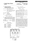
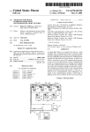
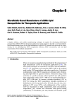
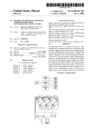
®
Chauvin Arnoux® Inc.
15 Faraday Drive • Dover, NH 03820 USA • (603) 749-6434 • Fax (603) 742-2346 • www.aemc.com
Issue 05“WATTS CURRENT” BULLETIN
Measure Low Resistance
with High Accuracy
Inside this Issue:
■■ Featured Product:
AEMC® Micro-Ohmmeter Model 6240
■■ Customer Support Tip: Connecting
Kelvin Probes to Micro-Ohmmeters
■■ Read SD Card Feature for
PowerPad® III Instruments
■■ AEMC® Interview:
Ed Cunnie, Inside Sales Manager
■■ New Product: Power Adapter for the
Models PEL 102 and PEL 103
Learn how
to correctly
connect your
Kelvin probes
to AEMC®
Micro-Ohmmeters
See pg. 7
Spring 2015
TECHNICAL BULLETIN
CHAUVIN ARNOUX GROUP
Issue 05
“WATTS CURRENT” TECHNICAL BULLETIN
Spring 2015
Featured Product:
AEMC® Micro-Ohmmeter Model 6240
AEMC® Instrument’s Micro-Ohmmeter Model 6240
is a rugged low resistance tester designed for both
indoor and field use. Typical applications for this
instrument include measuring resistance for:
•• Metallic coatings, especially in aeronautics
•• Ground connections and continuity
•• Motors and small transformers
•• Breakers and switches
•• Electrical cables
•• Wire to terminal connections
•• Rail bonds
The Model 6240 employs the Kelvin testing
method to measure very low resistance to within
a quarter of a percent accuracy. Kelvin testing
uses two separate pairs of leads. One pair, called
the “source” leads, provide a known quantity
of constant current. The second pair, called the
potential or “sense” leads, measures voltage.
There is virtually no current flowing through the
sense leads; nearly all the current flows through
the source leads. This allows for a high level of
measurement sensitivity and accuracy when the
load under test is of low resistance. [See also the
article “Measuring Resistance/Impedance with the
Four-Wire Kelvin Method” in the Spring 2014 issue
of the Watts Current Technical Bulletin.]
In this article we explain how to set up and run
a test on the Model 6240. We then show how to
download the test results to your computer using
AEMC’s DataView® software.
For our demonstration, we will connect the
instrument to a 166.6μΩ shunt and run a one
minute test with a current of 10A. To make the
connection, we will use hippo type Kelvin clips.
The Model 6240 also accepts alligator and spring
tip probes. Be sure all leads are correctly attached
to the instrument’s terminals, as explained in a
separate article in this issue of the Technical Bulletin
(see page 7).
When using hippo or alligator probes, ensure that
both jaws are in contact with the device under test
(see below).
The Model 6240 measures resistance from 5μΩ
up to 400Ω. The instrument provides selectable
test currents of 10A, 1A, 100mA, and 10mA; and
includes a polarity reversal function. Up to 99 tests
can be stored in memory.
2
One jaw functions as a source lead, and the other
as a sense lead. Therefore both must be firmly in
contact with the device surface (and both probes
must be in the same orientation) to provide an
accurate measurement.
Issue 05
“WATTS CURRENT” TECHNICAL BULLETIN
Model 6240 User Interface
Before we begin, let’s take a moment to get
acquainted with the Model 6240 user interface.
Spring 2015
Below the dial is the Start/Stop button for starting
and pausing test measurement sessions.
The Model 6240 interface is described in detail in the
user manual that accompanies the instrument.
Taking and Saving a Measurement
We begin our simple demonstration by turning the
selection dial to Set-Up. After a few seconds the first
Set-Up screen appears.
Below the instrument’s LCD are five function
buttons:
•• MEM (Memory) stores the test in the
instrument’s memory where it can be
subsequently viewed on the LCD and
downloaded to a computer running
DataView®. This button also initiates
Auto mode (explained later in this article).
•• CLR (Clear) removes the selected test
from the instrument’s memory.
•• MR (Memory Recall) displays records
stored in memory.
•• ± I (Polarity) reverses the polarity of the
test current, and displays the average of
the two polarity measurements. This is
useful for minimizing the effects of stray
DC currents when measuring very low
resistances. This button also serves as
the Up arrow in user-configurable screens,
such as those displayed in Set-Up mode.
•• Display toggles between displaying current
and displaying voltage measurements.
This button also functions as a Right arrow
in user-configurable screens.
To the right of the LCD is the selection dial. This
turns the instrument ON and OFF, places the
instrument in Set-Up mode, and selects the test
measurement resistance and current range.
Set-Up screens allow you to set several
configuration parameters for the instrument. Use
the Right button to cycle through the screens to
ensure the settings are appropriately configured for
the test you want to run. For example, to check the
instrument’s time, press the Right button once to
display the current time setting. If this is incorrect,
press and hold down the Right button until the
setting blinks. Then use the Up button to change
the setting. Use the Right and Up buttons to make
any other required configuration modifications, as
explained in the Model 6240 user manual.
When the configuration is set, you can take a
resistance measurement. If the resistance you are
testing is unknown, we suggest starting with the
instrument’s highest resistance setting and then
lowering the setting until you obtain meaningful
results. In our demonstration we are using a shunt of
known resistance, so turn the selection dial to “10A
4000μΩ.”
To begin the test, press the Start/Stop button
once. After a moment the resistance and current
measurements appear in the LCD.
3
Issue 05
“WATTS CURRENT” TECHNICAL BULLETIN
Spring 2015
the instrument begins recording a new test each
time you connect the probes, and ends the test
when you disconnect. Tests are automatically
incremented and saved with each connection and
disconnection. This is an ideal test method where
repetitive tests need to be conducted at multiple
points on the device. The spring loaded pencil point
or pistol grip probes work best for this type of test.
As you can see, current is slightly over 10A, and
resistance is approximately 167μΩ in this example
test. Note that you can also view the test voltage by
pressing the Display button.
To end the test, press Start/Stop a second time.
The word HOLD appears on the screen, indicating
the test has been halted. To resume the test, press
Start/Stop.
To save the completed test in the instrument’s
memory, press the MEM button. This displays the
default Object Number and Test Number under
which this test will be saved.
Downloading and Viewing
Test Results in DataView®
With the test saved in the Model 6240’s memory,
you can now download it to a computer, using
AEMC’s DataView® software. To do this, DataView®
with the Micro-Ohmmeter Control Panel must be
installed on your computer. The Micro-Ohmmeter
Control Panel is the primary interface for connecting
with the Model 6240, downloading test results,
and viewing the data on the screen. You can
also use the Control Panel to set up tests, view
measurement data in real-time, and configure the
instrument.
The Model 6240 communicates through a USB
cable that comes with the product. The first time
the cable is connected between the instrument and
the computer, USB drivers will be installed. Wait
until the drivers finish installing before proceeding.
To begin the download procedure, open the Micro-
An Object can contain multiple tests, similar to a
folder containing multiple files. You can accept the
displayed Object and Test numbers, or change
them by pressing the Up button, and then using the
Up and Right buttons to make changes. To save the
test to memory, press the MEM button and hold it
down until the word Done appears.
Stored tests can be viewed in the Model 6240’s
LCD. To do this, press the MR button. This displays
the last test viewed. Press the Up button to display
any other tests in this Object. To view tests stored
in another Object, press the Right button and use
the Up button to select the Object number.
Note that the Model 6240 also provides Auto
mode, initiated by the Auto button. In Auto mode,
4
Ohmmeter Control Panel by clicking its icon
on
the computer’s desktop. When the Control Panel
is open, you can establish a connection between
the computer and the Model 6240. To do this, click
Instrument in the Control Panel menu bar, and then
select the Connect option. The Connection dialog
box appears; which enables you to select the
communication port, the communication rate, and
the instrument model.
Click the Communication port field to display a
drop-down list of available ports, and select the
appropriate one. Next, select the communication
rate. If the Model 6240 is already selected in the
“Instrument model” field, the communication rate
Issue 05
“WATTS CURRENT” TECHNICAL BULLETIN
Spring 2015
is automatically set to 9600 (see the preceding
illustration). Finally, ensure that the appropriate
instrument model number is selected. When you
have completed all three fields in the Connection
dialog, click OK. The Control Panel now connects
to the instrument. When this is completed
successfully, the word Connected appears in the
lower right corner of the Control Panel status bar.
You can now download test results. To do this, click
Instrument in the menu bar and select Download.
After a few moments, the Select Tests dialog box
appears.
When first opened, a test can have a limited amount
of data. You can augment this data by clicking Edit
in the menu bar and then selecting the Edit option.
This displays the Session Summary Properties
dialog box.
This lists all tests currently stored in the instrument.
You can download individual tests by selecting
them, or use the Select All button to download the
entire contents of the instrument’s memory. In our
example, there is only one test stored, so select it
and click Download.
When the download is complete, the navigation
frame on the left side of the Control Panel window
lists the object name, as well as any tests contained
within the object. Clicking on the name of the test
displays its measurement data in the data frame on
the right side of the Control Panel window.
This dialog box consists of four tabs. The first
is named Test, and it lets you enter explanatory
information about the testing session. You can also
enter temperature correction data. This data is used
to calculate the temperature offset, as explained in
the Model 6240 documentation.
The Object tab lets you change the name of the
object in which the test data is stored.
The Operator tab lets you enter information about
the person who conducted the test. To start, click
the Edit button to display the Session Properties
dialog box. This has three tabs, Operator, Site, and
Custom. You can enter information in the Operator
tab, or choose from a list of previously created
operator records, if any. When you select one, the
person’s information automatically populates the
fields on this tab.
5
Issue 05
“WATTS CURRENT” TECHNICAL BULLETIN
Spring 2015
the saved test data.
You can now view the downloaded and edited test
data as a DataView® report. To do this, select the
name of the test listed in the navigation frame. Then
click File in the Control Panel menu bar and choose
Create DataView® report.
When this tab is complete, click OK.
The final tab in the Session Summary Properties
dialog box is labeled Site. Click Edit to display the
Session Properties dialog box. Open the Site tab,
and either complete the displayed fields, or select
an existing name from the site list.
The Custom tab in the Session Properties dialog
box is for adding custom fields to DataView®
reports created from this record. When complete,
click OK to return to the Session Summary
Properties dialog box, and click OK a second
time to save your changes. You can now view the
complete test record. This includes information
about the test operator, the test site, the instrument
model and other test-related information,
data related to the temperature offset, the test
measurement data itself as recorded on the
Model 6240 instrument, and finally any additional
comments.
By default, this report consists of a Cover Sheet
and a Test Summary worksheet. To save the report
to the computer, click File when viewing the report,
and then click Save and specify a location for the
saved report file. Note that DataView® includes a
number of features that enable you to customize
your reports, displaying your test results for a
wide variety of users and purposes. These report
generation features are described in detail in the
DataView® Help.
For more information about the Model 6240, visit
the instrument’s product web page. And be sure
to visit our YouTube channel for videos about the
many products offered by AEMC®.
To save the complete updated test on the
computer, click File in the menu bar and select
Save. You will be prompted to enter a file name for
6
Issue 05
“WATTS CURRENT” TECHNICAL BULLETIN
Spring 2015
Customer Support Tip:
Connecting Kelvin Probes to
AEMC® Micro-Ohmmeters
By Guy Belliveau
AEMC® Instruments offers Kelvin test probes that are designed to work with our Model 6240, Model 6250,
and Model 6292 micro-ohmmeters. We currently stock 13 different part numbers for these probes (visit the
AEMC Storefront for direct purchase).
These Kelvin probes have different combinations of color coding on their leads. AEMC® micro-ohmmeters
also have color-coded terminals on the instrument’s front panel. It’s important to note that the terminal colors
on the instruments do not always correlate with the test lead colors. As a result, connecting the leads is not
always simply a matter of matching colors.
All AEMC® micro-ohmmeters have four terminals. These consist of two pairs of terminals, each containing a
“C” (current sourcing) and a “P” (potential sensing) terminal. One pair is red, and the other pair is black (see
below).
Correspondingly, each AEMC® handheld Kelvin probe has a C lead and a P lead. The C lead must be
connected to the instrument’s C terminal, and the P lead must be connected to the P terminal. For some
probes, the colors of the leads and terminals match, and for others they do not.
The colors of the leads for Kelvin probe Cat# 1017.84 (left) match the colors for the instrument’s terminals.
The leads for Cat# 2118.75 (right) do not match the terminal colors
7
Issue 05
“WATTS CURRENT” TECHNICAL BULLETIN
Spring 2015
The following table lists the Kelvin probes supported by the Models 6240 and 6250, and shows how they
should be connected to the instrument.
Note that these probes are not supported by the Model 6292.
Model 6240 and Model 6250 Kelvin Probes
Cat. #
Image
Probe 1
Leads
Probe 2
Leads
1017.84
red/red
black/black
2118.74
2118.82
2118.75
2118.76
2118.77
2118.78
2118.79
2118.80
8
Comments
For these probes, the
colors of the leads
and terminals match.
Connect the red leads
to the red terminals, and
black leads to the black
terminals.
2118.70
2118.73
Illustration
red/black
red/black
Note that you still
need to be mindful of
the orientation of the
leads. The black lead
connected to C2 and the
red lead connected to
C1 need to be the same
side of the probe jaws
for the most accurate
results.
For these probes, the
colors of the leads and
terminals do not match.
Connect the black
leads to the C terminals
and red leads to the P
terminals (or vice versa).
When connected, both
C leads should be the
same color, and both P
leads should also be the
same color.
Issue 05
“WATTS CURRENT” TECHNICAL BULLETIN
Spring 2015
The following table lists the Kelvin probes supported by the Model 6292, and shows how they should be
connected to the instrument.
Note that these probes are not supported by the Models 6240 and 6250.
Model 6292 Kelvin Probes
Cat. #
Image
2129.87
2129.89
Probe 1
Leads
red/black
Probe 2
Leads
black/black
Illustration
Comments
For these probes,
leads must be
connected to
terminals in
accordance with
thickness rather than
color. The thicker
leads (both of which
are black) connect to
the C terminals. The
thinner leads (one
red, the other black)
connect to the P
terminals, as shown
in the illustration to
the left.
For a visual demonstration of how to connect Kelvin probes to AEMC® micro-ohmmeters, see the YouTube
video “AEMC Micro-Ohmmeter Test Lead Connections”
About the Author:
Guy Belliveau is a Technical Support Specialist
for AEMC® Instruments, Dover NH.
9
Issue 05
“WATTS CURRENT” TECHNICAL BULLETIN
Spring 2015
Read SD Card Feature for
PowerPad® III Instruments
By Bob Cooperman
Note that the SD card contains trend recorded
measurement data only. Snapshot, transient, alarm,
and inrush data is stored in the instrument’s internal
Flash memory, and must still be downloaded via the
PowerPad® III Control Panel and a USB connection.
This article describes the basic steps required to
use the Read SD Card feature, including:
1. Remove the SD card from the instrument.
2. Insert the SD card into your computer, and
download the contents using the PowerPad®
III Control Panel.
3. Replace the SD card in the instrument.
NOTE: This procedure does not apply to
the waterproof Model 8435. Removing
the SD card from the Model 8435 requires
sending the instrument to AEMC® or an
authorized repair facility.
Example shown - PowerPad® Model 8336
The AEMC® PowerPad® III series includes the
Model 8333, Model 8336, and Model 8435.
These portable three-phase power quality
analyzers are designed to measure RMS, many
different types of power and power quality, and
disturbances on electric distribution networks.
Recorded measurement trend data is stored in the
instrument’s removable 2GB SD card.
Until recently, the only way to transfer this data to
a computer has been to connect the instrument
via the USB cable supplied with the product, and
then download the data using DataView® with the
PowerPad® III Control Panel. This process can take
around 20 hours to complete for very large amounts
of data.
The new Read SD Card feature in the PowerPad
III Control Panel now streamlines this process.
For PowerPad® III instruments (except for the
waterproof Model 8435, for which the SD card is
not accessible) running firmware version 4.1 or later,
the Read SD Card option in the Control Panel’s File
menu lets you download the contents of the SD
card directly into your computer.
®
10
Before You Begin
To use the SD Card feature, your computer must be
equipped with an SD card reader. It must also have
DataView® with the PowerPad® III Control Panel
installed.
You will also need the following to remove the SD
card from the instrument:
•• Clean, dry, and well-lighted work surface.
•• Coin or similar implement.
•• Flathead screwdriver.
Before opening the back cover, your PowerPad® III
instrument must be powered OFF, with all probes,
sensors, and the power cord disconnected. This is
important, to prevent the risk of electric shock when
opening the battery compartment.
Issue 05
“WATTS CURRENT” TECHNICAL BULLETIN
Step 1: Removing the SD Card
from the Instrument
Spring 2015
Turn the instrument over and hold the battery as it
slides out of its compartment. Position the battery
out of the way, but do not unplug it.
Place the instrument face down on your work
surface. Put the instrument’s stand in the upright
position, with the stand’s pivoting brace supported
by the two tabs on the back of the instrument (see
the arrow in the illustration below). This ensures that
the brace does not interfere with the removal of the
battery compartment cover.
Locate the SD card slot. The card is held in place
by a flexible tab. While holding this tab down, gently
push the card to the left and release it. This springreleases the card from its slot.
Locate the two fasteners on the battery
compartment cover. Using a coin or similar
implement, turn each fastener 90o counterclockwise
(the fastener slot will now be in the horizontal
position).
Remove the SD card, and locate the writeprevention slider on the left edge of the card. When
the card is first removed from the instrument, it is
in the unlocked position (the slider is positioned
towards the card’s metal pins). To prevent the
card from accidently being overwritten during the
download procedure, you must move the slider to
the LOCK position (see below). The LOCK direction
is away from the metal tabs on the SD card.
Using a flat screwdriver or equivalent, gently
remove the cover from the compartment, taking
care not to damage the plastic cover holder.
11
Issue 05
“WATTS CURRENT” TECHNICAL BULLETIN
Step 2: Downloading the SD Card
Data to the Computer
Insert the card into an available SD card reader slot
on your computer. After a few moments, a prompt
appears asking whether or not you want to format
the SD card. The prompt should include the drive
letter; make note of this drive letter. Click Cancel in
response to this prompt. If you format the card,
you will lose all data stored on it.
Open the PowerPad III Control Panel. In the menu
bar at the top of the screen select File, and then click
the option Read SD Card. This displays the Read
from SD Card dialog box.
®
Spring 2015
instrument; it will download the part of the EN
50160 test data that is not on the SD card, and
combine it with the part that is on the SD card.
If you answer no, it will open the recording as if
it were a simple trend, without the rest of the EN
50160 test data.
Step 3: Replacing the SD Card
Remove the card from the computer. There is
no need to use the Windows eject feature or the
“safely remove hardware” command before doing
so. Move the card’s write protection slider back
to the unlocked position (towards the metal tabs).
Then slide the card back into its slot until it clicks
and locks in place.
Replace the battery in the compartment, and
replace the compartment cover. Be sure the two
tabs on the bottom of the cover are properly
aligned in the slots on the back of the instrument.
Turn the cover fasteners 90º clockwise into
the closed (vertical) position. Finally, close the
instrument’s stand.
Click “Search for SD card drive.” The Control Panel
searches the computer for any available SD cards,
and displays a drop-down list of any card(s) it finds.
To ensure the SD card and/or battery have been
replaced properly; press the instrument’s Power
button. If the instrument does not turn ON,
open the battery compartment and ensure the
battery is properly connected.
With the instrument ON, press the Record
button.
•• If the message “No Memory Card
Installed” appears, the SD card may not be
properly connected in its slot. Turn OFF the
instrument, open the battery compartment,
and ensure the SD card is properly seated
and the spring lock clicks in place.
Select the SD card, and click “Read from SD card.” It
should be the same drive letter that appeared in the
“format” prompt earlier. The Control Panel copies the
contents of the SD card into a Control Panel (.icp) file,
and opens the file in the My Campaigns folder.
If the SD card data includes an EN 50160 test, you
are now asked whether or not you want to download
the complete test. If you answer yes, the next
time the Control Panel is connected to the same
12
If the message “Protected Memory Card” appears,
the write-protection slider is in the LOCK position.
Remove the card and position the slider in the
unlocked position.
About the Author:
Bob Cooperman is a Senior Software Developer
for AEMC® Instruments, Dover, NH.
Issue 05
“WATTS CURRENT” TECHNICAL BULLETIN
AEMC® Interview:
Ed Cunnie, Inside Sales Manager
Many AEMC® customers are familiar with Ed
Cunnie through his numerous training seminars and
presentations, often delivered on-site. Others have
spoken to Ed on the phone to discuss which AEMC®
products best fit their needs. Ed recently assumed the
role of Inside Sales Manager, a newly created position
in which he actively markets and promotes sales of
AEMC’s full product line across North America.
Q. Dropship sales?
A.
It’s a fairly recent trend that’s been brought
about by the internet. The traditional sales
model is for distributors to buy products
from AEMC® and sell them to customers. Our
involvement in the sales process was often
little more than directing the customer to
their local AEMC® distributors, based on the
customer’s zip code.
With the growing popularity of online
purchasing, this model has evolved. There are
now a number of very successful web-based
distributors who basically broker the sale of
our products. The customer orders from the
distributor’s web site, the distributor contacts
AEMC®, and we ship the order directly to the
customer. The product never actually sits on
the distributor’s shelf. This process – AEMC®
shipping the product straight to the customer
– is called a dropship sale. These now
comprise a significant portion of our business.
Q. What role do you play in these sales?
A.
It’s often said that the easiest sale is to an
existing customer. In the case of AEMC®, this
is especially true. Frankly, we provide excellent
products and services, and our customer
satisfaction is very high. As a result, AEMC®
customers are generally very receptive to
doing additional business with us. In my new
role, I reach out to these valuable customers
with the intent to see if there are other sales
opportunities for our products that can help
the customer do their work.
Most of our customers can use multiple
products we provide, including power
analyzers, insulation testers, ground testers,
ancillary items, and so on. As a business
we’re always looking for sales opportunities,
of course, but we’re not simply trying to sell
the customer something they may or may
not really need. I speak with the customer to
learn about their specific requirements, and
make suggestions according – how are you
performing this particular function, did you
know we have a product that can make this
task easier, and so on. I refer to this as an “oh,
by the way” sale – or as it’s more commonly
known, solution selling.
In this interview, Ed discusses his new responsibilities
and how they fit into the ever-evolving sales process.
Q. What are your chief responsibilities at
AEMC® Instruments?
A.
For 15 years, I served as Eastern Regional
Sales Manager, covering an area from
Newfoundland to Florida. During this time I
met with countless customers, travelling all
over to visit their facilities and discuss their
particular issues and requirements. This
experience helped me develop an extensive
knowledge of technologies, products, and
the industry as a whole.
In 2014 I moved into the role of Inside Sales
Manager. This position allows me to leverage
the knowledge I gained as Regional Sales
Manager and apply it to new areas. A key
objective is to explore the possibility of
selling more of our products to our existing
customers through phone contact and
follow up, where necessary, by our field
selling organization. A component of this is
customer follow up for dropship sales.
Spring 2015
13
Issue 05
“WATTS CURRENT” TECHNICAL BULLETIN
It’s also important to be mindful of the
customer’s business size and scope. Many of
our customers are smaller shops, sometimes
consisting of a single person. In these cases,
I suggest products that will provide the most
value while still staying within a limited budget.
Q. In what other ways do you support Inside
Sales?
A.
One responsibility is answering customer
questions about potential product choices.
My job is to help ensure the customer buys
the right product for the purpose they have in
mind. Again, this is all part of solution selling.
For example, we recently received an inquiry
from an aerospace company in California.
They have a large chamber in which they test
their satellites for up to 30 days, subjecting
the equipment to a variety of conditions
that emulate the environment in space.
Unfortunately, during these tests they often
experienced power interruptions that resulted
in a loss of all their recorded test data. They
were interested in purchasing an instrument
to help them solve this problem, but weren’t
really sure which one would be best suited for
their specific purpose. After some discussion
I suggested they purchase a PowerPad® III,
due to its ability to zero in on high-speed
anomalies, and they did.
Another customer inquiry actually resulted in
a new product for AEMC®. A utility company
wanted to measure a wooden utility pole for
leakage current caused by factors such as
brush fires and moisture penetration. Our
Engineering group put together a kit consisting
of a Model 5233 DMM [Digital Multimeter] and
a custom 10’ GroundFlex® sensor. This unique
combination will surely generate sales in areas
subject to forest fires.
Other responsibilities include the follow up
of formal customer quotations. We want to
avoid having a sales opportunity lie dormant
due to any lack of persistence on our part, or
because a customer needs clarification about
something before placing an order. Inquiries
that come in through [email protected] that
require a customer dialog to expedite the
solution are among my daily activities.
14
Spring 2015
In addition, over the years I have developed
a close relationship with a government
laboratory in Washington, DC and will maintain
that liaison going forward. As a result, and
in concert with Terry Brickley, we have been
awarded contracts for the Model 3711 and the
Model 6470-B Ground Tester, and are currently
in the bidding process for the Model CA7027.
Q. Any additional thoughts?
A.
It certainly has been my pleasure being
associated all these years with a company that
consistently design, develops and offers quality
products such as that of AEMC® Instruments.
Issue 05
“WATTS CURRENT” TECHNICAL BULLETIN
Spring 2015
New Product:
Power Adapter for the
Models PEL 102 and PEL 103
The Power Adapter for Models PEL 102 and PEL 103
(Cat # 2137.77) provides power supplied through the
voltage test leads. This enables the instrument to
operate without using the battery or in environments
where a plug-in electrical outlet is unavailable. The
battery remains fully charged and available to supply
power in the event of a disruption to the electrical
distribution system.
The adapter draws power from phase-to-neutral or
phase-to-phase voltage. It also provides isolation
between measurement and instrument power.
Using this feature requires no special preparation or
modification to the instrument. Simply:
1. Insert the adapter into the voltage inputs of
the PEL.
2. Plug the adapter’s power cord into the
instrument’s power supply socket.
3. Connect the voltage leads to the adapter’s
terminals, in the same way you would
connect these leads to the PEL. (The current
leads still connect directly to the instrument.)
Note that the power adapter works with AC 50 and 60Hz distribution systems. You cannot use the adapter
to power the instrument from a DC network, nor from a 400Hz network.
For ordering information, see the AEMC® Instruments Storefront web site at store.aemc.com.
15
Chauvin Arnoux®, Inc. d.b.a. AEMC® Instruments
15 Faraday Drive • Dover, NH 03820 USA
Tel: (800) 343-1391 • (603) 749-6434 • Fax: (603) 742-2346
www.aemc.com • [email protected]
Issue 05 • Spring 2015