1
ACCES I/O PRODUCTS INC
10623 Roselle Street, San Diego, CA 92121
TEL (858)550-9559
FAX (858)550-7322
www.accesio.com
www.acces.io
MODEL AIM-16
USER MANUAL
FILE: MAIM-16.D1e
Notice
The information in this document is provided for reference only. ACCES does not assume any liability
arising out of the application or use of the information or products described herein. This document may
contain or reference information and products protected by copyrights or patents and does not convey any
license under the patent rights of ACCES, nor the rights of others.
IBM PC, PC/XT, and PC/AT are registered trademarks of the International Business Machines Corporation.
Printed in USA. Copyright 1995 by ACCES I/O Products Inc, 10623 Roselle Street, San Diego, CA 92121.
All rights reserved.
Page iii
Warranty
Prior to shipment, ACCES equipment is thoroughly inspected and tested to applicable specifications.
However, should equipment failure occur, ACCES assures its customers that prompt service and support
will be available. All equipment originally manufactured by ACCES which is found to be defective will be
repaired or replaced subject to the following considerations.
Terms and Conditions
If a unit is suspected of failure, contact ACCES' Customer Service department. Be prepared to give the unit
model number, serial number, and a description of the failure symptom(s). We may suggest some simple
tests to confirm the failure. We will assign a Return Material Authorization (RMA) number which must
appear on the outer label of the return package. All units/components should be properly packed for handling
and returned with freight prepaid to the ACCES designated Service Center, and will be returned to the
customer's/user's site freight prepaid and invoiced.
Coverage
First Three Years: Returned unit/part will be repaired and/or replaced at ACCES option with no charge for
labor or parts not excluded by warranty. Warranty commences with equipment shipment.
Following Years: Throughout your equipment's lifetime, ACCES stands ready to provide on-site or in-plant
service at reasonable rates similar to those of other manufacturers in the industry.
Equipment Not Manufactured by ACCES
Equipment provided but not manufactured by ACCES is warranted and will be repaired according to the
terms and conditions of the respective equipment manufacturer's warranty.
General
Under this Warranty, liability of ACCES is limited to replacing, repairing or issuing credit (at ACCES
discretion) for any products which are proved to be defective during the warranty period. In no case is
ACCES liable for consequential or special damage arriving from use or misuse of our product. The
customer is responsible for all charges caused by modifications or additions to ACCES equipment not
approved in writing by ACCES or, if in ACCES opinion the equipment has been subjected to abnormal use.
"Abnormal use" for purposes of this warranty is defined as any use to which the equipment is exposed other
than that use specified or intended as evidenced by purchase or sales representation. Other than the above,
no other warranty, expressed or implied, shall apply to any and all such equipment furnished or sold by
ACCES.
Page iv
Table of Contents
Notice.. . . . . . . . . . . . . . . . . . . . . . . . . . . . . . . . . . . . . . . . . . . . . . . . . . . . . . . . . . . . . . iii
Warranty. . . . . . . . . . . . . . . . . . . . . . . . . . . . . . . . . . . . . . . . . . . . . . . . . . . . . . . . . . . . iv
Chapter 1: Introduction. . . . . . . . . . . . . . . . . . . . . . . . . . . . . . . . . . . . . . . . . . . . . . . 1-1
Specifications. . . . . . . . . . . . . . . . . . . . . . . . . . . . . . . . . . . . . . . . . . . . . . . . . . . . . . . . . . 1-2
Chapter 2: Installation . . . . . . . . . . . . . . . . . . . . . . . . . . . . . . . . . . . . . . . . . . . . . . . 2-1
CD Installation.. . . . . . . . . . . . . . . . . . . . . . . . . . . . . . . . . . . . . . . . . . . . . . . . . . . . . . . . . 2-1
3.5-Inch Diskette Installation. . . . . . . . . . . . . . . . . . . . . . . . . . . . . . . . . . . . . . . . . . . . . . . 2-1
Directories Created on the Hard Disk. . . . . . . . . . . . . . . . . . . . . . . . . . . . . . . . . . . . . . . . 2-2
Installation of the AIM-16.. . . . . . . . . . . . . . . . . . . . . . . . . . . . . . . . . . . . . . . . . . . . . . . . . 2-4
Option Selection. . . . . . . . . . . . . . . . . . . . . . . . . . . . . . . . . . . . . . . . . . . . . . . . . . . . . . . . 2-7
Gain Selection.. . . . . . . . . . . . . . . . . . . . . . . . . . . . . . . . . . . . . . . . . . . . . . . . . . . . . . . . . 2-7
Channel Selection. . . . . . . . . . . . . . . . . . . . . . . . . . . . . . . . . . . . . . . . . . . . . . . . . . . . . . . 2-9
Current Inputs. . . . . . . . . . . . . . . . . . . . . . . . . . . . . . . . . . . . . . . . . . . . . . . . . . . . . . . . . . 2-9
RTD Sensor Selection.. . . . . . . . . . . . . . . . . . . . . . . . . . . . . . . . . . . . . . . . . . . . . . . . . . 2-10
Power Supply Selection.. . . . . . . . . . . . . . . . . . . . . . . . . . . . . . . . . . . . . . . . . . . . . . . . . 2-10
Calibration and Test. . . . . . . . . . . . . . . . . . . . . . . . . . . . . . . . . . . . . . . . . . . . . . . . . . . . 2-12
Chapter 3: Software.. . . . . . . . . . . . . . . . . . . . . . . . . . . . . . . . . . . . . . . . . . . . . . . . . 3-1
Drivers.. . . . . . . . . . . . . . . . . . . . . . . . . . . . . . . . . . . . . . . . . . . . . . . . . . . . . . . . . . . . . . . 3-1
Sample Programs. . . . . . . . . . . . . . . . . . . . . . . . . . . . . . . . . . . . . . . . . . . . . . . . . . . . . . . 3-1
SETMUX. . . . . . . . . . . . . . . . . . . . . . . . . . . . . . . . . . . . . . . . . . . . . . . . . . . . . . . . . . . . . . 3-1
Chapter 4: Sensor Interface. . . . . . . . . . . . . . . . . . . . . . . . . . . . . . . . . . . . . . . . . . . 4-1
Considerations for Thermocouples. . . . . . . . . . . . . . . . . . . . . . . . . . . . . . . . . . . . . . . . . .
Considerations for RTD Sensors.. . . . . . . . . . . . . . . . . . . . . . . . . . . . . . . . . . . . . . . . . . .
Considerations for Strain Gage Sensors. . . . . . . . . . . . . . . . . . . . . . . . . . . . . . . . . . . . . .
Considerations for Current Inputs. . . . . . . . . . . . . . . . . . . . . . . . . . . . . . . . . . . . . . . . . . .
Considerations for Other Voltage Inputs. . . . . . . . . . . . . . . . . . . . . . . . . . . . . . . . . . . . . .
4-1
4-2
4-2
4-3
4-3
Appendix A: Cabling and Connector Information.. . . . . . . . . . . . . . . . . . . . . . . . A-1
Input Connector Pin Assignments. . . . . . . . . . . . . . . . . . . . . . . . . . . . . . . . . . . . . . . . . . . A-1
Page v
List of Figures
Figure 1-1: AIM-16 Block Diagram. . . . . . . . . . . . . . . . . . . . . . . . . . . . . . . . . . . . . . . . . . . . . 1-3
Figure 2-1: Use of CAB-37Y Cables. . . . . . . . . . . . . . . . . . . . . . . . . . . . . . . . . . . . . . . . . . . 2-6
Figure 2-2: AIM-16 Option Selection Map. . . . . . . . . . . . . . . . . . . . . . . . . . . . . . . . . . . . . . 2-11
List of Tables
Table 2-1: AIM-16 Gain Table. . . . . . . . . . . . . . . . . . . . . . . . . . . . . . . . . . . . . . . . . . . . . . . . 2-8
Table A-1: Connector Pin Assignments. . . . . . . . . . . . . . . . . . . . . . . . . . . . . . . . . . . . . . . . . A-2
Page vi
Chapter 1: Introduction
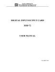
Analog Input Multiplexer, Model AIM-16, is installed external to the computer. The AIM-16
accepts, preamplifies, and multiplexes up to 16 analog input signals before passing them to an
analog-to-digital converter typically located in an I/O slot in a PC/XT/AT type host computer. This
allows direct sensor interface without jeopardizing the quality of gathered data. The AIM-16
provides screw-terminal terminations and input signal conditioning for a variety of sensors including
thermocouples (J,K,T,E,S,R, and B), three-wire RTDs (both for 392- and 385-alpha), and strain
gages as well as DC voltage and current inputs. For strain gage applications, +10V at up to 220mA
excitation voltage for the strain gages is provided by the ACCES Model AD12-8 analog-to-digital
converter through the AIM-16. That excitation voltage is available at a 2-position screw-terminal
block labeled REF OUT.
An input, when selected by the input multiplexer, is filtered, amplified, and, if required, level shifted.
After this processing, the signal is supplied to an output channel where it is passed to the
analog-to-digital converter. The A/D converter digitizes the DC signal and presents it to the
computer CPU for further processing and/or display.
A major feature of this card is that it can be used with mixed-range analog inputs. The AIM-16
provides extensive programming flexibility for both hardware and software configuration. Four
digital input lines are used for channel selection and three digital input lines are used for gain
selection. Gains may be selected by software or manually by switch. When selected manually, the
gain setting chosen applies to all input channels.
Software included with model AD12-8 analog-to-digital converter facilitates interface to the
AIM-16. That software includes setup programs, drivers, and sample programs. Read sections
Installation and Software for more details.
The AIM-16 card may be used as part of a large data acquisition system. A system may comprise
one to eight of these cards, all interconnected on the same output bus because each card has two
parallel input/output connectors. For thermocouple measurements, each card may provide it's own
reference junction compensation at input IN0 by using jumpers marked "TMP" as described in
Installation. Also, for thermocouple applications, a break-detect circuit is activated by installation
of a pair of shorts for each thermocouple input channel.
Option P consists of a DC-DC converter which operates from the +5VDC computer power supply
and provides isolated ±15VDC for use by the analog circuits on AIM-16. This option is particularly
useful if the ±12VDC computer power is noisy and/or is marginally low.
Model AIM-16I has current-sensing resistors installed for use in 4-20mA applications. Further, it
has also been modified so that maximum resolution is provided at the A/D converter. The
modifications that are made include introduction of an offset and addition of a gain adjustment pot,
so that full 12-bit resolution is provided. Model AIM-16R is specifically modified to provide the
best possible accuracy for RTD inputs.
Manual MAIM-16.D1e
Page 1-1
AIM-16 Manual
Specifications
Analog Inputs and Outputs
•
•
•
•
•
•
•
•
•
•
•
•
•
•
•
•
•
•
•
Input Channels:
16 Differential Analog Input Channels per AIM-16.
Output Channels:
Analog Output assignable to 1 of 8 Output Channels.
Common Mode Rejection:
125 db for gains above 100.
90 db for gain = 1.
Output Rating:
5mA at ±10VDC or ±5VDC.
Gain Nonlinearity:
±0.005%.
Temp. Coefficient:
5 ppm/ EC.
Overvoltage:
Continuous: 70V peak-to-peak, 35VDC.
Sensors:
Thermocouples, with break detect provided.
RTDs, with excitation and offset provided.
Strain gages, with ratiometric outputs.
Voltage and current inputs.
Reference Junction:
Temperature Scale Factor: +24.4mV/ EC., 0.0VDC @ 0 EC.
Reference junction temperature output assignable as an input to
Analog Input Channel #0, or to any Output Channel.
Preamplifier:
12 Analog Gains ranging from 0.5 to 1000.
Programmable gains selected by computer, channel by channel.
Manual gains selected by DIP switch one gain setting for all channels.
Three TTL digital inputs for gain selection.
Control Inputs:
Four TTL digital inputs for channel selection.
Terminations: Analog inputs: Plug-on screw terminal blocks for 12-22 AWG wire.
Digital Input/Analog Output: 37-pin Sub-D connector.
Environmental
•
•
•
•
•
Operating Temp:
Storage Temp:
Humidity:
Size:
Power Required:
Page 1-2
0 EC. to 65 EC.
-40 EC. to + 100 EC.
0 to 90% RH non-condensing.
8.0 inches long, 4.75 inches wide, 0.75 inches high.
+5VDC: 20mA typical, with option P, DC to DC converter,
+5VDC: 125mA max..
+12VDC: 10mA typical.
-12VDC: 10mA typical.
Manual MAIM-16.D1e
Figure 1-1: AIM-16 Block Diagram
Manual MAIM-16.D1e
Page 1-3
AIM-16 Manual
Page 1-4
Manual MAIM-16.D1e
Chapter 2: Installation
The software provided with this card is contained on either one CD or multiple diskettes and must
be installed onto your hard disk prior to use. To do this, perform the following steps as appropriate
for your software format and operating system. Substitute the appropriate drive letter for your
CD-ROM or disk drive where you see d: or a: respectively in the examples below.
CD Installation
DOS/WIN3.x
a.
b.
c.
d.
Place the CD into your CD-ROM drive.
Type d:K to change the active drive to the CD-ROM drive.
Type installK to run the install program.
Follow the on-screen prompts to install the software for this card.
WIN95/98/NT
a.
b.
c.
Place the CD into your CD-ROM drive.
The CD should automatically run the install program after 30 seconds. If the install program
does not run, click START | RUN and type d:install, click OK or press K.
Follow the on-screen prompts to install the software for this card.
3.5-Inch Diskette Installation
As with any software package, you should make backup copies for everyday use and store your
original master diskettes in a safe location. The easiest way to make a backup copy is to use the DOS
DISKCOPY utility.
In a single-drive system, the command is:
diskcopy a: a:K
You will need to swap disks as requested by the system.
In a two-disk system, the command is:
diskcopy a: b:K
This will copy the contents of the master disk in drive A to the backup disk in drive B.
Manual MAIM-16.D1e
Page 2-1
AIM-16 Manual
To copy the files on the master diskette to your hard disk, perform the following steps.
a.
Place the master diskette into a floppy drive.
b.
Change the active drive to the drive that has the diskette installed. For example, if the
diskette is in drive A, type a:K.
c.
Type installK and follow the on-screen prompts.
Directories Created on the Hard Disk
The installation process will create several directories on your hard disk. If you accept the
installation defaults, the following structure will exist.
[CARDNAME]
Root or base directory containing the SETUP.EXE setup program used to help you configure
jumpers and calibrate the card.
DOS\PSAMPLES:
DOS\CSAMPLES:
Win32\language:
A subdirectory of [CARDNAME] that contains Pascal samples.
A subdirectory of [CARDNAME] that contains "C" samples.
Subdirectories containing samples for Win95/98 and NT.
WinRisc.exe
A Windows dumb-terminal type communication program designed for RS422/485 operation.
Used primarily with Remote Data Acquisition Pods and our RS422/485 serial communication
product line. Can be used to say hello to an installed modem.
ACCES32
This directory contains the Windows 95/98/NT driver used to provide access to the hardware
registers when writing 32-bit Windows software. Several samples are provided in a variety of
languages to demonstrate how to use this driver. The DLL provides four functions (InPortB,
OutPortB, InPort, and OutPort) to access the hardware.
This directory also contains the device driver for Windows NT, ACCESNT.SYS. This device driver
provides register-level hardware access in Windows NT. Two methods of using the driver are
available, through ACCES32.DLL (recommended) and through the DeviceIOControl handles
provided by ACCESNT.SYS (slightly faster).
Page 2-2
Manual MAIM-16.D1e
SAMPLES
Samples for using ACCES32.DLL are provided in this directory. Using this DLL not only
makes the hardware programming easier (MUCH easier), but also one source file can be used
for both Windows 95/98 and WindowsNT. One executable can run under both operating
systems and still have full access to the hardware registers. The DLL is used exactly like any
other DLL, so it is compatible with any language capable of using 32-bit DLLs. Consult the
manuals provided with your language's compiler for information on using DLLs in your specific
environment.
VBACCES
This directory contains sixteen-bit DLL drivers for use with VisualBASIC 3.0 and Windows 3.1
only. These drivers provide four functions, similar to the ACCES32.DLL. However, this DLL is
only compatible with 16-bit executables. Migration from 16-bit to 32-bit is simplified because of
the similarity between VBACCES and ACCES32.
PCI
This directory contains PCI-bus specific programs and information. If you are not using a PCI card,
this directory will not be installed.
SOURCE
A utility program is provided with source code you can use to determine allocated resources at
run-time from your own programs in DOS.
PCIFind.exe
A utility for DOS and Windows to determine what base addresses and IRQs are allocated to
installed PCI cards. This program runs two versions, depending on the operating system. Windows
95/98/NT displays a GUI interface, and modifies the registry. When run from DOS or Windows3.x,
a text interface is used. For information about the format of the registry key, consult the
card-specific samples provided with the hardware. In Windows NT, NTioPCI.SYS runs each time
the computer is booted, thereby refreshing the registry as PCI hardware is added or removed. In
Windows 95/98/NT PCIFind.EXE places itself in the boot-sequence of the OS to refresh the registry
on each power-up.
This program also provides some COM configuration when used with PCI COM ports. Specifically,
it will configure compatible COM cards for IRQ sharing and multiple port issues.
WIN32IRQ
This directory provides a generic interface for IRQ handling in Windows 95/98/NT. Source code
is provided for the driver, greatly simplifying the creation of custom drivers for specific needs.
Samples are provided to demonstrate the use of the generic driver. Note that the use of IRQs in
near-real-time data acquisition programs requires multi-threaded application programming
techniques and must be considered an intermediate to advanced programming topic. Delphi, C++
Builder, and Visual C++ samples are provided.
Manual MAIM-16.D1e
Page 2-3
AIM-16 Manual
Findbase.exe
DOS utility to determine an available base address for ISA bus , non-Plug-n-Play cards. Run this
program once, before the hardware is installed in the computer, to determine an available address
to give the card. Once the address has been determined, run the setup program provided with the
hardware to see instructions on setting the address switch and various option selections.
Poly.exe
A generic utility to convert a table of data into an nth order polynomial. Useful for calculating
linearization polynomial coefficients for thermocouples and other non-linear sensors.
Risc.bat
A batch file demonstrating the command line parameters of RISCTerm.exe.
RISCTerm.exe
A dumb-terminal type communication program designed for RS422/485 operation. Used primarily
with Remote Data Acquisition Pods and our RS422/485 serial communication product line. Can be
used to say hello to an installed modem. RISCTerm stands for Really Incredibly Simple
Communications TERMinal.
Installation of the AIM-16
The AIM-16 is installed external to the host computer. It provides screw-terminal termination for
input analog wiring, and multiplexing and preamplification for input signals. Multiplexed and
amplified signals are then passed from the AIM-16 to an analog-to-digital converter via a
37-conductor ribbon cable.
The screw-terminal blocks used to connect analog input wires can be removed from the card to
facilitate wire installation. After the wiring has been installed, the terminal blocks can then be
plugged back onto the card. Inputs to the AIM-16 are labelled IN0 through IN15. Note that, for
thermocouple temperature measurements, IN0 may be used as the input channel for the on-board
reference junction sensor, so that reference junction compensation may be accomplished
Note
No input may be connected to IN0 when the TMP jumpers are installed.
Page 2-4
Manual MAIM-16.D1e
Input connections are labeled "+", "GND", and "-". Shields should be connected to the "GND"
terminal if not grounded at the sensor end. Three-wire RTD connections can be made as follows:
connect RTD wires +V and +I to the "+" terminal on the AIM-16, connect RTD wire -V to the "-"
terminal, and connect RTD wire -I to the "GND" terminal. To assure that there is minimum
susceptibility to EMI, proper EMI cabling techniques (twisted-pair wiring and, in extreme cases
shielded wiring) must be used on input wiring.
If the precision 10V reference voltage from the A/D converter is to be used by external circuits,
make connections to the two-position screw terminal labeled REF OUT. Then, connect a cable
between the 37-pin connector on the card and the A/D converter.
As many as eight AIM-16 cards, or 128 channels may be serviced by one analog-to-digital converter
card. The AIM-16 cards in the system are "daisy-chained" together by 37-conductor ribbon cables
plugged on each card to two parallel 37-pin Sub-D connectors. The address of the AIM-16 card is
established by selecting an output channel via a jumper installed at location OV0 to OV7.
The ribbon cable that interconnects AIM-16 to the AD12-8 also provides computer power (via the
AD12-8) to the AIM-16. If Option P is installed on your AIM-16(s), 5V computer power is used by
that option to generate isolated ±15V for the analog circuits on AIM-16 (Otherwise, ±12V computer
power is used.). Since each AIM-16 can draw up to 125mA of current when Option P is installed,
it is desirable to keep the total cable length from the A/D to the furthest AIM-16 as short as possible.
You can tell if Option P is installed on your AIM-16(s) by looking at the lower-left quadrant of the
board. If Option P is not installed, then there will be components absent in that area. If long cable
length is required, you can use an external +5VDC power supply and locate it close to the AIM-16
to be powered. This, of course, will necessitate disconnecting the +5VDC computer power.
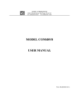
Also, if Option P is included on your card, it is desirable to have no more than three AIM-16s in any
one "chain"; particularly if the REF OUT voltage is to be used as excitation for sensors. For
applications where multiple AIM-16s are to be used, CAB37-18Y cables can be used. That cable
provides ability to branch to two other AIM-16s. For example, consider the case where five
AIM-16s are needed. In this case two CAB37-18Y and one CAB37-18 can be used as shown below.
Manual MAIM-16.D1e
Page 2-5
AIM-16 Manual
Figure 2-1: Use of CAB-37Y Cables
Page 2-6
Manual MAIM-16.D1e
Option Selection
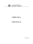
AIM-16 options are selected either by the DIP switch for High Offset and Gain setup, or by
installing plug-in jumpers or solder shunts between labeled points for other options. Refer to Option
Selection Map for the location of the jumper, short, and switch selections discussed below. The
SETMUX program included with AD12-8 is a special program to assist you in setting up the card.
The program uses a menu and illustrations to make it easy to select jumper and switch choices. For
further information on this program see Software. If it is necessary to reconfigure a card, it is
important to remove any jumper, short, or current resistor not required by the new configuration.
Output Range
A switch labeled G/2 (Switch 1 of DIP switch S1) selects the full scale output of the AIM-16 board
and divides the overall gain by two. When G/2 is on, the maximum usable output of AIM-16 is ±5V.
Gain Selection
The AIM-16 may be operated in the programmable gain mode, the manual gain mode or a
combination of the two. The following sections detail the setup for each mode cf. AIM-16 Gain
Table lists the switch positions and resulting gains.
Programmable Gain Mode
To select the Programmable Gain Mode of operation, the following switch settings are required:
Switches:
Switches:
GP0, GP1, GP2ON
GM0, GM1, GM2OFF
In this mode, gains are determined by the state of digital inputs G0, G1, and G2, at I/O connector
pins 3, 5, and 6 respectively. By manipulating the digital input bits from software, gains may be
programmed on a channel-by-channel basis. See AIM-16 Gain Table for the states of G0, G1 and
G2 required for the desired gain.
Manual Gain Mode
To select the Manual Gain Mode of operation, the following switch settings are required:
Switches:
Switches:
GP0, GP1, GP2OFF
GM0, GM1, GM2Depending on gain
In this mode, gains are determined by the position of switches GM0, GM1, and GM2. See AIM-16
Gain Table for the positions of GM0, GM1 and GM2 required for the desired gain.
Manual MAIM-16.D1e
Page 2-7
AIM-16 Manual
Combination of Gain Mode
In instances where less than three digital input control lines are available for setting programmable
gains, a combination of manual and programmable gain may be used. One programmable line gives
selection of two gains; two lines gives four available gains; and three the entire eight.
The switch locations marked GP0, GP1,and GP2 correspond to digital input bits G0, G1, and G2
respectively. Any of the digital input bits that are not software supported, should have the
corresponding GP switch set to OFF. The corresponding GM switch should be set ON or OFF as
desired. For example, if only digital inputs G0 and G1 are available, switch GP2 would be set OFF.
If GM2 is set to ON, then gain codes 0, 1, 2, 3 would be available as programmable gains, and if
GM2 is set to OFF, then gain codes 4, 5, 6 ,7 would be available as programmable gains. See
AIM-16 Gain Table for other combinations.
AIM -16 Gain M ode
Programmable Gains
Resulting Gain
Gain
Code
M anual Gains
G2
G1
G0
GM 2
GM 1
GM 0
0
0
0
ON
ON
ON
0
0
1
ON
ON
0
1
0
ON
0
1
1
1
0
1
G/2 Switch
OFF
ON
0
1
½
OFF
1
2
1
OFF
ON
2
10
5
ON
OFF
OFF
3
50
25
0
OFF
ON
ON
4
100
50
0
1
OFF
ON
OFF
5
200
100
1
1
0
OFF
OFF
ON
6
400
200
1
1
1
OFF
OFF
OFF
7
1000
500
Table 2-1: AIM-16 Gain Table
Page 2-8
Manual MAIM-16.D1e
Channel Selection
This option selects which AD12-8 A/D input channel will be used by the AIM-16.
Install a jumper in a one of the positions labeled OV0 through OV7. ("OV" stands for output
voltage.) This channel must not be used by any other AIM-16, or reference junction in the system.
Usually, the first AIM-16 in a system is set to OV0. If a second AIM-16 is to be used, you can set
it's jumper to OV1, a third to OV2, etc.
Reference Junction Temperature Input Channel Selection
When making thermocouple temperature measurements, it is normally desired to assign the
Reference Junction Temperature to AIM-16 Input Channel IN0. To configure this, install two
jumpers in selection points labeled TMP. These points are located near the Input Channel IN0. Do
not connect any other input or sensor to channel IN0, and do not install break-detection shorts B0
or RTD Sensor Selection shorts R0. (See Thermocouple Break Detect Selection and RTD Sensor
Selection sections.)
If you desire to assign the Reference Junction Temperature directly to an AD12-8 input channel
instead of AIM-16 channel IN0, install a jumper in a selection point labelled OT0 through OT7.
("OT" stands for output temperature.) However, remember that if you do this, this AD12-8 input
channel used must not be used for any other input by this or any other card in the system.
Thermocouple Break Detect Selection
If you wish to use the break-detect feature for a given input channel it is necessary to install shorts
in two selection points both labeled B"n", where "n" is the AIM-16 input channel number. These
points are located near the appropriate channel input. Use this selection only for thermocouple
inputs. With the shorts installed, an open thermocouple condition will cause a full-scale negative
voltage output on that channel.
Current Inputs
If 4-20mA or other current inputs are to be used. Resistors may be added to points labeled IR1-IR16
on the AIM-16 card. Please see Sensor Interface, Considerations for Current Inputs for more
information.
Manual MAIM-16.D1e
Page 2-9
AIM-16 Manual
RTD Sensor Selection
To configure a channel for RTD operation, install shorts in two selection points both labeled R"n",
where "n" is the channel number. These points are all located near the edge of the board furthest
from the connectors in the screw-terminal input area.
RTD Output Offset
For a board dedicated to RTD sensors, a negative output offset may be selected by installing a
jumper in the OFST position of the programming point labeled "OFST STD". This option is used
in cases where you wish to extend the range of an RTD channel.
If this feature is used, then the DIP switch S1 position labeled OSH determines the amount of the
offset. With OSH set ON, the offset is -10V and with OSH set OFF, the offset is -5V. See the
Considerations for RTD Sensors section in Sensor Interface of this manual for further information
on using RTD sensors.
Power Supply Selection
If you have ordered an AIM-16 with the P option (AIM-16P), there are two power supply jumpers.
These are labelled -VS and +VS. On the AIM-16P, the jumpers are installed in the +15V and -15V
positions. Moving these jumpers to the +12V and the -12V positions disables the on-board power
supply and connects the power supplied at the external I/O connector, pin1 for +VS and pin 20 for
-VS. The maximum allowable external voltage ±18V. It is mandatory that only a single +VS and
a single -VS jumper be used. When an AIM-16 is purchased without the P option, two shorts are
soldered at the -12 and +12 positions.
Page 2-10
Manual MAIM-16.D1e
Figure 2-2: AIM-16 Option Selection Map
Manual MAIM-16.D1e
Page 2-11
AIM-16 Manual
Calibration and Test
All ACCES cards are calibrated prior to shipment. However, periodic calibration of AIM-16 is
recommended to retain full accuracy. The calibration interval depends to a large extent on the type
of service that the card is subjected to. For environments where there are frequent large changes of
temperature and/or vibration, a three-month interval is suggested. For laboratory or office
conditions, six months to a year is acceptable.
A 4-1/2 digit digital multimeter is required as a minimum to perform satisfactory calibration. Also,
a voltage calibrator or a stable, noise-free, DC voltage source that can be used in conjunction with
the digital multimeter is required.
Calibration is performed using the SETMUX program supplied with the AD12-8. This program will
lead you through the set up and calibration procedure with prompts and graphic displays that show
the settings and adjustment trim pots. This calibration program also serves as a useful test of the
AIM-16 functions and can aid in troubleshooting if problems arise.
Calibration Procedure
The AIM-16 card has five potentiometers RP1 through RP5, which are used for calibration. These
potentiometers have the following functions:
d.
e.
f.
g.
h.
RP1 sets an output offset of the programmable gain amplifier (U13) to zero.
RP2 sets an input offset of the programmable gain amplifier (U13) to zero.
RP3 sets the level of the +10V regulated supply.
RP4 sets the output of the local reference junction temperature sensor.
RP5 is a fine gain adjust and provides precise gain setting capability.
The following procedure is brief and is intended for use in conjunction with the calibration part of
the SETMUX program.
1.
2.
3.
4.
5.
6.
7.
8.
9.
Page 2-12
Start the calibration program by typing SETMUX and press the ENTER key at the DOS
prompt.
Use the relevant menu selection to assign your AIM-16 to a channel of the AD12-8.
Use the arrow key to select option 6) Calibrate MUX, then press the ENTER key.
Now select which AIM-16 to calibrate and press ENTER.
You will be presented with an initial setup for the AIM-16, ensure that your card is set this
way then press ENTER.
Use the arrow key to select option 1. Adjust RP3, from the menu at the top left hand corner
of the screen.
Following the instructions on the screen, perform the RP3 adjustment
Repeat steps 6) and 7) for RP4, RP1, RP2, and RP5.
This completes the calibration procedure.
Manual MAIM-16.D1e
Chapter 3: Software
The AIM-16 does not have software included with it, as software for a system is largely dependent
upon the A/D card used. The AD12-8 A/D card has a full range of software included with it that
includes support for the AIM-16 as follows. See "Directories Created on the Hard Disk" in the
Installation section for a complete software description.
Drivers
Hardware drivers included with the AD12-8 are designed to use the advanced features of the AIM-16
such as programmable gains and on-board reference-junction compensation. The drivers support
"C", Pascal, QuickBASIC and interpreted BASIC. In addition, a driver is provided in DLL form for
Windows applications
The driver also supports a point list, which allows assignment of point addresses with gain, in any
order desired. This allows A/D points in the system to be scanned in any order.
Sample Programs
Two sample programs directly use the AIM-16. SAMPLE2 performs timer-driven interrupts using
all channels of a single AIM-16. This program can be easily modified to support the maximum
number of eight AIM-16s.
SAMPLE3 performs similar functions to SAMPLE2 but uses the SETUP.CFG configuration file to
setup the driver. If you compare the two samples, you will see the substantial decrease in program
code required when using this auto configuration.
SETMUX
The SETMUX setup utility program provides a graphical reference to assist you in configuring your
AIM-16 for the various features provided by this card. The setup program allows you to assign
AIM-16s or reference junctions to any of the eight A/D channels.
After you assign your AIM-16s to their respective A/D channels, you may make individual channel
assignments for the various types of inputs supported, such as thermocouples or voltage inputs using
any of the programmable gains supported.
Upon exiting the SETMUX program, the setup and configuration information is stored in a file
called SETUP.CFG. The drivers or your own application program can then use this file to determine
the configuration of your system.
SETMUX also provides for calibration of your AIM-16. See the Calibration and Test section of
Installation for instructions on using this feature.
Manual MAIM-16.D1e
Page 3-1
AIM-16 Manual
Page 3-2
Manual MAIM-16.D1e
Chapter 4: Sensor Interface
Before attempting to program or set up the AIM-16, the overall system of which the AIM-16 is a part
should be defined. The AIM-16 provides the system's interface to the various sensors which supply
data. We suggest that you make a list of sensors by type and location. Where practical, sensors of
one type should be grouped on the AIM-16 card to simplify programming.
Considerations for Thermocouples
It is important that the junction temperature from each card be used in computing the temperature
measured by each thermocouple serviced by that card. In order to minimize errors, the junction
temperature sensor is physically located at a place central to all thermocouple connections. The
junction temperature sensor input is normally jumpered to input channel IN0 of each card. A
selection of Gain=1 is suggested for that channel, as it will produce nominal 24.4 mV/ EC. If the
AIM-16 is not enclosed (e.g., in ACCES' T-Box), then care should be taken that there is not air
blowing across the AIM-16. Moving air can cause a small temperature differential, which results
in a "reference junction error".
A total of eight AIM-16 cards per system may be used with an AD12-8. Thus, up to 120
thermocouple inputs can be accommodated (Eight analog input channels used for reference junction
overhead).
An open thermocouple or "break-detect" signal is available and may be activated by installing two
shorts at each channel where break detect is desired. Break-detect short locations are labelled B1
through B16. For example, install two shorts at the two locations labelled B2 in order to enable the
break-detect feature for channel 2. Now, when an open or missing thermocouple is detected, a
full-scale negative output will be provided on channel 2.
A jumper should be installed in the STD position of the programming point labeled "OFST STD".
The OFFSET feature is used for RTDs, for 4-20mA current measurement, and other current
measurements. This feature will be discussed under appropriate paragraphs on the following pages.
Manual MAIM-16.D1e
Page 4-1
AIM-16 Manual
Considerations for RTD Sensors
Three-wire connection may be applied to an RTD sensor by adding two shorts per channel for each
sensor served. The locations for these shorts are labelled R0 through R15. For example, install two
shorts in the two locations labeled R2 if an RTD sensor is used at channel 2.
For extended range and resolution of measurements, it is common practice in RTD processing to
offset the sensor output in a negative direction. The AIM-16 allows a negative 10V offset, so that
a zero input to a channel provides a -10V output. In order to enable this feature install a jumper in
the OFST position of the programming point labeled OFST STD and place the DIP switch labeled
OSH in the ON position.
If the host A to D card is rated at ±5V full scale, install the OFST STD jumper as above but place
the OSH switch in the OFF position. This will reduce the offset to -5V.
While this offset increases the range and resolution of RTD operation, remember that it is a
selection that affects all channels on a given card.
Connections to an RTD sensor are as follows: the V+, I+ lead to the "+" input; the V- lead to the "-"
input; and the I- to the "GND" input.
If all of your sensors are RTDs, model AIM-16R is designed specifically for RTDs.
Considerations for Strain Gage Sensors
A ratiometric reading of a strain gage sensor requires input to two channels of an AIM-16 card. One
channel measures the sensor excitation while the other channel reads the sensor output. The host
computer computes the output as a ratio of the sensor output to sensor excitation. This requires
different gains for each signal, nominally a gain of 1 for the excitation and 200 for the signal. Thus,
strain gage measurement requires the use of programmable gain on an AIM-16 board.
Excitation for the strain gage(s) is available at a screw terminal block on the AIM-16. That
excitation is derived from the AD12-8's precision 10V reference voltage and can supply over 200mA
current.
A jumper should be installed in the STD position of the programming point labeled "OFST STD".
When the STD position is selected, no offset is produced.
Page 4-2
Manual MAIM-16.D1e
Considerations for Current Inputs
The AIM-16 card has provisions for reading input current. Reserved space and board connections
are available for 16 precision resistors. To utilize this provision, it is only necessary to install a
resistor of the proper value and set the gain appropriately for each channel to be used for current
input.
When all inputs are designated for sensing 4-20mA current, it is beneficial to increase resolution by
providing offset. To accomplish this, install a jumper in the OFST position of the programming
point labelled "OFST STD". Alternatively, if the A/D card operates on ±10V range, set DIP switch
#2 "on" ; i.e. OSH (offset-high) position.
If the AIM-16 that you have is model AIM-16I, then it already has the current-sensing resistors
installed. Further, it has also been modified so that maximum resolution is provided at the A/D
converter. The modifications that are made include introduction of an offset and addition of a gain
adjustment pot.
To better understand the modifications, consider the following. If the A/D converter input range is
±5V, the AIM-16 amplifier gain is 1, and a 250-ohm resistor is used, then a 4-20mA current input
would yield voltages of +1V to +5V at the AIM-16 output. Only 40% of the A/D converter range
would be used! To accomplish better resolution, it is necessary to introduce an offset and amplifier
gain. For example, if a -5V offset is introduced and the amplifier gain is increased to 2, then the
output would be -3V to +5V. But that is still only 80% of the A/D converter's range
So, to cover the full range (and thus realize maximum resolution), an additional offset is required
to accommodate the 4mA "live zero". On the AIM-16I, standard 200-ohm (0.1%) resistors are used
in place of 250-ohm resistors. This would yield +2.496V to +12.48V after amplification. An offset
is applied and the net output is -5.004V to +4.980V. The amplifier gain is adjusted slightly with
gain adjust pot RP5 to compensate for the fact that 200 ohms is slightly low.
Considerations for Other Voltage Inputs
The input voltage to AIM-16 should be within a range of ±10V. Any gain selected should allow the
output to stay within the full-scale range of the host analog-to-digital converter. If you know that
the input voltage falls within those limits but don't know exactly what it is, software controlled
auto-ranging capability is available via the gain/curve setup routine provided with the AD12-8 setup
software.
Manual MAIM-16.D1e
Page 4-3
AIM-16 Manual
Page 4-4
Manual MAIM-16.D1e
Appendix A: Cabling and Connector Information
Input Connector Pin Assignments
Connections are made to the AIM-16 card via a 37-pin D type connector. The female mating
connector can be a Cannon #DC-37S for soldered connections.
Alternatively,
insulation-displacement flat cable types such as AMP #745242-1 may be used.
Pin
Name
Function
1
+VS
2
unused
3
G0
4
unused
5
G1
Bit 1 of programmable gain control
6
G2
MSB of programmable gain control
7
A0
LSB sub-multiplexer channel select
8
A1
Bit 1 sub-multiplexer channel select
9
A2
Bit 2 sub-multiplexer channel select
10
A3
MSB sub-multiplexer channel select
11
PW R GND
Power (Digital) ground
12
unused
13
unused
14
unused
15
unused
16
unused
17
unused
18
L.L. GND
Low Level (Analog) Ground
19
VREF
+10.0VDC A/D reference from A/D card
20
-VS
-12VDC Power from the Computer Bus
21
unused
22
unused
23
unused
24
unused
25
unused
26
unused
27
unused
28
REF GND
A/D Reference Return
29
+5VDC
+5VDC Power from the Computer Bus
30
CH7 IN
Chl 7 Analog Output
31
CH6 IN
Chl 6 Analog Output
32
CH5 IN
Chl 5 Analog Output
33
CH4 IN
Chl 4 Analog Output
Manual MAIM-16.D1e
+12VDC Power from the Computer Bus
LSB of programmable gain control
Page A-1
AIM-16 Manual
34
CH3 IN
Chl 3 Analog Output
35
CH2 IN
Chl 2 Analog Output
36
CH1 IN
Chl 1 Analog Output
37
CH0 IN
Chl 0 Analog Output
Table A-1: Connector Pin Assignments
Page A-2
Manual MAIM-16.D1e
Customer Comments
If you experience any problems with this manual or just want to give us some feedback, please email
us at: [email protected].. Please detail any errors you find and include your mailing address
so that we can send you any manual updates.
10623 Roselle Street, San Diego CA 92121
Tel. (858)550-9559 FAX (858)550-7322
www.accesio.com