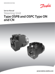
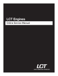
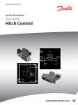
1
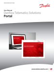
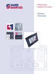
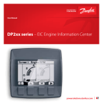
MAKING MODERN LIVING POSSIBLE
Technical Information
PLUS+1® Mobile Machine Displays
DP570 Series
powersolutions.danfoss.com
Technical Information
DP570 Series Displays
Revision history
Table of revisions
2
Date
Changed
Rev
July 2015
Vault memory, removed reference to USB port (DP570 does not have one)
FB
March 2015
Various
FA
February 2015
Converted to Danfoss layout; Ingress Protection (IP) rating updated; new drawing with
updated bracket and seal for flush mounted option
EA
December 2013 Model feature
DA
November 2013 Screw lengths and torque
CA
November 2013 Operating temperature
BA
November 2013 First edition
AA
L1328765 • Rev FB • July 2015
Technical Information
DP570 Series Displays
Contents
Literature references
DP570 reference literature............................................................................................................................................................ 4
User liability and safety statements
OEM responsibility........................................................................................................................................................................... 5
Overview
Ordering information
Inputs/outputs
DP570 Series Displays..................................................................................................................................................................... 6
PLUS+1® GUIDE............................................................................................................................................................................ 6
Linux® operating system...........................................................................................................................................................6
Features for the Linux® interface...................................................................................................................................... 6
Product naming convention........................................................................................................................................................ 7
Related products...............................................................................................................................................................................8
Inputs.................................................................................................................................................................................................... 9
Digital/Analog/CAN....................................................................................................................................................................9
Digital/Analog/4-20mA.............................................................................................................................................................9
Multifunction..............................................................................................................................................................................10
Encoder........................................................................................................................................................................................ 12
Video............................................................................................................................................................................................. 12
Outputs..............................................................................................................................................................................................13
Video power output................................................................................................................................................................ 13
Controller Area Network (CAN) specifications
CAN shield/analog inputs........................................................................................................................................................... 14
CAN communication.....................................................................................................................................................................14
Memory
Product ratings
Maintenance guidelines
Installation
NV memory...................................................................................................................................................................................... 15
FRAM Memory........................................................................................................................................................................... 15
Vault Memory.............................................................................................................................................................................15
Electrical............................................................................................................................................................................................ 16
Environmental.................................................................................................................................................................................16
Testing criteria.................................................................................................................................................................................16
LCD module .................................................................................................................................................................................... 18
Dimensions.......................................................................................................................................................................................19
Two mounting options................................................................................................................................................................ 20
Flush mounted.......................................................................................................................................................................... 20
Stand-alone on post................................................................................................................................................................ 20
Pin assignments..............................................................................................................................................................................21
Machine wiring guidelines......................................................................................................................................................... 22
Machine welding guidelines......................................................................................................................................................22
L1328765 • Rev FB • July 2015
3
Technical Information
DP570 Series Displays
Literature references
DP570 reference literature
Literature title
Literature type
Literature number
DP570 Series PLUS+1® Mobile Machine Displays
Technical Information
L1328765
DP570 Series PLUS+1® Mobile Machine Displays
Data Sheet
L1317788
PLUS+1® GUIDE Software User Manual
Operation Manual
10100824
Technical Information (TI)
A TI is comprehensive information for engineering and service personnel to reference.
Data Sheet (DS)
A DS is summarized information and parameters that are unique to a specific model.
API Specifications (API)
An API is specifications for programming variable settings.
API specifications are the definitive source of information regarding pin characteristics.
PLUS+1® GUIDE User Manual
This user operation manual (OM) details information regarding the PLUS+1® GUIDE tool set that is used to
build PLUS+1® applications. This OM covers the following broad topics:
• How to use the GUIDE graphical application development tool to create machine applications
•
•
•
•
•
How to configure module input and output parameters
How to configure module input and output parameters
How to download GUIDE applications to target PLUS+1® hardware modules
How to upload and download tuning parameters
How to use the PLUS+1® Service Tool
Latest version of technical literature
Danfoss product literature is online at: http://powersolutions.danfoss.com/literature/
4
L1328765 • Rev FB • July 2015
Technical Information
DP570 Series Displays
User liability and safety statements
OEM responsibility
The OEM of a machine or vehicle in which Danfoss products are installed has the full responsibility for all
consequences that might occur. Danfoss has no responsibility for any consequences, direct or indirect,
caused by failures or malfunctions.
• Danfoss has no responsibility for any accidents caused by incorrectly mounted or maintained
equipment.
• Danfoss does not assume any responsibility for Danfoss products being incorrectly applied or the
system being programmed in a manner that jeopardizes safety.
• All safety critical systems shall include an emergency stop to switch off the main supply voltage for
the outputs of the electronic control system. All safety critical components shall be installed in such a
way that the main supply voltage can be switched off at any time. The emergency stop must be easily
accessible to the operator.
L1328765 • Rev FB • July 2015
5
Technical Information
DP570 Series Displays
Overview
PLUS+1® Mobile Machine Displays are designed to provide flexible, expandable, powerful and cost
effective total machine management system displays for a wide variety of vehicle applications.
DP570 Series Displays
DP570 Series Displays are designed to perform in the most extreme mobile machine environments. The
latest technology with backlight provides outstanding brightness and contrast performance resulting in
an easy-to-read screen. Develop your own software and layout using the PLUS+1® GUIDE (Graphical User
Integrated Development Environment) or Linux® interface and the screen editor. A graphic library is
available for fast time-to-market.
PLUS+1® GUIDE
PLUS+1® GUIDE (Graphical User Integrated Development Environment) is a complete toolbox that
generates downloadable applications for all programmable PLUS+1® Compliant products.
A screen editor allows easy development of applications by programmers without formal software
development training. The expertise from a software engineer is not needed to find your way around in
PLUS+1® GUIDE
Linux® operating system
DP570 Series Displays contain embedded Linux® operating system software that is copyrighted software
licensed under the GPL Version 2.0 or LGPL Version 2.1.
Linux® operating system software is free software; you can redistribute it and/or modify it under the terms
of the GNU General Public License as published by the Free Software Foundation; Licenses full notice
available:
GPL Version 2.0 http://www.gnu.org/licenses/old-licenses/gpl-2.0.html
LGPL Version 2.1 http://www.gnu.org/licenses/old-licenses/lgpl-2.1.html
As an installer of Linux® operating system you will have your own obligations under the licensing
agreements, which may include among other things the obligation to include a copy of these licenses or
to include an offer of a physical copy of the source code for such software with your distributions of the
equipment. You should carefully review the licenses to determine what your obligations and options may
be for your intended use.
Anyone in receipt of this program may obtain the complete corresponding source code from Danfoss for
a period of three years after the last shipment of this product and/or spare parts by going on line at
http://www.danfoss.com or include “source code for DP570” in your written request to:
PLUS+1® Helpdesk Danfoss (US) Company
3500 Annapolis Lane North Plymouth, MN 55447 USA
Features for the Linux® interface
DP570 Series Displays hardware contain the following features for the Linux® interface:
• The 1st stage of U-Boot boot loader is installed on the system.
• There is a recovery system for reprogramming the DP570 operating system utilizing the PLUS+1®
Service Tool.
• Linux® kernel v2.6 with drivers for all standard peripherals.
• To give the developer the possibility to connect to Linux® shell it is enabled by default.
6
L1328765 • Rev FB • July 2015
Technical Information
DP570 Series Displays
Ordering information
Product naming convention
DP570 model code
A
B
C
D
E
F
G
D P 5 7 0
P200166
This is not a variant configurator.
Product configuration model code
A
B
C
D
E
F
G
Part number
DP570
01
00
00
00
00
01
11134525
DP570
01
00
00
00
01
01
11130432
DP570
01
00
00
00
00
00
11140997
DP570
01
00
00
00
01
00
11140996
A—Model name
Code
Description
DP570
PLUS+1® Mobile Machine Displays
B—Input/output options
Code
Description
01
User configurable: 1 CAN, 2 DIN/AIN, 2 DIN/AIN/4-20 mA, 2 Multi-function, 1 DOUT or 2
CAN, 2 DIN/AIN/4-20 mA, 2 Multi-function, 1 DOUT
C—Real time clock
Code
Description
00
RTC
D—Flash memory/application key
Code
Description
00
512 MB/without application key
E—Application log (vault memory)
Code
Description
00
16 MB
F—Video input options
Code
Description
00
None
01
One video input
L1328765 • Rev FB • July 2015
7
Technical Information
DP570 Series Displays
Ordering information
G—Mounting options
Code
Description
00
Post mounting
01
Panel mounting
Related products
Mating connector kit contents
Description
Part numbers
M12 5 pin male connector
11130712
DEUTSCH terminal
10100743
16 to 22 AWG crimp tool
10100744
20 AWG crimp tool
10100745
12 pin DEUTSCH WM 125 locking plug
10100741
DEUTSCH DTM06-12SA 12 pin connector kit (16 to 22
AWG)
10102025
DEUTSCH DTM06-12SA 12 pin connector kit (20 AWG)
10100944
Connection-kit DP570 with camera cable
11145163
Accessories
8
Description
Part numbers
Panel mounting kit
11140430
PLUS+1® GUIDE software application (includes a single
user licence, Service and Diagnostic tool and a Screen
Editor)
10101000
Post mounting kit
11144122
L1328765 • Rev FB • July 2015
Technical Information
DP570 Series Displays
Inputs/outputs
Inputs
DP570 Series Displays support the following pin types:
• Digital or Analog (DIN/AIN)
•
•
Digital, Analog, or 4–20 mA (DIN/AIN/4–20 mA)
Multifunction (DIN/AIN/FreqIN, Rheo, 4–20 mA)
DP570 Series Displays have input pins that support multiple functions. Pins that support multiple input
types are user-configurable using PLUS+1® GUIDE software.
Digital/Analog/CAN
Normal range multifunction input
Description
Unit
Minimum
Maximum
5.88
Range
V
0
Resolution
mV
2.14
Comment
—
—
Worst case error
mV
130
—
Input impedance
kΩ
233 ± 3
To 0 V
Input impedance with pull-down
kΩ
14.1 ± 0.2
To 0 V
Input impedance with pull-up
kΩ
14.1 ± 0.2
To 5 V
Input impedance with pull-up/down
kΩ
7.3 ± 0.1
To 2.5 V
Unit
Minimum
Maximum
37.296
High range multifunction input
Description
Range
mV
0
Resolution
mV
14.3
Comment
—
—
Worst case error
V
1.296
—
Input impedance
kΩ
110 ± 2
To 0 V
Input impedance with pull-down
kΩ
13.2 ± 0.2
To 0 V
Input impedance with pull-up
kΩ
13.2 ± 0.2
To 5 V
Input impedance with pull-up/down
kΩ
7 ± 0.1
To 2.5 V
Unit
Minimum
Maximum
5.88
Digital/Analog/4-20mA
Normal range multifunction input
Description
Comment
Range
V
0
Resolution
mV
2.14
—
—
Worst case error
mV
130
Over the full temperature
range -30º C to +60º C (-22º F
to +140º F)
Input impedance
kΩ
233 ± 3
No pull up or pull down
Input impedance with pull-down
kΩ
14.1 ± 0.2
Pull down to ground
Input impedance with pull-up
kΩ
14.1 ± 0.2
Pull up to +5 V
Input impedance with pull-up/down
kΩ
7.3 ± 0.1
Pull up to +2.5 V
L1328765 • Rev FB • July 2015
9
Technical Information
DP570 Series Displays
Inputs/outputs
Current input
Description
Unit
Minimum
Maximum
Comment
Range
mA
0
5.43
—
Resolution
μA
21
—
Worst case error
mA
1.7
Over the full temperature
range -30º C to +60º C (-22º F
to +140º F)
Input impedance
Ω
100.76 ± 0.1
—
Multifunction
Low range frequency input PPU
Description
Minimum
Typical
Maximum
Comment
Minimum discernible
voltage
0 mV
—
12.9 mV
—
404 mV
431 mV
—
Maximum discernible 377 mV
voltage
Precision
—
—
0.149 mV
—
Worst case error
—
—
27 mV
Over the full
temperature range
-30º C to +60º C (-22º
F to +140º F)
Rising voltage
threshold
0.11 V
—
0.30 V
Voltage required for
frequency input to
read high
Falling voltage
threshold
0.04 V
—
0.22 V
Voltage required for
frequency input to
read low
Input impedance
230 kΩ
233 kΩ
236 kΩ
No pull up or pull
down
Input impedance
13.9 kΩ
14.1 kΩ
14.3 kΩ
Pull up to +5V or pull
down to ground
Input impedance
7.2 kΩ
7.3 kΩ
7.4 kΩ
Pull to +2.5V
Middle range frequency input PPU
Description
Minimum
Typical
Maximum
Comment
Minimum discernible
voltage
0 mV
—
20 mV
—
5.75 V
5.88 V
—
Maximum discernible 5.62 V
voltage
10
Precision
—
—
2.14 mV
—
Worst case error
—
—
130 mV
Over the full
temperature range
-30º C to +60º C (-22º
F to +140º F)
Rising voltage
threshold
0.178 V
—
3.92 V
Voltage required for
frequency input to
read high
Falling voltage
threshold
0.84 V
—
2.79 V
Voltage required for
frequency input to
read low
Input impedance
230 kΩ
233 kΩ
236 kΩ
No pull up or pull
down
L1328765 • Rev FB • July 2015
Technical Information
DP570 Series Displays
Inputs/outputs
Middle range frequency input PPU (continued)
Description
Minimum
Typical
Maximum
Comment
Input impedance
13.9 kΩ
14.1 kΩ
14.3 kΩ
Pull up to +5V or pull
down to ground
Input impedance
7.2 kΩ
7.3 kΩ
7.4 kΩ
Pull to +2.5V
High range frequency input PPU
Description
Minimum
Typical
Maximum
Comment
Minimum discernible
voltage
0 mV
—
130 mV
—
Maximum discernible 34.704 V
voltage
36 V
37.296 V
—
Precision
—
—
14.3 mV
—
Worst case error
—
—
1.296 mV
Over the full
temperature range
-30º C to +60º C (-22º
F to +140º F)
Rising voltage
threshold
11.83 V
—
26.55 V
Voltage required for
frequency input to
read high
Falling voltage
threshold
5.61 V
—
18.89 V
Voltage required for
frequency input to
read low
Input impedance
108 kΩ
110 kΩ
112 kΩ
No pull up or pull
down
Input impedance
13.0 kΩ
13.2 kΩ
13.4 kΩ
Pull up to +5V or pull
down to ground
Input impedance
6.9 kΩ
7 kΩ
7.1 kΩ
Pull to +2.5V
Resistance input
Description
Unit
Minimum
Maximum
Comment
Range
Ω
0
10000
—
Resolution
—
—
—
—
Source current
mA
0
3.6*
—
* When configured as a resistance/rheostat/temp sensor input, the device will provide up to 3.76 mA current to an
external load which can then be measured. The equation for calculating AD counts for a given load is: AD counts =
(2338* RL / (RL + 1330)).
L1328765 • Rev FB • July 2015
11
Technical Information
DP570 Series Displays
Inputs/outputs
Rheostat inputs: AD counts and load relationship
2500
AD counts
2000
1500
1000
AD counts
500
0
0
2000
4000
6000
Load Resistance Ω
8000
10000
( )
P200167
4–20 mA input
Description
Unit
Minimum
Maximum
Comment
Range
mA
0
54.3
—
Resolution
μA
21
—
Worst case error
mA
1.7
Over the full temperature
range -30º C to +60º C (-22º F
to +140º F
Input impedance
Ω
100.76 ± 2
—
Maximum over-current voltage
V
5.43
—
W
Warning
Using these inputs can affect the accuracy of any Safety Critical closed loop control. These displays do not
have a Real Time Operating System (RTOS). Do not use these displays as the master control for any type
of safety critical control, or closed loop control system. Frequency inputs are managed by the operating
system. Accuracy can be affected by processor load. These displays should only be used for non-safety
critical related functions.
Encoder
The encoder input is only suitable for user interface functions, such as, navigating in menus and adjusting
values because there is no guarantee that all pulses are detected and the detected direction can be false.
The rate of pulses should be kept at a few tens per second to minimize the loss of detected position
changes.
The encoder function samples the A and B signals from the encoder and increments or decrements the
counter according to the phase sequence. The counter is incremented/decremented on every low to
high and high to low edge of the A signal. Some encoders with detents give a complete pulse between
detents and the counter will be incremented/decremented by two for every detent. The counter is
incremented when the A signal is the leading phase and decremented in the opposite case.
Video
There is one video input, which can accept either NTSC or PAL video signals.
12
L1328765 • Rev FB • July 2015
Technical Information
DP570 Series Displays
Inputs/outputs
Outputs
Video power output
Description
Unit
Minimum
Maximum
Typical
Comment
12V
V
11.58
12.42
12
—
Video camera power current mA
0
400
—
—
Short circuit protection
—
36
—
—
L1328765 • Rev FB • July 2015
V
13
Technical Information
DP570 Series Displays
Controller Area Network (CAN) specifications
CAN shield/analog inputs
The CAN shield pin on the unit can be used as a non-configurable analog input.
The values in the following table assumes that software compensates for errors in the analog to digital
(A/D) converter.
CAN shield
Description
Unit
Minimum
Maximum
Typical
Comment
Input impedance
—
—
—
0.68 μF + 1 Ω
—
Analog input (5 V only)
Description
Unit
Minimum
Maximum
Comment
Allowed voltage at pin
V
0
36
—
5.75
Measuring range
V
0
Resolution
mV
1.4
—
—
Worst case error
mV
±(20 + U*2%)
—
Input impedance
kΩ
233 ± 3
—
CAN communication
There are two stand-alone CAN-busses. Both CAN ports are software configurable and can be used for
PLUS+1® communication. One of them can be used either as CAN or a digital-analog input.
CAN communication
14
Description
Unit
Minimum
Maximum
Comment
Available baud rates
kBd
50
1000
The default baud rate is 250kbit.
Maximum input voltage
range
V
0
36
—
L1328765 • Rev FB • July 2015
Technical Information
DP570 Series Displays
Memory
NV memory
C
Caution
Non-volatile (NV) memory data loss is possible when the NV write cycle is not fully completed. When
downloading a new application ensure data is not being written to NV memory.
FRAM Memory
DP570 Series Displays use Ferroelectric Random Access Memory (FRAM). FRAM has a write endurance of
over 100 trillion cycles, which is ideal for datalogging. 2kB is available for application.
Vault Memory
DP570 Series Displays have 16 MB of flash vault memory (application logging memory). Application
developers use this memory to log machine event data then use the PLUS+1® Service Tool to extract the
logged data.
Accessing non-volatile or application log memory can delay the service tool scan.
L1328765 • Rev FB • July 2015
15
Technical Information
DP570 Series Displays
Product ratings
Electrical
Supply voltage
Description
Unit
Minimum
Maximum
Comment
DC supply voltage
V
9
36
With reverse polarity protection
DC supply current (circuit board only)
A
0
—
UBat = 12 V
0
—
UBat = 24 V
—
—
200 ms
Power supply interruption
(without rebooting)
W
ms
Warning
Output pins produce high voltage. High voltage can cause fire and/or electrical shock, if flammable
gasses or chemicals are present, can cause an explosion. To protect against product damage and possible
injury, do not exceed power supply voltage ratings and do not store this product where flammable
gasses or chemicals are present.
Environmental
General
Description
Units
Minimum
Maximum
Comment
Operating temperature
˚C [˚F]
-20 [-4]
+60 [+140]
—
Storage temperature
˚C [˚F]
-30 [-22]
+80 [+176]
—
Ingress Protection (IP) rating
IP67
W
With mating connector installed and
sealing plugs in unused connections.
Warning
Excessive high/low operating/storage temperatures can damage electronics. Damaged electronics can
result in performance failure. To protect against product damage and possible injury, do not operate/
store product in a environment that exceeds specified temperature ratings.
Testing criteria
Climatic
16
Condition
Rating
Cold/heat storage and operation
IEC 60068-2-1, IEC 60068-2-2
Temperature change
IEC 60068-2-14
Moisture ingress
IEC 60529
Sunlight radiation
ISO 16750-4
Temp humidity voltage
IEC 60068-2-38
L1328765 • Rev FB • July 2015
Technical Information
DP570 Series Displays
Product ratings
Mechanical
Condition
Rating
Vibration, resonance
IEC 60068-2-6
Vibration, operation
IEC 60068-2-64
Bump
IEC 60068-2-29
Shock
IEC 60068-2-27
Free fall
IEC 60068-2-32
L1328765 • Rev FB • July 2015
17
Technical Information
DP570 Series Displays
Maintenance guidelines
Opening the display's housing voids the factory warranty.
LCD module
C
Caution
Prolonged exposure to direct intense sunlight can cause premature failure of the LCD module. This risk
can be reduced by providing shading or mounting the display at an incline rather than the horizontal.
C
Caution
The protective glass will break if hit with a hard or heavy object. If the protective glass is broken, remove
the display from your machine then return the display to Danfoss to be serviced.
Clean the display's housing and protective glass with a clean, soft, damp cloth, or mild dishwashing
detergent because abrasive pads or solvents, including alcohol, benzene, and paint thinner can cause
scratching and discoloration.
18
L1328765 • Rev FB • July 2015
Technical Information
DP570 Series Displays
Installation
Dimensions
DP570 dimensions in millimeters [inches]
7.00
[0.26]
173.40 [6.83]
36.20
[1.43]
115.20 [4.54]
169.40
[6.67]
86.40
[3.40]
144.78 [5.7]
LCD
4xØ8
75.00 [2.95]
49.2 [1.94]
39.70
[1.56]
63.7 [2.51]
P200168
L1328765 • Rev FB • July 2015
19
Technical Information
DP570 Series Displays
Installation
Two mounting options
Flush mounted
DP570 panel cutout (mm [in]) and mounting kit
4X 126° ± 5°
2X 4.35 ± 0.20
[0.171 ± 0.007]
4X 120° ± 5°
162.20 ± 0.20
[ 6.386 ± 0.007]
2X 3.60 ± 0.20
[2X 0.142 ± 0.007]
1
5
2X 2.5 ± 0.5
[0.098 ± 0.020]
4
2X 6.0 ± 1.0
[2X 0.236 ± 0.039]
1.
2.
3.
4.
5.
166.20 ± 0.20
[ 6.543 ± 0.007]
2
3
6.0 [0.236]
P200174
16X R (4)
Panel seal is part of the panel mount kit
Mounting panel: 6.00 mm (0.236 in) maximum thickness
Panel bracket
M4X10 screws with lock washers (4X)
Stand-alone on post
Post mounting option (mm [in])
1
75.00 [2.95]
49.2 [1.94]
41.50 [1.63]
63.7 [2.51]
6.0 [0.236]
2
1.
2.
3.
4.
20
4X insert for M4 screw x 0.7 [0.03] thread x 11 [ 0.47] maximum depth
Post mount cover
M4X18 screws with Post mount cover lock washers (4X)
Maximum bracket thickness using screws provided with cover
L1328765 • Rev FB • July 2015
3
4
P200170
Technical Information
DP570 Series Displays
Installation
Pin assignments
DP570 pin assignments
C2
C1
P200171
Pin connectors
C2-P5
C1-P7
C1-P12
C1-P6
C1-P1
C2-P1
C2-P2
C2-P4
C2-P3
P200190
DEUTSCH
DTM06 12-pin
Phoenix M12 5-pin
C1 pin
Function
C2 pin
Function
C1-P1
Power Ground -
C2-P1
Video Power Ground
C1-P2
Power Input +
C2-P2
Video Power Supply
C1-P3
CAN0 High +
C2-P3
Video Signal Input 1
C1-P4
CAN0 Low -
C2-P4
Video Signal Ground
C1-P5
CAN Shield
C2-P5
NC
C1-P6
CAN1 High + or DIN/AIN
C1-P7
CAN1 Low – or DIN/AIN
C1-P8
DIN/AIN/4–20 mA
C1-P9
DIN/AIN/4–20 mA
C1-P10
Multi-function Input
C1-P11
Multi-function Input
C1-P12
DOUT
L1328765 • Rev FB • July 2015
21
Technical Information
DP570 Series Displays
Installation
Machine wiring guidelines
•
•
•
•
•
•
•
•
•
•
•
•
•
•
Protect wires from mechanical abuse, run wires in flexible metal or plastic conduits.
Use 85˚ C (185˚ F) wire with abrasion resistant insulation and 105˚ C (221˚ F) wire should be
considered near hot surfaces.
Use a wire size that is appropriate for the module connector.
Separate high current wires such as solenoids, lights, alternators or fuel pumps from sensor and other
noise-sensitive input wires.
Run wires along the inside of, or close to, metal machine surfaces where possible, this simulates a
shield which will minimize the effects of EMI/RFI radiation.
Do not run wires near sharp metal corners, consider running wires through a grommet when
rounding a corner.
Do not run wires near hot machine members.
Provide strain relief for all wires.
Avoid running wires near moving or vibrating components.
Avoid long, unsupported wire spans.
Ground electronic modules to a dedicated conductor of sufficient size that is connected to the
battery (-).
Power the sensors and valve drive circuits by their dedicated wired power sources and ground
returns.
Twist sensor lines about one turn every 10 cm (4 in).
Use wire harness anchors that will allow wires to float with respect to the machine rather than rigid
anchors.
C
Caution
Unused pins on mating connectors may cause intermittent product performance or premature failure.
Plug all pins on mating connectors.
Machine welding guidelines
W
Warning
High voltage from power and signal cables may cause fire or electrical shock, and cause an explosion if
flammable gasses or chemicals are present.
Disconnect all power and signal cables connected to the display before performing any electrical welding
on a machine.
The following is recommended when welding on a machine equipped with electronic components:
• Turn the engine off.
• Remove electronic components from the machine before any arc welding.
• Disconnect the negative battery cable from the battery.
• Do not use electrical components to ground the welder.
• Clamp the ground cable for the welder to the component that will be welded as close as possible to
the weld.
22
L1328765 • Rev FB • July 2015
Technical Information
DP570 Series Displays
L1328765 • Rev FB • July 2015
23
Technical Information
DP570 Series Displays
24
L1328765 • Rev FB • July 2015
Technical Information
DP570 Series Displays
L1328765 • Rev FB • July 2015
25
Products we offer:
•
•
•
•
•
•
•
•
•
•
•
•
•
•
•
•
Bent Axis Motors
Closed Circuit Axial Piston
Pumps and Motors
Displays
Electrohydraulic Power
Steering
Electrohydraulics
Danfoss Power Solutions is a global manufacturer and supplier of high-quality hydraulic and
electronic components. We specialize in providing state-of-the-art technology and solutions
that excel in the harsh operating conditions of the mobile off-highway market. Building on
our extensive applications expertise, we work closely with our customers to ensure
exceptional performance for a broad range of off-highway vehicles.
We help OEMs around the world speed up system development, reduce costs and bring
vehicles to market faster.
Danfoss – Your Strongest Partner in Mobile Hydraulics.
Hydraulic Power Steering
Go to www.powersolutions.danfoss.com for further product information.
Integrated Systems
Wherever off-highway vehicles are at work, so is Danfoss. We offer expert worldwide support
for our customers, ensuring the best possible solutions for outstanding performance. And
with an extensive network of Global Service Partners, we also provide comprehensive global
service for all of our components.
Joysticks and Control
Handles
Microcontrollers and
Software
Open Circuit Axial Piston
Pumps
Orbital Motors
Please contact the Danfoss Power Solution representative nearest you.
PLUS+1® GUIDE
Proportional Valves
Sensors
Steering
Transit Mixer Drives
Comatrol
www.comatrol.com
Schwarzmüller-Inverter
www.schwarzmuellerinverter.com
Local address:
Turolla
www.turollaocg.com
Hydro-Gear
www.hydro-gear.com
Daikin-Sauer-Danfoss
www.daikin-sauer-danfoss.com
Danfoss
Power Solutions (US) Company
2800 East 13th Street
Ames, IA 50010, USA
Phone: +1 515 239 6000
Danfoss
Power Solutions GmbH & Co. OHG
Krokamp 35
D-24539 Neumünster, Germany
Phone: +49 4321 871 0
Danfoss
Power Solutions ApS
Nordborgvej 81
DK-6430 Nordborg, Denmark
Phone: +45 7488 2222
Danfoss
Power Solutions Trading
(Shanghai) Co., Ltd.
Building #22, No. 1000 Jin Hai Rd
Jin Qiao, Pudong New District
Shanghai, China 201206
Phone: +86 21 3418 5200
Danfoss can accept no responsibility for possible errors in catalogues, brochures and other printed material. Danfoss reserves the right to alter its products without notice. This also applies to
products already on order provided that such alterations can be made without changes being necessary in specifications already agreed.
All trademarks in this material are property of the respective companies. Danfoss and the Danfoss logotype are trademarks of Danfoss A/S. All rights reserved.
L1328765 • Rev FB • July 2015
www.danfoss.com
© Danfoss A/S, 2015