1
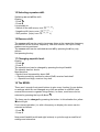
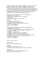
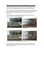
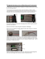
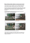
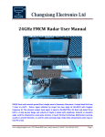
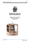
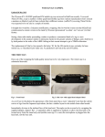
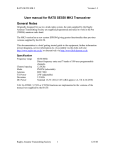
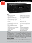
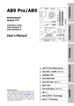
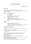
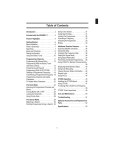
User manual Ascom SE550 Transceiver Document Revision history Revision Date Changes nd Initial release th Typographical changes and better description of operation. Keypad selection icons amended Changes to Transceiver operation text, addition of tone squelch, and tone burst information. Better info on memories and battery backup added 1.5 2 August 2004 1.6 6 August 2004 1.7 14 August 2004 1.8 18 August 2004 2.0 24 August 2004 2.1 25 August 2004 2.2 29 August 2004 2.3 8 September 2004 2.4 9 October 2004 2.5 8 April 2005 2.6 27 November 2006 2.7 24 June 2007 2.8 6 August 2007 th th th th th th th th th th th Author: Andy G0BEQ Re-collated document. New front page, document history page unhidden and new page on battery backup added. References to 5tvo removed. Backup battery part number and assembly info added. Web site reference link changed to rrguk.org. Front page referenced to RRG Battery backup DIY mods appended to document Changed references to IF options in hardware sub-menu, removed Dutch text in Ch9 Minor changes to button definitions Page4, Squelch definition Page9 Minor text mods and changes to the use of the telephone button. Link to French web-site added. Note about erroneous power-up settings added. Changes to 18-Menu - To assist in understanding how the menu command operates. Thanks to Andy GJ7JHF Web-site reference for RRG changed Update to website links Updates to battery backup pages User manual Ascom SE550 Transceiver This document is intended as a brief getting started guide to the radio. Further information (circuit diagrams, service information etc) is available on the following web site – http://www.g0beq.fsnet.co.uk/ascom/ascom.htm and from other references found to the rear of this guide. Information within this document has been compiled from several sources in an effort to satisfy the needs of a user in understanding the operation of the radio when fitted with MK3 software. It is provided on a best endeavours basis, with no guarantee that it is always correct. Transceiver Specification The ASCOM SE550 was original used in a trunked radio system and has been modified to work in the 4m (70MHz) amateur radio band. Frequency Range : 70 – 88 MHz Channel Spacing : 5 / 6.25 / 10 /12.5 / 15 / 18.75 / 20 / 25 kHz steps Modulation mode : FM / PM Antenna : BNC 50Ω TX Power : Adjustable to 25W max Deviation : 2.5kHz DC Power : Nominal 13.2V (10.8 – 15.6V) (RX approx 1A, TX 6.5A/25W) Amateur radio Eprom software version – MK3 Transceiver Operation · Connect power, loudspeaker and microphone · Connect the microphone to the lower front panel receptacle · Ensure that a jumper is fitted to the lower pair of pins in the upper front panel receptacle (the rig will not power up without this jumper) or that a “code plug” is fitted in this slot. Please note: 1/ In normal operation the radio does get quite hot. 2/ The display will automatically adjust the display brilliance to match ambient light levels. A sensor for this is located to the top right edge of the display area. 3/ Most radio’s will be supplied without battery backup for memory retention as the original use was in a trunked system and permanently connected to a vehicle 12v supply. Further information can be found at the rear of this document. As a result the radio may power up with erroneous power/volume/frequency settings. Keypad overview: To turn on/off the radio, momentarily depress the IO button. If the button is held pressed in too long the radio will switch off. Keys: Function: + / - To adjust volume level ← Squelch open/close on RX, 1750HZ tone on TX x w z y (four buttons) allow up/down of Mhz/Khz frequency in VFO mode 0 1 2 3 4 5 6 7 8 9 To enter a Channel, frequency or number. * Scan # Reverse shift ⌂ Go to call-channel S Switch between VFO and Memory / clear last command ▲Tone squelch On/Off(DTSS / 5-tone) Confirm action/button sequence / erase last entry 2 Choose second function of next key Second function Keys: 1 Change transmitter power 2 Change squelch level 3 Choose CTCSS tone (TQ) 4 Activate MENU 5 Activate status menu 6 Show name of memory channel 8 Choose channel spacing (raster) * Don’t scan this memory channel 0 Call with 5-Tone # Shift + / - / none ▲Choose tone-squelch code ⌂ Delete/store call channel S Delete/store memory channel After switching on the transceiver, the selected frequency or channel will be shown at the upper line of the display. After receiving a 5 tone code, the code will be printed at the second line of the display. The selected memory bank is indicated at the right of the second line. To use the second function of the keys, press the 2 button. The text ‘Choose function’ will appear on the second line of the display. Now the second function of the next key will be activated. To go back to the normal situation, press 2 again or use the button. 1 Choose frequency. The transceiver has three frequency modes, with the S button can be changed from VCO to Memory. The third mode is the call channel, this one can be selected with the ⌂ key. - VCO mode At VCO mode all frequencies at the chosen channel spacing can be entered with the keypad. For the frequency 70.012.500, by a channel space of 12,5kHz, you have to enter ‘7001’: - Memory mode The Ascom has the possibility to store 100 memory channels in one memory bank, it has 7 memory banks. These channels are available in the memory mode. In this mode, each channel can have its own name of max. 23 characters. If the selected channel number is empty, the Ascom will generate an error beep and ignores the selected channel. Please note memory storage is dependant on power being available to support memory storage, although some radio’s may be fitted with internal memory backup battery. Details of the location of this battery may be found later. - Call channel mode If the call channel is programmed, this frequency can be selected very quickly. The advantage of the call channel is, it can be selected by only pressing the ⌂ key. 2 Choose CTCSS tone. (if option available on radio) Some transceivers and repeaters use CTCSS, only transmitters which send a low frequency tone of 67 - 250Hz will be heard. All others transmissions may be ignored. The frequency of this low frequency tone can be selected as follows: Display: - Press 2 - Press 3 The lowest frequency is 67Hz en the highest 250.3Hz, between those values. 3 Tone squelch (Selcall). (if option available on radio) The squelch can be closed until receiving a selected 5-tone code, and the transmitter can send a selectable 5-tone code for the opposite station. Activate: The tone squelch can be activated by the ▲key, for the receiver the yellow key will light on and for the transmitter, a T will appear in the display. Selecting code: This code can be selected as follows: Display: - Press 2 - Press ▲ Now select the tonecode for the receiver. The code must be entered with the keys 0-9, when the number are flashing, its a DTMF tone. - Press 2 Now select the tonecode for the receiver 3a Tone Burst / DTMF tones. A tone burst will be generated by pressing the squelch-open key while transmitting. DTMF tones may be entered directly on the keypad whilst transmitting. 4 Chosen channel step space. Display: - Press 2 - Press 8 The channel step spacing can be changed by pressing the keys 0 en #. 5 Storing memory channels. It is possible to store 100 channels in each bank. Store channels as follows: Display: - Go to the VCO mode (key S). (70.***.*** ) - Choose the frequency and, if necessary, select SHIFT and CTCSS. - Press . 2 ( Second function ) - Press S (Store in: xx) - Choose a number to store the channel. When an arrow appears, and the chosen number is already used, the old values will be overwritten - Press 2 - If you want, give a name for this channel (Name: ) x w to move to next or previous character. Letters are accessible as per a telephone keypad. (abc -2, def -3, ghi -4, jkl – 5, mno – 6, pqrs – 7, tuv – 8, wxyz – 9) - Press again 2 to store. 6 Memory banks. The Ascom has 7 memory banks, each memory bank has its own 100 memory channels. The advantage is that only channels in the selected bank will be scanned. Select a higher bank: - Press R If the selected bank contains only empty memory channels, the VCO mode will be activated, otherwise, the Ascom switches over to the memory channels. 7 Storing the call channel. It may be easy to activate the most used frequency by only pressing the button. This frequency has to be programmed as follows: Display: - Go to the VCO mode (key S). (70.***.*** ) - Choose the frequency and, if necessary select SHIFT and CTCSS. - Press . 2 (Choose Function ) - Press . ⌂ - Press . 2 - If you want, give the call channel a name (Name: ) - Press again. 2 8 Enable channel-name. Every memory channel can have its own name, the displaying of the name can be enabled or disabled as follows: Display: - Press 2 ( Choose Function ) - Press 6 9 Erase a memory channel. Display: - Go to the memory mode (key S) - Enter the channel to be erased - Press 2 (Choose Function ) - Press S - Press 2 10 Erase the call channel. Display: - Go to the call channel (key ⌂ ) - Press 2 - Press ⌂ - Press 2 11 Entering text. Text has to be entered the same way as entering text on a phone. Entering the letters A, B or the C, has to be done by pressing the 2 several times. The button is for erasing a character, the remaining characters are shifting back, just like the DEL key in a word processor. The “remove from column” ()) key is used to insert a space. With the arrow-keys up and down are used to step through the character group of the selected key. The cursor has to be moved by pressing the arrow-keys left and right. 12 Scanning. It’s possible to scan in VFO mode and Memory mode: Scanning all frequencies: - Go to VFO mode with the key S - Press * Scanning the memory channels: - Go to the memory mode with the key S - Press * Press any other key to stop scanning. The red R light indicates scanning. If the transceiver has found a signal, the scanning can be continued by pressing * again. 13 Lock out memory channels. Scanning the memory channels will scan all channels in the selected bank. With the lockout function, each channel can be disabled for scanning. It’s possible to skip several memory channels while scanning. Display: - Go to the memory (key S) - Choose the channel - Press 2 - Press * The red R light indicates the lock out function. To undo this, repeat this. 14 Transmitter power. The output power of the transmitter depends on the following conditions: - The value selected in software - External power control potentiometer - VSWR - Temperature Changing power setting in software: Display: - Press 2 - Press 1 The power can be changed by pressing the buttons 0 and #. Acknowledge with any other key. 15 Selecting repeater-shift. Switching on and off the shift: Display: - Press 2 - Press # It is possible to: - Switch off the shift (display reads 70.***.*** ) - Negative shift (display reads 70.***.*** - ) - Shift positive (display reads 70.***.*** + ) 16 Reverse shift. The reverse shift can be used to temporary listen at the transmitter frequency and transmit at the receiver frequency. With this function, the input of relay stations can be monitored. The reverse shift can be switched on and off by pressing the # key only, without first pressing the key. 17 Changing squelch level. Display: - Press 2 - Press 2 The squelch level can be changed by pressing the keys 0 and #. The squelch has four levels: Most sensitive - Squelch level increased by about 5dB - - Receiver sensitivity reduced by about 20dB, receiver feels deaf! - - - Squelch level high, receiver very deaf. 18 The MENU. There aren’t enough front panel buttons to give every function it’s own button, so settings which are not changed very often are placed in a MENU (with several sub-menus to organise things better). In menu, most items can be selected by pressing the keys 0, # and 2. The items can be changed by pressing the button. In this situation the yellow led will light. From normal operation (i.e. with a frequency on display) the menu can be selected as follows: - Press 2 - Press 4 Now press 0 and # (as left and right buttons) to cycle through a small list of settings and submenus. Press 2 to change an item or to enter a submenu. If the item has a limited number of settings (such as ON/OFF), then2 will toggle between them. Otherwise a yellow indicator will light to signify a further setting mode. - in this case use 0 and # to lower or raise a setting (or key in a number in the case of numerical settings such as repeater shift) and then press 2 again to exit the setting mode and return to list of items (yellow light goes off). To exit the MENU or any submenu press any otherwise unused key - such as numerical keys 1 to 9 - this will take you back up a level. Example : Turn on/off keypad beeps (from normal operation) - press 2 to choose a function... - press 4 to choose the MENU function - MENU will appear top right. - If necessary press 2 until "Audio submenu -->" appears - press 2 to enter the submenu - press # until "Key Beep" setting appears - press 2 to change the setting ON/OFF as required - press 5 to exit the submenu - press 5 to exit the MENU Example : Change keypad beep volume (from normal operation) - press 2 to choose a function... - press 4 to choose the MENU function - MENU will appear top right. - If necessary press 2 until "Audio submenu -->" appears - press 2 to enter the submenu - press # until "Key Beep Volume" setting appears - press 2 to enter setting mode (yellow LED will light)... - press 0 or # one or more times to lower/raise the volume as required - press 2 to exit the setting mode (yellow LED will go out) - press 5 to exit the submenu - press 5 to exit the MENU These are the menu items: - Shift ****** kHz This is the value of the repeater shift. - TX Limit Transmission timeout after xxx seconds TX-time limiter. When entering zero, the TX STOP is disabled. - Scan mode This is how the Ascom acts when receiving a signal Wait for silence / Scan & stop / Wait - Audio Submenu - RX mode FM / PM This is a filter in the LF-circuit PM / FM modulation - TX mode FM / PM This is a filter in the LF-circuit PM / FM modulation - Datakiller ON/OFF Data killer on / off. - Key Beep Keypad beep on / off. - Key Beep Volume Keypad beep volume. - Roger Beep Transmits a beeptone before switching off TX - DTMF tones *** mS This is the length of the DTMF tones. - ZVEI tones *** mS This is the length of the ZVEI tones. - Call Tutor Submenu (all a bit vague this !) - Call Tutor On/Off/Hold TX This is to switch on and off the 5-tone answering. - Callsign: Enter an Alpha-numeric code - After TX: Enter a time after TX in seconds - Every: Enter a repeat time in seconds - User Submenu - My number *** (if option available on radio) This is the personal (my number) code of the user. The Ascom gives alarm when receiving this code. - Step xxx This is the acceleration of the up- and down key. The longer this key is pressed, the faster the the steps will be. - Keys: When holding a key for a while, they can be repeated (Repeat / Once only) - Settings: clear memory All settings can be reset, using default settings. - Hardware Submenu - IF 21.855MHz / 20.945MHz This is the first IF and can be used for unwanted (image) signal rejection. LP filters >20kHz raster This is the width of the LP filter for the receiver. - Status Diagnose When the red error light burns, the problem can be shown here by pressing the key. - Common Submenu Options in here are reflections of settings available via other direct key sequences detailed earlier 19 Select call. It is possible to store 10 names with corresponding tone code. These tonecodes can be transmitted with select call. Select call: Display: - Press 2 - Press 0 - Choose the name to call. - Press # Changing and storing names or codes: Display: - Press 2 - Press 0 - Choose the name or code to change. - Press (Name: ) - Enter or change the name - Press 2 to acknowledge - Enter or change the (numeric) code. - Press 2 to acknowledge The 2 key is used to acknowledge, any other key to cancel. Connections Power & Loudspeaker (15 way D on back panel) N.B. An adaptor with power and loudspeaker connections is normally supplied. 1 +VE power 2 +VE power 3 Loudspeaker +ve 4Ω 4 5 6 AF Earpiece 600Ω 7 GROUND 8 GROUND 9 Ground for 10dB RF Power reduction (can fit pot for variable power) (22K = 10W) 10 Loudspeaker -ve 4Ω 11 PTT active=L – ground to TX. (approx 0,5mA at 5V) 12 AF in 600mv 13 14 +9V out 15 Microphone 100mv Code Plug Socket (upper front panel) 12 34 56 7 8 (Jumper pin 7 to pin 8) A code plug (EEPROM) is not required for the units supplied by the Ridgeway Repeater Group, but the rig will not power up without a jumper between the bottom two pins of this socket (7 & 8). It is intended that a code plug or link will be supplied where possible. Microphone (lower front panel) Microphone B~ 1mV 1 2 Not used +9V 3 4 PTT Earphone 5 6 Microphone Ground General Ground 7 8 Earphone Ground Reference Information On the Continent the ASCOM SE550 is often known as a “Condor 3000”. The EPROM software used to program the units was supplied by Stephen Tompsett of the Rugby Amateur Transmitting Society. (RATS) Useful Web links: www.blob.demon.co.uk - Stephen Tompsett website http://home-1.tiscali.nl/~moertje/condor3000/condor.htm - There is a lot of useful information on this site, but it is in Dutch! An alternative set of software (not free!) with additional functionality can be found at: http://home.planet.nl/~kolle049/condor.html Once again this page is in Dutch! http://f5jtz.free.fr/pjacquet/radiotel-ascom.htm - A large amount of information, albeit in French. 70MHz [4m] UK Band Plan 70.000MHz to 70.030MHz Beacons. 70.030MHz Personal Beacons 70.030MHz to 70.250MHz SSB/CW. 70.150MHz Meteor Scatter calling. 70.185MHz Cross-Band activity centre. 70.200MHz SSB/CW calling. 70.250MHz to 70.300MHz All Modes. 70.260MHz AM/FM Calling. 70.300MHz to 70.500MHz Channelised Operation [12.5kHz Channels] FM Calling Channel : 70.4500MHz. FM Simplex – used by GB2RS : 70.4250MHz. Emergency Communications Priority : 70.3500MHz 70.3750MHz 70.4000MHz. RTTY/Fax Calling/Working : 70.3000MHz. Digital Modes : 70.3125MHz 70.3250MHz 70.3375MHz 70.3625MHz 70.3875MHz 70.4125MHz 70.4375MHz 70.4625MHz 70.4875MHz. Power Limit : 22dBW PEP Permitted Modes : Morse, Telephony, RTTY, Data, FAX, SSTV. Memory Backup battery details (on microprocessor board) These pages have been put together to assist in identifying/modifying the Ascom radio with regards to battery backup used for memory retention. Only a few of the radio’s are already fitted with a lithium battery already inside, however as the radio was previously used in a trunked radio system, most do not. It is possible to install a battery if you are confident in soldering / electronics. The following pictures, show the radio’s microprocessor board with and without the factory installed battery backup:- The above illustrates a radio without memory backup battery fitted The above illustrates a radio with memory backup battery fitted A lithium battery, Sonneshine 3.6v SL-340, or similar, must be fitted in the radio to ensure that the data stays in the RAM when the main 12v supply voltage is switched off. DIY approach (assumes you are confident with yourself in electronics) An alternative, but just as effective installation of battery backup can be made by the following method:To access the microprocessor board, where the battery is fitted, entails removing the front control panel (two allen screws) and the microprocessor assembly will then be found behind the panel (four cross-head screws). Flip up the handle and remove the code plug if one is fitted to gain access to the allen screw behind. Remove both Allen screws along with microphone cable/plug. Remove the front panel by hinging away from the radio (“hinge” is to the left side of front panel) Obtain a vertical mount 3volt CR2032 coin cell lithium battery or similar and solder 60mm of wires as shown above. Insulate the whole construction (keep it as thin as possible) [it’s possible to use an ordinary CR2032 as well – just a little harder to solder the wires] Identify the Battery connections on the radio, and also the solder bridge that will need to be bridged with solder as shown in the photo above. Solder the battery wires as shown above. Ensure that the –ve battery terminal is connected so as to bridge the solder bridge as without the bridge being in place, battery backup is not enabled. Locate the insulated battery in the front of the chassis, ensuring it is not in the way of the front panel upon re-assembly as shown above. If this is too thick upon re-assembly an alternative location is sandwiched between the front panel circuit boards with the wires tucked around the edge. Finally re-fit the front panel, microphone, allen screws, and code plug (if used) and test the radio to ensure battery backup works. If the above is successful, you now have a working memory backup for your Ascom radio. The life of the battery is not known at this stage, but should provide several months backup as a minimum, assuming the radio is regularly used as well. [To date I’ve had one going for 2+3/4 years – Andy G0BEQ Aug 2007]