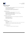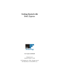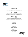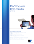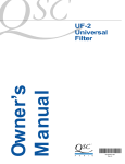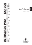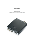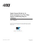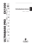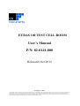
1
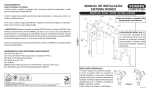
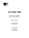
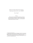
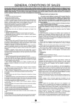
ETDAS 100 TEST CELL ROOM User’s Manual P/N: 82-0141-000 Released, Oct 2012 Copyright 2009 THIS DOCUMENT AND THE TECHNICAL DATA DISCLOSED ARE PROPRIETARY TO VTI INSTRUMENTS CORP. (HENCEFORTH REFERED TO AS VTI) AND SHALL NOT, WITHOUT EXPRESS WRITTEN PERMISSION OF VTI, BE USED, RELEASED, OR DISCLOSED IN WHOLE OR PART OR USED TO SOLICIT QUOTATIONS FROM A COMPETITIVE SOURCE OR BE USED FOR MANUFACTURE BY ANYONE OTHER THAN VTI. THE INFORMATION HERE ON DISCLOSED HAS BEEN DEVELOPED AT PRIVATE EXPENSE AND MAY ONLY BE USED FOR PURPOSES OF ENGINEERING EVALUATION AND FOR INCORPORATION INTO TECHNICAL DOCUMENTS WHICH SPECIFY PROCUREMENT FROM VTI. User Manual ETDAS 100 Test Cell Room P/N: 82-0141-000 TABLE OF CONTENTS Certification .......................................................................................................................................................... 3 Warranty ............................................................................................................................................................... 3 Limitation of Warranty ......................................................................................................................................... 3 Restricted Rights Legend ...................................................................................................................................... 3 Declaration of Conformity .................................................................................................................................... 3 GENERAL SAFETY INSTRUCTIONS ............................................................................................................................. 4 Terms and Symbols .............................................................................................................................................. 4 Warnings............................................................................................................................................................... 4 1. INTRODUCTION ......................................................................................................................................................... 6 1.1 Scope of the Document .......................................................................................................................... 6 1.2 Reference Documents ............................................................................................................................ 6 1.3 System Overview ................................................................................................................................... 6 1.4 Isometric View....................................................................................................................................... 8 2. INTERNAL PARTS & ACCESSORIES ................................................................................................................................. 9 2.1 Connector Panel ................................................................................................................................... 11 2.2 CT 100C Chassis: ....................................................................................................................................... 12 2.3 EX 1200-1262 LXI mainframe ........................................................................................................... 12 3. PART LIST & WIRING DIAGRAM .................................................................................................................................. 12 4. GETTING STARTED ................................................................................................................................................... 13 4.1. Visual checks: ...................................................................................................................................... 13 4.2. Before Power on: ................................................................................................................................. 13 4.3. Powering on the system: ...................................................................................................................... 13 4.4. Operation: ............................................................................................................................................ 13 4.5. System Maintenance: ........................................................................................................................... 13 ETDAS 100 Test Cell Room 2 User Manual ETDAS 100 Test Cell Room P/N: 82-0141-000 CERTIFICATION VTI Instruments Corp. (VTI) certifies that this product met its published specifications at the time of shipment from the factory. VTI further certifies that its calibration measurements are traceable to the United States National Institute of Standards and Technology (formerly National Bureau of Standards), to the extent allowed by that organization’s calibration facility, and to the calibration facilities of other International Standards Organization members. Note that the contents of this document are subject to change without notice. WARRANTY The product referred to herein is warranted against defects in material and workmanship for a period of one year from the receipt date of the product at customer’s facility. The sole and exclusive remedy for breach of any warranty concerning these goods shall be repair or replacement of defective parts, or a refund of the purchase price, to be determined at the option of VTI. For warranty service or repair, this product must be returned to a VTI Instruments authorized service center. The product shall be shipped prepaid to VTI and VTI shall prepay all returns of the product to the buyer. However, the buyer shall pay all shipping charges, duties, and taxes for products returned to VTI from another country. VTI warrants that its software and firmware designated by VTI for use with a product will execute its programming when properly installed on that product. VTI does not however warrant that the operation of the product, or software, or firmware will be uninterrupted or error free. LIMITATION OF WARRANTY The warranty shall not apply to defects resulting from improper or inadequate maintenance by the buyer, buyersupplied products or interfacing, unauthorized modification or misuse, operation outside the environmental specifications for the product, or improper site preparation or maintenance. VTI Instruments Corp. shall not be liable for injury to property other than the goods themselves. Other than the limited warranty stated above, VTI Instruments Corp. makes no other warranties, express, or implied, with respect to the quality of product beyond the description of the goods on the face of the contract. VTI specifically disclaims the implied warranties of merchantability and fitness for a particular purpose. RESTRICTED RIGHTS LEGEND Use, duplication, or disclosure by the Government is subject to restrictions as set forth in subdivision (b)(3)(ii) of the Rights in Technical Data and Computer Software clause in DFARS 252.227-7013. DECLARATION OF CONFORMITY The declaration of conformity for the EX1200 Series Mainframe applies to all of its available plug-in modules and options. For specifics, refer to the EX1200 Series Mainframe User’s Manual. VTI Instruments Corp. 2031 Main Street Irvine, CA 92614-6509 U.S.A. ETDAS 100 Test Cell Room 3 User Manual ETDAS 100 Test Cell Room P/N: 82-0141-000 GENERAL SAFETY INSTRUCTIONS Review the following safety precautions to avoid bodily injury and/or damage to the product. These precautions must be observed during all phases of operation or service of this product. Failure to comply with these precautions, or with specific warnings elsewhere in this manual, violates safety standards of design, manufacture, and intended use of the product. Service should only be performed by qualified personnel. TERMS AND SYMBOLS These terms may appear in this manual: WARNING Indicates that a procedure or condition may cause bodily injury or death. CAUTION Indicates that a procedure or condition could possibly cause damage to equipment or loss of data. These symbols may appear on the product: ATTENTION - Important safety instructions Frame or chassis ground Indicates that the product was manufactured after August 13, 2005. This mark is placed in accordance with EN 50419, Marking of electrical and electronic equipment in accordance with Article 11(2) of Directive 2002/96/EC (WEEE). End-of-life product can be returned to VTI by obtaining an RMA number. Fees for take_2ack and recycling will apply if not prohibited by national law. WARNINGS Follow these precautions to avoid injury or damage to the product: Use Proper Power Cord To avoid hazard, only use the power cord specified for this product. Use Proper Power Source To avoid electrical overload, electric shock, or fire hazard, do not use a power source that applies other than the specified voltage. ETDAS 100 Test Cell Room 4 User Manual ETDAS 100 Test Cell Room P/N: 82-0141-000 WARNINGS (CONT.) Avoid Electric Shock To avoid electric shock or fire hazard, do not operate this product with the covers removed. Do not connect or disconnect any cable, probes, test leads, etc. while they are connected to a voltage source. Remove all power and unplug unit before performing any service. Service should only be performed by qualified personnel. Ground the Product This product is grounded through the grounding conductor of the power cord. To avoid electric shock, the grounding conductor must be connected to earth ground. Operating Conditions To avoid injury, electric shock or fire hazard: Do not operate in wet or damp conditions. Do not operate in an explosive atmosphere. Operate or store only in specified temperature range. Provide proper clearance for product ventilation to prevent overheating. DO NOT operate if any damage to this product is suspected. Product should be inspected or serviced only by qualified personnel. Improper Use The operator of this instrument is advised that if the equipment is used in a manner not specified in this manual, the protection provided by the equipment may be impaired. Conformity is checked by inspection. ETDAS 100 Test Cell Room 5 User Manual ETDAS 100 Test Cell Room P/N: 82-0141-000 1. INTRODUCTION 1.1 SCOPE OF THE DOCUMENT This user manual is intended for the use of Temp Scanner by Hindustan Aeronautics Limited (HAL). This manual outlines necessary information which shall be used by the operator of this system. This manual is supported by other technical documents and data sheets as mentioned in Para 1.2. 1.2 REFERENCE DOCUMENTS Sl No 1.3 Ref Document P/N Usage 1 Technical Specification 93-0084-001 Document (TSD) BOM, system configuration and wire list, mechanical details of enclosure. 2 User Manual of EX1262 Technical and operating details of EX1262 LXI chassis and 61/2 Digit DMM. 3 User Manual of EX1200- 82-127-001 3048S Technical and operating details of multiplexer module EX1200-3068S. 4 User Manual of EX 1200- 82-127-001 5002 User manual of Ex 1200 series switch cards. 5 User Manual of CT 100C 82-0102-000 User manual of SIX-SLOT VXI bus chassis. 6 User Manual of EX 2500 82-0115-000 User manual of LXI-VXI Gigabit Ethernet Slot 0 Interface. 7 User Manual of SMP 7500 82-0058-000 User manual of Digital I/O module. 8 User Manual of VT1415A 82-0074-000 User manual of algorithmic Closed loop Controller. 9 User Manual of VT1435 82-0010-000 User manual of 4-/8-Channel 102.4kSa/s Digitizer with IEPE current source and TEDS support 10 User Manual of AXI429 N/A User manual of hardware manual. 82-0127-000 Open Collector AXI429-8/16/32 SYSTEM OVERVIEW ETDAS 100 Test Cell room configurations made with CT 100C system (6 slot, VXI mainframe with five Cards) and EX1262 system (2 slot LXI mainframe with two cards). Cards details are as follows, 1. CT 100C (SIX Slot VXI bus chassis) ETDAS 100 Test Cell Room 6 User Manual ETDAS 100 Test Cell Room P/N: 82-0141-000 The CT-100C portable C-size VXI bus mainframe provides cost effective test situation in a small footprint. The CT- 100C Chassis contains six slot in the card cage five of which are available for use by VXI bus compatible instruments. The six slot in the card cage (slot 0) is typically dedicated to the VXI bus resource manager. 2. EX 2500 (LXI-VXI Gigabit Ethernet Slot 0 Interface) VTI instruments EX2500 is the industry’s first gigabit, LAN based VXI slot 0 interface , which merges Ethernet’s robust architecture and wide spread infrastructure , the first emerging LXI standard for instrumentation, and the popular VXI bus platform . providing a solution that recognizes a system designer’s need to remain compatible with legacy systems and desire to adopt new technologies. 3. SMP 7500 (Open Collector Digital I/O module) The SMP 7500 is a high performance I/O module that has been designed for high data throughput and flexibility of configuration . The instrument uses direct register access for very high speed data input and retrieval. 4. VT1415A (Algorithmic Closed loop Controller) VT1415A is an algorithmic process loop controller. It can provide as many as 32 single –input /single out put control loop in a single VXI bus module. The VT1415A provides advance d data acquisition capability which includes on board signal conditioning and engineering unit conversion. 5. VT1435 (4-/8-Channel 102.4kSa/s Digitizer with IEPE current source and TEDS support) VTI technologies VT1432B,VT1435,and VT1436 are C-size single slot ,register based VXI modules that includes digital processing ,transducer signal conditioning ,alias protection ,digitization and high speed measurement computation. VT1435 and VT1436 modules have integrated electronics piezoelectric current sources as well as optional transducer electronic data sheet support. 6. AXI429 (ARINC 429-8/16/32 Channel) The AXI 429 provides eight, sixteen or thirty- two fully configurable ARINC 429 channel on a single slot VXI bus module. Whereby the eight or sixteen channel configuration is an assembly variant of the AXI429 thirty-two channel board. Each channel can be individually configured by software as a transmit or receive channel with different front panel connector outputs and inputs. 7. EX1200-1262 (EX1200 Series; 1/2 rack 1U LXI Instrument, 2 Slot with 6.5 Digit DMM) The EX1200 series is the highest density switch and I/O instrument on the market today with the capacity to house up to 576 channels of multiplexing and the ability to mix low-level, power, and RF switch modules in a single 1U mainframe. This scalable family of products is designed to leverage capital investments in one common hardware and software platform that can be used in development, manufacturing, and field service with 3U mainframes that can be integrated into large-scale ATE applications. Mix and match a variety of modules to build a comprehensive ETDAS 100 Test Cell Room 7 User Manual ETDAS 100 Test Cell Room P/N: 82-0141-000 signal switching subsystem that can be supplemented with precision analog and digital I/O modules. 8. EX1200-3048S (4 8 – Channel FET Multiplexer) The EX1200-3048S is a high-density FET multiplexer module designed for scanning of multiple points to a common bus in either 2- or 4-wire configurations. Scanning can be done either synchronously with the eX1200 DMM scan function or asynchronously as a system switch to other devices through the hardware trigger bus or LXI LAN messages. 9. EX 1200-5002 . The EX1200-5002 is a high-density general purpose 2A switch modules designed for systems where individual relays can be used to route signals to/from the units under test (UUT) or combined externally to form user-defined configurations. These relays are commonly used to create complex signal distribution networks that can be reconfigured through different wiring in test adapters. 1.4 ISOMETRIC VIEW FIGURE 1: ISOMETRIC VIEW ETDAS 100 Test Cell Room 8 User Manual ETDAS 100 Test Cell Room P/N: 82-0141-000 2. INTERNAL PARTS & ACCESSORIES LEGENDS: 1- Door Switch 2- Power Control Panel 3- CT 100C 4- Terminal Block 5- Location for EX 1262 FIGURE 2: SYSTEM INTERNAL VIEW ETDAS 100 Test Cell Room 9 User Manual ETDAS 100 Test Cell Room P/N: 82-0141-000 FIGURE 3: SYSTEM SIDE VIEW ETDAS 100 Test Cell Room 10 User Manual ETDAS 100 Test Cell Room P/N: 82-0141-000 2.1 CONNECTOR PANEL 1 2 3 5 4 6 LEGENDS: 1- Ethernet input connector 2- BNC Connector 3- Circular Connector for I/O signals 4- I/O signal name plate 5- AC power I/P connector 6- MCB FIGURE 4. PANEL VIEW ETDAS 100 Test Cell Room 11 User Manual ETDAS 100 Test Cell Room P/N: 82-0141-000 2.2 CT 100C CHASSIS: FIGURE 5: CT 100C CHASSIS 2.3 EX 1200-1262 LXI MAINFRAME FIGURE 6: EX 1200-1262 LXI MAINFRAME 3. PART LIST & WIRING DIAGRAM Parts list and wire list for this configuration are listed in Technical Specification Documents as mentioned in reference documents. Please refer TSD for more details. ETDAS 100 Test Cell Room 12 User Manual ETDAS 100 Test Cell Room P/N: 82-0141-000 4. GETTING STARTED 4.1.VISUAL CHECKS: Check all the sub modules are properly inserted in the rack, as per the assembly drawing. Check for connectors for any pin damage. Check for proper cable connection. There should not be any foreign object within system enclosure. Check the filter for cleanliness, if required clean the filter. 4.2.BEFORE POWER ON: Check the due date of instrument calibration for accuracy of results. Check for proper power supply grounding. Measure the power connector resistance ( Pin to Pin should be 20M ohm) Make sure that 230VAC mains is available. Make sure that the MCB is in ON condition. 4.3.POWERING ON THE SYSTEM: Connect 230VAC to enclosure power inlet with using Bals power mating connector. Turn the power switch ON. Make sure power indicator is lit. Check whether fan is working. 4.4.OPERATION: Connect Ethernet cable to PC. Turn on the PC. Run the Agilent Connection Expert and Exlab software and check all the cards are detecting. User can configure and view channels as mentioned in software manuals. 4.5.SYSTEM MAINTENANCE: As mentioned in user manuals of the respective instruments. ETDAS 100 Test Cell Room 13