1
PARxCH User’s Guide
Manual Release 01/30/07
Copyright (c), Symmetric Research, 2007
Web: www.symres.com
WARRANTY
LIMITED WARRANTY
WHAT IS COVERED
Symmetric Research warrants its PARxCH product will be free from defects in
workmanship and materials for one year from the date of original purchase.
WHAT SR WILL DO
Symmetric Research will repair or replace defective PARxCH systems covered under this
warranty at no cost to the customer other than shipping. The customer is responsible for
shipping to SR manufacturing facilities.
WHAT IS NOT COVERED
Symmetric Research does not warrant the PARxCH product for use with customer provided
power supplies or analog input voltages outside the range of values listed in this manual.
Incorrectly connecting power or analog inputs may permanently damage the system.
Furthermore, PARxCH systems that have been customer modified, including but not limited
to changes to the analog input voltage range circuitry, are also not covered under this
warranty.
Symmetric Research will at its discretion determine when any returned equipment
has been run from incorrect power supplies, incorrect analog inputs, or without
AGND connected, and is not covered by the terms of this warranty.
Symmetric Research is not liable for any loss, damage, or inconvenience, including direct,
special, incidental, or consequential damages, resulting from the use or inability to use the
PARxCH product.
TABLE OF CONTENTS
Chapter 1: Introduction .................................................................................... 1
Chapter 2: Installation ...................................................................................... 2
Chapter 3: Finished Applications and Other Programs ................................. 9
Chapter 4: Library Functions ......................................................................... 12
Chapter 5: LabView Support .......................................................................... 32
Appendix A: Electrical Specs ........................................................................ 38
Appendix B: Data Formats ............................................................................. 39
Appendix C: Output File Formats.................................................................. 40
Index................................................................................................................. 41
INTRODUCTION
INTRODUCTION
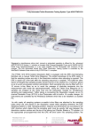
The Symmetric Research PARxCH family of 24 bit A/D data acquisition systems are
designed for acquiring high resolution data on the PC at sampling rates from DC to several
kHz. The x in the product name represents the number of analog channels and can be 1, 4, or
8. In addition to the analog channels, these A/D boards can also acquire one bit of
information from each of 4 digital channels.
Connecting to the PC parallel port, the PARxCH sits outside the PC in its own vinyl covered
steel enclosure for quiet noise free operation. Because it interfaces to the parallel port, the
system is easy to use with closed PCs such as laptops.
Based on the Burr Brown ADS1210 24 bit sigma delta A/D converter, the PARxCH has an
individual converter per channel architecture. This minimizes channel cross talk, skew, and
settling time. You get the full performance of a dedicated A/D converter on each channel.
The AS1210 converters are "instrument grade" meaning they maintain full accuracy right
down to DC. In addition, data from the A/D converters is buffered with a deep 2Mb memory
array on the PARxCH. This allows for continuous data acquisition even with long PC task
switching latencies.
Software that comes with the board has both high level finished applications ready for
immediate use and low level function libraries for those wishing to do custom programming.
Support is provided for DOS, Win9x, Win2000/XP, Linux, and LabView. The Win2000/XP
and Linux software features true kernel mode drivers for good performance and reliable
operation.
Other items included with the system are a 9vdc wall transformer, a cable for connecting to
the PC parallel port, an analog input terminal board, and circuit diagrams. Everything needed
to be up and running right away.
We hope you enjoy using the SR PARxCH
1
INSTALLATION
INSTALLATION
Installation of the PARxCH is straightforward. You'll need to plug in the wall transformer,
connect to the PC parallel port, install the software, and provide suitable analog inputs. The
individual steps in more detail are:
CONNECTING POWER
The PARxCH requires power independently of the PC. Included with the system is a 9vdc
wall transformer. This wall transformer should be plugged into a 110vac wall socket, and the
9vdc connector plugged into either of the two power jacks on the back of the PARxCH. The
second power jack is available for daisy-chaining power to optional equipment such as the
PARGPS time stamping unit. Many of our international customers will have been provided
with a 220vac wall transformer. Refer to the label on the wall transformer for compatibility
with your local wall power.
Once plugged in, you can verify the wall transformer is on by checking the right hand side
green LED near the power connector on the back of the PARxCH. If it is on, your wall
transformer is plugged in and powered on.
The left hand side green LED on the back of the PARxCH near the DB25 parallel port
connector indicates whether the PC has sent a "power up" or "power down" signal to the
PARxCH. In its power down mode, the PARxCH draws very little current. This can be
useful for applications requiring only occasional data acquisition, helping to preserve the
life of field batteries etc. Turning off your PC will also automatically power down the
PARxCH.
The PARxCH can be powered with a wide range of wall transformers. Any AC or DC wall
transformer with a voltage between 9 and 24 volts is acceptable as long as it has a 2.1mm,
center-plus plug. If you have a choice, chose a voltage nearer to 9 volts rather than 24.
Running at lower power supply voltages will reduce the heat dissipation of the internal
regulators. If you are running the PARxCH outside of its enclosure in a PC104 application,
you can also use the alternative power connector. The exact style and location of this
connector depends on which of the PARxCH boards you are using, so please consult the
circuit diagrams and board legend for proper connections.
The PARxCH is protected with diodes so that it is unlikely incorrectly connected power
supplies will damage it. However, the PARxCH is not protected from excessive
overvoltages. Connecting either AC or DC power that is badly out of range may damage the
board. Customers using their own power supplies should be aware that they are responsible
2
INSTALLATION
for providing the correct voltages. Please read the limited warranty at the beginning of this
manual.
CONNECTING TO THE PC PARALLEL PORT
Included with the PARxCH is a 6 ft molded 25 pin D-shell cable for connecting to the PC
parallel port. The female end of this cable should be connected to the D-shell connector on
the back of the PARxCH, while the other end should be connected to the parallel port
connector on your PC. Do NOT connect the cable to 25 pin RS232 interfaces or to the 25
pin analog inputs on the PAR8CH. Only connect to PC parallel ports.
The PARxCH has been designed to work with IEEE 1284 type EPP/BPP parallel ports. This
type of port has significantly improved performance over the standard Centronics/SPP
parallel port on the original PC. The PARxCH will also work with standard PS2 style
bi-directional BPP parallel ports found on many computers.
Most users with PCs manufactured after 1995 will have EPP compatible parallel ports even
though they may not realize it! To make sure you are running in EPP mode, check your
CMOS setup. Somewhere in the CMOS menus, you will find an option for selecting the
parallel port mode. Typical CMOS parallel port options are:
SPP
bi-directional
EPP
ECP
Standard Parallel Port mode
IBM PS2 style bi-directional parallel port mode
Enhanced Parallel Port mode
Enhanced Communications Port mode
Chose EPP mode for use with the PARxCH. EPP mode is backward compatible with SPP,
so you will be able to continue using other SPP peripherals you may have without
reconfiguring your CMOS again.
If your CMOS does not have EPP mode, then chose a bi-directional mode if possible.
Usually the word bi-directional will be included in the mode description, although there is
great variability from computer to computer. We have even found computers that support
bi-directional mode when the CMOS is set to SPP!
The EPP and bi-directional modes are also available indirectly as sub-modes of ECP. The
sub-modes for straight ECP and the common ECP/EPP variation are often implemented
differently from machine to machine. So you should run the diagnostic program in the diags
directory to verify which modes work on your machine for any given CMOS setting.
In addition, you will want to set the parallel port address. The SR software defaults to the IO
address 0x378. Most users will already find their CMOS assignment set to this address.
Although the SR software can be used with other addresses, we recommend using the 0x378
default.
3
INSTALLATION
Users with PC's manufactured before 1995, or lacking EPP/BPP compatible parallel ports
may wish to consider installing an Enhanced IO card in their ISA bus. These cards are
available at many computer stores. Check to make sure the card has IEEE 1284
compatibility. If it does, it will support EPP mode. These cards are inexpensive, usually
$40 or less. SR can also supply these cards if you need one.
If you use an Enhanced IO card in your PC you will probably have to configure it for EPP
mode by setting jumpers on the card rather than your CMOS. Refer to the documentation
that came with the card. Also configure the add-in card for base address 0x378 if possible.
So how do you verify if the PC's EPP port is communicating with the PARxCH board
correctly? After installing the software, run the diag program in the diags directory giving
std as the command line option. This will automatically check to see if a PARxCH board is
properly connected and let you twiddle the front panel yellow LED. If diag succeeds and the
yellow LED toggles, you are correctly connected to the PC.
SOFTWARE INSTALLATION
A CD-ROM is included with the PARxCH. Software for each supported operating system
can be found in the respective directory. Each OS subdirectory includes a readme.txt file, a
compressed PKZIP or Linux gzipped tar format file, and an installation batch or script file.
To install the PARxCH software, change to the OS subdirectory appropriate for your
computer and run the install batch script. This will automatically unzip and create the default
\sr\parxch or Linux /usr/local/sr/parxch directory structure on your hard disk.
We highly recommend you keep only one copy of the software on your hard disk and that
you use the default directory structure. This makes maintenance and installing upgrades
easier. See the readme.txt files on the CD for more information.
For Win2000/XP and Linux installations, besides copying the software to your hard disk,
you must also install a kernel mode device driver. Administrator or root permissions are
required for this step, but once the driver is installed, ordinary users can use it freely.
To install the kernel mode device driver, change to the PARxCH driver subdirectory on your
hard disk and run the indriver program with no arguments to see a list of valid driver names.
Then run indriver again with the name of driver associated with the parallel port you are
using.. You can remove the device driver using this name and the rmdriver program.
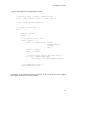
For example, to install the driver on LPT1 at address 0x378 and interrupt 7 with the
PAR8CH as the default model use:
> indriver PAR8CH 0x378 7
To remove it use:
> rmdriver SrParXch0
4
INSTALLATION
If you forget the exact assigned device driver name, you can find it using the showdriver
utility or on a list of installed drivers provided by the OS. For Win2000/XP use the Device
Manager and look under the SR Instrumentation group. For Linux, run /sbin/lsmod. For
additional information on installing the device driver, please refer to the readme.txt file in
the driver subdirectory.
If you have the PARxCH powered on and connected to your PC's parallel port, you can verify
correct operation by running the diag program located in the diags directory. This program
is designed to be run from a command prompt. Follow the on screen messages for more
information.
For programmers, the core part of the software supplied with the system is a collection of
low level functions that are required to communicate with the PARxCH. For the 32 bit
Windows systems, these functions can be linked in statically or used dynamically from the
Dynamic Link Library parxch.dll. Programs that use parxch.dll dynamically must be able to
find it at run time or Windows will give an error message. The best way to inform the
system of the location of parxch.dll is to add its location to your execution path. The
following command can either be executed from the command line or added to your
autoexec.bat file:
> set path=%path%;\sr\parxch\lib
For Linux systems, the core low level functions can also be linked in statically or used
dynamically from the shared library parxch.so. Programs using the shared library
dynamically should set the LD_LIBRARYPATH environment variable so the library can be
found at runtime. One way to do this is by executing the following command line or adding
it to your .profile file:
LD_LIBRARYPATH=$LD_LIBRARYPATH:/usr/local/sr/parxch/lib ; export \
$LD_LIBRARYPATH
Finally, note that the PARxCH requires exclusive access to the parallel port. Do not daisy
chain other physical devices or software drivers from the PARxCH port. Under multitasking
OS's, these drivers can contend for the parallel port while the PARxCH is executing. HP
printer drivers are known to cause trouble in this regard. Click on the HP printer driver
dialog Exit button to disable it at run time. Note: While daisy-chaining devices off the
parallel port will not work, it is perfectly fine to daisy-chain power to other devices like the
PARGPS as long as the total current draw does not exceed the wall transformer specs.
Included with the software are many readme.txt files and source code files with comments.
We encourage you to refer to these for more information about the software.
5
INSTALLATION
CONNECTING ANALOG INPUTS AND ANALOG GROUND
To complete installation you will want to connect analog inputs to the PARxCH board and
verify you are getting the correct values.
Inputs to the PARxCH are differential. Differential inputs provide significant noise
immunity over single ended inputs, but also require some care to use them correctly. The
basics are as follows:
Access the analog inputs by connecting to the 25 pin D-shell connector on the left hand side
of the front panel. The input pins are organized into pairs starting from the left of the
connector, where the (+,-) signal pairs are grouped on the connector. For the PAR1CH,
channel 0 is on pins (1,6). For the PAR4CH, channels 0 to 3 are on pins (1,9) (2,10) (3,11)
(4,12) respectively. For the PAR8CH, channels 0 to 7 are on pins (1,14) (2,15) (3,16)
(4,17) (5,18) (6,19) (7,20) (8,21) respectively. The remaining pins are analog ground.
Quick reference information is also printed on the label on the bottom of the PARxCH
enclosure.
To make simple wire connections to the analog inputs, you may wish to use the TRM15E or
TRMxxV terminal board included with the system. Note, that the numbers listed along the
screw edge of the terminal board are not the same as the D-shell pin numbers. The terminal
board is numbered so that screws (1,2) are channel 0 (+,-) etc. A number of other analog
input connector options such as solder-cup D-shells are also available from SR.
The A/D converters return a count which is proportional to the difference in voltage between
the + and - input pins. However, they can only do this within limits. If the absolute common
mode voltage is too high then the converters will be beyond their specifications. To
maintain a common analog ground, you must connect at least one of the analog
ground pins to your analog ground reference. The analog ground pins are 2-5 and 7-9
for the PAR1CH, 5-8 and 13-15 for the PAR4CH, and 9-13 and 22-25 for the PAR8CH.
If the analog ground of the PARxCH is floating with respect to the analog ground of your
input circuit, then it will likely drift with time and pin the A/D converters. A system that is
initially working may appear to start failing. This condition usually does not cause
permanent damage. Connecting the PARxCH analog ground pins to your input analog ground
reference will avoid this. Note that simply connecting the - input of a PARxCH channel to
your analog ground will work, but essentially turns the differential inputs into single ended.
The full scale analog input voltage range of the PARxCH is +/-10v. This means that if the +
pin is at +10v and the - pin is at -10 volts, for a total difference of +20v, you will record the
full positive counts. The full negative counts are recorded when the situation is reversed
with -10v on the + pin and +10v on the minus. This means the 2**24 possible digital counts
are spread over a range of 40 volts, which results in a scale factor of roughly 420,000 counts
per volt or about 2 microvolts per count.. The system will survive modest overvoltages
without any damage, but overvoltage conditions should be avoided. For example, do not
6
INSTALLATION
apply a static shock to the analog input pins. Symmetric Research reserves the right to
determine when systems have been damaged by excessive overvoltage. See the warranty
page at the beginning of this manual.
Finally, note that any analog inputs left floating tend to be susceptible to noise. When doing
tests for channel resolution, or simply to suppress noise, short unused inputs together.
To acquire some values and verify the results, use the simp or scope programs.
CONNECTING DIGITAL I/O
The 15 pin D-shell connector on the right hand side of the front of the PARxCH enclosure is
for digital input and output. Pins 1-4 are for input and pins 5-8 are for output. Pins 9-15 are
digital ground. As with the analog input D-shell connector, a TRM15E or TRM15V terminal
board can be attached to the digital I/O D-shell connector for simple wire connections.
Note, that the numbers listed along the screw edge of the terminal board are not the same as
the D-shell pin numbers. The terminal board is numbered so that screws (1,2) are pins 1 and
9, etc. The yellow LED provides an additional digital output bit that is under program
control.
7
INSTALLATION
INSTALLATION CHECKLIST:
*
Plug in the wall transformer and check the green LED on the right hand side of the
PARxCH back panel. If it is not on, the wall transformer is off or otherwise failed.
*
Connect the supplied 25 pin D-shell cable to your PC parallel port and run the
diagnostic program in the diags directory. This will show whether the PC's parallel
port is correctly connected or not. If diag reports an error, check your CMOS
settings for the correct parallel port mode. Also check to be sure the kernel mode
device driver is installed for Win2000/XP and Linux.
*
Connect analog signals from your source devices to the input pins on the analog
input D-shell connector on the left. Be careful to avoid static discharges when
touching the analog input pins.
*
Try out the simp and scope programs to acquire some data and see the system work.
If you are using dynamically linked libraries, make sure the \sr\parxch\lib directory
is on your execution path or Linux LD_LIBRARY path so parxch.dll or parxch.so
can be found at run time.
*
Connect an analog ground from your source devices to the analog ground pins on
the analog input D-shell connector. Even though the PARxCH inputs are
differential, they still require an analog ground reference to avoid clipping.
*
Do not touch the PARxCH analog input circuitry while in use. Your body has
voltages that will easily corrupt 24 bit accuracy. Short out any channels not in use.
Floating channels are susceptible to noise.
8
FINISHED APPLICATIONS
FINISHED APPLICATIONS
SIMP, SCOPE AND OTHER PROGRAMS
The SR PARxCH comes with finished application programs you can run immediately after
installing the system. These programs will help you become more familiar with the system
and may also fill your entire acquisition needs. The source code is included for those
wanting to modify these programs for custom applications.
The simp and scope programs have both been written in C. Simp is a simple text only
command line program, while scope has a full Windows GUI graphical interface and display.
Under Linux, only the simp program is available.
In addition to these basic data acquisition programs, the PARxCH software also includes
several other interesting programs. These are briefly described below.
For more details than covered here, refer to the readme.txt files in the corresponding
directories and comments in the source files.
simp
This program is a simple console program for text based data acquisition and is located in
the simple directory. It is designed to be run from a command prompt and save data to an
output file. Simp is appropriate for applications divided between many windows, where one
window acquires data while other windows perform downstream processing.
The initialization parameters for simp are specified in the file simp.ini. Refer to inisyntx.txt
for details about its syntax and parameters.
scope
This is a Windows GUI application and is located in the scope directory. It displays data as
horizontal traces on the screen in oscilloscope like fashion.
To start scope, execute it from the Windows command line or the Windows Start menu Run
command. When the program is running, you can select from menu commands to control
the program features such as sampling rate, output file names and display properties.
Besides using the scope menus, you can also control the program features from an
initialization file. This file can be given on the command line when starting scope or read in
from the Options menu after scope is running. A default initialization file scope.ini is
9
FINISHED APPLICATIONS
provided, but you can also generate one that reflects your current scope menu settings at any
time from the Options menu.
Refer to the online help and readme.txt file for more information about scope and refer to
the scope.ini initialization file and inisyntx.txt for details about its syntax and parameters.
There is no DOS or Linux version of the scope program since the graphical user interface
requires the Microsoft Foundation Class (MFC) library and must be able to find the MFC
DLL files at run time. It is assumed that users wanting graphical output will at least be
running Windows 95. However, for LabView users, there is a finished scope like application
program written in LabView. Refer to the following LabView chapter for more information.
view
This is a Windows GUI program located in the view directory for viewing previously
acquired .OUT or .DAT data files as horizontal traces on the screen. You can easily scroll
forwards and backwards through the data files. There is no DOS or Linux version of this
program.
diag
This is a simple diagnostic program that lets you verify your board is functioning correctly.
It is located in the diags directory and tries several parallel port address and mode
combinations to determine which is the best setting for your computer. It also allows you to
toggle the yellow LED on the PARxCH front panel.
sample
Located in the examples directory, sample is a very basic text only program to acquire and
display data. It shows the essential features of interacting with the PARxCH. For full
featured acquisition, see the simp program in the simple directory.
meter
This is a command line, text only data acquisition program that demonstrates one way to use
the PARxCH at slower sampling rates. It is located in the meter directory and includes
comments describing how to determine the channel offsets for use in a calibrated system.
For LabView users, there is a finished meter like program with a graphical interface. Refer
to the following LabView chapter for more information.
10
FINISHED APPLICATIONS
2task
Multitasking systems such as Windows and Linux allow several tasks or programs to run at
the same time. The 2task directory includes a demo batch or script file that shows how to
run the simp acquisition program while simultaneously running a "downstream" processing
program to perform some additional functions on the acquired data. Under Linux, the
acquisition task is run in the background and the processing task is run in the foreground.
While under Windows, both tasks are run in separate windows.
digio
This is a command line, text only program that lets you test the digital I/O. See the
comments at the top of the source file for information on how to set up a simple loopback
test jig using a terminal board and a few wires.
Conversion programs: out2asc, dat2asc, out2sud, dat2sud, etc
The convert directory has several subdirectories that contain programs for converting the
.out or .dat binary data files output by simp and scope into other formats. Currently,
converters are provided for ASCII text and IASPEI SUDS formats. Under Linux, converters
for the Seismic Unix (SU) format are also provided. Additional converters will be added in
the future. The existing conversion programs can also serve as an example for writing
customized converters to your preferred data format.
11
DLL LIBRARY SUPPORT
LIBRARY FUNCTIONS
The library functions are at the core of the software supplied with the SR PARxCH. They
allow users to control board operation from high level languages without having to know the
low level details of how the system operates. These functions can be statically linked to C
programs for any OS. In addition, they are available as a Dynamic Link Library (DLL) under
Windows and as a shared library (.so) under Linux. When used as a DLL, these functions can
be called from other high level programming languages such as Microsoft Visual Basic and
National Instruments LabView. This chapter covers usage from programming environments
like Visual C. For information about usage from LabView, see the LabView chapter. For
data acquisition applications that are ready to run with no programming required, see the
Finished Applications chapter.
The outline of how to use the PARxCH library functions is fairly simple. First call the Open
function to open the driver and initialize the sampling rate and other parameters. Once the
board has been initialized, call Start to begin acquisition. Then use ReadData to move the
data from the PARxCH FIFO into a PC memory array, after which it can be displayed or
saved to the hard disk. Also, the Ready function can be used to determine when the PARxCH
contains at least one point of acquired data. When you are done, call Stop and Close to stop
acquiring data and close the driver.
There are generally two schemes for determining when to call ReadData. The first is infinite
loop polling. While easy to program, this method wastes considerable PC horsepower. A
better way is to set up a PC timer tick that calls ReadData in about the time the PARxCH
takes to acquire the amount of data you want to read. This method greatly reduces the
number of PC cycles used in polling and fits in well with the multitasking capabilities of
Windows or Linux.
It is also possible to have the PARxCH interrupt the PC when the FIFO is ready with data.
Generally there is little improvement in performance using interrupts over a timer tick.
Interrupts are considerably more difficult to use with Windows than timer ticks, and we
generally recommend using a timer tick in most applications.
When using the parxch library functions, be sure to include the header file parxch.h in any C
source code. The prototypes in this file make sure the correct parameters are passed to the
functions. You will also find the defined constants in parxch.h useful for making your
programs more readable. When using dynamic linking, make sure the parxch.dll or parxch.so
library is on your Windows execution path or Linux LD_LIBRARY path so it can be found at
run time.
12
DLL LIBRARY SUPPORT
The following is a discussion of each PARxCH library function. Refer to the programs
simp.c and scope.cpp for examples of how to use the library functions. For a bare bones
program demonstrating how to use the library, refer to sample.c in the examples directory.
13
DLL LIBRARY SUPPORT
OPEN AND CLOSE DEVICE
C usage:
#include "parxch.h"
DEVHANDLE ParXchOpen(
char* DriverName,
int XchModel,
int PortMode,
double Sps,
double *ActualSps,
int *Error
);
int ParXchClose( DEVHANDLE handle );
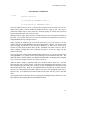
The Open function opens the PARxCH device driver and provides a device handle that is
passed to the remaining library functions. It also initializes the PARxCH board using default
values based on the requested sampling rate. Open should be the first library function called.
It returns a valid device handle on success and the value BAD_DEVHANDLE otherwise. If
the optional Error argument is provided, it is filled with an error code giving more detail
about why the open failed. See parxch.h for a list of the possible error codes. Pass NULL to
ignore this parameter.
Open takes a few parameter that identify the specific driver and model and control some
parallel port and ADS1210 A/D converter features and can be used as a presence test for the
PARxCH in addition to initializing it. Advanced users wanting more control over the
ADS1210 parameters can use the FullOpen function discussed later in the Advanced
Functions – FullOpen section.
The DriverName parameter identifies the device driver and therefore the parallel port base
I/O address. The XchModel parameter identifies which member of the PARxCH family is
being used: the PAR1CH, PAR4CH, or PAR8CH. The PortMode parameter controls the
parallel port mode that the parxch library will use in communicating with the board. Usually
DriverName is “SrParXch0” and PortMode is 0 to 3 indicating PS2 style bi-directional,
EPP, ECP/BPP, or ECP/EPP communications respectively. Use the defined constants in
parxch.h to specify these parameters and refer to the installation chapter of this manual for
more information about parallel port settings.
The Sps parameter is the desired number of samples per second. Because of how the A/D
converters work, not all sampling rates can be achieved. Open selects the closest achievable
rate and returns that value in the parameter ActualSps.
14
DLL LIBRARY SUPPORT
The Close function cleanly shutdowns the device driver. It should be the last library function
called. In some cases, it may be called implicitly at program termination. However, you
should not rely on this.
15
DLL LIBRARY SUPPORT
START AND STOP EXECUTION
C usage:
#include "parxch.h"
void ParXchStart( DEVHANDLE handle );
void ParXchStop( DEVHANDLE handle );
After successfully opening the device driver and initializing the PARxCH board, the next
step is to start acquisition by calling Start. Until Start is called, the ADS1210 A/D
converters are held in idle mode and do not sample their analog inputs. Calling Start signals
the converters to begin sampling their analog inputs and performing sigma-delta conversion.
Once acquisition is started you can use the Ready function to identify when the PARxCH
FIFO contains acquired data and the ReadData function to transfer that data over to the PC.
After you are done acquiring, call the Stop function to put the ADS1210 converters back into
idle mode and halt their execution. Calling Stop is optional, but if you do not, the converters
will continue executing until the Close function is called.
If you want to re-start acquisition once the A/D converters have been halted, you should reinitialize the PARxCH by first calling Close and Open before calling Start again. This
ensures that the A/D converters on the board are in a known state so they will begin
executing correctly.
16
DLL LIBRARY SUPPORT
READ DATA
C usage:
#include "parxch.h"
unsigned int ParXchReadData(
DEVHANDLE handle,
long *Values,
unsigned int Nvalues,
int *Error
);
ReadData copies data from the PARxCH FIFO to the PC where it is available for further
processing. It also implicitly checks whether data is ready before reading and whether
overflow or bad on board voltage has occurred. Because of these checks, ReadData may be
the only function you need besides Open/Close and Start/Stop.
To use ReadData, you need an array to hold the data values and the dimension of that array,
Nvalues. ReadData reads as many data points as possible into that array up to Nvalues. It
returns the number of points actually read. This will always be a multiple of the number of
analog channels (x), but may be zero if no complete data values are ready yet. To read a
single point for each channel, just pass 1, 4, or 8 for Nvalues as appropriate.
The optional Error parameter will be filled with 0 if all is well and with an error code if
something has gone wrong. See parxch.h for a list of the possible error codes. You can
ignore this parameter by passing NULL.
How is the data returned by ReadData organized? Values are returned in multiplexed fashion.
When using the PAR8CH, for example, the first value from channel 0 will be in Values[0],
the first value from channel 1 in Values[1], and so on. The second converted value from
channel 0 will be in Values[8], where in general the value from the nth conversion on channel
c will be given by:
Value at nth conversion from channel c = Values[n*8 + c]
Each 24 bit A/D value is stored as a long 32 bit integer. The format of this number is a
standard 32 bit two’s compliment signed value, unless you request an unsigned offset binary
value by setting the df parameter in the advanced FullOpen function. See the Advanced
Functions - FullOpen section for a discussion of the df parameter and Appendix B for more
details on the possible data formats.
17
DLL LIBRARY SUPPORT
A typical code fragment for using ReadData would be:
/* Declare an array to contain acquired values. */
Values = (long *)malloc( Nvalues * sizeof( long ) );
/* Open driver and start execution ... */
...
/* Acquire and process data. */
while ( 1 ) {
Nremain = Nvalues;
NextPt = 0;
/* Get Nvalues worth of data. */
while ( Nremain > 0 ) {
Newpts = ParXchReadData(
handle,
&Values[NextPt],
Nremain,
&Err );
Nremain -= Newpts;
NextPt += Newpts;
/* Check for FIFO overflow and other errors. */
if ( Err != PARXCH_ERROR_NONE )
Error("Error %s\n",PARXCH_ERROR_MSG[Err]);
}
/* Do something with data. */
SaveValuesToDisk( Values );
}
See sample.c in the examples directory and simp.c in the simple directory for complete
code listings showing how to use this function.
18
DLL LIBRARY SUPPORT
READ DATA WITH DIGITAL AND/OR GPS
C usage:
#include "parxch.h"
unsigned int ParXchReadDataWithDigital(
DEVHANDLE handle,
long *Values,
unsigned int Nvalues,
int *Error
);
unsigned int ParXchReadDataWithGpsMark(
DEVHANDLE handle,
long *Values,
unsigned int Nvalues,
int *Error
);
unsigned int ParXchReadDataAll(
DEVHANDLE handle,
long *Values,
unsigned int Nvalues,
int *Error
);
In addition to the standard ReadData function which copies the acquired analog data from the
PARxCH FIFO to the PC, there are three variants which provide additional data. While the
argument list is identical for all the read data functions, the size of the Values array will
differ and must be large enough to hold all the data being requested.
Because of additional firmware enhancements beyond those found in the 1 and 4 channel
units, the PAR8CH can record the values of the digital inputs when each analog sample is
ready. Requesting this digital data adds one additional channel beyond the 8 analog channels.
The low 4 bits of this additional 32-bit integer channel contain the values of the 4 digital
input lines sampled when the related analog data is ready.
Requesting GPS data adds one additional channel beyond the 1, 4, or 8 analog channels. This
additional channel contains the PPS event number, often referred to as the GPS mark, which
is used to correlate the PPS with its associated serial NMEA data. For the PAR8CH,
requesting GPS data also adds a second additional channel containing the results of an onboard counter. This on-board counter records the number of 800ns counts between the time
the PPS signal arrives and the time when the next analog data sample is ready. Because this
19
DLL LIBRARY SUPPORT
counter is unaffected by interrupt latencies in the OS, the PAR8CH provides a further
improvement to the already accurate GPS time-stamping available with the 1 and 4 channel
units.
If both digital and GPS data are requested for the PAR8CH, there will be 3 additional
channels as described above. However, because the PARGPS PPS signal will be coming in
on digital input 3, that line is no longer available for simple digital data. So the
corresponding bit is zeroed out in the returned digital channel.
As with the standard ReadData, the optional Error parameter for all the variants will be filled
with 0 if all is well and with an error code if something has gone wrong. See parxch.h for a
list of the possible error codes. You can ignore this parameter by passing NULL.
20
DLL LIBRARY SUPPORT
DATA READY / OVERFLOW
C usage:
#include "parxch.h"
int ParXchReady( DEVHANDLE handle );
int ParXchOverflow( DEVHANDLE handle );
Once the PARxCH device driver is opened and execution has been started, you can use
Ready and Overflow to check whether the PARxCH FIFO is empty or full. They can be
polled in an infinite loop or with a timer tick. Generally polling via a timer tick is preferred
because that makes better use of the PC's CPU.
When the FIFO is empty, Ready returns 0. Ready returns 1 as soon as any data is available in
the FIFO. Once all the data has been read out of the FIFO and transferred to the PC by
calling ReadData, Ready will again return 0.
When acquiring at sampling rates lower than about 40 Hz, it may be easiest to use the
implicit ready check inside ReadData rather than calling Ready explicitly. The reason is that
extra averaging, beyond that in the converters themselves, is done in the device driver
software to ensure high resolution below 40 Hz. ReadData will return 0 until it is able to
read a complete averaged data point, but Ready will return 1 as soon as a single raw data
point is in the FIFO.
You may also want to check for the PARxCH FIFO overflowing. If you wait too long before
calling ReadData, it is possible for the FIFO buffering to be exceeded and data lost. The
PARxCH buffer is actually 2Mb in size (4Mb for the PAR8CH)! Depending on the sampling
rate, you can wait a long time before an overflow will occur.
When the FIFO is empty or partially filled, all is ok and Overflow returns a 0. Once the
FIFO becomes full, Overflow returns 1 and latches this information until the FIFO is reset.
This means that once an overflow has occurred, you can call ReadData to download the valid
data currently in the FIFO. However, any additional data arriving after the overflow would be
corrupt, so it is discarded and Overflow continues to return 1 even though the FIFO may no
longer be full. To re-initialize the PARxCH and reset the FIFO, call Stop, Close, Open and
Start.
The programs meter in the meter directory and simp in the simple directory show how to use
these functions while getting data from the PARxCH board.
21
DLL LIBRARY SUPPORT
GPS
C usage:
#include "parxch.h"
void ParXchAttachGps( DEVHANDLE handle
DEVHANDLE GpsHandle,
int *Error );
void ParXchReleaseGps( DEVHANDLE handle );
The PARGPS board can be used to accurately time stamp data acquired by the PARxCH. For
the two boards to work together in this fashion, both the boards and their drivers must be
connected to one another. The physical link is made by connecting the PPS signal from the
PARGPS to digital input 3 on the PARxCH. The software link between the drivers is made
by calling the AttachGps function and passing in the handle to an opened PARGPS driver.
The ReleaseGps function should be called to clean up this software when it is no longer
needed.
22
DLL LIBRARY SUPPORT
USER DIGITAL I/O & USER LED
C usage:
#include "parxch.h"
void ParXchUserIoRd( DEVHANDLE handle, int *Value );
void ParXchUserIoWr( DEVHANDLE handle, int Value );
void ParXchUserLed( DEVHANDLE handle, int State );
The PARxCH board has user programmable digital I/O with 4 input bits and 4 output bits that
can be used to communicate signals to or from external equipment. The physical signals are
available on the 15 pin D-shell connector on the right front of the enclosure or on the upper
right edge of the PARxCH board. An additional output bit is connected to the yellow LED.
To read the input bits, call UserIoRd. To program the output bits, call UserIoWr with the
desired output value. Call UserLed with 1 to turn the yellow LED on and with 0 to turn it
off. Before these functions will work, Open must be called to open the PARxCH device
driver and initialize the parallel port.
In addition to digital input, the inverted value of bit 3 is mapped to the parallel port interrupt.
Enable or disable this function with the InterruptEnable and InterruptDisable functions
discussed below.
See diag.c in the diags directory for an example of how to use UserLed.
23
DLL LIBRARY SUPPORT
PC INTERRUPT
C usage:
#include "parxch.h"
void ParXchInterruptEnable( DEVHANDLE handle );
void ParXchInterruptDisable( DEVHANDLE handle );
The PC can be interrupted by sending a signal over the parallel port. These functions enable
and disable this capability. Before these functions will work, Open must be called to open
the PARxCH device driver and initialize the parallel port.
24
DLL LIBRARY SUPPORT
VOLTAGE GOOD
C usage:
#include "parxch.h"
int ParXchVoltageGood( DEVHANDLE handle );
VoltageGood returns 1 if the voltage on the PARxCH board is good (within 1% of 4.75
volts). It returns 0 otherwise. Open must be called to open the device driver and initialize
the parallel port before this function will work.
The VoltageGood function reports the state of the voltage good signal. This signal is sent
from the PARxCH board via the parallel port’s Parallel Error pin and is active low. When
the PARxCH is not properly receiving power from the wall transformer, it does not have any
power available to drive the voltage good signal high to indicate the bad voltage. In this
situation, it relies on the PC having a pull-up resistor for this pin so floating inputs are
brought high. Most PC’s include this pull-up, but some do not. You may wish to add a pullup to your computer if that is the case.
25
DLL LIBRARY SUPPORT
LIBRARY REV
C usage:
#include "parxch.h"
void ParXchGetRev( int *Rev );
GetRev fills the Rev argument with an integer representing the current revision number of
the parxch library. For example, a value of 201 indicates version 2.01.
26
DLL LIBRARY SUPPORT
ADVANCED FUNCTIONS - FULLOPEN
C usage:
#include "parxch.h"
DEVHANDLE ParXchFullOpen(
char* DriverName,
int XchModel,
int PortMode,
int
int
int
int
int
int
Df,
GainLog,
TurboLog,
Decimation,
ExtraDecimation,
Unused,
long *ADS1210_CrValue,
int *Error
);
FullOpen opens the PARxCH device driver and initializes the PARxCH board while allowing
advanced users more control over the initialization parameters than the simpler Open.
FullOpen returns a valid device handle on success and the value BAD_DEVHANDLE
otherwise. If the optional Error argument is provided, it is filled with an error code giving
more detail about why the open failed. FullOpen takes several parameters controlling
various parallel port and ADS1210 A/D converter features and can be used as a presence test
for the PARxCH in addition to initializing it.
The DriverName parameter identifies the device driver and therefore the parallel port base
I/O address. The XchModel parameter identifies which model or member of the PARxCH
family is being used: the PAR1CH, PAR4CH, or PAR8CH. The PortMode parameter
controls the parallel port mode that the parxch library will use in communicating with the
board. Usually PortName is “SrParXch0” and PortMode is 0 to 3 indicating PS2 style
bi-directional, EPP, ECP/BPP, or ECP/EPP communications respectively. Use the defined
constants in parxch.h to specify these parameters and refer to the installation chapter of this
manual for more information about parallel port settings.
The next five parameters control the ADS1210 A/D converter chips by specifying their
sampling rate and other basic features. Note that all four ADS1210 A/D converter chips are
initialized and programmed in parallel with the same parameters. It is not possible to
program an individual ADS1210 with parameters that are different than the others. The
27
DLL LIBRARY SUPPORT
defined constants in parxch.h provide an easily readable way to work with these parameters.
The parameters are as follows:
Df stands for data format. It maps into the df bit in the ADS1210 control register
and controls whether signed integer or unsigned offset data is returned by the A/Ds.
The value of this parameter should be 0 for signed integer or 1 for unsigned offset.
GainLog controls the internal ADS1210 programmable gain amplifiers and maps
into the gain bits in the ADS1210 control register. This is an encoded value and not
the gain setting itself. Use the defined constants in parxch.h to set this value.
While the ADS1210 does have programmable gain, it gives the best performance
with a gain of 1 (GainLog = 0). Most applications are best served by using a gain of
1 and then shifting the digital values left to provide a software gain.
TurboLog maps into the turbo bits in the ADS1210 command register, controls the
internal ADS1210 modulator and affects the resolution. Use the SpsGainToTde
helper function to compute the values of turbolog, decimation, and extradecimation
corresponding to a particular sampling rate. FullOpen will fail if you specify a
sampling rate that is unacceptable for the ADS1210. Also, increasing the gain
reduces the available turbo options since the product of gain and turbo is fixed. For
best performance, use the maximum turbo value (TurboLog=4).
Decimation maps into the decimation bits in the ADS1210 control register, sets the
decimation value for the A/D converters and affects the native sampling rate. Use
the SpsGainToTde helper function to compute the values of turbolog, decimation,
and extradecimation corresponding to a particular sampling rate. FullOpen will fail
if you specify an effective sampling rate that is unacceptable for the ADS1210.
ExtraDecimation sets the amount of decimation done by the device driver in
addition to the native decimation done in the A/D converters themselves and affects
the effective sampling rate. Use the SpsGainToTde helper function to compute the
values of turbolog, decimation, and extradecimation corresponding to a particular
sampling rate. FullOpen will fail if you specify an effective sampling rate that is
unacceptable for the ADS1210.
Unused is not used at this time, but is included to allow for future improvements
without causing a change in the function prototype.
If ADS1210 converters are successfully initialized, the ADS1210_CrValue parameter will
be filled with the readback value from the ADS1210 control register. Besides checking the
FullOpen return, you can also check the bits in this value to make sure all ADS1210 control
register values were written out and read back successfully. Pass NULL to ignore this
parameter.
28
DLL LIBRARY SUPPORT
Besides returning a device handle, FullOpen also fills the Error parameter with an error code
indicating success or why it failed. See parxch.h for a list of the possible error codes. Pass
NULL to ignore this parameter.
29
DLL LIBRARY SUPPORT
A typical calling sequence for FullOpen would be:
#include "parxch.h"
DriverName
XchModel
PortMode
Df
Sps
GainLog
=
=
=
=
=
=
PARXCH_0;
PARXCH_MODEL_PAR4CH;
PARXCH_PORT_MODE_EPP;
PARXCH_DF_SIGNED;
50.0;
PARXCH_GAIN_1;
ParXchSpsGainToTde(
Sps,
GainLog
&TurboLog,
&Decimation,
&ExtraDecimation
);
handle = ParXchFullOpen(
DriverName,
XchModel,
PortMode,
Df,
GainLog,
TurboLog,
Decimation,
ExtraDecimation,
NULL,
NULL
);
if ( handle == BAD_DEVHANDLE )
printf( "error, unable to initialize");
30
DLL LIBRARY SUPPORT
ADVANCED FUNCTIONS – SPS HELPERS
C usage:
#include "parxch.h"
void ParXchSpsGainToTde(
double Sps,
int GainLog,
int *TurboLog,
int *Decimation,
int *ExtraDecimation
);
void ParXchTdeToSpsGain(
int TurboLog,
int Decimation,
int ExtraDecimation,
double *Sps,
int *GainLog,
);
The SpsGainToTde and TdeToSpsGain functions convert between the related parameters of
sampling rate, gain, turbo rate, native decimation, and extra decimation. For a description of
the different parameters, please refer to the Advanced Functions – FullOpen section above.
A typical calling sequence for SpsGainToTde and TdeToSpsGain would be:
#include "parxch.h"
Sps = 200.0;
ParXchSpsGainToTde( Sps, PARXCH_GAIN_1, &tl, &dec, &exdec );
ParXchTdeToSpsGain( tl, dec, exdec, &ActualSps, &ActualGL );
printf( "Requested Sps = %f\n", Sps );
printf( "
Actual Sps = %f\n", ActualSps );
31
LABVIEW SUPPORT
LABVIEW SUPPORT
Support for National Instruments LabView is provided in the LabView LLB VI library
parxch.llb in the labview directory. This LLB contains 3 application and 20 utility VIs. The
application VIs include complete data acquisition programs that rely on the underlying utility
VIs which are wrappers around the corresponding core parxch.dll DLL functions supplying
the low level support for all SR PARxCH software.
To use the PARxCH LLB library, put \sr\parxch\lib on your path so Windows can find the
core DLL at run time. You can then access the VIs by using the File>Open menu option to
open \sr\parxch\labview\parxch.llb. If it is more convenient to have those VIs available from
the User Libraries button on the Function Palette, you can do this using the Edit>Edit
Control & Function Palettes... menu option or by copying parxch.llb into the user.lib
subdirectory of your LabView directory. For further details, please refer to file
\sr\parxch\labview\readme.txt.
The PARxCH application VIs are described below. For additional information, please refer
to the descriptions of the underlying DLL functions or use the Window>Show VI Info...
menu option to access the information stored within each VI itself. The VIs have been saved
unlocked with their block diagrams included so you can modify them as needed to fit your
application.
PARxCH LED Demo
This VI is so simple, it does not even start acquisition. It just initializes the PARxCH and
allows you to toggle the on board yellow LED to visually verify that initialization was
successful.
To run the demo, use the LabView Operating tool to set the Port Mode switch and the Port
Name value as appropriate for your computer. Then press the Run Arrow on the toolbar. If
PARxCH initialization is successful, you can press the Toggle LED button. With each press,
both the yellow LED indicator on the LabView front panel and the physical LED on the board
will change state. To end the demo, press the red STOP button.
PARxCH Meter Demo
This VI samples the PARxCH at a slow rate and displays the results as digital readouts. After
the front panel controls have been set, the PARxCH is initialized and acquisition is started.
Ready is called to determine when a new sample for each channel is available. Then Read
32
LABVIEW SUPPORT
Data is called to read them in. Since the desired sampling rates are slower than the minimum
native rate that can be assigned to the ADS1210 A/D converters, several adjacent samples
are acquired and averaged together before being displayed. This additional averaging has the
added benefit of improving the resolution of the results.
The results can be displayed as “counts” or volts. When counts is selected, the 24 bits
received from the A/D converters are displayed as six hex digits. When volts is selected, the
count values are converted to volts by multiplying by a scale factor and adding an offset. The
scaling factor and offset are computed in the calibration frame using approximate default
values, but you will require different calibration values appropriate for each A/D chip before
the volts display is accurate.
To run this demo, press the Run Arrow on the toolbar to enable the Driver Name control, the
Xch Model control, the Port Mode switch, the Units switch, and the Sample Period dial.
Once these controls are set to their desired values, press the green START button to begin
acquisition. Acquisition will continue until you press the red STOP button to end the demo.
PARxCH Scope Demo
The scope demo samples the PARxCH at a faster rate and displays the results as horizontal
waveforms like an oscilloscope. In addition, both a header file containing information like
the channels and sampling rate, and a binary data file containing the data points are written
out to the LabView default directory that is set from the Edit>Preferences menu option.
These files use the same format as those output by the C language programs simp.exe and
scope.exe.
After the front panel controls have been set, the PARxCH is initialized, the header file is
written, and acquisition is started. Because the sampling rate for this demo VI is much faster
than for PARxCH Demo Meter, a buffer worth of samples is allowed to accumulate before
they are read from the FIFO instead of reading them one set at a time. So, Ready is called to
determine when one sample is available and Read Data is called repeatedly to read in a buffer
worth of samples which are written out and displayed on the multi-plot graph. To reduce
flashing as the graph is updated, check the “Use smooth updates” box from the
Edit>Preferences>Front Panel dialog.
To run this demo, press the Run Arrow on the toolbar to enable the Driver Name control, the
Xch Model control, the Port Mode switch, and the Sample Rate dial. Once these controls
are set to their desired values, press the green START button to begin acquisition.
Acquisition will continue until you press the red STOP button to end the demo.
33
LABVIEW SUPPORT
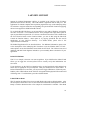
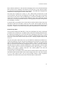
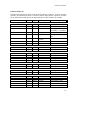
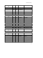
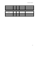
PARxCH Utility VIs
The following table lists the utility VIs in parxch.llb and their arguments. To allow complete
flexibility in controlling the flow of execution, dummy inputs and/or outputs are provided
for any function not having at least one input and output. PARxCH Start is an example.
Function
In/Out
Type
Description
Range
PARxCH Open
input
input
input
char
int32
int32
Driver name
Xch Model
Port mode
input
output
double
int32
Sampling rate
Device handle
output
int32
output
output
int32
double
ADS1210
CrValue
Error code
True sample rate
PARxCH Close
input
output
uint32
int32
Device handle
Close result
from Open
1 = ok, 0 = fail
PARxCH Start
input
output
uint32
Int32
Device handle
flow_out
from Open
Dummy
PARxCH Stop
input
output
uint32
int32
Device handle
flow_out
from Open
Dummy
PARxCH Ready
input
output
uint32
int32
Device handle
Ready result
from Open
1 = ready, 0 = not
PARxCH Overflow
input
output
uint32
int32
Device handle
Overflow result
from Open
1 = overflow, 0 = not
PARxCH Read Data
input
input
input
input
output
output
uint32
int32*
uint32
int32
int32
int32*
Device handle
Data values_in
Nvalues
Error in
Read Data result
Data values
from Open
SrParXch0, default
PAR1CH, PAR4CH,etc
0 = BPP, 1 = EPP, 2 =
ECP/BPP, 3 = ECP/EPP
2.44 to 15625, native
BAD_DEVHANDLE =
fail
see BB spec sheet
0 to 21, see parxch.h
max number to read
# values read
array of int32 values
34
LABVIEW SUPPORT
output
int32
Error
0 to 21, see parxch.h
PARxCH User Led
input
input
output
uint32
int32
int32
Device handle
User Led
flow_out
from Open
0 or 1
Dummy
PARxCH User IO Wr
input
input
output
uint32
int32
int32
Device handle
Value
flow_out
from Open
0x0 to 0xF
Dummy
PARxCH User IO Rd
input
input
output
uint32
int32
int32
Device handle
Value in
Value
from Open
input
uint32
Device handle
from Open
output
int32
flow_out
Dummy
input
uint32
Device handle
from Open
output
int32
flow_out
Dummy
input
input
input
char
int32
int32
Driver Name
Xch Model
Port mode
input
input
input
input
input
input
output
double
int32
int32
int32
int32
int32
uint32
Sampling rate
Data Format
Gain log
Turbo log
Decimation
ExtraDecimation
Device handle
output
int32
output
output
int32
double
ADS1210
CrValue
Error code
True sample rate
SrParXch0 default
PAR4CH, PAR8CH, etc
0 = BPP, 1 = EPP, 2 =
ECP/BPP, 3 = ECP/EPP
2.44 to 15625, native
0 = signed, 1 = offset
0 to 4 (for 1 to 16)
0 to 4 (for 1 to 16)
19 to 8000
1 default
BAD_DEVHANDLE =
fail
See BB spec sheet
PARxCH Interrupt
Enable
PARxCH Interrupt
Disable
PARxCH Full Open
0x0 to 0xF
0 to 21, see parxch.h
35
LABVIEW SUPPORT
PARxCH Sps Gain To
Tde
input
double
Samples / sec
2.44 to 15625, native
input
input
input
input
int32
int32
int32
int32
0 to 4
output
output
output
int32
int32
int32
Gain log
Turbo log in
Decimation in
ExtraDecimation
in
Turbo log
Decimation
ExtraDecimation
input
int32
Turbo log
0 to 4
input
input
input
input
output
output
int32
int32
double
int32
double
int32
Decimation
ExtraDecimation
Samples / sec in
Gain log in
Samples / sec
Gain log
19 to 8000
1 default
PARxCH Voltage Good
input
output
uint32
int32
Device handle
Voltage result
from Open
1 = good, 0 = bad
PARxCH Get Rev
input
output
int32
int32
Rev in
Rev result
201 means DLL rev 2.01
input
uint32
Nvalues in
output
uint32
Nvalues
Currently always 1 * 4
input
int32
Data format
0 = signed, 1 = offset
input
input
input
input
input
input
input
input
int32
int32
int32
path
string
error
int32*
string*
Word size
Record pts
Channels
File name
Id
Error in
Channel array
Channel title
4
Nvalues
1, 4, 8
Scope.hdr
SR PARxCH
PARxCH Tde To Sps
Gain
PARxCH Fifo Ready
Size
PARxCH Write Header
File
0 to 4
19 to 8000
1 default
2.44 to 15625, native
0 to 4
0,1,2,3,4,5,6,7 default
[1,4,8], 12 char
36
LABVIEW SUPPORT
PARxCH Write Data
File
input
input
input
input
output
float
float
float
float
error
Sample rate
Gain
Filter coeff
Filter scale
Error out
2.44 to 15625, native
0 => 2**0 to 4 => 2**4
0
1
input
path
File name
Scope.out
input
input
output
int32*
error
error
Wave array
Error in
Error out
Acquired data values
37
ELECTRICAL SPECS
APPENDIX A: ELECTRICAL SPECS
POWER SUPPLY REQUIREMENTS:
The PARxCH uses +5vdc to power the analog and digital circuitry. The on board voltages
are generated by linear regulators from the off board power supply, usually a wall
transformer, to provide quiet operation. The off board power supply must allow enough
voltage headroom for the on board regulators to operate. Off board power of at least 10
volts is recommended for reliable operation.
The system requires approximately 120ma of current. This figure is approximate because
the actual current draw depends on the sampling rate. Higher sampling rates result in more
current draw. We have found 120ma to be a typical maximum figure.
A 9vdc 500ma wall transformer is supplied with the system. When loaded at 120ma, it will
provide approximately 12vdc of output power, more than enough to adequately power the
PARxCH.
Other off board power supplies are acceptable. AC power will be rectified by the on board
circuitry and 9vac wall or chassis mount transformers are perfectly fine with no degradation
in system noise or resolution.
MAXIMUM ANALOG INPUT VOLTAGE RANGE:
The absolute maximum analog input voltage range of the PARxCH is +/-10v. This is mapped
by the on board circuitry to a 0 to 5v range that is compatible with the ADS1210 A/D
converters. Although the PARxCH analog inputs are protected by resistive current limiting,
do not exceed the recommended +/-10v input range, or you may damage the system. Static
discharges near the analog input pins should also be avoided.
All of the PARxCH analog inputs are differential. This means that the absolute difference
between the + and - inputs on any given channel must be less than 20 volts. In addition, for
the system to work correctly, you must establish a common analog ground that is connected
to one of the ground pins on the analog input D-shell connector. The inputs are differential
only up to the point where the A/D converters are pinned. When analog ground floats, it can
easily drift to absolute voltages that exceed the A/Ds common mode range even though the
absolute difference is still within range. Connecting an analog ground reference avoids this.
38
DATA CODING FORMATS
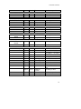
APPENDIX B: DATA FORMATS
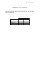
When programming the PARxCH, you can use the Data Format parameter, df, to choose the
format of the acquired data. The two choices are signed and offset. The Open function
defaults to the signed format.
When signed format is selected, the 24 bit data is sign extended and treated as signed 32 bit
values. When offset format is selected, the data is treated as unsigned two’s complement.
Selected values for both formats are shown in the following table:
Offset
Signed
Lowest value
0x00000000
0xFF800000
Mid-level, minus one
0x007FFFFF
0xFFFFFFFF
Mid-level, zero
0x00800000
0x00000000
Highest value
0x00FFFFFF
0x007FFFFF
39
DATA CODING FORMATS
APPENDIX C: OUTPUT FILE FORMATS
The acquisition programs simp and scope can output the acquired data to files in one of two
formats, .out files and .dat files. Additional utility programs, located in the convert
directory, are available for converting the binary .out and .dat data files into other formats
such as ASCII text or IASPEI SUDS.
The .out file format is very simple and contains only the multiplexed data values stored as
32-bit integers. The data is organized exactly as described for the ReadData function. The
first integer contains the data for point 0 of channel 0. The second has the data for point 0 of
channel 1. The Nth integer has the data for point 0 of channel N, while integer N+1 has the
data for point 1 of channel 0. And so on. All data is written out in the standard little-endian
PC byte order, where the low byte is written first.
When .out files are requested, the simp and scope acquisition programs also write a single,
separate header file with the .hdr extension. This file contains information such as sampling
rate and number of channels that apply to all the .out data files. The format of this header
file can be seen by looking at the HDR_data structure in the simp.h file in the simple
directory.
The .dat file format is more complicated as each file contains a 4096 byte header followed
by data records, possibly of many different types. The header begins with SrDatHdrLayout
structure defined and described in the srdat.h file in the include directory. The remaining
bytes of the header are padded with zero. Each data record is composed of a short 128 byte
record tag structure identifying the format and size of the following data and then the data
itself. The record tag structure and the currently defined data formats are described in the
srdat.h file. The .dat file header and data records are written out in standard little-endian PC
byte order.
Which data format is best? That depends on what you need. Most users will be happiest with
the .dat format since that keeps all the header information tightly associated with the data and
allows saving GPS PPS and serial data in addition to the analog and digital data. But, these
extra features do have a cost in terms of speed and complexity. So, users with high sampling
rates that only need analog and digital data may prefer using the simpler .out file format.
40
INDEX
INDEX
G
2
GainLog...................................................28
GPS..........................................................22
2task.........................................................11
H
A
Hardware installation................................ 2
Analog Ground, connecting........... 6, 8, 38
Analog Inputs
Connecting ............................................6
Full scale ...............................................6
Maximum voltage ...............................38
Application programs ...............................9
I
C
CMOS Setup..............................................3
Convert.....................................................11
D
Dat file format.........................................40
Dat2asc ....................................................11
Dat2sud ....................................................11
Data Format ...................................... 28, 39
Decimation..............................................28
Device driver
Installation.............................................4
Name.........................................5, 14, 27
Removal.................................................4
Df......................................See Data Format
Diag ...................................... 4, 5, 8, 10, 23
Diagnostic program .....................See Diag
Digio ........................................................11
Digital I/O
Connecting ............................................7
Functions .............................................23
DriverName .........See Device driver name
E
ECP/EPP/BPP................ See Parallel Port
Electrical specs.......................................38
ExtraDecimation.....................................28
IEEE 1284 ...................... See Parallel Port
Installation................................................. 2
Analog Connections ............................. 6
Checklist ............................................... 8
Device Driver........................................ 4
Digital I/O Connections ....................... 7
Hardware ............................................... 2
Software ................................................ 4
Interrupts ........................ See Parallel Port
Introduction............................................... 1
K
Kernel mode driver....... See Device driver
L
LabView Support.....................................32
LED
Green.................................................2, 8
Yellow........................... 4, 7, 10, 23, 32
Library functions ....................................12
ParXchAttachGps ...............................22
ParXchClose.......................................14
ParXchFullOpen.................................27
ParXchGetRev....................................26
ParXchInterruptDisable .....................24
ParXchInterruptEnable.......................24
ParXchOpen........................................14
ParXchOverflow.................................21
ParXchReadData.................................17
ParXchReadDataAll ...........................19
ParXchReadDataWithDigital ............19
ParXchReadDataWithGpsMark ........19
ParXchReady ......................................21
41
INDEX
ParXchReleaseGps .............................22
ParXchSpsGainToTde ........................31
ParXchStart .........................................16
ParXchStop .........................................16
ParXchTdeToSpsGain ........................31
ParXchUserIoRd.................................23
ParXchUserIoWr................................23
ParXchUserLed ..................................23
ParXchVoltageGood ..........................25
Library path, setting ..................................5
Software installation................................. 4
Sps..................................See Sampling rate
M
View.........................................................10
Meter........................................................10
Model.................................See Xch Model
T
TRM15E................................................6, 7
TRM15V.................................................... 7
TRMxxV.................................................... 6
TurboLog.................................................28
V
X
Xch Model........................................ 14, 27
O
Offset data format ...................................39
Out file format ........................................40
Out2asc ....................................................11
Out2sud....................................................11
P
Parallel Port
Connecting ............................................3
Daisy-Chaining......................................5
Interrupts .............................................24
Mode .........................................3, 14, 27
PARGPS ..................................................22
PortMode........................ See Parallel Port
Power supply
Connecting ............................................2
Requirements ......................................38
S
Sample......................................................10
Sampling rate....................... 14, 21, 28, 31
Scale factor
Counts per volt......................................6
Scope..........................................................9
Signed data format ..................................39
Simp ...........................................................9
42