1
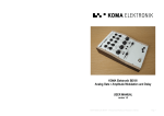
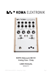
KOMA Elektronik BD101
Analog Gate / Amplitude Modulation and Delay
USER MANUAL
version 1.0
KOMA Elektronik BD101 – Analog Gate/Amplitude Modulation & Delay
Page 1
TABLE OF CONTENTS:
3. Introduction
4. Getting Started
5. Features
7. Control Voltage Theory
9. Patchbay
11. Basic Settings and Examples
13. Technical Specifications
15. Warranty
WARNING:
Ony use the KOMA Elektronik power supply shipped with the BD101. Power sources
rated with voltages greater than 9V DC and/or wrong polarity may cause damage or
malfunction to the BD101’s circuitry and will void the warranty!
KOMA Elektronik BD101 – Analog Gate/Amplitude Modulation & Delay
Page 2
INTRODUCTION
Analog delays have been a specialty in musicians effect artillery ever since. Being loved for their
organic, physical sounds, these circuits deserve special attention.... The way analog delays work is
very similar to the old fashioned way of extinguishing a fire by means of a bucket bridge
transferring water from the water source to the fire, therefor called bucket bridge delays (BBD). In
these BBD effects the sound is literally 'poured' from one transistor into the next one. This process
is clocked by a special bi-phase clock causing the first transistor to pass the signal to the second
one exactly at the moment the second transistor just finished doing that to the third transistor and
so on. Now imagine this procedure 2048 times in a row and you have successfully delayed your
signal by simple analog means!
Gating and especially amplitude modulation on the other hand are maybe one of the oldest tools in
the musicians repertoire to express dynamics and tension in music with the tremolo of a violin
possibly being the most classic example.
Now the KOMA Elektronik BD101 brings these great tools together and takes it one step further.
The bi-phase clock of the BBD circuit on the BD101 can go into ranges never intended by the
inventors of these chips allowing you to go from super short delay pulses to enormously cut-up
soundscapes. If you clock the BBD transistors in such a slow speed that the first transistor actually
misses a part of the incoming sound you are able to rip the incoming signal completely apart. At
times it might even sound like digital bit crushing. Because the gating/amplitude modulation circuit is
placed before the analog delay, it allows you to cut away portions of your sound before the signal
reaches the delay. That gives you the possibility to put focus on certain parts of your sound, e.g. a
certain snaredrum sound in your drumloop.
OK, these were the basics, now get your pedal, go to the next page and make some noise!
KOMA Elektronik BD101 – Analog Gate/Amplitude Modulation & Delay
Page 3
GETTING STARTED
1) Unpack your machine: The package comes with the BD101 pedal, a +9VDC, 500mA, tipnegative power supply, a small bag with 5 knobs and this manual. Save the box and packing
material in case you ever need to ship your pedal! Make sure that the power supply is rated
for the line voltage of your country: 120 VAC for the USA, 220 VAC for Europe or most other
countries.
Take the small knobs from the bag and gently push them in the holes of the backpanel of
the BD101. Please do this carefully! You can always take them out again when you transport
the pedal, this to make sure the attenuators on the back don't break down. When the pedal
is shipped, all the attenuators are turned fully counter clockwise and the trimmer for the
SENSOR is set fully clockwise.
2) Connect it: Be sure your amp is turned off, then connect your instrument to the BD101 by
using the AUDIO INPUT on the upper right of the patchbay. Connect the AUDIO OUT on the
upper left of the patchbay to your amp. To connect the Motion Controller (the built-in
expression function) plug in a ¼ inch jack cable from SENSOR to DLY TIME CV on the patch
bay.
3) Set up the BD101 / Amp: Set all the controls of the BD101 as in Fig. 1, see next page.
4) Power up / Bypass: Connect the BD101 power supply to the BD101 DC input on the backside
of the pedal. The GATE SPEED indicator will light up periodically. When you press the bypass
switch, the EFFECT ON/OFF led will light up, this means the effect is turned ON. Please wait
with playing for 5 seconds, so the unit can warm itself up. Turn your amp on now as well.
5) Set levels: Turn on your amplifier. Make sure the EFFECT ON/OFF indicator is OFF. Play your
instrument and adjust the volume of the amplifier so it is at a comfortable level. Press the
Bypass switch and the EFFECT ON/OFF indicator will turn on green which means the effect
is now active.
6) Play: Now go nuts. If necessary, adjust the INPUT GAIN slider control to match the levels of
the processed signal and the bypassed signal. The most predictable results will come from
playing single note riffs or melodies. This is especially true when the DELAY BLEND slider
control is set to WET. You can use the Motion Controller to adjust the DELAY TIME, GATE
SPEED, GATE AMOUNT and CYCLE. Be sure to read through the Control Voltage Theory
section to understand all CV features and their usage.
KOMA Elektronik BD101 – Analog Gate/Amplitude Modulation & Delay
Page 4
FEATURES
Fig.1 Frontpanel Features
Input Gain
The INPUT GAIN slider of the BD101 provides you with and adjustable gain for boosting low level
input signals. By sliding from left to right you can boost your signal from zero gain to 100 gain (0 to
+20dB).
Analog Gate / Amplitude Modulation
When the audio signal plugged into the AUDIO INPUT jack goes to into the BD101 it firstly arrives at
the analog gate / amplitude modulation section where you can choose in which way you want to
prepare your signal.
The SPEED knob sets the speed of the LFO (low frequency oscillator) that controls the amplitude
modulation. If turned fully counter clockwise, the speed is slowest, if turned fully clockwise you
select the highest speed. Together with the RANGE switch you can choose between three different
speed ranges.
With the gate SHAPE switch you can set the shape of the amplitude modulation / gate, selecting
either ramp, square or sawtooth shape. The amplitude modulation/gate will follow the selected
envelope.
After having selected a speed range with a respective clock speed and a gate shape you can
choose the impact of the gate / amplitude modulation section on your sound by turning the
AMOUNT knob. When turned fully counter clockwise your input signal isn't affected at all by the
LFO. The more you turn the knob in clockwise direction the more the LFO affects your signal, going
from a slight tremolo to severe amplitude modulation to completely gating your signal.
Analog Delay Section
After passing through the amplitude modulation / gate section your signal flows into the analog
delay (BBD) section of the pedal. You have two main controls to influence the processing of your
sound here.
KOMA Elektronik BD101 – Analog Gate/Amplitude Modulation & Delay
Page 5
First you can select the delay time with the TIME knob. Turning it fully counter clockwise will give
you a super short delay of 1ms. Turning it more clockwise will give you longer delay times. At
around 100ms you will notice slight degradation of the overall sound comparable to digital
bitcrushing effects. The further you turn the knob clockwise the harsher, noisier and more hearable
this effect will become.
This pseudo-bitcrushing effect is a side effect of clocking the BBD chips slower than it is actually
intended to be (see introductory notes about analog delay chips on page 3). Also be aware of the
fact that the clock of the BBD chip used in the BD101 will appear as a function of your input signal,
sitting on top of your waves. We don't consider this as a bug or malfunction but think that whoever
is brave enough to turn the TIME knob further than 100ms will either not care about this side effect
or love its sound the way we do at KOMA Elektronik.
The second control in the delay section is the knob labeled CYCLE which controls the amount of
delayed and amplitude modulated signal flowing back into the delay circuit, therefor representing
the amount of feedback in the delay circuit.
Delay Blend
The last feature influencing your sound in the signal processing chain is the DELAY BLEND slider.
You can choose how much of the delay signal is applied to your (amplitude modulated) input signal.
The slider is an equal-power panning slider which means that you go from completely dry – no
delay signal at all – to completely wet – only delayed signal – with no gain loss over the whole
range of the slider.
Sensor
One of the features on your BD101 you won't find in any other pedal is the possibility to control the
features of the pedals with the on board motion controller. Since its working with infra red LEDs we
call it the SENSOR. The motion controller can be used in many different ways. Technically speaking,
it emits a CV signal (control voltage) which can be patched up with any CV receptive socket on the
KOMA pedals and f.i. on your modular system. By moving your hand over the sensor you can
control the parameters of the CV input you patched it up to. With the trimmer on the back of the
pedal (it says SENSOR) you can change the sensitivity of the motion controller. For more
information about Control Voltage, check out the section Control Voltage Theory of this manual.
KOMA Elektronik BD101 – Analog Gate/Amplitude Modulation & Delay
Page 6
CONTROL VOLTAGE THEORY
The concept of control voltage (CV) is not hard to understand: Instead of turning a knob on your
pedal you simply connect a voltage – the control voltage – to the corresponding CV input that does
the job for you. So for example if you want to have quickly varying GATE AMOUNT you don't have
to turn that knob all the time back and forth fast until your fingers fall off but simply connect an
alternating CV to the AMOUNT CV input.
You can take control signals from any source for controlling the inputs of the BD101. All of the CV
inputs theoretically accept control voltages from -100V to +100V though a range from -5V/-12V/15V to +5V/+12V/+15V is more common and usable.
Since the BD101 is running on a +9V power supply you might wonder how you can use a signal as
large as -15V to +15V. The answer is simple: We provide you with a trimmer for each CV input on
the backside of the panel.
So whenever you notice a significant distortion or clipping in your control signal waveform or
strange CV behavior simply turn the trimpot clockwise (away from the word 'CV') until you hear your
desired result. By turning it clockwise you attenuate the incoming CV signal. Fully clockwise means
that the incoming CV signal is completely gone, whereas fully counter-clockwise means that the
incoming CV signal is arriving to the circuit unattenuated.
In addition to that you can set an offset voltage to your control voltage to adjust the CV signal to
your needs. The offset voltage is set by the corresponding knob on the front panel. There's also a
distinction between bipolar and unipolar signal. This is best explained with a few pictures.
KOMA Elektronik BD101 – Analog Gate/Amplitude Modulation & Delay
Page 7
So, what happens? The incoming CV signal is shifted around the voltage that you select with the
corresponding knob. Example: if you insert a -5V to +5V sine wave into the CYCLE CV jack you will
get the following results while turning the CYCLE knob:
Low Bias Voltage
High Bias Voltage
A similar thing happens to unipolar CV signals: Their point of origin (0V) is shifted by the amount set
with the corresponding knob. In other words: You add the voltage of your knob to the voltage of
you incoming unipolar CV signal.
Now that you understood the idea of control voltage, let's go on and see what the patchbay of the
BD101 can offer.
KOMA Elektronik BD101 – Analog Gate/Amplitude Modulation & Delay
Page 8
PATCHBAY
The patchbay consists of ten 1/4” jack sockets which you can use for receiving and sending
various audio or control voltage signals. Blank arrows mark CV inputs/outputs, black arrows mark
audio inputs/outputs. If the arrow is pointing towards the jack socket it shows you that this is an
output, if the arrow is pointing away from the jack socket it is an input.
All the CV inputs in the KOMA Elektronik pedals accept bi-polar control voltages. Since the pedal
runs on +9V every time you plug in a control voltage to one of the CV accepting inputs, the
respective knob (e.g. SPEED knob or SPEED IN (CV input) determines the offset voltage of your CV
input signal.
Let's start from right to left in the upper row.
AUDIO IN (audio input)
This is the main audio input of the BD101. The sound source plugged in here will go
trough the whole effect section.
CYCLE IN (audio input)
The sound source plugged in here will arrive at the feedback insert point of the BD101
delay section. You will mostly use this insert point together with the CYCLE OUT to
change the behavior/sound of your feedback cycle. This is a switching jack which
means that you break up the internal feedback circuit by plugging a sound source into
this jack.
CYCLE IN (CV input)
This CV input accepts control voltages from 0 – 9V, affecting the amount of feedback
in the delay section. When you insert a control voltage into this input the CYCLE knob
determines the offset voltage (see Control Voltage Theory section)
KOMA Elektronik BD101 – Analog Gate/Amplitude Modulation & Delay
Page 9
CYCLE OUT (audio output)
This output provides you with the audio signal after the delay section, before the
DELAY BLEND slider. If you send this output to an external effect like an EQ, Filter,
another delay unit etc. and plug the processed signal back into the CYCLE IN (audio
input), you can control the sound of the feedback. The volume of this signal is
determined by the setting of the CYCLE knob.
AUDIO OUT (audio output)
The main audio output of the BD101, plug your amplifier here, enjoy.
Left to right, lower patchbay row:
SPEED (CV input)
The SPEED CV input controls the speed of the amplitude modulation /gate LFO therefor
plugging a CV signal into this jack will change the speed of the LFO. When you insert a
control voltage into this input the SPEED knob determines the offset voltage (see
Control Voltage Theory section, pp xxx).
AMOUNT (CV input)
The AMOUNT CV input controls the amount of amplitude modulation /gate applied to
your incoming audio signal. When you insert a control voltage into this input the
AMOUNT knob determines the offset voltage (see Control Voltage Theory section).
EXT. GATE (CV input)
The EXT. GATE CV input goes directly to the VCA controlling the amount of the
amplitude modulation/gate, bypassing the SPEED and AMOUNT knobs and CVs which
means that any appropriate signal applied to this input will result in an according
amplitude modulation of your incoming signal.
DLY TIME (CV input)
The DLY TIME CV input controls the delay time of the delay circuit in the BD101. When
you insert a control voltage into this input the TIME knob determines the offset
voltage (see Control Voltage Theory section).
SENSOR (CV output)
This is the CV output of the infrared motion sensor. The closer you move something
towards the sensor, the higher the CV raises. You can set the sensitivity of the sensor
with a small trimmer on the background called 'Sensor'. The sensor output is 0 – 9V.
KOMA Elektronik BD101 – Analog Gate/Amplitude Modulation & Delay
Page 10
BASIC SETTINGS AND EXAMPLES
Chop your sound apart:
Classic analog delay:
KOMA Elektronik BD101 – Analog Gate/Amplitude Modulation & Delay
Page 11
Completely ripped apart:
Fast gate, short delay:
Karplus:
KOMA Elektronik BD101 – Analog Gate/Amplitude Modulation & Delay
Page 12
TECHNICAL SPECIFICATIONS
General
Case: Powder coated aluminium casing, silkscreened text and wooden sidepanels.
Dimensions: 23 cm x 15 cm x 5 cm (L x W x H) / 9″ x 6″ x 2″ (L x W x H).
Net. Weight: 800 gr / 1.7 lb.
Shipping Weight: 1 kg. / 3.0 lb including power adapter and instruction manual.
Power requirements: 9V DC power adapter, 500mA min, center polarity negative (only use the
KOMA adapter shipped with the pedal)
Features
INPUT GAIN - slide control which allows the user to set the input gain of the plugged in instrument
or line audio signal, 0 to +20dB variable gain.
DELAY BLEND - slide control to set the amount of processed delay signal within your overall sound
from completely dry to completely wet.
GATE SPEED - rotary control to adjust the speed of the gate.
GATE AMOUNT - rotary control which adjusts the amount of the gate signal applied to the audio
input signal, going from not influenced at all to amplitude modulated to completely gated.
CYCLE - rotary control to adjust the amount of processed signal fed back into the signal chain.
Going from no signal being fed back to 'usual' feedback sounds creating overtones and/or karplus
effects to going completely nuts with feedback.
DELAY TIME - rotary control to set the delay time. Please note that the delay chip used in this
circuit was never meant to go anywhere near the settings between 6 - 10 where serious bitcrushing like effects and other odd sounds start to appear.
GATE SHAPE - 3 pole toggle switch to switch between the 3 different shapes of the gate: ramp,
pulse and sawtooth.
GATE RANGE - 3 pole toggle switch to switch between high, mid or low speed range for the gate.
GATE SPEED LED - indicates the speed and shape of the gate clock.
EFFECT ON LED - indicates if the effect is switched on or bypass.
FOOTSWITCH - Heavy duty Alpha footswitch.Turning the effect on or off.
2 IR EMITTERS, 1 IR RECEIVER - calculates the distance between an object and the pedal and
generates a CV signal according to the measured distance. The CV output of this sensor appears as
a CV output on the patchbay from where you can route it to the CV input of your desired, to-bemodulated feature.
Patchbay
AUDIO IN - plug your sound source here.
AUDIO OUT - listen to what you created here.
CYCLE OUT - you can grab your processed signal here before it is being fed back into the circuit
here. By sending this signal into external effect units (e.g. filters or EQs) you can change the sound
being fed back into the pedal through plugging your externally processed sound into CYCLE IN.
CYCLE IN - by plugging an externally processed sound into this jack you break the internal CYCLE
circuit, thus being able to change the feedback sound in any way you desire.
CYCLE IN - CV input to control the amount of (internally or externally) processed signal being fed
back into the circuit.
SPEED - CV input to control the speed of the gate.
AMOUNT - CV input to control the amount of gate being applied to the plugged in signal.
EXT. GATE - CV input that allows you to control the gate by external gate and/or CV signals.
DLY TIME - CV input to set the delay time.
SENSOR - CV output of the onboard motion sensor for usage with CV inputs on the pedal, other
KOMA Elektronik pedals or other voltage-controlled devices.
KOMA Elektronik BD101 – Analog Gate/Amplitude Modulation & Delay
Page 13
Backpanel
DC POWER INPUT jack – accepts standard 9 volt power adaptors, center pin negative, 500mA min.
(KOMA Elektronik power adaptor included).
CV TRIMMERS - The sensitivity of the CV inputs and outputs as well as the sensitivity of the motion
sensor can be adjusted with attenuators which are mounted on the back of the pedal.
All patchbay inputs and outputs are mono 1/4″ phone jacks.
KOMA Elektronik BD101 – Analog Gate/Amplitude Modulation & Delay
Page 14
WARRANTY
KOMA Elektronik warrants its products to be free of defects in materials / workmanship and
conforming to specifications at the time of shipment for a period of two years from the date of
purchase. During the warranty period, any defective products will be repaired or replaced, at KOMA
Elektronik's option, on a return-to-factory basis. This warranty covers defects that KOMA Elektronik
determines are no fault of the user.
Returning Your Product?
You must obtain prior approval in the form of an RMA (Return Material Authorization) number from
KOMA Elektronik before returning any product. Click “Service” in the Support menu on the KOMA
Elektronik website (www.koma-elektronik.com) to request the RMA number . All products must be
packed carefully and shipped with the KOMA Elektronik supplied power adapter. Sorry, the
warranty will not be honored if the product is not properly packed. Once you have received the
RMA# and carefully packed your product, ship the product to KOMA Elektronik with transportation
and insurance charges paid, and include your return shipping address.
What will we do?
Once received, we will examine the product for any obvious signs of user abuse or damage as a
result of transport. If the product has been abused, damaged in transit, or is out of warranty, we will
contact you with an estimate of the repair cost. Warranty work will be performed and KOMA
Elektronik will ship and insure your product to your European / USA address free of charge.
How to initiate your warranty?
Please initiate your warranty online at www.koma-elektronik.com. Click “Product Registration” in
the Support menu to register your product. If you do not have web access, fill out all the
information on a letter and mail to:
KOMA Elektronik VOF
Postfach 610383,
10926 Berlin
Germany
KOMA Elektronik BD101 – Analog Gate/Amplitude Modulation & Delay
Page 15