1
N
L3
L2
Y / GN
BK
BL
RD
52C
NR
T2
T1 CM T3
(49C)
6
5
4
3
2
1
BL
RD
WH
OR
OR
CnM1
OR OR
CnM1
(49FO1)
FMO1
CnM1
BK
BK
BK
CFOI
Mark
CFI
CFO1,2
CH
CM
CnA ~ W
DM
F
FMI
FMO1,2
FS
LED1
LED2
LM
LS
NR
PC
SW
SW2, 3
TB
BK
CnP
OR
OR
CnM2
OR OR
CnM2
(49FO2)
FMO2
CnM2
CH
CnP
52C
BK
CFO2
63H2
3
BK
5
RD
F(3 . 15A)
5
52Xo
1
23DH1
1
CnD
52FO
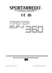
Parts name
Capacitor for FMI
Capacitor for FMO
Crankcase heater
Compressor motor
Connector (□ mark)
Drain motor
Fuse
Fan motor (Indoor unit)
Fan motor (Outdoor unit)
Float switch
Indication lamp (Green - Run)
Indication lamp (Yellow - Timer/Check)
Louver motor
Limit switch
Surge suppressor
Photo coupler
Switch (ON/OFF)
Changeover switch
Terminal block (嘷 mark)
Meaning of marks
Y / GN
RD
BK
RD
OR
OR
WH
BL
WH
Y / GN
BK
BK
WH
WH
CnD
23DH2
CnD
BK
BR
4
7
TB
1
2
3
4
5
TB
1
2
3
4
5
Parts name
BR
BL
BK
BK
RD
Thermistor
Thermistor
Thermistor
Transformer
Varistor
4-way valve solenoid
Thermostat (deicer)
Internal thermostat for CM
Internal thermostat for FMI
Internal thermostat for FMo
Magnetic contactor for CM
Relay for FMO
Relay for fan control
Auxiliary relay
High pressure switch (for control)
Terminal (F)
Connector
BR
BL
B
8
A
52C
20S
BK
7
RD
52Fo
8
52Xo
6
52XO
Mark
ThC
ThI-A
ThI-R
TrI
Val
20S
23DH
49C
49FI
49FO1,2
52C
52FO
52XO
X1~7
63H2
v
■
CnD
BK
BK
TB
Y / GN
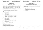
Outdoor Unit
BR
BL
BK
WH
RD
Y / GN
L1
Y / GN
BK
WH
WH
WH
WH
WH
PC
X6
Mark
BK
BL
BR
GR
OR
RD
WH
Y/GN
CnJ
3
X1
7
(49FI)
5
CnF1
WH
X7
CFI
CnF1
6
H UH
OR
L
FMI
8
X3
X4
Color
Black
Blue
Brown
Gray
Orange
Red
White
Yellow/Green
LM
CnJ
Color mark
14
X5
X1 X4 X7
X2 X5
X3 X6
Indoor Unit
CnI
FS
CnI
13
SW2
SW3
OFF
1 2 3 4
OFF
ON
1 2 3 4
ON
Test
BK
CnW1
CnQ
12V
BR CnW2
TrI
BK RD
BK
X
Y
Z
Thc
Remote
controller
RD WH BK
1
Wireless
remote
controller
Only case of FDT series.
Z
Y
X
BK LS
CnA
Receiver amp
Option
(3)
ThI–R
BK
RD
WH
BK
]
ThI–A
LED1
LED2
SW
(3)
(3)
CnS2
CnB
CnB2
CnN
BK
BK
XR5
XR3
XR1
BK
RD
RD
CnH2
BK BK
BK
BK
XR4
XR2
1 changes on
Printed wiring board
CnR
DM
CnR
4
X2
Val
220/240V
This diagram indicates the FDTN series. Section from
the FDT series.
10
9
2
1
[
BL
BL
BK
WH
BR
BR
WH
WH
BL
BL
BK
BK
BK
BK
BK
RD
RD
Y / GN
OR
OR
WH
WH
BK
BK
WH
WH
BR
BR
WH
WH
PC
GR
RD
RD
WH
CnT
CnH
CnN
CnL
CnV
CnS
1
Models
CnB
Power Source
3 Phase 380-415V 50Hz / 380V 60Hz
FDTN-H
FDTN408HES, 508HES
FDT408HES, 508HES
239
FDTN-H
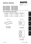
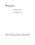
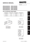
(6) Cautions for wireless remote conntroller operation
As wireless remote controller is operated by infrared rays as a signal, make sure to explain to customers the following matters
regarding the operating distance and protection from jamming.
¡ Operate it by directing the remote controller switch correctly to the receiver amp section.
¡ Operating distance is shown below, but it may become shorter or longer depending on circumstances.
¡ When its receiving section is directly under the sun or strong illumination, or covered by dust or behind an obstacle, the
operating distance may become shorter or it may not work.
¡ A hook for fixing the remote controller is provided for to keep the controller
Ceiling
from missing.
Scope possible
for receiving
(a) Operating distance of wireless remote controller
Operate it within the distance and angle shown in the sketch.
Floor
1) Standard receiving distance
CONDITION: 300 luxes at the receiving section (at an ordinary office where
Scope possible for receiving under illumination at
receiving section of 300 lux.
3m
2m
there is no ceiling light within one meter around the unit.
2)
1m
The receiving distance as viewd from the plane, and the relation between the illumination at the receiving section and re-
1m
2m
3m
4m
ceiving distance.
CONDITION:
The relation between illumination and receiving distance when
the remote controller is operated at the place one meter above
the floor with the ceiling 2.4 m high. When the illumination is
doubled, the receiving distance become 2.3.
Scope possible for receiving under illumination at
receiving section of 600 lux.
By switching the dip switch (SW3-3) on the indoor unit printed circuit board ("Specify the following switch number."), the operation
mode can be changed to the quiet mode (mild mode). Confirm at installation and change if necessary.
6.5.2 Installation of the wired remote controller (Optional parts)
(1) Selection of installation location
Following locations should be avoided:
(a) Where exposed to direct sunlight
(b) Near the heat source
(c) Highly humid area or where splashed with water
(d) Uneven installation surface
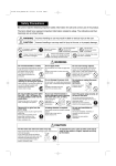
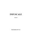
(2) Selection of installation location
Exposed installation
(a) Remove the remote controller case.
● Insert finger nails between the upper (white) and lower
(brown) cases and ply them to open.
Upper case (white)
(b) Remote controller cords can be taken out upward only as
shown below.
Top
(Cord take-out direction)
● Cut the remote controller lower case off at the top and thin
section with a nipper, knife or other and remove burrs from
the cut with a file or other.
(c) Secure the remote controller lower case on the wall with 2
pieces of wood-screws.
Top
Lower case
Lower case (brown)
Bottom
(d) Connect the remote controller cords with the terminal block.
Make sure to align the terminal numbers on the indoor unit
and the remote controller. Polarities are specified on the terminal block so that the unit will not be operated if the cords
are connected improperly.
Terminals: (X) red wire, (Y) white wire, (Z) black wire
260
FDTN-H
1) Set necessary functions in accordance with the model of indoor
5) Couple the upper case with the lower case as it was to
unit.
finish up the installation.
Refer to (c) for the setting of functions.
2) Couple the upper case with the lower case as they were.
3) Secure the remote controller cords on the wall or other using cord
clamps.
Embedded installation
1) Have a JIS box and remote controller cords (use shielding wires
or twisted pair wires for extension) embedded in the wall in
M4 round head screw x 2 pieces
(Provided by customer)
advance.
Cautions for extension of remote controller cords
Remote controller cords
● Make sure to use shielding wires only.
• All models: 0.3 mm2 x 3 core wires [MVVS3C,
JIS box
(Provided by customer)
products of Keihan Cables]
Note (1) When the extension distance exceeds 100 m, change the
wire size as follows:
100 ~ 200 m ... 0.50 mm2 ⳯ 3 core wires
Adequate JIS box
~ 300 m ... 0.75 mm2 ⳯ 3 core wires
● JIS C 8336 Single switch box (without cover)
~ 400 m ... 1.25 mm2 ⳯ 3 core wires
● JIS C 8336 Medium size square outlet box and two-switch cover
~ 600 m ... 2.00 mm2 ⳯ 3 core wires
with paint margin
● Make sure to ground one side only of the
2) Remove the upper case from the remote controller.
shielding wire.
3) Secure the remote controller body on the JIS box with 2 pieces of
M4 round head screw (provided by customer).
4) Connect remote controller cords with the remote controller.
(Refer to the section regarding the exposed installation.)
6.5.3
Installation of outdoor unit
OWARNING
BE SURE TO READ THESE INSTRUCTIONS CAREFULLY BEFORE BEGINNING INSTALLATION. FAILURE TO FOLLOW THESE INSTRUCTIONS COULD
CAUSE SERIOUS INJURY OR DEATH, EQUIPMENT MALFUNCTION AND/
OR PROPERTY DAMAGE.
Models : FDC208~508 series
(1) Installation
(a) Accessories
Confirm accessories shown below are attached in the bag with this installation manual.
1)
“Edging” for protection of electric wires from opening edge.
(b) Selection of installation location
Select the installation location after obtaining the approval of customer.
1)
The place where the foundation can bear the weight of Outdoor unit.
2)
The place where there is no concern about leakage of combustible gas.
3)
The place where it is not stuffy.
4)
The place where free from thermal radiation of other thermal source.
5)
The place where flow of drain is allowed.
6)
The place where noise and hot air blast do not trouble neighboring houses.
7)
The place where there is no obstruction of wind at the intake air port and discharge air port.
261
FDTN-H
(5) Electrical wiring
™ This air conditioning system should be notificated to supply authority before connection to power supply system.
(a) Selection of size of power supply and interconnecting wires.
OIMPORTANT
● Electric wiring work should be conducted only by authorized personnel.
● Use copper conductor only.
● Power source wires and Interconnecting wires shall not be lighter than polychloroprene
sheathed flexible cord (design HO5RN-F IEC 57).
● Do not connect more than three wires to the terminal block.
● Use round type crimped terminal lugs with insulated grip on the end of the wires.
¡ Select wire sizes and circuit protection from Table 2.
Table 2 ( This table shows 20m length wires with less than 2% voltage drop. )
Item
Circuit breaker
Phase
Model
FDC208H(C) type
FDC258H(C) type
FDC258CEP3
FDC308HEN3
FDC308HES3
FDC408H type
FDC508H type
(b)
Over-current protector
rated capacity (A)
20
1
30
30
15
3
20
Power source
wires
(minimum)
Interconnecting
and grounding
wires (minimum)
ø 2.0 mm
5.5mm2
ø 1.6
ø 2.0 mm
5.5mm2
Wiring connection.
1) Connect the same terminal number between the Indoor unit and Outdoor unit as shown in the following diagram.
2) Make wiring to supply to the Outdoor unit, so that the power for the Indoor unit is supplied by 1 and 2 terminals.
3) Secure the wiring with wiring clamp so that no external force is transmitted to the connecting portion of terminal.
4)
1
Switch breaker
(A)
There is a ground (Earth) terminal in the control box.
1 phase model
Note (1) The diagram below is for
models equipped with
heat pumps. Cooling
only units do not have
TB (4), (5).
Outdoor
unit
2
3 phase model
Note (1) The diagram below is for
models equipped with
heat pumps. Cooling
only units do not have
TB (4), (5).
Power source and ground terminal block
Wiring clamp
Circuit breaker
Earth leakage Indoor
unit
breaker
™ Secure the wiring so that no external force
is applied to the connecting portion of
terminal.
HIGH VOLTAGE
HIGH VOLTAGE
™ Same as the refrigerant piping, 4
directions are allowed, which are right,
front, rear and down.
Interconnecting
wires
Interconnecting
wires
Circuit breaker Indoor
unit
Earth leakage
breaker
Outdoor
unit
Take out direction of wiring
(6) Test run
OCAUTION
Wiring diagram
™ Wiring diagram is fixed at the backside
of service panel.
THIS UNIT WILL BE STARTED INSTANTLY WITHOUT "ON" OPERATION WHEN ELECTRIC
POWER IS SUPPLIED.
BE SURE TO EXECUTE "OFF" OPERATION BEFORE ELECTRIC POWER IS
DISCONNECTED FOR SERVICING.
● This unit has a function of automatic restart system after recovering power stoppage.
DO NOT LEAVE OUTDOOR UNIT WITH THE SERVICE PANEL OPENED.
● When the service panel is removed, high voltage portion and high temperature areas are
exposed.
OIMPORTANT
● Check that the service valves are fully opened without fail before operation.
● Turn on the power for over 12 hours to energize the crankcase heater in advance of
operation.
● Wait more than 3 minutes to restart the unit after stop.
¡ Run the unit continuously for about 30 minutes, and check the following.
™ Suction pressure at check joint on the compressor suction pipe.
™ Discharge pressure at check joint on the compressor discharge pipe (for Heat pump model), or at check joint of service
valve for gas pipe (for cooling only model).
™ Temperature difference between return air and supply air for Indoor unit.
¡ Refer to “Check Indicator Table” on wiring diagram of Outdoor unit or “User’s manual” of Indoor unit for diagnosis of operation
266 failure.