1
SUMMIT REGULATORY UTILITY (SRU) GUIDE
Windows CE, Windows Mobile, and Window XP
Version 3.05.0.11
Americas: +1-800-492-2320 Option 2
Europe: +44-1628-858-940
Hong Kong: +852 2923 0610
www.lairdtech.com/wireless
Summit Regulatory Utility Guide
Windows CE, Windows Mobile, and Windows XP
CONTENTS
Summit Radios ............................................................................................................................................. 3
Summit Software ......................................................................................................................................... 4
Overview .................................................................................................................................................. 4
Initiating the SRU.................................................................................................................................. 5
Installing Summit Software and Summit Radios ......................................................................................... 5
Regulatory Compliance ......................................................................................................................... 5
Loading SRU............................................................................................................................................. 5
Removing the SRU from the Device........................................................................................................... 5
Using the Summit Regulatory Utility .............................................................................................................. 5
Running Your First Test............................................................................................................................. 6
Running Subsequent Tests ........................................................................................................................ 6
Notes on SRU ........................................................................................................................................... 7
Test and Measurement Methodology Conducted Transmit Power Assessment of RF Devices ......................... 8
Scope ....................................................................................................................................................... 8
Objective .................................................................................................................................................. 8
RF Test Equipment: ................................................................................................................................... 8
Simplified Bench Testing Diagram ............................................................................................................. 8
Power Meter Setup................................................................................................................................... 9
Spectrum Analyzer Initialization Setup (see DTS section for additional settings) ........................................ 10
Maximum Power Output - FCC Part 15.247(b) Digital Transmission Systems (DTS) .................................. 10
y DTS (RSS) ............................................................................................................................................. 12
z DTS (Other).......................................................................................................................................... 13
References ............................................................................................................................................. 13
Spectrum Analyzer Bin Integration Method ................................................................................................. 13
Procedure1.............................................................................................................................................. 13
Americas: +1-800-492-2320 Option 2
Europe: +44-1628-858-940
Hong Kong: +852 2923 0610
www.lairdtech.com/wireless
2
CONN-SRU_v3_5_0_11
Summit Regulatory Utility Guide
Windows CE, Windows Mobile, and Windows XP
LAIRD WI-FI RADIOS
Thank you for choosing one of the following Laird radio modules or cards:
802.11g radios (support 802.11b and 802.11g)
CF10G
Compact flash (CF) module with antenna connectors
CF20G or CF22G
CF card with integrated antennas
PC10G
PC20G or PC22G
PCMCIA module with antenna connectors
PCMCIA card with integrated antennas
MCF10G
MSD10G
Miniature CF module with antenna connectors
Miniature SDIO module with antenna connectors
802.11a/g radios (support 802.11a, 802.11b, and 802.11g)
CF10AG
CF module with antenna connectors
CF22AG
PC10AG
CF card with integrated antennas
PCMCIA module with antenna connectors
PC22G
PCMCIA card with integrated antennas
MCF10AG
MSD10AG and MSD30AG
SSD30AG
Miniature CF module with antenna connectors
Miniature SDIO module with antenna connectors
Miniature SDIO module
802.11n radios (support 802.11a, 802.11b, 802.11g, and 802.11n)
PE15N
PCIe (Express) mini card with antenna connectors
EC15N
ExpressCard (EC) with antenna connectors
EC25N
ExpressCard (EC) with integrated antennas
802.11n Wi-Fi and BT modules - 40 series
MSD40NBT
SSD40NBT
Enterprise-grade dual-band 802.11n and Bluetooth in a pluggable module
Enterprise-grade dual-band 802.11n and Bluetooth in a SiP module
WB40NBT
Complete wireless communication subsystem
Each Laird radio enables a computing device to communicate to a computing network using the IEEE
802.11a, 802.11b, 802.11g, and/or 802.11n protocols. The hardware components and software for all
related Laird radios are the same. For example:
The 20G version is a 10G version with integrated antennas.
The PCMCIA version is a CF version in a specially designed CF-to-PCMCIA carrier.
The miniature CF version is essentially the CF version with a different layout and a different (Molex)
connector.
For an overview of all Laird products, go to www.lairdtech.com/wireless.
Americas: +1-800-492-2320 Option 2
Europe: +44-1628-858-940
Hong Kong: +852 2923 0610
www.lairdtech.com/wireless
3
CONN-SRU_v3_5_0_11
Summit Regulatory Utility Guide
Windows CE, Windows Mobile, and Windows XP
LAIRD SOFTWARE
Overview
Laird software is a set of integrated components that includes:
A device driver which controls the operation of the radio on the device
An 802.1X security supplicant which handles authentication and encryption key management
Utilities, including the administrative application called the Summit Client Utility (SCU)
A software developer’s kit (SDK) for these utilities
Laird supports its software on the following operating systems:
Windows Embedded CE 6.0 (R1, R2, and R3) and 5.0
Windows Mobile 6.5, 6.1, 6, and 5.0
Windows XP Professional and Embedded
Windows 7 (SDC-PE15N, SDC-EC15N, and SDC-EC25N devices only)
Note: The SDC-PE15N, SDC-EC15N, and the SDC-EC25N radios only use the Windows XP and Windows 7
operating systems.
SCU is designed for end users and administrators of mobile devices that use a Laird radio module. Although
SCU provides a GUI for access to all of its functions, access to these functions is also available through the
SDK on which SCU relies. A Laird customer can use the SDK to manage the radio from another utility, such as
one that the customer provides with its mobile devices.
Using the SCU, an administrator can configure the radio and security settings in a configuration profile
(config). For a list of configuration settings, see the Laird User’s Guide. You can access Laird documentation
from the Documentation page of the Laird website at:
http://www.summitdatacom.com/documentation.htm.
An administrator also can use the SCU to define a set of global settings which apply to all configs and to the
SCU. For a list of global settings that can be configured using the SCU, see the Laird User’s Guide.
The Summit Regulatory Utility (SRU) enables you to conduct regulatory domain tests that require continuous
receive, continuous transmit, and continuous wave (CW) frequency.
Note: Both the Summit Regulatory Utility (SRU) and the Summit Manufacturing Utility (SMU) are required for
regulatory testing. The SMU allows you to make necessary adjustments to your radio including
maximum transmit power levels. The SRU places the Laird radio into special test modes.
Note: CW frequency is not available for the SDC-PE15N radio.
Laird offers SRU only to its direct customers:
Device manufacturers that use embedded Laird radios in their devices or offer Laird radios as device
options.
Value-added distributors that must configure Laird radios for resellers and end-customers.
This guide is for SRU V3.03 running on Windows CE, Windows Mobile, or Windows XP.
Americas: +1-800-492-2320 Option 2
Europe: +44-1628-858-940
Hong Kong: +852 2923 0610
www.lairdtech.com/wireless
4
CONN-SRU_v3_5_0_11
Summit Regulatory Utility Guide
Windows CE, Windows Mobile, and Windows XP
Initiating the SRU
To use SRU in a computing device, you first must perform the following steps:
Step 1:
Note:
Install Laird software on a mobile computing device that runs a supported operating system.
Prior to installing the radio, uninstall any Laird or Broadcom radio drivers currently installed on your
computer.
Step 2:
Install the Laird radio on the device.
Step 3:
Load SRU on the device.
It is recommended that you complete the steps in the order shown above. If you insert the radio in your
device before you install the software, then the operating system flags the radio as unknown and displays the
“Found New Hardware Wizard” screen; you must click Cancel to cancel the Hardware Wizard.
Once you have finished using SRU, you must remove SRU from the device. SRU is for the exclusive use of
those Laird customers to which Laird makes the SRU available. Those customers are not permitted to
redistribute SRU.
Installing Laird Software and Laird Radios
Note: Refer to the Laird Installation Guide for detailed information on installing Laird software and Laird
radios. This installation guide is available from the Laird website Documentation page:
http://www.summitdatacom.com/documentation.htm
Regulatory Compliance
To comply with FCC RF exposure compliance requirements, each antenna used with a Laird radio module
must be installed with a separation distance of at least 20 cm from all persons and must not be co-located or
operating in conjunction with any other antenna or transmitter.
The user’s manual for the device that embeds or otherwise uses a Laird radio should not provide information
on how to install a radio module within a device or remove an installed radio module from a device.
Each device is labeled with all applicable regulatory information in a manner that’s compliant with all
regulatory standards. Regulatory operational requirements are included with this document and are to be
incorporated into the operating manual of any device into which the Laird radio is installed. For complete
regulatory information, refer to the “Hardware Integration Guide” for the applicable radio.
Loading SRU
Identify the appropriate sru.exe file for the operating system and processor of your device. Download the file
and copy it to your mobile device using a supported file transfer mechanism.
Removing the SRU from the Device
SRU is designed exclusively for Laird direct customers and not for device end-users or administrators. Once
you have used SRU to configure radio settings on a device that will be used by someone in another
organization, you must remove SRU from the device. To do so, simply erase the file sru.exe.
USING THE SUMMIT REGULATORY UTILITY
Americas: +1-800-492-2320 Option 2
Europe: +44-1628-858-940
Hong Kong: +852 2923 0610
www.lairdtech.com/wireless
5
CONN-SRU_v3_5_0_11
Summit Regulatory Utility Guide
Windows CE, Windows Mobile, and Windows XP
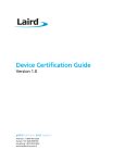
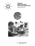
SRU performs tests for regulatory
domain exercises. These tests
require continuous transmit,
continuous receive, and continuous
wave (CW) frequency.
To run SRU, use File Explorer or
Windows Explorer to locate the
SRU.exe file. Tap the file to execute
it. The screen displayed at the right
displays. Use the Test drop-down
menu to select the applicable test:
Tx – Continuous transmit test
Rx – Continuous receive test
Freq – CW frequency test
Note:
Continuous wave (CW) frequency is not available for the SDC-PE15N.
Off – Device is out of testing mode
Use other drop-down menu to configure the selected test, and then tap Commit Changes to save your test
configuration.
Note:
If you select N (20 MHz), you must use MCS rates. Select the MCS rates (rather than Mbps) from the
Connection Rate drop-down menu. If you select Mbps, you will be prompted to select MCS rates
instead.
Note:
For 40 MHz, diversity must be OFF. For 20 MHz, diversity is ON. You can set Tx Diversity parameters
from the SCU global settings tab.
Running Your First Test
When you configure your first test and tap Commit Changes, SRU displays the following message: “Power
Cycle Device to put into test mode and keep this program running”. The power cycle is required because the
Laird driver checks for test mode only at device power-up. Once you power-cycle the device and tap OK on
the first message box, SRU displays a second message: “Click Ok to continue once the power cycle is
complete”. Once you tap OK, the test begins.
Your first test should continue running until you start a new test or take the device out of test mode. You
should be able to start a new test by configuring the test on the SRU window and tapping Commit Changes.
Note:
Tapping Commit Changes while a test is running can lead to unpredictable results, such as the
display of the message “Failed to stop Tx!!!!”. See “Running Subsequent Tests” following this
section for a more reliable approach for running multiple tests in succession.
Running Subsequent Tests
Once SRU is running a test, the most reliable way to start a new test is to do the following:
Step 1:
Take the device out of test mode by selecting Off for the test and tapping Commit Changes.
Step 2:
Power-cycle the device.
Americas: +1-800-492-2320 Option 2
Europe: +44-1628-858-940
Hong Kong: +852 2923 0610
www.lairdtech.com/wireless
6
CONN-SRU_v3_5_0_11
Summit Regulatory Utility Guide
Windows CE, Windows Mobile, and Windows XP
Step 3:
Configure the new test.
Step 4:
Tap Commit Changes.
Step 5:
Power-cycle the device (again).
Step 6:
Run the new test by selecting the type of test (Tx, Rx, or Freq) and tapping Commit Changes
(again).
Notes on SRU
If SCU is active while SRU is running tests, then SCU displays a status of “FCC Test Mode”.
SRU assumes that the card has been configured for the correct regulatory domain and maximum transmit
settings. For example, if you select channel 12 but your radio is configured for the FCC domain, then the test
won’t work; your radio must be configured for ETSI or TELEC to use channel 12.
SRU uses the Laird software developer’s kit (SDK) for its operations. A brief synopsis of what SRU does is
shown below:
Call the FirstFCCtest routine
Set the registry for static IP address 10.0.0.255, gateway 10.0.0.255, mask 255.255.0.0
Prompt for a power cycle and wait until the power cycle is complete
If (test = continuous_Tx), then call the Start testTxData routine to get data transmitting
loop {
Get next test from user
If (previous test = Continuous_Tx), then call the Stop testTxdata routine
Call the NextFCCtest routine
If (test = continuous_Tx), then call the Start testTxData routine to get data transmitting
} until exit
Upon exit, call the nextFCCtest routine with FCCTEST_OFF
Restore dynamic IP in registry
Power cycle
Reset unit
SRU obtains eight packets of data from the SDK. The driver recycles the same eight packets over and over as
fast as possible.
Americas: +1-800-492-2320 Option 2
Europe: +44-1628-858-940
Hong Kong: +852 2923 0610
www.lairdtech.com/wireless
7
CONN-SRU_v3_5_0_11
Summit Regulatory Utility Guide
Windows CE, Windows Mobile, and Windows XP
TEST AND MEASUREMENT METHODOLOGY CONDUCTED TRANSMIT POWER
ASSESSMENT OF RF DEVICES
Scope
This document describes an acceptable RF pulsed power testing methodology for measurement of conducted
transmit power on modular transceiver devices with external RF antenna connectors.
Objective
This testing methodology is intended to provide a redundant RF pulsed power measurement capability at SDC
by making substantial use of the on-hand RF test equipment.
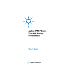
RF Test Equipment:
Agilent E4416A Single Channel Power Meter and E9323A Sensor Model or equivalent.
IFR (AeroFlex) 2394A Spectrum Analyzer or equivalent.
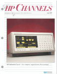
Simplified Bench Testing Diagram
Note: The important concept for this setup is the sharing of the power meter triggering and time gating
control mechanisms with the spectrum analyzer such that power measurement events for both the
power meter and the spectrum analyzer occur synchronously (simultaneously).
Americas: +1-800-492-2320 Option 2
Europe: +44-1628-858-940
Hong Kong: +852 2923 0610
www.lairdtech.com/wireless
8
CONN-SRU_v3_5_0_11
Summit Regulatory Utility Guide
Windows CE, Windows Mobile, and Windows XP
Power Meter Setup
Step 1:
Follow the user manual instructions to warm up, preset, and calibrate/zero the power meter.
The power sensor data should already be stored in non-volatile memory.
Step 2:
Use the Channel button to display the Channel Setup. Select the (test) Frequency option.
Use the Change option and the up/down arrows to set the Frequency in GHz (i.e. UUT
channel freq.).
Step 3:
Use the Channel button to display the Channel Setup. Select Video Ave. and select Change
to turn the Video Ave. ON. Move the marker to the number of averaging samples and use
the Change option and the up/down arrows to set the Video Ave to 128 (i.e. UUT channel
freq.).
Step 4:
Use the Channel button to display the Channel Setup. Select Video B/W and select Change
to turn the Video B/W to MED.
Step 5:
Use the Channel button and the Gates option to display the Gates menu. Use the up/down
arrows and the Change option to set (only) Gate1 Start to 50us and the Length to 200us.
Note:
A power measurement interval such as 200us is sufficient for statistical coverage of the modulated
data symbols and also limited to not exceed the shortest transmit pulse length.
Step 6:
Use the Channel button and the Trace Setup option to display the Channel Trace setup. Use
the up/down arrows and the Change option to set Length to 250us (50us+200us).
Step 7:
Use the Trigger button and select Acqn FreeRun (default) to display the Acqn menu. Select
ContTrig.
Step 8:
Use the Trigger button and select Settings to display the continuous trigger Settings menu.
Use the Mode AutoLvl (default) option and select Norm.
Step 9:
Use the Trigger button and select Settings again to display the continuous trigger Settings
menu. Select Level 0.0dBm (default) and use the up/down arrows to set the Trigger Level
(threshold) to 0 dBm.
Step 10:
Use the Trigger button and the More button (1OF2) to display advance trigger settings.
Select Output to turn the external trigger output to ON.
Step 11:
Use the Meas. Display button and select Display Type to display the Display Type menu.
Select Dual Numeric for the upper measurement window.
Step 12:
Use the Meas. Setup button and select Relative/Offset to display the Rel./Offset menu. Select
Offset to enter the total RF cable/splitter insertion loss between the UUT RF connectors and
power sensor RF input connector. A typical Figure 1 value may be 4 dB nominal.
Note:
The insertion loss value may be slightly different between 2 GHz and 5 GHz bands (i.e., 1dB).
Step 13:
Use the Display UP/DOWN arrows located left of the panel LCD display to shift the (large)
pointer arrow from upper to lower numeric position in the upper measurement window.
Americas: +1-800-492-2320 Option 2
Europe: +44-1628-858-940
Hong Kong: +852 2923 0610
www.lairdtech.com/wireless
9
CONN-SRU_v3_5_0_11
Summit Regulatory Utility Guide
Windows CE, Windows Mobile, and Windows XP
Step 14:
Use the Meas. Setup button and select Meas. Select to display the Meas. Sel. menu. Use the
Change option to change from Ave to Peak measurements (feed).
Step 15:
Use the Meas. Setup button and select Relative/Offset to display the Rel./Offset menu. Select
Offset to enter the total RF cable/splitter insertion loss between the UUT RF connectors and
power sensor RF input connector. A typical Figure 1 value may be 4 dB nominal.
Step 16:
Use the Display UP/DOWN arrows located left of the LCD display to shift (highlight) from
upper to lower measurement window.
Step 17:
Use the Meas. Setup button and select Relative/Offset to display the Rel./Offset menu. Select
Offset to enter the total RF cable/splitter insertion loss between the UUT RF connectors and
power sensor RF input connector. A typical Figure 1 value may be 4 dB nominal.
Step 18:
Use the Meas. Display button and select Display Type to display the Display Type menu.
Select Trace.
Spectrum Analyzer Initialization Setup (see DTS section for additional settings)
Follow the user manual instructions to warm up and preset. Use the Freq button to set the Frequency in GHz
(UUT channel freq.).
Step 1:
Use the Span button to set the measurement span to 50 MHz.
Step 2:
Use the Amplitude button and then use the Function (F7) More.. button to display advanced
options. Use the Function (F2) Ref. Offset button to set the insertion loss between the UUT
and spectrum analyzer RF connector. A typical Figure 1 value may be 4 dB nominal. The F2
button must be pressed (again) after entering the dB value to turn the offset on.
Step 3:
Use the Amplitude button and then use the Function (F2) Atten.. button; set to Manual and
20dB.
Step 4:
Use the Amplitude button and then use the Function (F1) Ref. Level button and set to 10
dBm.
Step 5:
Use the Trig button and then use the Function (F3) Source button to display the Trig menu.
Use the Function (F4) External button to set the spectrum analyzer to accept external triggers
from the power meter (TTL).
Step 6:
Use the Trig button and then use the Function (F5) Time Gate button to turn the time gate
to ON.
Note: The F5 button must be pressed TWICE to change from OFF to ON.
Maximum Power Output - FCC Part 15.247(b)
Digital Transmission Systems (DTS)
Power Option 2 [Power Output Measurement allowed per Section 15.247(b)(3)].
Additional Spectrum Analyzer Setup Requirements (EBW > largest RBW, Method #3)
- RBW – 1 MHz
- EBW – 22 MHz
- Span – 50 MHz
- Sweep Time – 20ms
Americas: +1-800-492-2320 Option 2
Europe: +44-1628-858-940
Hong Kong: +852 2923 0610
www.lairdtech.com/wireless
10
CONN-SRU_v3_5_0_11
Summit Regulatory Utility Guide
Windows CE, Windows Mobile, and Windows XP
VBW – 1 MHz (max. allowable on SA)
Detector – SMPL and POS (number of points / span = unknown)
Time Gate – External Level Length =200us (see power meter setup)
Use SA Power Integration Measurement Capability
Use Channel Power (F3)
Use Max Hold (F3)
Display Amplitude Mode – Log (no linear mode Measurement Capability, Manual Integration of Bins
required).
- Max. Hold Duration
=60 seconds, min.
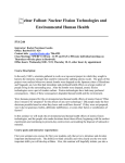
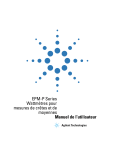
Measurement Results, Sample
- FCC 1Mb/s Data File
-
Plot a) Sample
Plot b) POS
Americas: +1-800-492-2320 Option 2
Europe: +44-1628-858-940
Hong Kong: +852 2923 0610
www.lairdtech.com/wireless
11
CONN-SRU_v3_5_0_11
Summit Regulatory Utility Guide
Windows CE, Windows Mobile, and Windows XP
FCC 6 Mb/s Data File
Plot A) POS
Plot B) Sample
y DTS (RSS)
Americas: +1-800-492-2320 Option 2
Europe: +44-1628-858-940
Hong Kong: +852 2923 0610
www.lairdtech.com/wireless
12
CONN-SRU_v3_5_0_11
Summit Regulatory Utility Guide
Windows CE, Windows Mobile, and Windows XP
z DTS (Other)
References
SPECTRUM ANALYZER BIN INTEGRATION METHOD
Procedure1
1. Set the SA RBW = 1 MHz
2. Set the SA Span = 50 MHz (EBW-26 ~ 22 or 44 MHz)
3. Set the SA Sweep = Auto (20ms typical)
Note:
The transmit pulse duration may range from 200us to 2ms (verify), therefore, the SA sweep time
(20ms) is greater than T (200us to 2ms). Also, since EWB > RBW max., use Method #3 (video
averaging3 with max. hold, integrate across EWB).
4. Set the trigger source = Free Run
5. Set the SA VBW = 1MHZ (T =200us or greater pulse length, min.)
6. Set the SA Display Mode = Linear (adjustment of the Reference Level may be required)
Note:
7.
8.
9.
10.
According to the spectrum analyzer operating manual, the number of displayed data points equals
500. With a 50 MHz SA Span, the number of points per RBW equals 10.
Set the SA Detection Mode = Sample (100 kHz < 500 kHz or 1/10 < .5 RBW)
Set the SA Trace Mode = Max. Hold
Allow the maximum hold measurement to run for 60 seconds.
Compute power by integration across the EBW or use the Marker Peak function to find the highest Peak
and compute a correction factor of 10*log(EBW/Mhz).
Caution:
For non-rectangular pulse spectral displays, the correction factor method will likely cause the
measured power result to error high (e.g. greater than actual). This will also be the case if the
amplitude of an individual bin is substantially greater than typical bin peaks at the top of the EBW
(e.g. may be an unfavorable estimate).
11. Use of the SA measurement capability is allowed or a linear sum of 1 MHz bin powers is allowed
provided that the bin power is the result of averaging the (10) bin samples in each 1 MHz RBW (post max.
hold averaging). The SA Marker function may be helpful in obtaining the individual sample values per 1
MHz bin.
12. Bin Sum Equation:
P = 10 *log[SUMBINS[AverageLinearBinPower]]
P = 10 *log[SUMBINS[(1/n) *SUMSMPLS[1:n][10^(P(i)/10)]]
References:
1
http://fjallfoss.fcc.gov/edocs_public/attachmatch/DA-02-2138A1.pdf
2
http://www.mwrf.com/Articles/Index.cfm?Ad=1&ArticleID=14305
Americas: +1-800-492-2320 Option 2
Europe: +44-1628-858-940
Hong Kong: +852 2923 0610
www.lairdtech.com/wireless
13
CONN-SRU_v3_5_0_11