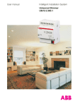
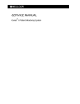
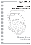
1
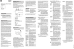
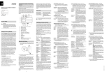
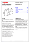
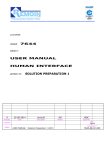
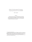
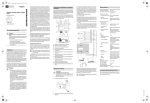
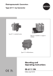
KNX DALI gateway REG-K/1/16(64)/64MTN680191© Merten2009V6801-561-0107/10
Connections, displays and operating
elements
KNX DALI gateway REG-K/1/16(64)/64
Operating instructions
The appliance connections and the learning button and
programming LED elements required for KNX commissioning can only be accessed in the distribution board
when the cover is removed.
The keys required for DALI commissioning and parameterisation (SCROLL, Prg/Set, ESC) can only be operated
when the distribution board's cover is closed. Similarly,
the 2-row display and the control LEDs (PWR and ERR)
can only be seen when the distribution board's cover is
closed.
F
Art. no. MTN680191
G H
M N
L
To connect the KNX cable, a standard bus terminal is
plugged into the corresponding terminal receiver on the
device. Double basic insulation between the KNX installation and the mains voltage must be ensured. For this
purpose, the cores of the KNX cable must additionally be
insulated with the enclosed shrink hose. When connection is complete and the supply voltage is activated, the
product designation and firmware version will be shown
in the display.
Status LED
PWR LED flashes
ERR LED lights up
ERR LED lights up
despite KNX voltage
Device is ready for operation
Commissioning without KNX
Possible short circuit
within the DALI segment.
Check the DALI segment's wiring!
K
¼
DANGER
Risk of fatal injury due to electrical current
All work on the device must only be carried out by
trained and skilled electricians. Observe the
country-specific regulations as well as the valid
KNX guidelines.
Getting to know the Gateway
The KNX DALI gateway REG-K/1/16(64)/64 (referred to
below as the gateway) connects the cross-function KNX
bus with the DALI bus designed exclusively for lighting
control. Luminaires with cost-effective digital DALI electronic ballasts can therefore be integrated into a KNX
complete system in the form of a subsystem and operated by a wide range of available KNX devices.
The gateway serves as the DALI master and power supply for the connected electronic ballasts. Up to a maximum of 64 electronic ballasts in a total of 16 groups can
be switched, dimmed or set to a defined value. The current light value or the error status of each group (luminaire or electronic ballast errors within the group) can be
made available for a visualisation via KNX. In addition,
the 64 electronic ballasts can be individually activated
via KNX or via KNX group addresses. In the case of individual activation, one programmable object is available
per electronic ballast.
One error status is available for each electronic ballast.
Lamps and electronic ballast errors can thus be precisely located. Total activation of all connected electronic ballasts via broadcast (without requiring DALI
commissioning) can also be carried out via three objects. Additionally, up to 16 lightscenes can be programmed and called up from the individual groups.
Scene activation is effected via a 1-byte object.
DALI commissioning and configuration can be performed as follows:
1. via the device
2. via a software tool (free of charge)
3. via the integrated web server
4. via a portable web panel or a PDA
5. via two binary inputs, e.g. for connecting push-buttons
to the device (building site operation).
It is installed on a DIN-rail TH 35 according to EN 60715,
with the bus connection made via a bus connecting terminal.
A data rail is not required.
Network, DALI and push-button lines are connected using screw terminals on the device.
|
I
If the programming mode is active, a possible parameter
or setting can be changed using the SCROLL button.
Briefly pressing the Prg/Set button again completes the
process. The set parameter is saved or the corresponding process is activated.
DALI CONTROL submenu - level 2
J
For your safety
To do this, actuate the Prg/Set button for longer than 2s..
If the respective function is in programming mode, a ->
symbol appears in the display.
The pin assignment shown on the housing must
be observed!
1 Press the Prg/Set key: Switches from the DALI
CONTROL main menu to the LANGUAGE submenu.
LANGUAGE Display: current display language.
GERMAN
Long actuation of the Prg/Set key:
Switches to the programming mode.
Language selection (GERMAN, ENGLISH, FRENCH, SPANISH,
SWEDISH) using the SCROLL button.
B
C D
Operating and menue structure
E
A
Ethernet connection (RJ-45 socket)
B
KNX bus terminal
C
Programming LED
D
Programming button
E
Mains connection
F
DALI output terminal
G
Connection for 1st floating key
H
Connection for 2nd floating key
I
Display
J
SCROLL key
K
Prg/Set key
L
ESC key
M
PWR LED (green): Operating display
N
ERR LED (red): Error display
The connected DALI segment can be commissioned
and DALI parameters can be set and altered entirely using the three operator buttons (SCROLL, Set/PRG, ESC)
and the 2x12 row display on the front face of the device.
The operation concept is menu-based. Up to two lower
levels can be selected for each menu item. The respective menu item is shown in the display. Navigation within
the menu is as follows:
SCROLL key: Short push-button action activates the
next menu item within a level.
Prg/Set key: Short push-button action activates the respective sub-level.
ESC key: Short push-button action to leave the selected
level and return to the level above.
1 Press the Prg/Set key: Switches from the IP ADDRESS main menu to the submenu.
IP: 192.168. Displays the IP address currently set in
004.101
the ETS or assigned by a DHCP server
in the IP network. The setting cannot be
changed on the device. Setting is performed via the ETS or via DHCP.
REINSTALLATION submenu - level 2
1 Press the Prg/Set key: Switches from the INSTALLATION main menu to the SEARCH EBs submenu
via PROG MODE.
SEARCH
EBs via
PROG
MODE
Main menu - level 1
The main menu (level 1) has the following structure:
Mounting the Gateway
1 Insert the gateway into the DIN rail from above and
slide downwards. Press from underneath and hook
onto the rail
1
2
3
2 Connect the connecting cable for the DALI bus to
the upper left terminal.
The DALI control cables can be guided into a 5-core cable together with the power line (basic insulation sufficient), according to IEC90929. Clear labelling must be
guaranteed, however. A maximum line length of 300 m
for the entire DALI installation of a segment must not be
exceeded (recommended cross-section 1.5mm2).
After connecting the DALI cable, the two external pushbuttons can be fitted according to the connection diagram, if necessary. The push-button inputs are passive,
which means that an auxiliary voltage of AC 8–26 V or
DC 9–32 V is required.
3 Connect the mains voltage (according to the connection order shown on the housing) to the lower
right terminal.
DALI CONTROL Displays the product designation and
SC64IP,V.2.0
firmware version. Display language
setting.
IP ADDRESS
Displays the IP address set in the ETS
or assigned by the DHCP server.
NEW
Resets the connected DALI devices
INSTALLATION and starts the automatic search run for
electronic ballasts.
REINSTALLA- Starts the automatic search run and
TION
configuration adjustment, where required.
GROUP ASAssignment of the electronic ballasts
SIGNMENT
found to desired DALI groups.
GROUP PASetting/modifying the parameters of
RAMETERS
the individual groups.
SCENE
Assignment of DALI scenes to the deASSIGNMENT sired associated groups.
GROUP
Switching the entire installation
TEST
(broadcast) and individual channels
for test purposes.
SCENE
Retrieves the individual programmed
TEST
scenes for test purposes.
SYSTEM
Present system errors can be reTEST
trieved individually.
FUNCTION
Setting the function of the floating
INPUT B1
push-button input B1.
FUNCTION
Setting the function of the floating
INPUT B2
push-button input B2.
If a process is activated in a lower level or if a parameter
is altered, the programming mode must be switched to at
the selection position.
After the entire process has been completed (verification and search):
The number of deleted and newly found
EBs is displayed (deleted devices/new
devices, from left to right).
2 Press ESC key (or automatically after approx. 30 s):
Returns to the level above.
GROUP ASSIGNMENT submenu - level 2 and 3
1 Press the Prg/Set key: Switches from the GROUP
ASSIGNMENT main menu to the submenu. Within
this menu, the individual EBs found during the
search process can be assigned to the 16 DALI
groups or existing assignments can be altered.
GROUP ASSIGNMENT
EB no.:12
GROUP: --
2 Press the Prg/Set key: set parameterisation is confirmed and saved and the display works in the corresponding language.
IP ADDRESS submenu - level 2
A
DEL./NEW
EBs: 3/1
FOUND
EBs: 47
Long actuation of the Prg/Set key: Switches to the programming mode.
Then press the Prg/Set key briefly: Starts
the initialisation and search process. All of
the electronic ballasts connected to the
DALI segment are automatically reset and
any previously set parameters/group assignments are deleted. The connected
EBs are then searched for via their randomly generated long address and automatically recognised in ascending order.
The search process lasts several minutes
(depending on the number of connected
EBs).
After the search process is completed:
Display: Number of EBs found.
2 Press ESC (or automatically after approx. 30 s): Returns to the level above.
REINSTALLATION submenu - level 2
1 Press the Prg/Set key: Switches from the REINSTALLATION main menu to the SEARCH EBs submenu via PROG MODE.
SEARCH
EBs via
PROG
MODE
DELETED
EBs: 3
NEW
EBs: 1
Long actuation of the Prg/Set key: Switches to the programming mode. Briefly
pressing the Prg/Set key: Starts the verification and search process. Connected
EBs will be searched for via their long address and automatically compared with
the previous configuration.
Have been removed from the DALI segment EBs and the corresponding entries
in the device will be automatically deleted.
During the verification process: The
number of deleted devices is displayed.
Searches for newly installed devices in
the DALI segment. Recently added EBs
are automatically reset
(previously set parameters/group assignments are deleted). The search process
lasts several minutes (depending on the
number of connected EBs). During the
search process: The number of newly
found devices is displayed.
EB no.: 12
GROUP: 1
Retrieve the different EBs found using
the SCROLL key.
First display row: Number of the selected EB. If an EB is selected, the connected luminaire flashes. This enables the
programer to determine which luminaire
is assigned to the corresponding
number.
Long actuation of the Prg/Set key:
Switches to the programming mode.
Retrieve the setting of the group which
the EB is to be assigned to using the
SCROLL button. Press the Prg/Set key:
Setting is confirmed and saved. During
new installation, this process must be
performed once for all EBs found.
2 Press ESC key (or automatically after approx. 30 s):
Returns to the level above.
GROUP PARAMETER submenu - level 2 and 3
1 Press the Prg/Set key: Switches from the GROUP
PARAMETER main menu to the submenu. Within
this menu, the individual parameters for each group
can be set.
|
In general, the group parameters should be set in
the ETS during KNX commissioning. Setting directly on the devices serves only to quickly
change individual parameters later. It should be
noted that each ETS download overwrites settings which have been made on the device!
GROUP: 01
PARAMETER
Retrieve the individual groups using
the SCROLL key. First display row:
Number of the selected group. Long
actuation of the Prg/Set key: Switches
to the programming mode. The following parameters can be modified
directly on the device:
GROUP: 12
Starting value:
ON VALUE: 100 0 to 100% in 5% step width
GROUP: 12
Minimum dimming value:
MIN DIM: 0
0 to 40% in 5% step width
GROUP: 12
Maximum dimming value:
MAX DIM: 100 50 to 100% in 5% step width
GROUP: 12
Dimming time for dimming from
DIM TIME: 10 s 0..100%:
5 s to 60 s
In programming mode, the selected parameter can be
modified by briefly actuating the SCROLL key.
2 Press the Prg/Set key: The set value is saved and
the programming mode is automatically activated
for the next parameter of this group (e.g. if only the
maximum dimming value parameter is to be modified, the starting value and the minimum dimming
value must be cycled through first (menu level 2)).
SCENE ASSIGNMENT submenu - level 2 and 3
1 Press the Prg/Set key: Switches from the SCENE
ASSIGNMENT main menu to the submenu. Within
this menu, the respective DALI groups can be assigned to single or up to 16 possible scenes.
SCENE01 XXXX Retrieve the individual scenes using
XXXXXXXXXXX the SCROLL key. First display row:
Number of the selected scene.
After the scene number: Symbolic
display of which of the groups 1 to 16
is assigned to the respective scene.
"X": the corresponding group is assigned to the scene. „-“: the group is
not assigned. First display row: The
four characters after the scene
number correspond from left to right
with the groups 1 to 4. The 12 characters in the second display row correspond from left in ascending order
with groups 5 to 12.
SCENE03 ---Long actuation of the Prg/Set key:
XXXX------XX
Switches to the programming mode.
Flashing cursor on the first X = selected group 1. Brief actuation of the
SCROLL button: Selects whether the
corresponding group should be assigned to the selected scene (switches between X and - characters). Brief
actuation of the Prg/Set key: Cursor
(and possible setting) is moved to the
next group. After cycling through all 16
groups: Setting is saved and taken
into account during the next scene
programming. Actuating the Prg/Set
key automatically returns to the level
above.
2 Press ESC key (or automatically after approx. 30 s):
Returns to the level above. Any changes made will
not be saved.
FUNCTION INPUT B1 submenu - level 2 and 3
1 Press the Prg/Set key: Switches from the FUNCTION INPUT B1 main menu to the submenu. Within
this menu, the function of the floating push-button
connected to input B1 can be adjusted.
DIM TOGGLE Retrieve the individual functions using
INPUT B1
the SCROLL key. First display row: Displays the selected function.
DIM TOGGLE The following functions can be adjustCHANed:
NEL:ALL
ON: switch on by pushing button
OFF: switch off by pushing button
TOGGLE: toggle by pushing button
DIM ON: brief push-button action = on
long push-button action = dim with stop
telegram
DIM OFF: brief push-button action = off,
long push-button action = dim with stop
telegram
DIM TOGGLE: brief push-button action
= toggle, long push-button action = dimming with one button
SCENE: Retrieve scene.
DIM TOGGLE Long actuation of the Prg/Set key:
CHANNEL: 07 Switches to the programming mode.
Use the SCROLL key to select the channel or scene which the selected function
is to be linked to.
2 Press ESC key (or automatically after approx. 30 s):
Returns to the level above.
3 Press ESC key (or automatically after approx. 30 s):
Returns to the level above.
V6801-561-01 07/10
en
1 Press the Prg/Set key: Activates the submenu
SCENE
INPUT B2
SCENE
SCENE: 03
SCENE
SCENE: 03
Retrieve the individual functions using
the SCROLL key. First display row: Displays the selected function.
The following functions can be adjusted:
ON: switch on by pushing button
OFF: switch off by pushing button
TOGGLE: toggle by pushing button
DIM ON: brief push-button action = on,
long push-button action = dim up with
stop telegram
DIM OFF: brief push-button action = off,
long push-button action = dim down
with stop telegram
DIM TOGGLE: brief push-button action
= toggle, long push-button action = dimming with one button
SCENE: Retrieve scene.
Long actuation of the Prg/Set key:
Switches to the programming mode.
Use the SCROLL key to select the channel or scene which the selected function
is to be linked to.
DALI commissioning using the device keys and the
display
If push-buttons are connected to the device's inputs, the
push-button function can be adjusted in the FUNCTION
INPUT B1 and B2 menu items and the inputs can be assigned to individual DALI groups. This means that DALI
functions can be performed even if no KNX is available
yet (building site operation). Of course, the inputs can
also be used in normal operation to integrate cost-effective standard push-buttons or movement detectors into
the system.
Finally, in the last stage of DALI commissioning, groups
can be assigned to the individual scenes in the SCENE
ASSIGNMENT menu item (cf. Operation and menu
structure).
Commissioning of the DALI segment is complete when
the steps described have been completed. KNX commissioning can then be carried out immediately or later
with the ETS and the associated application program, as
usual.
BC
E
Subsequently, the group which is to be assigned can
also be selected by mouse click. If the electronic ballast
is then clicked on, it will be assigned to the selected
group. The group assignment will be indicated by a small
blue field containing the group number in electronic ballast list. Electronic ballasts which are not yet assigned to
any group receive a field highlighted in yellow with a
question mark.
F
G
H
DALI EVG
I
DALI EVG
KNX
D
DALI EVG
DALI EVG
DALI
DALI EVG
Besides identifying and assigning groups, the scene values and scene assignments can also be set on another
web page. From the commissioning page, the scene
page is reached by clicking on the Scenes button.
The page has the following layout:
DALI EVG
DALI EVG
A
An exact description of the commissioning procedure
using the tool can be found in the Dali Control Service
and Commissioning Wizard's user manual.
B
C
D
DALI commissioning via web server.
DALI
DALI EVG
DALI EVG
KNX
DALI EVG
DALI EVG
DALI EVG
DALI EVG
DALI EVG
Besides commissioning using the push-buttons and the
additional software tool, DALI commissioning can also
be performed very conveniently using the device's integrated web server. For this purpose, the gateway can be
connected directly to the IP network. A RJ-45 socket is
located at the bottom left edge of the housing, above the
KNX bus terminal. The device can be connected to a
switch, hub or router of the IP network using a standard
patch cable. As the network connection is only required
for commissioning, a temporary connection is normally
sufficient. After the work has been completed, the network connection can then be removed again. When connecting the network connection, ensure sufficient
distance between the IP cable and the mains supply by
appropriate cable routing. Of course, a WLAN access
point can also be used as a network coupler. In this case,
commissioning can be performed using a laptop, PDA or
other operator device.
After the network connection has been established, the
commissioning website can be accessed via a web
browser (e.g. Microsoft Internet Explorer or Mozilla Firefox). For this purpose, the IP address (URL) set in the
ETS or automatically assigned by the DHCP server is
simply called up in the browser.
|
Technical data
Supply voltage:
Operating elements:
Display elements
LED (red):
PWR LED (green):
ERR LED (red):
LCD display:
Inputs:
DALI commissioning using the device keys and the
display
In the GROUP TEST menu item (cf. Operation and menu
structure), the individual groups can be switched on and
off for test purposes.
A
The DALI segment can also be commissioned using the
free software tool "Dali Service and Commissioning Wizard". For this purpose, the device must already be connected to the KNX bus and a physical address must be
assigned. Communication to the device is then effected
via an interface connected to the KNX.
2 Press ESC key (or automatically after approx. 30 s):
Returns to the level above.
After the wiring has been completed according to the
connection diagram above, the DALI line can be commissioned. Commissioning can be carried out by an
electrician independently of KNX commissioning. The
red ERR LED lights up to signal an error, provided no
KNX is connected. DALI commissioning can still be performed. For initial operation, the DALI line must first be
searched for connected electronic ballasts. Searching is
performed within the NEW INSTALLATION menu item
(cf. Operation and menu structure). After all of the connected devices have been found (indicated by an (ESC)
after the number of found devices shown in the display),
this menu item can be exited. Subsequently, the devices
found must be assigned to the individual DALI groups.
Assignment is performed under the GROUP ASSIGNMENT menu item (cf. Operation and menu structure).
Basic installation is completed when all electronic ballasts have been assigned to the respective desired
groups.
The website will be displayed in the browser.
Please note that the complete URL is made up of
the IP address and header record http://. Thus,
for example, http://192.168.1.07 must be entered
to launch the site.
The higher level commissioning functions can then be
performed via the header. Meaning and function of the
icons shown in the header:
DALI bus output:
A
Update
This function updates the electronic ballast assignments displayed. In particular, it should particularly
be used if additional assignment changes have
been performed manually on the device or using the
software tool.
B New installation
This button starts new installation of the connected
DALI segment.
|
Note
If a new installation is started, any pre-existing configuration of the DALI segment will be
deleted.
C Reinstallation
This button starts reinstallation within the DALI segment. Any no longer existing ballasts will be deleted
and new devices will be added.
D Cancel
Any procedures which have already been started
will be cancelled by this function.
E Broadcast on/off
All electronic ballasts/lamps of the DALi segment
can be switched on or off together via a DALI broadcast telegram using this function.
F Switch to the scene page
This button is used to switch to the scene setting
page.
G Swap button
Generally the position (Long Address) of the electronic ballasts within the DALI segment is randomly.
During the new installation the addresses will be detected and assigned automatically to a short address 0..63. The electronic ballasts are added into
the list randomly. If there is a need to set an electronic ballast in a special position within the list (special
short address) you can swap the positions with this
function. Therefore click on the Swap button and afterwards the two delectronic ballasts to be
swapped.
H Toggle button
Below the header are the fields with which the electronic ballasts or group assignment can be identified. To identify the electronic ballasts, all luminaires
should first be set to a defined value (e.g. off) via
broadcast. This button can be used to switch on or
off electronic ballasts individually by mouse click,
which simplifies identification of the electronic ballasts which are arranged in random order.
I Image button
This button can be used to assign electronic ballasts
individually to groups following identification.
DALI voltage:
Ethernet:
To set a scene, first select it on the right side. The selected scene (if present) will be called up in the DALI segment. The set light values will be displayed in the
corresponding group windows. The light values can be
individually adjusted using the buttons.
A
B
C
D
On, off, dim up, dim down
The light value can be modified in groups by a short
(switch) or long (dim) click on the corresponding
group field.
Save
The modified value in the selected scene will be
saved.
Group/scene assignment
This button regulates the assignment of groups to
the individual scenes.
Jump button
Go back to the last page.
Connections
Bus line:
Mains supply:
DALI bus
Floating contact input:
Ethernet:
Bus:
AC 110–240 V, 50 to 60Hz,
max. 0.1A
Additionally via KNX bus
Learning button for toggling between normal mode and addressing mode
SCROLL, Prg/Set, ESC key on
the front for instrument setting
and parameterisation
Normal/addressing mode
Availability
Error status
2 rows with 12 characters to
navigate menu during commissioning and parameterisation
Passive floating input for connecting push-buttons or presence detectors.
DC 9–32 V or AC 8–26 V,
Cable length max. 15 m
Connection of up to 64 electronic ballasts according to IEC
60926
DC 18-21 V, short-circuit-proof
No other control units (DALI
masters) may be used.
IP connection via ethernet,
speed 10Mbit/second, used
only for DALI commissioning.
KNX bus terminal
Screw terminal 3x 1.5mm2 single-core and multi-core
Screw terminal 2x 1.5mm2 single-core and multi-core
Screw terminal 2x 1.5mm2
single-core and multi-core
RJ-45 connector for standard
patch cable
Safety extra low voltage SELV
DC 24 V
Ambient conditions during operation:
0 °C to +45 °C
Storage temperature
-25 °C to +70 °C
Rel. humidity
(not condensing):
5 % to 93 %
Type of protection:
IP 20 (in accordance with EN
60529)
Protection class:
I (in accordance with IEC 1140)
Corresponds with:
EN 14606
Dimensions
106mm x 55mm x 86mm =
(WxHxD):
6 TE
Directive:
EMC directive (residential/
commercial buildings), low
voltage directive
Schneider Electric Industries SAS
If you have technical questions, please contact the
Customer Care Center in your country.
www.schneider-electric.com
This product must be installed, connected and used in
compliance with prevailing standards and/or installation
regulations. As standards, specifications and designs
develop from time to time, always ask for confirmation of
the information given in this publication.
V6801-561-01 07/10
FUNCTION INPUT B2 submenu - level 2 and 3