1
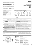
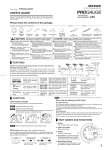
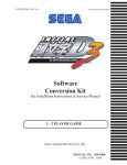
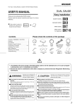
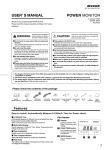
REV COUNTER
RCX
(RCX As of November, 2014 No.1)
REV COUNTER
USER’S MANUAL
SHIFT LAMP & REV COUNTER for Pros
Thank you for purchasing this PIVOT product.
Please read this manual carefully and keep it for future
reference.
● If this produc t is given to
another user, make sure to
include this User’s Manual.
+
Product
Contents
Please check the contents of the package
Contents / WARNING / CAUTION ………
Features ……………………………………
Connecting The Wires ……………………
Installing The Product ……………………
Settings………………………………………
Basic Operation ……………………………
Display The Peak Value and Reset ……
Troubleshooting ……………………………
1
1
2
3
3
4
4
4
Shift Lamp
Cut Connectors
×4
WARNING
Improper use or disregard of these warnings may
result in the injury or death of people.
●Do not work in areas where there is excessive exhaust.
Due to vehicle exhaust emission poisoning or fire may result in a damage to
humans.
●Do not crush the cable.
Please be careful that the cable does not get crushed by the seat rail or car door
steel plate, nor cut by any sharp steel plate as this may cause a poor connection or
an electric short leading to fire or other danger.
●Do not operate while driving.
Operating or checking the display during driving may cause an accident; please use
with the utmost consideration for safety.
●Please securely fasten the product to a stable place and be sure to
store bundle away all wires with tape, etc...
It is very dangerous to pull tangled wires by force or allow tangled wires to interfere
with driving.
White
extension
cord
OBD
Power Cable
with fuse 3A
Controller
Double-sided
Tape
Allen
Wrench
Zip Ties
×5
Earth
terminal
User’s guide
ECU wiring
diagram list
Improper use or disregard of these warnings may
cause injury to persons, damage the product and
other things.
CAUTION
●This product is for DC12V cars;
Installation cannot be carried out on cars with other voltage batteries.
●Just after installation do not exert any strong force on the product.
When double-sided tape is used for an installation be warned that when hot the
tape temporarily losses adhesiveness.
●Do Not Use Chemical Cleansers.
If the unit gets dirty please wipe with a soft cloth to remove any dirt. Do not use
chemical cleansers such as thinner, benzene, or alcohol.
●Do not install the product in any place subject to high temperature
or any place where water may be splashed.
●Make sure to replace all screws and parts to their original place.
●Do not install the product in a place where it will cause distraction.
●Do not, in any manner, process, take apart, or make changes to
this product.
Features
■ Shift Lamp
■ Size
Shift lamp lights up when the set rpm is reached.
[Unit:mm]
46
・Ultra bright LED is easy to see even in full daylight.
・High quality aluminum machined body with swivel neck.
■ Digital Tachometer
High precision display for setting shift lamp and viewing rpm.
・High precision display of engine rpm up to 9999 in 1 rpm units.
20
50
32
60
(Shift Lamp)
(Controller)
・For night driving select auto low lighting or synchronize with parking lights.
Part Names of the Controller
(Front)
(Backside)
・Shift lamp settings can be made in units of 100 rpm.
・View real time and peak engine rpm.
REV COUNTER
SET
PEAK
rpm
・Compact design needs no space.
■ Alarm
Alarm sounds at shift point for 0.5 seconds.
■ Easy Installation
Can be easily installed in some model TOYOTA and DAIHATSU cars
directly by connecting to the diagnostics connector. Other models can be
connected to the ECU.
■ Compatible Vehicles
12 V Gasoline Engine Cars (some diesel engine models)
For 1・2・3・4・5・6・8 cylinder models.
1
2
4
5
3
1 Display
RPM and each setting display
2 SET(
Change each setting
) switch
PEAK( ) switch
3 4 Light sensor
6
Peak and change each setting
For Automatically low lighting
5 5-pin Connector
Connect to the 5-pin Connector of Power cable
6 2-pin Connector
Connect to the 2-pin Connector of Shift Lamp
1
Connecting the Wires
1
Type
Connect to the Power and RPM signal
A
Car models with a ● or ◎ mark in the
: “ECU Wiring Diagram List”
Type
= Use cut connector (or solder)
B:For Popular Models (other than TOYOTA, DAIHATSU and MINI)
Connect to the diagnostic
monitor connector
OBD
Connector
(Some of TOYOTA, DAIHATSU and MINI)
Backside of the controller
Connect to the diagnostic
monitor connector
Backside of the controller
ECU
Engine Computer,
etc.
TA
Cut off
OBD
Connector
at the base
Red
Insulate the cut
Black
off part with tape
White
5-pin
connector
5-pin
connector
White ※1
C
white wire is not long
※1 Ife nthe
ough, please use the
white wire provided in this package to extend the length.
Type : If you are not using the diagnostic monitor connector
If you are wiring directly cut off and insulate all wires at the base of the OBD connector.
1
2
Cut off at the base
Backside of the controller
IGN (or Normal power)
Red
Black
White
←To controller
OBD
connector
Wiring place
Red
Black
White
Orange
Orange wire
12V with key switch ON (or Normal power)
Screw to gain earth, etc
Backside of the controller
●Synchronize with parking lights
⇒ Need to make wiring
5-pin
connector
●Automatically low lighting
⇒ No need to make wiring
RPM signal
To get the RPM
signal from other
than the ECU
Orange
Parking
light
Cut the black tube of the wire tip and connect.
12V with parking lights ON
When another device is already
connected to the RPM signal
from the ECU
... and that device works properly keep that wiring.
... and the meter or other device stops working properly or sometimes becomes unstable disconnect from
the ECU wire and get the RPM from the minus terminal of ignition coil or diagnosis. (Follow the directions
as written below)
●To get the RPM signal from diagnosis
(check connector)
Location of the
RPM signal (IG − )
Ex : in case of
●To get the RPM signal from
the ignition coil
White wire ー
MAZDA EUNOS
ROADSTER
(NA6C)
Ignition coil
Connect to the Shift Lamp
This may be caused by the individual wiring system
of that model of car. Change the cylinder setting to
“1”. (See page 3 “SETTINGS A” for details.)
About Using OBD Products in Combination
Insert the 2-pin connector from the shift lamp into the 2-pin connector at the back
of the controller.
Shift Lamp
Backside of the controller
W h e n conn e c t ing t h e R PM signal to t h e
ignition coil or diagnosis and the indicated
rpm on the meter may be obviously lower
than the actual rpm as shown on tachometer
Ex : For a 6 cylinder car, the reading should be 3000
rpm, but display shows 500 rpm.
←To controller
←To controller White wire
2
Insulate the cut off
part with tape
White
Details
IGN
Illumi
White
extension wire
※1
GND
TA
Cut connector
TA
Earth
Black
5-pin
connector
■ Explanation of wires
Color
See【Reference 2】
ECU
Engine Computer,
etc.
Red
If you wish to use REV COUNTER in combination with products in
our 3-drive Series (FLAT or COMPACT) or other OBD products, the
“ O B D 2 W i r i n g K i t O B D - E H ” (s o l d s e p a r a t e l y ¥ 3 , 2 0 0 ) m a k e s
installation a snap.
For more details about using combinations of products see here.
⇒ http://pivotjp.com/obd-e/
using REV COUNTER with products mentioned above, they can
*When
only be used together in compatible model vehicles for both products.
2-pin connector
【Reference 1】Notes about using the OBD Connector
Make sure to grip the
distended por tions when
pulling it out or inserting it.
CAUTION
Do not pull on the wires
when trying to remove the
connector; the wires may
become disconnected.
If you unable to get a grip on the distended portions.
With some car models
it may be dif ficult to
get a good grip on the
connector.
【Reference 2】How to use the Cut Connectors
1
10 mm
Peel off of the vinyl
cover at connection.
2
10 mm
Peel off of the vinyl
cover at the end of
the product’ s wire.
3
Wrap around both
wire coils.
【Reference 3】How to use provided earth terminal
4
Close tightly with
cut connector.
* When crimping, please use crimpers or use pliers to bend and then solder together.
2
I n s u c h c a s e, p u l l
out the connector by
pulling on the end of
the zip tie.
5
Insulate with
vinyl tape.
1. Peel off about 10mm of vinyl covering from the tip of
the black wire.
2. Bend the outside wires around the core to
Crimp down
make the wire thicker.
3. Crimp down on the earth terminal.
4. Connect it to a earth screw.
Fastening the products
Installation of the Controller
Installation of the Shift Lamp
(Installation Example)
(Installation Method)
(Installation Example)
On the dashboard
Adjust to
designed
angle
① Fasten using the
double-sided tape.
(Clean the surface;
removing all oil or dust.)
Double-sided
tape (included)
On the steering
column cover
Controller
Double-sided tape
(included)
Below the
meter hood
Clean to remove
oil or dust
② After deciding the
position and angle of
the meter face, fasten
the hexagonal bolts on
both sides to secure.
Clean to remove
oil or dust
(Installation Method)
On the
meter hood
Hexagonal bolt
On the steering
column cover
Fasten using the double-sided tape.
(Clean the surface; removing all oil or dust.)
Settings
SETTING
A
SETTING
C
Cylinder Number Setting
Set the cylinder number for the car being used.
ON
1
Press the SET
switch for 5 seconds
3
Down
Press the SET switch for 5 seconds
during the key switch ON (engine not running)
2
Cylinder display
Ex)
Up
Press the switch to change
the pattern and set to the
proper one.
Changes are only necessary for those car models listed below.
NISSAN (FAIRLADY Z Z33)・MAZDA (after 2002)・
MITSUBISHI (COLT and others)・SUBARU (early type of PLEO and others)
※See the “ECU Wiring Diagram List” for details.
3
4
2
5
6
8
Display
5
With no operation
for 5 seconds
4
With no
operation for
5 seconds
5
Display off
or
Special A
3
4
Press the PEAK switch
for 5 seconds
Press the PEAK switch for 3 seconds during
the key switch ON (engine not running)
Patterns for cylinder settings display
2
ON
1
(The factory default setting is for a four-cylinder engine)
1- cylinder
Switching the signal level
Display off
SETTING
D
※ For one and two cylinder engines, set the signal level switch to two.
⇒ See SETTING C : Switching the signal level for details.
The display will change with each pressing of the switch.
Press
the PEAK
If the level
If the
is small
generic car
switch
Alarm Setting
Make Alarm setting for the sound during light emission of Shift Lamp.
●The factory default setting is for a four-cylinder engine. After setting is
changed, the last setting will be displayed.
1
Press the SET
switch
for 3 seconds
While displaying RPM,
press the SET switch for 3 seconds.
●If the engine is a two cycle engine, multiply the number of cylinder by two.
(e.g., For a two-cycle three-cylinder engine the setting would be six.)
2
【Reference】
One-cylinder : Some models of NISSAN or MAZDA
Two-cylinder : Some models of MAZDA or SUBARU
Four-cylinder : Rotary engine (RX-7)
Special A : Some models of NISSAN, etc.
RPM display
Ex)
3
With no
operation for
5 seconds
4
5
RPM display
Current setting
display (Ex; Alarm on)
Press
the SET switch
The display will change with each pressing of the switch.
Alarm ON
SETTING
B
●Alarm sounds when you make each settings even if Alarm set to OFF.
RPM Setting
SETTING
E
Make RPM setting for turning on the Shift Lamp.
1
Press the
SET switch
RPM display
While displaying RPM,
press the SET switch once.
2
Alarm OFF
4
5
With no
operation for
5 seconds
RPM display
Make setting of auto low lighting of Shift Lamp.
1
Current setting
display (Ex; 3500rpm)
Ex)
The Shift Lamp does not lit during setting.
3
Down
Up
Press the switch to change
the RPM setting
Pressing
button one time will
decrease the RPM setting by 100 rpm;
pressing
but ton will increase the
setting by 100 rpm.
※Holding down the either button will rapidly change the setting.
Low lighting setting
RPM display
Press the PEAK
switch
for 3 seconds
While displaying RPM,
press the PEAK switch for 3 seconds.
2
3
Ex)
With no
operation for
5 seconds
4
5
RPM display
Current setting display
(Ex; Low lighting ON)
Press
the SET switch
The display will change with each pressing of the switch.
Low lighting ON
Low lighting OFF
●This function doesn’t work if the Shift Lamp synchronizes with parking lights
with connecting to Orange code.
●If the controller is installed dark place and the light sensor of controller could
not sense the change of lights, the Shift Lamp might keep low lighting.
3
Operation
ENGINE START
Key switch ON (engine not running)
Display : Engine Revolution display
Display: Lamp off
SETTING
B
Press the
SET switch
for 3 seconds
Press
the PEAK
switch
Press
the SET
switch
RPM
Setting
PEAK Value
Display
SETTING
D
Alarm
Setting
SETTING
E
Low lighting
Setting
Press the
PEAK switch
for 5 seconds
Press the
SET switch
for 5 seconds
Press the
PEAK switch
for 3 seconds
SETTING
A
Cylinder
Number Setting
With no operation
for 5 seconds
SETTING
C
Switching
the signal level
With no operation
for 5 seconds
*For details about settings see each [SETTINGS] on page 3.
Peak Display and Reset the Peak Value
Display the Peak value
1
Reset the Peak value
1
Press the
PEAK switch
RPM display
While displaying RPM,
press the PEAK switch once.
2
Ex)
Press the PEAK switch
for 3 seconds
While displaying Peak value, press the PEAK switch for 3 seconds to reset
the Peak value and go back to RPM display.
Peak value display
(Ex; Peak value= 6850rpm)
While displaying Peak value, maximum of dot will light.
3
With no operation
for 5 seconds
4
RPM display
Troubleshooting
Trouble
With the engine running the controller does
not show the rpm.
Possible Causes
Poor connection of each wire.
Possible Solutions
Please reconfirm whether wiring and connections are correct
or not.
Poor connection of OBD connector.
The signal detection level is not correct.
See page 3 [SETTING C] and [ECU Wiring Diagram List],
make any necessary changes.
The cylinder setting is wrong.
Due to difference in accuracy, readings may not be the same
as those on the standard tachometer.
See page 3 [SETTING A] and make any necessary changes.
The signal detection level is not correct.
See page 3 [SETTING C] , make any necessary changes.
The engine rpm has not reached the set shift
point.
See page 3 [SETTING B] , make any necessary changes.
Poor connection of 2-pin connector.
Please reconfirm whether wiring and connections are correct
or not.
Poor connection of orange wire.
Please reconfirm whether wiring and connections are correct
or not.
Poor wiring of orange wire.
Please reconfirm whether wiring and connections are correct
or not.
The Shift Lamp keeps low lighting.
The controller is installed a dark place.
Please move the controller to where it can sense the change
of lights.
The display of the controller is operating even
when the engine has been stopped.
Noise from the car (door locks and so on) may
cause it to temporarily operate.
If the operation is only temporary it is not a malfunction; but if
it still causes worry cut the red wire in the OBD connector
and connect it to IGN.
The auto-power window function and/or other
electronic devices are re-set.
This is due to the minus terminal on the
battery being disconnected.
R e - c o n n e c t t h e m i n u s te r m i n a l a n d fo l l ow r e - s e t t i n g
instructions for any affected devices.
The displayed values are very different from
the standard meter and others.
The Shift Lamp does not light up.
Even with the parking lights on, brightness of
the shift lamp does not decrease.
※Our products have already been recognized as our Industrial Property or are in the process of receiving Industrial Property status.
※We plan in the near future to take all possible legal measures to protect against unfair competition from look-alike products using similar designs, regulating
characteristics, circuitry and circuitry layout.
※We strictly prohibit the unlicensed use of the PIVOT trademark and the unauthorized use of PIVOT User’s Manual.
4
PIVOT CORPORATION 87-3, Shimookada Okada, Matsumoto-shi, Nagano, 390-0313 JAPAN
http://pivotjp.com/