1
AS-i 3.0 PROFIBUS Gateway in Stainless Steel
User manual
AS-i 3.0 specification
Revision date: 2012-03-28
Subject to modifications without notice.
Generally, this manual refers to products
without mentioning existing patents,
utility models, or trademarks.
The absence of any such references does
not indicate that a product is patent-free.
© Bihl+Wiedemann GmbH
Flosswoerthstr. 41
D-68199 Mannheim
AS-i 3.0 PROFIBUS Gateway in Stainless Steel
Table of contents
Table of contents
AS-i 3.0 PROFIBUS Gateway in Stainless Steel
1
1.1
2
2.1
2.1.1
Abbreviations ................................................................................................... 8
General .................................................................................................. 9
Product information......................................................................................... 9
AS-i 3.0 PROFIBUS Gateway in Stainless Steel ........................................................... 9
2.2
New Generation of AS-i Gateways with ethernet diagnostics interface ... 10
2.3
AS-i specification 3.0..................................................................................... 10
2.4
Conformity statement .................................................................................... 11
2.5
Certification according to DIN EN ISO 9001 : 2000 ..................................... 11
2.6
Hazardous Location Information .................................................................. 11
2.6.1
3
Products marked “CL I, DIV 2, GP A, B, C, D”............................................................ 11
Safety................................................................................................... 13
3.1
Intended use................................................................................................... 13
3.2
General safety information ........................................................................... 13
3.2.1
4
4.1
4.1.1
5
Issue date: 28.3.2012
Symbol catalog ..................................................................................... 8
Disposal ......................................................................................................................... 13
Spezifications ..................................................................................... 14
Technical data ................................................................................................ 14
Data sheet ...................................................................................................................... 14
Installation - PROFIBUS single/double master ................................ 17
5.1
Dimensions..................................................................................................... 17
5.2
Connections ................................................................................................... 17
5.3
Installing in the control cabinet .................................................................... 17
5.4
Removing........................................................................................................ 18
5.5
Electrical Connection .................................................................................... 18
5.6
Startup ............................................................................................................ 19
5.6.1
5.6.2
Switching to advanced display mode ......................................................................... 19
Setting the PROFIBUS-DP address 14 ........................................................................ 19
5.7
Connecting AS-i Slaves................................................................................. 20
5.8
Error tracing ................................................................................................... 21
5.8.1
Faulty slaves.................................................................................................................. 21
Subject to technical modifications; no responsibility is accepted for the accuracy of this information
Internet: www.bihl-wiedemann.de • Flosswoerthstr. 41
• D-68199 Mannheim
© Bihl+Wiedemann GmbH
phone: +49 621 33 996-0 • fax: +49 621 3 39 22 399
3
AS-i 3.0 PROFIBUS Gateway in Stainless Steel
Table of contents
5.8.2
Error display (last error) ............................................................................................... 21
5.9
Quick setup..................................................................................................... 22
5.10
Addressing...................................................................................................... 23
5.10.1
Program slave 0 to address 6....................................................................................... 23
6
Installation - PROFIBUS Basic Master ............................................. 24
6.1
Dimensions ..................................................................................................... 24
6.2
Electrical Connection..................................................................................... 24
6.3
Startup............................................................................................................. 25
6.3.1
6.3.2
6.3.3
6.3.4
6.3.5
6.3.5.1
6.3.5.2
6.3.5.3
6.3.5.4
7.1
7.1.1
7.1.2
7.1.3
7.1.4
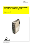
Electrical connection ......................................................................... 30
Overview of terminals, indicators and operating elements ....................... 30
BWU1567, BWU1775, BWU1599, BW1653, BWU1773, BWU1891,
BWU1568, BWU1776, BWU1600, BW1654, BWU1774, BWU1569,
BWU1777, BWU1601, BW1655 ................................................................................. 30
BWU1702, BWU1703, BWU2234 ................................................................................... 31
BWU2544, BWU2545, BWU2546 ................................................................................... 32
BWU1746 ........................................................................................................................ 33
7.2
AS-i bus connection....................................................................................... 34
7.3
Information about the device types.............................................................. 34
7.4
AS-i and power supply terminal assignments............................................. 34
7.4.1
7.4.2
7.4.3
7.4.4
7.4.5
7.4.6
7.5
7.5.1
7.6
7.6.1
7.6.2
7.7
4
Electrical connection BWU1567, BWU1775, BWU1599, BW1653,
BWU1773, BWU2544 ................................................................................................. 35
Electrical connection: BWU1702.................................................................................. 36
Electrical connection BWU1891 ................................................................................... 37
Electrical connection BWU1568, BWU1776, BWU1600, BW1654,
BWU1703, BWU1774, BWU2545 .............................................................................. 38
Electrical connection BWU1569, BWU1777, BWU1601, BW1655,
BWU2234, BWU2546 ................................................................................................. 39
Electrical connection BWU1746 ................................................................................... 40
PROFIBUS interface....................................................................................... 41
Terminating resistors on the PROFIBUS network..................................................... 41
Diagnostics interface ..................................................................................... 42
BWU1567, BWU1775, BWU1599, BW1653, BWU1773, BWU1891,
BWU1568, BWU1776, BWU1600, BW1654, BWU1774, BWU1569,
BWU1777, BWU1601, BW1655 ................................................................................. 42
BWU2544, BWU2545, BWU2546 ................................................................................... 42
Chip card......................................................................................................... 42
Subject to technical modifications; no responsibility is accepted for the accuracy of this information
Internet: www.bihl-wiedemann.de
• Flosswoerthstr. 41
• D-68199 Mannheim
© Bihl+Wiedemann GmbH
phone: +49 621 33 996-0 • fax: +49 621 3 39 22 399
Issue date: 28.3.2012
7
Setting the PROFIBUS-DP address ............................................................................. 25
Switching to configuration mode................................................................................. 25
Error display (last error) ............................................................................................... 26
Connecting AS-i Slaves ................................................................................................ 26
Store AS-i configuration ............................................................................................... 27
AddressingDelete slave address 5 ............................................................................... 27
Programming slave 0 to address 4 ............................................................................... 28
Error tracingIncorrect slaves (one error)....................................................................... 29
Faulty slaves (multiple errors)....................................................................................... 29
AS-i 3.0 PROFIBUS Gateway in Stainless Steel
Table of contents
7.7.1
7.7.1.1
7.7.1.2
7.7.1.3
7.7.1.4
7.7.1.5
7.7.1.6
7.8
7.8.1
7.8.2
Indicators and operating elements .............................................................. 45
LED indicators – master ............................................................................................... 45
Buttons........................................................................................................................... 46
8
Operation in advanced display mode ............................................... 47
9
PROFIBUS DP ..................................................................................... 48
9.1
9.1.1
9.1.1.1
9.1.1.2
9.1.1.3
9.1.2
9.1.2.1
9.1.3
9.1.3.1
9.1.3.2
9.1.3.3
9.1.3.4
DP Telegrams ................................................................................................. 48
Diagnostics.................................................................................................................... 48
Diagnostic description for BWU1567, BWU1568, BWU1569,
BWU1599, BWU1600, BWU1601, BW1653, BW1654, BW1655,
BWU1702, BWU1703, BWU1746, BWU1773, BWU1774, BWU1775,
BWU1776, BWU1777, BWU1891, BWU223449
Diagnostic description for BWU2544, BWU2545, BWU2546...................................... 52
Parameters................................................................................................................... 53
Configuration DP/V0 (cyclic data) ............................................................................... 56
Options......................................................................................................................... 56
I/O Data........................................................................................................................... 58
Process data ................................................................................................................ 58
AS-i 16-bit data ............................................................................................................ 60
Command interface...................................................................................................... 61
Safety Control/Status ................................................................................................... 62
9.2
DP/V1............................................................................................................... 63
9.3
Restrictions .................................................................................................... 63
10
Advanced Diagnostics for AS-i Masters .......................................... 65
10.1
List of corrupted AS-i Slaves (LCS) ............................................................. 65
10.2
Protocol analysis: Counters for corrupted data telegrams ....................... 65
10.3
Offline Phase for Configuration Errors ........................................................ 66
10.4
Functions of the AS-i Fault Detector............................................................ 66
10.4.1
10.4.2
10.4.3
10.4.4
10.5
Issue date: 28.3.2012
Using the chip card....................................................................................................... 42
Card unformatted ......................................................................................................... 43
Data not compatible ..................................................................................................... 43
Card empty................................................................................................................... 43
Data compatible ........................................................................................................... 43
Data in the device and on the chip card identical......................................................... 44
Data in the device and on the chip card not identical................................................... 44
10.5.1
10.5.2
10.5.3
10.5.4
10.5.5
10.5.6
10.5.7
10.5.8
Duplicate address detection ........................................................................................ 66
Earth/Ground Fault Detector........................................................................................ 66
Noise Detector............................................................................................................... 67
Over-voltage Detector................................................................................................... 67
Functions of the new generation of AS-i Gateways ................................... 68
C-programmable Gateways.......................................................................................... 68
Interchangeable memory card ..................................................................................... 68
Earth fault monitor ........................................................................................................ 68
Current can be read directly on the unit ..................................................................... 69
Self-resetting fuses....................................................................................................... 70
AS-i Power24V capable ................................................................................................ 70
Ethernet diagnostics interface with web server......................................................... 70
Transitionless operating mode changes .................................................................... 70
Subject to technical modifications; no responsibility is accepted for the accuracy of this information
Internet: www.bihl-wiedemann.de • Flosswoerthstr. 41
• D-68199 Mannheim
© Bihl+Wiedemann GmbH
phone: +49 621 33 996-0 • fax: +49 621 3 39 22 399
5
AS-i 3.0 PROFIBUS Gateway in Stainless Steel
Table of contents
11
System startup using AS-i Control Tools ........................................ 72
11.1
Windows software AS-i Control Tools ......................................................... 72
11.2
PROFIBUS DP Master Simulator................................................................... 75
11.3
Serial PROFIBUS Master ............................................................................... 76
11.4
Additional information ................................................................................... 76
12
Appendix: Example for startup on a Siemens S7 ........................... 77
12.1
Hardware configuration ................................................................................. 77
12.1.1
12.1.2
Electrical connection for AS-i ...................................................................................... 77
Electrical connection for PROFIBUS DP ..................................................................... 78
12.2
SIMATIC Step 7 Configuration ...................................................................... 78
12.2.1
12.2.2
12.2.3
12.2.4
12.2.4.1
12.2.4.2
12.2.4.3
12.2.5
12.2.6
12.2.6.1
12.2.6.2
12.2.7
13
13.1
Configuration of the Hardware ..................................................................................... 78
Insert AS-i 3.0 PROFIBUS Gateway in Stainless Steel............................................... 81
Configuring AS-i 3.0 PROFIBUS Gateway in Stainless Steel
in-/output.................................................................................................................... 84
AS-i 3.0 PROFIBUS Gateway in Stainless Steel parameters ..................................... 87
General DP parameters................................................................................................ 89
Device-specific parameters .......................................................................................... 89
Hex parameterizing....................................................................................................... 93
SIMATIC Step7 blocks................................................................................................... 93
Variable table VAT_ASI_IO ........................................................................................... 94
AS-i flags byte 0, input bits 7 - 4 ................................................................................... 96
AS-i flags byte 0, output bits 7 - 4................................................................................. 96
System behavior on AS-i Config Error ........................................................................ 98
Codes Indicated by the Display ...................................................... 103
Codes indicated by AS-i Gateway with standard function range ............ 104
14
Accessories ...................................................................................... 105
15
Glossary ............................................................................................ 107
16
Reference List .................................................................................. 112
16.1
Your opinion is important to us!..................................................... 113
Issue date: 28.3.2012
17
Manual: “AS-i 3.0 Command Interface“ ..................................................... 112
6
Subject to technical modifications; no responsibility is accepted for the accuracy of this information
Internet: www.bihl-wiedemann.de
• Flosswoerthstr. 41
• D-68199 Mannheim
© Bihl+Wiedemann GmbH
phone: +49 621 33 996-0 • fax: +49 621 3 39 22 399
AS-i 3.0 PROFIBUS Gateway in Stainless Steel
Conformity Statement
Conformity Statement
The AS-i 3.0 PROFIBUS Gateway in Stainless Steel has been developed
and produced in accordance with the applicable european standards and
directives. The conformity statement according to the EC EMC-, low voltage, and -machinery directive can be sent to by request.
Additional information can be found in the Bihl+Wiedemann GmbH basic
catalogue or in the online catalogue in internet.
Issue date: 28.3.2012
Subject to technical modifications.
Subject to technical modifications; no responsibility is accepted for the accuracy of this information
Internet: www.bihl-wiedemann.de • Flosswoerthstr. 41
• D-68199 Mannheim
© Bihl+Wiedemann GmbH
phone: +49 621 33 996-0 • fax: +49 621 3 39 22 399
7
AS-i 3.0 PROFIBUS Gateway in Stainless Steel
Symbol catalog
1.
Symbol catalog
Information!
This symbol indicates important information.
Attention!
This symbol warns of a potential failure. Non-compliance may lead to interruptions of
the device, the connected peripheral systems, or plant, potentially leading to total malfunctioning.
Warning!
This symbol warns of an imminent danger. Non-compliance may lead to personal injuries that could be fatal or result in material damages and destruction.
1.1
Abbreviations
Information!
Issue date: 28.3.2012
Additional information can be found in section <Glossary>.
8
Subject to technical modifications; no responsibility is accepted for the accuracy of this information
Internet: www.bihl-wiedemann.de
• Flosswoerthstr. 41
• D-68199 Mannheim
© Bihl+Wiedemann GmbH
phone: +49 621 33 996-0 • fax: +49 621 3 39 22 399
AS-i 3.0 PROFIBUS Gateway in Stainless Steel
General
2.
General
2.1
Product information
This system manual applies to the following Bihl+Wiedemann GmbH equipment:
Control II
Control III (option)1
Class 1 Div 2 certification
Power supply decoupling unit
LCD display (alpha numeric)
LED display (3-digit)
−
−
−
•
−
•
−
−
−
−
•
−
•
−
•
−
−
•
−
•
•
−
−
•
−
−
−
•
−
•
−
−
−
−
−
•
−
•
−
−
−
•
•
−
•
−
−
−
−
•
−
•
−
−
−
−
•
−
•
−
•
−
−
•
−
•
•
−
−
−
•
−
•
−
•
•
−
•
−
−
−
−
−
−
−
•
−
•
−
•
−
−
−
•
•
−
2
−
−
•
−
−
−
•
•
−
2
−
•
•
−
•
−
•
•
−
PROFIBUS
2
−
−
•
•
−
−
•
•
−
PROFIBUS
2
•
−
•
•
−
•
•
•
−
1
−
−
−
−
−
−
−
−
•
1
•
−
1
−
−
1
−
•
PROFIBUS
1
•
−
•
PROFIBUS
1
•
−
•
BWU1773
PROFIBUS
1
−
−
−
BWU1891
PROFIBUS
1
•
−
BWU1568
PROFIBUS
2
•
−
BWU1703
PROFIBUS
2
−
−
BWU2545
PROFIBUS
2
−
•
BWU1600
PROFIBUS
2
•
−
BW1654
PROFIBUS
2
•
−
BWU1774
PROFIBUS
2
−
BWU1569
PROFIBUS
2
BWU2234
PROFIBUS
BWU2546
PROFIBUS
BWU1601
BW1655
BWU1746
PROFIBUS
field bus interface
Ethernet diagnostic interface
−
RS 232 diagnostic interface
•
number of AS-i Masters
Recognition of duplicate addresses
AS-i 3.0 PROFIBUS Gateway in Stainless Steel
Article no.
2.1.1
BWU1567
PROFIBUS
BWU1702
PROFIBUS
BWU2544
PROFIBUS
BWU1599
BW1653
BWU1775
BWU1776
Tab. 2-1. Function range of "AS-i 3.0 PROFIBUS Gateway in Stainless Steel"
1.
9
Activation art. no BW2582
Subject to technical modifications; no responsibility is accepted for the accuracy of this information
Internet: www.bihl-wiedemann.de
• Flosswoerthstr. 41
• D-68199 Mannheim
© Bihl+Wiedemann GmbH
phone: +49 621 33 996-0 • fax: +49 621 3 39 22 399
Issue date: 28.3.2012
BWU1777
AS-i 3.0 PROFIBUS Gateway in Stainless Steel
General
The AS-i/PROFIBUS Gateways serve to connect AS-i systems to the superordinate PROFIBUS. The gateways act as a master for AS-i and as a slave on
PROFIBUS.
The AS-i/PROFIBUS Gateways are designed to connect AS-i systems to an upper-level PROFIBUS network. The gateways act as a master for AS-i and as a
slave on PROFIBUS.
All AS-i functions can be used cyclically as well as acyclically via PROFIBUS
DP/ V1.
For the cyclical data transfer up to 32 bytes of I/O data can be transferred as binary data for one AS-i network. Additionally, analog signals and all available commands of the new AS-i specification can be transferred via the command channel
through PROFIBUS.
On the serial PROFIBUS Master AS-i Control Tools can be used to monitor the
AS-i data online via PROFIBUS DP/V1.
2.2
New Generation of AS-i Gateways with ethernet diagnostics interface
The plus points of the new Gateway generation at a glance:
•
Gateways now programmable in C
•
Ethernet diagnostics interface for remote diagnostics
•
Integrated web server: diagnostics for the Gateways and the AS-i circuits
over Ethernet possible with no additional software
•
GSD file for PROFIBUS and GSDML file for PROFINET already stored in the
web server
•
Earth fault monitor distinguishes between AS-i cable and sensor cable
•
Current from both AS-i circuits in the "1 Gateway, 1 power supply for 2 AS-i
circuits" version can now be read directly on the unit
•
Self-resetting fuses in the "1 Gateway, 1 power supply for 2 AS-i circuits" version
•
Device temperature display
•
AS-i Power24V capable
•
Interfaces for virtually every bus system and Ethernet solution
Information!
See also section <Functions of the new generation of AS-i Gateways> for further information.
2.3
AS-i specification 3.0
Issue date: 28.3.2012
The AS-i 3.0 devices already fulfil the AS-i specification 3.0.
The previous specifications (2.1 and 2.0) are supported as well.
Advanced Diagnostics
Subject to technical modifications; no responsibility is accepted for the accuracy of this information
Internet: www.bihl-wiedemann.de • Flosswoerthstr. 41
• D-68199 Mannheim
© Bihl+Wiedemann GmbH
phone: +49 621 33 996-0 • fax: +49 621 3 39 22 399
10
AS-i 3.0 PROFIBUS Gateway in Stainless Steel
General
Diagnostics, which go far beyond the standard diagnostics facilitate the simple
detection of the occasionally occurring configuration errors and further irritations
towards the AS-i communication. So in case of an error the down time of machines can be minimized or you can initiate preventive maintenance.
Commissioning and monitoring
Commissioning, debugging and setting up of the AS-i parameters can also be accomplished with the use of push-buttons on the frontside of the gateway, the display and the LEDs. It is also possible to do the configuration with the software
"AS-i Control Tools".
2.4
Conformity statement
The AS-i 3.0 PROFIBUS Gateway in Stainless Steel has been developed and
manufactured in accordance with the applicable european standards and directives.
Information!
The corresponding conformity statement can be found at the very beginning of
this system manual.
2.5
Certification according to DIN EN ISO 9001 : 2000
The manufacturer of the product possesses a certified quality assurance system
in accordance with ISO 9001.
Information!
The current certificate can be viewed in internet:
http://www.bihl-wiedemann.de
2.6
2.6.1
Hazardous Location Information
Products marked “CL I, DIV 2, GP A, B, C, D”
The following information applies when operating this equipment in hazardous locations:
Products marked “CL I, DIV 2, GP A, B, C, D” are suitable for use in Class I Division 2 Groups A, B, C, D, hazardous locations and nonhazardous locations only.
Each product is supplied with markings on the rating nameplate indicating the
hazardous location temperature code.
Issue date: 28.3.2012
Combinations of equipment in your system are subject to investigation by the local authority having jurisdiction at the time of installation.
11
Subject to technical modifications; no responsibility is accepted for the accuracy of this information
Internet: www.bihl-wiedemann.de
• Flosswoerthstr. 41
• D-68199 Mannheim
© Bihl+Wiedemann GmbH
phone: +49 621 33 996-0 • fax: +49 621 3 39 22 399
AS-i 3.0 PROFIBUS Gateway in Stainless Steel
General
Explosion hazard!
•
Do not disconnect equipment unless power has been removed or the area is
known to be nonhazardous.
•
Do not disconnect connections to this equipment unless power has been
removed or the area is known to be nonhazardous. Secure any external connections that mate to this equipment by using screws, sliding latches,
threaded connectors, or other means provided with this product.
•
Only use the RS 232 connector if the area is nonhazardous.
•
Substitution of components may impair suitability for Class I, Division 2.
Issue date: 28.3.2012
If this product contains batteries, they must only be changed in an area known to be
nonhazardous.
Subject to technical modifications; no responsibility is accepted for the accuracy of this information
Internet: www.bihl-wiedemann.de • Flosswoerthstr. 41
• D-68199 Mannheim
© Bihl+Wiedemann GmbH
phone: +49 621 33 996-0 • fax: +49 621 3 39 22 399
12
AS-i 3.0 PROFIBUS Gateway in Stainless Steel
Safety
3.
Safety
3.1
Intended use
Warning!
This symbol warns of a possible danger. The protection of operating personnel and the
system against possible danger is not guaranteed if the control interface unit is not
operated in accordance to its intended use.
3.2
General safety information
Warning!
Safety and correct functioning of the device cannot be guaranteed if any operation
other than described in this operation manual is performed. Connecting the equipment
and conducting any maintenance work under power must exclusively be performed by
appropriately qualified personnel. In case a failure cannot be eliminated, the device
must be taken out of operation and inadvertently operation must be prevented. Repair
work must be performed by the manufacturer only. Additions or modifications to the
equipment are not permitted and will void the warranty.
Information!
The operator is responsible for the observation of local safety standards.
3.2.1
Disposal
Information!
Electronic waste is hazardous waste. Please comply with all local ordinances when
disposing this product!
Issue date: 28.3.2012
The device does not contain batteries that need to be removed before disposing it.
13
Subject to technical modifications; no responsibility is accepted for the accuracy of this information
Internet: www.bihl-wiedemann.de
• Flosswoerthstr. 41
• D-68199 Mannheim
© Bihl+Wiedemann GmbH
phone: +49 621 33 996-0 • fax: +49 621 3 39 22 399
AS-i 3.0 PROFIBUS Gateway in Stainless Steel
Spezifications
4.
Spezifications
4.1
Technical data
Information!
The technical data are placed in the data sheet. Please view the current version on the
web page: http://www.bihl-wiedemann.de/englisch/index.html.
4.1.1
Data sheet
Article no.
BWU1567
BWU1568
BWU1569
BW1653
BW1654
BW1655
BWU1746
BWU1773
BWU1774
BWU1891
BWU2544
BWU2545
BWU2546
Class 1 Div. 2
(Group A, B, C
& D, T-Code 4)
Interface
PROFIBUS interface
IE 61 158 / IEC 61 784-1
Baud rates
9,6 KBaud up to 12 000 KBaud, automatic recognition
DP functions
imaging of the AS-i slaves as I/O Data of the PROFIBUS
complete diagnosis and configuration via the DP Master
Card slot
–
Chip card for
storage of
configuration data
AS-i
150s * (number of slaves + 2)
Cycle time
Operating voltage
AS-i voltage 30V DC
Anzeige
–
AS-i slave
adresses, error
codes
–
menu, AS-i indication of slave
addresses, error messages in plain
text
–
menu, AS-i indication of slave
addresses, error messages in plain
text
7-Segment display
LCD
LED power
power ON
LED PROFIBUS
PROFIBUS Master recognized
LED config error
configuration error
LED U AS-i
AS-i voltage o.k.
LED AS-i active
AS-i normal operation active
LED prg enable
automatic address programming enabled
LED prj mode
master is in configuration mode
Environment
Applied standards
EN 61 000-6-2
EN 61 000-6-4
Housing
Stainless Steel
Operating temperature
0°C … +55°C
Storage temperature
-25°C … +85°C
Protection category DIN EN
60 529
IP20
Maximum tolerable shock and
vibration stress
according EN 61 131-2
500V
Voltage of insulation
Dimensions (W / H / D in mm)
75 / 120 / 83
42 / 120 / 40
460 g
300 g
75 / 120 / 83
75 / 120 / 93
460 g
Issue date: 28.3.2012
Weight
14
Subject to technical modifications; no responsibility is accepted for the accuracy of this information
Internet: www.bihl-wiedemann.de
• Flosswoerthstr. 41
• D-68199 Mannheim
© Bihl+Wiedemann GmbH
phone: +49 621 33 996-0 • fax: +49 621 3 39 22 399
AS-i 3.0 PROFIBUS Gateway in Stainless Steel
Spezifications
Article no.
Number AS-i
Master
Duplicate
addresses
inspector
AS-i
Detector
Programming
and diagnosis
interface
Safety Monitor
integrated
Preprocessing
AS-i Spec.
3.0
BWU1567
1 Master
yes
yes
RS232
optional
no
BWU1568
2 Master
yes
yes
RS232
optional
no
3.0
BWU1569
2 Master out of 1
power supply
yes
yes
RS232
optional
no
3.0
BW1653
1 Master
yes
yes
RS232
no
no
3.0
BW1654
2 Master
yes
yes
RS232
no
no
3.0
BW1655
2 Master out of 1
power supply
yes
yes
RS232
no
no
3.0
BWU1746
1 Master
no
yes
no
no
no
3.0
BWU1773
1 Master
no
yes
no
no
no
3.0
BWU1774
2 Master
no
yes
no
no
no
3.0
BWU1891
1 Master
yes
yes
RS232
no
no
3.0
BWU2544
1 Master
yes
yes
Ethernet
optional
Control III
3.0
BWU2545
2 Master
yes
yes
Ethernet
optional
Control III
3.0
BWU2546
2 Master
yes
yes
Ethernet
optional
Control III
3.0
Bemessungsbetriebsstrom
Article no.
Master power supply,
Master power supply,
max. 200mA out of AS-i circuit 1 ca. 200mA out of AS-i circuit 1
(ca. 70mA ... 200mA),
ca. 70mA out of AS-i circuit 2
max. 200mA out of AS-i circuit 2
(ca. 70mA ... 200mA);
in sum max. 270mA
Version „1 gateway,
1 power supply
for 2 AS-i networks“,
approx. 250mA
(PELV voltage)
Master power supply,
ca. 200mA out of
AS-i circuit
BWU1567
–
–
–
BWU1568
–
–
–
BWU1569
–
–
–
BW1653
–
–
–
BW1654
–
–
–
BW1655
–
–
BWU1746
–
–
–
BWU1773
–
–
–
BWU1774
–
–
BWU1891
–
–
–
–
–
–
–
–
BWU2545
–
–
–
BWU2546
–
–
–
Issue date: 28.3.2012
BWU2544
Subject to technical modifications; no responsibility is accepted for the accuracy of this information
Internet: www.bihl-wiedemann.de • Flosswoerthstr. 41
• D-68199 Mannheim
© Bihl+Wiedemann GmbH
phone: +49 621 33 996-0 • fax: +49 621 3 39 22 399
15
AS-i 3.0 PROFIBUS Gateway in Stainless Steel
Spezifications
BWU1567 BWU1568 BWU1569 BW1653 BW1655 BWU1746 BWU2545 BWU2546
BW1654
BWU1773
BWU1774
BWU1891
BWU2544
Article no.
Redundant power supply out of AS-i:
all fundamental functions of the device remain
available even in case of power failure in one of
the two AS-i networks
–
Current measurement of the AS-i circuits
–
–
–
–
–
Self-resetting adjustable fuses
–
–
–
–
–
AS-i earth fault monitor distinguishes between
AS-i cable and sensor cable
–
–
–
–
–
In version 1 gateway, 1 power supply for 2 AS-i
circuits:
only 1 Gateway + 1 AS-i power supply
for 2 AS-i networks
–
–
–
1
–
–
–
–
–
–
–
–
–
–
–
–
–
(Recognition of duplicate AS-i adresses) except
BWU1746, BWU1773, BWU1774
2
(Optional programmable in C) and
3
(GSD file integrated)
BWU2544, BWU2545, BWU2546
4
AS-i Power24V
The gateways BWU2544, BWU2545 and BWU2546 are AS-i Power24V capable. That means, that all devices can be operated directly
on a 24V (PELV) power supply.
The gateway BWU2546 is optimized with integrated data coupling coils and adjustable self-resetting fuses for safe use also of powerful
24V power supplies.
The gateways BWU2544 and BWU2545 will add in Power24V-operation a BW1943 power supply decoupling unit.
AS-i 3.0 from ID no. 12003 (see lateral label)
BWU1567, BWU1568, BWU1569, BWU1653, BWU1654, BWU1655, BWU1773, BWU1774
Issue date: 28.3.2012
Currently supplied devices correspond as standard AS-i 3.0.
16
Subject to technical modifications; no responsibility is accepted for the accuracy of this information
Internet: www.bihl-wiedemann.de
• Flosswoerthstr. 41
• D-68199 Mannheim
© Bihl+Wiedemann GmbH
phone: +49 621 33 996-0 • fax: +49 621 3 39 22 399
AS-i 3.0 PROFIBUS Gateway in Stainless Steel
Installation - PROFIBUS single/double master
5.
Installation - PROFIBUS single/double master
5.1
Dimensions
55
76
7
75
5.2
120
Connections
5 ... 6 mm / PZ2
0,8 Nm
7 LB.IN
10
2
2 x (0,5 ... 1,5) mm
10
2
2 x (0,5 ... 1,5) mm
AWG
5.3
2 x 24 ...12
Installing in the control cabinet
The AS-i/Gateway is installed in the control cabinet on 35mm DIN rails per DIN
EN 50 022.
Information!
Issue date: 28.3.2012
The enclosure of the AS-i/Gateway is made of stainless steel. The unit is also suitable
for exposed wall mounting.
17
Subject to technical modifications; no responsibility is accepted for the accuracy of this information
Internet: www.bihl-wiedemann.de
• Flosswoerthstr. 41
• D-68199 Mannheim
© Bihl+Wiedemann GmbH
phone: +49 621 33 996-0 • fax: +49 621 3 39 22 399
AS-i 3.0 PROFIBUS Gateway in Stainless Steel
Installation - PROFIBUS single/double master
To install, place the unit on the upper edge of the DIN rail and then snap in the
lower edge.
[1]
[2]
+
5.4
-
+
-
+
-
-
+
-
Removing
+
-
+
1
3
2
To remove, press the holding clamps [2] down using a screwdriver [1], press the
unit firmly against the upper rail guide and lift out.
5.5
Electrical Connection
Information!
Issue date: 28.3.2012
Electrical connections are described in section <Electrical connection>.
Information!
See also section <Operation in advanced display mode> for further information.
Subject to technical modifications; no responsibility is accepted for the accuracy of this information
Internet: www.bihl-wiedemann.de • Flosswoerthstr. 41
• D-68199 Mannheim
© Bihl+Wiedemann GmbH
phone: +49 621 33 996-0 • fax: +49 621 3 39 22 399
18
AS-i 3.0 PROFIBUS Gateway in Stainless Steel
Installation - PROFIBUS single/double master
5.6
Startup
5.6.1
Switching to advanced display mode
classical display
advanced display mode
OK
LCD
.12A
UNKNOWN SLAVE
PROFIBUS
QUICK SETUP
SETUP
SLAVE ADR TOOL
ESC
5.6.2
LCD
menu structure see additional page
Setting the PROFIBUS-DP address 14
OK
OK
LCD
LCD
PROFIBUS ADDRESS
OLD ADDRESS
3
NEW ADDRESS 000
PROFIBUS
QUICK SETUP
ASI SAFETY
2x ↓
OK
LCD
LCD
PROFIBUS ADDRESS
OLD ADDRESS
3
NEW ADDRESS 000
Issue date: 28.3.2012
PROFIBUS ADDRESS
PROFIBUS STATUS
19
Subject to technical modifications; no responsibility is accepted for the accuracy of this information
Internet: www.bihl-wiedemann.de
• Flosswoerthstr. 41
• D-68199 Mannheim
© Bihl+Wiedemann GmbH
phone: +49 621 33 996-0 • fax: +49 621 3 39 22 399
AS-i 3.0 PROFIBUS Gateway in Stainless Steel
Installation - PROFIBUS single/double master
↑
2x OK
OK
LCD
PROFIBUS ADDRESS
OLD ADDRESS
14
NEW ADDRESS 000
PROFIBUS ADDRESS
OLD ADDRESS
3
NEW ADDRESS 010
LCD
2x ESC
4x ↑
LCD
OK
PROFIBUS
QUICK SETUP
SETUP
2x ESC
The device is set to address 3 at the factory.
Connecting AS-i Slaves
Power
Profibus
Profibus
Config error
U AS-i
AS-i active
prg enable
AS-i Master
Power
Config error
U AS-i
AS-i active
prg enable
prj mode
prj mode
AS-i
LCD
. 41
.1
0.5s
AS-i
AS-i
Slave 1
.5
AS-i
Slave 1
0.5s
AS-i
Slave 5
. 24
SEARCHING SLAVES
Issue date: 28.3.2012
AS-i
Slave 5
LCD
AS-i Master
5.7
0.5s
Subject to technical modifications; no responsibility is accepted for the accuracy of this information
Internet: www.bihl-wiedemann.de • Flosswoerthstr. 41
• D-68199 Mannheim
© Bihl+Wiedemann GmbH
phone: +49 621 33 996-0 • fax: +49 621 3 39 22 399
20
AS-i 3.0 PROFIBUS Gateway in Stainless Steel
Installation - PROFIBUS single/double master
5.8
Error tracing
5.8.1
Faulty slaves
Power
LCD
AS-i Master
Profibus
Config error
U AS-i
AS-i active
prg enable
.1
MISSING SLAVE
prj mode
AS-i
2s
AS-i
Slave 1
LCD
.24
AS-i
Slave 5
MISSING SLAVE
AS-i
Slave 24
Power
Power
Profibus
Profibus
Config error
U AS-i
AS-i active
prg enable
Config error
U AS-i
AS-i active
prg enable
prj mode
AS-Interface
prj mode
AS-Interface
AS-Interface
Slave 1
AS-Interface
Slave 1
AS-Interface
Slave 5
AS-Interface
Slave 5
AS-i Master
Error display (last error)
AS-i Master
5.8.2
2s
LCD
HOST ERROR
NO CONNECTION
set/↓
24
AS-Interface
Slave 24
Issue date: 28.3.2012
AS-Interface
Slave 24
21
Subject to technical modifications; no responsibility is accepted for the accuracy of this information
Internet: www.bihl-wiedemann.de
• Flosswoerthstr. 41
• D-68199 Mannheim
© Bihl+Wiedemann GmbH
phone: +49 621 33 996-0 • fax: +49 621 3 39 22 399
AS-i 3.0 PROFIBUS Gateway in Stainless Steel
Installation - PROFIBUS single/double master
5.9
Quick setup
OK
config error
LCD
LCD
.5
STORE AS-INTERFACE
CONFIGURATION
OK
STORE +PRJ MODE
↓
OK
2x ESC
LCD
PROFIBUS
QUICK SETUP
SETUP
SLAVE ADR TOOL
LCD
.
OK
CONFIGURATION OK
LCD
LCD
WARNING:
OUTPUTS MAY BE
RESET
OK
HOST ERROR
NO CONNECTION
↓
LCD
Issue date: 28.3.2012
STORE AS-I
CONFIGURATION
STORE +RUN
STORE +PRJ MODE
Subject to technical modifications; no responsibility is accepted for the accuracy of this information
Internet: www.bihl-wiedemann.de • Flosswoerthstr. 41
• D-68199 Mannheim
© Bihl+Wiedemann GmbH
phone: +49 621 33 996-0 • fax: +49 621 3 39 22 399
22
AS-i 3.0 PROFIBUS Gateway in Stainless Steel
Installation - PROFIBUS single/double master
5.10
Addressing
5.10.1
Program slave 0 to address 6
LCD
. 41
1x ↓
3xOK
SEARCHING SLAVE
SLAVE ADR TOOL
OLD ADDRESS 2
NEW ADDRESS 6
PRG
2x ↓
OK
LCD
PROFIBUS
QUICK SETUP
SLAVE ADR TOOL
SLAVE TEST TOOL
1x ↓
SLAVE ADR TOOL
OLD ADDRESS 2
NEW ADDRESS 6
PRG
OK
LCD
LCD
OK
LCD
SLAVE ADR TOOL
CONNECT NEW SLAVE
OLD ADDRESS
NEW ADDRESS
Master
SLAVE ADR TOOL
LCD
OK
Slave
Modul anschließen/Connect
module/Raccordez le module/
Collegare il modulo/Conecte
modulo
LCD
2x ESC
.6
LCD
UNKNOWN SLAVE
Issue date: 28.3.2012
SLAVE ADR TOOL
OLD ADDRESS 2
NEW ADDRESS 3
PRG
23
Subject to technical modifications; no responsibility is accepted for the accuracy of this information
Internet: www.bihl-wiedemann.de
• Flosswoerthstr. 41
• D-68199 Mannheim
© Bihl+Wiedemann GmbH
phone: +49 621 33 996-0 • fax: +49 621 3 39 22 399
AS-i 3.0 PROFIBUS Gateway in Stainless Steel
Installation - PROFIBUS Basic Master
6.
Installation - PROFIBUS Basic Master
6.1
Dimensions
6.2
Electrical Connection
Information!
Issue date: 28.3.2012
Electrical connections are described in section <Electrical connection>.
24
Subject to technical modifications; no responsibility is accepted for the accuracy of this information
Internet: www.bihl-wiedemann.de
• Flosswoerthstr. 41
• D-68199 Mannheim
© Bihl+Wiedemann GmbH
phone: +49 621 33 996-0 • fax: +49 621 3 39 22 399
AS-i 3.0 PROFIBUS Gateway in Stainless Steel
Installation - PROFIBUS Basic Master
6.3
Startup
Attention!
If PROFIBUS active, no configuration settings by push buttons!
6.3.1
Setting the PROFIBUS-DP address
> 5s
+
mode
set
LCD
003
LCD
0
mode
set
mode
set
004
1
set
!
!
!
0: Address change via PROFIBUS is locked (default).
1: Address change via PROFIBUS is allowed.
126
The device is set to address 3 at the factory.
6.3.2
Switching to configuration mode
> 5s
mode
prj mode
Issue date: 28.3.2012
prj mode
Subject to technical modifications; no responsibility is accepted for the accuracy of this information
Internet: www.bihl-wiedemann.de • Flosswoerthstr. 41
• D-68199 Mannheim
© Bihl+Wiedemann GmbH
phone: +49 621 33 996-0 • fax: +49 621 3 39 22 399
25
AS-i 3.0 PROFIBUS Gateway in Stainless Steel
Installation - PROFIBUS Basic Master
Error display (last error)
Profibus
config error
U AS-i
AS-i active
prg enable
power
AS-i Master
power
Profibus
config error
U AS-i
AS-i active
prg enable
prj mode
prj mode
AS-i
AS-i
AS-i
Slave 1
AS-i
Slave 1
AS-i
Slave 5
AS-i
Slave 5
AS-i
Slave 24
AS-i
Slave 24
LCD
set
024
...
Connecting AS-i Slaves
power
Profibus
Profibus
config error
U AS-i
AS-i active
prg enable
prj mode
AS-i Master
power
config error
U AS-i
AS-i active
prg enable
AS-i Master
6.3.4
AS-i Master
6.3.3
prj mode
AS-i
AS-i
001 LCD
SEA LCD
AS-i
Slave 1
0.5s
005
AS-i
Slave 1
AS-i
Slave 5
0.5s
024
AS-i
Slave 5
0.5s
AS-i
Slave 24
Issue date: 28.3.2012
AS-i
Slave 24
26
Subject to technical modifications; no responsibility is accepted for the accuracy of this information
Internet: www.bihl-wiedemann.de
• Flosswoerthstr. 41
• D-68199 Mannheim
© Bihl+Wiedemann GmbH
phone: +49 621 33 996-0 • fax: +49 621 3 39 22 399
AS-i 3.0 PROFIBUS Gateway in Stainless Steel
Installation - PROFIBUS Basic Master
6.3.5
Store AS-i configuration
> 5s
prj mode
prj mode
mode
config error
LCD
fault
Configuration O.K
6.3.5.1
No PROFIBUS
AddressingDelete slave address 5
config error
U AS-i
AS-i active
prg enable
Configuration mode!
power
Profibus
config error
prj mode
U AS-i
AS-i
AS-i active
prg enable
AS-i
Slave 3
prj mode
003 LCD
AS-i Master
Profibus
AS-i Master
power
AS-i
0.5s
AS-i
Slave 5
005
0.5s
AS-i
Slave 12
012
0.5s
> 5s
set
000
AS-i
Slave 3
0.5s
003
AS-i
Slave 0
0.5s
012
AS-i
Slave 12
Issue date: 28.3.2012
0.5s
Subject to technical modifications; no responsibility is accepted for the accuracy of this information
Internet: www.bihl-wiedemann.de • Flosswoerthstr. 41
• D-68199 Mannheim
© Bihl+Wiedemann GmbH
phone: +49 621 33 996-0 • fax: +49 621 3 39 22 399
27
AS-i 3.0 PROFIBUS Gateway in Stainless Steel
Installation - PROFIBUS Basic Master
6.3.5.2
Programming slave 0 to address 4
0.5s
003
012
0.5s
0.5s
set
031
!
!
!
set
004
0.5s
012
set
002
0.5s
003
set
0.5s
000 LCD
Configuration mode!
set
001
set
> 5s
4
set
LCD 004
AS-i
Slave 12
AS-i
Slave 4
AS-i
Slave 3
AS-i
prg enable
prj mode
AS-i active
U AS-i
Profibus
config error
power
AS-i Master
Subject to technical modifications; no responsibility is accepted for the accuracy of this information
Internet: www.bihl-wiedemann.de
• Flosswoerthstr. 41
• D-68199 Mannheim
Issue date: 28.3.2012
only possible with slave 0!
AS-i
Slave 12
AS-i
Slave 0
AS-i
Slave 3
AS-i
prj mode
prg enable
AS-i active
U AS-i
config error
Profibus
power
AS-i Master
28
© Bihl+Wiedemann GmbH
phone: +49 621 33 996-0 • fax: +49 621 3 39 22 399
AS-i 3.0 PROFIBUS Gateway in Stainless Steel
Installation - PROFIBUS Basic Master
Error tracingIncorrect slaves (one error)
power
Profibus
config error
U AS-i
AS-i active
prg enable
AS-i Master
6.3.5.3
prj mode
AS-i
AS-i
Slave 1
AS-i
Slave 5
005 LCD
AS-i
Slave 24
6.3.5.4
Faulty slaves (multiple errors)
Profibus
config error
U AS-i
AS-i active
prg enable
prj mode
AS-i Master
power
AS-i
AS-i
Slave 1
AS-i
Slave 5
LCD
001
set
024
set
Issue date: 28.3.2012
AS-i
Slave 24
Subject to technical modifications; no responsibility is accepted for the accuracy of this information
Internet: www.bihl-wiedemann.de • Flosswoerthstr. 41
• D-68199 Mannheim
© Bihl+Wiedemann GmbH
phone: +49 621 33 996-0 • fax: +49 621 3 39 22 399
29
AS-i 3.0 PROFIBUS Gateway in Stainless Steel
Electrical connection
7.
Electrical connection
7.1
Overview of terminals, indicators and operating elements
7.1.1
BWU1567, BWU1775, BWU1599, BW1653, BWU1773, BWU1891,
BWU1568, BWU1776, BWU1600, BW1654, BWU1774, BWU1569,
BWU1777, BWU1601, BW1655
[2]
[3]
[4]
[5]
[6]
+
-
+
-
+
-
5 ... 6 mm / PZ2
0,8 Nm
7 LB.IN
10
2
2 x (0,5 ... 1,5) mm
10
2
2 x (0,5 ... 1,5) mm
[1]
AWG
2 x 24 ...12
1.
30
Issue date: 28.3.2012
Legend:
[1]
RS232 diagnostics port1
[2]
LEDs
[3]
D-sub connection (PROFIBUS interface)
[4]
LC display
[5]
Push-buttons
[6]
AS-i and power supply terminal
Only in conjunction with AS-i Control Tools
Subject to technical modifications; no responsibility is accepted for the accuracy of this information
Internet: www.bihl-wiedemann.de
• Flosswoerthstr. 41
• D-68199 Mannheim
© Bihl+Wiedemann GmbH
phone: +49 621 33 996-0 • fax: +49 621 3 39 22 399
AS-i 3.0 PROFIBUS Gateway in Stainless Steel
Electrical connection
7.1.2
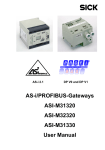
BWU1702, BWU1703, BWU2234
[1]
[2]
[3]
[4]
[5]
+
-
+
-
+
-
5 ... 6 mm / PZ2
0,8 Nm
7 LB.IN
10
2
2 x (0,5 ... 1,5) mm
10
2
2 x (0,5 ... 1,5) mm
AWG
2 x 24 ...12
Issue date: 28.3.2012
Legend:
[1]
LEDs
[2]
D-sub connection (PROFIBUS interface)
[3]
LC display
[4]
Push-buttons
[5]
AS-i and power supply terminal
Subject to technical modifications; no responsibility is accepted for the accuracy of this information
Internet: www.bihl-wiedemann.de • Flosswoerthstr. 41
• D-68199 Mannheim
© Bihl+Wiedemann GmbH
phone: +49 621 33 996-0 • fax: +49 621 3 39 22 399
31
AS-i 3.0 PROFIBUS Gateway in Stainless Steel
Electrical connection
7.1.3
BWU2544, BWU2545, BWU2546
[1]
[2]
[3]
[4]
[5]
[6]
+
-
+
-
+
-
[7]
5 ... 6 mm / PZ2
0,8 Nm
7 LB.IN
10
2
2 x (0,5 ... 1,5) mm
10
2
2 x (0,5 ... 1,5) mm
AWG
2 x 24 ...12
1.
32
Issue date: 28.3.2012
Legend:
[1]
Ethernet diagnostics port1
[2]
LEDs
[3]
D-sub connection (PROFIBUS interface)
[4]
LC display
[5]
Push-buttons
[6]
AS-i and power supply terminal
[7]
Chip card
Only in conjunction with AS-i Control Tools
Subject to technical modifications; no responsibility is accepted for the accuracy of this information
Internet: www.bihl-wiedemann.de
• Flosswoerthstr. 41
• D-68199 Mannheim
© Bihl+Wiedemann GmbH
phone: +49 621 33 996-0 • fax: +49 621 3 39 22 399
AS-i 3.0 PROFIBUS Gateway in Stainless Steel
Electrical connection
7.1.4
BWU1746
[2]
[1]
[3]
[4]
5 ... 6 mm / PZ2
0,8 Nm
7 LB.IN
10
2
2 x (0,5 ... 1,5) mm
10
2
2 x (0,5 ... 1,5) mm
[5]
AWG
2 x 24 ...12
Issue date: 28.3.2012
Legend:
[1]
D-sub connection (PROFIBUS interface)
[2]
LEDs
[3]
LED display (3-digit)
[4]
Push-buttons
[5]
AS-i and power supply terminal
Subject to technical modifications; no responsibility is accepted for the accuracy of this information
Internet: www.bihl-wiedemann.de • Flosswoerthstr. 41
• D-68199 Mannheim
© Bihl+Wiedemann GmbH
phone: +49 621 33 996-0 • fax: +49 621 3 39 22 399
33
AS-i 3.0 PROFIBUS Gateway in Stainless Steel
Electrical connection
7.2
AS-i bus connection
Blue
AS-i-
Blau
AS-i-
Brown
AS-i+
Yellow ASi ribbon cable
Braun
AS-i+
2-conductor AS-i round cable
(Recommended: flexible power cable
H05VV-F2x1,5 per DIN VDE 0281)
Information!
Electrical work is to be performed only by electrical technicians.
7.3
Information about the device types
Information!
A listing of the individual devices and their features can be found in section <Product
information>.
7.4
AS-i and power supply terminal assignments
Information!
The cable indicated by grey must not have slaves or repeaters connected to it.
The yellow cable must not have AS-i power suppliers or additional masters connected
to it.
Information!
The function ground can be connected either to the grounding screw or to the terminal.
The function ground should be made with as short a cable as possible to ensure good
EMC characteristics.
Therefore function grounding using the grounding screw is preferred.
Issue date: 28.3.2012
The AS-i communication can jam up if the connectors from a BWU2234 gateway are
exchanged with the ones from a BWU1702 gateway!
34
Subject to technical modifications; no responsibility is accepted for the accuracy of this information
Internet: www.bihl-wiedemann.de
• Flosswoerthstr. 41
• D-68199 Mannheim
© Bihl+Wiedemann GmbH
phone: +49 621 33 996-0 • fax: +49 621 3 39 22 399
AS-i 3.0 PROFIBUS Gateway in Stainless Steel
Electrical connection
7.4.1
Electrical connection BWU1567, BWU1775, BWU1599, BW1653,
BWU1773, BWU2544
M4
5 mm max!
+
-
+
-
+
-
+ASI –
Function ground
+ASI –
ASI +PWR– (max. 8A)
Terminal
Signal / Description
+AS-i–
ASI +PWR–
FE
Connection to AS-i Circuit
Supply voltage for AS-i Circuit (max. 8 A)
Function ground
Information!
Issue date: 28.3.2012
For additional information, please refer to the section <AS-i and power supply terminal
assignments>.
Subject to technical modifications; no responsibility is accepted for the accuracy of this information
Internet: www.bihl-wiedemann.de • Flosswoerthstr. 41
• D-68199 Mannheim
© Bihl+Wiedemann GmbH
phone: +49 621 33 996-0 • fax: +49 621 3 39 22 399
35
AS-i 3.0 PROFIBUS Gateway in Stainless Steel
Electrical connection
7.4.2
Electrical connection: BWU1702
M4
5 mm max!
Function ground
+
-
+
-
+
-
+ASI 1–
+ASI 1–
24V ext.
+
ASI 1 +PWR– (max. 4A)
Terminal
Signal / Description
+ASI–
Connection to AS-i Circuit
24 V ext.
Additional 24 V
ASI 1 +PWR–
Supply voltage for AS-i Circuit 1 (max. 4 A)
FG
Function ground
Information!
Issue date: 28.3.2012
For additional information, please refer to the section <AS-i and power supply terminal
assignments>.
36
Subject to technical modifications; no responsibility is accepted for the accuracy of this information
Internet: www.bihl-wiedemann.de
• Flosswoerthstr. 41
• D-68199 Mannheim
© Bihl+Wiedemann GmbH
phone: +49 621 33 996-0 • fax: +49 621 3 39 22 399
AS-i 3.0 PROFIBUS Gateway in Stainless Steel
Electrical connection
7.4.3
Electrical connection BWU1891
M4
5 mm max!
+
Function ground
-
+
-
+
-
+ASI –
+ASI –
ASI +PWR– (max. 4A)
Terminal
Signal / Description
+AS-i–
ASI +PWR–
FE
Connection to AS-i Circuit
Supply voltage for AS-i Circuit (max. 4 A)
Function ground
Information!
Issue date: 28.3.2012
For additional information, please refer to the section <AS-i and power supply terminal
assignments>.
Subject to technical modifications; no responsibility is accepted for the accuracy of this information
Internet: www.bihl-wiedemann.de • Flosswoerthstr. 41
• D-68199 Mannheim
© Bihl+Wiedemann GmbH
phone: +49 621 33 996-0 • fax: +49 621 3 39 22 399
37
AS-i 3.0 PROFIBUS Gateway in Stainless Steel
Electrical connection
7.4.4
Electrical connection BWU1568, BWU1776, BWU1600, BW1654,
BWU1703, BWU1774, BWU2545
M4
5 mm max!
+
-
+
-
+
-
+ASI 1–
Function ground
ASI 1 +PWR– (max. 8A)
+ASI 2–
+ 2 +PWR– (max. 8A)
ASI
Terminal
Signal / Description
+ASI 1–
Connection to AS-i circuit 1
+ASI 2–
Connection to AS-i circuit 2
ASI 1 +PWR–
Supply voltage for AS-i circuit 1 (max. 8 A)
ASI 2 +PWR–
Supply voltage for AS-i circuit 2 (max. 8 A)
FE
Function ground
Information!
AS-i circuits 1 and 2 are powered by separate power supplies.
Information!
Issue date: 28.3.2012
For additional information, please refer to the section <AS-i and power supply terminal
assignments>.
38
Subject to technical modifications; no responsibility is accepted for the accuracy of this information
Internet: www.bihl-wiedemann.de
• Flosswoerthstr. 41
• D-68199 Mannheim
© Bihl+Wiedemann GmbH
phone: +49 621 33 996-0 • fax: +49 621 3 39 22 399
AS-i 3.0 PROFIBUS Gateway in Stainless Steel
Electrical connection
7.4.5
Electrical connection BWU1569, BWU1777, BWU1601, BW1655,
BWU2234, BWU2546
+ASI1-
M4
5 mm max!
+
-
+ASI1-
+
ASI
+ASI2- +PWR-
-
+
-
+ASI 1–
Function ground
+ASI 1–
+ASI 2–
+ SI +PWR– (max. 8 A)
A
Terminal
Signal / Description
+ASI 1–
Connection to AS-i circuit 1
+ASI 2–
Connection to AS-i circuit 2
ASI +PWR–
Supply voltage for AS-i circuits (max. 8 A)
FE
Function ground
Information!
AS-i Circuit 1 and 2 are both powered from a Bihl+Wiedemann GmbH power supply!
No other power supplies are approved!
Information!
Issue date: 28.3.2012
For additional information, please refer to the section <AS-i and power supply terminal
assignments>.
Subject to technical modifications; no responsibility is accepted for the accuracy of this information
Internet: www.bihl-wiedemann.de • Flosswoerthstr. 41
• D-68199 Mannheim
© Bihl+Wiedemann GmbH
phone: +49 621 33 996-0 • fax: +49 621 3 39 22 399
39
AS-i 3.0 PROFIBUS Gateway in Stainless Steel
Electrical connection
7.4.6
Electrical connection BWU1746
Mode
+ ASI -
+
-
+ ASI -
+
-
Set
ASI
+ PWR -
+
-
Function ground
+ASI –
+ASI –
ASI +PWR– (max. 8A)
Terminal
+AS-i–
ASI +PWR–
FE
Signal / Description
Connection to AS-i Circuit
Supply voltage for AS-i Circuit (max. 8 A)
Function ground
Information!
Issue date: 28.3.2012
For additional information, please refer to the section <AS-i and power supply terminal
assignments>.
40
Subject to technical modifications; no responsibility is accepted for the accuracy of this information
Internet: www.bihl-wiedemann.de
• Flosswoerthstr. 41
• D-68199 Mannheim
© Bihl+Wiedemann GmbH
phone: +49 621 33 996-0 • fax: +49 621 3 39 22 399
AS-i 3.0 PROFIBUS Gateway in Stainless Steel
Electrical connection
7.5
PROFIBUS interface
The PROFIBUS interface is designed as a 9-pin D-SUB connector, in accordance
with the PROFIBUS standard EN 50 170. It is located at the top left-hand side of
the master.
.
DGND (0 Volt) PIN
9
8
7
6
5
4
3
2
1
RxD/TxD-N
(data line A)
RxD/TxD-P
(data line B)
VP / +5 Volt)
PROFIBUS
Designation of the D-SUB
connector
Pin 3
Pin 5
Pin 6
Pin 8
Data line B („RxD/TxD-P“)
DGND (0 V)
VP / +5 V
Data line A („RxD/TxD-N“)
The AS-i/PROFIBUS gateway sends and receives signals on pins 3 and 8 of the
D-SUB connector. The PROFIBUS signal “RxD/TxD-N (data line A)1” is located
on pin 8, the signal “RxD/TxD-P (data line B)1” is located on pin 3.
Pin 5 (0 V) and pin 6 (5 V) supply 5 V DC for the bus termination resistor.
7.5.1
Terminating resistors on the PROFIBUS network
5V
5V
390 Ω
390 Ω
A
A
A
220 Ω
220 Ω
B
B
B
390 Ω
390 Ω
GND
GND
Issue date: 28.3.2012
Host
AS-i Master
AS-i Master
1.
If you measure the DC voltage between RxD/TxD-P (data line B) and RxD/TxD-N (data line A),
RxD/TxD-P (data line B) is the positive pole when the bus is silent.
Subject to technical modifications; no responsibility is accepted for the accuracy of this information
Internet: www.bihl-wiedemann.de • Flosswoerthstr. 41
• D-68199 Mannheim
© Bihl+Wiedemann GmbH
phone: +49 621 33 996-0 • fax: +49 621 3 39 22 399
41
AS-i 3.0 PROFIBUS Gateway in Stainless Steel
Electrical connection
7.6
Diagnostics interface
The service and diagnostics interface (in conjunction with AS-i Control Tools
software) is used for communication between the PC and the unit.
7.6.1
BWU1567, BWU1775, BWU1599, BW1653, BWU1773, BWU1891,
BWU1568, BWU1776, BWU1600, BW1654, BWU1774, BWU1569,
BWU1777, BWU1601, BW1655
The service and diagnostics interface is configured as a mini DIN-6 female and it
is placed at the top of the housing (see section <Overview of terminals, indicators
and operating elements>).
7.6.2
BWU2544, BWU2545, BWU2546
The service and diagnostics interface in these devices is as RJ45 female configured and it is placed on the front plate, on the left hand side.
7.7
Chip card
The configuration is stored in a fixed installed EEPROM and can be overwritten
by the chip card. The chip card does not have to be inserted in operation.
Warning!
Power must always be turned off when removing or inserting the chip card!
7.7.1
Using the chip card
Issue date: 28.3.2012
The chip card integrated in the AS-i master is used to read-out and to store configuration data.
42
Subject to technical modifications; no responsibility is accepted for the accuracy of this information
Internet: www.bihl-wiedemann.de
• Flosswoerthstr. 41
• D-68199 Mannheim
© Bihl+Wiedemann GmbH
phone: +49 621 33 996-0 • fax: +49 621 3 39 22 399
AS-i 3.0 PROFIBUS Gateway in Stainless Steel
Electrical connection
7.7.1.1
Card unformatted
If an unformatted card is found when the device is started, the following is displayed:
NEW CHIPCARD
WILL BE FORMATED
AS-I DATA WILL
BE SYNCHRONIZED
The chip card is formatted and then the data copied to the chip card.
7.7.1.2
Data not compatible
If a card is found whose data are incompatible with the device, the following error
message is displayed:
CHIPCARD NOT
COMPATIBLE
7.7.1.3
Card empty
The following message is displayed for an empty card:
CHIPCARD FOUND
AS-I DATA WILL
BE SYNCHRONIZED
From this time on all changes are made both in the device and on the chip card.
7.7.1.4
Data compatible
When starting with an empty device (e.g. after a factory reset) a non-empty card
is found whose data are compatible with the device, the following message is displayed:
Issue date: 28.3.2012
AS-I DATA FROM
CHIPCARD TAKEN
The card configuration is written to the device. From this time on all changes are
made both in the device and on the chip card.
Subject to technical modifications; no responsibility is accepted for the accuracy of this information
Internet: www.bihl-wiedemann.de • Flosswoerthstr. 41
• D-68199 Mannheim
© Bihl+Wiedemann GmbH
phone: +49 621 33 996-0 • fax: +49 621 3 39 22 399
43
AS-i 3.0 PROFIBUS Gateway in Stainless Steel
Electrical connection
7.7.1.5
Data in the device and on the chip card identical
If the card and device are not empty at start and the data are identical, no message is displayed.
7.7.1.6
Data in the device and on the chip card not identical
If the card and device are not empty at start and the data are not identical, an error message is displayed and the card is not synchronized with the device. The
following menu is then automatically opened:
CHIPCARD AND
AS-I DATA
DIFFERENT
CARD->MASTER
MASTER->CARD
CONTINUE
Description
CHIP CARD>MASTER: Chip card data are copied to the master
MASTER->CHIPCARD: Master data are copied to the chip card
NEXT: No change to the data
Issue date: 28.3.2012
The menu can be exited by pressing the ESC/Service key without changing the
data.
44
Subject to technical modifications; no responsibility is accepted for the accuracy of this information
Internet: www.bihl-wiedemann.de
• Flosswoerthstr. 41
• D-68199 Mannheim
© Bihl+Wiedemann GmbH
phone: +49 621 33 996-0 • fax: +49 621 3 39 22 399
AS-i 3.0 PROFIBUS Gateway in Stainless Steel
Electrical connection
Indicators and operating elements
7.8.1
LED indicators – master
PR
O
FI
BU
S
7.8
The LED’s on the front panel of the device indicate:
Power
The master is receiving sufficient power.
PROFIBUS
LED an: Gateway is allocated to a PROFIBUS Master.
LED aus: Gateway is not allocated to a PROFIBUS Master.
config error
Configuration error.
At least one configured slave is missing, or at least one detected slave is not configured, or for at least one configured and detected slave the actual configuration data
does not match the nominal configuration data, or the master is in the startup process.
This LED flashes if a peripheral fault has been detected for at least one AS-i slave on
the AS-i network. If there are configuration errors as well as periphery faults, only the
configuration error is displayed.
U AS-i
The AS-i network is sufficiently powered.
AS-i active
Normal operation is active
prg enable
Automatic single node replacement is enabled.
Exactly one slave is missing in the protected operating mode. The slave can be
replaced by another slave of the same type with address zero. The master automatically addresses the new slave to the faulty address and thus corrects the configuration error
prj mode
Issue date: 28.3.2012
The AS-i master is in configuration mode.
Subject to technical modifications; no responsibility is accepted for the accuracy of this information
Internet: www.bihl-wiedemann.de • Flosswoerthstr. 41
• D-68199 Mannheim
© Bihl+Wiedemann GmbH
phone: +49 621 33 996-0 • fax: +49 621 3 39 22 399
45
AS-i 3.0 PROFIBUS Gateway in Stainless Steel
Electrical connection
7.8.2
Buttons
The buttons are used for the following:
Mode/⇑
Switching between configuration mode and protected operating mode, and saving
the current AS-i configuration as the nominal configuration.
Set/⇓
Selecting the address of and assigning an address to a slave.
OK, ESC
Changing to the advanced display mode.
Issue date: 28.3.2012
For additional information see section <Operation in advanced display mode>.
46
Subject to technical modifications; no responsibility is accepted for the accuracy of this information
Internet: www.bihl-wiedemann.de
• Flosswoerthstr. 41
• D-68199 Mannheim
© Bihl+Wiedemann GmbH
phone: +49 621 33 996-0 • fax: +49 621 3 39 22 399
AS-i 3.0 PROFIBUS Gateway in Stainless Steel
Operation in advanced display mode
8.
Operation in advanced display mode
Information!
You will find a description of the display menu in the separate document
Issue date: 28.3.2012
"Display_Menue".
47
Subject to technical modifications; no responsibility is accepted for the accuracy of this information
Internet: www.bihl-wiedemann.de
• Flosswoerthstr. 41
• D-68199 Mannheim
© Bihl+Wiedemann GmbH
phone: +49 621 33 996-0 • fax: +49 621 3 39 22 399
AS-i 3.0 PROFIBUS Gateway in Stainless Steel
PROFIBUS DP
9.
PROFIBUS DP
This chapter contains all necessary information to operate the PROFIBUS gateways in a PROFIBUS DP network.
Information!
The respective bits ground fault, overvoltage, noise, double address will only be set if
AS-i masters are used, which also support these functions.
9.1
DP Telegrams
9.1.1
Diagnostics
EC-flags (high) and AS-i watchdog:
bit 0:
periphery fault
bit 1:
…
bit 2:
failure redundant 24 V AUX (option safety monitor)
bit 3:
failure redundant 24 V AUX (option single master)
bit 4:
earth fault
bit 5:
over voltage
bit 6:
noise
bit 7:
duplicate address
EC-flags (low):
bit 0:
configuration error
bit 1:
slave with address ’0’ detected
bit 2:
auto_address_assignment not possible
bit 3:
auto_address_assignment available
bit 4:
configuration mode active
bit 5:
not in normal operation
bit 6:
AS-i power fail
bit 7:
AS-i master offline
1:
ConfigError
0:
no ConfigError
Issue date: 28.3.2012
Delta list: List of AS-i slaves with configuration error
LPF: List of AS-i slaves with periphery fault
48
1:
periphery fault
0:
no periphery fault
Subject to technical modifications; no responsibility is accepted for the accuracy of this information
Internet: www.bihl-wiedemann.de
• Flosswoerthstr. 41
• D-68199 Mannheim
© Bihl+Wiedemann GmbH
phone: +49 621 33 996-0 • fax: +49 621 3 39 22 399
AS-i 3.0 PROFIBUS Gateway in Stainless Steel
PROFIBUS DP
Each element of the user diagnostics (ec-flags and slave lists) can be switched
off by setting the appropriate bit in the parameter telegram.
ExtDiag will be set if at least one of the following conditions is fulfilled:
•
ConfigError ≡ 1
•
APF ≡ 1
•
PeripheryFault ≡ 1
The conditions when to set the ExtDiag bit can be chosen using the user parameters or the commands of the command interface.
The GSD file includes the following presettings:
•
The diagnosis transmitts ec-flags, delta list and LPF.
•
ExtDiag will be set if ConfigError = 1 and APF = 1. ExtDiag will not be set if
there is a periphery fault.
If a double master is being used, the data for AS-i circuit are transmitted in the
user parameter bytes 4 to 6. For circuit 2 3 additional bytes are added.
9.1.1.1
Diagnostic description for BWU1567, BWU1568, BWU1569,
BWU1599, BWU1600, BWU1601, BW1653, BW1654, BW1655,
BWU1702, BWU1703, BWU1746, BWU1773, BWU1774, BWU1775,
BWU1776, BWU1777, BWU1891, BWU2234
DP diagnostics - single master
Issue date: 28.3.2012
PDU byte
1
user byte
–
station_status 1
DP
4
DP/V1
2
–
station_status 2
4
3
–
station_status 3
4
4
–
master address
4
5
–
ident high
4
6
–
ident low
4
7
1
header
4
8
2
type
4
user
4
9
3
slot
4
10
4
spec
4
11
5
ec-flags (high)
4
12
6
ec-flags (low)
4
13
7
delta (0…7)
4
14
8
delta (8…15)
4
…
…
…
…
Tab. 9-2.
Subject to technical modifications; no responsibility is accepted for the accuracy of this information
Internet: www.bihl-wiedemann.de • Flosswoerthstr. 41
• D-68199 Mannheim
© Bihl+Wiedemann GmbH
phone: +49 621 33 996-0 • fax: +49 621 3 39 22 399
49
AS-i 3.0 PROFIBUS Gateway in Stainless Steel
PROFIBUS DP
DP diagnostics - single master
PDU byte
20
user byte
14
delta (56…63)
21
DP
DP/V1
user
4
15
LPF (0…7)
4
…
…
…
…
28
22
LPF (56 … 63)
4
Issue date: 28.3.2012
Tab. 9-2.
50
Subject to technical modifications; no responsibility is accepted for the accuracy of this information
Internet: www.bihl-wiedemann.de
• Flosswoerthstr. 41
• D-68199 Mannheim
© Bihl+Wiedemann GmbH
phone: +49 621 33 996-0 • fax: +49 621 3 39 22 399
AS-i 3.0 PROFIBUS Gateway in Stainless Steel
PROFIBUS DP
DP diagnostics - double master
Issue date: 28.3.2012
PDU byte
1
user byte
–
station_status 1
DP
4
DP/V1
user
2
–
station_status 2
4
3
–
station_status 3
4
4
–
master address
4
5
–
ident high
4
6
–
ident low
4
7
1
header
4
8
2
type
4
9
3
slot
4
10
4
spec
4
11
5
ec-flags (high), circuit 1
4
12
6
ec-flags (low), circuit 1
4
13
7
delta (0 … 7), circuit 1
4
14
8
delta (8 … 15), circuit 1
4
4
…
…
…
…
20
14
delta (56 … 63), circuit 1
4
21
15
LPF (0 … 7), circuit 1
4
…
…
…
…
28
22
LPF (56 … 63), circuit 1
4
29
23
reserved
4
…
…
…
…
36
30
reserved
4
37
31
ec-flags (high), circuit 2
4
38
32
ec-flags (low), circuit 2
4
39
33
delta (0…7), circuit 2
4
40
34
delta (8…15), circuit 2
4
…
…
…
…
46
40
delta (56…63), circuit 2
4
47
41
LPF (0…7), circuit 2
4
…
…
…
48
LPF (56 … 63), circuit 2
54
4
Tab. 9-3.
Subject to technical modifications; no responsibility is accepted for the accuracy of this information
Internet: www.bihl-wiedemann.de • Flosswoerthstr. 41
• D-68199 Mannheim
© Bihl+Wiedemann GmbH
phone: +49 621 33 996-0 • fax: +49 621 3 39 22 399
51
AS-i 3.0 PROFIBUS Gateway in Stainless Steel
PROFIBUS DP
9.1.1.2
Diagnostic description for BWU2544, BWU2545, BWU2546
DP diagnostics
Byte
description
1
station state 1
2
station state 2
3
station state 3
4
Master address
5
ident high
6
ident low
Tab. 9-4.
The following blocks may be optionally appended to the DP diagnostics. Bytes
1 … 4 are sent in each block according to the PROFIBUS standard.
Only when double masters are used is the entry „circuit 2“ available in the AS-i
flags, delta list and LPF.
AS-i flags
Byte
description
1
0x06 header
2
0xA0 (circuit 1)/0xA1 (circuit 2) type
3
0x00 slot
4
0x00 spec
5
EC flags (high)
6
EC flags (low)
Tab. 9-5.
Byte
description
1
0x0C header
2
0xA2 (circuit 1)/0xA3 (circuit 2) type
3
0x00 slot
4
0x00 spec
5
delta (0 … 7)
6
delta (8 … 15)
Tab. 9-6.
52
Subject to technical modifications; no responsibility is accepted for the accuracy of this information
Internet: www.bihl-wiedemann.de
• Flosswoerthstr. 41
• D-68199 Mannheim
© Bihl+Wiedemann GmbH
phone: +49 621 33 996-0 • fax: +49 621 3 39 22 399
Issue date: 28.3.2012
Delta list
AS-i 3.0 PROFIBUS Gateway in Stainless Steel
PROFIBUS DP
Delta list
Byte
description
…
…
12
delta (56 … 63)
Tab. 9-6.
LPF
Byte
description
1
0x0C header
2
0xA4 (circuit 1)/0xA5 (circuit 2) type
3
0x00 slot
4
0x00 spec
5
LPF (0 ... 7)
6
LPF (8 ... 15)
…
…
12
LPF (56 … 63)
Tab. 9-7.
9.1.1.3
Parameters
With the user parameters you can choose if and which slave list will be displayed
in the diagnosis. Furthermore you can select which conditions have to be fulfilled
to set the ExtDiag bit within the diagnostic telegram.
DP parameters - single master
Issue date: 28.3.2012
PDU byte
1
user byte
–
Station_Status
DP
4
DP/V1
user
default
2
–
WD_Fact_1
4
3
–
WD_Fact_2
4
4
–
min Tsdr
4
5
–
Ident High
4
6
–
Ident Low
4
7
–
Group_Ident
4
8
1
DPV Status 1
4
8016
9
2
DPV Status 2
4
0016
10
3
DPV Status 3
4
0016
Tab. 9-8.
Subject to technical modifications; no responsibility is accepted for the accuracy of this information
Internet: www.bihl-wiedemann.de • Flosswoerthstr. 41
• D-68199 Mannheim
© Bihl+Wiedemann GmbH
phone: +49 621 33 996-0 • fax: +49 621 3 39 22 399
53
AS-i 3.0 PROFIBUS Gateway in Stainless Steel
PROFIBUS DP
DP parameters - single master
PDU byte
11
user byte
4
User Byte 1
DP
DP/V1
user
4
default
0B16
12
5
User Byte 2
4
0616
13
6
User Byte 3
4
0016
Tab. 9-8.
DP parameters - double master
PDU byte
1
user byte
–
Station_Status
DP
4
DP/V1
user
default
2
–
WD_Fact_1
4
3
–
WD_Fact_2
4
4
–
min Tsdr
4
5
–
ident high
4
6
–
ident low
4
7
–
Group_Ident
4
8
1
DPV status 1
4
8016
9
2
DPV status 2
4
0016
10
3
DPV status 3
4
0016
11
4
user byte 1, circuit 1
4
0B16
12
5
user byte 2, circuit 1
4
0616
13
6
user byte 3, circuit 1
4
0016
14
7
user byte 1, circuit 2
4
0B16
15
8
user byte 2, circuit 2
4
0616
16
9
user byte 3, circuit 2
4
0016
Tab. 9-9.
The bits in "user byte 1" and "user byte 3" have the following meanings:
user byte 1
default
27
0
26
25
24
0
0
23
LPF
1
22
–
0
21
D
1
20
F
1
Issue date: 28.3.2012
Tab. 9-10.
The GSD's default user parameter telegram is:
(DP/V1 enabled, diagnostics settings see chap. <Diagnostics>).
54
Subject to technical modifications; no responsibility is accepted for the accuracy of this information
Internet: www.bihl-wiedemann.de
• Flosswoerthstr. 41
• D-68199 Mannheim
© Bihl+Wiedemann GmbH
phone: +49 621 33 996-0 • fax: +49 621 3 39 22 399
AS-i 3.0 PROFIBUS Gateway in Stainless Steel
PROFIBUS DP
user byte 2
default
27
FD
0
26
25
0
0
24
CS
0
23
PF
0
22
APF
1
21
CF
1
20
–
0
Tab. 9-11.
user byte 3
27
26
25
24
23
22
–
0
default
21
20
0
0
Tab. 9-12.
LPF:
1:
LPF will be transmitted in the diagnostics
0:
LPF will not be transmitted
1:
Delta list will be transmitted in the diagnostics
0:
Delta list will not be transmitted
1:
EC-flags will be transmitted in the diagnostics
0:
EC-flags will not be transmitted
D:
F:
FD:
If this bit is set, the PROFIBUS diagnostics is refreshed only if the
PROFIBUS norm dictates this ("freeze diagnostics"). In doubt the
data of the PROFIBUS masters diagnostics are not up to date.
CS:
1:
ExtDiag will be set if the LCS is not empty
0:
ExtDiag will not be set if the LCS is not empty
1:
ExtDiag will be set if there is a periphery fault at the AS-i line
0:
ExtDiag will not be set.
1:
ExtDiag will be set if there is an AS-i power fail
0:
ExtDiag will not be set.
1:
ExtDiag will be set if there is a configuration error
0:
ExtDiag will not be set.
PF:
APF:
Issue date: 28.3.2012
CF:
8016
0016
0016
0B16
0616
Subject to technical modifications; no responsibility is accepted for the accuracy of this information
Internet: www.bihl-wiedemann.de • Flosswoerthstr. 41
• D-68199 Mannheim
0016
© Bihl+Wiedemann GmbH
phone: +49 621 33 996-0 • fax: +49 621 3 39 22 399
55
AS-i 3.0 PROFIBUS Gateway in Stainless Steel
PROFIBUS DP
If a double master is being used, the User-Diagnosis-Bytes 5 to 30 represent
AS-i network 1 and the User-diagnosis bytes 31 to 48 represent AS-i network 2.
9.1.2
Configuration DP/V0 (cyclic data)
The configuration of the AS-i/PROFIBUS gateways is made with the GSD file.
Therefore the provided GSD file has to be imported into your PROFIBUS configuration tool.
9.1.2.1
Options
The original data input and outlet data can be used with different „Special IDs“.
The advantages of special input and output IDs are, that they can include up to
64 elements (bytes or words), and that the length of input and output data can be
different. Additionally, "manufacturer specific" data bytes describing the ID type
are possible. These "manufacturer specific" data bytes describe the which type ID
is.
The GSD file offers here several combinations (several lengths) for transmitting
I/O date, command interface (management) and analog data.
Therefore the analog data can be transmitted directly in the process data channel
and do not have to be requested by the slower DP/V1 commands.
Maximally 8 modules can be configurated.
Information!
There are some controls, with which slot numbers (1-n) required for generating of new
modules are not generated automatically, but must be added manually!
The detailed possibilities:
Length
description
4 bytes
digital input (slaves 0 - 7)
8 bytes
digital input (slaves 0 - 15)
12 bytes
digital input (slaves 0 - 23)
16 bytes
digital input (slaves 0 - 31)
20 bytes
digital input (slaves 0 - 7B)
24 bytes
digital input (slaves 0 - 15B)
28 bytes
digital input (slaves 0 - 23B)
32 bytes
digital input (slaves 0 - 31B)
Length
description
4 bytes
digital output (slaves 0 - 7)
8 bytes
digital output (slaves 0 - 15)
Tab. 9-14.
56
Subject to technical modifications; no responsibility is accepted for the accuracy of this information
Internet: www.bihl-wiedemann.de
• Flosswoerthstr. 41
• D-68199 Mannheim
© Bihl+Wiedemann GmbH
phone: +49 621 33 996-0 • fax: +49 621 3 39 22 399
Issue date: 28.3.2012
Tab. 9-13.
AS-i 3.0 PROFIBUS Gateway in Stainless Steel
PROFIBUS DP
Length
description
12 bytes
digital output (slaves 0 - 23)
16 bytes
digital output (slaves 0 - 31)
20 bytes
digital output (slaves 0 - 7B)
24 bytes
digital output (slaves 0 - 15B)
28 bytes
digital output (slaves 0 - 23B)
32 bytes
digital output (slaves 0 - 31B)
Tab. 9-14.
Length
description
16 bytes
digital in/out (slaves 0 - 31)
16 Bytes
digital in/out (slaves 0B - 31B)
32 bytes
digital in/out (slaves 0 - 31B)
Tab. 9-15.
Information!
2 command interfaces can be intergrated.
Length
description
2 bytes
management (command interface)
4 bytes
management (command interface)
8 bytes
management (command interface)
11 bytes
management (command interface)
12 bytes
management (command interface)
34 bytes
management (command interface)
36 bytes
management (command interface)
Issue date: 28.3.2012
Tab. 9-16.
Length
description
24 bytes
analog input (slaves 29 - 31)
56 bytes
analog input (slaves 25 - 31)
88 bytes
analog input (slaves 21 - 31)
120 bytes
analog input (slaves 17 - 31)
128 bytes
analog input (slaves 16 - 31)
16 bytes
analog input (slaves 14 - 15)
Tab. 9-17.
Subject to technical modifications; no responsibility is accepted for the accuracy of this information
Internet: www.bihl-wiedemann.de • Flosswoerthstr. 41
• D-68199 Mannheim
© Bihl+Wiedemann GmbH
phone: +49 621 33 996-0 • fax: +49 621 3 39 22 399
57
AS-i 3.0 PROFIBUS Gateway in Stainless Steel
PROFIBUS DP
Length
description
24 bytes
analog output (slaves 29 - 31)
56 bytes
analog output (slaves 25 - 31)
88 bytes
analog output (slaves 21 - 31)
120 bytes
analog output (slaves 17 - 31)
128 bytes
analog output (slaves 16 - 31)
16 bytes
analog output (slaves 14 - 15)
Tab. 9-18.
Length
description
2 bytes … 128 bytes
analog input data circuit 1, dynamic1
2 bytes … 128 bytes
analog output data circuit 1, dynamic1
2 bytes … 128 bytes
analog input data circuit 2, dynamic1
2 bytes … 128 bytes
analog output data circuit 2, dynamic1
Tab. 9-19.
1. Module parameters necessarily
Length
description
2 bytes
flags and detector circuit 1
2 bytes
flags and detector circuit 2
Tab. 9-20.
9.1.3
I/O Data
9.1.3.1
Process data
In V2.1 mode the AS-i I/O data are mapped in the process data as known from
the Siemens and AS-i/InterBus masters. This means that the lower nibble describes the data of the AS-i slave with the higher slave address. The ec-flags or
hi-flags are additionally mapped at the nibble of AS-i slave 0.
27
0
F3
1
2
3
4
5
6
7
8
26
25
flags
F2
F1
slave 2/2A
slave 4/4A
slave 6/6A
slave 8/8A
slave 10/10A
slave 12/12A
slave 14/14A
slave 16/16A
24
23
F0
D3
22
21
slave 1/1A
D2
D1
slave 3/3A
slave 5/5A
slave 7/7A
slave 9/9A
slave 11/11A
slave 13/13A
slave 15/15A
slave 17/17A
20
D0
Tab. 9-21.
58
Subject to technical modifications; no responsibility is accepted for the accuracy of this information
Internet: www.bihl-wiedemann.de
• Flosswoerthstr. 41
• D-68199 Mannheim
© Bihl+Wiedemann GmbH
phone: +49 621 33 996-0 • fax: +49 621 3 39 22 399
Issue date: 28.3.2012
byte
AS-i 3.0 PROFIBUS Gateway in Stainless Steel
PROFIBUS DP
byte
27
9
10
11
12
13
14
15
16
17
18
19
20
21
22
23
24
25
26
27
28
29
30
31
26
25
slave 18/18A
slave 20/20A
slave 22/22A
slave 24/24A
slave 26/26A
slave 28/28A
slave 30/30A
reserved
slave 2B
slave 4B
slave 6B
slave 8B
slave 10B
slave 12B
slave 14B
slave 16B
slave 18B
slave 20B
slave 22B
slave 24B
slave 26B
slave 28B
slave 30B
24
23
22
21
slave 19/19A
slave 21/21A
slave 23/23A
slave 25/25A
slave 27/27A
slave 29/29A
slave 31/31A
slave 1B
slave 3B
slave 5B
slave 7B
slave 9B
slave 11B
slave 13B
slave 15B
slave 17B
slave 19B
slave 21B
slave 23B
slave 25B
slave 27B
slave 29B
slave 31B
20
Tab. 9-21.
Flags
input data
output data
F0
ConfigError
Offline
F1
APF
LOS master bit
F2
PeripheryFault
→ ConfigurationMode
F3
ConfigurationActive
→ ProtectedMode
Tab. 9-22.
Issue date: 28.3.2012
ConfigError:
0 = config ok
1 = config error
APF:
0 = AS-i power ok
1 = AS-i power fail
PeripheryFault:
0 = periphery ok
1 = periphery fault
ConfigurationActive:
0 = configuration active
1 = configuration inactive
Subject to technical modifications; no responsibility is accepted for the accuracy of this information
Internet: www.bihl-wiedemann.de • Flosswoerthstr. 41
• D-68199 Mannheim
© Bihl+Wiedemann GmbH
phone: +49 621 33 996-0 • fax: +49 621 3 39 22 399
59
AS-i 3.0 PROFIBUS Gateway in Stainless Steel
PROFIBUS DP
Offline:
LOS-Master-Bit
0 = online
1 = offline
0 = offline by configerror deactivated
1 = offline by configerror activated
A rising edge of F2 and F3 switch the master to the desired mode.
A rising edge of the "LOS master bit" effects that all bits in the LOS are set. A falling edge effects that all bits are deleted.
EC-flags (high) and AS-i watchdog:
bit 0:
periphery fault
bit 1:
…
bit 2:
failure redundant 24 V AUX (option safety monitor)
bit 3:
failure redundant 24 V AUX (option single master)
bit 4:
earth fault
bit 5:
over voltage
bit 6:
noise
bit 7:
duplicate address
EC-flags (low):
9.1.3.2
bit 0:
configuration error
bit 1:
slave with address ’0’ detected
bit 2:
auto_address_assignment not possible
bit 3:
auto_address_assignment available
bit 4:
configuration mode active
bit 5:
not in normal operation
bit 6:
AS-i power fail
bit 7:
AS-i master offline
AS-i 16-bit data
Information!
A-slaves map the data on channels 1 and 2.
In addition to the access via the command interfaces, the 16-bit data for or by the
slaves with 16-bit value can by exchanged cyclically (profile 7.3., S-7.4, S-6.0, S7.5, S-7.A.8, S-7.A.9, S-7.A.A). Competing writing access attempts on analog
output data will not be blocked by each other. If analog data for a particular slave
60
Subject to technical modifications; no responsibility is accepted for the accuracy of this information
Internet: www.bihl-wiedemann.de
• Flosswoerthstr. 41
• D-68199 Mannheim
© Bihl+Wiedemann GmbH
phone: +49 621 33 996-0 • fax: +49 621 3 39 22 399
Issue date: 28.3.2012
B-slaves map the data on channels 3 and 4.
AS-i 3.0 PROFIBUS Gateway in Stainless Steel
PROFIBUS DP
are being transmitted both cyclically and acyclically with the command interface
or via DP/V1 connections, the acyclically transmitted values will be overwritten by
the cyclically transmitted values.
AS-i 16-bit data can be transmitted in a reserved data area. Therefore accessing
analog data is as easy as accessing digital data.
16-bit data
byte
27
1
2
3
4
…
n-3
n-2
n-1
n
26
25
24
23
22
21
slave 31-n/8, channel 1, high byte
slave 31-n/8, channel 1, low byte
slave 31-n/8, channel 2, high byte
slave 31-n/8, channel 2, low byte
…
slave 31, channel 3/slave 31B, channel 1, high byte
slave 31, channel 3/slave 31B, channel 1, low byte
slave 31, channel 4/slave 31B, channel 2, high byte
slave 31, channel 4/slave 31B, channel 2, low byte
20
Tab. 9-23.
9.1.3.3
Command interface
Only using the IDs of the process data field the PROFIBUS gateway can be used
as M0 AS-i master. By using the command interface (see chap. <DP/V1>) the
functions of a M3 master become available.
Request
byte
1
2
3
…
36
27
26
25
24
23
22
command
circuit
request parameter byte 1
…
request parameter byte 34
21
20
26
25
24
23
22
command (mirrored)
result
response parameter byte 1
…
response parameter byte 34
21
20
T
Answer
byte
27
Issue date: 28.3.2012
1
2
3
…
36
Tab. 9-24.
A command of the command interface will be edited if the toggle bit T1 has
changed. This way the same command can be used repeatedly.
Subject to technical modifications; no responsibility is accepted for the accuracy of this information
Internet: www.bihl-wiedemann.de • Flosswoerthstr. 41
• D-68199 Mannheim
© Bihl+Wiedemann GmbH
phone: +49 621 33 996-0 • fax: +49 621 3 39 22 399
61
AS-i 3.0 PROFIBUS Gateway in Stainless Steel
PROFIBUS DP
The commands of the command interface can also be activated with PROFIBUS
DP/V1. Even the process data exchange is possible via the command interface.
This way the Windows configuration software "AS-i-Control Tools" can run the
whole communication via DP/V1.
9.1.3.4
Safety Control/Status
In the fieldbus configuration the designator Safety Control/Status can be added
as cyclical data. This is possible both for the integrated Safety Monitor and for
2nd generation Monitors.
Information!
Generation III external Monitors allow a maximum of eight OSSDs to be sent.
The state of the outputs and the message outputs is then inserted as a cyclical input datum.
Inputs
byte
1
description
Status OSSD 1, color-coded as defined in the table <Coding of status bytes>).
2
Status OSSD 2, color-coded as defined in the table <Coding of status bytes>).
…
…
n
Status OSSD n, color-coded as defined in the table <Coding of status bytes>).
Tab. 9-25.
Bit [0 ... 3]
state or. color
description
0016
green permanent lighting
output on
0116
green flashing
delay time is running at stop category 1
0216
yellow permanent lighting start-up/restart-disable active
0316
yellow flashing
external test necessary / acknowledgement / start delay active
0416
red permanent lighting
output off
0516
red flashing
error
0616
grey or off
output not projected
0716
reserved
Bit [6]
status or color
Tab. 9-26.
1. A T bit (toggle bit) is only needed to execute two commands directly one after the other.
62
Subject to technical modifications; no responsibility is accepted for the accuracy of this information
Internet: www.bihl-wiedemann.de
• Flosswoerthstr. 41
• D-68199 Mannheim
© Bihl+Wiedemann GmbH
phone: +49 621 33 996-0 • fax: +49 621 3 39 22 399
Issue date: 28.3.2012
Coding of status bytes
AS-i 3.0 PROFIBUS Gateway in Stainless Steel
PROFIBUS DP
Coding of status bytes
0
no device flashing yellow
1
at least one device flashing yellow
Bit [7]
status or color
0
no device flashing red
1
at least one device flashing red
Tab. 9-26.
The cyclical output identifier contains the 4 Safety Monitor bits 1.Y1, 1.Y2, 2.Y1
and 2.Y2. The monitoring element “Monitor input” and the start elements “Monitor
Start-Monitor Input” and “Activation using Monitor Input” access these data. In
contrast, the “Feedback circuit” element always accesses the EDM input.
Outputs
byte description
1 byte from the fieldbus
bit 0: 1.Y1
bit 1: 1.Y2
bit 2: 2.Y1
bit 3: 2.Y2
bit 4 ... 7: reserved
2 reserved
Tab. 9-27.
The bits of the output bytes are ORed with the real and the homonymous hardware inputs of the device.
9.2
DP/V1
To exchange data between the PROFIBUS master and the AS-i/PROFIBUS gateway via PROFIBUS DP/V1 only one data block is used - slot 1, index 16. Within
this data block a command interface is installed like the one used in the DP telegram.
The DP/V1-command interfaces are edited every time they are sent. Therefore it
is possible to execute the same command several times without changing "command" or "circuit" and setting a toggle bit.
Issue date: 28.3.2012
9.3
Restrictions
The SPC3 has only 1,5 KByte DP-RAM available. Therefore the lengths of telegrams and the numbers of DP/V1-connections to class 2 masters have to be restricted.
Subject to technical modifications; no responsibility is accepted for the accuracy of this information
Internet: www.bihl-wiedemann.de • Flosswoerthstr. 41
• D-68199 Mannheim
© Bihl+Wiedemann GmbH
phone: +49 621 33 996-0 • fax: +49 621 3 39 22 399
63
AS-i 3.0 PROFIBUS Gateway in Stainless Steel
PROFIBUS DP
Information!
I+M service contains data for identification and maintenance. This service is on by
default. Switching the services off provides additional memory into SPC3. This
changes the DP/VD length-limit.
Restrictions due to the SPC3
MSC1
MSAC1
MSAC2
inputs data / outputs single master: 288 bytes1
data
doppel master: 272 bytes2
diagnosis
62 bytes
parameter
single master: 53 bytes
doppel master: 88 bytes
configuration3
32 bytes
SetSlaveAddress
4 bytes
SAPs
PDU
1
SAPs
PDU
2
72 bytes4
72 bytes5
Tab. 9-28.
Issue date: 28.3.2012
1.
The maximum length of the input and output data can vary up to 288 bytes input or output data if
the I+M (information+maintenance) service is on only. The maximum length of the input and output data (both
master) is not variable and it is limited to 144 bytes (for input and output data) if the I+M service is disabled.
2.
The maximum length of the input and output data can vary up to 272 bytes input or output data if
the I+M (information+maintenance) service is on only. The maximum length of the input and output data (both
master) is not variable and it is limited to 144 bytes (for input and output data) if the I+M service is disabled.
3.
Maximally 8 modules can be configurated
4.
The maximum length is limited to 42 bytes if the I+M service is set to off.
5.
The maximum length is limited to 52 bytes if the I+M service is set to off.
64
Subject to technical modifications; no responsibility is accepted for the accuracy of this information
Internet: www.bihl-wiedemann.de
• Flosswoerthstr. 41
• D-68199 Mannheim
© Bihl+Wiedemann GmbH
phone: +49 621 33 996-0 • fax: +49 621 3 39 22 399
AS-i 3.0 PROFIBUS Gateway in Stainless Steel
Advanced Diagnostics for AS-i Masters
10.
Advanced Diagnostics for AS-i Masters
The advanced AS-i diagnostics is intended to localize occasionally occurring configuration errors and to determine the quality of data transmission on AS-i without
using additional diagnostics tools.
AS-i Control Tools, a MS-Windows software designed to simplify AS-i installation
and used to program AS-i Control, enables operation of the advanced diagnostics
functions (LCS, error counters, and LOS).
10.1
List of corrupted AS-i Slaves (LCS)
The LCS contains the information from the Delta list. In addition to the list of configured slaves (LPS), the list of detected slaves (LDS), and the list of activated
slaves (LAS), the AS-i master creates a fourth list, the list of corrupted slaves
(LCS) containing advanced diagnostics data used to diagnose the causes for intermittently occurring configuration errors on AS-i. This list contains entries for all
AS-i slaves that were responsible for at least one intermittent configuration error
since the list was last read or since the AS-i master was turned on. Furthermore,
intermittent AS-i power failures are listed in the LCS at the position of AS-i slave
with address 0.
Information!
Whenever the LCS is read it is deleted from memory.
Information!
The last intermittent configuration error can also be displayed on the AS-i master:
Pressing the "Set" button on the AS-i master initiates the display of the AS-i slave
responsible for the last intermittent configuration error. If a intermittent AS-i power failure occurred, the display shows 39 after pressing the "Set" button.
This function is only available if the device is in normal operating mode of the protected
mode (display empty) or in the off-line phase (Display: "40").
10.2
Protocol analysis: Counters for corrupted data telegrams
The AS-i master with advanced diagnostics provides a counter for telegram repetitions for each AS-i slave. The counter counts up every time a corrupted data
telegram has been found, making it possible to determine the quality of the transmission if only a few telegrams are corrupt and the AS-i slave never caused a
configuration error.
Information!
The counter values are read via the host interface and will be deleted after they were
read.
Displaying the protocol analysis is possible through the AS-i Control Tools software by using the command "Master | AS-i Diagnostics".
65
Subject to technical modifications; no responsibility is accepted for the accuracy of this information
Internet: www.bihl-wiedemann.de
• Flosswoerthstr. 41
• D-68199 Mannheim
© Bihl+Wiedemann GmbH
phone: +49 621 33 996-0 • fax: +49 621 3 39 22 399
Issue date: 28.3.2012
The highest possible counter value is 254. 255 indicates a counter overflow.
AS-i 3.0 PROFIBUS Gateway in Stainless Steel
Advanced Diagnostics for AS-i Masters
10.3
Offline Phase for Configuration Errors
The AS-i masters with advanced diagnostics offer the possibility to set themselves into the offline phase when a configuration error occurs and thus are able
to transition the AS-i network into a safe operational state. This ensures a quick
reaction to a configuration error and the host can be relieved from this task. If any
problems occur on the AS-i network, the AS-i masters can independently switch
the AS-interface into a safe state.
There are two different ways to parameterize the AS-i master for this feature:
•
Any configuration error occurring on AS-i switches the master from regular
operation in protected mode into the offline phase.
•
o . A list with the addresses of slaves that can potential initiate the off-line
phase is defined (list of offline slaves LOS).
The user can decide how the system should react to a configuration error on
AS-i. Thus, the AS-i master can be set to the offline phase for critical AS-i slaves,
whereas for less critical slaves only the error message is sent to the host, but
AS-i is still running.
Like the advanced diagnostics, the parameterization "offline phase on configuration error" is also supported by "AS-i-Control-Tools"
(Command | Characteristics | Offline because of configuration error).
There are two options to reset the error message "OFFLINE BY LOS:
1.
Deleting the complete LOS list on the affected AS-i network ("CLEAR ALL").
2.
Power reset on the affected AS-i network.
Attention!
If a power reset occurs on the AS-i network 1 the complete double gateway will
be shut down.
10.4
Functions of the AS-i Fault Detector
10.4.1
Duplicate address detection
If two slaves on an AS-i network have the same address, a duplicate address exists. Since the master cannot communicate individually with these slaves any
longer, this is considered an error. Because the two slave replies interfere, it is impossible for the master to recognize the slave responses. This results in extremely unstable network behavior.
The duplicate address detection function is used to safely recognize a duplicate
address and to display it on the screen and in AS-i Control Tools.
A duplicate address causes a configuration error and is displayed on the screen.
Information!
Issue date: 28.3.2012
Duplicate addresses can be recognized only on an AS-i segment directly connected to
the master.
10.4.2
Earth/Ground Fault Detector
An Earth/Ground Fault exists when the voltage UGND (Nominal value of
UGND=0,5 UAS-i.) is outside of the following range:
Subject to technical modifications; no responsibility is accepted for the accuracy of this information
Internet: www.bihl-wiedemann.de • Flosswoerthstr. 41
• D-68199 Mannheim
© Bihl+Wiedemann GmbH
phone: +49 621 33 996-0 • fax: +49 621 3 39 22 399
66
AS-i 3.0 PROFIBUS Gateway in Stainless Steel
Advanced Diagnostics for AS-i Masters
10% UAS-i ≤ UGND ≤ 90% UAS-i
This error substantially limits the noise immunity of the AS-i communication.
Ground faults are indicated on the master´s display as well as in AS-i Control
Tools.
Information!
To recognize ground faults the master must be grounded with its machine ground connection.
Information!
A ground fault in one of the two networks of a double master in a version 1 power supply for two AS-i networks causes a ground fault in the other network as well because of
the the existing galvanic connection.
10.4.3
Noise Detector
The noise detector detects AC voltages on AS-i, that are not initiated by an AS-i
master or AS-i slaves. These interference voltages can cause telegram disturbances.
A frequent cause are insufficiently shielded frequency inverters or improperly
routed cables.
Noises is indicated on the master´s display as well as in AS-i Control Tools.
10.4.4
Over-voltage Detector
Over-voltages are present if the conductors of an AS-i network that normally are
routed electrically symmetrical with respect to machine ground, are strongly electrically raised. A cause can for example be startup procedures of large consumers.
However, over-voltages do generally not interfere with the AS-i communication,
but can under certain circumstances cause incorrect sensor signals.
Issue date: 28.3.2012
Over-voltages are indicated on the master´s display as well as in the AS-i Control
Tools.
67
Subject to technical modifications; no responsibility is accepted for the accuracy of this information
Internet: www.bihl-wiedemann.de
• Flosswoerthstr. 41
• D-68199 Mannheim
© Bihl+Wiedemann GmbH
phone: +49 621 33 996-0 • fax: +49 621 3 39 22 399
AS-i 3.0 PROFIBUS Gateway in Stainless Steel
Advanced Diagnostics for AS-i Masters
10.5
Functions of the new generation of AS-i Gateways
The new generation scores with further optimized diagnostics, several additional
functions and even greater operating convenience.
Information!
A listing of the individual devices and their features can be found in section <New
Generation of AS-i Gateways with ethernet diagnostics interface>.
10.5.1
C-programmable Gateways
Main menu || SETUP || AS-I CONTROL || CONTROL FLAGS ||
The devices programmed in C are able themselves to take over a great number
of control tasks. In smaller systems the user will even be able to do without a PLC
altogether: if desired the C program can function as a full mini-PLC. In more complex applications the C-programmable Gateways make the work of the PLC easier - for example by pre-processing special functions.
Control Info
Control Run
Control Flags
Control
0:00 00
4:00 00
8:00 00
10.5.2
Flags
00 00
00 00
00 00
!
Interchangeable memory card
Main menu || SETUP || CHIPCARD || AS-I CHIPCARD ||
Interchangeable memory card: redundant memory for C program and device configuration.
Chipcard
AS-i Chipcard
Format Chipcard
10.5.3
Earth fault monitor
Main menu || DIAGNOSE || ASI WATCHDOG ||
Issue date: 28.3.2012
The new earth fault monitor allows the service technician to detect whether an
earth fault has occurred directly on AS-i or on a sensor line.
1.
Earth fault
Subject to technical modifications; no responsibility is accepted for the accuracy of this information
Internet: www.bihl-wiedemann.de • Flosswoerthstr. 41
• D-68199 Mannheim
© Bihl+Wiedemann GmbH
phone: +49 621 33 996-0 • fax: +49 621 3 39 22 399
68
AS-i 3.0 PROFIBUS Gateway in Stainless Steel
Advanced Diagnostics for AS-i Masters
EFLT Ratio:
"
AS-i+ 2%
AS-i DC Voltage: 1
31,3V
$
EFLT Ratio:
"
AS-i+ 100%
AS-i DC Voltage: 2
31,5V
10.5.4
Current can be read directly on the unit
Now the devices display both the maximum current and the current actually
present in the respective AS-i circuit. Heavy consumers or a strong overload in an
AS-i circuit are then easy to detect. Plus you can set the maximum current in the
AS-i circuit on these devices. This ensures line protection even when using large
24V power supplies.
AS-i power
Reset
Maximal:
1,3A
69
2
!
Maximal:
1,3A
current:
0,3A
"
Current:
0,3A
Current limiting
3,2A
"
2
!
Subject to technical modifications; no responsibility is accepted for the accuracy of this information
Internet: www.bihl-wiedemann.de
• Flosswoerthstr. 41
• D-68199 Mannheim
2
Issue date: 28.3.2012
!
© Bihl+Wiedemann GmbH
phone: +49 621 33 996-0 • fax: +49 621 3 39 22 399
AS-i 3.0 PROFIBUS Gateway in Stainless Steel
Advanced Diagnostics for AS-i Masters
10.5.5
Self-resetting fuses
Thanks to self-resetting fuses in the "1 Gateway, 1 power supply for 2 AS-i circuits" Gateway version, when there is a short circuit in one of the two AS-i circuits
the other circuit and the Gateway remain operational - the host controller keeps
receiving diagnostic information from AS-i, which also provides meaningful assistance towards rapid troubleshooting.
The fuse resets itself periodically to check if the error is solved. The measured
current value is available as diagnostic information at the field on the display and
at the control level.
Current limiting
3,2A
2
10.5.6
AS-i Power24V capable
Main menu || SETUP || ASI POWER ||
Gateways for AS-i Power24V have been developed especially for use in small
systems. They don‘t need any special AS-i power supply. With a standard 24V
power supply a 50 m line lenght and with an AS-i power supply min. 100 m line
lenght can be realised.
AS-i Power
24V geerdet
change
AS-i Power
AS-i PWR Supply
change
10.5.7
Ethernet diagnostics interface with web server
These devices allow diagnostics for both the Gateway and the AS-i networks (including Safety technology) over Ethernet without additional software. AS-i network can be thus a part of a remote maintenance concept. Morover the configuration file are stored on the web server and so they are always within reach.
10.5.8
Transitionless operating mode changes
Main menu || SETUP || MODE CHANGE ||
Issue date: 28.3.2012
These devices are able to change the operating mode from projecting mode to
the protected operating mode without having to first go to the "offline phase".
This means the Slave outputs are not cleared and the safe Slaves not turned off.
Activation and deactivation is set using the PROFIBUS start parameterization.
This function must be explicitly activated; the default setting is “Deactivated.”
Subject to technical modifications; no responsibility is accepted for the accuracy of this information
Internet: www.bihl-wiedemann.de • Flosswoerthstr. 41
• D-68199 Mannheim
© Bihl+Wiedemann GmbH
phone: +49 621 33 996-0 • fax: +49 621 3 39 22 399
70
AS-i 3.0 PROFIBUS Gateway in Stainless Steel
Advanced Diagnostics for AS-i Masters
The setting for activated and deactivated is saved, which means that it remains
set after a "power cycle".
Mode Change
Issue date: 28.3.2012
Offline Phase
yes
change
71
Subject to technical modifications; no responsibility is accepted for the accuracy of this information
Internet: www.bihl-wiedemann.de
• Flosswoerthstr. 41
• D-68199 Mannheim
© Bihl+Wiedemann GmbH
phone: +49 621 33 996-0 • fax: +49 621 3 39 22 399
AS-i 3.0 PROFIBUS Gateway in Stainless Steel
System startup using AS-i Control Tools
11.
System startup using AS-i Control Tools
The Windows based software "AS-i Control Tools" with a serial interface for stainless steel AS-i masters is designed to make the startup of the AS-i 3.0 PROFIBUS Gateway in Stainless Steel as comfortable as possible.
Additionally, the software communicates with the AS-i 3.0 PROFIBUS Gateway in
Stainless Steel by using a PROFIBUS DP Master Simulator DP/V1 or the serial
PROFIBUS master.
11.1
Windows software AS-i Control Tools
Information!
AS-i Control Tools must be installed first!
This way, the device driver is copied into the previous designed folder in AS-i
Control Tools and should be recognized automatically.
The Windows software "AS-i Control Tools" enables the user to easily configure
the AS-i network.
Plug the PROFIBUS Master Simulator or a serial PROFIBUS Master,
respectively, into the D-SUB connector of the AS-i/PROFIBUS Gateway
and connect the device to the PC via its serial interface.
2.
Start AS-i Control Tools.
3.
Select Master | New.
4.
Choose PROFIBUS as the protocol.
5.
Select the appropriate settings (for example serial interface COM 2, station
address <auto>).
Issue date: 28.3.2012
1.
72
Subject to technical modifications; no responsibility is accepted for the accuracy of this information
Internet: www.bihl-wiedemann.de
• Flosswoerthstr. 41
• D-68199 Mannheim
© Bihl+Wiedemann GmbH
phone: +49 621 33 996-0 • fax: +49 621 3 39 22 399
AS-i 3.0 PROFIBUS Gateway in Stainless Steel
System startup using AS-i Control Tools
Select Master | AS-i configuration. The AS-i configuration editor will be
started. All detected and configured AS-i slaves are displayed in this window.
7.
Click on a slave to open the dialog window 'slave configuration'.
Issue date: 28.3.2012
6.
Subject to technical modifications; no responsibility is accepted for the accuracy of this information
Internet: www.bihl-wiedemann.de • Flosswoerthstr. 41
• D-68199 Mannheim
© Bihl+Wiedemann GmbH
phone: +49 621 33 996-0 • fax: +49 621 3 39 22 399
73
AS-i 3.0 PROFIBUS Gateway in Stainless Steel
System startup using AS-i Control Tools
This window enables the user to edit a slave address and to set AS-i
parameters or AS-i configuration data. Additionally, inputs and outputs can
be tested.
Click the second button on the right side of the tool bar to get a graphical
display of "AS-i Control Tools".
Issue date: 28.3.2012
8.
74
Subject to technical modifications; no responsibility is accepted for the accuracy of this information
Internet: www.bihl-wiedemann.de
• Flosswoerthstr. 41
• D-68199 Mannheim
© Bihl+Wiedemann GmbH
phone: +49 621 33 996-0 • fax: +49 621 3 39 22 399
AS-i 3.0 PROFIBUS Gateway in Stainless Steel
System startup using AS-i Control Tools
Configuring the AS-i network is easily accomplished by first connecting each AS-i
slave separately to the AS-i line and setting its address, followed by pressing the
button “Store configuration” to store the existing AS-i network in the AS-i master
as configuration data.
Furthermore, an AS-i Address Assistant is available, allowing to perform an address change of a new AS-i slave to the desired address as soon as it is connected to the AS-i network. The desired AS-i configuration can be created offline
ahead of time and can be stored to a file. When setting up the system the AS-i
slaves are then simply connected, one at a time, to the AS-i network. Further descriptions to all additional features of this software can be obtained from the integrated help file.
Issue date: 28.3.2012
11.2
PROFIBUS DP Master Simulator
The PROFIBUS DP Master Simulator is an easy to use universal tool for data exchange with PROFIBUS slaves from almost any manufacturer using PROFIBUS
DP. The PROFIBUS DP master simulator can exchange data with many PROFIBUS slaves even without GSD file, type-file, or PROFIBUS master. Furthermore,
the PROFIBUS DP Master Simulator also processes GSD-files as well as the in-
Subject to technical modifications; no responsibility is accepted for the accuracy of this information
Internet: www.bihl-wiedemann.de • Flosswoerthstr. 41
• D-68199 Mannheim
© Bihl+Wiedemann GmbH
phone: +49 621 33 996-0 • fax: +49 621 3 39 22 399
75
AS-i 3.0 PROFIBUS Gateway in Stainless Steel
System startup using AS-i Control Tools
put of special configurations to start the data exchange with the PROFIBUS
slaves.. Addressing of PROFIBUS slaves - especially IP67 modules without addressing switch - is also possible.
The PROFIBUS DP Master Simulator also offers the possibility to scan a complete PROFIBUS network for connected users and to display them graphically. In
this case, the PROFIBUS UART has to be connected directly to a PROFIBUS
slave. I/O data, especially diagnostics data, can now be displayed in binary, hexadecimal, and ASCII format. The output data can be transmitted consistently. It is
possible to hold an output as long as the mouse button is pressed in "click and
hold" mode.
The new version of the PROFIBUS DP Master Simulator also supports PROFIBUS DP/V1, and therefore enables PROFIBUS slaves to be operated in the acyclic mode. This is especially helpful for the configuration and the startup of complex field devices like drives, modular I/O systems, etc.
The PROFIBUS Master Simulator is delivered with the PROFIBUS UART, the
ideal interface converter between the RS 232 interface of a PC and PROFIBUS.
The compact UART does not need an additional external power supply.
Therefore it is also suitable for mobile use with a laptop or a notebook. The
PROFIBUS UART is simply inserted between the PROFIBUS and the RS 232
connector cable.
Additionally to the monitor and startup software DLL drivers for Windows NT,
2000, XP, Vista as well as simple examples written in C are supplied with the
PROFIBUS UART. This offers the possibility to use the PROFIBUS UART in combination with other software applications. However, the PROFI-BUS UART is a
monitoring and startup tool for PROFIBUS slaves and is not designed to control
automation processes.
11.3
Serial PROFIBUS Master
11.4
Additional information
For additional information please visit Bihl+Wiedemann's homepage:
www.bihl-wiedemann.de.
76
Subject to technical modifications; no responsibility is accepted for the accuracy of this information
Internet: www.bihl-wiedemann.de
• Flosswoerthstr. 41
• D-68199 Mannheim
© Bihl+Wiedemann GmbH
phone: +49 621 33 996-0 • fax: +49 621 3 39 22 399
Issue date: 28.3.2012
The serial PROFIBUS master fulfills all tasks of the PROFIBUS DP master simulator DP/V1. It can run PROFIBUS DP with up to 1,5 MBaud.
AS-i 3.0 PROFIBUS Gateway in Stainless Steel
Appendix: Example for startup on a Siemens S7
12.
Appendix: Example for startup on a Siemens S7
Information!
This example shows the start up of the AS-i 3.0 PROFIBUS Gateway in Stainless Steel
BWU1567 on a Siemens S7-300 programmable logic controller. The start up is
the same with new range of devices.
This example shows you how to start up the AS-i 3.0 PROFIBUS Gateway in
Stainless Steel Art. No. BWU1567 on a Siemens S7-300 programmable logic
controller.
Hardware used:
SIMATIC S7 power supply
PS 307 5A
SIMATIC S7-CPU with PROFIBUS DP
CPU 315-2DP
Order No.: 6ES7 315-2AF03-0AB0
Firmware Version 1.2
Bihl+Wiedemann AS-i 3.0 PROFIBUS
Gateway in Stainless Steel
Art. no. BWU1567
Ident no. 11426
Bihl+Wiedemann AS-i-Power-Extender
Art. no. BWU1197 Ident no. 10558
Bihl+Wiedemann AS-i-4i Module
Bihl+Wiedemann AS-i-4I/4O Module
Power supply
Powers the AS-i components through the
AS-i Power Extender
Software used:
Bihl+Wiedemann GSD-File for the AS-i
3.0 PROFIBUS Gateway in Stainless
Steel
Art. no. BWU1567
SIMATIC Step7 Version 5.4 SP4 Service
Pack 1
Version: K5.4.4.0
Associated documentation:
Bihl+Wiedemann AS-i/PROFIBUS-Gateway Operating Manual
SIEMENS S7-300 documentation
12.1
Hardware configuration
12.1.1
Electrical connection for AS-i
To supply the AS-i circuit, connect the output on the AS-i Power Extender or an
AS-i power supply to the AS-i 3.0 PROFIBUS Gateway in Stainless Steel. Observe correct polarity of the terminals AS-i(+) and AS-i(-).
77
Subject to technical modifications; no responsibility is accepted for the accuracy of this information
Internet: www.bihl-wiedemann.de
• Flosswoerthstr. 41
• D-68199 Mannheim
© Bihl+Wiedemann GmbH
phone: +49 621 33 996-0 • fax: +49 621 3 39 22 399
Issue date: 28.3.2012
Current examples can be found in the download area on the Bihl+Wiedemann
homepage.
AS-i 3.0 PROFIBUS Gateway in Stainless Steel
Appendix: Example for startup on a Siemens S7
In the following the desired AS-i slaves are connected to the AS-i circuit. The ASi slaves have their device address set to 0 by default. This must be changed to
the desired AS-i slave address.
You can set the AS-i slave address using the function "AS-i SLAVE ADDR" function from the submenu "SETUP" on the AS-i 3.0 PROFIBUS Gateway in Stainless
Steel. For more detailed information, refer to chapter "Operating in advanced Display Mode".
Once the AS-i circuit has been configured and parameterized as desired, apply
this configuration to the AS-i 3.0 PROFIBUS Gateway in Stainless Steel using the
function "QUICK SETUP".
The AS-i 3.0 PROFIBUS Gateway in Stainless Steel is now ready to run.
12.1.2
Electrical connection for PROFIBUS DP
To connect the AS-i 3.0 PROFIBUS Gateway in Stainless Steel to the CPU 3152DP, a standard PROFIBUS cable with 9-pin SUB-D plug is used.
If the AS-i 3.0 PROFIBUS Gateway in Stainless Steel is connected on the PROFIBUS as the last station, the termination resistor on the PROFIBUS plug must be
enabled.
12.2
SIMATIC Step 7 Configuration
The remainder of this description presumes that a SIMATIC Step7 project has
been created and added to an S7-300.
Now the hardware configuration must be opened for this SIMATIC-300 station.
12.2.1
Configuration of the Hardware
Before configuring the hardware, the GSD file 15671745.gsd supplied with the
AS-i 3.0 PROFIBUS Gateway in Stainless Steel must be added to the hardware
catalog.
Issue date: 28.3.2012
Add the GSD file using the menu function "Install new GSD".
The PROFIBUS properties of the Bihl+Wiedemann AS-i 3.0 PROFIBUS Gateway
in Stainless Steel are described in the GSD file 15671745.gsd.
Subject to technical modifications; no responsibility is accepted for the accuracy of this information
Internet: www.bihl-wiedemann.de • Flosswoerthstr. 41
• D-68199 Mannheim
© Bihl+Wiedemann GmbH
phone: +49 621 33 996-0 • fax: +49 621 3 39 22 399
78
AS-i 3.0 PROFIBUS Gateway in Stainless Steel
Appendix: Example for startup on a Siemens S7
Clicking on the "Open" field adds the GSD file "15671745.gsd" to the hardware
catalog.
Clicking on the "Open" field adds the GSD file "15671745.gsd" to the hardware
catalog.
After successful installation of the GSD file you may now open the hardware catalog. The modules contained under SIMATIC 300.
9.
profile rail
10.
power supply e.g. PS 307 5A
11.
CPUe.g. CPU 315-2 DP
Issue date: 28.3.2012
are added to the project. When selecting the CPU module, note the correct hardware version (identifiable by the imprint of the part number at lower left) and the
firmware version (identifiable at left beneath the cover).
79
Subject to technical modifications; no responsibility is accepted for the accuracy of this information
Internet: www.bihl-wiedemann.de
• Flosswoerthstr. 41
• D-68199 Mannheim
© Bihl+Wiedemann GmbH
phone: +49 621 33 996-0 • fax: +49 621 3 39 22 399
AS-i 3.0 PROFIBUS Gateway in Stainless Steel
Appendix: Example for startup on a Siemens S7
When adding the CPU module you are prompted for the desired PROFIBUS connection. The standard proposed is for the CPU as PROFIBUS DP Master. This
can be directly applied. The CPU mode must be set on the DP Master.
Issue date: 28.3.2012
The CPU PROFIBUS DP Properties can be used to display the properties for the
PROFIBUS. Clicking on the "Settings" button displays the PROFIBUS settings.
Profile "DP" is generally used as the PROFIBUS profile.
Subject to technical modifications; no responsibility is accepted for the accuracy of this information
Internet: www.bihl-wiedemann.de • Flosswoerthstr. 41
• D-68199 Mannheim
© Bihl+Wiedemann GmbH
phone: +49 621 33 996-0 • fax: +49 621 3 39 22 399
80
AS-i 3.0 PROFIBUS Gateway in Stainless Steel
Appendix: Example for startup on a Siemens S7
The bit rate for the PROFIBUS can be set in the window "Properties PROFIBUS" # "Network settings" # "Transmission rate".
If special adjustments are needed, you can adjust the PROFIBUS parameters using the profile "Properties PROFIBUS" # "Network settings" # "Profile" #
"User defined".
12.2.2
Insert AS-i 3.0 PROFIBUS Gateway in Stainless Steel
Once the SIMATIC hardware has been added to the hardware configuration and
the PROFIBUS configured, you can add the Bihl+Wiedemann AS-i 3.0 PROFIBUS Gateway in Stainless Steel to the project.
Issue date: 28.3.2012
After successfully installing the GSD file "15671745.gsd" you will find the AS-i 3.0
PROFIBUS Gateway in Stainless Steel in the hardware catalog under PROFIBUS/Other FIELD DEVICES/Gateway/AS-i.
81
Subject to technical modifications; no responsibility is accepted for the accuracy of this information
Internet: www.bihl-wiedemann.de
• Flosswoerthstr. 41
• D-68199 Mannheim
© Bihl+Wiedemann GmbH
phone: +49 621 33 996-0 • fax: +49 621 3 39 22 399
AS-i 3.0 PROFIBUS Gateway in Stainless Steel
Appendix: Example for startup on a Siemens S7
The AS-i 3.0 PROFIBUS Gateway in Stainless Steel is called "Bihl+Wiedemann
BWU1567 GW+Safety Mon" in the catalog and can now be added to the PROFIBUS branch using drag and drop.
Opening the device "Bihl+Wiedemann BWU1567 GW+Safety Mon" by clicking on
the plug sign in the hardware catalog causes a list to appear of the possible
PROFIBUS communication modules.
Which module you select for the desired PROFIBUS communication depends on
which version of the AS-i circuit you have and on the desired communication possibilities.
For simple transmission of the data bits in an AS-i circuit with AS-i standard sensors in the I/O area of the SIMATIC CPU, use the module "16 Byte Digital In/Out
(0-31)". With this module the input and output data for the possible 31 slaves in
an AS-i circuit are send directly to the I/O section of the CPU.
When using A/B slaves, use the module "32 Byte Digital In/Out (0-31B)". The Baddressed slaves are mapped in the additional 15 bytes of data.
Issue date: 28.3.2012
The other modules called "Digital" can be used instead of the above mentioned
module to adapt to the actual AS-i circuit. This makes flexible adaptation to the
structure of the AS-i circuit possible.
Subject to technical modifications; no responsibility is accepted for the accuracy of this information
Internet: www.bihl-wiedemann.de • Flosswoerthstr. 41
• D-68199 Mannheim
© Bihl+Wiedemann GmbH
phone: +49 621 33 996-0 • fax: +49 621 3 39 22 399
82
AS-i 3.0 PROFIBUS Gateway in Stainless Steel
Appendix: Example for startup on a Siemens S7
In addition to sending the AS-i slave digital data, a communication interface module can be added. The communication interface is used for sending specific commands to the AS-i 3.0 PROFIBUS Gateway in Stainless Steel. More details about
this can be found in chap. 9.
In order to send the analog values for AS-i slaves directly, the modules can be
used with the keyword "Analog". The value in parentheses indicates which address range is to be used for the AS-i Analog slaves.
For modules "nn Byte Analog In (n Sl.)" and "nn Byte Analog Out (n Sl.)" the AS-i
address of the analog slave can be freely selected.
Issue date: 28.3.2012
When adding the AS-i 3.0 PROFIBUS Gateway in Stainless Steel "Bihl+Wiedemann BWU1567 GW+Safety Mon" using drag and drop the dialog for assigning
the PROFIBUS slave address is shown. The factory default setting for the AS-i
3.0 PROFIBUS Gateway in Stainless Steel is Address 3.
83
Subject to technical modifications; no responsibility is accepted for the accuracy of this information
Internet: www.bihl-wiedemann.de
• Flosswoerthstr. 41
• D-68199 Mannheim
© Bihl+Wiedemann GmbH
phone: +49 621 33 996-0 • fax: +49 621 3 39 22 399
AS-i 3.0 PROFIBUS Gateway in Stainless Steel
Appendix: Example for startup on a Siemens S7
12.2.3
Configuring AS-i 3.0 PROFIBUS Gateway in Stainless Steel
in-/output
If the AS-i 3.0 PROFIBUS Gateway in Stainless Steel is added to the PROFIBUS
using drag and drop, the Step7 hardware configuration shows the following
graphic.
At this point the desired PROFIBUS communication module should be parameterrised. This is done in the following steps:
Issue date: 28.3.2012
1.
Select the AS-i 3.0 PROFIBUS Gateway in Stainless Steel by clicking on
the Slave icon. In the lower edge of the screen a table is shown which contains lines beginning with Slot 0.
Subject to technical modifications; no responsibility is accepted for the accuracy of this information
Internet: www.bihl-wiedemann.de • Flosswoerthstr. 41
• D-68199 Mannheim
© Bihl+Wiedemann GmbH
phone: +49 621 33 996-0 • fax: +49 621 3 39 22 399
84
AS-i 3.0 PROFIBUS Gateway in Stainless Steel
Appendix: Example for startup on a Siemens S7
Select the desired communication module "Flags + Fault Detector" from the
hardware catalog. These flags use the individual bits to signal the operating
status of the AS-i 3.0 PROFIBUS Gateway in Stainless Steel and should be
processed in the application program.
3.
Drag the selected communication module to the table line for Slot 0.
4.
Select the desired communication module from the hardware catalog. Here
"16 Byte Digital In/Out (0-31)"
Issue date: 28.3.2012
2.
85
Subject to technical modifications; no responsibility is accepted for the accuracy of this information
Internet: www.bihl-wiedemann.de
• Flosswoerthstr. 41
• D-68199 Mannheim
© Bihl+Wiedemann GmbH
phone: +49 621 33 996-0 • fax: +49 621 3 39 22 399
AS-i 3.0 PROFIBUS Gateway in Stainless Steel
Appendix: Example for startup on a Siemens S7
Drag the selected communication module to the table line for slot 1.
6.
If desired, you can now place additional modules for the command interface
and analog value transmission in the following slots:
7.
Double-clicking on the desired slot line opens a dialog window in which you
can assign the PROFIBUS communication module to the address range of
the CPU.
Issue date: 28.3.2012
5.
Subject to technical modifications; no responsibility is accepted for the accuracy of this information
Internet: www.bihl-wiedemann.de • Flosswoerthstr. 41
• D-68199 Mannheim
© Bihl+Wiedemann GmbH
phone: +49 621 33 996-0 • fax: +49 621 3 39 22 399
86
AS-i 3.0 PROFIBUS Gateway in Stainless Steel
Appendix: Example for startup on a Siemens S7
In this example the data transfer of the 16 byte in-/output data of the AS-i 3.0
PROFIBUS Gateway in Stainless Steel takes place in (out) the CPU address
range Input (output) data image byte 0 to 15.
12.2.4
AS-i 3.0 PROFIBUS Gateway in Stainless Steel parameters
Issue date: 28.3.2012
The AS-i 3.0 PROFIBUS Gateway in Stainless Steel is symbolically represented
as a rectangular window connected with the PROFIBUS branch. Double-clicking
in the upper line of this window [(3) B+W 15] opens the dialog window for the
properties of this PROFIBUS slave.
87
Subject to technical modifications; no responsibility is accepted for the accuracy of this information
Internet: www.bihl-wiedemann.de
• Flosswoerthstr. 41
• D-68199 Mannheim
© Bihl+Wiedemann GmbH
phone: +49 621 33 996-0 • fax: +49 621 3 39 22 399
AS-i 3.0 PROFIBUS Gateway in Stainless Steel
Appendix: Example for startup on a Siemens S7
The diagnostics address entered in this window is used for parameterizing the
function module SFC13 (diagnostic request). At this address you can use the
standard function SFC13 to read out the PROFIBUS diagnostic data of this DP
slave while running.
When invoking SFC13, note that the diagnostic address must be parameterized
as a hexadecimal value.
For example: Diagnostic address 1022 # W#16#3FE
Issue date: 28.3.2012
Clicking on the "Parameterize" tab displays the possible settings for the PROFIBUS start parameters.
Subject to technical modifications; no responsibility is accepted for the accuracy of this information
Internet: www.bihl-wiedemann.de • Flosswoerthstr. 41
• D-68199 Mannheim
© Bihl+Wiedemann GmbH
phone: +49 621 33 996-0 • fax: +49 621 3 39 22 399
88
AS-i 3.0 PROFIBUS Gateway in Stainless Steel
Appendix: Example for startup on a Siemens S7
12.2.4.1 General DP parameters
Startup when nominal configuration is not the same as actual configuration:
Use this parameter to specify whether the AS-i circuit should be started up even if
the AS-i circuit has a different configuration than the stored AS-i configuration.
12.2.4.2 Device-specific parameters
Acyclic Communication
Turning acyclic PROFIBUS DP communication on/off according to the DPV1
standard.
Default: Communication turned on according to DPV1.
AS-i Flags
Specifies whether the AS-i flags are sent in the PROFIBUS diagnostic.
List of Configuration Errors
The AS-i 3.0 PROFIBUS Gateway in Stainless Steel saves a list of all AS-i slaves
which have triggered a present configuration error. This list can be sent with the
PROFIBUS diagnostic data.
89
Subject to technical modifications; no responsibility is accepted for the accuracy of this information
Internet: www.bihl-wiedemann.de
• Flosswoerthstr. 41
• D-68199 Mannheim
© Bihl+Wiedemann GmbH
phone: +49 621 33 996-0 • fax: +49 621 3 39 22 399
Issue date: 28.3.2012
Default: Transmission in the PROFIBUS diagnostic data.
AS-i 3.0 PROFIBUS Gateway in Stainless Steel
Appendix: Example for startup on a Siemens S7
Default: Transmission in the PROFIBUS diagnostic data.
List of Peripheral Faults
The AS-i 3.0 PROFIBUS Gateway in Stainless Steel saves a list of all AS-i slaves
which have triggered a peripheral errors. This list can be sent with the PROFIBUS diagnostic data.
Default: Transmission in the PROFIBUS diagnostic data.
Earth Fault
The AS-i 3.0 PROFIBUS Gateway in Stainless Steel can detect an earth (ground)
fault. The information as to whether there is or is not an earth fault is sent in the
diagnostic data.
Default: Transmission in the PROFIBUS diagnostic data.
Double Address
The AS-i 3.0 PROFIBUS Gateway in Stainless Steel detects when there is double
addressing. This list can be sent with the diagnostic data.
Default: Transmission in the PROFIBUS diagnostic data.
Noise and Over voltage
The AS-i 3.0 PROFIBUS Gateway in Stainless Steel analyzes the quality of the
AS-i voltage during running. This assessment can be sent with the diagnostic data.
Default: Not transmitted in the PROFIBUS diagnostic data.
ExtDiag on Configuration Errors
When an AS-i configuration error occurs, the AS-i 3.0 PROFIBUS Gateway in
Stainless Steel sets the ExtDiag flag in its PROFIBUS data reply. By setting this
flag the Profibus DP slave tells the PROFIBUS master that there is an error condition and that the diagnostic data are being updated.
In the case of the S7 controller invoking of the OB82 is triggered when an ExtDiag
flag is set. If the latter is not present, the controller is stopped.
Setting this ExtDiag flag can be suppressed using this parameter. Consequently
no interrupt controlled OB82 invoking is triggered in the controller, and the controller must then respond to a possible AS-i configuration error by checking the
AS-i flag in the input data.
Issue date: 28.3.2012
Default: Setting of the ExtDiag flag for AS-i configuration error is enabled.
ExtDiag on AS-i Power Fail
Activates and deactivates setting of the ExtDiag flag on AS-i power fail.
Default: Setting of the ExtDiag flag on AS-i power fail is enabled.
Subject to technical modifications; no responsibility is accepted for the accuracy of this information
Internet: www.bihl-wiedemann.de • Flosswoerthstr. 41
• D-68199 Mannheim
© Bihl+Wiedemann GmbH
phone: +49 621 33 996-0 • fax: +49 621 3 39 22 399
90
AS-i 3.0 PROFIBUS Gateway in Stainless Steel
Appendix: Example for startup on a Siemens S7
ExtDiag on Peripheral Faults
Activates and deactivates setting of the ExtDiag flag on peripheral faults.
Default: Setting of the ExtDiag flag on peripheral faults disabled.
ExtDiag on Earth Fault
Activates and deactivates setting of the ExtDiag flag on earth (ground) fault.
Default: Setting of the ExtDiag flag on earth fault is disabled.
ExtDiag on Double Address
Activates and deactivates setting of the ExtDiag flag on double address.
Default: Setting of the ExtDiag flag on double address is disabled.
Freeze Diagnosis
The diagnostic data are continuously updated during runtime. If this is not desired, this parameter can be used to disable continuous updating. Updating then
takes place only when this is required by the PROFIBUS standard.
AS-i Input Change Buffers
Default: Disabled.
Download Slave Parameters
Based on this entry the parameter bits can be downloaded for each AS-i slave.
These are then sent to the connected AS-i slave when the AS-i cycle is started.
Sending of the set parameters bits can be disabled with this value.
Default: Sending of the AS-i parameter bits enabled.
Issue date: 28.3.2012
AS-i-Parameter Slave 1/1A...
91
Subject to technical modifications; no responsibility is accepted for the accuracy of this information
Internet: www.bihl-wiedemann.de
• Flosswoerthstr. 41
• D-68199 Mannheim
© Bihl+Wiedemann GmbH
phone: +49 621 33 996-0 • fax: +49 621 3 39 22 399
AS-i 3.0 PROFIBUS Gateway in Stainless Steel
Appendix: Example for startup on a Siemens S7
Issue date: 28.3.2012
The parameter bits send to this AS-i slave can be selected in the drop down window. The settings which are made with the parameters bits can be found in the
data sheet for the corresponding slave.
Subject to technical modifications; no responsibility is accepted for the accuracy of this information
Internet: www.bihl-wiedemann.de • Flosswoerthstr. 41
• D-68199 Mannheim
© Bihl+Wiedemann GmbH
phone: +49 621 33 996-0 • fax: +49 621 3 39 22 399
92
AS-i 3.0 PROFIBUS Gateway in Stainless Steel
Appendix: Example for startup on a Siemens S7
12.2.4.3 Hex parameterizing
DPV1_Status
Hexadecimal representation of the data resulting from the settings for parameter
bytes 0 to 2.
User_Prm_Data
Hexadecimal representation of the data resulting from the settings for parameter
bytes 3 to 37.
12.2.5
SIMATIC Step7 blocks
After the hardware has been configured, these can be sent to the CPU. Since
data transmission of the AS-i data is done in this example directly to the process
image, no additional Step7 program is needed for data refreshing. Therefore
there is no program code in OB1.
OB82: PROFIBUS diagnostic alarm. This OB is invoked as soon as a PROFIBUS slave has set the ExtDiag flag in the telegram reply. This ExtDiag flag allows
a PROFIBUS slave to report an error condition to a PROFIBUS master. If OB82 is
not present, the CPU is stopped when a PROFIBUS slave sets the ExtDiag flag.
OB86: PROFIBUS peripheral error. This OB is invoked when the PROFIBUS
master detects a PROFIBUS slave failure.
OB100:
93
Startup OB. This OB is run once when the CPU starts up.
Subject to technical modifications; no responsibility is accepted for the accuracy of this information
Internet: www.bihl-wiedemann.de
• Flosswoerthstr. 41
• D-68199 Mannheim
© Bihl+Wiedemann GmbH
phone: +49 621 33 996-0 • fax: +49 621 3 39 22 399
Issue date: 28.3.2012
OB1: Cyclical program block. Access to the AS-i data is via the parameterized
address space in the in-/outputs process image.
AS-i 3.0 PROFIBUS Gateway in Stainless Steel
Appendix: Example for startup on a Siemens S7
VAT_ASI_IO Variable table, AS-i startup example.
12.2.6
Variable table VAT_ASI_IO
In the hardware configuration the 16 bytes of I/O data for the AS-i/DP Gateway
are coupled to the input/output byte Address 2 to 17 of the process image. The directly send AS-i diagnostic information for error processing are evident from the
input bits of the EW0.
Flags + Fault Detector
Bit 0 = Configuration error
Bit 1 = Slave with address ZERO detected
Bit 2 = Automatic addressing not possible
Bit 3 = Automatic addressing available
Bit 4 = Projecting mode active
Bit 5 = Not in normal mode
Bit 6 = AS-i Power Fail
Bit 7 = AS-i Master is offline
Bit 8 = Peripheral error
Bit 9 = reserved
Bit 10 = reserved
Bit 11 = reserved
Bit 12 = Earth fault
Bit 13 = Overvoltage
Bit 14 = Noise
Issue date: 28.3.2012
Bit 15 = Double address
This allows the AS-i circuit data to appear directly in the process image inputs/
outputs.
Subject to technical modifications; no responsibility is accepted for the accuracy of this information
Internet: www.bihl-wiedemann.de • Flosswoerthstr. 41
• D-68199 Mannheim
© Bihl+Wiedemann GmbH
phone: +49 621 33 996-0 • fax: +49 621 3 39 22 399
94
AS-i 3.0 PROFIBUS Gateway in Stainless Steel
Appendix: Example for startup on a Siemens S7
In the structure of the 16 byte I/O data field each AS-i slave has a 4-bit data field.
This is determined by the address of the AS-i slave within the AS-i circuit.
Assignment of the I/O address and AS-i slave address
Address byte
Bits 7 - 4
Bits 3 - 0
I/O byte 2
flags
slave 1
I/O byte 3
slave 2
slave 3
I/O byte 4
slave 4
slave 5
I/O byte 5
slave 6
slave 7
I/O byte 6
slave 8
slave 9
I/O byte 7
slave 10
slave 11
I/O byte 8
slave 12
slave 13
I/O byte 9
slave 14
slave 15
I/O byte 10
slave 16
slave 17
I/O byte 11
slave 18
slave 19
I/O byte 12
slave 20
slave 21
I/O byte 13
slave 22
slave 23
I/O byte 14
slave 24
slave 25
I/O byte 15
slave 26
slave 27
I/O byte 16
slave 28
slave 29
I/O byte 17
slave 30
slave 31
The data for the slaves present and projected in the AS-i circuit are refreshed
based on their position in the I/O data field.
This means for example the AS-i data for the AS-i slave having Address 12 occupy bits 7 - 4 in I/O byte 8 of the controller.
95
Subject to technical modifications; no responsibility is accepted for the accuracy of this information
Internet: www.bihl-wiedemann.de
• Flosswoerthstr. 41
• D-68199 Mannheim
© Bihl+Wiedemann GmbH
phone: +49 621 33 996-0 • fax: +49 621 3 39 22 399
Issue date: 28.3.2012
The data fields for non-present slaves are filled with zero.
AS-i 3.0 PROFIBUS Gateway in Stainless Steel
Appendix: Example for startup on a Siemens S7
12.2.6.1
AS-i flags byte 0, input bits 7 - 4
In order to check the current operating status of the AS-i circuit, the AS-i flags refreshed with each PROFIBUS cycle can be used. These for flags occupy bits 7 4 in input byte 0.
AS-i Config Error:
Bit 4: 0 = AS-i configuration OK, 1 = AS-i configuration faulty
If during running the gateway AS-i master detects a discrepancy between the
nominal configuration and the actual configuration, this bit is set. This allows the
control program to react to a faulty AS-i slave.
AS-i Power Fail
Bit 5: 0 = AS-i power OK, 1 = AS-i power fail
When there is a failure of the AS-i supply voltage, this is indicated by the AS-i
power fail bit.
AS-i Peripheral Error
Bit 6: 0 = AS-i peripheral OK, 1 = AS-i peripheral error
This bit indicates that there is a peripheral error on an AS-i slave. This may result
for example from incorrect parameterizing of the AS-i slave.
AS-i Configuration Active
Bit 7: 0 = AS-i configuration is active, 1 = AS-i configuration is inactive.
This bit indicates whether the AS-i gateway is in protected mode (Bit 7 = 0) or in
projecting mode.
Information!
It is recommended that the AS-i flags be checked in the control program and to
respond according to the reported states.
12.2.6.2
AS-i flags byte 0, output bits 7 - 4
Output bits 7 - 4 in byte 0 can be used to affect the status of the AS-i circuit by the
controller.
AS-i Off Line
Bit 4: 0 = Online, 1 = Offline
Issue date: 28.3.2012
Use this bit to enable/disable the data cycle of the AS-i circuit. If the AS-i Master
is in offline mode, no AS-i communication with the AS-i slaves will take place.
AS-i LOS Master Bit
Bit 5: 0 = Offline when AS-i configuration error disabled, 1 = enabled
Subject to technical modifications; no responsibility is accepted for the accuracy of this information
Internet: www.bihl-wiedemann.de • Flosswoerthstr. 41
• D-68199 Mannheim
© Bihl+Wiedemann GmbH
phone: +49 621 33 996-0 • fax: +49 621 3 39 22 399
96
AS-i 3.0 PROFIBUS Gateway in Stainless Steel
Appendix: Example for startup on a Siemens S7
If this bit is set, the AS-i Master immediately switches to the offline phase and
stops AS-i communication when an AS-i configuration error is detected. This results in the connected AS-i output modules immediately switching to safe mode
(outputs turned off).
AS-i Configuration Mode
Bit 6: 0 = no action, 1 = turn on configuration mode of AS-i Master
Setting Bit 6 switches the AS-i Master to configuration mode. Then for example
the command interface can be used to save an existing AS-i configuration using
the controller.
The rising edge is used for switching. After Bit 7 = 1 in the input flags has indicated that the AS-i Master is in configuration mode, output bit 6 must be reset again
by the controller.
AS-i Protected Mode
Bit 6: 0 = no action, 1= turn on protected mode of AS-i Master
After successful configuration of the AS-i Master through the command interface,
the AS-i Master can be switched back to protected mode.
The rising edge is used for switching. After Bit 7 = 0 in the input flags has indicated that the AS-i Master is in configuration mode, output bit 7 must be reset again
by the controller.
The table shows an AS-i circuit which is in operation. Since there is no AS-i error,
bits 4 - 7 in the input byte are ZERO.
Issue date: 28.3.2012
In the case of AS-i Slave address 1, this is a 4 I/O module. In this module
Output 3 is set and Input 1 allocated.
97
Subject to technical modifications; no responsibility is accepted for the accuracy of this information
Internet: www.bihl-wiedemann.de
• Flosswoerthstr. 41
• D-68199 Mannheim
© Bihl+Wiedemann GmbH
phone: +49 621 33 996-0 • fax: +49 621 3 39 22 399
AS-i 3.0 PROFIBUS Gateway in Stainless Steel
Appendix: Example for startup on a Siemens S7
AS-i Slave address 2 is a 4 Input module. Input 2 is set.
12.2.7
System behavior on AS-i Config Error
If while running in protected mode a configured AS-i slave fails, an AS-i configuration error is generated.
Issue date: 28.3.2012
1.
The missing slave is shown on the display of the AS-i 3.0 PROFIBUS Gateway in Stainless Steel.
2.
The input flag AS-i Config Error bit 4 in byte 2 is set.
3.
If the standard parameters for the PROFIBUS hardware configuration were
applied unchanged for the AS-i 3.0 PROFIBUS Gateway in Stainless Steel,
the Gateway sets the ExtDiag flag in the PROFIBUS data reply. This results
in the controller signaling a PROFIBUS slave error and invoking OB82. At
the same time the event is written to the diagnostic buffer of the CPU.
If the message for the ExDiagFlag is turned off in the PROFIBUS parameters, no
PROFIBUS message is generated and OB82 is not activated. This is always recommended for applications which do not have to respond immediately to an error
using OB82. In such cases the status can be processed using the message bit of
the AS-i Flags or the Flags + Fault Detector bits for the normal PLC cycle. Error
management can be structured on the basis of these messages.
Subject to technical modifications; no responsibility is accepted for the accuracy of this information
Internet: www.bihl-wiedemann.de • Flosswoerthstr. 41
• D-68199 Mannheim
© Bihl+Wiedemann GmbH
phone: +49 621 33 996-0 • fax: +49 621 3 39 22 399
98
AS-i 3.0 PROFIBUS Gateway in Stainless Steel
Appendix: Example for startup on a Siemens S7
In the diagnostic buffer of the CPU the configuration error which occurred is entered with "Module error".
Issue date: 28.3.2012
The affected AS-i 3.0 PROFIBUS Gateway in Stainless Steel can be ascertained
from the diagnostic address of the slave which reports the error. This diagnostic
address is evident as a parameter of the OB82 when it is invoked. The event is
declared as an incoming event.
99
Subject to technical modifications; no responsibility is accepted for the accuracy of this information
Internet: www.bihl-wiedemann.de
• Flosswoerthstr. 41
• D-68199 Mannheim
© Bihl+Wiedemann GmbH
phone: +49 621 33 996-0 • fax: +49 621 3 39 22 399
AS-i 3.0 PROFIBUS Gateway in Stainless Steel
Appendix: Example for startup on a Siemens S7
Issue date: 28.3.2012
The diagnostic address, here 1022, refers to the specification in the hardware
specification of the S7 with respect to the AS-i 3.0 PROFIBUS Gateway in Stainless Steel.
Subject to technical modifications; no responsibility is accepted for the accuracy of this information
Internet: www.bihl-wiedemann.de • Flosswoerthstr. 41
• D-68199 Mannheim
© Bihl+Wiedemann GmbH
phone: +49 621 33 996-0 • fax: +49 621 3 39 22 399
100
AS-i 3.0 PROFIBUS Gateway in Stainless Steel
Appendix: Example for startup on a Siemens S7
As soon as the AS-i configuration error is cleared, the OB82 is invoked again. In
turn the diagnostic address of the AS-i 3.0 PROFIBUS Gateway in Stainless
Steel, here 1022, is entered as a parameter and the event is declared as an outgoing event.
Entry of the error messages in the diagnostic buffer of the CPU and invoking of
the OB82 is a consequence of the set ExtDiag flag for an error in the AS-i 3.0
PROFIBUS Gateway in Stainless Steel.
The errors can be responded to by the controller by querying the AS-i flag in the
input data. This means a configuration error is reported twice in a standard case:
Once via the AS-i flag Config Error and once via the ExtDiag flag in the PROFIBUS telegram.
101
Subject to technical modifications; no responsibility is accepted for the accuracy of this information
Internet: www.bihl-wiedemann.de
• Flosswoerthstr. 41
• D-68199 Mannheim
© Bihl+Wiedemann GmbH
phone: +49 621 33 996-0 • fax: +49 621 3 39 22 399
Issue date: 28.3.2012
This can be prevented by turning off the ExtDiag flag in the PROFIBUS parameters of the AS-i 3.0 PROFIBUS Gateway in Stainless Steel.
AS-i 3.0 PROFIBUS Gateway in Stainless Steel
Appendix: Example for startup on a Siemens S7
If for timing reasons an AS-i error must be responded to in a non-interrupt controlled way, the message can be turned off using the ExtDiag flag. In this case it is
sufficient to check the AS-i flag Config Error in the program sequence.
The same applies to the other messages.
Issue date: 28.3.2012
If the message for various error states of the AS-i 3.0 PROFIBUS Gateway in
Stainless Steel is activated via the PROFIBUS and if the data for the PROFIBUS
diagnostic data are enabled, the SIEMENS function module SFC13 can be used
to retrieve the PROFIBUS diagnostic data of the AS-i Gateway and save them to
a data module. Use of SFC13 is described in detail in the SIEMENS documentation for PROFIBUS.
Subject to technical modifications; no responsibility is accepted for the accuracy of this information
Internet: www.bihl-wiedemann.de • Flosswoerthstr. 41
• D-68199 Mannheim
© Bihl+Wiedemann GmbH
phone: +49 621 33 996-0 • fax: +49 621 3 39 22 399
102
AS-i 3.0 PROFIBUS Gateway in Stainless Steel
Codes Indicated by the Display
13.
Codes Indicated by the Display
In the basic state of the configuration mode, the addresses of all detected slaves
are displayed in two-second intervals. A blank display indicates that the LDS (List
of Detected Slaves) is empty, no slaves were detected.
In the basic state of the protected operating mode, the display is either blank or
displays the address of a faulty assignment.
During manual address programming, the slave address display has a different
meaning (see also chapter "Operating in advanced display mode").
103
39
Advanced AS-i diagnostics: After pressing the ’set’-button a short-time AS-i
power failure occurred.
40
The AS-i master is in offline phase.
41
The AS-i master is in detection phase.
42
The AS-i master is in activation phase.
43
The AS-i master starts the normal operating mode.
68
Hardware error: disturbed internal communication.
69
Hardware error: disturbed internal communication.
70
Hardware error: The AS-i master’s EEPROM cannot be written.
71
Wrong PIC-type.
72
Hardware error: wrong PIC-processor.
73
Hardware error: wrong PIC-processor.
74
Checksum error in the EEPROM.
75
Error in the internal RAM.
76
Error in the external RAM.
77
AS-i control software error: Stack overflow (AS-i control II)
78
AS-i control software error: Checksum error in the control program.
79
Checksum error in the data menu.
80
Error while attempting to exit the configuration mode: A slave with address
zero exists.
81
General error while changing a slave address
82
The front panel operation is blocked. Until repowering-up the device can only
be accessed from the host via the interface.
83
Program reset of the AS-i Control program: The AS-i Control program is being
read from the EEPROM and copied into the RAM.
88
Display test while starting up the AS-i master
Subject to technical modifications; no responsibility is accepted for the accuracy of this information
Internet: www.bihl-wiedemann.de
• Flosswoerthstr. 41
• D-68199 Mannheim
© Bihl+Wiedemann GmbH
phone: +49 621 33 996-0 • fax: +49 621 3 39 22 399
Issue date: 28.3.2012
All displayed numbers bigger than 31 which can not be interpreted as a slave address are status or error messages of the master. They have the following meanings:
AS-i 3.0 PROFIBUS Gateway in Stainless Steel
Codes Indicated by the Display
13.1
90
Error while changing a slave address in protected operating mode: No slave
with address 0 existing.
91
Error while changing slave address: Target address is already used.
92
Error while changing slave address: New address could not be set.
93
Error while changing slave address: New address could only be stored volatile
in the slave.
94
Error while changing the slave address in protected operating mode: Slave has
wrong configuration data.
95
The error 95 is caused by a superfluous slave and not by a missing slave. That
is why the slave address is occupied by this superfluous slave.
(In the protected mode the slave addresses which caused any configuration
error can be displayed by pressing the SET button. AS-i master without graphical display are not able to differentiate between a missing slave, an incorrect
slave or a redundant slave. All incorrect addresses are displayed.
By pressing the SET button 5 sec. the displayed address starts to flash. Pressing the SET button again the master attempts to program the slave at the
address 0 to the incorrect address.)
Codes indicated by AS-i Gateway with standard function range
The basic master cannot display the following messages in a numeric form:
APF
Offline because of Power Fail
bF
Bus fault (no PROFIBUS connected)
LOS
Offline because of LOS
OFH
Offline because of Host
OFL
Offline - other cause
SEA
Collet phase
...
Ground fault
Issue date: 28.3.2012
EFL
(Current lignht) error-free function
Subject to technical modifications; no responsibility is accepted for the accuracy of this information
Internet: www.bihl-wiedemann.de • Flosswoerthstr. 41
• D-68199 Mannheim
© Bihl+Wiedemann GmbH
phone: +49 621 33 996-0 • fax: +49 621 3 39 22 399
104
AS-i 3.0 PROFIBUS Gateway in Stainless Steel
Accessories
14.
Accessories
$
%&
"#
'*%
;<%=>
?$
%;?
"#
@"C
,
//"/$/9:
,
//"/
$D&9:9:
EG
;<$
?
,QIRUPDWLRQ
KWWSZZZELKOZLHGHPDQQGHHQJOLVFKFDWDORJRJDWHZD\RJDWHZD\KWP
,
$/?/H
$,9
'9,
,
$,9,
%J
,QIRUPDWLRQ
KWWSZZZELKOZLHGHPDQQGHHQJOLVFKFDWDORJRVRIWZRVRIWZKWP
/9/HK JD
L ENLEL?<D&/?&QT
/9/L
JL
J </
/9/@CL
XG
/9/@EJC
J </LXG
/9/LJL
K </
/9/@EJCL
K </LXG
"/$//LXG
/9/E;E
@EJCLXG
,QIRUPDWLRQ
KWWSZZZELKOZLHGHPDQQGHHQJOLVFKFDWDORJRDQDORJRDQDORJKWP
;/
&//*Y
Z;Z
/
K;K
/
EX;EX
/
Z;/
X
"/
J;J
"/
;
/9/
K JD
EN
K;
"/
E;E
"/
;/*
</,
;&&/
/
K;K
;/
Issue date: 28.3.2012
,QIRUPDWLRQ
KWWSZZZELKOZLHGHPDQQGHHQJOLVFKFDWDORJRVODYHRVODYHKWP
YD&,/D\
105
Subject to technical modifications; no responsibility is accepted for the accuracy of this information
Internet: www.bihl-wiedemann.de
• Flosswoerthstr. 41
• D-68199 Mannheim
© Bihl+Wiedemann GmbH
phone: +49 621 33 996-0 • fax: +49 621 3 39 22 399
AS-i 3.0 PROFIBUS Gateway in Stainless Steel
Accessories
&/
K;K
/
Z;/
$/
$&/
Z
/
K;K
//
K;
//
,QIRUPDWLRQ
KWWSZZZELKOZLHGHPDQQGHHQJOLVFKFDWDORJRVSH]LDORVSH]LDOKWP
%;:'9
*&
<"?D
"?D
/
^9<&
*&LXG
'9?
,QIRUPDWLRQ
KWWSZZZELKOZLHGHPDQQGHHQJOLVFKFDWDORJRUHSWXQRUHSWXQKWP
&&/
&&/LELZ
&&/LK
Z
_9
&&/LZ
&&/,
L
K
Z
;:
/,
'&/9
,QIRUPDWLRQ
KWWSZZZELKOZLHGHPDQQGHHQJOLVFKFDWDORJRSRZHURSRZHUKWP
,H&EX/@'C
"#
<9,
;<%=>
Y
%;?Y
,
*"#
,&/L
J
,&/
,
*%;?
,&
/
;<$
?Y
Issue date: 28.3.2012
Y<9,
,L
L
EX'
,L
L
J'
,&/
@EJCLX`
,QIRUPDWLRQ
KWWSZZZELKOZLHGHPDQQGHHQJOLVFKFDWDORJRVDIHW\RVDIHW\KWP
Subject to technical modifications; no responsibility is accepted for the accuracy of this information
Internet: www.bihl-wiedemann.de • Flosswoerthstr. 41
• D-68199 Mannheim
© Bihl+Wiedemann GmbH
phone: +49 621 33 996-0 • fax: +49 621 3 39 22 399
106
AS-i 3.0 PROFIBUS Gateway in Stainless Steel
Glossary
15.
Glossary
A/B slave
An AS-i slave with extended addressing. The address range of an A/B slave extends from 1A to 31A and 1B to 31B. As the master needs the fourth output data
bit for switching between A and B address, A/B slaves only have three output
data bits maximum.
Activation phase
In the activation phase the detected slaves are activated by sending the parameter. This is indicated by a "42" on the Master's Display. This phase takes only 10
ms, tops, to short to be displayed.
AS-i Power Fail
Voltage drop on the AS-i line; If the voltage drops below a specific value, the master changes to the ⇒ Offline phase.
Initiation phase
After the initial data exchange with all AS-i slaves the master is looking for new
slaves. For this purpose an inquiring call is sent to one AS-i address. If a reply is
received, the master tries to read the ⇒ current configuration of the slave. Depending on the mode (⇒ protected mode or ⇒ configuration mode) and on the
current configuration, the detected slave will be activated.
After each data exchange with all AS-i slaves exactly one inquiring call is sent to
one slave address. Hence, the AS-i cycle always includes one more telegram
than the number of activated slaves (⇒ LAS).
Autoprog flags
Auto Address Enable; flag from the operating system to the AS-i Master.
With this flag, automatic addressing can be enabled or disabled. This flag is
saved in non-volatile memory in the Master.
Auto Address Available, flag from the AS-i Master to the operating system. Exactly one AS-i slave is missing and the automatic single node replacement is not disabled.
If at this point a slave with the address 0 and the profile of the missing slave
is connected, it automatically receives the address of the missing slave.
107
Subject to technical modifications; no responsibility is accepted for the accuracy of this information
Internet: www.bihl-wiedemann.de
• Flosswoerthstr. 41
• D-68199 Mannheim
© Bihl+Wiedemann GmbH
phone: +49 621 33 996-0 • fax: +49 621 3 39 22 399
Issue date: 28.3.2012
Auto Address Assign, Auto Address Possible; flag from the AS-i Master to the operating system.
Automatic programming is not disabled and no configuration error was
found.
If a slave fails, it could be addressed automatically.
AS-i 3.0 PROFIBUS Gateway in Stainless Steel
Glossary
I/O code
The first digit of the slave profile, which indicates how many in- and outputs the
slave has. A 4I/4O slave has for example a “7”, and a slave with 4 digital inputs a
"0".
Detection phase
In the detection phase, after the startup the master is scanning for AS-i slaves.
The master remains in this phase until at least one slave was detected. If the
master remains in the detection phase no slave was found. Most of the time, the
reason for this is a wrong power supply or a wiring error.
The detection phase is indicated by code "41".
Protected mode
In protected operating mode only those slaves that are registered in the ⇒ LPS
and whose current configuration matches the target configuration are activated.
Also see ⇒ configuration mode. This mode is intended for normal operation,
since all AS-i protective measures are activated.
ID code
The ID code is set by the slave manufacturer and cannot be changed. The AS-i
Association determines the ID codes which are assigned for a particular class of
slaves. For example, all ⇒ A/B slaves have ID code “A“.
ID1 Code, extended ID1 code
The ID1 code is set by the slave manufacturer. In contrast to the other codes,
which determine the profile, it can be changed from the master or using an addressing device. The user should however only use this feature in exceptional circumstances, since otherwise configuration errors may occur.
In the case of A/B slaves, the MSB of the ID1 code is used for distinguishing between the A and the B address. Therefore, only the lowest 3 bits are relevant for
these slaves.
Issue date: 28.3.2012
Since this code was not introduced until AS-i Specification 2.1, it is also referred
to as extended ID1 code.
Subject to technical modifications; no responsibility is accepted for the accuracy of this information
Internet: www.bihl-wiedemann.de • Flosswoerthstr. 41
• D-68199 Mannheim
© Bihl+Wiedemann GmbH
phone: +49 621 33 996-0 • fax: +49 621 3 39 22 399
108
AS-i 3.0 PROFIBUS Gateway in Stainless Steel
Glossary
ID2 Code, extended ID2 code
The ID2 code is set by the slave manufacturer and cannot be changed. The AS-i
Association determines the ID2 codes, which are assigned for a particular class
of slaves. For example, all 2-channel 16 bit input slaves having an S-7-3 bit code
use ID2 code “D”. Since this code was not introduced until AS-i Specification 2.1,
it is also referred to as extended ID2 code.
Current configuration
The configuration data of all slaves detected by the master. The configuration
data of a slave, the ⇒ slave profile, consists of:
⇒ IO code, ⇒ ID code, ⇒ extended ID1code , ⇒ extended ID2 code.
Current parameter
The AS-i parameter that have most recently been sent to the AS-i slave, as opposed to ⇒ permanent parameters.
Configuration Error/Config Error
An configuration error is displayed if the target and the current configuration of
the connected slaves do not match. A configuration error could be due to the following:
Missing slave:A slave entered in the ⇒ LPS is not available
Wrong type of slave:The ⇒ slave profile of the connected slave does not comply
with the configuration.
Unknown slave: A connected slave is not entered in the ⇒ LPS.
LAS - List of Activated Slaves
The master exchanges I/O data with the slaves entered in the LAS. In protected
mode only the detected slaves (⇒ LDS) that are expected by the master and are
entered in the ⇒ LPS are activated. In configuration mode all slaves entered in
the ⇒ LDS are activated.
LDS - List of Detected Slaves
If the master was able to read the ⇒ slave profile, the slave is entered in the LDS.
LPF - List of Peripheral Faults
The list of peripheral faults was introduced with specification 2.1. This list includes
an entry for each slave that signals a ⇒ peripheral fault.
The list of projected slaves includes all slaves expected by the master. When saving the current configuration all entries in the ⇒ LDS are stored in the LPS (except for a slave with address 0).
109
Subject to technical modifications; no responsibility is accepted for the accuracy of this information
Internet: www.bihl-wiedemann.de
• Flosswoerthstr. 41
• D-68199 Mannheim
© Bihl+Wiedemann GmbH
phone: +49 621 33 996-0 • fax: +49 621 3 39 22 399
Issue date: 28.3.2012
LPS - List of Projected Slaves
AS-i 3.0 PROFIBUS Gateway in Stainless Steel
Glossary
Offline phase
In the offline phase all input and output data is reset. This phase is entered after
the startup of the master, after a ⇒ AS-i power fail, and during the transition from
the ⇒ configuration mode to the ⇒ protected mode.
Furthermore, the master can actively be transfered into the offline phase by setting the offline flag.
During the offline phase, masters with a LED display show code "40".
Peripheral fault
A peripheral fault is indicated by a red flashing LED on the master and on the
slave.
Depending on the slave type this indicates an overflow, an overload of the sensor's power supply, or another fault regarding the periphery of the slave.
Permanent configuration
The configuration data of all expected slaves stored in the master (⇒ slave profile). If the ⇒ permanent configuration differs from the ⇒ actual configuration, a
configuration error exists.
Permanent parameter
The parameters saved in the master and sent to the slave after startup of the
master during the ⇒ activation phase.
Configuration mode
During the configuration mode the master exchanges data with all connected
slaves, no matter which of the slaves were configured. Thus, in this mode it is
possible to operate a system without the necessity to configure it before.
See also ⇒ protected mode.
Single Slave
A single slave can in contrast to a ⇒ A/B slave only be addressed from range 1 to
31; the fourth output data bit can be used. All slaves as defined by the older AS-i
Specification 2.0 are single slaves.
There are however also single slaves as defined by Specification 2.1, for example
the new 16 bit slaves.
Slave profile
Configuration data for a slave, consisting of:
Issue date: 28.3.2012
⇒ I/O configuration and ⇒ ID-Code, as well as ⇒ extended ID1-Code and ⇒ extended ID2-Code.
The slave profile is used to distinguish between various slave classes. It is specified by the AS-i Association and set by the slave manufacturer.
Subject to technical modifications; no responsibility is accepted for the accuracy of this information
Internet: www.bihl-wiedemann.de • Flosswoerthstr. 41
• D-68199 Mannheim
© Bihl+Wiedemann GmbH
phone: +49 621 33 996-0 • fax: +49 621 3 39 22 399
110
AS-i 3.0 PROFIBUS Gateway in Stainless Steel
Glossary
Issue date: 28.3.2012
AS-i 2.0 slaves do not have extended ID1 and ID2 codes. A 2.1 or 3.0 AS-interface master enters in this case an “F” for each of the extended ID1 and ID2
codes.
111
Subject to technical modifications; no responsibility is accepted for the accuracy of this information
Internet: www.bihl-wiedemann.de
• Flosswoerthstr. 41
• D-68199 Mannheim
© Bihl+Wiedemann GmbH
phone: +49 621 33 996-0 • fax: +49 621 3 39 22 399
AS-i 3.0 PROFIBUS Gateway in Stainless Steel
Reference List
16.
Reference List
16.1
Manual: “AS-i 3.0 Command Interface“
Issue date: 28.3.2012
This Manual contains a detailed description of the AS-i 3.0 Command Interface.
112
Subject to technical modifications; no responsibility is accepted for the accuracy of this information
Internet: www.bihl-wiedemann.de
• Flosswoerthstr. 41
• D-68199 Mannheim
© Bihl+Wiedemann GmbH
phone: +49 621 33 996-0 • fax: +49 621 3 39 22 399
AS-i 3.0 PROFIBUS Gateway in Stainless Steel
Your opinion is important to us!
17.
Your opinion is important to us!
Please give us an opportunity to hear your suggestions, wishes and criticisms regarding this Manual.
We read every note or comment, no matter how small, and incorporate them into
the documentation whenever possible.
Fill out the form on the following page and fax it to us or send your remarks, suggestions for improvement etc. to the following address:
Bihl+Wiedemann GmbH
Technical Support
Floßwörthstr. 41
D - 68199 Mannheim
Germany
Phone: +49 (0) 621-33 99 6-0
Fax: +49 (0) 621-33 9 22 39
eMail: [email protected]
Fax reply
Bihl+Wiedemann GmbH
Date:
Technical Support
Fax No.
+49 (0) 621-33 9 22 39
eMail:
[email protected]
From:
Firm
Name:
Street
Position:
City
Tel.:
Dept.
Fax:
eMail:
Which manual are you using?
Title
Publication date:
My opinion of the manual
Design
Yes
Partly
No
Is the table of contents clearly laid out?
Are the illustrations/graphics comprehensible/meaningful?
Are the text explanations for the illustrations sufficient?
Issue date: 28.3.2012
Does the quality of the images meet your expectations?
Does the pagination encourage rapid finding of information?
113
Subject to technical modifications; no responsibility is accepted for the accuracy of this information
Internet: www.bihl-wiedemann.de
• Flosswoerthstr. 41
• D-68199 Mannheim
© Bihl+Wiedemann GmbH
phone: +49 621 33 996-0 • fax: +49 621 3 39 22 399
AS-i 3.0 PROFIBUS Gateway in Stainless Steel
Your opinion is important to us!
Yes
Content
Partly
No
Are the formulations/technical terms understandable?
Are the examples relevant?
Is the Manual easy to handle?
Is there important information missing? If yes, explain.
Issue date: 28.3.2012
Comments:
Subject to technical modifications; no responsibility is accepted for the accuracy of this information
Internet: www.bihl-wiedemann.de • Flosswoerthstr. 41
• D-68199 Mannheim
© Bihl+Wiedemann GmbH
phone: +49 621 33 996-0 • fax: +49 621 3 39 22 399
114