1
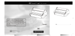
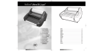
Instruction Manual Manuel d’utilisation Manual de instrucciones To Register this product go to www.gbc.com Pour enregistrer ce produit allez sur www.gbc.com Para registrar este producto entre en www.gbc.com English 4 Français 10 Español 16 1 2 3a 3b 4 5 6 7 8 TH RE AD IN G CA 9 10 RD Important Safety instructions YOUR SAFETY AS WELL AS THE SAFETY OF OTHERS IS IMPORTANT TO GBC. IN THIS INSTRUCTION MANUAL AND ON THE PRODUCT ARE IMPORTANT SAFETY MESSAGES. READ THESE MESSAGES CAREFULLY. Important Safeguards THE SAFETY ALERT SYMBOL PRECEDES EACH SAFETY MESSAGE IN THIS INSTRUCTION MANUAL. ON THE PRODUCT YOU WILL FIND IMPORTANT SAFETY MESSAGES. READ THESE MESSAGES AND INSTRUCTIONS CAREFULLY. SAVE THESE INSTRUCTIONS FOR LATER USE. THE FOLLOWING WARNINGS ARE FOUND ON THIS PRODUCT. Ꮨ WARNING Electrical shock hazard. Do not open. No user serviceable parts inside. Refer servicing to qualified service personnel. This safety message means that you could be seriously hurt or killed if you open the product and expose yourself to hazardous voltage. CAUTION HOT ROLLS. PINCH POINT. Keep hands and clothing away. This safety message means that you could be burned and your fingers and hands could be trapped and crushed in the hot rollers. Clothing, jewelry and long hair could be caught in the rollers and pull you into them. CAUTION SHARP BLADE. Keep hand and fingers away. WARNING: FOR YOUR PROTECTION, DO NOT CONNECT THE LAMINATOR TO ELECTRICAL POWER OR ATTEMPT TO OPERATE UNTIL YOU READ THESE INSTRUCTIONS COMPLETELY. KEEP OPERATING INSTRUCTIONS IN A CONVENIENT LOCATION FOR FUTURE REFERENCE. TO GUARD AGAINST INJURY, THE FOLLOWING BASIC SAFETY PRECAUTIONS MUST BE OBSERVED IN THE SET-UP AND USE OF THE LAMINATOR. General safeguards • Use this laminator only for its intended purposes as according to the specifications outlined in the operating instructions. • Keep hands, long hair, loose clothing and articles such as necklaces or ties away from the front of the pull rollers to avoid entanglement and entrapment. • Avoid contact with the heat shoes during operation or shortly after the laminator has been turned off. The heat shoes can reach temperatures in excess of 300ºF. • Keep hands and fingers away from the path of the sharp film cutter blade located at the film exit. • Do not place the laminator on an unstable cart, stand or table. An unstable surface may cause the laminator to fall resulting in serious bodily injury. Avoid quick stops, excessive force and uneven floor surfaces when moving the laminator on a cart or stand. • Do not defeat or remove electrical and mechanical safety equipment such as interlocks, shields and guards. • Do not insert objects unsuitable for lamination. • Do not expose laminator to liquids. Electrical safeguards • This laminator must be connected to a supply voltage corresponding to the electrical rating as indicated on the serial plate located on the rear of the machine. • Unplug the laminator before moving it, or when it is not in use for an extended period of time. This safety message means that you could cut yourself if you are not careful. 4 WARNING: THE SAFETY ALERT SYMBOL PRECEDES EACH SAFETY MESSAGE IN THIS INSTRUCTION MANUAL. THIS SYMBOL INDICATES A POTENTIAL PERSONAL SAFETY HAZARD THAT COULD HURT YOU OR OTHERS, AS WELL AS CAUSE PRODUCT DAMAGE OR PROPERTY DAMAGE. WARNING: DO NOT ATTEMPT TO SERVICE OR REPAIR THE LAMINATOR. WARNING: DO NOT CONNECT THE LAMINATOR TO AN ELECTRICAL SUPPLY OR ATTEMPT TO OPERATE THE LAMINATOR UNTIL YOU HAVE COMPLETELY READ THESE INSTRUCTIONS. MAINTAIN THESE INSTRUCTIONS IN A CONVENIENT LOCATION FOR FUTURE REFERENCE. • Do not operate the laminator with a damaged power supply cord or plug. • Do not overload electrical outlets as this can result in fire or shock. • Do not alter the attachment plug. This plug is configured for the appropriate electrical supply. • The unit is intended for indoor use only. CAUTION: The receptacle must be located near the equipment and easily accessible. Do not use an extension cord. • Disconnect the attachment plug from the receptacle to which it is connected and keep the power supply cord in your possession while moving the laminator. • Do not operate the laminator with a damaged power supply cord or attachment plug, upon occurrence of a malfunction, or after laminator has been damaged. Contact an authorized GBC service representative for assistance. Service Perform only the routine maintenance procedures referred to in these instructions. Do not attempt to service or repair the laminator. Unplug the unit and contact an authorized GBC service representative for any required repairs or one or more of the following has occurred: • The power supply cord or attachment plug is damaged. • Liquid has been spilled into the laminator. • The laminator is malfunctioning after being mishandled. • The laminator does not operate as described in these instructions. WARNING: THIS IS NOT A TOY - DO NOT ALLOW CHILDREN TO OPERATE THIS LAMINATOR! Installation • Shipping damage should be brought to the immediate attention of the delivering carrier. • Place the laminator on a stable flat surface capable of supporting 44lbs. The surface should be at least 30” high to assure comfortable positioning during operation. All four rubber feet should be on the supporting surface. • The laminator should be positioned to allow exiting film to drop freely to the floor. Accumulation of laminate as it exits the laminator may cause film to wrap around the rollers, causing a jammed condition. • Avoid placing laminator near sources of heat or cold. Avoid locating the laminator in the direct path of forced, heated or cooled air. • Connect power cord to an appropriate power source. Avoid connecting other equipment to the same branch circuit to which the laminator is connected as this may cause nuisance tripping of the circuit breaker or blown fuses. Caring for the Ultima 35 EZload The only maintenance required by the operator is to periodically clean the heat shoes. The following procedure will help keep the heat shoes free of adhesive that has been deposited along the edge of the laminating film. CAUTION: THE FOLLOWING PROCEDURE IS PERFORMED WHILE THE LAMINATOR IS HOT. USE EXTREME CAUTION. 1 Remove the film from the laminator following the procedure outlined in the section FILM LOADING AND THREADING. 2 Preheat the laminator until the READY LAMP ( 3 Clean the top and bottom heat shoes with a soft cloth. 4 Follow the procedure in section FILM LOADING AND THREADING, Method Using Film Threading Card to reload the laminator. ) illuminates. WARNING: Do not apply cleaning fluids or solvents to the rollers. NOTE: Do not use metal scouring pads to clean the heat shoes! WARNING: Do not attempt to laminate adhesives marked ‘Flammable’. WARNING: Do not laminate glitter and/or metallic items. Damage to the rollers may result. 5 Features Guide A. POWER SWITCH: Located at the back of the machine, applies power to the laminator. The ‘ON’ position is indicated by the ‘ ’ symbol. The ‘OFF’ position marked ‘ ’ symbol (figure 1). I. NIP ROLLERS: (figure 3b) The Nip Rollers are located behind the heat shoes. The nip point is where the heated film is compressed and pulled through the laminator. B. CONTROL PANEL: (figure 2) J. PULL ROLLERS: (figure 4) The Pull Rollers are located at the back of the laminator. They simultaneously pull the film through the laminator and provide tension as the film cools to provide good quality lamination. • POWER LAMP ( ): Indicates that the laminator is plugged in and the main power switch is in the ‘ON’ ( ) position. • READY LAMP ( ): This will illuminate when the laminator has reached operating temperature. • STANDBY SWITCH ( ): Push to turn laminator on or off when main power switch at the rear of machine is in the ‘ON’ ( ) position. • RUN / STOP / REVERSE SWITCH ( ): Controls the operation of the rollers. Select ‘RUN’ ( ) position to laminate. Select ‘STOP’ ( ) position when the laminated item has passed through the laminator. Select the ‘REVERSE’ ( ) position to clear mis-feed, jams or wrap-ups. • TEMPERATURE CONTROL KNOB ( ): Use to select appropriate laminating temperature. Refer to the laminating guide on the feed table to find the recommended setting. C. HEAT SHIELD: (figure 3a) Prevents inadvertent contact with the heat shoes. D. FEED TABLE: (figure 3a) The Feed Table is used to position items for lamination. The laminator will operate only when the Feed Table and Feed Table Latch are properly installed. E. FEED TABLE LATCH: (figure 3a) Used to lock the Feed Table into position and activate an interlock switch. The latch is located on the right underside of the Feed Table. The Feed Table can be removed by retracting the latch and lifting the table upward and away from the laminator. F. FEED TABLE GUIDE: (figure 3a) The Feed Table Guide aligns items to be laminated and is used to insure that longer items are fed into the laminator straight. The Feed Guide may also be used to feed smaller items side by side. Position the feed guide toward the centre of the Feed Table and place the items to be laminated against each side of the Feed Guide as they are being introduced into the laminator. To position the adjustable guide, lift the guide and slide it to the desired position. G. HEAT SHOES: (figure 3b) Teflon coated heat shoes melt the adhesive on the laminating film before the nip rollers compress it. H. IDLER BARS: (figure 3b) The Idler Bars, located near each supply roll, are used to direct the film to the heat shoes. The lower Idler Bar is attached to the Feed Table to facilitate easy film loading. 6 K. REAR SLITTER: (figure 4) Used to cut the film where it exits the rear of the laminator. L. FUSE: (figure 4) The Fuse is an electrical safety device, located under the main power switch. M. SUPPLY ROLL: (figure 5) The Film Supply Rolls have core plugs inserted into each end of the rolls. The left and right plugs are of a different color and diameter. The color and diameter of end plugs correspond to the size of the holder and color sticker located on the side plate of the laminator (figure 5, a & b). N. AUTO SHUT-OFF: After one hour of inactivity the laminator will shut down. To activate the laminator, with the main power switch in the ‘ON’ ( ) position, push the Standby Button ( ) on the control panel and wait for the ready light ( ) to illuminate. Film Loading and Threading Refer to Figure 6 and follow the procedures to remove the Feed Table and Heat Shield. 1 Remove the heat shield by sliding it to the left or right and lifting it up and away from the laminator. 2 Slide the feed table latch to the left. 3 Lift the feed table upwards and away from the laminator. CAUTION: HEAT SHOES COULD BURN YOU. A If reloading film, cut the remaining top and bottom film webs between the supply rolls and heat shoes. Be careful not to scratch the heat shoes. Remove the old rolls and check the heat shoes for adhesive residue. This can be easily removed by wiping with a damp cloth. Do not use abrasive, as they will damage the Teflon coating on the heat shoe. Change the top and bottom supply roll at the same time. 4 Raise the four film holder levers and remove old rolls of film (figure 7). 5 Install new film rolls making sure that color and diameter of end plugs correspond to the size of the holder and colour sticker located on the side plate of the laminator. 6 Close the four film holder levers. 7 Refer to Figure 8 or Threading Guide located on the feed table for illustration of properly loaded film. Unwind top and bottom film rolls allowing enough slack for threading. Drape the film from lower supply roll over the heat shoes allowing enough slack to re-install the feed table/idler bar. Thread film from upper roll under the idler bar and drape over heat shoes (Figure 9). 8 Re-install feed table and slide feed table latch to the right. 9 Re-install heat shield. B C 10 Move the RUN / STOP / REVERSE SWITCH ( ) to the ‘RUN’ ( ) position. Slide the threading card (provided with new rolls of GBC laminating film) on the feed table, gently pushing the film into the nip rollers (figure 10). The threading card should now be guiding both rolls of film through the laminator. 11 Move the RUN / STOP / REVERSE SWITCH ( ) to the ‘STOP’ ( ) position when the threading card exits the rear of the laminator. CAUTION: D SHARP BLADE. 12 The film cutter may be used to separate the laminated items. Position the cutter on either side of the laminator, depress the cutter handle while sliding the cutter across the film. E 7 Operation 1 2 3 Specifications CAUTION: MAKE SURE HEAT SHIELD AND FEED TABLE ARE IN THE PROPER POSITION TO OPERATE THE UNIT. Move the Main Power switch to the ‘ON’ ( ) position (figure 1). With the main power switch in the ‘ON’ ( ) position, the laminator can be turned on or off using the standby switch ( ) located on the control panel. When the standby switch is activated the red power indicator ( ) will illuminate. The laminator is now heating. Use the lamination guide on the feed table to select the correct laminating temperature for the film gauge and media that you are laminating. The guide will provide a good starting point. You may need to adjust the temperature up or down slightly to accommodate the finish or thickness of the media. When the laminator reaches operating temperature, the green ready indicator ( ) on the control panel will illuminate. 3 fpm Dimensions (W x L x H) 16.929 x 18.11 x 11.142 inch Weight 35lbs Voltage 120V ~ 60Hz / 230 ~ 50Hz Current A Power W BTU BTU/hour Warm-up Time 1 minute Electrical requirements - Refer to the serial plate located on the rear of the laminator for the specific electrical rating applicable to the unit. Lamination Guide 1.7mil 3mil 5mil 10mil 4 Position the item(s) to be laminated on the feed table. Copy Paper 5-7 5-7 5-8 5-7 5 Move the RUN / STOP / REVERSE SWITCH ( ( ) position. Glossy Paper 6-8 6-8 6-8 5-7 Photo Paper 6-9 7-9 7-9 5-7 ) to the ‘RUN’ 6 Slide the item(s) to be laminated into the nip rollers. 7 When the laminated item(s) exit(s the rear of the laminator, move the RUN / STOP / REVERSE SWITCH ( ) to the ‘STOP’ ( ) position. 8 Use the Rear Slitter located at the back of the laminator to separate the laminated item(s) from the film web. Clearing a Film Jam (Wrap-Up) Film jams may occur if the laminator is not positioned to allow exiting film to drop freely to the floor. Accumulation of laminate as it exits the laminator may cause film to wrap around the roller, causing a jammed condition. To clear a jam it is necessary to rotate the rollers in a reverse direction. To clear a jam: 8 Ultima35 EZLoad Operating Speed 1 Immediately stop the laminator by moving the RUN / STOP / REVERSE SWITCH ( ) to the ‘STOP’ ( ) position. 2 Remove the feed table and heat shield. 3 Cut the top and bottom film webs. 4 Grasp the loose ends of the web and pull straight out. Install the feed table with the loose ends of the web on top of the table. 5 Move the RUN / STOP / REVERSE SWITCH ( ) to the ‘REVERSE’ ( ) position and guide the film out of the laminator. 6 When the film has cleared the heat shoes, move the RUN / STOP / REVERSE SWITCH ( ) to the ‘STOP’ ( ) position. 7 Thread the film per section Film Loading and Threading. Material This chart is for reference only. Actual Temperature setting will vary depending on media thickness and ink coverage. Laminating Tips • Do not attempt to laminate abrasive or metal items such as staples or paper clips as they will damage the heat shoes and rollers. • Do not force items into the nip area of the rollers. An item that is not easily drawn into the laminator is probably too thick to laminate. • Wrinkles may result if an attempt is made to reposition an item once the rollers have grasped it. • Do not stop the laminator before an item has completely exited the rear of the laminator. Even a momentary stop will cause a mark (heat line) to appear on the laminated item. Adhesive will be deposited on the heat shoes and rollers if: • Only one roll of film is used. The top and bottom rolls must be used for problem free lamination. • One or both rolls of film are allowed to run completely off the core. Troubleshooting Guide SYMPTOM POSSIBLE CAUSE CORRECTIVE ACTION • POWER indicator does not illuminate when Main power switch is in the ‘ON’ ( ) position. Standby switch on control panel is not activated. Push standby switch on control panel. Laminator is not connected to electrical supply. Insert plug into appropriate receptacle. Fuse is blown. Replace fuse. • Laminated items are wrinkled. Tension on top or bottom supply roll is too loose. Film holder lever is not closed. Close lever completely. • Laminated items are wavy. Excessive heat. Reduce temperature by turning temperature control counter-clockwise. • Laminated items are cloudy. Insufficient heat. Increase temperature by turning temperature control clockwise. Ready light is not illuminated. Wait for the ready light to illuminate. Insufficient heat. Increase temperature by turning temperature control clockwise. • Unsatisfactory adhesion to media. Ready light must be illuminated. Laminated item may not be suitable for thermal lamination. The composition or finish of the media may not be compatible with the thermal lamination process. Warranty Operation of this machine is guaranteed for two years from date of purchase, subject to normal use. Within the guarantee period, GBC will at its own discretion either repair or replace the defective machine free of charge. Defects due to misuse or use for inappropriate purposes are not covered under the guarantee. Proof of date of purchase will be required. Repairs or alterations made by persons not authorized by GBC will invalidate the guarantee. It is our aim to ensure that our products perform to the specifications stated. This guarantee does not affect the legal rights which consumers have under applicable national legislation governing the sale of goods. Register this product online at www.gbc.com 9 General Binding Corp. Northbrook, Illinois 60062, USA www.gbc.com