1
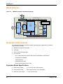
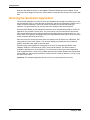
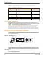
Stellaris® LM3S811 Evaluation Board U S E R ’S M A N U A L EK-LM3S811 -02 Co pyrigh t © 200 6-200 8 Lumin ary Micro, In c. Legal Disclaimers and Trademark Information INFORMATION IN THIS DOCUMENT IS PROVIDED IN CONNECTION WITH LUMINARY MICRO PRODUCTS. NO LICENSE, EXPRESS OR IMPLIED, BY ESTOPPEL OR OTHERWISE, TO ANY INTELLECTUAL PROPERTY RIGHTS IS GRANTED BY THIS DOCUMENT. EXCEPT AS PROVIDED IN LUMINARY MICRO’S TERMS AND CONDITIONS OF SALE FOR SUCH PRODUCTS, LUMINARY MICRO ASSUMES NO LIABILITY WHATSOEVER, AND LUMINARY MICRO DISCLAIMS ANY EXPRESS OR IMPLIED WARRANTY, RELATING TO SALE AND/OR USE OF LUMINARY MICRO’S PRODUCTS INCLUDING LIABILITY OR WARRANTIES RELATING TO FITNESS FOR A PARTICULAR PURPOSE, MERCHANTABILITY, OR INFRINGEMENT OF ANY PATENT, COPYRIGHT OR OTHER INTELLECTUAL PROPERTY RIGHT. LUMINARY MICRO’S PRODUCTS ARE NOT INTENDED FOR USE IN MEDICAL, LIFE SAVING, OR LIFE-SUSTAINING APPLICATIONS. Luminary Micro may make changes to specifications and product descriptions at any time, without notice. Contact your local Luminary Micro sales office or your distributor to obtain the latest specifications before placing your product order. Designers must not rely on the absence or characteristics of any features or instructions marked "reserved" or "undefined." Luminary Micro reserves these for future definition and shall have no responsibility whatsoever for conflicts or incompatibilities arising from future changes to them. Copyright © 2006–2008 Luminary Micro, Inc. All rights reserved. Stellaris, Luminary Micro, and the Luminary Micro logo are registered trademarks of Luminary Micro, Inc. or its subsidiaries in the United States and other countries. ARM and Thumb are registered trademarks, and Cortex is a trademark of ARM Limited. Other names and brands may be claimed as the property of others. Luminary Micro, Inc. 108 Wild Basin, Suite 350 Austin, TX 78746 Main: +1-512-279-8800 Fax: +1-512-279-8879 http://www.luminarymicro.com 2 January 6, 2009 Stellaris® LM3S811 Evaluation Board Revision History This table provides a summary of the document revisions. Date Revision September 2006 00 Initial release of doc to customers. December 2006 01 Changed value in Table B-1 for Pad 11. January 2009 02 Changed value in Table 3-1 for User Push Switch Input. January 6, 2009 Description 3 4 January 6, 2009 Stellaris® LM3S811 Evaluation Board Table of Contents Chapter 1: Stellaris® LM3S811 Evaluation Board ......................................................................................... 9 Features.............................................................................................................................................................. 9 Block Diagram .................................................................................................................................................. 10 Evaluation Kit Contents .................................................................................................................................... 10 Evaluation Board Specifications ................................................................................................................... 10 System Requirements................................................................................................................................... 11 Supported Devices........................................................................................................................................ 11 Features of the LM3S811 Microcontroller......................................................................................................... 11 Chapter 2: Getting Started ............................................................................................................................. 13 Powering the Board .......................................................................................................................................... 13 Installing the Drivers ......................................................................................................................................... 13 Driver Installation .......................................................................................................................................... 13 Completing Driver Installation ....................................................................................................................... 13 Running the Quickstart Application................................................................................................................... 14 Chapter 3: Hardware Description .................................................................................................................. 15 LM3S811 Microcontroller.................................................................................................................................. 15 Device Overview ........................................................................................................................................... 15 Clocking ........................................................................................................................................................ 15 Reset............................................................................................................................................................. 15 Power Supply................................................................................................................................................ 15 Debugging..................................................................................................................................................... 15 USB Device Controller Functions ..................................................................................................................... 16 Device Overview ........................................................................................................................................... 16 USB to JTAG/SWD ....................................................................................................................................... 16 Virtual COM Port........................................................................................................................................... 16 Organic LED Display ........................................................................................................................................ 16 Features........................................................................................................................................................ 16 Control Interface ........................................................................................................................................... 16 Power Supply................................................................................................................................................ 17 Design Guidelines......................................................................................................................................... 17 Further Reference......................................................................................................................................... 17 Other Peripherals.............................................................................................................................................. 17 Thumbwheel Potentiometer .......................................................................................................................... 17 User LED ...................................................................................................................................................... 17 User Pushbutton ........................................................................................................................................... 17 Bypassing Peripherals ...................................................................................................................................... 17 Interfacing to the EVB....................................................................................................................................... 18 Using the In-Circuit Debugger Interface ........................................................................................................... 18 ICDI Features................................................................................................................................................ 18 Enabling ICDI Mode...................................................................................................................................... 19 ARM Target Cable ........................................................................................................................................ 19 Starting ICDI ................................................................................................................................................. 19 January 6, 2009 5 Chapter 4: Communications .......................................................................................................................... 21 Using the Virtual COM Port .............................................................................................................................. 21 Confirming Driver Installation........................................................................................................................ 21 Installing the VCP Device Driver................................................................................................................... 22 About HyperTerminal........................................................................................................................................ 24 Starting HyperTerminal ................................................................................................................................. 24 Appendix A: Schematics................................................................................................................................ 27 Appendix B: Connection Details ................................................................................................................... 31 Component Locations....................................................................................................................................... 31 Evaluation Board Dimensions........................................................................................................................... 31 I/O Breakout Pads and Recommended Connectors......................................................................................... 32 ARM Target Pinout ........................................................................................................................................... 33 Appendix C: Contact Information ................................................................................................................. 35 6 January 6, 2009 Stellaris® LM3S811 Evaluation Board List of Figures Figure 1-1. Figure 1-2. Figure 3-1. Figure 4-1. Figure A-1. Figure A-2. Figure B-1. Figure B-2. Evaluation Board Layout ................................................................................................................. 9 LM3S811 Evaluation Board Block Diagram .................................................................................. 10 ICD Interface Mode ....................................................................................................................... 18 Check VCP Driver Installation ....................................................................................................... 21 LM3S811 Microcontroller (sheet 1 of 2) ........................................................................................ 28 LM3S811 Microcontroller (sheet 2 of 2) ........................................................................................ 29 Component Locations ................................................................................................................... 31 Evaluation Board Dimensions ....................................................................................................... 31 January 6, 2009 7 Stellaris® LM3S811 Evaluation Board List of Tables Table 3-1. Table B-1. Table B-2. Table B-3. Isolating On-Board Hardware........................................................................................................ 18 I/O Breakout Pads ......................................................................................................................... 32 Recommended Connectors........................................................................................................... 32 20-Pin JTAG/SWD Configuration .................................................................................................. 33 January 6, 2009 8 C H A P T E R 1 Stellaris® LM3S811 Evaluation Board The Stellaris® LM3S811 Evaluation Board is both a compact and versatile evaluation platform for the Stellaris LM3S811 ARM® Cortex™-M3-based microcontroller, and an In-Circuit Debug Interface (ICDI) for any Stellaris microcontroller-based target board. The EVB allows users to evaluate, prototype, and create application-specific designs. Features The Stellaris® LM3S811 Evaluation Board includes the following features: Stellaris® LM3S811 microcontroller OLED graphics display with 96 x 16 pixel resolution User-programmable pushbutton and LED Reset pushbutton and power indicator LED Thumbwheel potentiometer for driving an Analog-to-Digital Converter (ADC) input Standard ARM® 20-pin JTAG debug connector for use as an In-Circuit Debug Interface (ICDI) I/O signal break-out pads for hardware prototyping UART0 accessible through a USB Virtual COM Port (VCP) USB interface for all communication and power Evaluation copy of the Keil™ RealView® Microcontroller Development Kit software tools Figure 1-1 shows the layout of the Stellaris® LM3S811 Evaluation Board. Figure 1-1. Evaluation Board Layout Thumbwheel Potentiometer Reset Switch StellarisTM LM3S811 OLED Display USB Interface User LED User Push Switch January 6, 2009 JTAG/SWD to external target 9 Block Diagram Block Diagram LM3S811 Evaluation Board Block Diagram Target Cable Figure 1-2. Dual USB Device Controller Stellaris LM3S811 MCU I/O Signals USB Cable USB OLED Display 96 x 16 SWD/JTAG Mux 20-pin ARM JTAG/SWD Output Debug I/O Signal Break-out UART0 Switch Pot Reset +5V +3.3V Voltage Regulator Reset LED I/O Signal Break-out Evaluation Kit Contents The evaluation kit contains everything needed to develop and run applications for Stellaris microcontrollers including: LM3S811 Evaluation Board (EVB) USB cable 20-pin JTAG/SWD target cable CD containing: – Keil™ RealView® Microcontroller Development Kit RVMDK (16 KB limited) – Complete documentation – Quickstart guide – Quickstart source code – DriverLib and example source code Evaluation Board Specifications 10 Board supply voltage: 4.37–5.25 Vdc from USB connector Board supply current: 80 mA typ (fully active, CPU at 50 MHz) Break-out power output: 3.3 Vdc (100 mA max) January 6, 2009 Stellaris® LM3S811 Evaluation Board Dimensions: 3.65” x 1.40” x 0.30” (LxWxH) RoHS status: Compliant System Requirements Microsoft Windows 2000, XP, or 2003 128 MB of RAM (512 MB recommended) 100 MB of available hard-disk space 1024 x 768 minimum screen resolution CD-ROM drive USB port Supported Devices In-Circuit Debug Interface (ICDI) mode presently supports all Luminary Micro Stellaris Family devices. Features of the LM3S811 Microcontroller 32-bit ARM® Cortex™-M3 v7M architecture optimized for small-footprint embedded applications – Thumb®-compatible Thumb-2-only instruction set processor core for high code density – 50-MHz operation – Hardware-division and single-cycle-multiplication – Integrated Nested Vectored Interrupt Controller (NVIC) providing deterministic interrupt handling – 27 interrupt channels with eight priority levels 64 KB single-cycle flash with two forms of flash protection on a 2-KB block basis 8 KB single-cycle SRAM Three timers, each of which can be configured: as a single 32-bit timer, as a dual 16-bit timer with capture and simple PWM modes, or to initiate an ADC event Real-Time Clock (RTC) capability Separate watchdog clock with an enable Programmable interrupt generation logic with interrupt masking Lock register protection from runaway software Reset generation logic with an enable/disable Synchronous Serial Interface (SSI) Programmable interface operation for Freescale SPI, National Semiconductor MICROWIRE™, or Texas Instruments synchronous serial – Master or slave operation Two fully programmable 16C550-type UARTs – Separate 16x8 transmit (TX) and 16x12 receive (RX) FIFOs to reduce CPU interrupt service loading January 6, 2009 11 Features of the LM3S811 Microcontroller – Programmable baud-rate generator Analog-to-Digital Converter (ADC) – Single- and differential-input configurations – Four 10-bit channels (inputs) when used as single ended inputs – Sample rate of 500 thousand samples/second 12 I2C Bus with Master and slave receive and transmit operation with transmission speed up to 100 Kbps in Standard mode and 400 Kbps in Fast mode Six motion-control PWM outputs 1 to 32 GPIOs, depending on user configuration On-chip Linear Drop-Out (LDO) voltage regulator 3.3-V supply brownout detection and reporting via interrupt or reset On-chip temperature sensor 48-pin RoHS-compliant LQFP Industrial operating temperature January 6, 2009 C H A P T E R 2 Getting Started The Stellaris LM3S811 Evaluation Kit EKK-LM3S811 Quickstart provides step-by-step instructions for getting started with your Stellaris LM3S811 Evaluation Kit. For your convenience these instructions are summarized below. Powering the Board The Stellaris LM3S811 Evaluation Board (EVB) is configured for immediate use. To power the EVB, use the USB cable supplied in the kit. Connect the mini-b (smaller) end of the USB cable to the connector labeled “USB” on the EVB. Connect the other end (Type A) to a free USB port on your host PC. The USB interface is capable of sourcing up to 500 mA for each attached device, which is sufficient for the evaluation board. If connecting the board through a USB hub, it must be a powered hub. When you plug in the EVB for the first time, Windows starts the Found New Hardware Wizard. The Stellaris LM3S811 Evaluation Kit Quickstart Guide steps through the process of installing drivers for the Stellaris LM3S811 Evaluation Board. Installing the Drivers The Stellaris LM3S811 Evaluation Board requires several hardware drivers. All drivers are located in the \Tools\Ftdi directory on the Software and Documentation CD. Each time Windows requests a driver for this device, point it to the Software and Documentation CD. Driver Installation When the Found New Hardware Wizard starts, Windows asks if it can connect to Windows Update to search for software. Select “No, not this time,” and then click Next. The Found New Hardware Wizard then asks you from where to install the software. Select “Install from a list or specific location (Advanced)” and click Next. Make sure the Documentation and Software CD that came with the evaluation kit is in your CD-ROM drive. Select “Search for the best driver in these locations,” and check the “Search removable media (floppy, CD-ROM…)” option. Click Next. A warning pops up during the Hardware Installation; click Continue Anyway. Windows now finishes installing the drivers for “LM3S811 Evaluation Board A.” When the driver install is finished, a window appears. Click Finish to close the dialog box. Completing Driver Installation You have just installed the drivers for “LM3S811 Evaluation Board A”. The USB device built into the EVB is a composite USB device. After you click Finish, a new Found New Hardware Wizard window appears asking to install drivers for another device. This is for the “LM3S811 Evaluation Board B” part of the composite USB device. Follow the same instructions as above to install the drivers for this device. The Found New Hardware Wizard appears one last time. This is to install the drivers for the “LM3S811 Virtual COM Port”. Again, follow the same instructions above to install the drivers for this device. January 6, 2009 13 Getting Started Now all of the hardware drivers for the LM3S811 Evaluation Board have been installed. These drivers give the debugger access to the JTAG interface and the host PC access to the Virtual COM Port. Running the Quickstart Application The quickstart application is a game in which you navigate a ship through an endless tunnel. Use the potentiometer (POT) to move the ship up and down, and the user pushbutton (USER) to fire a missile to destroy obstacles in the tunnel. Score accumulates for survival and destroying obstacles. The game lasts for only one ship; the score displays at the end of the game. Since the OLED display on the evaluation board has burn-in characteristics similar to a CRT, the application also contains a screen saver. The screen saver only becomes active if two minutes have passed without the user pushbutton being pressed while waiting to start the game (i.e., the screen saver never appears during game play). An implementation of the Game of Life is run with a field of random data as the seed value. After two minutes of running the screen saver, the display turns off and the user LED blinks. Exit either mode of screen saver (Game of Life or blank display) by pressing the user pushbutton (USER). Press the button again to start the game. While the game is being played, a running tally of the score is output through UART0 of the LM3S811. UART0 is connected to the FTDI’s second serial channel. This serial channel is available to Windows as a Virtual COM Port. To view the score, open up a terminal application such as HyperTerminal. Connect using COM#, where # is the number Windows has assigned the Virtual COM Port. Set the serial connection to a baud rate of 115200, 8 data bits, no parity, 1 stop bit, and no flow control. Important: The quickstart application will not run if one or more jumpers are removed. 14 January 6, 2009 C H A P T E R 3 Hardware Description This chapter provides the hardware description for the LM3S811 microcontroller including the peripherals included in the evaluation kit. LM3S811 Microcontroller Device Overview The heart of the EVB is a Stellaris LM3S811 ARM® Cortex™-M3-based microcontroller. The LM3S811 offers 64 KB flash memory, 50-MHz operation, a 4-channel ADC, and a wide range of peripherals. Refer to the LM3S811 data sheet (order number DS-LM3S811) for complete device details. The LM3S811 microcontroller is factory programmed with a quickstart demo program. The quickstart program resides in the LM3S811 on-chip flash memory and runs each time power is applied, unless ICDI mode is in use, or the quickstart has been replaced with a user program. Clocking A single external 6.0-Mhz crystal drives the LM3S811 microcontroller. All required internal clocks are generated automatically within the device. The LM3S811 microcontroller is designed to run the ARM Cortex core at 50 Mhz on this evaluation board. Reset The LM3S811 microcontroller shares its external reset input with the OLED display. Reset is asserted (Active Low) under any one of the following conditions: Power-on reset (duration set by resistor R1 and capacitor C17) Reset switch SW2 is held down In ICDI mode By the USB device controller (U2 FT2232), when instructed by the debugger The Keil RVMDK debugger does not support external reset. Instead, the target device is reset using JTAG operations. In ICDI mode, the reset push-switch has no effect. Power Supply The LM3S811 is powered from a +3.3-V supply rail that is common to all devices on the EVB. A low-dropout (LDO) regulator regulates +5 V power from the USB cable to +3.3 V. +3.3 V at up to 100 mA is available for powering external circuits at break-out pin 20. Debugging Stellaris microcontrollers support programming and debugging using either JTAG or SWD. JTAG uses the TCK, TMS, TDI, and TDO signals. SWD requires fewer signals—SWCLK, SWDIO, and SWO. The debugger determines which debug protocol is used. For example, Keil RVMDK tools support only JTAG debugging. January 6, 2009 15 Hardware Description JTAG/SWD signals are multiplexed with GPIO functions inside the Stellaris microcontroller. Do not configure JTAG/SWD pins (including PB7/TRST) as GPIO. Doing this prevents in-circuit programming and debugging. USB Device Controller Functions Device Overview An FT2232 device from Future Technology Devices International Ltd manages USB-to-serial conversion. The FT2232 is factory configured by Luminary Micro to implement a JTAG/SWD port (synchronous serial) on channel A and a Virtual COM Port (VCP) on channel B. This feature allows two simultaneous communications links between the host computer and the target device using a single USB cable. Separate Windows drivers for each function are provided on the Documentation and Software CD. A small serial EEPROM holds the FT2232 configuration data. The EEPROM is not accessible by the LM3S811 microcontroller. For full details on FT2232 operation, go to www.ftdichip.com. USB to JTAG/SWD The FT2232 USB device performs JTAG/SWD serial operations under the control of the debugger. Two 74LV125 hex buffers multiplex SWD and JTAG functions and provide direction control for the bi-directional data line when working in SWD mode. Virtual COM Port The Virtual COM Port (VCP) allows Windows applications (such as HyperTerminal) to communicate with UART0 on the LM3S811 over USB. Once the FT2232 VCP driver is installed, Windows assigns a COM port number to the VCP channel. For more information, see Using the Virtual COM Port on page 21. Organic LED Display The EVB features an Organic LED (OLED) graphics display with 96 x 16 pixel resolution. OLED is a new technology that offers many advantages over LCD display technology. Features Osram OS096016 series display 96 columns by 16 rows 1 bit/pixel monochrome High-contrast (typ. 2000:1) Excellent brightness (120 cd/m2) Fast response Control Interface The OLED display has a built-in controller IC (SSD0303) with synchronous serial and I2C interfaces. I2C is used on the EVB as it only requires two microcontroller pins. The OLED display has a fixed I2C address of 0x3d. The Stellaris driver library (DriverLib) (included on the 16 January 6, 2009 Stellaris® LM3S811 Evaluation Board Documentation and Software CD) contains complete drivers with source-code for the OLED display. Note that the SSD0303’s I2C bus implementation is not 100% compliant with the I2C specification. Designers should refer to the SSD0303 datasheet before connecting other I2C devices to the bus. Power Supply A +9 V supply is needed to bias the OLED display. Conveniently, the SSD0303 IC includes an on-chip voltage boost controller. A few external components complete the simple switching power supply. This supply is dedicated to the OLED display and should not be used to power other devices. Design Guidelines The OLED display has a lifetime of about 10,000 hours. It is also prone to degradation due to burnin, similar to CRT and plasma displays. The quickstart application includes both a screen-saver and a power-down mode to extend display life. These factors should be considered when developing EVB applications that use the OLED display. When using the EVB as an In-Circuit Debug Interface (ICDI), the OLED display is held in reset to reduce power consumption and eliminate display wear-out. Further Reference For additional information on the OS096016 OLED display, visit www.osram-os.com. Full details on the SSD0303 controller are available from Solomon Systech, Ltd. (www.solomon-systech.com). Other Peripherals Thumbwheel Potentiometer A thumbwheel potentiometer connects to Channel 0 of the Analog-to-Digital Converter (ADC). A padding resistor (R31) sets the voltage range to 0 to 3.0 V. This corresponds with the full-scale range of the LM3S811’s 10-bit ADC. The ADC input voltage increases with clockwise potentiometer rotation. User LED A user LED (D2) is provided for general use. The LED is connected to PC5/CCP1, allowing the option of either GPIO or PWM control (brightness control). Refer to the Quickstart Application source code for an example of PWM control. User Pushbutton A user pushbutton (SW1) is provided for general use. The switch interfaces to PC4 of the LM3S811. Bypassing Peripherals The EVB’s on-board peripheral circuits require seven GPIO lines, leaving up to 25 GPIO lines immediately available for connection to external circuits. If all GPIO lines are needed, then the on-board hardware can be bypassed. The EVB is populated with seven 0-ohm resistor jumpers, which can be removed to isolate on-board hardware. January 6, 2009 17 Hardware Description Important: The quickstart application will not run if one or more jumpers are removed. Table 3-1. Isolating On-Board Hardware MCU Pin EVB Function To Isolate, Remove... Pin 33 PB2/I2CSCL I2C SCL to Display JP1 Pin 34 PB3/I2CSDA I2C SDA to Display JP2 Pin 17 PA0/U0Rx VCP Receive JP3 Pin 18 PA1/U0Tx VCP Transmit JP4 Pin 1 ADC0 ADC Input from Thumbwheel Potentiometer JP5 Pin 14 GPIO PC4 User Push Switch Input JP6 Pin 29 GPIO PC4 User LED output JP7 Interfacing to the EVB An array of accessible I/O signals makes it easy to interface the EVB to external circuits. All LM3S811 I/O lines (except those with JTAG functions) are brought out to 0.1” pitch pads. For quick reference, silk-screened labels on the PCB show primary pin functions. Table B-1 on page 32 has a complete list of I/O signals as well as recommended connectors. Most LM3S811 I/O signals are +5-V tolerant. 5-V tolerant pins will not be damaged when connected to 5-V logic circuits. It is recommended that datasheets be checked for compatibility when mixing logic types. Refer to the LM3S811 datasheet for detailed electrical specifications. Using the In-Circuit Debugger Interface The Stellaris LM3S811 Evaluation Kit can operate as an In-Circuit Debugger Interface (ICDI). ICDI acts as a USB to the JTAG/SWD adaptor, allowing debugging of any external target board that uses a Stellaris microcontroller. Figure 3-1. ICD Interface Mode LM3S811 EVB ` USB Stellar is MC U PC with IDE/ debugger J TAG/SWD Targ et C abl e Stellaris MC U Target Board This LM 3 S811 is he ld in re set The debug interface operates in either Serial-Wire Debug (SWD) or full JTAG mode, depending on the configuration in the debugger IDE. The Keil RVMDK does not distinguish between normal Evaluation Board mode and ICDI mode. The only requirement is that the correct Stellaris device is selected in the project configuration. ICDI Features ICDI includes the following features: 18 January 6, 2009 Stellaris® LM3S811 Evaluation Board Standard ARM® 20-pin JTAG debug connector USB 2.0 full speed interface allows JTAG/SWD debug Compatible with leading ARM Integrated Development Environment (IDE) packages including Keil RVMDK. Enabling ICDI Mode ICDI mode is enabled when the 20-pin JTAG/SWD target cable is connected to an external target. In this mode, the on-EVB LM3S811 microcontroller and OLED display are held in reset. Applications can not be executed in the on-EVB microcontroller when the EVB is connected as an ICDI device. ARM Target Cable The evaluation kit includes a 3-inch target cable for connecting the EVB to an external target. Cables up to 8-inch long can be used if required. Target cable pin assignments are compatible with the ARM 20-pin standard (see Table B-3 on page 33). The target board must have GND connections on even pins from 4 through 20, otherwise the ICDI is not enabled when the target is connected. In this case, there will be conflict between the JTAG/SWD signals on the LM3S811evaluation board and the external Stellaris device. When using the kit as an evaluation board, do not make connections to the debug out connector. Starting ICDI With the USB cable removed, connect the EVB to a Stellaris microcontroller-based target board using the 20-pin JTAG/SWD target cable included in the Stellaris LM3S811 Evaluation Kit. The red stripe on the cable should match pin 1 on both the EVB debug out connector and the target. When inserted correctly, the polarizing tab on the connector fits into the slot on the EVB PCB, so that the ribbon cable exits away from you. Apply power to the target device, and then connect the USB cable to the LM3S811 Evaluation Board. The OLED display should not show any information. If it does display an image, then check the target JTAG/SWD connections to ensure the on-EVB LM3S811 microcontroller is being held in reset. The Keil RVMDK is now be able to program and debug the target Stellaris microcontroller. January 6, 2009 19 Hardware Description 20 January 6, 2009 C H A P T E R 4 Communications This chapter describes available communication for the LM3S811 microcontroller through the Virtual COM Port and the Windows application, HyperTerminal. Using the Virtual COM Port The Virtual COM Port (VCP) is a convenient way for Windows applications to communicate with UART0 on the LM3S811 microcontroller over USB. It offers all the capabilities of a standard RS232 interface without an additional cable. Confirming Driver Installation The VCP device driver is normally installed as part of the quickstart process. Confirm that the VCP device driver is installed by doing the following. 1. Connect the EVB to a PC using the USB cable supplied in the evaluation kit. 2. Open the Windows Device Manager, by either holding down the Windows Key and pressing the Pause/Break key, or, from the Start Menu, selecting Control Panel and then clicking on the System Icon. 3. Select the Hardware Tab, and click the Device Manager button. 4. In Device Manager, scroll down until you see Ports (COM & LPT). Click to expand this item. You should see a device called LM3S811 Virtual COM Port (COM). Figure 4-1. Check VCP Driver Installation VCP Driver Installed VCP Device Missing The Windows operating system assigns the COM Port number automatically. It may change if the EVB is reconnected. If Device Manager does not show the LM3S811 Virtual COM Port device, or if there is a question mark by the device, it will be necessary to install or reinstall the device driver. January 6, 2009 21 Communications Installing the VCP Device Driver When the EVB is first connected to a USB port, Windows automatically starts a driver installation wizard. The following steps guide you through the installation wizard. 1. Connect the EVB to an available USB port using the USB cable supplied in the kit. In the Found New Hardware Wizard window, select “No, not this time” and click Next. 2. Select “Install from a list or specific location (Advanced)” and click Next. 22 January 6, 2009 Stellaris® LM3S811 Evaluation Board 3. Insert the Stellaris® LM3S811 Evaluation Kit Documentation and Software CD in the CD-ROM drive. Select “Search removable media (floppy, DR-ROM…)” and click Next. 4. Windows locates the driver on the Documentation and Software CD and start installing the driver. A warning dialog like the one below pops up. Click Continue Anyway. January 6, 2009 23 Communications 5. VCP drivers are now installed. Click Finish. You may want to use Device Manager to identify the COM Port assignment. Now that drivers are installed, Windows automatically assign a COM port to the LM3S811 Evaluation Board each time it is connected. About HyperTerminal HyperTerminal is an ASCII terminal emulator that is included with Windows. It provides an easy way to transfer ASCII data to and from the LM3S811 Evaluation Board using the Virtual COM port feature. The quickstart application sends a running tally of the game score through UART0 of the LM3S811. Starting HyperTerminal 1. From the Windows XP Start menu, select: Start > All Programs > Accessories > Communications > HyperTerminal 2. HyperTerminal asks for a name and icon to associate with the terminal profile you are about to create. Neither the name nor the icon selection is critical. 24 January 6, 2009 Stellaris® LM3S811 Evaluation Board 3. Click OK to continue. 4. Select the COM port assigned to the LM3S811 Evaluation Board. In the example below, it is COM7. Click OK. January 6, 2009 25 Communications 5. Use the Properties dialog box to set the Port Settings. The quickstart application sends data at 115200 baud, 8 data bits, no parity, 1 stop bit, and no flow-control. Click OK. 6. HyperTerminal now starts. When the quickstart game is played, score data is visible in the terminal window. Save the terminal settings when exiting HyperTerminal. 26 January 6, 2009 A P P E N D I X A Schematics Schematics for the Stellaris LM3S811 Evaluation Board follow. January 6, 2009 27 28 D C B A Aug 30, 06 A2 1 Aug 21, 06 A1 18PF C9 LM3S811 GND GND GND GND RST OSC0 OSC1 ADC0 ADC1 ADC2 ADC3 PE0/PWM4 PE1/PWM5 PC0/TCK/SWCLK PC1/TMS/SWDIO PC2/TDI PC3/TDO/SWO PC4 PC5/CCP1 PC6/CCP3 PC7/CCP4 PA0/U0Rx PA1/U0Tx PA2/SSIClk PA3/SSIFss PA4/SSIRx PA5/SSITx U1 6MHZ_CLOCK 8 16 24 31 5 9 10 OSC0 RESETn 1 2 3 4 PE0/PWM4 PE1/PWM5 ADC0 ADC1 ADC2 ADC3 35 36 PC4 PC5/CCP1 PC6/CCP3 PC7/CCP4 17 18 19 20 21 22 40 39 38 37 14 13 12 11 PA0/U0Rx PA1/U0Tx PA2/SSIClk PA3/SSIFss PA4/SSIRx PA5/SSITx 2 Add C17 (0.1uF) to reset circuit. 2 D5,D6 function redundant - change to resistors. Change R2 to 10 ohms. Release for Rev A PCB Release for Rev 0 PCB Aug 2, 06 Aug 18, 06 Description 18PF 0.1UF Date C8 0 2 6.00MHz 1 Y1 TCK/SWCLK TMS/SWDIO TDI TDO C17 10 R33 10 R32 SW2 SW-PB R1 10K +3.3V A Revision History EXTDBGENn USB_RSTn Eval Reset Switch 1 7 15 23 32 6 25 26 27 28 45 46 47 48 3 0.1UF C11 40 39 38 37 36 35 34 33 32 31 30 29 28 27 26 25 24 23 22 21 LDO 0.1UF C14 ADC3 ADC2 ADC1 ADC0 GND PD4/CCP0 PC5/CCP1 PD5/CCP2 PC6/CCP3 GND PD7/C0O PB4/C0PB6/C0+ PB7 PE0/PWM4 PE1/PWM5 PB3/I2CSDA PB2/I2CSCL RESETn GND 0.1UF C13 +3.3V PB7 0.1UF C12 R30 10K +3.3V I/O Breakout Headers 1 2 3 4 5 6 7 8 9 10 11 12 13 14 15 16 17 18 19 20 0.1UF C10 PD0/PWM0 PD1/PWM1 PD2/U1Rx PD3/U1Tx PD4/CCP0 PD5/CCP2 PD6/Fault PD7/C0O PB0/PWM2 PB1/PWM3 PB2/I2CSCL PB3/I2CSDA PB4/C0PB5/CCP5 PB6/C0+ Pin 1 is Omitted for Polarization PC7/CCP4 PB5/CCP5 PD6/Fault PC4 PA0/U0Rx PA1/U0Tx PA2/SSIClk PA3/SSIFss PA4/SSIRx PA5/SSITx PD1/PWM1 PD0/PWM0 GND PD2/U1Rx PD3/U1Tx PB0/PWM2 PB1/PWM3 GND +3.3V VDD VDD VDD VDD LDO PD0/PWM0 PD1/PWM1 PD2/U1Rx PD3/U1Tx PD4/CCP0 PD5/CCP2 PD6/Fault PD7 PB0/PWM2 PB1/PWM3 PB2/I2CSCL PB3/I2CSDA PB4/C0PB5/CCP5 PB6/C0+ PB7/TRST 29 30 33 34 44 43 42 41 3 4 1UF C15 +9V 4 R4 1.5K R3 10K 1UF 1UF PC5/CCP1 PC4 ADC0 PA1/U0Tx PA0/U0Rx PB3/I2CSDA PB2/I2CSCL C5 C4 CD0603-S0180 D3 JP7 JP6 JP5 JP4 JP3 JP2 JP1 Q1 BSS123 LEDPWRIN R2 10 C3 1UF R6 2.2K 220 5 R10 VCP_RX VCP_TX R5 2.2K +3.3V +3.3V 100uH L1 OLED Voltage Boost Circuit 5 D2 Green SW1 SW-PB R9 10K +3.3V GND R8 50K R31 4.7K +3.3V GND +3.3V 1UF C6 GND 1UF C7 RESETn 1 2 3 4 5 6 7 8 9 10 11 12 13 14 15 16 17 18 19 20 21 22 23 24 25 26 27 28 29 30 31 Date: 9/3/2006 1 6 Sheet 1 of 2 Rev A2 MCU, Peripherals and I/O Breakout Document Number: Page Title: B LM3S811 Evaluation Board Size B A D Remove JP1..7 (0603 Resistors) to C free GPIO lines as required. Peripheral Devices Drawing Title: Status LED User Push Button 96x16 OLED DISPLAY OSRAM OS096016PP08MG1B10 OS096016PP08MO1B10 OS096016PP08MY0B10 NC VSS GDR VDDB FB RESE VBREF NC NC NC VDD BS1 BS2 NC CSn RESn D/Cn R/Wn E/RDn D0 D1 D2 D3 D4 D5 D6 D7 IREF VCOMH VCC N.C. U2 Thumbwheel Potentiometer GND 620K R7 GND +3.3V 1UF C1 +3.3V GND 6 Figure A-1. LM3S811 Microcontroller (sheet 1 of 2) January 6, 2009 D C B +5V D- 2 5V 1 CS SK DI DO 1K 64X16 CAT93C46 VCC NC ORG GND U6 1 1 2 3 4 74LVC126APWR 2.2K R18 7 47PF C30 Locate U3A close to U1 Oscillator 2 +3.3V 1 U3A R17 10K 3 D+ 3 +5V G ID 4 60ohm @ 100 MHz FB1 6 6MHZ_CLOCK 8 7 6 5 +5V P2 5 USB MINI-B Receptacle R21 10K +5V R12 27 R11 27 10K R20 2 +5V 1UF C26 R15 1.5K 0.1UF C16 45 9 18 25 34 4 5 43 44 48 1 2 47 7 8 6 AVCC VCC VCC VCCIOA VCCIOB PWREN# BCBUS0 BCBUS1 BCBUS2 BCBUS3 SI/WUB BDBUS0 BDBUS1 BDBUS2 BDBUS3 BDBUS4 BDBUS5 BDBUS6 BDBUS7 ACBUS0 ACBUS1 ACBUS2 ACBUS3 SI/WUA ADBUS0 ADBUS1 ADBUS2 ADBUS3 ADBUS4 ADBUS5 ADBUS6 ADBUS7 46 3 42 14 31 41 30 29 28 27 26 40 39 38 37 36 35 33 32 15 13 12 11 10 24 23 22 21 20 19 17 16 0.1UF C23 470 R22 R19 10K +3.3V R13 10K +3.3V 4 6 2 OUT GND BYPASS SENSE LP3981ILD-3.3 GND VEN IN U7 7 5 3 1 GND 0.1UF C25 3 1UF C27 60ohm @ 100 MHz FB2 VCP_TX VCP_RX DBG_JTAG_EN USB_RSTn TCK/SWCLK TDI/DO TDO/DI TMS/OUTEN +3.3V USB +5V to +3.3V 300mA Power Supply Channel B : Virtual Com Port Channel A : JTAG / SW Debug FT2232C AGND GND GND GND GND RESET# RSTOUT# XTIN XTOUT EECS EESK EEDATA TEST USBDP USBDM 3V3OUT U4 USB Device Controller 3 6 R23 220 +3.3V 0.1UF 2 1 12 13 4 0.1UF C20 +3.3v 8 9 13 12 R16 10K GND 5 6 5 11 R28 10K +3.3V 74LVC126APWR U3D 74LVC126APWR 8 74LVC126APWR 10 U3C R29 10K +3.3V 4 U3B 0.1UF C24 TMS/SWDIO 27 R26 TDO 27 R25 TDI 27 R24 TCK/SWCLK 0.1UF C21 +5V 0.1UF C22 5 Active in SWD Mode : U3D, U5C, U5D (depending on direction) Active in JTAG Mode : U3B, U3C, U5A 74LVC126APWR U5C 74LVC126APWR U5A 74LVC126APWR Power LED D1 3 R14 9 10K DBG_SWD_EN10 U5D C19 11 74LVC126APWR 5 4 U5B +3.3V 4 +3.3V R27 27 14 7 A 2 6 Date: Size +3.3V U5E 74LVC126APWR 2 6 Sheet 2 of 2 USB and Debugger Interfaces Document Number: Rev EXTDBGENn LM3S811 Evaluation Board 9/3/2006 B Page Title: Drawing Title: 2 4 6 8 10 12 14 16 18 20 Header 10X2 1 3 5 7 9 11 13 15 17 19 P1 U3E 74LVC126APWR XTDO XTDI XTMS XTCK Pin 11 is Keyed External Debug Interface 14 January 6, 2009 7 1 A2 D C B A Stellaris® LM3S811 Evaluation Board Figure A-2. LM3S811 Microcontroller (sheet 2 of 2) 29 30 January 6, 2009 A P P E N D I X B Connection Details This appendix contains the following sections: Component Locations Evaluation Board Dimensions I/O Breakout Pads and Recommended Connectors ARM Target Pinout Component Locations Figure B-1. Component Locations Evaluation Board Dimensions Figure B-2. Evaluation Board Dimensions January 6, 2009 31 I/O Breakout Pads and Recommended Connectors The LM3S811 EVB has 32 I/O pads, 6 power pads, and a reset signal, for a total of 39 pads. Connection can be made by soldering wires directly to these pads, or by using 0.1” pitch headers and sockets. Table B-1. I/O Breakout Pads Pad No. Description Pad No. Description 1 BLANK 40 ADC3 2 PC7/CCP4 39 ADC2 3 PB5/CCP5 38 ADC1 4 PD6/Fault 37 ADC0a 5 PC4a 36 GND 6 PA0/U0Rxa 35 PD4/CCP0 7 PA1/U0Txa 34 PC5/CCP1 8 PA2/SSIClk 33 PD5/CCP2 9 PA3/SSIFss 32 PC6/CCP3 10 PA4/SSIRx 31 GND 11 PA5/SSITx 30 PD7/C0O 12 PD1/PWM1 29 PB4/C0- 13 PD0/PWM0 28 PB6/C0+ 14 GND 27 PB7b 15 PD2/U1Rx 26 PE0/PWM4 16 PD3/U1Tx 25 PE1/PWM5 17 PB0/PWM2 24 PB3/I2CSDAa 18 PB1/PWM3 23 PB2/I2CSCLa 19 GND 22 RESET 20 +3.3V 21 GND a. Indicates an I/O line that is used by EVB hardware. b. PB7 should not be used as a GPIO. Table B-2. Recommended Connectors Pins 2-20 (19 way) Pins 21-40 (20 way) 32 Socket Sullins PPPC191LFBN-RC Digikey S7052-ND Pin Header Sullins PTC19SAAN Digikey S1012-19-ND Socket Sullins PPPC201LFBN-RC Digikey S7053-ND Pin Header Sullins PTC20SAAN Digikey S1012-20-ND January 6, 2009 Stellaris® LM3S811 Evaluation Board ARM Target Pinout In ICDI mode, the Stellaris LM3S811 Evaluation Kit supports ARM’s standard 20-pin JTAG/SWD configuration. The same pin configuration can be used for debugging over Serial Wire Debug (SWD) and JTAG interfaces. The debugger software, running on the PC, determines which interface protocol is used. The Stellaris target board should have a 2x10 0.1” pin header with signals as indicated in Table B-3. Table B-3. 20-Pin JTAG/SWD Configuration Function Pin Pin Function nc 1 2 nc nc 3 4 GND TDI 5 6 GND TMS 7 8 GND TCK 9 10 GND nc 11 12 GND TDO 13 14 GND nc 15 16 GND nc 17 18 GND nc 19 20 GND ICDI does not control RST (device reset) or TRST (test reset) signals. Both reset functions are implemented as commands over JTAG/SWD, so these signals are not necessary. January 6, 2009 33 34 January 6, 2009 A P P E N D I X C Contact Information Company Information Luminary Micro, Inc. designs, markets, and sells ARM Cortex-M3-based microcontrollers (MCUs). Austin, Texas-based Luminary Micro is the lead partner for the Cortex-M3 processor, delivering the world's first silicon implementation of the Cortex-M3 processor. Luminary Micro's introduction of the Stellaris® family of products provides 32-bit performance for the same price as current 8- and 16-bit microcontroller designs. With entry-level pricing at $1.00 for an ARM technology-based MCU, Luminary Micro's Stellaris product line allows for standardization that eliminates future architectural upgrades or software tool changes. Luminary Micro, Inc. 108 Wild Basin, Suite 350 Austin, TX 78746 Main: +1-512-279-8800 Fax: +1-512-279-8879 http://www.luminarymicro.com Support Information For support on Luminary Micro products, contact: [email protected] +1-512-279-8800, ext. 3 January 6, 2009 35 36 January 6, 2009