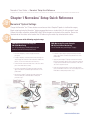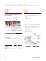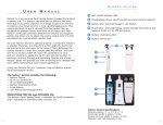
1
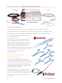
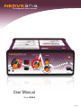
User Manual
Model: NV005.C
NRVM-C
Nerveäna User Guide > Company Information
®
Warning Indications
Warning indications used in this manual and on the Nerveäna® equipment.
Indicator
Meaning
Class II Device.
Attention! Consult accompanying documents.
Type BF equipment.
Warning
The Nerveäna® device has been evaluated to standard IEC 60601-1-1. If the end user connects equipment
not evaluated for use with the Nerveäna® system, they are responsible for ensuring that the equipment
combination meets IEC 60601-1-1.
Support:
www.nerveäna.com
Phone 866-815-6999
or
[email protected]
Neurovision™ Medical Products
2225 Sperry Ave.
Ventura, CA 93003 U.S.A.
tel: (866) 815-6999
fax: (877) 330-1727
www.neurovisionmedical.com
© Neurovision™ Medical Products, 2013
2
www.nerveäna.com
Nerveäna User Guide > Table of Contents
®
Table of Contents
Company Information/Warning Indications ................................................
Table of Contents ........................................................................................
2
3
Chapter 1
Nerveäna® Setup Quick Reference ........................................ 4
Chapter 2
Getting Acquainted with the Nerveäna® ................................ 7
Chapter 3
Chapter 4
Chapter 5
Appendix
www.nerveäna.com
The Nerve Stimulator ................................................................................ 8
Dissecting Stimulator ................................................................................ 9
The EMG Monitor ........................................................................................ 11
Electrodes
................................................................................................ 11
Nerveäna® Controls and Functions ........................................12
Stimulator Current Control ........................................................................
Signal Amplification
................................................................................
On/Standby ................................................................................................
Volume Control
........................................................................................
Free-Run Alarm
........................................................................................
EMG Alarm Test ........................................................................................
Electrode Off Alarm ........................................................................................
Impedance Measurements ........................................................................
Electrical Power ........................................................................................
Features Accessed Via Personal Computer ................................................
12
12
12
12
12
13
13
13
14
14
Nerve Locator Safety ................................................................................
Operation of the Nerveäna ........................................................................
Additional Considerations ........................................................................
Audio Indications ........................................................................................
Summary Audio and Visual Indications ........................................................
15
15
16
17
18
Thyroidectomy and Parathyroidectomy ........................................................
Parotidectomy ................................................................................................
Submandibular Gland Excision
................................................................
Neck and Skull Base Procedures ................................................................
Otologic Surgery ........................................................................................
19
19
20
20
20
Laryngeal Electrode Intubation Instructions ................................................
Instrument Cleaning
................................................................................
Warnings ........................................................................................................
Troubleshooting
........................................................................................
........................................................
Nerveäna® Technical Specifications
Service ........................................................................................................
Warranty ........................................................................................................
21
25
26
27
28
29
30
Surgical Technique and the Nerveäna® ................................15
Procedure Notes
................................................................19
........................................................................................21
3
Nerveäna User Guide > Nerveäna Setup Quick Reference
®
®
Chapter 1 Nerveäna Setup Quick Reference
®
STEP 1
STEP 2
Nerveäna® System Settings
Charge the Nerveäna® for 12 hours before use and ensure that a Scorpion™ probe is sterilized for surgery.
Begin setup by placing the Nerveäna® battery powered device on a stand within 6 ft. of the patient’s head.
Connect the cable assemblies labeled EMG and STIM to the ports on the back of the machine. Secure the
labeled ends of the cables to the head of the OR table using the metal clips attached to the cables.
Choose from one of the following surgical setups:
EMG Monitoring Electrode Setup for
CN X/RLN Monitoring
Use in Thyroidectomy, Parathyroidectomy and
Anterior Cervical Discectomy and Fusion
• Locate the Dragonfly® or Cobra® laryngeal electrode
peel pouch.
• If using a Dragonfly® electrode, have the Anesthesiologist or
surgeon apply the electrode to the ET tube then intubate the
patient. (see box insert with electrode instructions)
• Connect the blue and red electrode wires to the color coded
ports on the EMG cable assembly.
• Locate the single Tadpole™ hydrogel electrode pouch and
apply to the patient’s forehead using the directions on the
product label.
EMG Monitoring Electrode Setup for
CN VII/Facial Nerve Monitoring
Use in Parotidectomy and Otologic Surgery
• Locate the single Tadpole™ hydrogel electrode pouch and
apply to the patient’s forehead using the directions on the
product label.
• Apply the paired Tadpole™ hydrogel electrode with red and
blue wires alternating, blue to lower lip and lower eyelid, red
to upper lip and forehead. Place the electrodes on the same
side as the surgical dissection.
• Drape the electrode lead wires over the face and plug the
green, red and blue connectors to the color coded ports of the
EMG cable assembly and proceed to step 3.
• Plug the green Tadpole™ hydrogel electrode lead wire into
the color coded port on the EMG cable assembly and
proceed to step 3.
4
www.nerveäna.com
Nerveäna User Guide > Nerveäna Setup Quick Reference
®
STEP 2
®
Continued
EMG Monitoring Electrode Setup for
CN XI/Accessory Nerve Monitoring
Use in Neck Dissection
• Locate the single Tadpole™ hydrogel electrode pouch and
apply to the patient’s forehead using the directions on the
product label.
• Locate the paired Tadpole™ hydrogel electrode pouch and
prep the skin as directed on the product label.
• Apply the pair of Tadpole™ electrodes with red lead wires to
the trapezius area of the shoulder on the same side as
the dissection.
• Apply the pair of Tadpole™ electrodes with the blue lead wires
to the appropriate branches of the facial nerve for additional
monitoring coverage.
• Plug the green, red and blue connectors into the color coded
ports of the EMG cable assembly and proceed to step 3.
www.nerveäna.com
5
Nerveäna User Guide > Nerveäna Setup Quick Reference
®
®
STEP 3
STEP 4
Nerveäna® System Settings
Stimulator Setup
Now press the power button and verify the Nerveäna’s settings
match those shown below.
Battery LED:
Green
• Plug the white connector into the color coded port on the STIM
cable assembly.
Free-Run
Alarm Knob:
Off, Use
as needed
Evoked Event LED:
Flashing Yellow
• Locate the sterile Stimulator Pack (NVSP). Remove the needle
electrode (white wire) and apply subdermaly to the patient’s
shoulder.
• Open the sterile inner pack and drop the red stimulator lead wire
on the scrub table in a sterile manner.
• Instruct the scrub nurse to pass the red connector end of the
stimulator lead wire off of the sterile field.
• Insert the red connector into the color coded port of the STIM
cable assembly.
• Direct the scrub nurse to connect the blue end of the stimulator
lead wire to the post of the blue Scorpion™ probe.
Signal Amplification Knob: 100%
Stimulation Knob:
3.0 - 2.5, CN X/RLN and CN XI Monitoring
2.0 - .5, CN VII Monitoring
• If using a Drytouch™ probe, plug its black connector into the
remaining open STIM port.
• Nerveäna® setup is complete.
Nerveäna® Impedance Guidelines
After the monitor’s electrodes have been applied and connected
to the EMG cable, it is possible to test their connection from the
patient to the machine.
1) Hold test button for six seconds, (24 beeps) and release.
2) Note the three flashing numbers presented in order from
reading 1 to 3.
3) Confirm these numbers are within the parameters listed in the
table below.
Electrode
Using ET tube
Electrodes
Using Hydrogel
Electrodes
6
Reading 1
Reading 2
Reading 3
0.2 - 1.2
2.0 or less
2.0 or less
less than 20
less than 20
less than 20
www.nerveäna.com
Nerveäna User Guide > Nerveäna Setup Quick Reference
®
®
Chapter 2 Getting Acquainted with the Nerveäna
®
The Nerve
Stimulator
The EMG
Monitor
The Nerveäna® System
The Nerveäna® combines a nerve stimulator and an electromyographic (EMG) monitor into an integrated surgical
tool. A dissecting stimulating instrument continuously applies a stimulation pulse to soft tissue while the EMG
monitor detects muscle response evoked by stimulation. Once an evoked EMG is detected the Nerveäna®
produces an audio alarm so the surgeon is able to maintain attention on the surgical field. The Nerveäna®
significantly reduces nerve location time and decreases surgeon stress by simplifying difficult dissections.
www.nerveäna.com
7
Nerveäna User Guide > Getting Acquainted with the Nerveäna
®
®
The Nerve
Stimulator
The EMG
Monitor
The Nerveäna® System
The Nerve Stimulator
The Nerveäna® delivers stimulations at a rate of four negative pulses per second. Every stimulation
delivered to the patient is accompanied by a click audio tone and green flash from the Evoked Event light.
The stimulation intensity is controlled by the knob labeled Stimulation (mA) and has current settings of
0.1 - 5.0 milliampere (mA) marked by 0.5 mA intervals
(there is no 0 mA setting).
™
For evoked EMG, most surgery is begun with a 3.0 mA
setting. The adjustable stimulation intensity function
allows the surgeon to approach the target nerve at a
higher setting with sufficient prospective warning to
help prevent injury. The surgeon should stimulate
directly on the identified nerve using the lower stimulator
settings. The 3.5 - 5.0 mA intensity settings is used for
transcutaneous, Vegus Nerve, or other
far-field stimulation.
Scorpion™ Probes: Rea-Type
Monopolar Stimulators
The Scorpion™ line of monopolar probes are surgical
instruments for concurrent dissection and stimulation of
tissue for nerve location. The stimulation pulse is applied
to the body of the device via a pin that is attached to a
disposable red lead wire running to the positive terminal
of the stimulator cable assembly.
The body of the device has an insulating coating to
prevent electrical shorting that extends to within 2 mm
of the tips. The teeth of the forceps instruments are cut
back above the exposed tips to provide full closure of
the instrument.
8
www.nerveäna.com
Nerveäna User Guide > Getting Acquainted with the Nerveäna
®
®
Use of the Dissecting Stimulator
The forceps are used as a dissector by tunneling through the soft tissues with the tines of the instrument
together, then gently separating the tines to spread the soft tissue. Always test the stimulator on exposed
muscle for visible stimulation and for the audio “tic-tic-tic” alert before proceeding with nerve location.
Nerve tissue has greater integrity than other soft tissues approached by this method. Bands of stronger
connective tissue that are raised between the tines of the instrument may be tested by observing for muscle
movement or EMG activation when continuous EMG monitoring is in use. Tissue that does not stimulate may
be cut at the surgeon’s judgment.
Once the nerve is identified, continuous or prolonged exposure of nerve tissue to stimulation should be
limited to the lowest setting that evokes an EMG response. The stimulation should be removed from the nerve
after activation and the intensity reduced prior to further exploration. After the nerve is exposed, only
intermittent stimulation on the lowest possible intensity should be done to assure the surgeon of continued
functional integrity.
Applying unipolar cautery or electrosurgical equipment to the dissecting stimulator should be avoided as the
heat generated may melt the insulation on the instrument. Bipolar electrocautery and the ultrasonic cautery cause
significantly less noise and may be used between the tines of the dissecting stimulator. The device should not
be used in any fashion other than specified in these instructions.
Use of the Dissecting Stimulator must be done in conjunction with active EMG monitoring and/or active visual
observation for target muscle movement. Muscle movement commonly is seen before the EMG reaches
threshold settings and gives a warning tone. Only a supra-threshold muscle response (compound action
potential) will trigger the alarm in the Nerveäna®. This locating system must be considered only as an aid to
the surgeon and not as an excuse to relax vigilance or care in prevention of nerve injury. No device can replace
sound surgical judgment.
Scorpion™ Probes Sterilization Instructions
The insulated coating on the Dissecting Stimulator is extremely rugged and difficult to remove from the
instrument. Short cycle cooling times causes the insulation to crack from the rapid rise in temperature.
We recommend only the following steam sterilization methods with our coated instruments.
Neurovision™ Medical Products sells instrument trays for use in sterilization and storage. An appropriate sized
polyethylene/Tyvek (or equivalent) sterilization pouch of the appropriate size may be used to sterilize
single instruments. Ensure that the pack is large enough to contain the instrument without stressing the seals
or tearing the packaging.
www.nerveäna.com
9
Nerveäna User Guide > Getting Acquainted with the Nerveäna
®
®
Instructions for Steam Sterilization of Stimulating Instruments
Steam Autoclaving with Prevacuum
If a wrapping method is used, make certain that the instruments are individually wrapped or sealed in a sterile
pack. Other metal objects should never come in contact with the insulating material. Such points of contact may
cause melting of the insulation. Position all hinged instruments with latches open and with tips spread and all
surfaces exposed.
We recommend the following values/parameters but we also suggest following the manufacturer's instructions
for steam sterilization:
Cycle Sterilizing
PREVAC 270°F (132°C)
Sterilizing Time
4 min.
Drying Time
30 min.
It is important that the longest drying cycle possible is employed, to prevent build-up of moisture inside the
instrument. A minimum 30 minute drying time is required. Corrosion, pitting or intermittent operation are usual
signs of a moisture induced problem.
Flash Autoclaving (immediate use sterilization)
Flash autoclaving will reduce the useful life of the instrument particularly when it is constructed of various
materials, encompassing different expansion rates. Flash autoclaving is not recommended for typical use.
Chemical Sterilizing, Sterrad and Sterris sterilization processing are not recommended for
stimulating instruments.
10
www.nerveäna.com
Nerveäna User Guide > Getting Acquainted with the Nerveäna
®
The Nerve
Stimulator
®
The EMG
Monitor
The Nerveäna® System
The EMG Monitor
Evoked (Beep) Alarm - A Nerve Locator
The Nerveäna® is designed to detect muscle movement with surface recording electrodes. The electrodes record
electromyographic (EMG) signals generated by contracting muscle. The Nerveäna® is designed to detect evoked
movement which occurs when the nerve innervating the monitored muscle is activated by the machine’s
stimulation pulse.
Free-Run (Chirp) Alarm - A Nerve Monitor
The Free-Run EMG alarm allows the surgeon to
monitor the nerve for a response caused in the
absence of electrical stimulation.
Laryngeal
Surface
Electrode
EMG Electrodes
The Nerveäna® uses two types of surface electrodes
as sensors for evoked muscle activity: a hydrogel
electrode for skin application and a unique laryngeal
surface electrode developed by Neurovision™
Medical Products for detecting EMG signals from
the vocal cords.
The EMG electrodes are placed as appropriate for
the procedure to be performed (see setup instructions).
Care should be taken to follow the specific use
information for each electrode found with the
electrode packaging.
www.nerveäna.com
Hydrogel Electrode
Laryngeal
Surface
Electrode
11
Nerveäna User Guide > Getting Acquainted with the Nerveäna
®
®
Chapter 3 Nerveäna Controls and Functions
®
The Nerveäna® control panel
For a tabular summary of all audio and visual indications see chapter 4.
Stimulation - Current Controls
This knob sets the stimulation current delivered by the stimulating instrument. The settings range
from .1 mA to 5.0 mA.
Signal Amplification - Alarm Trigger Level
The Nerveäna® will only alarm if the muscle action exceeds the detection level set by the signal amplification
knob. The higher setting corresponds to more sensitive EMG detection (a weaker muscle response will trigger
the alarm). This knob should be placed at the highest setting (100%) at the beginning of each surgical procedure
and is adjusted downward only if needed.
On / Standby
The On / Standby button switches the Nerveäna® on and off. The on status is indicated by the Evoked Event light
being lit. When turned off, the event light is not lit.
Volume Control
This is the master volume control for all audio signals.
Free-Run Alarm (Chirp) Knob
The Free-Run Alarm Knob is turned off at the extreme counter-clockwise position. When the Free-Run Alarm is
set in the off position, only the evoked nerve location beep alarms will be active. Turning clock-wise past the
off position activates the Free-Run alarm feature. A chirp alarm tone activated by an adjustable voltage
threshold for integrity monitoring. The Free-Run alarm threshold varies between 1 and 250 microvolts and is
adjusted upward by turning the knob clockwise.
12
www.nerveäna.com
Nerveäna User Guide > Nerveäna Controls and Functions
®
®
EMG Monitor Alarm Test
Depressing the Test button with the Signal Amplification knob set at 100% generates an internal simulated
evoked EMG signal (compound action potential) that verifies the function of the EMG detection circuitry. A
successful test is indicated by repeated alarms and the Evoked Event light flashing red. If depressing the test
button generates no alarm while the Signal Amplification is set to 100%, the machine is improperly configured
or malfunctioning and should not be used.
Electrode Off Alarm
When an electrode connected to the EMG monitor is not in contact with the patient, a burst of four beeps
will sound every minute. Nerve location by the Nerveäna® is not possible when there is an electrode off.
This condition is considered abnormal operation of the monitor and should be corrected. If the operator
continues to use the stimulator with the EMG detector in this non-functional condition, the audio ticks
that indicate stimulus delivered are modified to a distinctive double tick.
Impedance Measurements
Each time the test button is depressed for several seconds, a digital impedance measurement of the electrode
is performed. The results are displayed by three numbers serially flashing in the two digit display labeled
Impedance (kΩ). Impedance measurements are used only for troubleshooting purposes.
Checking Electrode Impedance
To check the impedance of the EMG surface electrodes, depress and hold the test button for at least six
seconds. The first number shown on the digital display is the impedance across the positive (+) and
negative (-) electrode leads. After the test button is released, a second and third number are displayed
providing first the impedance of the positive (+) and then the negative (-) lead to the ground electrode.
The following table is a guide for optimum impedance ranges (measured in kOhm). The Nerveäna® can
operate properly outside of these ranges but if performance problems occur with the EMG detector,
impedance should be checked and adjusted to match these guidelines.
Nerveäna® Impedance Guidelines
Electrode
Reading 1
Reading 2
Reading 3
Using Laryngeal
Electrodes
0.2-1.2
2.0 or less
2.0 or less
Using Hydrogel
Electrodes
less than 20
less than 20
less than 20
www.nerveäna.com
13
Nerveäna User Guide > Surgical Technique and the Nerveäna
®
®
The Nerveäna back panel
®
Electrical Power
The Nerveäna® is designed to run from an internal battery. A large
battery capacity allows operation for about ten hours before recharging
is needed. The machine will operate from wall current if necessary.
The light labeled Battery indicates the status of the battery. A green
light indicates a sufficiently charged battery. A yellow light indicates
a low battery level. A red light, accompanied by a long beep, indicates
a critically low battery level.
The Nerveäna Fixed Height Cart
®
Software for Nerveäna
®
The power supply/charger included with the Nerveäna® should be
plugged into the port on the back left of the device labeled Battery
Charger. The green light labeled AC Power indicates that the
Nerveäna® is connected to an external power source. If the device is
connected to an external power source, this light will be on regardless
of whether the Nerveäna® is turned on or not. If the batteries are
charging, the Battery light will be either yellow or red indicating the
status of the batteries. If the battery is fully charged, the Battery
light will be green when disconnected from wall power.
To ensure a full battery charge, the regulated power supply and charger
should be attached to the Nerveäna® overnight prior to use. If needed,
the Nerveäna® can run in Alarm mode from an external power source
during surgery.
EMGView Software for PC
®
The Nerveäna® is designed to connect to a PC for a graphic display of the
waveforms, the saving of recorded information or to perform diagnostic
checks on the machine. The port labeled USB Out, found on the back of
the Nerveäna® fits a standard USB cable. The cable out is in turn connected
to a PC. Neurovision’s EMGView® software for Windows PCs must be
installed on the computer prior to use.
The Nerveäna Adjustable Height Cart
®
14
www.nerveäna.com
Nerveäna User Guide > Surgical Technique and the Nerveäna
®
®
Chapter 4 Surgical Technique and the Nerveäna
®
Nerve Locator Safety
The Nerveäna® is designed to be a surgical tool in the hands of a competent surgeon. The nerve locating
function of this device is not a substitute for prudent surgical technique and judgment. The Nerveäna® can only
provide positive location of a nerve. Negative location (i.e. determining that the target tissue is not nerve) is
beyond the ability of current technology. The possibility of device malfunction, pharmacologic or physical
depression of nerve conduction, unknown electrode displacement, or other system dysfunction can never be
excluded.
Surgeons who are hesitant to use unfamiliar electronic nerve locating equipment may gain experience by
waiting to initiate use of the Nerveäna® until the nerve has been found anatomically. With the nerve in sight,
the equipment can be turned on and tested against the various tissues.
A wide range of settings for the stimulator and EMG detector and the ability to use many surgical instruments
as stimulators allow the surgeon to customize use of the Nerveäna® to accommodate their surgical technique.
Operation of the Nerveäna®
Set up the Nerveäna® system according to the instructions found in Chapter 1 of this manual or the small
reference provided with each Single-Use Surgery Kit. Verify that no long acting paralytics have been
administered that would inhibit EMG response. Do not use Nerveäna® equipment in the presence of flammable
anaesthetic mixture, with air, oxygen or nitrous oxide.
Proceed with the surgery by normal anatomic dissection. Confirm the delivery of stimulation by observing fine
twitches in muscles brought into contact with the dissecting stimulator. When the soft tissue depth to the target
nerve becomes less than 5 mm, alarms may begin to replace the clicking sound of the dissecting stimulator.
The Nerveäna’s® alarm indicates that stimulation pulses excited the target motor nerve and produced an evoked
EMG response in the muscles monitored by the EMG electrodes. The Nerveäna® will only alarm if the muscle
action exceeds the detection level set by the Signal Amplification Knob. The higher percentage setting
corresponds to more sensitive EMG detection (a weaker muscle response will trigger the alarm).
www.nerveäna.com
15
Nerveäna User Guide > Surgical Technique and the Nerveäna
®
®
Operation of the Nerveäna® (Cont.)
The surgeon may choose to lower the Signal Amplification or Stimulation intensity as the nerve is approached to
limit the number of alarms. Mapping of the nerve’s location prior to direct visualization is possible by narrowing
the area of soft tissue that produces alarms.
After visualization of the nerve has been achieved, lower the stimulation setting and proceed with the
dissection. Whenever working near the nerve, use the lowest intensity stimulation that will evoke an EMG
response. At this setting the nerve should require direct contact with the dissecting stimulator to induce alarms.
Rapid dissection through areas more distant from the nerve can be facilitated by using the dissecting stimulator
on higher stimulation settings.
More precise information on irritiaive response of the nerve can be utilized for the remainder of the dissection if
the Free-Run alarm mode is activated and use of the stimulator is discontinued. In this mode, a Chirp alarm is
produced if the EMG electrodes detect a signal larger than the alarm threshold set by the Free-Run Alarm Knob.
Additional Considerations
When the Signal Amplification is set low, fine motor movements of the monitored muscle are sometimes seen
prior to generation of an alarm. Occasional false alarms may occur when the monitored muscle is mechanically
moved or because of movement of the patient and wires. Stimulation of a large motor nerve branch can
sometimes cause retrograde conduction that evokes a muscle response and an alarm even though the target
nerve was not directly stimulated. Blood vessels in the dissection field can conduct the stimulating current to
the nerve and when stimulated produce a response similar to nerve tissue. A wet surgical site will dissipate
or shunt the stimulation current. For the most effective use of the stimulator keep the stimulated site free of
blood and other fluids. If a malfunction occurs, stop using the Nerveäna® and consult the troubleshooting
guide of this manual.
Understanding the Audio and Visual Indications
The Nerveäna® is designed such that the primary communication with the surgeon is by audio tones. The
surgeon’s attention remains focused on the surgical site while using the nerve locator. Visual indicators are
provided primarily to assess the function of the machine.
16
www.nerveäna.com
Nerveäna User Guide > Surgical Technique and the Nerveäna
®
®
Audio Indications
Silence
In the absence of electrical stimulation and with the Chirp alarm disabled, the Nerveäna® is silent. Note that the
evoked detection alarm will not sound unless the stimulator is in use.
Ticks
When stimulating with the dissecting stimulator, a ticking sound at a rate of 4 clicks per second is heard with
each delivery of a stimulation pulse. If no tick is heard when the stimulator is in contact with the patient, a
check of the stimulator lead wire and ground connections should be done to correct the problem.
In rare cases, the stimulator will deliver a current below that specified by the stimulator setting. In this instance,
the Nerveäna® will replace the typical ticking sound with a distinctive lower pitched tock sound. (See the
troubleshooting section for more information on this problem.)
If one or more of the EMG sensor’s electrodes is disconnected, a double tick will replace the typical single tick
sound. (See the troubleshooting section for more information on this problem.)
Alarms
If the Nerveäna® detects an evoked response from the monitored muscles a distinctive Beep alarm will be
repeated 4 times per second, replacing the stimulator clicks.
If the Free-Run alarm knob has been turned clockwise, the Chirp alarm is activated. Chirp alarms indicate that a
voltage threshold, set by the knob position, has been exceeded and a soft chirp occurs. Chirp is activated
independently of the evoked stimulation alarm Beep and is superseded by evoked stimulation Beep alarm.
If the Nerveänaʼs® EMG detector has been disconnected from the patient, a rapid train of 4 alarms lasting one
second will sound every minute. All leads from the machine to the electrodes should be checked and the
problem corrected before continuing the surgery.
A Sustained Alarm lasting 2 seconds indicates low battery power. The Nerveäna® should be connected to line
power when in this condition to ensure continuous use.
www.nerveäna.com
17
Nerveäna User Guide > Surgical Technique and the Nerveäna
®
®
Summary of Audio Indications
Nerveäna Condition
Audio
System Ready and Idle
Silent
Full Stimulation Delivered
Ticks (higher pitch)
Partial Stimulation Delivered
Tock (lower pitch)
Stimulation Delivered with EMG Off
Double Ticks
Evoked EMG Detected
Repeating Beep Alarm (replaces ticks)
Voltage Threshhold Exceeded
Repeating Chirp Alarm
EMG Detector Disconnected
Train of 6 Alarms (once per minute)
Critically Low Battery
Sustained Alarm
Summary of Visual Indications
18
Nerveäna Condition
Light
Color
State
Battery Charged
Battery
Green
Steady
Low Battery
Battery
Yellow
Steady
Critically Low Battery
Battery
Red
Steady
120 V Power Supply Connected
AC
Green
Steady
Clinical Indicator
Light
Color
State
System Waiting for EMG Input
Event
Yellow
Flashing
Stimulation Detected (no alarm)
Event
Green
Flashing
EMG Detected (alarm)
Event
Red
Flashing
EMG Detector Disconnected (electrodes or cables)
Event
Red
Steady
www.nerveäna.com
Nerveäna User Guide > Procedure Notes
®
Chapter 5
Procedure Notes
Thyroidectomy and Parathyroidectomy
The laryngeal surface electrode (Dragonfly ® or Cobra ®) must be properly placed and remain in contact with the
vocal cords. Random alarms may indicate the LSE is out of position but often the problem is not identified until
the nerve is obviously being stimulated without triggering the Nerveäna’s® alarm. Correction of the problem
requires repositioning of the electrode by laryngoscopy and according to the laryngeal electrode instruction
found in the appendix of this manual.
Stimulation of the inferior thyroid artery can sometimes cause false alarms and the vessel can be mistaken for
the nerve due to its proximity.
The Nerveäna® can be used to find the superior laryngeal nerve. When dissecting the superior pole of the
thyroid contraction of the external cricothyroid muscle can usually be observed as the nerve is approached.
Alarms may not occur but the mass response of the muscle is readily discernible.
Muscle movement with nerve stimulation can be used to identify the branch of the recurrent laryngeal nerve to
the inferior pharyngeal constrictor muscle.
Parotidectomy
Unnecessary stimulation of a located nerve is to be avoided. However, the Nerveäna’s® lowest stimulation levels
do not cause neuropraxia of the facial nerve.
Small nerve branches that are typically sacrificed in standard dissection may be encountered and preserved
using the Nerveäna®.
Retraction on the gland, a dry surgical site or cool temperatures may cause temporary neuropraxia of the facial
nerve and it may not stimulate. The surgeon may choose to avoid retraction until nerve location is performed or
to dissect out a peripheral branch and work toward the main trunk (neuropraxic portion) of the nerve.
Neuropraxia monitoring can be performed with the Free-Run alarm feature.
For benign mixed and Warthin’s tumors, the surgeon may choose to dissect the mass with a cuff of normal
tissue, using the nerve location power of the Nerveäna® to identify branches of the facial nerve only in the zone
of surgery.
www.nerveäna.com
19
Nerveäna User Guide > Procedure Notes
®
Submandibular Gland Excision
The Nerveäna® is an aid in the location of the marginal mandibular nerve in submandibular gland excision. Often
the facial branches to the platysma are located and displaced out of the surgical field preserving function of the
corner of the mouth. Some difficulty in distinguishing between stimulation of the facial nerve branches and the
platysma muscle directly may be encountered.
Additionally, the EMG detector of the Nerveäna® can be utilized to locate the hypo glossal nerve by placing
needle electrodes into the tongue.
Neck and Skull Base Procedures
The Nerveäna® can be used in various operations of the neck. To target a particular nerve, align the array of
three surface electrodes over the muscle innervated by the target nerve.
For example, in a typical neck dissection, the trapezius muscle is monitored by surface electrodes arrayed over
the junction of the trapezius and the neck, just behind the crest of the shoulder.
The accessory cranial nerve can be identified on either side of the sternocleidomastoid muscle or at the skull
base. The branch to the SCM can be specifically identified or the trapezius branch dissected separately.
Location of the accessory nerve in a posterior triangle lymph node biopsy can be done by use of the Nerveäna®,
but use of local anesthesia requires additional care to prevent nerve paralysis by the local injection.
Otologic Surgery
In ear surgery, the Nerveäna® can be used for facial nerve location in the mastoid bone and in the middle ear.
Monitoring may include the Beep for evoked CAP detection or the Chirp for nonevoked voltage threshold
detection and the most sensitive monitoring of the nerve. Waveform evaluation may be used with a PC. The drill
instrument must be activated as a stimulator for proactive nerve location. Neurovision Medical Products makes
a variety of otologic stimulation probes for use in middle ear or mastoid surgery.
Contact Neurovision™ Medical Products for more information on activating a drill as a nerve locating stimulator
and for using the Nerveäna® in ear surgery.
20
www.nerveäna.com
Nerveäna User Guide > Appendix
®
Appendix
Dragonfly® Single Channel Laryngeal Surface Electrode Intubation Instructions
Reliable performance of Dragonfly® electrodes requires proper positioning. Please follow these instructions
carefully and avoid using long-acting paralytics.
Applying electrode:
1) Choose any non-silicon ET tube and the appropriate electrode based on the ET size chart below:
Dragonfly® Electrode Item Code
LSE500MSP
LSE500MS
LSE500M
ET Tube ID Size
2.0 - 5.5
6.0 - 7.0mm
7.5 - 10.0mm
Before application, the tube should be kept clean and free of any
lubricants or other materials that may inhibit electrode adhesion.
2) Determine the location where the vocal cords will be in contact with
the ET tube after intubation. The middle of the electrode will be applied
at this location with the wires directed toward the mouth. (fig 1)
3) Turn over and straighten the ET tube to expose what will be the
posterior side when intubated. Use of a straightened stylet facilitates
hands-free straightening of the ET tube.
4) Align electrode's midline with the midline of the posterior portion of
the tube. Press electrode down, wrapping it toward the top (anterior)
side of the tube (fig. 2). Press along the entire surface and edge to
ensure proper adhesion.
Note: electrode plates should not touch after wrapping.
Figure 4
Figure 1
www.nerveäna.com
Figure 2
21
Nerveäna User Guide > Appendix
®
Dragonfly® Laryngeal Surface Electrode Intubation Instructions (Cont.)
Intubation*:
1) A small amount of lubricant may be applied to the electrode. Insert the ET tube under direct vision or
with a video laryngoscope so that each vocal cord is touching its respective electrode plate and rests
between the two blue positioning stripes. (fig. 3)
Note: the depth number on the ET tube against the maxillary central incisors before any further positioning
of the patient.
2) Tape the ET tube securely with 2 pieces of tape by wrapping each piece first around the tube and then
securing it to the upper lip. (fig. 4)
3) Tightly secure the breathing circuits so the ET tube will not rotate or be displaced and then verify final
electrode position by laryngoscopy with a #3 Miller Blade or with a video laryngoscope.
4) After final positioning of patient, align ET tube in the middle of the pharynx behind the tongue. The
posterior portion of the ET tube
Dragonfly
Dragonfly
should be directly opposite the
Larngeal Electrode
Larngeal Electrode
(Blue Wire)
(Red Wire)
central maxillary incisor gap at the
EMG
depth number noted after initial
Ground Electrode
(Green Wire)
positioning.
®
®
5) Attach the Blue and Red electrode
lead wires to the + or - EMG
terminals and apply the Green lead
from and EMG reference to the
remaining terminal.
* Intubation with Dragonfly®
electrodes for longer than 8 hours
is not recommended.
Figure 3
22
Stimulator Return
Needle Electrode
(White Wire)
Figure 4
www.nerveäna.com
Nerveäna User Guide > Appendix
®
Appendix
Cobra® EMG Monitoring ET Tube Intubation Instructions
Reliable performance of Cobra™ electrodes requires proper positioning. Please follow these instructions carefully
and avoid using long-acting paralytics.
Choose a Tube:
ET Tube ID Size
6.0mm
7.0mm
8.0mm
Cobra Electrode Item Code
LTE700S
LTE700M
LTE700L
Positioning the electrode:
1) A small amount of lubricant may be applied to the electrode. Insert the ET
tube under direct vision or with a video laryngoscope so that each vocal
cord is touching its respective electrode. (fig. 1)
Note the depth number on the ET tube against the maxillary central incisors before any further positioning of the
patient.
2) Tape the ET tube securely with 2 pieces of tape by wrapping each piece first around the tube and then
securing it to the upper lip. (fig. 2)
Figure 1
www.nerveäna.com
Figure 2
23
Nerveäna User Guide > Appendix
®
Appendix
Cobra® EMG Monitoring ET Tube Intubation Instructions (Cont.)
Cobra® Laryngeal
Electrode (Red Wire)
Cobra® Laryngeal
Electrode (Blue Wire)
EMG Ground Electrode
(Green Wire)
Stimulator Return
Needle Electrode
(White Wire)
3) Tightly secure the breathing circuits so the ET tube will not rotate or be displaced and then verify final
electrode position by laryngoscopy with a #3 Miller Blade or with a video laryngoscope.
4) After final positioning of patient, align ET tube in the middle of the pharynx behind the tongue. The
posterior portion of the ET tube should be directly opposite the central maxillary incisor gap at the depth
number noted after initial positioning.
5) Attach the red and blue electrode lead wires to the + and - EMG terminals and apply an EMG ground.
* Intubation with Cobra® EMG Tube is permissible for up to 8 hours.
24
www.nerveäna.com
Nerveäna User Guide > Appendix
®
Instructions for Maintaining, Cleaning, and Sterilization
Non-disposable Stimulation Instruments
Cleaning Procedures
Remove excess body fluids and tissue with a disposable, non-shedding wipe and cover with a damp cloth. Body
fluids and tissue should not be allowed to dry on instruments prior to cleaning. *System components used on or
near tissues of patients who are known or suspected to be infected with Cruetzfeldt-Jakob disease (a.k.a. TSE,
CJD) should be discarded.
Containment/Transportation
1. Universal precautions for handling contaminated/biohazardous materials should be observed.
2 Instruments should be cleaned within 30 minutes of use to minimize the potential for drying
prior to cleaning.
Preparation of Cleaning Agents
Prepare neutral pH enzyme and cleaning agents (Enzo® Clean or equivalent) at the use-dilution
and temperature recommended by the manufacturer.
Manual Cleaning Procedure
1. Use the neutral pH enzyme soaking solution that has been prepared.
2. Completely submerge the instrument in enzyme solution and allow it to soak for 20 minutes. Use a small,
soft-bristled brush to gently clean the device (particular attention shall be given to crevices, lumens, mated
surfaces and other hard-to-clean areas) until all visible soil has been removed. Lumens should be cleaned with a
long, narrow, soft-bristled brush (i.e. pipe cleaner brush).
Note: The enzyme solution should be changed when it becomes grossly contaminated (bloody and/or turbid).
3. Remove the device from the enzyme solution and rinse in purified water (from one or any combination of the
following processes: ultra-filter, RO, DI and/or distilled) for a minimum of 3 minutes. Thoroughly flush lumens,
holes and other difficult to reach areas.
4. Prepare the neutral pH cleaning (detergent, Prolystica® 2x Enzymatic Cleaner concentrate or equivalent)
solution and place in a sonication unit.
5. Completely submerge device in cleaning solution and sonicate for 10 minutes, preferably at 45-50 kHz.
6. Rinse instrument in purified water (from one or any combination of the following processes: ultra-filter, RO, DI
and/or distilled) thoroughly for at least 3 minutes or until there is no sign of blood or soil in the rinse stream.
7. Repeat Steps 5 and 6 with freshly prepared cleaning solution.
8. Dry the instrument with a clean, disposable, absorbent, non-shedding wipe.
www.nerveäna.com
25
Nerveäna User Guide > Appendix
®
Disinfection
Disinfection is only acceptable as an adjunct to full sterilization for reusable surgical instruments.
See sterilization section in chapter 2.
Inspection/Function Testing
1. Carefully inspect each device to ensure that all visible blood and soil has been removed.
2. Visually inspect for damage and/or wear.
3. Check the action of moving parts (such as hinges and box-locks) to ensure smooth operation throughout the
intended range of motion.
4. Check instruments with long slender features (particularly rotating instruments) for distortion.
Note: If damage or wear is noted that may compromise the function of the instrument, contact
Neurovision™ Medical Products for a replacement.
Warnings
• Never rely on the Nerveäna® to determine any structure is not nerve.
• Avoid cauterization on the dissecting stimulator. Bipolar cautery may be used between the tines.
• Do not cauterize or stimulate near the EMG electrodes.
• Never use the Nerveäna® with longer acting paralytics or local anesthetic.
• Avoid leaving the stimulator in prolonged contact with a motor nerve.
• Never assume that sensor electrodes are properly positioned.
• Application of high frequency surgical equipment near the stimulation probe may result in burns at the
stimulator ground or damage to the Nerveäna® stimulator.
• Operation of Nerveäna® in close proximity to shortwave or microwave therapy equipment may produce
instability in the stimulator output.
• Application of electrodes near the thorax may increase the risk of cardiac fibrillation.
Cleaning Procedures for Nerveäna®
Clean the Nerveäna® unit with a soft cleaning cloth or disposable wipe using alcohol or disinfecting solution. Do
not allow liquid to enter the unit while cleaning. Clean the EMG and STIM cable assemblies with alcohol or tape
remover as needed. Clean the Scorpion® probes with the instrument disinfection procedures and sterilization
instructions in Chapter 4 and Appendix.
Environment Warning
Do not use Nerveäna® equipment in the presence of flammable anaesthetic mixture, with air, oxygen
or with nitrous oxide.
26
www.nerveäna.com
Nerveäna User Guide > Appendix
®
Parts and Accessories
Replacement parts and accessories are available for the Nerveäna® system. Please contact Neurovision™ Medical
Products for more information.
Troubleshooting
Stimulator Problems
Solutions
No tick sound is heard when using
the dissecting stimulator.
Check connections of all cables from the stimulating instrument to the back of the machine.
Ensure needle electrode is placed and properly connected to cable assembly.
No muscle movement is seen
when stimulating.
Muscle should rapidly twitch when in contact with the stimulator. Turn up stimulation
intensity until movement is seen.
If the problem persists follow solutions above.
The low tone indicates that the level of stimulation delivered is lower than
specified by the stimulation intensity setting . Check the needle electrode to
ensure is making good contact with the patient.
The low tick tone replaces typical
clicking sound.
EMG Problems
Solutions
No lights or sound when power switched on.
If not connected to line power, the problem is likely a dead battery.
After connecting the machine to line power, depress and release the on/stand by button and
try to restart the machine.
The Nerveäna® may produce bursts of beeps at one minute intervals indicating that electrode
impedance has gone above the operational levels of the detector.
If all EMG cable and lead wire connections are made and all electrodes appear securely in
place as described in their respective instructions, see the impedance measurement
section below.
The Nerveäna® is designed to detect only evoked EMG. If alarms appear to be random and
not correlated to simulation, follow the steps described for electrode off alarm. If the
problem persists, contact Neurovision Medical Products.
Electrode Off Alarm
The low tick tone replaces typical
clicking sound.
Checking Electrode Impedance
To check the impedance (contact) of the EMG surface electrodes, depress and hold the test button for at least
six seconds. The first number shown on the digital display is the impedance across the positive (+) and negative
(-) electrode leads. After the test button is released, a second and third number are displayed providing first the
impedance of the positive (+) and then the negative (-) lead to the ground electrode.
The following table is a guide for optimum impedance ranges (measured in kOhm). The Nerveäna® can operate
properly outside of these ranges but if performance problems occur with the EMG detector, impedance should
be checked and adjusted to match these guidelines.
Nerveäna® Impedance Guidelines
Electrode
Reading 1
Reading 2
Reading 3
Using Laryngeal
Electrodes
0.2-1.2
2.0 or less
2.0 or less
Using Hydrogel
Electrodes
less than 20
less than 20
less than 20
www.nerveäna.com
27
Nerveäna User Guide > Appendix
®
Nerveäna Technical Specifications
Stimulator
Repetition Rate
Pulse Width
Current
Load
Compliance
Isolated
4 pulses per second (± 1%)
158 ± 5 microsecond
0.1 mA - 5.0 mA (0.5mA steps) (larger ± 0.2 mA or ±10%)
0-1000 Ohms ± 1%, (constant) pulse current, regulated
36V min, 40V max
Designed to meet or exceed IEC 60601-1
EMG Monitor
Lowest Gain
Highest Gain
Bandwidth
Notch Filter
A/D converter
Input Impedance
Compliance
Isolated
x367, A/D range = ± 6.8 mV (± 5%)
x18,608, A/D range = ± 134 microvolt (± 5%)
20 ± 3 Hz - 3,000 ± 300 Hz
2-pole 60 Hz (or 50 Hz), by crystal controlled clock
10 bit, at 18,000 samples per second
10 MegOhm each input to reference
± 300 mV
Designed to meet or exceed IEC 60601-1
Impedance Monitor
Display Range
Accuracy
Current
0.0k - 99k Ohm, over range indication (2 high bars)
larger of ± 0.1k Ohm or 10%
< 10 uA peak at 30 Hz (or 25 Hz)
Data Input/Output
Isolated USB
Requires proprietary PC program; Attach to the USB port of PC only.
Power
Battery
Discharge
Charge Rate
Charge Time
DC Input
AC Adapter
6V, 3.4 Amp-Hour, SLA
10 hours (full charge)
240 ± 25 mA, followed by sustaining 2.5 mA trickle
Approximately equal to time discharging
12 VDC ± 20%, 550 mA max
In: 100-200 VAC, 50/60 Hz, 0.5A. Out: 12 VDC, 1.0 A
Environment
28
Condition
The permissible Environment for shipping, storage and use
Temperature
10˚-40˚ C
Relative Humidity
30-75%
Atmospheric Pressure
700-1060 h”
www.nerveäna.com
Nerveäna User Guide > Warranty
®
Service
The Nerveäna® Unit has no user serviceable parts. Consult Neurovision™ Medical Products for service
request. The cost of service and repair will be based on current hourly labor rates and list price for parts on
the date of the requested service.
Neurovision™ Medical Products will service or replace all products under warranty. Unauthorized service will
void a product warranty.
To initiate repair or replacement, call customer service at 866-815-6999 to request a return authorization
number and shipping address.
No preventative maintenance is required.
Service Warranty
NVM warrants the service and repair of each product to be free from problems in material and workmanship
under normal use and service of the warranty period set forth above and subject to the provisions hereof.
As to the performance of service and repair, the obligations of NVM under this warranty is solely limited to the
following: For a 30-day period following the date of return of the product, NVM will again service and repair any
additional problem, which, in the judgment of NVM, is solely the result of improper or inadequate service or
repair. Cost of such repairs (both labor and materials) will be borne by NVM exclusive of cost of mailing or
freight which is the responsibility of the customer.
The foregoing warranties are in lieu of all other warranties express or implied, including, but not limited to, the
implied warranties of merchantability and fitness for a particular purpose of warranties arising from a course of
dealing or usage of trade.
NVM retains the right to refuse to service or repair any product forwarded to it by customer for service or repair.
Upon such refusal, NVM’s sole obligation to the customer will be the return of the product to the customer at
the customer’s sole cost and expense.
NVM reserves the rights to change, amend, or modify any or all of the items under which it renders product
service and repair.
Storage
If the unit is stored for over three months, consult Neurovision™ Medical Products about battery removal or
recharge battery overnight once per month.
Disposal of Unit
The Nerveäna® unit contains a lead acid battery and other possible electronic waste. For disposal in the EU
zone, consult with Neurovision™ Medical Products, Ventura, CA for return of the waste unit.
www.nerveäna.com
29
Nerveäna User Guide > Warranty
®
Warranty
A signed copy of this form must be returned within 30 days to validate warranty. Mail or FAX to:
Neurovision™ Medical, P.O. Box 6895, Ventura, CA 93003 or 877-330-1727.
®
Nerveäna Serial No:_________________ Date of Sale: __________
Purchaser: ________________________________________________
Address: ________________________________________________
City: ________________________________________________
State: ___________________ Zip: _______________________
Phone: (
) __________________________________
To be covered by warranty, you must certify that,
a) Your Nerveäna® will be used only by a licensed physician.
b) All users have carefully read and understood the Operator’s Manual.
c) All users understand that the Nerveäna® is an aid to the surgeon and cannot replace good
surgical judgment and technique in nerve location.
d) All unexpected occurrences associated with the Nerveäna® will promptly be reported to
Neurovision™ Medical Products, Inc.
Execute and Return to Validate Warranty:
I accept the terms of this warranty:__________________________________
Print Name/Title: __________________________________
Date: (
/
/
)
..............................................................................................................................
Limited Warranty:
®
Neurovision™ Medical Products, Inc., warrants the Nerveäna nerve locator to be free from problems in
material or factory workmanship in the course of normal use and service. The manufacturer’s obligation under
this warranty is limited to repairing or replacing any part, provided that the unit is returned, unmodified, to
Neurovision™ Medical Products, Inc., and that the problem has occurred within one year of the original date
of purchase. A handling/postage charge will be assessed. Customer must obtain an RMA number from
Neurovision™ Medical Products’ corporate offices prior to returning any products.
This warranty is void if the purchaser has not returned a copy of this document, signed by the responsible
party of the purchaser, and completely executed. Neurovision™ Medical Products, Inc., expressly disavows
any medical liability for the proper or improper use of this device in the performance of operative nerve
location and monitoring. This liability rightly resides with the surgeon alone.
This warranty does not apply (is void) to any Nerveäna unit which has been repaired in any way or modified by
unauthorized personnel, in the judgment of Neurovision™ Medical Products, Inc.; or which has been subject to
misuse, neglect or accident; or which has had the serial number altered or removed.
®
30
www.nerveäna.com
Neurovision Medical Products
™
2225 Sperry Ave. Ventura, California, U.S.A. www.neurovisionmedical.com
Tel: 866-815-6999, Fax: 877-330-1727, e-mail [email protected]
© Neurovision ™ Medical Products, 2013 • US Patent # 7,379,767 US Patent # 7,583,991 • *Cobra ® Patent Pending
An ISO 13485 Certified Company