1
IV E Scottish Health Technical Memorandum 2022 H (Part 1 of 2) C Design, installation, validation and verification AR Medical gas pipeline systems Disclaimer The contents of this document are provided by way of guidance only. Any party making any use thereof or placing any reliance thereon shall do so only upon exercise of that party’s own judgement as to the adequacy of the contents in the particular circumstances of its use and application. No warranty is given as to the accuracy of the contents and the Property and Environment Forum Executive, which produced this document on behalf of NHSScotland Property and Environment Forum, will have no responsibility for any errors in or omissions therefrom. The production of this document was jointly funded by the Scottish Executive Health Department and the NHSScotland Property and Environment Forum. NHSScotland, P&EFEx, June 2001 SHTM 2022 (Part 1): Medical gas pipeline systems Executive summary An MGPS is installed to provide a safe, convenient and cost-effective system for the provision of medical gases to the clinical and nursing staff at the point of use. It reduces the problems associated with the use of gas cylinders such as safety, porterage, storage and noise. The guidance given in this SHTM should be followed for all new installations, and for refurbishment or upgrading of existing installations. It is not necessary to apply the guidance retrospectively unless patient or staff safety would be compromised. In this case, the guidance given in this SHTM should be followed. IV E Existing installations should be assessed for compliance with this SHTM. A plan for upgrading the existing system should be prepared, taking account of the priority for patient safety. Managers will need to liaise with medical colleagues and take account of other guidance published by the Department of Health in order to assess the system for technical shortcomings. AR C H This part of Scottish Health Technical Memorandum (SHTM) 2022 looks at issues of design, installation, verification and validation. It covers the user requirements for flow, pressure and diversity and gives technical guidance on the design, installation and accommodation of plant and medical pipeline distribution systems. In addition, this part describes the procedures to be carried out before a medical gas pipeline system (MGPS) can be taken into use. The tests to be carried out at each stage of the installation programme are set out, together with requirements for personnel, instrumentation and documentation required. This part is intended for use by designers, installers, manufacturers, operational managers, engineers, quality controllers, technicians, finance officers and other professionals involved in the day-to-day running of an MGPS. The primary objective of this part is to ensure the provision of safe and reliable MGPS and their efficient operation and use. This objective will only be achieved if the medical and nursing users and estates staff participate in the introduction of an operational policy designed to minimise the hazards likely to arise from misuse of the system. Version 2.0: June 2001 Page 2 of 264 © Borders General Hospital NHS Trust on behalf of NHSScotland Property and Environment Forum SHTM 2022 (Part 1): Medical gas pipeline systems Contents Scope Guidance in this document Other guidance Design installation and testing 2. 2.1 2.8 2.11 General principles page 16 General statement Quality requirements for medical gases and air Odour and moisture 2.11 Odour 2.13 Moisture Pipeline distribution system design Safety Installation/supply of equipment/maintenance Modifications Removal of pipework Validation and verification General fire precautions 2.30 General 2.32 Fire detection system Electricity supply to medical gas installations 2.33 General 2.40 Earthing 2.42 Installation of electrical cables 2.45 Electrical wiring in plantrooms Electrical supply pendants 2.49 Ceiling pendant fittings – rigid, multi-purpose type 2.50 Bed head trunking/walling system AR C 2.33 H 2.16 2.19 2.24 2.25 2.28 2.29 2.30 page 15 IV E 1. 1.1 1.6 1.7 2.49 3. 3.1 3.18 3.19 4. 4.1 4.10 Provision of terminal units General Terminal units for nitric oxide, oxygen/carbon dioxide mixture Nitrogen for surgical tools page 24 Gas flow General Gas flow 4.10 Terminal unit flows 4.13 Pipeline flows page 35 Version 2.0: June 2001 Page 3 of 264 © Borders General Hospital NHS Trust on behalf of NHSScotland Property and Environment Forum SHTM 2022 (Part 1): Medical gas pipeline systems 4.49 4.63 AR C 4.71 IV E 4.40 4.43 4.47 Oxygen 4.21 In-patient accommodation 4.27 Hyperbaric oxygen chambers 4.28 Operating departments 4.32 Intensive therapy and coronary care units 4.36 Maternity Nitrous oxide Nitrous oxide/oxygen mixtures Medical air 4.47 General Medical air 400 kPa 4.49 General 4.55 Pressure requirements 4.59 In-patient accommodation Surgical air 700 kPa 4.63 Flow and pressure requirements for 700 kPa surgical air system 4.66 Diversity 4.68 System capacity 4.69 Terminal units intended for equipment testing Vacuum 4.71 In-patient accommodation 4.75 Operating departments 4.82 Intensive therapy unit, coronary care unit and neonatal unit H 4.21 5. 5.1 5.23 5.33 System design – General Cylinder manifold installation 5.1 General 5.9 Pressure control 5.14 Manifold monitoring and indicating system 5.16 Manifold control unit 5.17 Manifold monitoring 5.18 Manifold indication unit 5.19 Alarm signal status unit Emergency reserve supply 5.23 General 5.31 Emergency reserve supplies for manifold installations Emergency reserve supply for air compressors/liquid oxygen/oxygen concentrators (PSA) 5.34 Location Version 2.0: June 2001 page 51 Page 4 of 264 © Borders General Hospital NHS Trust on behalf of NHSScotland Property and Environment Forum SHTM 2022 (Part 1): Medical gas pipeline systems 5.35 System design – Oxygen supplies page 59 Bulk liquid oxygen systems and vacuum insulated evaporator (VIE) 6.1 General 6.5 System sizing 6.9 Equipment description 6.10 Standby oxygen facility 6.11 System layout 6.12 VIE 6.15 Control piping and instrumentation 6.17 Pressure raising system 6.19 Direct reading contents gauge and telemetry systems 6.26 Control panel 6.27 Sites for liquid oxygen storage 6.30 Operation 6.32 Standby system in use 6.35 Standby low 6.36 Low line pressure 6.37 High line pressure 6.39 VIE filling 6.40 Maintenance 6.42 Standby oxygen facility 6.45 Backup bulk liquid storage vessel 6.48 Liquid cylinder backup 6.50 Compressed gas cylinder backup 6.52 Emergency supply facility 6.58 Alarm signal status unit Liquid oxygen supplies from cylinders 6.62 General 6.65 Liquid cylinder design 6.67 Liquid cylinder manifolds 6.69 Control panel 6.71 Emergency compressed oxygen manifold 6.72 Siting requirements 6.82 Liquid cylinder manifold sizing 6.84 Refilling 6.85 Alarm signal status unit Oxygen concentrator installations (PSA plant) 6.89 General 6.94 Siting 6.98 Plant configuration AR C H IV E 6. 6.1 Design 6.62 6.89 Version 2.0: June 2001 Page 5 of 264 © Borders General Hospital NHS Trust on behalf of NHSScotland Property and Environment Forum SHTM 2022 (Part 1): Medical gas pipeline systems 6.100 6.102 6.104 6.105 6.106 6.107 6.111 6.115 6.116 6.117 6.119 6.120 6.124 6.129 IV E System design – Medical air Compressor systems for 400 kPa medical air 7.1 General 7.2 Quality 7.3 Siting 7.7 Compressor noise 7.9 Air intake 7.10 Compressor types 7.13 Compressor lubrication 7.21 After-coolers 7.22 Receivers 7.24 Air treatment and filtration 7.24 General 7.25 Solid contaminants 7.29 Water 7.31 Oil 7.39 Dryer controls 7.40 Dust filters 7.42 Activated carbon filter 7.43 Bacteria filters 7.44 Pressure control 7.45 Test point 7.46 Safety valves 7.48 Traps and valves 7.48 Automatic drainage traps 7.50 Non-return valves 7.51 Isolating valves page 89 AR C H 7. 7.1 Compressors and vacuum pumps Compressor noise Molecular sieves Dryers Oxygen monitoring system Operating and indicating system Plant control unit Plant control indication Compressor and vacuum starter units Molecular sieve control unit Plant status monitoring Plant indicator unit Alarm signal status unit Plant management Version 2.0: June 2001 Page 6 of 264 © Borders General Hospital NHS Trust on behalf of NHSScotland Property and Environment Forum SHTM 2022 (Part 1): Medical gas pipeline systems 7.52 Pressure indicators Operating and indicating system 7.61 Plant control unit 7.64 Plant control indication 7.65 Compressor starter units 7.66 Dryer control unit 7.68 Plant status monitoring 7.69 Plant indicator unit 7.72 Alarm signal status unit 7.77 Plant management 7.78 Operating considerations Synthetic air 7.79 General 7.88 System description 7.95 Storage vessels 7.95 Vessel summary 7.96 Vessel operating pressure 7.97 Main vessel capacity 7.98 Backup vessel capacity 7.104 Vaporisation 7.109 Medical oxygen flow control 7.110 Surgical nitrogen flow control 7.112 Control panel for the nitrogen and oxygen supplies to the mixing panels 7.116 Air mixing panels 7.121 Buffer vessels 7.124 Alarm signal status unit 7.128 Emergency supply facility 7.53 AR C H IV E 7.79 8. 8.1 8.9 8.11 8.13 System design – surgical air 700 kPa page 112 General Cylinder manifold supply systems Compressor supply systems Operating and alarm system 8.13 Cylinder manifold supply system 8.13 Manifold monitoring and indicator system 8.14 Manifold monitoring 8.15 Manifold indicator unit 8.16 Alarm signal status unit 8.20 Compressor supply system 8.21 Plant status monitoring 8.22 Plant indicator unit Version 2.0: June 2001 Page 7 of 264 © Borders General Hospital NHS Trust on behalf of NHSScotland Property and Environment Forum SHTM 2022 (Part 1): Medical gas pipeline systems 8.30 8.31 8.32 System design – medical vacuum supplies Medical vacuum supplies 9.1 General 9.9 Siting 9.11 Pump noise 9.13 Vacuum plant exhaust 9.16 Efficiency 9.18 Vacuum pumps 9.35 Pressure control 9.37 Valves 9.39 Pressure regulation of vacuum system 9.42 Vacuum indicators 9.44 Electrical supply 9.45 Pump operating and indicating system 9.45 General description 9.49 Plant control unit 9.53 Plant control indication 9.54 Pump starter units 9.55 Plant status monitoring 9.56 Plant status indicator unit 9.58 Alarm signal status unit 9.62 Plant management page 118 AR C H IV E 9. 9.1 8.25 Alarm signal status unit Plant management Operating considerations Simplex plant 10. 10.1 System design – anaesthetic gas scavenging systems page 129 Anaesthetic gas scavenging systems 10.1 General 10.10 Background 10.18 Sources of pollution and provision of AGS systems 10.32 AGS system design 10.32 General 10.35 Active and passive systems 10.40 General design requirements 10.46 Safety criteria 10.48 Performance criteria 10.51 Flow diversity 10.52 Discharge outlet Version 2.0: June 2001 Page 8 of 264 © Borders General Hospital NHS Trust on behalf of NHSScotland Property and Environment Forum SHTM 2022 (Part 1): Medical gas pipeline systems 10.53 10.54 Duplex system Plant control indication System design – Nitric oxide page 140 Nitric oxide pipeline installations 11.1 Introduction 11.5 Design considerations 11.10 Provision of terminal units, valves and area valve service units (AVSUs) 11.14 Manifold 11.22 Provision of valves 11.24 Provision of AVSUs 11.28 Pipeline distribution 11.29 Identification 11.30 Alarm systems 11.32 Nitric oxide – risk assessment for COSHH compliance 11.38 Validation and verification 12. 12.1 12.7 Warning and alarm systems General Panel location 12.7 Central indicator panel 12.8 Repeater indicator panel location 12.9 Area warning and alarm panel location System description 12.10 System components System layout 12.11 Central system 12.12 Area warning and alarm systems General requirements 12.13 Labelling 12.14 Visual signals 12.17 Audible signals 12.18 Automatic re setting 12.19 Temporary muting 12.20 Continuous muting 12.21 Electrical wiring 12.22 System integrity 12.25 Relay condition 12.26 Mains power supply 12.27 SELV/FELV power supply 12.30 Test facility page 146 AR 12.10 C H IV E 11. 11.1 12.11 12.13 Version 2.0: June 2001 Page 9 of 264 © Borders General Hospital NHS Trust on behalf of NHSScotland Property and Environment Forum SHTM 2022 (Part 1): Medical gas pipeline systems 12.37 12.49 12.54 AR C H 12.59 Warning and alarm system faults 12.31 General 12.32 Line fault 12.33 Communication/wiring fault 12.34 Mains power failure 12.35 Standby battery 12.36 Legend Indicator panel requirements for all systems 12.37 Indicators 12.40 Labelling 12.41 Construction 12.48 Remote audible sounder Central indicator panel requirements 12.49 Displays 12.50 Mute functions 12.53 Panel legend and display Repeater indicator panel requirements 12.54 Displays 12.55 Mute functions 12.58 Panel legend and display Area warning and alarm panel 12.59 Displays 12.60 Mute functions 12.62 Panel legend and display 12.63 Location IV E 12.31 13. 13.1 13.9 13.15 13.18 Pipeline installation Accommodation of pipes Pipeline materials 13.10 Quality 13.12 Pipes 13.14 Other fittings Cleaning 13.15 Pipes 13.16 Pipe joining fittings Pipeline jointing 13.18 General 13.27 Jointing methods 13.30 Pipe preparation 13.31 Use of N2 internal inert gas shield 13.31 Application 13.33 Safety Version 2.0: June 2001 page 161 Page 10 of 264 © Borders General Hospital NHS Trust on behalf of NHSScotland Property and Environment Forum SHTM 2022 (Part 1): Medical gas pipeline systems AR 13.81 13.82 13.83 13.84 13.86 IV E 13.55 13.61 13.62 13.67 13.68 13.70 13.75 H 13.39 13.40 13.45 13.46 13.52 13.54 C 13.36 13.34 Control cylinders 13.35 Other installation processes Inspection of joins 13.37 Internal cleanliness 13.38 Penetration Capping Removal of flux residues and oxides Purging with the working gas Pipe supports Identification of pipelines Pipeline fittings 13.54 General Ceiling pendant fittings rigid, multi-purpose type Flexible pendant fitting Bed head trunking/walling system Shut-off valves Provision of valves Area valve service units (AVSUs) Provision of AVSUs 13.75 General 13.79 Labelling Pressure sensors Pressure gauges Test points Emergency inlet port Line pressure alarms and safety valves 14. 14.1 14.11 14.14 14.22 14.23 15. 15.1 15.14 Accommodation Design and construction of plantrooms 14.1 Location of plantrooms 14.7 Access Construction and layout of manifold rooms Heating and ventilation of plantrooms Lighting Noise control page 176 Validation and verification General Summary of tests 15.14 Tests and checks on the pipeline carcass 15.15 Test on the pipeline system 15.16 Tests before use page 180 Version 2.0: June 2001 Page 11 of 264 © Borders General Hospital NHS Trust on behalf of NHSScotland Property and Environment Forum SHTM 2022 (Part 1): Medical gas pipeline systems 15.37 C AR 15.79 15.86 15.88 H IV E 15.44 15.17 General requirements for testing 15.17 General 15.29 Modifications, extensions or repairs to existing systems Requirements for pipeline carcass tests 15.37 Labelling and marking 15.38 Sleeving and supports 15.39 Leakage 15.43 Cross-connection Requirements for pipeline system tests 15.44 Leakage from total compressed medical gas systems 15.49 Leakage into total vacuum systems 15.50 Closure of area valve service units 15.54 Zoning of AVSUs and terminal unit identification 15.58 Cross-connection 15.63 Flow and pressure drop at terminal units 15.64 Mechanical function of terminal units 15.65 Gas specificity of terminal units 15.66 NIST connectors 15.68 Performance tests of the pipeline system 15.72 Functional tests of supply systems 15.74 Pressure safety valves 15.76 Warning systems 15.78 Verification of as-fitted drawings Filling with medical air Purging and filling with specific gases Quality of compressed medical gas systems 15.88 General 15.95 Particulate matter 15.97 Oil 15.99 Water 15.101 Carbon monoxide 15.102 Carbon dioxide 15.104 Nitrogen 15.105 Pipeline odour Gas identification Requirements before a MGPS system is taken to use 15.111 General Operational policy Cylinder storage and handling Removal of construction labels 15.106 15.111 15.115 15.116 15.117 Version 2.0: June 2001 Page 12 of 264 © Borders General Hospital NHS Trust on behalf of NHSScotland Property and Environment Forum SHTM 2022 (Part 1): Medical gas pipeline systems AR C H IV E 15.118 Anaesthetic gas scavenging systems 15.118 General 15.123 Performance tests: disposal systems 15.123 Powered device 15.125 Pipework/ductwork installation 15.127 Performance testing 15.132 Receiving system 15.134 Performance efficiency 15.140 Methods and procedures for validation and verification of medical gas pipeline systems 15.140 General 15.146 Labelling and marking 15.148 Sleeving and supports 15.150 Leakage 15.154 Cross-connection 15.157 Leakage from compressed medical gas systems 15.160 Leakage into vacuum system 15.163 Closure of AVSUs 15.166 Zoning of AVSUs 15.170 Cross-connection 15.174 Functional tests of terminal units 15.177 Performance tests of the pipeline system 15.180 System supply tests 15.184 Safety valve inspection 15.187 Warning system tests 15.191 Verification of drawings 15.193 Filling with medical air 15.197 Purging and filling with specific gas 15.200 Tests for quality 15.203 Tests for gas identity 15.206 System taken into use Appendix 1: Testing, commission and filling for use: Forms to be completed during testing and commissioning of piped medical gases systems page 218 Appendix 2: Gas pressure variation with temperature page 236 Appendix 3: Pressure drop test device page 238 Appendix 4: Membrane filter test device page 240 Appendix 5: Equipment for contaminant testing page 242 Version 2.0: June 2001 Page 13 of 264 © Borders General Hospital NHS Trust on behalf of NHSScotland Property and Environment Forum SHTM 2022 (Part 1): Medical gas pipeline systems Appendix 6: Equipment for gas identification page 243 Appendix 7: Procedures for measuring the design flow of vacuum plant page 245 Appendix 8: Procedure for measuring pipeline volume page 246 Appendix 9: Pressure loss data page 248 Appendix 10: Pressure regulation for 400 kPa (medical gases and medical air) and 700 kPa systems (surgical air) page 254 page 257 AR C H IV E References Version 2.0: June 2001 Page 14 of 264 © Borders General Hospital NHS Trust on behalf of NHSScotland Property and Environment Forum SHTM 2022 (Part 1): Medical gas pipeline systems 1. Scope Guidance in this document Guidance in this part of Scottish Health Technical Memorandum (SHTM) 2022 covers piped medical gases, medical compressed air and medical vacuum installations, and applies to all medical gas pipeline systems (MGPS) installed in healthcare premises. 1.2 An MGPS is installed to provide a safe, convenient and cost-effective system for the provision of medical gases to the clinical and nursing staff at the point of use. It reduces the problems associated with the use of gas cylinders such as safety, porterage, storage and noise. 1.3 The guidance given in this part should be followed for all new installations and refurbishment or upgrading of existing installations. 1.4 It is not necessary to apply the guidance retrospectively unless patient or staff safety would be compromised. In this case, the guidance given in this part should be followed. 1.5 Existing installations should be assessed for compliance with this part. A plan for upgrading the existing system should be prepared, taking account of the priority for patient safety. Managers will need to liaise with medical colleagues and take account of other guidance published by the Department of Health in order to assess the system for technical shortcomings. AR C H IV E 1.1 Other guidance 1.6 Guidance on the provision of MGPS is given in Health Building Notes and Scottish Hospital Planning Notes. Design, installation and testing 1.7 This part of SHTM 2022 deals with the issues involved in the design, installation and testing of an MGPS. 1.8 The standard specification, Model Engineering Specification C11, supports this SHTM. C11 provides details of the extent of the works required and is a procurement specification. 1.9 Whenever appropriate, British Standard specifications should be used. Version 2.0: June 2001 Page 15 of 264 © Borders General Hospital NHS Trust on behalf of NHSScotland Property and Environment Forum SHTM 2022 (Part 1): Medical gas pipeline systems 2. General principles An MGPS is designed to provide a safe and effective method of delivering the required medical gas from the source of supply through a pipeline system to the patient via a terminal unit. 2.2 Each medical gas must be supplied from a separate system, and it is essential that all parts of each system are gas specific to ensure that there is no possibility of cross-connection between any system. A schematic diagram of a typical MGPS is shown in part 2 of this SHTM, ‘Operational management’ (Figure 1). 2.3 Systems for dental air and vacuum are covered in SHTM 2022; Supplement 1, Dental compressed air and vacuum systems, since the requirements are different. However, where anaesthetic gases are administered in dental departments, the guidance given in this SHTM should be followed. 2.4 During the installation stage, extensive tests are carried out to verify that there is no cross-connection. 2.5 Where medical air 400 kPa is to be used for testing surgical tools and other medical equipment, this requirement should be considered at the design stage to ensure that sufficient capacity is available. Details of design flows are given in Chapter 4, ‘Gas flow’. 2.6 2.7 Separate installations should be provided for pathology and general laboratories and workshops, although it is recommended that they are constructed to the same specification as MGPS. They should not be provided with medical gas terminal units. Piped medical vacuum systems are not recommended for infectious disease units. C H IV E 2.1 AR General statement MGPS should not be used to supply pathology departments, general workshops or mechanical services. The 400 kPa medical air system may, however, be extended to those departments where respiratory equipment or surgical tools are serviced, such as in sterile disinfection units (SDUs), electronic and biomedical equipment (EBME) workshops etc. In such cases only, to facilitate the testing and checking of operation of equipment for the different medical gases, all terminal units (excluding vacuum) may be connected to the medical air supply and be provided with simplified alarm facilities and labelled accordingly. Version 2.0: June 2001 Page 16 of 264 © Borders General Hospital NHS Trust on behalf of NHSScotland Property and Environment Forum SHTM 2022 (Part 1): Medical gas pipeline systems Quality requirements for medical gases and air Medical gases supplied from cylinder or liquid sources comply with the appropriate sections of the current edition of the European Pharmacopoeia (Ph Eur). There is currently no Ph Eur for site-generated medical air and oxygen pressure swing adsorber (PSA) systems. The quality specification for medical air is as given in Table 1. 2.9 The introduction of the new Ph Eur for medical air was effective from 1998 and therefore medical air will need to comply with this new specification. The Ph Eur also specifies validation protocols which will need to be adopted. 2.10 The quality of piped medical compressed air, the particulate content, dryness and concentration of impurities, should comply with the requirements for maximum concentrations given in Table 1, which is based on the specification for breathing air in BS EN 132:1991. Information on testing procedures is given in Chapter 15, ‘Validation and verification’. IV E 2.8 Table 1: Quality specification for medical air (for the requirement for dental compressed air refer to the relevant supplement) Specification H Parameter Oxygen C Nitrogen 20.9 +/- 1.0% 78% by inference Practically free from visible particles in a 75l sample Water content – see paragraph 2.13 115 vpm (0.095 mg/l) ( equivalent to dewpoint -40°C at atmospheric pressure) CO 5ppm v/v CO2 500 ppm v/v Oil content (droplet or mist) <0.5 mg/m Odour – see paragraph 2.11 none AR Particulate contamination 3 Note: Similar values apply to other medical gases; see relevant paragraph(s) in appropriate Ph Eur monograph. Odour and moisture Odour 2.11 The odour threshold of measurable particulate matter is approximately 0.3 3 mg/m . 2.12 Some elastomeric materials, such as those commonly used in flexible hose, may have a distinctive odour, particularly when new. Extensive tests have shown that the agents likely to be responsible for the odour are present only Version 2.0: June 2001 Page 17 of 264 © Borders General Hospital NHS Trust on behalf of NHSScotland Property and Environment Forum SHTM 2022 (Part 1): Medical gas pipeline systems in minute (parts per billion) quantities and are considered to be of no toxicological significance. Clearly the odour should not be nauseous. Moisture Similarly, those elastomeric materials have been shown to desorb minute quantities of moisture into the gas stream. The amounts of moisture are very small but, on initial testing, may result in moisture levels slightly in excess of 0.095 mg/l. These slightly raised levels of moisture may persist on initial testing for several months. Extensive tests have shown that these slightly raised levels are of no consequence, and reduce following purging with the working gas or use of the system. 2.14 Bacteria filters should be included in medical compressor systems to reduce the risk of delivering spores or other infectious material to vulnerable patients. 2.15 Micro-organisms can penetrate a bacteria filter if the material is wet. Therefore it is essential that the dryness of the medical air supplied to a bacteria filter is checked regularly (at least every three months) at the test point, using the test equipment specified in Chapter 15. IV E 2.13 2.16 H Pipeline distribution system design The following general information is required in order to design an MGPS: C a. schedule of provision of terminal units; b. design flow rates and pressure requirements at each terminal unit; AR c. diversified flows for each section of the pipeline system; d. total flow. 2.17 2.18 Guidance on deriving and calculating the above parameters is given in chapters 3 and 4 of this part. The definition of “departments”, which may comprise several wards, treatment rooms etc, should be agreed at the project design stage to avoid confusion. Safety 2.19 The safety of MGPS is dependent on four basic tenets: a. identity; b. adequacy; c. continuity; d. quality of supply. Version 2.0: June 2001 Page 18 of 264 © Borders General Hospital NHS Trust on behalf of NHSScotland Property and Environment Forum SHTM 2022 (Part 1): Medical gas pipeline systems Identity is assured by the use of gas-specific connections throughout the pipeline system, including terminal units, connectors, etc, and by the adherence to strict testing and commissioning procedures of the system. 2.21 Adequacy of supply depends on an accurate assessment of demands and the selection of plant appropriate to the clinical/medical demands on the system. 2.22 Continuity of supply is achieved by the specification of a system which (with the exception of liquid oxygen systems which may include a secondary vessel) have duplicate components, and by the provision of an adequate emergency/reserve supply for all systems except vacuum; by the provision of alarm systems, and by connection to the emergency power supply system. Anaesthetic gas scavenging systems (AGSS) and high-pressure surgical air systems are not considered as life-support systems and therefore duplicate components and, in the case of the latter, an emergency/reserve supply system, are not normally required. For operational reasons, reserve air cylinders complete with regulators are usually available for surgical tools in operating departments. 2.23 Quality of supply is achieved by the use of gases purchased to the appropriate Ph Eur requirements or produced by plant performing to specified standards, by the maintenance of cleanliness throughout the installation of the system, and by the implementation of the various testing and commissioning procedures. C H IV E 2.20 Installation/supply of equipment/maintenance The installation of MGPS should only be carried out by specialist firms registered to BS EN ISO 9000 with scope of registration appropriately defined. AR 2.24 Modifications 2.25 Special precautions are required when existing installations are to be modified or extended to ensure that all sections of the pipeline system remaining in use are not contaminated, and that the supply to patients is not compromised. The section to be modified should be physically isolated from the section in use. Closure of isolating valves is insufficient for this purpose. Where area valve service units (AVSUs) have been installed the blanking spades should be used. This isolation procedure is not required when work is to be carried out on individual terminal units. 2.26 Modification of existing systems may be detrimental to the overall performance of the system. In the case of older systems there may be insufficient capacity to permit the system to operate safely with the flows typically encountered in use today. Version 2.0: June 2001 Page 19 of 264 © Borders General Hospital NHS Trust on behalf of NHSScotland Property and Environment Forum SHTM 2022 (Part 1): Medical gas pipeline systems 2.27 Any work involving alteration, extension or maintenance work on an existing system should be subject to the permit-to-work procedure (see the ‘Operational management’ part 2 of this SHTM). Removal of pipework 2.28 Removal and cutting out of redundant medical gas pipelines and equipment can present as great a hazard to patient safety as any other modification. All such removal, including cutting into existing pipelines, capping off and removal of redundant pipeline and equipment, should only be carried out by specialist medical gases contractors. It should not be carried out by demolition contractors. Validation and verification IV E The objective of validation and verification is to ensure that all the necessary safety and performance requirements of the MGPS will be met. Validation and verification procedures will be required for new installations, additions to existing installations and modifications to existing installations. The scope of work will dictate the specific programme required. This is described in more detail in Chapter 3, ‘Provision of terminal units’. H 2.29 General 2.31 The siting and general structural principles for the design of liquid oxygen storage accommodation are given in Chapter 4, ‘Liquid oxygen supplies and VIEs’ and the requirements for plantrooms and gas manifold rooms in Chapter 14, ‘Accommodation’. AR 2.30 C General fire precautions Guidance on cylinder storage and handling is given in the ‘Operational management’ part 2 of this SHTM. Fire detection system 2.32 Smoke or heat detector heads should be installed in the plantrooms, medical gases manifold rooms and (when internal) medical gases cylinder stores in any hospital having a fire detection system in accordance with NHS in Scotland Firecode SHTM 82, ‘Alarm and detection systems’. Electricity supply to medical gas installations General 2.33 The whole of the electrical installation should be carried out in accordance with the extant edition of the IEE Regulations for Electrical Installations. Version 2.0: June 2001 Page 20 of 264 © Borders General Hospital NHS Trust on behalf of NHSScotland Property and Environment Forum SHTM 2022 (Part 1): Medical gas pipeline systems The electricity supply to medical gas installations should be taken from separate circuits from a distribution board which is an “essential” board fed by the emergency generator system. This should also apply to the medical gas alarms. Reference should be made to SHTM 2011; Emergency electrical services. 2.35 Care is required when selecting pipeline routes to prevent the pipes coming into contact with electric cables and wiring, and to minimise the risk of electric shock in the event of a fault on adjacent cables. 2.36 The final connection to any equipment, for example alarm panels or control panels, should be made via an unswitched fused connection unit. 2.37 In the event of power failure or interruption, all systems should continue to operate exactly as before the interruption occurred. For example, except for automatic cycling compressors, dryers, pumps etc, the same compressor and dryer (or vacuum pump) set should be on-line, and for manifold systems the same bank should be running. 2.38 All electrical systems, including plant control systems, should be designed in accordance with EMC Directives to reject spurious radio frequency (RF) or mains noise typically occurring in hospitals, examples being diathermy equipment and current spikes caused by plant start-up. Reference should be made to SHTM 2014; Abatement of electrical interference. 2.39 These systems should also be compatible with emergency electrical supply systems which may be either non-interruptible or interruptible with variable changeover delays. 2.40 2.41 AR Earthing C H IV E 2.34 Pipelines should be bonded to the consumer’s earth terminal as required by Regulation 413-2 of the IEE Regulations. This bonding should be made as near as possible to the point at which the pipeline enters the building from the plant. The size of the bonding conductor should be in accordance with Table 54f of the Regulations. The pipelines should not themselves be used for earthing the electrical equipment. Flexible pipeline connections between the compressors or vacuum pumping plant and the fixed pipelines should be bonded across to comply with this requirement. Flexible connections in the fixed pipelines should not normally be used, but if they are specially approved they should be similarly bonded across. Installation of electrical cables 2.42 Distribution pipelines should preferably be physically separated from the metal sheath and armour of electric cables, as well as from metal conduits, ducts and trunking and bare earth-continuity conductors associated with any electric cables which operate at low voltage or above. Reference should be made to SHTM 2007; Electrical services: supply and distribution. Version 2.0: June 2001 Page 21 of 264 © Borders General Hospital NHS Trust on behalf of NHSScotland Property and Environment Forum SHTM 2022 (Part 1): Medical gas pipeline systems 2.43 When physical separation is impracticable, or where there might be contact with extraneous metal work, for example, where the pipes are carried in metal partitions or where terminal units are mounted on metal bed-head units, the pipelines should be effectively bonded to the metal work in accordance with Regulations 525-10 of the IEE Regulations. 2.44 Where piped gases and electric wiring are enclosed in a boom, gas control panel or other similar enclosure, the wiring should be carried in separate conduit or trunking so that it cannot come into direct contact with the piped gas installation. Where this is not possible, the wiring should be secured in the most effective manner possible, clear of the medical gas pipes. The cables should comply with IEE Regulation 523-17. Electrical wiring in plantrooms All electrical wiring in these rooms should be carried out using MICS cable or cable of the type indicated in IEE Regulation 523-17, with adequate protection against mechanical damage. 2.46 Fire-resistant cable conforming to BS 6387, PVC armoured cables, and single insulated cables in conduit may also be used. 2.47 Each compressor, vacuum pump and manifold should be supplied from a separate sub-circuit. 2.48 Metal-clad sockets, connection units and switches should be used in plantrooms; plastic fittings are not appropriate. C H IV E 2.45 AR Electrical supply pendants Ceiling pendant fittings – rigid, multi-purpose type 2.49 The construction should provide segregation of low voltage, functional extralow voltage (FELV) electrical services by means of flexible partitions or conduit, as appropriate. Access to “live” components should be via panels which are removable by means of tools only. Version 2.0: June 2001 Page 22 of 264 © Borders General Hospital NHS Trust on behalf of NHSScotland Property and Environment Forum SHTM 2022 (Part 1): Medical gas pipeline systems Bed-head trunking/walling system C H IV E These fittings should generally be in accordance with SHTM 2015; Bedhead services. Separate compartments should be provided for electrical services, nurse call/radio etc and medical gas pipelines. AR 2.50 Version 2.0: June 2001 Page 23 of 264 © Borders General Hospital NHS Trust on behalf of NHSScotland Property and Environment Forum SHTM 2022 (Part 1): Medical gas pipeline systems 3. Provision of terminal units General A typical schedule of provision of terminal units is given in Table 2. Medical treatment policy is evolutionary, and therefore the project team should review the requirements for individual schemes. 3.2 Terminal units should be mounted in positions which give the shortest practicable routes for flexible connecting assemblies, between the terminal unit and apparatus. Terminal units may be surface or flush mounted. They may also be incorporated with electrical services, nurse call systems and TV and radio audio services, in proprietary fittings such as bedhead trunking, wall panel systems and theatre pendant fittings, etc. Refer also to SHTM 2015; Bedhead services. 3.3 When planning the installation of theatre pendant fittings, the location of the operating luminaire and other ceiling-mounted devices should be taken into consideration. When the operating room is provided with an ultra-clean ventilation (UCV) system, it may be more practicable (and cost-effective) to have the services (both medical gas and electrical) incorporated as part of the UCV system partial walls. 3.4 The following installations are strongly deprecated: C H IV E 3.1 a. floor-mounted terminal units; 3.5 3.6 AR b. vacuum systems in which body or other fluids are drawn through a fixed pipeline connecting a terminal unit or other connector to a remote vacuum jar. All terminal units should conform to BS 5682:1998. Terminal units intended for installation with the socket axis horizontal, i.e. wall mounted, include a non-swivel device so that directly connected equipment such as flow meters remain vertical; terminal units intended for installation with the socket axis vertical, for example in certain types of pendant, do not include a non-swivel device. Secondary locks are no longer included in terminal units. An anaesthetic gas scavenging (AGS) terminal unit should be provided whenever nitrous oxide is available for anaesthetic procedures. In recovery areas, when nitrous oxide is not provided, where there is no primary source of anaesthetic gas pollution and/or where nitrous oxide is used for analgesic purposes only, no anaesthetic gas scavenging system (AGSS) is required. Where nitrous oxide is provided for analgesic purposes, scavenging is not practicable and pollution should be controlled by mechanical ventilation. Details of ventilation requirements are given in the appropriate Health Building Notes, Scottish Hospital Planning Notes, and Design Guides. Version 2.0: June 2001 Page 24 of 264 © Borders General Hospital NHS Trust on behalf of NHSScotland Property and Environment Forum SHTM 2022 (Part 1): Medical gas pipeline systems NOTE: Reference should be made to EL(96)33 covering publication advice on the implementation of the Health & Safety Commission’s ‘Occupational Exposure Standards for Anaesthetic Agents’ published by the Department of Health, March 1996. Further guidance is given in Anaesthetic agents: Controlling exposure under COSHH, prepared by the Health Services Advisory Committee, ISBN 0- 7176-1043-8. The terminal unit (AGS) is specified in BS EN 737-4: 1998. AGSS are covered in Chapter 10. 3.8 If nitrous oxide is provided in the equipment service room or workshop, an appropriate AGSS must also be provided. 3.9 Medical quality compressed air should be available to at least one workstation in the equipment service room and workshop. Terminal units in accordance with BS 5682:1998 should be provided. The supply should be taken from the medical air pipeline wherever possible. 3.10 Where an anaesthetic equipment testing area is provided, it will be necessary to provide medical gases for the testing and calibration of anaesthetic equipment. A full range of medical gas terminal units will be required, but wherever possible, medical air should be used for testing purposes. If medical air is provided instead of the medical gas, the terminal units must be clearly labelled to prevent confusion: “TEST PANEL – GAS TERMINAL UNITS CONNECTED TO 4-BAR MEDICAL AIR ONLY”. 3.11 Where gas mixers (blenders) are to be tested, it will be necessary to provide the appropriate gases. These may be provided either from the MGPS or from cylinders. 3.13 H C AR 3.12 IV E 3.7 The specific and special requirements for nitric oxide pipeline systems are covered separately in Chapter 11. Where an array of terminal units is provided at a location, they should be arranged as follows: a. for a horizontal array, when viewed from the front, left to right: oxygen, nitrous oxide, nitrous oxide/oxygen mixture (50% v/v), medical air 4-bar, surgical air 7-bar, vacuum, anaesthetic gas scavenging, nitric oxide, oxygen/carbon dioxide mixture: O2, N2O, N2O/O2 , MA-4, SA-7, VAC, AGS, NO, O2/CO2 b. for a vertical array, with oxygen at the top and in the sequence as for a horizontal array. In many cases a vertical array is impracticable and a more convenient arrangement will comprise a number of rows, for example: O2 N2O and/or N2O/O2 MA-4, SA-7, VAC, AGS, NO, O2 /CO2 ; Version 2.0: June 2001 Page 25 of 264 © Borders General Hospital NHS Trust on behalf of NHSScotland Property and Environment Forum SHTM 2022 (Part 1): Medical gas pipeline systems c. for a circular array, for example where terminal units are installed on the under surface of a pendant, with the sequence as for a horizontal array, in a clockwise direction when viewed from below. The AGS terminal unit may occupy the centre of such an array. Mounting heights for terminal units should be between 900 mm and 1400 mm above finished floor level (FFL) when installed on walls or similar vertical surfaces. 3.15 When installed in pendants or similar, terminal units should be of a type suitable for mounting within the specified fitting. 3.16 Pressure losses across terminal units should be in accordance with BS 5682: 1998. (The standard does not give pressure loss data for surgical air at 350 l/min – but see Table 4) AR C H IV E 3.14 Version 2.0: June 2001 Page 26 of 264 © Borders General Hospital NHS Trust on behalf of NHSScotland Property and Environment Forum SHTM 2022 (Part 1): Medical gas pipeline systems Table 2: Scale of provision of terminal units. AR C H IV E Department O2 N2O N2O/O2 MA4 SA7 VAC AGSS Accident and emergency department Resuscitation room 1 1 1 1 1 per trolley space Major treatment room/plaster room per trolley space 1 1 1p 1 1p 1 1 Post-anaesthesia recovery per trolley space 1 1p 1 Treatment room/cubicle 1 1 Operating department 1 1 1 1 1 Anaesthesia room Operating theatre Anaesthetist 1 1 1 1p 2 1 Surgeon 1 1 1 1p 2 1 Post-anaesthesia recovery per bed space 1 1 1 Equipment service room per work space 1 1 1 1p 1 1 Maternity department Delivery suite Normal delivery room Mother 1 1 1 Baby 1 1 1 Abnormal delivery room Mother 1 1 1 1 2 1 Baby 1 1 1 Operating suite Anaesthesia room 1 1 1 1 1 Operating theatre 1 1 1 1 1 Anaesthetist – 1 Obstetrician Paediatrician per cot space (*) 1 1 1 Post-anaesthesia recovery per bed space 1 1 1 Equipment service room(**) per work space 1 1 1 1 1 1 Neonatal unit 2 2 2 per cot space Equipment service room(**) per work space 1 1 1 (*) provision for 2 cots only, irrespective of number of cot spaces (**) Where the delivery suite and Neonatal unit are in close proximity, one equipment service room can be shared. In-patient accommodation 1 1 Single bedroom Multi bedroom 1 1 per bed space Nusery 1 1 per cot space (*) (*) provision for 2 cots only, irrespective of number of cot spaces. p = project team option Version 2.0: June 2001 Page 27 of 264 © Borders General Hospital NHS Trust on behalf of NHSScotland Property and Environment Forum SHTM 2022 (Part 1): Medical gas pipeline systems Scale of provision of terminal units Department Radiology department Special procedures room Anaesthesia room Holding and delivery Ultrasound Fluoroscopy Urography General purpose room Tomography O2 N2O N2O/O2 MA4 SA7 VAC AGSS 1 1 1 1 1 1 1 1 1 1 - - 1 1 1p - - 1 1 1 1 1 1 1 1 1 1 - - - 1p - 1 - - - 1p 1p - 1 1 - 2p 2p 4 - 4 2p In-patient accommodation # 1 Single bed room Multi bed room 1 per bed space 1 Treatment room # appropriate for adult acute, children and elderly Coronary care unit (CCU) per bed space 2 IV E Intensive therapy unit (ITU) per bed space Equipment service room per work space 1p 1p 1 - 1 1p 2 - - 2p - 2 - 1 1 - 1 - 1 1 1 - - 1p - 1 - 1 - 1p - - 1p - - 1 1 1p - 1 - - 1p - 1 - 1 - - - - 1 - 1 1 1 1p - 1p 1p - 1 1 1 1p 1 1 - 1p 1p 1 1 1 1p - 1 - 1 1p 1 - - 1 - 1 - 1 - - - - 1 - - - - - 1 - - H Acute mental illness accommodation ECT room Post-anaesthesia recovery per bed space 1 C Adult acute day care accommodation Treatment room AR Anaesthetist Surgeon Post-anaesthesia recovery Per bed space Day patient accommodation Single bedroom Multi-bedroom per bed space Treatment room (p) Endoscopy room (p) Fracture clinic Plaster room Oral surgery, orthodontic department Consulting/treatment room Type 1 Consulting/treatment room Type 2 Recovery room per recovery position Appliance laboratory per workstation p = project team option Version 2.0: June 2001 Page 28 of 264 © Borders General Hospital NHS Trust on behalf of NHSScotland Property and Environment Forum SHTM 2022 (Part 1): Medical gas pipeline systems Scale of provision of terminal units Department O2 N2O N2O/O2 MA4 SA7 VAC AGSS 1 1p - 1p - 1 1p Washing room - - - 1 - - - Packing room - - - - 1 - - 1 - - 1 - 1 - 1 - - 1 - 1 - Out-patient department Treatment room Sterile services department Medical equipment re-assembly per work station Medical equipment workroom IV E per workstation p = project team option H Note: 1. Nitric oxide Terminal units for nitric oxide may be required as a project team option in intensive therapy units and neonatal units. In exceptional circumstances, nitric oxide may be required in operating departments. The level of provision would be two terminal units for each cot or bed space, and two terminal units per theatre. 3.17 AR C 2. Oxygen/carbon dioxide mixtures Terminal units for oxygen/carbon dioxide mixtures may be required as a project team option in cardio-thoracic theatres and in oncology units. Terminal units which are wall mounted should be located as follows: a. distance between centres of adjacent horizontal terminal units: (i) 135 ± 2.5 mm for three or more terminal units; (ii) 150 ± 2.5 mm for two terminal units only; This should be sufficient for double flow meters to be used, for example between an oxygen terminal unit and a vacuum terminal unit serving two bed spaces; b. the distance between the centre of the terminal unit and a potential obstruction on either side (for example when installed in a corner) should be a minimum of 200 mm on either side. NOTE: Where, in some ward areas, terminal units are installed in recesses behind covers/decorative panels etc, allow an additional 100 mm on each side of the outermost terminal units and 200 mm from centre to top of recess and 300 mm from centre to bottom of recess. The depth of the recess should be 150 mm. Version 2.0: June 2001 Page 29 of 264 © Borders General Hospital NHS Trust on behalf of NHSScotland Property and Environment Forum SHTM 2022 (Part 1): Medical gas pipeline systems Terminal units for nitric oxide, oxygen/carbon dioxide mixture BS 5682 does not include a terminal unit for nitric oxide or oxygen/carbon dioxide mixture. In the absence of standards, the dimensions given are recommended. They are based on the diagrams and tables in BS 5682:1984 as follows: NOTE: BS 5682: 1984 has since been withdrawn and replaced by BS 5682: 1998. Recommended probe dimensions for nitric oxide and oxygen/carbon dioxide mixture (CO2 less than 5%) and NIST dimensions for nitric oxide Diameters of probe Nitric oxide O2/CO2 Identification symbol NO O2/CO2 Diameter D 21.48 18.30 21.38 18.20 25.00 21.83 24.90 21.73 mixture (CO2<5%) C H (CO2<5%) Diameter C IV E Service AR 3.18 Version 2.0: June 2001 Page 30 of 264 © Borders General Hospital NHS Trust on behalf of NHSScotland Property and Environment Forum SHTM 2022 (Part 1): Medical gas pipeline systems H IV E 〈 ØD ØC (a) Dimensions (c) Dimensions of optional locating slot of indexing collar 6 AR C (b) Enlarged section of probe nose Version 2.0: June 2001 Page 31 of 264 © Borders General Hospital NHS Trust on behalf of NHSScotland Property and Environment Forum SHTM 2022 (Part 1): Medical gas pipeline systems Diameters of body of NIST connectors Service Identification symbol Nitric oxide NO Diameter E 11.00 +0.11 -0.0 Diameter F 14.00 +0.11 -0.0 6 6 C 6 ØF H 〈 ØE IV E 6 6 AR 6 Version 2.0: June 2001 Page 32 of 264 © Borders General Hospital NHS Trust on behalf of NHSScotland Property and Environment Forum SHTM 2022 (Part 1): Medical gas pipeline systems Diameters of nipples of NIST connectors Service Identification symbol Diameter J 11.00 –0.05 -0.16 14.00 –0.05 -0.16 H 6 6 6 AR C 〈 IV E NO ØH ØJ Nitric oxide Diameter H 6 6 Version 2.0: June 2001 Page 33 of 264 © Borders General Hospital NHS Trust on behalf of NHSScotland Property and Environment Forum SHTM 2022 (Part 1): Medical gas pipeline systems Nitrogen for surgical tools BS 5682 does not include a NIST for nitrogen. In the absence of a British Standard, the NIST connector allocated in ISO 5359 may be used. 3.20 Where nitrogen is provided for surgical tools, the NIST connector is recommended with the “body” forming the wall outlet. To avoid the hazard of discharge of stored energy in low pressure, flexible, connecting assemblies, a limited leak check valve should be included in the nipple. AR C H IV E 3.19 Version 2.0: June 2001 Page 34 of 264 © Borders General Hospital NHS Trust on behalf of NHSScotland Property and Environment Forum SHTM 2022 (Part 1): Medical gas pipeline systems 4. Gas flow General 4.1 A schematic diagram of a typical MGPS is shown in the ‘Operational management’ part 2 of this SHTM. This diagram shows the pipeline distribution system from the gas source to the point of use that is the terminal units. 4.2 There are three aspects of gas flow to consider when designing the pipeline distribution system: a. the flow which may be required at each terminal unit; IV E b. the flow required in each branch of the distribution system (see the schematic, which shows a system with several main branches); c. the total flow, i.e. the sum of the flows in each branch. The pipeline system should be designed so that the design flows given in Table 4 can be achieved at each terminal unit. 4.4 If all terminal units were in use simultaneously, excessively large pipelines and plant would be required. However, since not all terminal units are used simultaneously, it is necessary to apply a diversity factor to the flow in each branch of the system, to arrive at a realistic design flow. 4.5 The diversity factors used are derived from the results of surveys of actual gas usage in typical hospitals. 4.7 C AR 4.6 H 4.3 The total flow for the system is the sum of the diversified flows to each department. The design engineer should always ensure that due account is taken of the stated use of a particular department. For example, the number of terminal units in use for ward areas may be appropriate for a DGH, but the number may need to be increased for a specialist chest department. The pipeline is required, however, to meet the peak simultaneous demand and is designed accordingly. The source of supply will usually be required to deliver a lower continuous flow. 4.8 It must be remembered that there is a limited range of pipe sizes, and that where there is any doubt about flow requirements, a larger pipe size should always be selected. 4.9 All flows are in normal litres per minute (l/min) unless otherwise stated. Version 2.0: June 2001 Page 35 of 264 © Borders General Hospital NHS Trust on behalf of NHSScotland Property and Environment Forum SHTM 2022 (Part 1): Medical gas pipeline systems NOTE: At the design stage the project team should define the individual room/space required. The definitions which follow are generic and are not as detailed as those given in Table 2. Gas flow Terminal unit flows The following formula is used to calculate the volume flow required in the pipeline at pressure Pg upstream of each terminal unit. Table 4: Gas flow – flows required at terminal units Location Nominal e pressure kPa Flow litres/min Design flow IV E Service a Typical flow required Oxygen Theatre All other areas 400 400 100 c 10 20 6 Nitrous oxide All areas 400 15 6 Nitrous oxide/oxygen mixture Delivery rooms All other areas 275 20 20 15 Medical air 400 kPa Theatres ITU/neonatal CCU Other 400 400 400 400 40 c 80 c 80 20 Theatres 700 350 b 310 400 H C Surgical air/nitrogen AR 4.10 c 40 80 80 c 10 d 350 Vacuum Theatres Recovery CCU Ward areas 40 (300 mm Hg) below atmospheric 40 40 40 40 40 40 40 40 Nitric oxide ITU, neonatal theatres 400 15 6 Oxygen/carbon dioxide mixture Cardio-thoracic theatres, oncology 400 100 40 a. During oxygen flush in operating and anaesthetic rooms. b. Minimum pressure at 275 l/min. c. These flows are for certain types of gas-driven ventilators under specific operating conditions, and nebulisers etc. d. Surgical tools/tourniquets. e. Pressure required at terminal unit, not in pipeline. Version 2.0: June 2001 Page 36 of 264 © Borders General Hospital NHS Trust on behalf of NHSScotland Property and Environment Forum SHTM 2022 (Part 1): Medical gas pipeline systems 4.11 The flow Qa required at a terminal unit is expressed in terms of free air flow at standard temperature and pressure (STP). The relationship between volume flow Qa at STP and the volume flow Qg at the pipeline pressure (Pg) is: Qg = Were Qa × Ap Pg Ap = atmospheric pressure (absolute) Pg = pipeline pressure (absolute) NOTE: For manual calculations based on Table 4, the volume flow is expressed in terms of free air flow Qa and it is, therefore, not necessary to calculate Qg. The flows required at terminal units, as shown in Table 4, are design flows for each terminal unit; the actual pipeline distribution design will be based on the diversified flow rates derived using the methods described in the following paragraphs. IV E 4.12 Pipeline flows Normally, because Pg is considered to be constant throughout the entire pipeline network, the volume flow Qg required in the upstream branch of a T-junction is simply the sum of the volume flows in the downstream branches. 4.14 By simply adding the downstream flows in this way, the resultant total flow is higher than that found in practice and would result in unnecessarily large pipe sizes. Therefore, an allowance for diversity of flow is made. 4.16 AR 4.15 C H 4.13 As discussed earlier, it is difficult to predict diversities accurately, but there are guidelines which can be used and these have been shown to be adequate in practice. For vacuum systems, the minimum vacuum should not fall below 300 mm Hg at each terminal unit at a flow of 40 l/min. 4.17 The design of the pipework system is based on flows and acceptable pressure loss as shown in Table 4 to include terminal unit pressure loss given in Table 23, Chapter 15. The overall consumption may be lower in practice, but the systems would be capable of meeting the calculated demand within an acceptable range, that is, the design flow operating at a nominal pressure of 400 kPa. 4.18 Departments usually comprise several ward units and treatment rooms. In order to avoid confusion, departments should be defined at the project design stage so that diversified flows may be calculated. Version 2.0: June 2001 Page 37 of 264 © Borders General Hospital NHS Trust on behalf of NHSScotland Property and Environment Forum SHTM 2022 (Part 1): Medical gas pipeline systems 4.19 Pressure requirements for surgical air are based on the requirement that the minimum pressure should be 700 kPa at the point of use, that is, the terminal unit at a flow of 350 l/min. 4.20 Details of pressure requirements for all systems are given in Appendix 10. Oxygen In-patient accommodation Oxygen is used at a typical flow of 5–6 litres/min. Each terminal unit should, however, be capable of passing 10 l/min (at STP) at a supply pressure of 400 kPa (nominal) as shown in Table 4, in case nebulisers or other respiratory equipment is used. 4.22 The diversified flow to each six-bed room is calculated on the basis that 10 l/min will be required for the first terminal unit and that only 33% of the flow to the remainder at 6 l/min will be required. This is equivalent to a maximum of three terminal units in use simultaneously in a six-bed room. 4.23 In a typical ward comprising four 6-bed rooms, four single-bed rooms and a treatment room, for the purpose of calculating the diversified flow QW to the ward, the number of terminal units n used in Table 6 may be taken as the total number of terminal units in the ward. 4.24 A department may comprise several ward units and treatment suites where appropriate. The diversified flow for each department, QD, is based on QW for the first ward unit, plus 50% of the flow for the remaining ward units. For the purposes of this calculation, the first ward unit can be taken as the largest ward unit within the department. 4.25 4.26 AR C H IV E 4.21 The formula in Table 6 is based on the assumption that a department comprises a number of identical ward units; where this is not the case, the diversified flow is QW for the first (or largest ward unit) plus 50% of the total for the remaining ward units. If one ward unit is significantly larger than the others, average the flows from the ward units to obtain a more realistic flow. Version 2.0: June 2001 Page 38 of 264 © Borders General Hospital NHS Trust on behalf of NHSScotland Property and Environment Forum SHTM 2022 (Part 1): Medical gas pipeline systems Hyperbaric oxygen chambers Monoplace hyperbaric oxygen chambers for clinical purposes should be supplied from a separate branch. Typical flows for one-person chambers are as shown in Table 5. Table 5: Gas flow hyperbaric chambers Max time for one complete treatment Total consumption for max treatment time (litres) Consumption for each additional minute l/min O2 atmosphere and recirculation on open circuit 2 hours 30,000 250 • on recirculation 2 hours 7,250 40 O2 only; no recirculation 2 hours 30,000 250 O2 delivery by built-in breathing mask and overboard pump 2 hours O2 delivery by built-in breathing hood and overboard pump 2 hours IV E • 1,200 10 7,200 60 C H Note: 1. The flows for a recirculating unit assume the standard method of operation is recirculation throughout the treatment. It is recommended that the pipeline should be designed for open circuit operation to ensure adequate flow under all conditions. 2. Clinical practice may require the inclusion of air during the treatment; it may also be necessary to switch to air in the unlikely event of an oxygen convulsion. Therefore consideration should be given to the provision of medical air. 3. Some hyperbaric chambers use air as a buffer and considerably less oxygen is consumed. The advice of the manufacturer should be sought. AR 4.27 Version 2.0: June 2001 Page 39 of 264 © Borders General Hospital NHS Trust on behalf of NHSScotland Property and Environment Forum SHTM 2022 (Part 1): Medical gas pipeline systems Table 6: Oxygen diversified flows Department Design flow for each terminal unit l/ min Diversified flow Ward units – single and multibedrooms Treatment rooms 10 QW = 10 + Each ward unit Departments comprising several day units 10 QD = QW ITU and CCU 10 QI = 10 + (nB – 1)6 Q l/min In-patient acute 3 1+ (w −1) 2 IV E Adult acute day care (n − 1) 6 100 QT = 100 + 20(T–1) Endoscopy room 10 QR = 10 + (n-1)6 Recovery room 10 QR = 10 + (n-1)6 Maternity department 100 QM = 100 + AR C Delivery suite Normal delivery room Abnormal delivery room H Major treatment room Neonatal unit (n − 1)6 2 10 QN = 10 + (n-1) 6 Operating room 100 QT = 100 + 20(T-1) Anaesthetic room 10 QA = 10 + (A-1) 6 Operating department Version 2.0: June 2001 Page 40 of 264 © Borders General Hospital NHS Trust on behalf of NHSScotland Property and Environment Forum SHTM 2022 (Part 1): Medical gas pipeline systems Legend for all tables Operating departments H The diversified flow for operating departments is based on 100 l/min required for the oxygen flush. Therefore each oxygen terminal unit in the operating room and anaesthetic room should be able to pass 100 l/min. It is unlikely that an oxygen flush will be administered simultaneously in several operating rooms. The diversified flow, QT, is based on 100 l/min for the first operating room and 20 l/min for the remainder. 4.29 AR C 4.28 IV E n = number of terminal units nB = number of bed spaces W = number of ward units T = number of operating rooms or major treatment rooms A = number of anaesthetic rooms S = number of operating suites (1 operating room + 1 anaesthetic room) Q = diversified flow QW = diversified flow to ward units QD = diversified flow to a department QI = diversified flow to ITU or CCU QT = diversified flow to operating room or major treatment room QA = diversified flow to anaesthetic rooms QR = diversified flow to recovery rooms QM = diversified flow to maternity suite QN = diversified flow to neonatal unit QB = diversified flow to baby bed space QDent = diversified flow to dental department QWS = diversified flow to equipment workshop QP = diversified flow to plaster room For anaesthetic rooms, each terminal unit should be capable of passing 10 l/min, but the actual flow likely to be used is 6 l/min. The diversified flow is based on 10 l/min for the first room and 6 l/min for the remainder, since it is possible that all anaesthetic rooms may be in use simultaneously. Recovery is considered in a similar way, since again, it is possible that all bed spaces may be in use simultaneously. To obtain the flow to each operating suite, add the flows to the operating room and anaesthetic room, that is: 110 l/min. 4.30 The need for an oxygen flush in anaesthetic rooms should be taken into account in the design. Assume one terminal unit in each department is in use with oxygen flush at any one time, irrespective of the overall number of operating suites. 4.31 Major treatment rooms, A&E theatres, surgery and maternity operating departments should be treated as operating departments. Version 2.0: June 2001 Page 41 of 264 © Borders General Hospital NHS Trust on behalf of NHSScotland Property and Environment Forum SHTM 2022 (Part 1): Medical gas pipeline systems Intensive therapy and coronary care units The diversified flow for these units assumes that all bed spaces may be occupied. Each terminal should be capable of delivering 10 l/min and the diversified flow is calculated assuming 10 l/min for the first bed space and 6 l/min for each of the remainder. 4.33 Bed spaces are used instead of numbers of terminal units to calculate the diversified flow, since each bed space may have up to four (or more) terminal units associated with it. 4.34 Oxygen should not be used as the driving gas for gas-powered ventilators if they are capable of being powered by medical air. The minimum flow characteristic which has proved adequate to drive current types of ventilator is 80 l/min at 355 kPa. 4.35 If oxygen has to be used to power ventilators and/or ventilators are operating in continuous positive airway pressure (CPAP) mode, the high flows which may be encountered should be taken into account both when designing the pipeline and when sizing the vessel. These ventilators can use exceptional amounts of oxygen if set up incorrectly. IV E 4.32 Maternity For all normal delivery suites, the diversified flow is based on 10 l/min for the first terminal unit and 6 l/min for the remainder. In this case, terminal units are provided for both mother and baby and, therefore, the number of terminal units rather than rooms should be used to calculate diversified flow. 4.37 For abnormal delivery suites, provision should be made for the oxygen flush in the same way as for the operating room. The abnormal delivery suite should be considered in the same way as the operating department. 4.39 C AR 4.38 H 4.36 In the event of multiple births, the additional gas usage will have negligible effect on the total flow. The maternity operating suite should be considered in the same way as operating departments. Nitrous oxide 4.40 Nitrous oxide is provided mainly for anaesthetic purposes and may be provided occasionally for analgesic purposes. In all cases each terminal unit should be capable of passing 15 l/min, but in practice the flow is unlikely to exceed 6 l/min. 4.41 Therefore, for operating rooms and anaesthetic rooms allow 15 l/min for the first room and 6 l/min for the remainder. Version 2.0: June 2001 Page 42 of 264 © Borders General Hospital NHS Trust on behalf of NHSScotland Property and Environment Forum SHTM 2022 (Part 1): Medical gas pipeline systems 4.42 It must be assumed that where nitrous oxide terminal units are provided, they may all be in use simultaneously. Design and diversified flows for nitrous oxide are given in Table 7. Table 7: Nitrous oxide diversified flows Department Design flow for each terminal unit l/min Diversified flow l/min Q All departments 15 Q = 15 + ( nB-1) 6 nB = number of bed spaces or number of rooms as appropriate Nitrous oxide/oxygen mixture All terminal units should be capable of passing 275 l/min for a very short period to supply inhalationary gasps by the patient, and a continuous flow of 20 l/min. The actual flow would not normally exceed 20 l/min. 4.44 The diversified flow in intensive therapy units and coronary care units is based on 20 l/min for the first bed space and 15 l/min for each of the remainder, since it is possible that nitrous oxide/oxygen mixtures could be administered at all bed spaces where provided. 4.45 The diversified flow in delivery rooms is based on 275 l/min for the first bed space and 20 l/min for each of the remainder, of which only 50% will be in use simultaneously. 4.46 Design and diversified flows for nitrous oxide/oxygen mixtures are given in Table 8. AR C H IV E 4.43 Table 8: Nitrous oxide/oxygen mixtures design and diversified flows Department Design flow for each terminal unit l/min Delivery rooms 275 Other areas 20 Diversified flow l/min Q QM = 275 + 20(nB − 1) 2 QI = 20 + 15(nB–1) Medical air General 4.47 Medical air is used to provide power for several types of equipment including surgical tools, ventilators and nebulisers. Oxygen should be avoided as a power source because of fire risk and cost, and should not be used where medical air is available, unless specifically recommended by the device manufacturer. Version 2.0: June 2001 Page 43 of 264 © Borders General Hospital NHS Trust on behalf of NHSScotland Property and Environment Forum SHTM 2022 (Part 1): Medical gas pipeline systems NOTE: BS 4272:Pt 3:1988 provides for auxiliary outlets on anaesthetic machines for both air and oxygen. 4.48 Medical air should be provided at two different pressures: a. a pressure of 400 kPa is required to drive ventilators and for other respiratory applications; b. a higher pressure of 700 kPa is required to drive surgical tools. In this document, medical air at 700 kPa is referred to as surgical air to avoid confusion. Medical air 400 kPa General The use of medical air, particularly for respiratory use, has increased markedly in recent years. This service is the most critical of the medical gas services, since air-powered ventilators cease to operate in the event of failure of the supply. 4.50 Medical air is also directly inhaled by patients during ventilation and it may also be used to dilute oxygen before administration because of the potentially toxic effects of pure oxygen. 4.51 The supply system for medical air 400 kPa may be a manifold system, a compressor system or a proportioning system (synthetic air) and includes an emergency/reserve manifold. A compressor plant should always be specified where air-powered ventilators are to be used. 4.52 AR C H IV E 4.49 One of the major uses of medical air is for patient ventilators. Patient ventilators fall into two main categories – those used during anaesthesia and those used during intensive therapy. Pneumatically powered ventilators can use up to 80 l/min free air continuously. The exact flow requirements will depend on the design of the ventilator. The flow and pressure requirements for some typical ventilators are given in Table 9. 4.53 Current models of anaesthetic ventilators are very similar to intensive therapy models, and may require peak flows of up to 80 l/min and average flows of 20 l/min. Almost all such units are pneumatically driven and electronically controlled. 4.54 Medical air 400 kPa is also used for other equipment such as anaesthetic gas mixers, humidifiers and nebulisers. The flow rates normally required would not exceed 10 l/min, and this flow is always in excess of the actual volume respired. Version 2.0: June 2001 Page 44 of 264 © Borders General Hospital NHS Trust on behalf of NHSScotland Property and Environment Forum SHTM 2022 (Part 1): Medical gas pipeline systems Pressure requirements 4.55 The minimum pressure required at terminal units for respiratory use is 355 kPa and all terminal units should be tested to ensure that the pressure does not fall below 355 kPa at flows of: 80 l/min in intensive therapy units and coronary care units; 40 l/min in special care baby units and operating suites; 20 l/min in ward areas. Table 9: Typical pressure and flow requirements for ventilators and nebulisers Ventilator type Pressure kPa Flow l/min free air 1 Pneumatically driven ventilators use up to 80 l/min 20 l/min continuous 1 180 peak 80 continuous 300-700 nominal 400 Intensive therapy Electronically controlled Gas powered 300-700 nominal 400 2 IV E Anaesthesia, typically gas driven, electronically controlled. 1 2 Neonatal – electronically controlled Gas driven 300-700 nominal 400 80 peak 40 continuous Nebulisers 400 10 H Notes: C 1. It is strongly recommended that ventilators are not connected to the 700 kPa system since the blenders only work satisfactorily with a tolerance of about 10% on the differential pressure for air and oxygen, and incorrect mixtures could be obtained. 4.56 4.57 AR 2. These flows can be achieved under certain clinical conditions. The peak flows are usually of very short duration. Medical air should not be used to supply mechanical services. Some medical gas pendants use the medical air supply for operating the control/retraction system. This is permitted, provided that: a. a flow limiting device is provided to protect the medical air system in the event of failure of any downstream component; b. a non-return valve is incorporated to protect the system integrity. 4.58 The flow requirements should be ascertained and taken into account prior to the installation of the equipment. In-patient accommodation 4.59 In ward areas and treatment rooms, all terminal units should be capable of passing 20 l/min, although typically 10 l/min will be required. 4.60 The diversified flow to each six-bed room is calculated on the basis of numbers of terminal units and that only 33% of the flow at 10 l/min will be Version 2.0: June 2001 Page 45 of 264 © Borders General Hospital NHS Trust on behalf of NHSScotland Property and Environment Forum SHTM 2022 (Part 1): Medical gas pipeline systems required for the remainder. This is approximately equivalent to a maximum of three terminal units in use simultaneously in a six-bed room. 4.61 In a typical ward comprising four six-bed rooms, four single-bed rooms and a treatment room, for the purpose of calculating the diversified flow QW to the ward, the number of terminal units used in Table 10 may be taken as number of terminal units in the ward. 4.62 A department may comprise several ward units and treatment suites. The diversified flow for each department, QD, is based on QW for the first ward unit, plus 50% of the flow for the remaining ward units. Surgical air 700 kPa Flow and pressure requirements for 700 kPa surgical air system The pressure requirements of surgical tools are between 600 and 700 kPa and flows may vary between 200 and 350 l/min (STP) see Table 11. Most surgical tools are designed to operate within this pressure range. Higher pressures are likely to cause damage to tools. Inadequate tool performance, however, is likely to result from the lack of flow at the specified pressure. 4.64 The introduction of synthetic air (from on-site blending of oxygen and nitrogen) leads to the possibility of using nitrogen as the power source for surgical tools. Synthetic air is covered in Chapter 7, ‘System design – medical air’. 4.65 The pipeline systems should be designed to provide a flow of 350 l/min at 700 kPa at the terminal unit. Existing systems may not meet this revised specification; in any given pipe the pressure drop at a flow of 350 l/min will be about twice the pressure drop at 250 l/min. AR C H IV E 4.63 Diversity 4.66 4.67 Surgical air 700 kPa is only required where surgical tools are to be used. This would typically be orthopaedic, neuro-surgery theatres and possibly plaster rooms. However, to facilitate maximum flexibility, surgical air should be provided in all theatres. The diversified flow is based on the assumption of 350 l/min for the first theatre and 25% of the remainder – see Table 12. Because surgical tools are used only for specific applications, it is unlikely that more than one tool is actually in use at any given time, even in a large operating department comprising several theatres. Version 2.0: June 2001 Page 46 of 264 © Borders General Hospital NHS Trust on behalf of NHSScotland Property and Environment Forum SHTM 2022 (Part 1): Medical gas pipeline systems Table 10: Medical air 400 kPa design and diversified flows Department Design flow for each terminal unit l/min Diversified flow Q l/min In-patient acute (n − 1)10 Ward units – single and multibedrooms Treatment rooms 20 QW = 20 + Each ward unit 20 1+ (w − 1) QD = QW 2 Departments comprising several ward units ITU and CCU 80 3 80 + nB – 1 * 80 2 Adult acute day care Major treatment room Endoscopy room QT = 40 + (T-1)* IV E 40 40 4 40 QM = 40 + (T-1)* 40 QM = 40n 40 QM = 40 + (T-1)* 40 QN =40nB Major dental/oral surgery 40 QDENT = 40 + (T-1)* AR Maternity department 40 4 Operating room 40 QT = 40 + (T-1)* 40 4 Anaesthetic room 40 QA = 40 + (A-1)* 40 4 Recovery 40 QR = 40 + (nB-1)* 10 4 Plaster room 40 QP = 40 + (nB-1)* 40 4 40 QMT = 40 + (T-1)* 40 4 Delivery suite Normal delivery room H Operating suite Neonatal unit C Dental department 40 4 40 4 Operating department Accident and emergency Major treatment / radiodiagnostic / special procedures Version 2.0: June 2001 Page 47 of 264 © Borders General Hospital NHS Trust on behalf of NHSScotland Property and Environment Forum SHTM 2022 (Part 1): Medical gas pipeline systems Table 11: Typical pressure and flow requirements for surgical tools Type of tool Pressure kPa Flow l/min Small air drill 600-700 200 Medullary reaming machine 600-700 350 Oscillating bone saw 600-700 300 Universal drill 600-700 300 Craniotome 600-750 300 System capacity Unlike respirable equipment, surgical tools are used intermittently, typically for a short burst of a few seconds up to a maximum of 2/3 minutes. The manifold or plant, therefore, should have the capacity to provide the design flow of the pipeline for a maximum period of 5 minutes in any 15-minute period. IV E 4.68 Table 12: Surgical air 700 kPa design and diversified flows Design flow for each terminal unit l/min Diversified flow Q l/min Operating room 350 QT = 350 + SDU, ODA, workshop etc. 350 QWS = 350 (T − 1 )350 4 AR C H Department Terminal units intended for equipment testing 4.69 4.70 It may be necessary to provide surgical air at 700 kPa in the equipment service workshop for testing purposes. Unless a surgical air 700 kPa pipeline is available nearby, it may be cost-effective to use portable cylinders, with a two-stage regulator. If a pipeline supply is to be provided, then each terminal unit should be capable of passing 350 l/min. Where several terminal units are provided, it is unlikely that more than one terminal unit will be in use at any time, and therefore the total design flow for the equipment service workshop will be 350 l/min. Because the actual use will be low, it is unlikely that the provision of such a terminal unit for testing purposes will have a significant effect on the total design flow for the surgical air 700 kPa system. Version 2.0: June 2001 Page 48 of 264 © Borders General Hospital NHS Trust on behalf of NHSScotland Property and Environment Forum SHTM 2022 (Part 1): Medical gas pipeline systems Vacuum In-patient accommodation Where vacuum terminal units are provided in ward areas, it is unlikely that more than one terminal unit in any room (single or multi-bed) will be in use at any time. Therefore the diversified flow QW should be calculated on the basis of 40 l/min per ward unit of 28 beds, although each terminal unit should be capable of passing 40 l/min. 4.72 For a department comprising several ward areas and treatment rooms, the diversified flow is based on 80 l/min for the first bed and 1 l/min for the remainder. For treatment rooms, 40 l/min should be allowed for the first room and it may be assumed that no more than 25% of the remainder will be in use simultaneously – see Table 13. 4.73 For a hospital comprising several departments, the total flow is based on 80 l/min for the first bed and 1 l/min for any remaining beds not already assigned to a specific department. 4.74 A factor of 0.75 should be applied to the calculated total flow to avoid unrealistically high flows. H Operating departments IV E 4.71 Vacuum is provided for the surgical team and anaesthetist; it is also provided in the anaesthetic room and recovery. 4.76 Two terminal units are provided in each operating room. Since it is possible for both terminal units in the operating room to be in use simultaneously, each operating room will require 80 l/min and each terminal unit should be capable of passing 40 l/min – see Table 13. AR 4.77 C 4.75 For anaesthetic rooms, it may be assumed that 40 l/min will be required at each terminal unit. 4.78 Where there are several operating suites, each comprising one operating room and one anaesthetic room, the diversity may be calculated on the basis that for the first two suites no diversity should be allowed, that is, 240 l/min. 4.79 For more than two theatres, it may be assumed that 50% of remainder will be in use simultaneously at 120 l/min per suite. 4.80 Maternity, accident and emergency theatres, and major treatment rooms should all be treated as operating rooms. 4.81 Each terminal unit in recovery should be capable of passing 40 l/min. The diversity of flow is calculated on the basis that vacuum is being used simultaneously at 25% of bed spaces (minimum one). Version 2.0: June 2001 Page 49 of 264 © Borders General Hospital NHS Trust on behalf of NHSScotland Property and Environment Forum SHTM 2022 (Part 1): Medical gas pipeline systems Table 13: Vacuum design and diversified flow Department Design flow for each terminal unit l/min Diversified flow Q l/min Ward units – single and multibedrooms 40 QW = 40 Treatment rooms 40 QT = 40 + (nB-1)* Departments-ward areas 40 QD = 80 + (nB-1)*1 Operating room 40 QT = 80 Anaesthetic room 40 QA = 40 In-patient acute 40 4 Operating department IV E Operating suite (S − 2) * 120 40 QS = (120*2) + Recovery room 40 QR = 40 + (nB-1) * 40 4 QI = 40 + (nB-1) * 40 4 H 1 operating room 40 C ITU and CCU 2 4.82 4.83 AR Intensive therapy unit, coronary care unit and neonatal unit Each terminal unit should be capable of passing 40 l/min, but it may be assumed that only 25% of bed spaces will require vacuum simultaneously (minimum one). All other high-dependency areas should be treated as ITU/CCU. Version 2.0: June 2001 Page 50 of 264 © Borders General Hospital NHS Trust on behalf of NHSScotland Property and Environment Forum SHTM 2022 (Part 1): Medical gas pipeline systems 5. System design – general Cylinder manifold installation General Manifolds should be connected to the pipeline via a control panel which provides two equal banks of gas cylinders. The changeover from the “duty” to the “standby” bank of cylinders should be automatic. All manifolds should be capable of passing the full pipeline flow. The temperature of the gas may fall as low as -30°C as the gas passes through the regulator at maximum capacity, and the equipment should be designed accordingly. 5.2 A schematic layout for a typical installation is given in Figure 1. Total storage is usually provided on the basis of one week’s supply; each bank of the manifold should hold not less than two days’ supply and a supply for three days should be held in cylinders in the store. 5.3 The nominal and usable capacity of the cylinders commonly used on manifolds are given in Table 14 (the figures are the equivalents at standard temperature and pressure). IV E 5.1 H Table 14: Capacities of medical gas cylinders used on manifolds ** Usable capacity (litres) 6,800 6,540 Nitrous oxide J size G size 18,000 9,000 8,900 Nitrous oxide/oxygen mixtures G size Medical air J size 5,000 4,740 6,400 6,220 5,550 Oxygen/carbon dioxide mixture (5% CO2) J size 6,800 6,540 Nitric oxide AU size 1,500* - Nitric oxide AK size 4,000* - AR Oxygen J size Nominal capacity (litres) at 137 bar g C Gas * This may be subject to change. ** The usable figures are for discharges down to a gauge pressure of 7 bar g. Two sets of figures are provided for air – for 400 kPa systems and 700 kPa systems – the latter is for discharge down to 15 bar g. 5.4 An automatic manifold changeover from “duty” to standby should occur at a cylinder pressure which will ensure the greatest possible utilisation of the contents of the cylinders in the “duty” bank. If the normal operation of the changeover control depends on an electricity supply, the design should be such that failure of the electricity supply does not disrupt the flow of gas to the distribution system. Version 2.0: June 2001 Page 51 of 264 © Borders General Hospital NHS Trust on behalf of NHSScotland Property and Environment Forum SHTM 2022 (Part 1): Medical gas pipeline systems D im e n s io n A IV E C 310 AR E xhaust H s u p p ly S y s te m D im e n s io n B Figure 1: Schematic layout of cylinder manifold (400 kPa) system (reproduced by kind permission of MEDÆS) "J " s iz e c y lin d e rs 1 5 2 0 m m a p p ro x 5.5 Manifolds and control panels should be designed and certificated for use with 230 bar g cylinders. The manifold headers should incorporate a Version 2.0: June 2001 Page 52 of 264 © Borders General Hospital NHS Trust on behalf of NHSScotland Property and Environment Forum SHTM 2022 (Part 1): Medical gas pipeline systems renewable non-return valve to allow removal and replacement of any cylinder and to prevent the discharge of a bank of cylinders in the event of “tail-pipe” rupture. The “tail-pipe” manifold connector should be gas-specific. 5.6 In the event of power failure, on restoration of the power supply, the original running bank should be on-line, that is, the same bank as was the running bank prior to interruption of the supply. NOTE: Some manifolds default to a specific bank following a power failure, regardless of which bank was the running bank prior to interruption of the supply. The tail-pipe cylinder connector must be a pin-index yoke connector in accordance with BS EN 850 for oxygen, nitrous oxide/oxygen mixture (50% v/v) and medical air. The connector for nitrous oxide should be a side outlet valve connector in accordance with BS 341 PE1. The manifold connectors should be in accordance with the following: O2 /CO2 Air N2O/O2 O2 N2O NO N2 oxygen free (purge) Pressure indication should be provided to indicate pressure in each cylinder bank and in the MGPS. C 5.8 H M26 x 2 M24 x 2 M22 x 2 M20 x 2 M18 x 2 M16 x 2 M14 x 2 IV E 5.7 5.9 5.10 5.11 AR Pressure control The pressure control should maintain the nominal pipeline pressure within the limits given in Appendix 10. There should be separate pressure regulating valves for each cylinder bank and the control system should be designed so that the cylinders of one bank can be changed, or the pressure regulator for one bank can be overhauled, without loss of continuity of the gas supply. Pressure safety valves should be of the self-closing type and be installed on each distribution pipeline downstream of the manifold line pressure regulator and the main isolation valve. A pressure safety valve should also be installed between the emergency/reserve manifold and the pipeline distribution system. It should have a flow capacity at least equal to that of the pressure regulator immediately upstream of it. The discharge pipe should be at least one size larger than the main pipeline. Version 2.0: June 2001 Page 53 of 264 © Borders General Hospital NHS Trust on behalf of NHSScotland Property and Environment Forum SHTM 2022 (Part 1): Medical gas pipeline systems 5.12 This discharge pipe line should be vented to atmosphere, outside the building, in an area where the discharge of oxygen, nitrous oxide, nitrous oxide/oxygen mixture, oxygen/carbon dioxide mixture, and nitric oxide or nitrogen will not contribute to a fire risk, or cause injury to personnel. 5.13 It should be well clear of any openable window or air intake. The ends of the discharge pipelines should be turned downwards to prevent the ingress of dirt and moisture, and be placed and protected so that frost cannot form or be collected upon them. Similar safety valve arrangements are required for installations supplied from liquid oxygen cylinder installations. Manifold monitoring and indicating system 5.14 The monitoring and indicating system should perform the following functions: a. overall manifold monitoring; b. manifold condition indication; IV E c. overall supply plant indication. All functions should be appropriately identified. Indicators should have a design life of at least one year. The system should be capable of automatic reinstatement after restoration of the power supply. Manifold monitoring, indicating and alarm systems should be on the essential electrical supply. H 5.15 5.16 The control unit should include a green “mains supply on” indicator. 5.17 AR C Manifold control unit Manifold monitoring Each automatic manifold should be provided with monitoring to detect: a. duty bank operating; b. duty bank empty and standby bank operating; c. standby bank below 10% capacity when the duty bank is empty; d. reserve bank below nominal 14 bar g (for nitrous oxide) and below 68 bar g pressure for other gases; e. pipeline pressure faults below –20% or above +20% of nominal pressure. NOTE: The emergency/reserve manifold is monitored for condition 5.17d. Version 2.0: June 2001 Page 54 of 264 © Borders General Hospital NHS Trust on behalf of NHSScotland Property and Environment Forum SHTM 2022 (Part 1): Medical gas pipeline systems Manifold indicator unit 5.18 There should be indicators to show the following conditions: a. for each automatic manifold: (i) a green “running” indicator for each bank. This should display when the bank is supplying gas, irrespective of the pressure; (ii) a yellow “empty” indicator for each bank when the running bank is empty and changeover has occurred; (iii) a yellow “low pressure” indicator for each bank to be illuminated after changeover, when the pressure in the bank now running falls to the low pressure setting; NOTE: In practice, conditions (ii) and (iii) are the same. IV E b. for each emergency/reserve bank a yellow indicator to be illuminated when the pressure in the bank falls below 14 bar g for nitrous oxide or below 68 bar g for other gases; c. for the pipeline distribution system a red “low pressure” and a red “high pressure” indicator to be illuminated when the respective conditions occur. The following indication of manifold conditions should be provided: Indication C 5.19 H Alarm signal status unit Legend green “normal” normal b. yellow “duty band empty, standby running” change cylinders c. yellow “duty bank empty, standby low” change cylinders immediately d. yellow “emergency/reserve banks low” reserve low e. red “pipeline pressure fault” pressure fault AR a. 5.20 Conditions (b) to (e) should be transmitted to the central alarm system. Where relays are used, they should be normally energised relays which deenergise under fault conditions, with contacts having a minimum rating of 50V dc, 50 mA. 5.21 Alternatively, volt-free, normally closed contacts rated at 50 V dc, 50 mA should be provided for transmission of conditions (b) to (e) to the alarm system. Version 2.0: June 2001 Page 55 of 264 © Borders General Hospital NHS Trust on behalf of NHSScotland Property and Environment Forum SHTM 2022 (Part 1): Medical gas pipeline systems 5.22 The panel can be incorporated into the manifold control unit or be a separate unit within the plantroom. If mounted separately, the cabling should be monitored for open/short circuit. In the event of such a cable fault, a red “system fault” lamp should be illuminated on the alarm signal status unit, together with the appropriate alarm condition. Emergency reserve supply General A permanently connected reserve supply system must be provided for all MGPS including nitric oxide systems (excluding 700 kPa surgical air systems), for emergency use or to permit servicing or repair. 5.24 The reserve supply should be designed, when practicable, to provide the same flow rate as the primary system and have sufficient connected capacity to supply the pipeline for at least 4 hours. When such provision would result in six cylinders or more on each bank, the additional cylinders should be held in the manifold rooms. A non-return valve and isolating valve should be installed immediately upstream of the reserve manifold connection to the pipeline distribution system. 5.25 The requirements for the emergency/reserve supply capacity should be set out in the operational policy and should take into account the local supply situation for cylinders, liquid supply in the event of an emergency and the system flow that would be required. The gas supplier should be consulted. 5.26 The specific requirements will depend on the method of primary supply. Where this results in an unrealistic number of cylinders being kept on site, the operational policy should be set out giving details of procedures to be followed in an emergency, to ensure continuity of supply. AR 5.27 C H IV E 5.23 For large installations, it may be impractical to rely on a cylinder manifold system and consideration should be given to either a bulk liquid or liquid cylinder emergency/reserve supply. 5.28 The operational policy should set out the action to be taken in the event of loss of the primary source of supply. 5.29 In the event of loss or failure of the primary source of supply, the emergency/reserve system should be able to provide (at least for a short time) the total system flow, since it will not always be possible to advise users immediately of an emergency situation. 5.30 The operational policy should provide details of further action to be taken, location of emergency manifolds, cylinders etc. Version 2.0: June 2001 Page 56 of 264 © Borders General Hospital NHS Trust on behalf of NHSScotland Property and Environment Forum SHTM 2022 (Part 1): Medical gas pipeline systems Emergency reserve supplies for manifold installations 5.31 The supply should be brought into operation automatically via a non-return valve. 5.32 A two-cylinder emergency reserve supply would normally be considered adequate for a cylinder manifold supply system. The cylinder valve of one should be permanently open so that gas is immediately available. The cylinder valve of the second cylinder should be closed so that by alternative use a continuous supply can be maintained. A typical system is shown in Figure 2. Emergency reserve supply for air compressors/liquid oxygen/oxygen concentrators (PSA) The supply should normally comprise a two-bank manifold system. A typical number of cylinders in each bank would be five or six depending on size and location. See also the Chapter on bulk liquid oxygen supply systems for more details of the back-up and emergency supply facility. IV E 5.33 Location The emergency/reserve manifold for the cylinder system should be located in the manifold rooms of the primary supply. Reserve manifold rooms for other systems should similarly be installed in an appropriate manifold room. H 5.34 5.36 5.37 5.38 Except as stated herein, emergency/reserve manifold systems should conform to the requirement for manifold supply systems in general. AR 5.35 C Design The emergency/reserve supply to the cylinder manifold should come into operation automatically, in accordance with the requirements for manifold supply systems for 400 kPa systems given in Chapter 5. Provision should also be made for an emergency/reserve inlet supply for either a replacement or alternative supply. Emergency/reserve supplies for liquid oxygen systems are covered in the Bulk liquid oxygen systems section of Chapter 6. It may be advisable to locate the emergency/reserve supply, or the emergency supply facility, where provided, in a location remote from the primary source of supply. Version 2.0: June 2001 Page 57 of 264 © Borders General Hospital NHS Trust on behalf of NHSScotland Property and Environment Forum SHTM 2022 (Part 1): Medical gas pipeline systems Figure 2: Emergency supply manifiold (reproduced by kind permission of MEDÆS) S u p p ly fro m m a in p a n e l N o n r e t u r n v a lv e D is tr ib u tio n S u p p l y c o n n e c t io n Exhaust S u p p l y is o la t io n v a lv e R e l i e f v a lv e AR C H IV E P r e s s u r e s w itc h Version 2.0: June 2001 Page 58 of 264 © Borders General Hospital NHS Trust on behalf of NHSScotland Property and Environment Forum SHTM 2022 (Part 1): Medical gas pipeline systems 6. System design – oxygen supplies Bulk liquid oxygen systems and vacuum insulated evaporator (VIE) General A VIE can be used for the storage of any cryogenic liquid which can include, in healthcare premises, oxygen, nitrogen and nitrous oxide. The VIE is a cryogenic pressure vessel made of stainless steel supported within an outer vessel, similar to a vacuum flask. The VIE plant has advantages over other oxygen supply systems where high demands exist, and is used whenever it can be shown to be more economical, provided that a suitable location is available. Bulk liquid oxygen installations show significant manual handling savings over conventional cylinder manifolds. This part of the system usually remains the property and responsibility of the gas supplier, who retains full legal responsibility for compliance with the maintenance requirements and the Pressure Systems Safety Regulations 2000. 6.2 The hospital should be made aware of the general operating principles by the medical gases contractors and will need to include the VIE system in the hospital alarm system. 6.3 Consideration should be given to the legal and operational management consequences of using a different supplier of oxygen on the same pipeline system. Any contracts involving different suppliers should clearly state the obligations and limitations of liabilities. H C AR 6.4 IV E 6.1 The consumption of oxygen is increasing steadily, and in order to ensure continuity of supply it is essential that the VIE is correctly sized for the demand, and that a telemetry system is installed. System sizing 6.5 The liquid oxygen vessel is normally selected to provide for at least 14 days’ consumption. An emergency back-up supply equivalent to 24 hours’ average use should be available on site. This may be provided by bulk liquid, liquid cylinders or compressed gas cylinders, as appropriate for each site. 6.6 A maximum of 20 cylinders are normally connected to the emergency manifold – ten on each bank. Where it would be impractical to hold 24 hours’ supply in cylinders on site (for example, in a large teaching hospital), consideration should be given to the ease of supply in an emergency, for example proximity to gas supplies depots, telemetry systems, etc, to see whether it would be possible to reduce the number of cylinders on site. It is essential that any relaxation of the number of cylinders held should be Version 2.0: June 2001 Page 59 of 264 © Borders General Hospital NHS Trust on behalf of NHSScotland Property and Environment Forum SHTM 2022 (Part 1): Medical gas pipeline systems validated and documented with the gas supplier, clearly stating responsibilities and expectations for supply of cylinders. 6.7 Where additional outlet points are installed on a pipeline system fed from a VIE, the hospital should notify the gas supplier to ensure that changes in consumption do not jeopardise the security of stock. 6.8 With the use of telemetry systems, it is possible to monitor gas usage and thus optimise the delivery frequency whilst maintaining adequate stocks. The gas supplier should advise on the most appropriate vessel size for a particular site, geographic location, and the standby requirements, taking into account the demand, peak consumption and site location. Equipment description 6.9 The system is designed to provide: IV E a. a liquid oxygen VIE at a pressure of at least 10.5 bar g; b. standby oxygen facility with a capacity of at least 24 hours’ usable supply to protect against VIE supply failure; c. stand-alone emergency supply facility, where appropriate, to protect against failure from the VIE to the hospital. This may be provided by: C 6.10 H Standby oxygen facility a. standby liquid oxygen VIE; AR b. manifold liquid cylinders; c. manifold compressed gas cylinders. System layout 6.11 The various systems are: Figure 3 VIE with cylinder back-up; Figure 4 VIE with VIE standby; Figure 5 VIE with liquid cylinder standby. Version 2.0: June 2001 Page 60 of 264 © Borders General Hospital NHS Trust on behalf of NHSScotland Property and Environment Forum SHTM 2022 (Part 1): Medical gas pipeline systems VIE 6.12 A VIE installation comprises: a. a vacuum insulated tank to store the bulk liquid at the appropriate operating pressure; b. a pressure raising system to maintain the VIE operating pressure; c. a vaporiser system to convert the liquid into gaseous product at ambient temperature. The control panel and instrumentation for the VIE are normally mounted centrally at the front of the vessel. Pressure vessel details are given on a plate mounted on the outer vessel. The vessel must be clearly labelled with the product name. 6.14 A separate ambient vaporiser system converts the liquid into gas at the required working pressure of 10.5 bar g. AR C H IV E 6.13 Version 2.0: June 2001 Page 61 of 264 © Borders General Hospital NHS Trust on behalf of NHSScotland Property and Environment Forum SHTM 2022 (Part 1): Medical gas pipeline systems PRESSURE CONTROL PANEL PAL PAH 2 x 5 Reserve manifold MAIN VAPORISER LAL LSL PI LC VIE10.5 BAR STORAGE VESSEL AR PI C PSL H PI PSL LAL PI IV E PSL vent PSL PI PSM PAL TO CUSTOMER Figure 3: Typical VIE layout and pipework configuration with cylinder backup (reproduced by kind permission of BOC) Version 2.0: June 2001 Page 62 of 264 © Borders General Hospital NHS Trust on behalf of NHSScotland Property and Environment Forum SHTM 2022 (Part 1): Medical gas pipeline systems AR C H IV E Figure 4: Typical VIE layout and pipework configuration with VIE standby (reproduced with kind permission of BOC) Version 2.0: June 2001 Page 63 of 264 © Borders General Hospital NHS Trust on behalf of NHSScotland Property and Environment Forum SHTM 2022 (Part 1): Medical gas pipeline systems AR C H IV E Figure 5: Typical VIE layout and pipework configuration with liquid cylinder standby (reproduced by kind permission of BOC) Version 2.0: June 2001 Page 64 of 264 © Borders General Hospital NHS Trust on behalf of NHSScotland Property and Environment Forum SHTM 2022 (Part 1): Medical gas pipeline systems Control piping and instrumentation 6.15 The VIE pipework configuration will depend on the standby system. The VIEs have top and bottom fill connections with a liquid outlet supply to the vaporiser and a top gas economiser connection. 6.16 IT IS NOT RECOMMENDED THAT ANY OF THE VALVES ARE OPENED OR CLOSED EXCEPT BY THE GAS SUPPLIER’S PERSONNEL OR EXCEPT IN AN EMERGENCY BY AUTHORISED PERSONNEL. NOTE: The valve information applies to BOC VIEs only. If other manufacturers’ installations are in use, the operating procedures should be ascertained by the authorised person (MGPS) for the site. Pressure raising system The pressure of the VIE is automatically controlled by a pressure raising regulator which controls the flow of liquid to the pressure raising vaporiser as required. The vaporised liquid maintains the VIE gas space pressure at a minimum of 10.5 bar g. 6.18 Where several vaporisers are installed, there should be automatic control of changeover to prevent excessive icing of an individual vaporiser. H IV E 6.17 The contents gauge of the VIE is of the differential pressure type, indicating the liquid content. Calibration curves required for use with differential pressure gauges should be provided by the gas supplier. 6.20 6.21 C 6.19 AR Direct reading contents gauge and telemetry systems A telemetry system should be installed which continuously monitors and records the tank contents and tank pressure. This information can be used to identify liquid levels and consumption rates, and can indicate the VIE operating condition to assist maintenance requirements. This data will be transmitted to both the hospital and the gas supplier as required. 6.22 Telemetry systems data can be used to predict the consumption rates and future demands. 6.23 Safety note – VIEs are strictly designed and manufactured to recognised national/international codes. Associated equipment is designed to the appropriate standards and authorised by design authorities. 6.24 There must be no modification to the design of any part of the VIE system without written authorisation from the gas supplier. 6.25 Records should be kept of design, installation, maintenance and of any modifications which are carried out by the hospital and the gas supplier. Version 2.0: June 2001 Page 65 of 264 © Borders General Hospital NHS Trust on behalf of NHSScotland Property and Environment Forum SHTM 2022 (Part 1): Medical gas pipeline systems Control panel 6.26 The VIE medical control panel is designed to accept a supply of gaseous oxygen from the VIE (at 10.5 bar g) or from the standby manifold (at 8.5 bar g) and to reduce the pressure to 4.2 bar g in the oxygen pipeline distribution system. Sites for liquid oxygen storage The VIE should be located inside a fenced compound, which may also house the control panel and the standby manifold. The location should be acceptable to both the gas supplier and the hospital, and should be exclusively reserved for the storage of liquid oxygen and other nonflammable cryogenic liquids. The vessel should not be located inside a building. It may be necessary to comply with local authority planning constraints in some areas. The site chosen should comply with the safety distances in the British Compressed Gases Association Code of Practice 19, Bulk Liquid Oxygen Storage at Users’ Premises. 6.28 Space should be provided to facilitate any manoeuvring of the delivery vehicle. Typical turning circle dimensions are as follows: Width (m) Turning circle (m) Articulated vehicle 16.5 2.5 27.5 Rigid vehicle 8.6 2.5 20.0 H Coupled length (m) C The safety distances shown in Figures 6 and 7 are taken from the BCGA Code of Practice. The vessel should be at least 8m from roads, drains, buildings etc. The plinth should be concrete and should have free access at all times and be designated a “no parking” area. It should be free from rubbish, empty cylinders, and not used as a general storage area. The VIE compound is not a cylinder store. It is also important that it is served by a good road, wide enough and with turning facilities for road tankers. The road must be kept unobstructed at all times. AR 6.29 IV E 6.27 Operation 6.30 During normal operation of the system, the valves should be in the positions indicated below: Valve ref/description Normal operation To reduce normal pressure Closed Open Liquid withdrawal Open Closed Gas isolating Open Open Liquid isolating Open Closed Top fill Closed Closed Bottom fill Closed Closed Gas withdrawal Version 2.0: June 2001 Page 66 of 264 © Borders General Hospital NHS Trust on behalf of NHSScotland Property and Environment Forum SHTM 2022 (Part 1): Medical gas pipeline systems 6.31 Oxygen is supplied to the control panel at a pressure of 10.5 bar g where its pressure is reduced to 4.2 bar g before it flows to the pipeline distribution system. The control panel comes supplied with the following alarm conditions: Standby system in use C H IV E Should the oxygen supply from the main VIE fail, the standby system will automatically supply oxygen and simultaneously a “standby in use” alarm will be given. AR 6.32 Version 2.0: June 2001 Page 67 of 264 © Borders General Hospital NHS Trust on behalf of NHSScotland Property and Environment Forum SHTM 2022 (Part 1): Medical gas pipeline systems Figure 6: Safety distances for cryogenic storage vessels (reproduced by kind permission of BOC and BCGA) Size of Storage Liquid Oxygen Vessel (Tonnes) Up to 200 TABLE 1: SEPARATION DISTANCES LIQUEFIED FLAMMABLE GASES. FLAMMABLE LIQUIDS AND OXYGEN STORAGE LPG Vessels Weight Equivalent Capacity Liquid Capacity (Tonnes) (m3) 15°C 0 – 1.1 0 – 2.2 1.1 – 4.0 2.2 – 7.8 4.0 – 60.0 7.8 – 117.0 60.0 – 150.0 117.0 – 124.0 150.0 & above 294.0 & above Separation Distance Metres 6.0 7.5 15.0 22.5 30.0 a) b) LPG Storage Other Bulk Flammable Liquids and Liquefiable Flammable Gases The separation distances listed above for LPG should apply to the same stored volumes (m3) of other bulk liquefied flammable gases and may be used for the same stored volumes (m3) of bulk flammable liquids (+). These distances may be reduced depending on the nature of the flammable liquid and any protective measure and in these cases and individual assessment of the proposed location shall be carried out. LPG cylinders and other liquefied flammable gas * cylinders above 50kg total capacity 7.5 * Liquid Oxygen Storage Up to 200 tonnes Separation Distance (Metres) 5.0 8.0 C H Compressed Flammable Gas Cylinders (m3) (Gas volume measured as Nm3 at 1013 mbar and 15°C) Up to 70 Above 70 IV E * Liquid Oxygen Storage up to 200 Tonnes Separation Distance (Metres) metres AR Flammable Liquid or Gas Line Size (Nominal) Up to Up to Above mm Bore 25 50 50 inches Bore 1 2 2 Common examples of liquefied flammable gases supplied in cylinders include: ammonia, hydrogen sulphide and ethylene oxide. Common examples of bulk flammable liquids include: acetone, methanol, diesel, petrol. 6.0 10.0 15.0 TABLE 2: SEPARATION DISTANCES: COMPRESSED FLAMMABLE GASES AND OXYGEN STORAGE Notes:1) For liquefied flammable gas cylinders, see table 1. 2) Distances in Table 2 are bases on hydrogen cylinders. Reference: BCGA CP8 (1986) For separation distance for acetylene, BCGA CP6 (1986) (23) should be referred to. TABLE 3: SEPARATION DISTANCES: FLAMMABLE LIQUID OR GAS LINES WITH UNION FLANGES ETC AND OXYGEN STORAGE Notes:1) 2) 3) 4) The above separation distances are intended to provide protection for the LOX storage tank against jet flame impingement from an ignited release from the flammable liquid/gas line. The distances are based on LPG as the contents of the flammable liquid/gas line and are given as a ‘worst case’. For flammable liquids or gases other than LPG in the line, the above distances should be used, unless it can be shown that smaller distances are adequate to avoid jet flame impingement. If some means of protection from jet flame impingement (such as shielding of the joint by fire resistive material) can be provided between the union/flange on the flammable liquid/gas line and the LOX storage and this can be shown to provide an equal or greater degree of protection than the separation distances shown, the separation distances may be reduced. Version 2.0: June 2001 Page 68 of 264 © Borders General Hospital NHS Trust on behalf of NHSScotland Property and Environment Forum SHTM 2022 (Part 1): Medical gas pipeline systems AR C H IV E Figure 7: Safety distances for cryogenic storage vessels (reproduced by kind permission of BOC and BCGA) Version 2.0: June 2001 Page 69 of 264 © Borders General Hospital NHS Trust on behalf of NHSScotland Property and Environment Forum AR C H IV E SHTM 2022 (Part 1): Medical gas pipeline systems Version 2.0: June 2001 Page 70 of 264 © Borders General Hospital NHS Trust on behalf of NHSScotland Property and Environment Forum SHTM 2022 (Part 1): Medical gas pipeline systems 6.33 Safety note: this is not the initial alarm condition of the system. The VIE (see user manual) is supplied with a differential pressure switch for liquid level alarm. The VIE user manual should describe in detail the operation and actions necessary should this alarm condition be initiated. 6.34 The VIE level alarm and “standby in use” alarm will remain on until the VIE is refilled. Standby low 6.35 Should no action be taken after VIE supply failure the standby system will supply until pressure falls to a pre-set pressure at which time a “standby low” alarm will be given. Low line pressure Gas usage without VIE or cylinder replenishment will cause further pressure drop. At an outlet pressure of 3.75 bar g, a “low line pressure” alarm will be given. This alarm condition will also be initiated in the event of a regulator within the control panel failing shut or a pipeline failure. IV E 6.36 High line pressure If a regulator within the control panel fails open, a high pressure alarm “high line pressure” will be given at 4.9 bar g. 6.38 Emergency shutdown: C H 6.37 AR a. in case of vessel safety valve blowing: (i) close valve (liquid supply to vaporiser) to reduce VIE pressure to below 16 bar g; (ii) notify the gas supplier immediately; b. in case of vessel bursting disc blowing: (i) close valve (liquid supply to vaporiser) to reduce VIE pressure; (ii) check that VIE pressure is below 16.0 bar g; (iii) change valve to alternative bursting disc position; (iv) notify the gas supplier immediately. VIE filling 6.39 After commissioning, subsequent filling of the VIE is controlled by the gas supplier. The driver should fill the VIE without disturbing the customer’s supply pressure or flow and without lifting safety valves or blowing bursting discs. After filling, the driver should report any defects to the gas supplier immediately. Version 2.0: June 2001 Page 71 of 264 © Borders General Hospital NHS Trust on behalf of NHSScotland Property and Environment Forum SHTM 2022 (Part 1): Medical gas pipeline systems NOTE: All users should check their own installations and ensure that they are aware of the operating instructions. The advice of the gas supplier should also be sought in cases of doubt. Maintenance 6.40 Maintenance is the responsibility of the gas supplier, but there are customer checks which should be carried out daily and weekly. In addition, it will be necessary to test the alarm system. 6.41 To test the alarm system, each alarm condition is initiated by the operation of a pressure switch. The control panel is supplied with three-way ball valves on the oxygen supply lines to each pressure switch. Rotation of these valve handles through 180º allows oxygen pressure to the pressure switches to be reduced, which operates the pressure switches and the appropriate alarms. Standby oxygen facility IV E NOTE: The high line pressure alarm requires specialist test equipment and the gas supplier should normally be contacted to carry out this test. A standby oxygen facility must always be provided. 6.43 It should be sized to provide 24 hours’ capacity, at average consumption, by bulk liquid, liquid cylinders or compressed gas cylinders. 6.44 In the event of failure of the main VIE, the standby system should come into operation automatically. There should be a non-return valve to protect the standby system venting through the VIE in the event of a fault. AR C H 6.42 Back-up bulk liquid storage vessel 6.45 6.46 6.47 This should be sized to provide 24 hours’ supply at 50% capacity. To prevent unnecessary gas losses, the economiser circuit should be piped into the main supply distribution system downstream of the main vaporiser. The back-up vaporiser should be sized to provide 24 hours’ usage at average flow rates. Liquid cylinder back-up 6.48 The number of liquid cylinders required will depend on the flow rate requirements, rather than the capacity. 6.49 To prevent unnecessary gas losses, the economiser circuit should be piped into the main supply downstream of the main supply vaporiser. Version 2.0: June 2001 Page 72 of 264 © Borders General Hospital NHS Trust on behalf of NHSScotland Property and Environment Forum SHTM 2022 (Part 1): Medical gas pipeline systems Compressed gas cylinder back-up 6.50 The minimum size of the back-up manifold should be a 2 x 5 (J-size cylinders). 6.51 There should be sufficient additional cylinders on site to provide adequate back-up, and arrangements should be made to ensure that 24 hours’ supply is available. Emergency supply facility 6.52 Where a risk assessment has identified a potentially vulnerable situation, such as a remote liquid facility separated from the hospital by roadways etc, then it may be advisable to consider an additional emergency supply facility. 6.53 This may be either: IV E a. a permanent manifold system, located within the main hospital complex; b. a portable manifold system (for example 2 x 1 J-size cylinders) mounted on a trolley for immediate use, to be connected via non-interchangeable screw thread (NIST) connectors for use in specific departments. Where such a permanent manifold is installed, this may fulfil the standby requirements if appropriately sized. 6.55 For a permanent manifold, it should be fully automatic and protected by nonreturn valves and suitable valving arrangements (as indicated in the ‘Cylinder manifold installation’ section of Chapter 5). 6.56 All cylinders, whether on VIE back-up or manifolds, should be routinely inspected and be subject to stock control procedures. Specific attention should be given to expiry dates on the batch label fitted to each cylinder. C AR 6.57 H 6.54 All gas manifolds should be subject to routine maintenance. Alarm signal status unit 6.58 The following indication of manifold conditions should be provided: Indication Legend a. green “normal” normal b. yellow “VIE low < 25%” re-fill liquid c. yellow “VIE empty, standby in use” re-fill liquid immediately d. red “pressure in standby system < 50%” reserve low e. red “pipeline pressure fault” pressure fault Version 2.0: June 2001 Page 73 of 264 © Borders General Hospital NHS Trust on behalf of NHSScotland Property and Environment Forum SHTM 2022 (Part 1): Medical gas pipeline systems 6.59 Conditions (b) to (e) should be transmitted to the central alarm system. Where relays are used, they should be normally energised relays which deenergise under fault conditions, with contacts having a minimum rating of 50 V dc, 50 mA. 6.60 Alternatively, volt-free, normally closed contacts rated at 50 V dc, 50 mA should be provided for transmission of conditions (b) to (e) to the alarm system. 6.61 The panel can be incorporated into the VIE control unit within the VIE compound, or be a separate unit within the enclosure. If mounted separately, the cabling should be monitored for open/short circuit. In the event of such a cabling fault, a red “system fault” lamp should be illuminated on the alarm signal status unit, together with the appropriate alarm condition. IV E Liquid oxygen supplies from cylinders General Traditionally, piped medical oxygen has been supplied from compressed gas cylinder manifolds or VIEs, depending upon the oxygen usage rate and storage requirements. The introduction of a supply by liquid cylinders provides greater flexibility of storage facility for mid-range gas volumes between the smaller compressed gas manifold capacities and the more substantial bulk liquid volumes. 6.63 The advantages of medical oxygen liquid cylinders are: C H 6.62 AR a. increased handling efficiency; b. labour saving for the hospital; c. improved safety environment; d. greater security of supply and stock holding; e. reduced manifold and cylinder space. 6.64 A typical installation is shown in Figure 8. Due to increasing oxygen consumption, the use of telemetry systems to monitor cylinder contents is recommended. (See also telemetry systems for VIE systems in the ‘Bulk liquid oxygen’ section of Chapter 6.) Liquid cylinder design 6.65 Medical oxygen liquid cylinders are double-walled with vacuum and multilayer insulation. They are suitable for transportation and storage of liquid oxygen, and provide a complete self-contained gas supply system for hospital use. Version 2.0: June 2001 Page 74 of 264 © Borders General Hospital NHS Trust on behalf of NHSScotland Property and Environment Forum SHTM 2022 (Part 1): Medical gas pipeline systems 6.66 Cylinders are designed and supplied with gas-specific liquid fill and gas use connections, as follows: a. Liquid fill – CGA 440; b. Gas use – ISO 5145. Liquid cylinder manifolds 6.67 In practice, to cater for normal supply requirements, liquid cylinders will be required to be manifolded together with the attendant control panel, alarm and standby supply systems. 6.68 The manifold is designed to allow a number of liquid cylinders to be manifolded together in such a way as to complement their particular operating characteristics, giving a single gas outlet point to the control panel. C H The control panel is designed to maintain an outlet pressure of 4.2 bar g at a 3 required flow rate of up to 30 m /hr (500 l/min). AR 6.69 IV E Control panel Version 2.0: June 2001 Page 75 of 264 © Borders General Hospital NHS Trust on behalf of NHSScotland Property and Environment Forum SHTM 2022 (Part 1): Medical gas pipeline systems AR C H IV E Figure 8: Typical liquid cylinder installation (reproduced by kind permission of BOC) Version 2.0: June 2001 Page 76 of 264 © Borders General Hospital NHS Trust on behalf of NHSScotland Property and Environment Forum SHTM 2022 (Part 1): Medical gas pipeline systems 6.70 The standby supply feeds into the control panel and, in the event of the liquid cylinder pressure dropping below a pre-set value, a flow of oxygen will commence automatically. This ensures that a constant supply of oxygen at the correct pressure is maintained. Emergency compressed oxygen manifold 6.71 The emergency oxygen supply consists of a manual or automatic changeover manifold which comes into operation automatically. The manifold size, and quantity of hospital stock, should be dictated by a particular hospital’s requirements. Siting requirements It is not recommended that liquid cylinders are installed within buildings; they should be installed in the open air in an enclosure designed for the purpose. 6.73 Cylinder sites should be well-ventilated areas, away from any heat source. 6.74 Where there is no alternative, a liquid cylinder manifold may be installed in a building or a confined area, but only if the vent header (to which all liquid cylinder vents will be connected) is piped to a safe area via a back pressure control valve. This valve should be set at a pressure below that of the liquid cylinder relief valve setting, thus ensuring any excess pressure is vented to a safe area in a safe manner. 6.75 Where installed in buildings, generous ventilation should be provided by means of fully-louvred access doors to the outside. 6.76 The appropriate calculation must be made to ensure that there is adequate ventilation. 6.78 H C AR 6.77 IV E 6.72 The site should be free from obstructions, with sufficient access to the liquid cylinders, manifold, control panel and fill point. The floor on which the liquid cylinders will be located (and where they will be filled) should be concrete hard-standing, strong enough to support the weight of the cylinders when full. 6.79 The floor should be level but designed to avoid any accumulation of water in the vicinity of the liquid cylinders. 6.80 The cylinders should be located at least 3 metres from: a. open sewers/drains; b. pits; c. trenches; d. any openings to underground rooms/enclosures; e. any combustible materials. Version 2.0: June 2001 Page 77 of 264 © Borders General Hospital NHS Trust on behalf of NHSScotland Property and Environment Forum SHTM 2022 (Part 1): Medical gas pipeline systems 6.81 For further guidance on liquid cylinder location, refer to BS EN 1251-3: 2000 ‘Cryogenic vessels – transportable vacuum insulated of not more than 1000 litre volume – operational requirements’ and the BOC Guidance Notes, Form G4521. Liquid cylinder manifold sizing 6.82 The manifold will be sized according to the average annual usage, with liquid cylinder installations being ideally suited to annual consumptions of between 3 3000 and 40,000 Nm per annum. 6.83 As the lower end of the medical VIE range reflects a minimum annual usage 3 of approximately 27,500 Nm per annum, there is an overlap of annual 3 3 consumption between 27,500 Nm and 40,000 Nm per annum, where either a bulk VIE or a liquid cylinder installation could be considered to satisfy a particular requirement or accommodate possible site restrictions. IV E NOTE: One 200 litre liquid cylinder (LC200) would have a capacity equal to approximately 24 J-sized cylinders. Refilling Refilling of liquid cylinders is carried out in situ, including pre- and postanalysis and certification of the cylinders. The cylinder manifold is equipped with a fill header which enables “remote” filling of multiple cylinders in situ. H 6.84 6.85 The alarm signal status unit is the same as for VIE systems. 6.86 AR C Alarm signal status unit The following indication of manifold conditions should be provided: Indication Legend a. green “normal” indicator normal b. yellow “liquid low < 25%” re-fill liquid c. yellow “liquid cylinders empty, standby in use” re-fill liquid immediately d. red “pressure in standby system < 50%” reserve low e. red “pipeline pressure fault” pressure fault Conditions (b) to (e) should be transmitted to the central alarm system. Where relays are used, they should be normally energised relays which deenergise under fault conditions, with contacts having a minimum rating of 50 V dc, 50 mA. Version 2.0: June 2001 Page 78 of 264 © Borders General Hospital NHS Trust on behalf of NHSScotland Property and Environment Forum SHTM 2022 (Part 1): Medical gas pipeline systems 6.87 Alternatively, volt-free, normally closed contacts rated at 50 V dc, 50 mA should be provided for transmission of conditions (a) to (e) to the alarm system. 6.88 The panel can be incorporated into the liquid cylinder manifold control unit, or be a separate unit within the accommodation. If mounted separately, the cabling should be monitored for open/short circuit. In the event of such a cabling fault, a red “system fault” lamp should be illuminated on the alarm signal status unit, together with the appropriate alarm condition. Oxygen concentrator installations (PSA plant) General Oxygen concentrators or pressure swing adsorber (PSA) systems may be an alternative to the more traditional supply systems (the terms oxygen concentrator and PSA are interchangeable). Typical installations where PSA systems should be considered are those sites having no access to reliable liquid supplies, such as remote or off-shore sites or where the safety criteria for a bulk liquid vessel cannot be met (for example, very restricted sites). Otherwise, PSA systems should only be installed when an investment appraisal shows them to be economical. 6.90 When installed, a PSA system will deliver product gas via the “oxygen” pipeline system. 6.91 Oxygen concentrators operate by adsorbing, under pressure, other gases in the atmosphere onto materials which have specific physio-chemical properties, thus freeing the oxygen which is stored and transmitting it for use. The adsorbents are known as artificial zeolites and are more commonly referred to as molecular sieves. The sieves are arranged in pairs, one adsorbing whilst the other regenerates. The waste product, essentially nitrogen, is discharged to atmosphere during regeneration of the adsorbents. In some systems, the use of vacuum increases the efficiency of the regeneration/adsorption process. Regeneration requires the use of a small proportion of the product gas. AR C H IV E 6.89 6.92 The PSA process has reached a high level of technical sophistication and is capable of producing oxygen with a concentration of about 95%. (For the UK the minimum level, below which the emergency/reserve manifold will come into operation, is 94%.) The remainder is mainly argon with some nitrogen. The highest concentration is not likely to exceed 97/98%, except when the emergency/reserve manifold is in use, when it will be 100%. 6.93 The major components of a PSA system and their layout are shown in Figure 9. The typical major components of the system are the compressors, receiver, dryers, molecular sieves, vacuum pumps, filters and regulators. Other components are identical to those used for medical air and vacuum plant, which are described fully in the appropriate sections. A suitable Version 2.0: June 2001 Page 79 of 264 © Borders General Hospital NHS Trust on behalf of NHSScotland Property and Environment Forum SHTM 2022 (Part 1): Medical gas pipeline systems operating and indicating system is also required, as specified below. Package supply systems, which should be specified to meet the requirements given in this memorandum, are available from manufacturers. Siting 6.94 The plant should have all-round access for maintenance purposes and allowance should be made for changing major components. 6.95 The siting of the plant should allow for adequate flows of air for three different purposes: a. air intake to the compressors; b. cooling of the compressed air by the after-coolers; c. cooling of the compressors. Each compressor may require ducting to ensure an adequate flow of cool air. The manufacturer should be consulted over the range of operating temperature for which the system is designed. In extreme circumstances, refrigeration of the cooling air may need to be provided. 6.97 Air inlet filters should be fitted either to the compressor inlet or at a suitable point in any ductwork. The filters should comply with BS ISO 5011: 2000 and be either dry medium filters or grade CA paper element filters. AR C H IV E 6.96 Version 2.0: June 2001 Page 80 of 264 © Borders General Hospital NHS Trust on behalf of NHSScotland Property and Environment Forum Flexible connector Shut-off valve Drain PRV P Non return valve Receiver (optional) PRV Version 2.0: June 2001 © Borders General Hospital NHS Trust on behalf of NHSScotland Property and Environment Forum Safety relief device Non return valve (shut off valve if cylinder filling required) Primary reserve vessel(s) M anifold P Booster compressor (optional) PS Press switch (Automatic) Changeover PS Press switch P P P Pipeline distribution system Pressure safety valve Pressure safety valve = Pressure gauge = Pressure relief valve = Optional pipe work Pressure control equipment Line pressure regulator Line pressure regulator P PRV Non return valve (shut off valve if cylinder filling required) Independent oxygen analyser and shut-off valve Reserve supply filling system (if included) Safety relief device PRV Primary reserve vessel(s) M anifold Receiver (optional) P IV E PRV P PRV Receiver (optional) Oxygen monitor Filter Filter PRV Secondary supply molecular sieve device M olecular sieve device H Oxygen monitor Control system with oxygen analyser Oxygen m onitor Booster compressor (optional) C M olecular sieve device AR Receiver (optional) Interconnection P PRV Primary supply molecular sieve device Reserve supply (compromising: primary and secondary supplies with automatic changeover) Secondary supply air system Compressor Inlet Filter Flexible connector Drain PRV Non return valve Shut-off valve After-cooler (optional) Compressor Inlet Filter After-cooler (optional) Primary supply air system SHTM 2022 (Part 1): Medical gas pipeline systems Figure 9: Schematic diagram of a typical PSA installation Page 81 of 264 SHTM 2022 (Part 1): Medical gas pipeline systems Plant configuration 6.98 The plant should comprise: a. duplex compressor – if more than two compressors are installed, the plant should provide the design flow with one compressor out of service; b. duplexed air treatment/molecular sieve devices, that is, two sets of filters and a pair of molecular sieves (one adsorbing whilst the other regenerates), and one vacuum pump (if required by the manufacturer). 6.99 All duplexed components should be capable of independent operation. Compressors and vacuum pumps The compressors for the PSA systems may be any of the type recommended for compressed air systems. It is also possible to provide a combined medical air PSA plant. Generally, the compressed air requirement per litre of product gas is of the order 4:1, and as a result the compressor plant will be on longer than that typically seen in hospitals. 6.101 A vacuum pump may be required as part of the system. The vacuum pump, if provided, is utilised during the adsorption/regeneration process. Vacuum pumps may be of any type as for the piped medical vacuum system. It will not generally be practicable to use water sealed pumps nor to utilise the medical vacuum plant. The noise level produced by the compressors will increase with the capacity of the supply system. The maximum free field noise level for unsilenced compressed air plant, at 1m from the plant, varies with the type and power of the plant but should not normally exceed the following values: AR 6.102 C Compressor noise H IV E 6.100 6.103 Reciprocating Screw Vane Power 85 dBA 76 dBA 76dBA 7.5 kW 89 dBA 78 dBA 76 dBA 7.6 – 15 kW 93 dBA 80 dBA 79 dBA 15.1 – 22 kW 97 dBA 92 dBA 90 dBA 22.1 – 60 kW In noise-sensitive areas, an acoustic enclosure should be included in the purchase specification for all compressors. Such an enclosure should produce a reduction of at least 10 dBA in the free field noise level at 1 m. Molecular sieves 6.104 Duplex molecular sieves should be provided in pairs to permit continuous generation of oxygen. One of the pairs of duplex sieves will be in the adsorbing stage, whilst the other regenerates. Version 2.0: June 2001 Page 82 of 264 © Borders General Hospital NHS Trust on behalf of NHSScotland Property and Environment Forum SHTM 2022 (Part 1): Medical gas pipeline systems Dryers 6.105 Air dryers of the desiccant type are usually integrated within the molecular sieves and therefore do not regenerate independently. Refrigerant dryers may also be included. Oxygen monitoring system The plant should include a calibrated paramagnetic oxygen monitoring system comprising oxygen analyser, oxygen concentration indicator, oxygen flow monitor and oxygen concentration/flow recorder. Connections for calibration cylinders should also be provided. In the event of the concentration falling below 94%, the monitoring system should isolate the PSA system from the pipeline distribution system so that the emergency/reserve manifold goes into operation. In addition to the above, an independent monitoring system should be provided to isolate the plant when the concentration falls below 94%. The second system need not be provided with a flow indicator or recorder. IV E 6.106 Operating and indicating system 6.107 The operating and indicating system should perform the following functions, as appropriate: H a. overall plant control and indication; b. individual compressor starting; C c. individual vacuum pump starting (where fitted); d. control of dryers (where installed as separate component); AR e. control of molecular sieves; f. plant status monitoring and indication; g. optional indication of the plant alarm status (this function may be considered to be part of the alarm system). 6.108 Provided that the individual compressor starters are housed in a separate compartment, these functions may be carried out by separate units or may be installed in a common panel and located on the plant or on the plantroom wall. 6.109 Control panels containing pneumatic components should have vents to permit release of pressure in the event of component failure. All functions and indicators should be appropriately identified and should have a design life of at least five years. The operating system should be capable of automatically restarting after reinstatement of the power supply. 6.110 All components of the PSA supply system should be connected to the standby electrical supply. The control system should ensure that compressors restart in sequence to avoid overloading the essential power supply. Version 2.0: June 2001 Page 83 of 264 © Borders General Hospital NHS Trust on behalf of NHSScotland Property and Environment Forum SHTM 2022 (Part 1): Medical gas pipeline systems Plant control unit The plant control unit should have a separate power supply for each compressor and vacuum pump, controlled by a separate sub-circuit. The design should be such that no single component failure in the control unit will result in loss of plant output. 6.112 The unit should allow either manual selection of duty/standby for each of the compressors or have an automatic sequence selection with a means for manual override. The unit should ensure that two or more compressors do not start simultaneously when power is applied. 6.113 A warning notice which complies with BS 5378 should be affixed which indicates the presence of low voltage. 6.114 Each compressor should have a selector switch which, when turned to the “on” position, allows the maximum and minimum pressure switches on the receiver to control the “on” and “off” loading of that compressor. An alternative “auto” position of the selector switch may allow automatic selection of the compressors. IV E 6.111 H NOTE: The vacuum pump, if provided, forms part of the molecular sieve system. Plant control indication There should be indicators for each compressor as follows: C 6.115 a. green “mains supply on”; AR b. green “compressor called for” which indicates that the compressor motor is electrically energised; c. an indicator of the pressure produced by the compressor. Compressor and vacuum starter units 6.116 There should be individual starter units for each compressor and vacuum pump, which should include the features recommended for medical air compressor plants and vacuum plants respectively. Molecular sieve control unit 6.117 The molecular sieve control unit may be mounted on the molecular sieve columns or may be located with the plant control unit. There should be separate power supplies for the “duty” and “standby” sieve assemblies, taken from the same phase. Version 2.0: June 2001 Page 84 of 264 © Borders General Hospital NHS Trust on behalf of NHSScotland Property and Environment Forum SHTM 2022 (Part 1): Medical gas pipeline systems 6.118 The molecular sieve control unit should contain the following: a. a duty selector switch; b. an on/auto selector switch; c. individually fused, separate cycling systems for each sieve pair; d. a system to control regeneration of the sieves in relation to pipeline demand; e. an oxygen concentration, dryness sensor and a pressure sensor; f. an automatic changeover to the standby molecular sieve system, in the event of failure of the duty unit by oxygen concentration, dryness or pressure. This requires: (i) electrical and pneumatic isolation of the “duty” sub-assembly so that it is taken off-stream; IV E (ii) electrical and pneumatic energisation of the “standby” sub-assembly so that it is brought on-stream; (iii) activation of the appropriate fault indicator and associated volt-free contacts; (iv) the sub-assembly to remain in this mode of operation until the fault has been rectified; H g. green function indicators for each dryer sub-assembly to indicate: (i) molecular sieve 1 selected; C (ii) molecular sieve 2 selected; (iii) selected molecular sieve – “normal”; AR (iv) selected molecular sieve – “failed” (this fault indicator should remain until manually reset by means of a reset button); h. a fail-safe system which on failure of the power supply causes the closure of all inlet, outlet, exhaust and purge valves. Plant status monitoring 6.119 A monitoring system must be provided to detect the following faults in the air compressor system: a. plant faults (for each compressor): (i) control circuit failed; (ii) overload tripped; (iii) after-cooler temperature high; (iv) compressor temperature high; (v) compressor run-up time too long; (vi) activation of other safety devices supplied by the manufacturers; Version 2.0: June 2001 Page 85 of 264 © Borders General Hospital NHS Trust on behalf of NHSScotland Property and Environment Forum SHTM 2022 (Part 1): Medical gas pipeline systems b. plant faults (for each molecular sieve unit): (i) control circuit failed; (ii) “vacuum pump called for”; (iii) overload tripped; (iv) activation of any of the safety devices supplied by the manufacturer; (v) oxygen concentration failure; (vi) pressure fault; c. plant emergency: (i) oxygen concentration failed at below 94% concentration; (ii) receiver pressure 0.5 bar g below the standby cut in pressure; (iii) dryness above 0.51 mg/m³ (dewpoint –26°C at atmospheric pressure); IV E d. pressure fault (cylinder reserve); (i) pressure in each bank below 50% (of normal cylinder pressure) ; e. pressure fault (pipeline); (i) low pipeline pressure; H (ii) high pipeline pressure. Plant status indicator unit 6.121 C In addition to the plant control indication, there should be a plant status indicator panel which may be mounted on the plantroom wall or adjacent to either the compressor starter unit or the plant control unit. It should have a warning notice which complies with BS 5378 to indicate the presence of low voltage. AR 6.120 There should be indicators for each compressor to show the following conditions: a. green “mains supply on”; b. yellow “control circuit failed”; c. yellow “overload tripped”; d. yellow “after-cooler temperature high”; e. yellow “compressor temperature high”; f. yellow for each individual safety device provided by the manufacturers; g. yellow “compressor failure”. Version 2.0: June 2001 Page 86 of 264 © Borders General Hospital NHS Trust on behalf of NHSScotland Property and Environment Forum SHTM 2022 (Part 1): Medical gas pipeline systems 6.122 There should be indicators for each molecular sieve dryer system to show the following: a. green “mains supply on”; b. yellow “oxygen concentration fault”; c. yellow “pressure fault”; d. yellow “dryness fault”. 6.123 When the standby dryer is in operation, conditions (b) and (c) (paragraph 6.122) should be transmitted as a plant emergency to either the alarm system or to the plant alarm signal status unit. Alarm signal status unit An alarm signal status unit should be provided as part of the control system. It should display the following conditions: Indication Legend a. green “normal” normal b. yellow “plant fault” c. yellow “plant emergency” d. yellow “emergency/reserve low” emergency/reserve banks low <50% e. red plant emergency “pipeline concentration below 94% o2 fault” pipeline fault f. red “pipeline pressure fault” pressure fault conditions b-f (see 6.121) condition g (see 6.121) H C AR 6.125 IV E 6.124 Conditions (b) to (f) should be transmitted to the central alarm system. Where relays are used, they should be normally energised relays which deenergise under fault conditions, with contacts having a minimum rating of 50 V dc, 50 mA. 6.126 Alternatively, volt-free, normally closed contacts rated at 50 Vdc, 50 mA should be provided for transmission of conditions (b) to (f) to the alarm system. 6.127 The panel can be incorporated into the plant indicator unit or be a separate unit within the plantroom. If mounted separately, the cabling should be monitored for open/short circuit. In the event of such a cabling fault, a red “system fault” lamp should be illuminated on the alarm signal status unit, together with the appropriate alarm condition. 6.128 The alarm signal status unit should be supplied from all individual plant control units, or from a separate common supply. Version 2.0: June 2001 Page 87 of 264 © Borders General Hospital NHS Trust on behalf of NHSScotland Property and Environment Forum SHTM 2022 (Part 1): Medical gas pipeline systems Plant management C H IV E Connections should be provided which allow monitoring (but not control) of the plant operation. For example: compressor – on, off, on-load, unloaded; molecular sieves – on or off. These connections should be used to provide input to the hospital energy management and building management systems. AR 6.129 Version 2.0: June 2001 Page 88 of 264 © Borders General Hospital NHS Trust on behalf of NHSScotland Property and Environment Forum SHTM 2022 (Part 1): Medical gas pipeline systems 7. System design – medical air Compressor systems for medical air 400 kPa General 7.1 The major components of a medical air system and their layout are shown in Figure 10. A suitable operating and indicating system is also required, as specified below. Appropriate layout and adequate siting of these components should be provided. Package supply systems which should be specified to meet the requirements given in this memorandum are available from manufacturers. Siting 7.4 The plant should have all-round access for maintenance purposes and allowance should be made for changing major components. AR 7.3 H The required quality level for medical air is specified by BS EN 132:1991. The requirements for maximum concentrations are given in Table 1. The European Pharmacopoeia (Ph Eur) specifies maximum impurity levels for carbon monoxide, carbon dioxide, sulphur dioxide, nitrogen monoxide and dioxide, moisture and oils. In future, it may be necessary for provision to be made to control the level of these contaminants and to monitor the supply to ensure conformance with the specification. C 7.2 IV E Quality The siting of the plant should allow for adequate flows of air for three different purposes: a. air intake to the compressors; b. cooling of the compressed air by the after-coolers; c. cooling of the compressors. 7.5 Each compressor may require ducting to ensure an adequate flow of cool air. The manufacturer should be consulted over the range of operating temperature for which the system is designed. 7.6 Air inlet filters should be fitted immediately upstream of the compressor. In exceptional circumstances, additional screens, filters and silencers may be required. The filters should comply with BS ISO 5011: 2000 and be either dry medium filters or grade CA paper element filters. Version 2.0: June 2001 Page 89 of 264 © Borders General Hospital NHS Trust on behalf of NHSScotland Property and Environment Forum SHTM 2022 (Part 1): Medical gas pipeline systems Compressor noise 7.8 The noise level produced by the compressors will increase with the capacity of the supply system. The maximum free field noise level for unsilenced compressed air plant, at 1m from the plant, varies with the type and power of the plant but should not normally exceed the following values: Reciprocating Screw Vane Power 85 dBA 76 dBA 76dBA 0 – 7.5 kW 89 dBA 78 dBA 76 dBA 7.6 – 15 kW 93 dBA 80 dBA 79 dBA 15.1 – 22 kW 97 dBA 92 dBA 90 dBA 22.1 – 60 kW In noise-sensitive areas, an acoustic enclosure should be included in the purchase specification for all compressors. Such an enclosure should produce a reduction of at least 10 dBA in the free field noise level at 1 m. IV E 7.7 Air intake The air intake for a compressor should be located to minimise contamination from internal combustion engine exhausts and the discharge from vacuum systems, anaesthetic gas scavenging systems (AGSS) and ventilation systems or other sources of contaminants. Ideally, air intakes should be located at levels of at least 5m above ground level. There are many different types of compressor currently available in the market. Three types which are most commonly available are: AR 7.10 C Compressor types H 7.9 a. reciprocating piston compressors; b. rotary vane compressors; c. rotary screw compressors. 7.11 The compressors may be of any type, provided they are suitable for continuous running on load and for start/stop operation. If reciprocating compressors are used they may be either single or two stage, although for a 400 kPa system a single stage compressor is usually satisfactory. 7.12 Compressors for medical air systems are selected by plant manufacturers from the range of units currently available for industrial users, and should be selected for their reliability and performance. Version 2.0: June 2001 Page 90 of 264 © Borders General Hospital NHS Trust on behalf of NHSScotland Property and Environment Forum SHTM 2022 (Part 1): Medical gas pipeline systems Figure 10: Typical medical air 400 kPa system (reproduced by kind permission of MIM) Inlet 3 pump system Pressure relief valve (PRV) Filter Pressure gauge Inlet P Compressor After cooler with PRV Non-return valve Filter Air receiver Shut-off valve Flexible connection Drain* Compressor After cooler with PRV Non-return valve Flexible connection Dew point alarm switch Drain* Dryer Drain* Water separator Shut off valve Drain* Oil filter AR Shut off valve Oil filter H Shut off valve Dryer Shut off valve C Filter IV E Inlet Shut off valve Water separator Filter Line pressure regulator Shut off valve Drain* P Source of operating supply Pipeline distribution system Shut off valve P P PA Shut off valve Bacterial filter Notes: 1. Drains marked* are dirty oil/water 2. Filters marked are activated carbon to remove smells Emergency inlet Test point From emergency reserve supply Version 2.0: June 2001 Page 91 of 264 © Borders General Hospital NHS Trust on behalf of NHSScotland Property and Environment Forum SHTM 2022 (Part 1): Medical gas pipeline systems Compressor lubrication Compressors may be oil-lubricated, provided that suitable arrangements are made to ensure that the air quality specification given in Table 1 is fulfilled. 7.14 Rotary compressors are sealed and cooled by oil or water. Oil control is, therefore, essential and is usually provided as an integral part of the compressor. Reciprocating compressors may be oil-lubricated, carbon ring, PTFE ring or diaphragm-sealed type. 7.15 Oil-free compressors may be beneficial in reducing filtration requirements. 7.16 Where water is used as the sealant, it should be de-mineralised and the compressor should be provided with suitable feed water pre-treatment, Such treatment must ensure that there is no risk of microbial contamination to the air supply. In the event of failure of the water treatment system, the compressor should automatically shut down to prevent contamination. 7.17 There is a danger that PTFE rings and lubricating oils could decompose at high temperatures to form toxic products. This may be countered by fitting a temperature sensor to the cylinder head or output of the compressor with suitable controls to cut off the power supply to the compressors if excessive temperatures are sensed. 7.18 On start-up, when oil is used as the sealant, moisture condensing at high pressure forms an emulsion. Once operating temperature is reached, water is readily separated. Because it is impossible to match the varying demand with plant capacity, it may be necessary to include oil heating to avoid emulsification. If it is intended to omit oil heaters, manufacturers should be asked to confirm the suitability of the compressor for intermittent operation. Oil-lubricated compressors, however, are considered to be satisfactory. 7.19 7.20 AR C H IV E 7.13 Where oil-lubricated compressors are used, suitable means of separating oil from condensate should be provided. Once a compressor installation has been selected: a. the number required should be left to the supplier of the plant. The plant should include at least two compressors, but additional compressors may be included provided that in all cases the total capacity will provide 100% of system design flow with one compressor not running; b. the individual compressors should be arranged so that they will supply the system simultaneously if necessary; c. the relative magnitude of the capital and running costs should be evaluated at the time of purchase. Too much emphasis has been placed on low capital cost at the expense of reliability and high power costs. The running costs should be calculated at realistic levels of usage; d. the control system for the compressor plant should include an “hoursrun” counter and should be constructed in accordance with the guidelines given below; Version 2.0: June 2001 Page 92 of 264 © Borders General Hospital NHS Trust on behalf of NHSScotland Property and Environment Forum SHTM 2022 (Part 1): Medical gas pipeline systems e. the efficiency of plant, expressed as the volume of air delivered to the pipeline distribution system (after losses in the drying system) per kilowatt-hour, should be stated by the supplier of the system. The commissioning procedure should evaluate this efficiency by testing the power consumption over a suitable period of time at 100%, 10% and 0% 3 of the system design flow. A minimum efficiency of 5 m /kWh at 100% and 10% is required. The power consumption at zero flow should be less than 1% of that at 100% design flow. After-coolers 7.21 After-coolers (and inter-coolers) usually form part of the compressor subassembly. After-coolers should be fitted to oil-lubricated medical air compressor systems, but may not be required on water-sealed screw compressors. These will normally be air-cooled and may need ducting with forced ventilation to ensure an adequate supply of cooling air. IV E Receivers Air receivers should comply with BS 5169:1992 Class 3 and should be supplied with test certificates. The minimum water capacity of the receivers should be 50% of the compressor output in 1 minute, stated in terms of free air delivered at normal working pressure. Receivers should also be fitted with an automatic drain. 7.23 To facilitate the statutory inspection, there should be either two suitablyvalved air receivers, or a by-pass arrangement (for use in manual operating mode only) in order to avoid interruption to the supply. C H 7.22 AR Air treatment and filtration General 7.24 Contaminants can enter the compressed air system from three sources: the atmosphere, the compressor and the pipeline distribution system. Each potential source must be taken into account when specifying the type and location of air treatment equipment. Filtration equipment may include prefilters, coalescing filters, carbon filters, particulate filters and any other additional filtration equipment necessary to provide the appropriate quality. Solid contaminants 7.25 Dirt particles in the environment cover a wide range of sizes, but approximately 80% are less than 0.2 µm and are therefore not removed by the intake filter to the compressor. 7.26 Although particles smaller than 40 µm are unlikely to cause mechanical damage, a 5 µm intake filter is preferred, to avoid blockage of internal air/oil separators. Version 2.0: June 2001 Page 93 of 264 © Borders General Hospital NHS Trust on behalf of NHSScotland Property and Environment Forum SHTM 2022 (Part 1): Medical gas pipeline systems 7.27 There are a number of methods for measuring particle size and concentration, such as cascade impactors, particle counters, light dispersion photometers, laser counters etc. None of these is suitable for sampling from a compressed air pipeline. 7.28 Filters are specified in terms of performance tests, for example, sodium flame test, DOP test, etc. Water Water is always a contaminant in a compressed air system, regardless of the type and location of the compressor plant, since the air drawn into the compressor intake is never completely free of water vapour. The amount 3 3 can vary from 2.5g/m to over 40g/m , depending on the climatic conditions. 3 Some of this is removed by the after-cooler and receiver, but about 20 g/m is likely to remain in the compressed air unless removed by dryers. 7.30 A water content to not exceed 115 VPM (0.095 mg/l equivalent to dewpoint –40°C at atmospheric pressure) is specified for medical air pipeline systems. This can usually only be achieved by desiccant dryers; refrigeration dryers can only perform satisfactorily down to a pressure dewpoint of about +3°C and are therefore not recommended as the sole form of drying. IV E 7.29 With oil-lubricated compressors, it is inevitable that the compressed air contains oil. Even with oil-free compressors (non-lubricated), complete freedom from oil and oil vapour cannot be positively guaranteed, as hydrocarbon vapours may be drawn into the compressor. Oil levels in the air 3 supply must be controlled to 0.1 mg/m , with means of monitoring on a routine basis. 7.32 AR C 7.31 H Oil Oil will exist in the system in three forms: bulk liquid, oil aerosol and oil vapour. Provided that the oil lubricant is appropriate and the after-cooler properly designed, the amount of oil present as vapour should be small and 3 is unlikely to exceed 0.5 mg/m . 7.33 The amount of oil present as bulk liquid and aerosol present in a compressed air system is more difficult to predict. With modern, well 3 maintained oil lubricated compressors it is unlikely to exceed 5 mg/m due to the high efficiency oil/air separator. 7.34 Oil-contaminated compressor condensate is classified as a trade effluent by virtue of section 14 of the Public Health and the Public Health (Scotland) Act 1897 (drainage of trade premises) Act 1937. An oil condensate separator should therefore be installed. 7.35 Under the Water Resources Act 1991 section 85, it is illegal to make a discharge of trade effluent to “controlled waters” via a surface water drain without the consent of the Scottish Environment Protection Agency. Version 2.0: June 2001 Page 94 of 264 © Borders General Hospital NHS Trust on behalf of NHSScotland Property and Environment Forum SHTM 2022 (Part 1): Medical gas pipeline systems NOTE: The maximum limits of oil in water are from 5 mg/l up to 15 mg/l. 7.36 Similarly, under the Water Industry Act 1991, Regional Water Authorities enforce the limit of oil condensate discharged into the public foul sewer. Prior consent to discharge is mandatory. NOTE: Maximum limits range from region to region, from 25 mg/l up to 500 mg/l; the Local Water Authority should be consulted. 7.37 Condensate from oil-free compressors may be discharged to drain. 7.38 Any condensate produced from the compressor/dryer system must be regarded as trade effluent, and is therefore not suitable for discharge to any surface water system draining to any surface water sewer, water-course or soak away; this may not apply if a suitable separator is installed. The dryer control system should ensure that regeneration is operated in proportion to the compressed air usage. The effectiveness of the control system will become apparent when the efficiency of the compressor system is tested at 10% and 0% of the system design flow. Evidence of the reliability and performance of a dryer system should be sought from manufacturers, since these items are critical to the overall performance of the compressor system. The dryer control system should include a dewpoint meter. Dust filters 7.41 There should be a dust filter downstream of the dryers to remove particles down to 1µm, with a DOP penetration of less than 0.03%, when tested in accordance with BS 3928. AR 7.40 C H 7.39 IV E Dryer controls Each dryer and filter assembly should be rated for continuous use at the system demand flow, with air at 100% relative humidity at 35°C. Activated carbon filter 7.42 Duplex activated carbon filters should be installed upstream of the final bacterial filter. Bacteria filters 7.43 Duplex bacterial filters should be fitted upstream of the final pressure regulator with appropriate isolating valves. The filters should provide particle 3 removal to 0.01 mg/m and a DOP penetration of less than 0.0001%. Pressure control 7.44 The pressure control should maintain the nominal pipeline pressure within limits given in Appendix 10. Duplex line pressure regulators should be Version 2.0: June 2001 Page 95 of 264 © Borders General Hospital NHS Trust on behalf of NHSScotland Property and Environment Forum SHTM 2022 (Part 1): Medical gas pipeline systems provided with suitable isolating valves. The regulators should be of the nonrelieving type. Test point 7.45 A test point comprising shut-off valve and terminal unit should be provided to permit sampling of the medical air quality. Safety valves 7.46 Safety valves should be provided in accordance with the system requirements given below. All safety valves should conform to BS 6759 Part 2:1984. A safety valve of the certified discharge capacity stated should be fitted in each of the following positions: IV E a. on the delivery pipe of each compressor and upstream of any isolating valve, non-return valve or after-cooler, capable of discharging the total throughput of the compressor; b. on each air receiver and dryer tower, capable of discharging the sum of the throughput of all the compressors. It is not necessary to provide safety valves on the dryer columns where the system is already protected by a safety valve on the receiver and the downstream equipment, that is, if the dryer column is already sufficiently protected; C All safety valves should be of the closed bonnet type and connected to suitably-sized pipework to allow safe discharge, not necessarily to the outside. The set pressure of the safety valves should be as given in Appendix 10. AR 7.47 H c. immediately downstream of each pressure regulator, capable of discharging the system demand flow. Traps and valves Automatic drainage traps 7.48 Electrically or mechanically operated automatic drainage traps should be provided on the after-coolers, receiver, separators and coalescing filters. The discharge from these drainage traps should be piped to a suitable gulley. Co-ordination with building work is required for this provision. NOTE: See paragraphs 7.34 to 7.38 for effluent discharge requirements. 7.49 Drainage and tun-dishes are usually provided under the building contract. Separators should be provided under the air compressor contract. Provision of interceptor tanks may be provided under either the building contract or the air compressor contract, as appropriate. Version 2.0: June 2001 Page 96 of 264 © Borders General Hospital NHS Trust on behalf of NHSScotland Property and Environment Forum SHTM 2022 (Part 1): Medical gas pipeline systems Non-return valves 7.50 Non-return valves are required to prevent backflow of the air supply in certain situations. These valves should be located as follows: a. between the compressor and the receiver, but downstream of any flexible connector; b. downstream of the dust filter on the dryer; c. upstream of the emergency cylinder reserve connection in the pipeline connecting the plant to the pipeline distribution system, to prevent back feeding this plant; d. upstream of any inlet point which may be used to feed the system in an emergency; e. downstream of the emergency cylinder manifold regulators. IV E Isolating valves Isolating valves should be provided downstream of non-return valves and upstream of, for example, the connection of the emergency reserve manifold. Isolating valves should be provided in order to facilitate maintenance or replacement of plant items. 7.52 Manually-operated ball isolation valves should be located in the positions shown in Figure 10, to allow isolation of components such as receivers, dryers, automatic drains, pressure regulators and filters. There should also be a valve on the compressed air plant, upstream of the non-return valve and the connection of the emergency cylinder reserve. C H 7.51 7.53 7.54 AR Pressure indicators Pressure indicators should comply with BS EN 837-1: 1998, or have an equivalent performance if electronic indicators are used. Calibration should be in bar g or kPa. All gauges should have a minimum scale length of 90 mm, and the working range should not exceed 65% of the full scale range, except on differential pressure gauges. Where digital gauges are provided, the height of the display should not be less than 14 mm. Pressure indicators should be connected by means of gauge cocks. Pressure indicators should be located: a. on the plant control unit indicating receiver pressure; b. on each receiver; c. downstream of each pressure regulator; d. on each dryer tower; e. on the plantroom pipework, downstream of the plant isolating valve; f. on the test point. Version 2.0: June 2001 Page 97 of 264 © Borders General Hospital NHS Trust on behalf of NHSScotland Property and Environment Forum SHTM 2022 (Part 1): Medical gas pipeline systems 7.55 Differential pressure indicators should be located on: a. each coalescing filter; b. each dust filter; c. each bacterial filter; or any combination, as appropriate. 7.56 All control devices should be connected directly to the pipework via a minimum leak device (to allow removal for servicing) and not isolated by valves. Gauges should be isolated for maintenance purposes by gauge cocks. Operating and indicating system 7.57 The operating and indicating system should perform the following functions: IV E a. overall plant control and indication; b. individual compressor starting; c. control of dryers; d. plant status monitoring and indication; Provided that the individual compressor starters are housed in a separate compartment, these functions may be carried out by separate units or may be installed in a common panel and located on the plant or on the plantroom wall. Control panels containing components should have vents to permit release of pressure in the event of component failure. All indicators should be appropriately identified and should have a design life of at least one year. 7.59 7.60 AR C 7.58 H e. indication of the plant alarm status. The operating system should be capable of automatically restarting after reinstatement of the power supply. All components of the medical air supply system should be connected to the standby electrical supply. The control system should ensure that compressors restart in sequence to avoid overloading the essential power supply. Plant control unit 7.61 The plant control unit should have a separate power supply for each compressor, controlled by a separate sub-circuit. 7.62 The unit should allow either manual selection of duty/standby for each of the compressors or have an automatic sequence selection with a means for manual override. The unit should ensure that two or more compressors do not start simultaneously when power is applied. Version 2.0: June 2001 Page 98 of 264 © Borders General Hospital NHS Trust on behalf of NHSScotland Property and Environment Forum SHTM 2022 (Part 1): Medical gas pipeline systems 7.63 A warning notice which complies with BS 5378 should be affixed which indicates the presence of low voltage. Plant control indication 7.64 There should be indicators for each compressor as follows: a. green “mains supply on”; b. green “compressor called for” which indicates that the compressor motor is electrically energised; c. an indicator of the pressure produced by the compressor. Compressor starter units There should be individual starter units for each compressor which operate a single designated compressor. The starters should be provided with safety interlocks, as specified by the compressor manufacturers, which should inhibit plant operation until manually reset by means of a button. The starters should allow automatic restart after an interruption to the power supply. Each starter unit should contain the following: IV E 7.65 a. an isolator interlocked with the covers; H b. either HRC fuses to BS 88 or suitable circuit breakers to BS EN 60947-2 and/or BS EN 60898; c. an industrial grade ammeter to BS 89; C d. a “total hours” counter if not included in the plant control unit; AR e. a green “mains supply on” indicator if mounted separately from the plant control unit. Dryer control unit 7.66 7.67 The dryer control unit may be mounted on the dryers or may be located with the plant control unit. There should be separate power supplies for the “duty” and “standby” dryer assemblies taken from the same phase. The dryer control unit should contain the following: a. a duty dryer selector switch; b. a service function – to enable selection of continuous/normal running; c. individually fused, separate cycling systems for each dryer; d. a system to control regeneration of the dryers in relation to pipeline demand; e. a dewpoint meter and a pressure sensor; f. an automatic changeover to the standby dryer system in the event of failure of the duty unit by either dryness or pressure. This requires: Version 2.0: June 2001 Page 99 of 264 © Borders General Hospital NHS Trust on behalf of NHSScotland Property and Environment Forum SHTM 2022 (Part 1): Medical gas pipeline systems (i) electrical and pneumatic isolation of the “duty” sub-assembly so that it is taken off stream; (ii) electrical and pneumatic energisation of the “standby” sub-assembly so that it is brought on-stream; (iii) activation of the appropriate fault indicator and associated volt-free contacts; (iv) the sub-assembly to remain in this mode of operation until the fault has been rectified; a. green function indicators for each dryer sub-assembly to indicate: (i) dryer 1 selected; (ii) dryer 2 selected; (iii) selected dryer – “Normal”; IV E (iv) selected dryer – “failed” (this fault indicator should remain until manually reset by means of a reset button); b. a fail-safe system which on failure of the power supply causes the following: (i) closure of the exhaust and purge valves; (ii) opening of the inlet and outlet valves. C A monitoring system should be provided to detect the following faults in the air compressor system: a. plant faults (for each compressor): AR 7.68 H Plant status monitoring (i) control circuit failed; (ii) motor tripped; (iii) after-cooler temperature high; (iv) compressor temperature high; (v) compressor failed to go on load; (vi) activation of other safety devices supplied by the manufacturers; c. plant faults (for each dryer unit): (i) dryer failure; (ii) pressure fault; d. plant emergency: (i) receiver pressure 0.5 bar below the standby cut in pressure; (ii) receiver pressure 0.5 bar above cut out pressure; (iii) dryness above 0.51 mg/m³ (dewpoint at -26°C at atmospheric pressure); Version 2.0: June 2001 Page 100 of 264 © Borders General Hospital NHS Trust on behalf of NHSScotland Property and Environment Forum SHTM 2022 (Part 1): Medical gas pipeline systems e. pressure fault (cylinder reserve): (i) pressure in duty bank below 50% (of normal cylinder pressure); f. pressure fault (pipeline): (i) low pipeline pressure; (ii) high pipeline pressure. Plant status indicator unit In addition to the plant control indication, there should be a plant status indicator panel which may be mounted on the plantroom wall or adjacent to either the compressor starter unit or the plant control unit. It should have a warning notice which complies with BS 5378 to indicate the presence of low voltage. 7.70 There should be indicators for each compressor to show the following conditions: IV E 7.69 a. green “mains supply on”; b. yellow “control circuit failed”; c. yellow “overload tripped”; H d. yellow “after-cooler temperature high”; e. yellow “compressor temperature high”; yellow for each individual safety device provided by the manufacturers; C f. g. yellow “compressor failure”. There should be indicators for each dryer system to show the following: AR 7.71 a. green “mains supply on”; b. yellow “dryness fault”; c. yellow “pressure fault”. Version 2.0: June 2001 Page 101 of 264 © Borders General Hospital NHS Trust on behalf of NHSScotland Property and Environment Forum SHTM 2022 (Part 1): Medical gas pipeline systems Alarm signal status unit 7.72 An alarm signal status unit should be provided as part of the control system. It should display the following conditions: Indication Legend a. b. green “normal” yellow “plant fault” c. yellow “plant emergency” d. yellow “reserve low” e. red “pipeline pressure fault” normal conditions (b-g), see 7.70; (c), see 7.71 low reservoir pressure; high moisture, that is, condition (b), see 7.71 emergency/reserve banks low (<50%) pressure fault Conditions (b) to (e) should be transmitted to the central alarm system. Where relays are used, they should be normally energised relays which deenergise under fault conditions, with contacts having a minimum rating of 50 V dc, 50 mA. 7.74 Alternatively, volt-free, normally closed contacts rated at 50 V dc, 50 mA should be provided for transmission of conditions (b) to (e) to the alarm system. 7.75 The panel can be incorporated into the plant indicator unit, or be a separate unit within the plantroom. If mounted separately, the cabling should be monitored for open/short circuit. In the event of such a cabling fault, a red “system fault” lamp should be illuminated on the alarm signal status unit, together with the appropriate alarm condition. H C AR 7.76 IV E 7.73 The alarm signal status unit should be supplied from all individual plant control units, or from a separate common supply. Plant management 7.77 Connections should be provided which allow monitoring of plant alarm conditions (b) to (e) and pump running for each “compressor”. These connections should be volt-free contacts normally closed for each condition having a minimum rating of 50 V dc, 50 mA. The building management system should not be used to control the plant. Operating considerations 7.78 Plant should be operated in accordance with the manufacturer’s instructions and covered by a sound, effective, planned preventative maintenance (PPM) policy. Version 2.0: June 2001 Page 102 of 264 © Borders General Hospital NHS Trust on behalf of NHSScotland Property and Environment Forum SHTM 2022 (Part 1): Medical gas pipeline systems Synthetic air General This section gives technical details of the process and systems required to generate medical air from mixing gaseous oxygen and nitrogen, derived from a cryogenic supply. 7.80 For the purposes of the Medicines Act, it is considered that the synthetic air is manufactured on-site, for use on that site only, in exactly the same way as for medical air derived from compressor plant. 7.81 The production of synthetic air implies a manufacturing process, and as such the process should be subjected to the same safety requirements as for a pharmaceutical process. This should include, for example, a HACCP analysis and other safety analyses which may be necessary. 7.82 Synthetic air is generated by mixing gaseous oxygen and nitrogen in a blender or mixing panel at pre-set pressures to ensure that the resultant mixture is always correct. Continuous on-line monitoring of oxygen concentration is provided to check the mixture; the system shuts down automatically in the event of out-of-specification concentration. 7.83 In the event that one mixing system shuts down, the pipeline is supplied from the back-up mixing system to ensure continuity of supply. 7.84 The feasibility study should provide more information on the details of the monitoring and alarm systems required, as well as operational information. 7.85 The vacuum insulated evaporator (VIE) system supplying the medical oxygen may be used to supply the synthetic air system, depending on the actual system demands. 7.87 H C AR 7.86 IV E 7.79 Nitrogen supplied to the synthetic air system may also be used to provide the power source for surgical tools instead of surgical air at 700 kPa. An electrical power supply is required in order, for example, to operate solenoid valves and monitoring instrumentation. Therefore the system should be on the essential power supply and connected via an uninterruptable power supply (UPS) with at least 4 hours’ capacity. This should ensure continuity of supply in the event of power failure. System description 7.88 The gaseous oxygen and nitrogen are derived from bulk liquid supplies contained in a VIE – as described in the Liquid oxygen supplies section of Chapter 6. 7.89 The oxygen for synthetic air may be taken from the VIE supplying the medical oxygen system or it may be from a dedicated VIE. It would normally be more cost-effective for the oxygen to be taken from the main VIE, Version 2.0: June 2001 Page 103 of 264 © Borders General Hospital NHS Trust on behalf of NHSScotland Property and Environment Forum SHTM 2022 (Part 1): Medical gas pipeline systems AR C H IV E although this would obviously depend on the existing VIE capacity, the demand, space constraints etc. The feasibility study should provide more detailed information on whether it is likely to be more cost-effective to provide a totally separate VIE system or to use the existing medical oxygen VIE. Version 2.0: June 2001 Page 104 of 264 © Borders General Hospital NHS Trust on behalf of NHSScotland Property and Environment Forum SHTM 2022 (Part 1): Medical gas pipeline systems AR C H IV E Figure 11: Typical synthetic air layout – oxygen VIE supply (reproduced by kind permission of BOC) Version 2.0: June 2001 Page 105 of 264 © Borders General Hospital NHS Trust on behalf of NHSScotland Property and Environment Forum SHTM 2022 (Part 1): Medical gas pipeline systems AR C H IV E Figure 12: Typical synthetic air layout – nitrogen VIE supply with air mixing equipment (reproduced by kind permission of BOC) Version 2.0: June 2001 Page 106 of 264 © Borders General Hospital NHS Trust on behalf of NHSScotland Property and Environment Forum SHTM 2022 (Part 1): Medical gas pipeline systems 7.90 For both the oxygen and nitrogen it is necessary to have a back-up system. Since it is essential to ensure continuity of supply, the system demands are such that this back-up should be derived from a second, smaller VIE. 7.91 This second back-up VIE can also provide the back-up to the medical oxygen system, thus providing a more realistic back-up facility than the cylinder manifolds currently installed. 7.92 Since four VIEs will be required (although two of them will be relatively small), there will of necessity be space requirements to be considered when planning the installation of a synthetic air system. 7.93 The system comprises: a. storage vessels – one main vessel and one back-up vessel for both oxygen and nitrogen; b. vaporizers for both oxygen and nitrogen ; IV E c. medical oxygen flow control – where used to supply medical oxygen systems; d. surgical nitrogen flow control – where required; e. control panel for the nitrogen and oxygen supplies to the mixing panels; duplicate air mixing panels; H f. g. buffer vessels – each mixer has a buffer vessel to smooth fluctuations in demand; 7.94 duplicate oxygen analysers on each mixer. AR i. C h. warning and alarm system; The system is shown in Figures 11 and 12, which are provided courtesy of BOC and are copyright. Storage vessels Vessel summary 7.95 The following vessels are required: a. one main oxygen vessel; b. one standby oxygen vessel with 24 hours’ capacity; c. one main nitrogen vessel; d. one standby nitrogen vessel with 24 hours’ capacity. Version 2.0: June 2001 Page 107 of 264 © Borders General Hospital NHS Trust on behalf of NHSScotland Property and Environment Forum SHTM 2022 (Part 1): Medical gas pipeline systems Vessel operating pressure 7.96 The following operating pressures are required: a. main vessels 12.5 bar g; b. back-up vessels 12.5–14 bar g. Main vessel capacity 7.97 The main vessel should normally be sized on the basis of 2 weeks’ supply. This should be calculated as 14 x the average daily usage. This should provide adequate storage and a cost-effective vessel filling regime. The gas supplier should, however, be consulted as there may be other factors, such as geographical location, space etc, which need to be taken into account when sizing the main vessels. IV E Back-up vessel capacity The standby vessel should have 24 hours’ capacity at any time, that is, it should be sized on the basis of twice the average daily usage. This will ensure that there is always 24 hours’ supply available. 7.99 In addition to the normal instrumentation as set out in the “Liquid oxygen supplies” section of Chapter 6, the vessels should be fitted with a telemetry system to continuously monitor the vessel contents. 7.100 This information should be transmitted direct to the gas supplier and also the hospital. The exact details of how much information, and where it should be received, will depend on each hospital site. 7.102 7.103 C AR 7.101 H 7.98 The main vessel low level alarm is activated at 25% full; the back-up low level alarm is activated at 50% full. The safety relief valves and bursting discs should be sized in accordance with the BCGA Code of Practice. The liquid from the vessels should be supplied to the process at a nominal pressure of 12.5 bar g. Vaporisation 7.104 The main and standby vessels should have dedicated vaporisers designed for continuous capacity and 24 hour capacity respectively at 1.5 x the required flows to ensure that the vaporisers are not overdrawn. 7.105 This may be achieved in each case by either a single set of vaporisers, or by vaporisers operated on timed or manual changeover. 7.106 It is preferable for the vaporisers to operate on a timed changeover as this minimises the maintenance actions which the hospital are required to carry out. Version 2.0: June 2001 Page 108 of 264 © Borders General Hospital NHS Trust on behalf of NHSScotland Property and Environment Forum SHTM 2022 (Part 1): Medical gas pipeline systems 7.107 The timed changeover will require a 110V or 240V supply; this should be on the emergency supply and an uninterruptible power supply should also be provided with at least 4 hours’ capacity. 7.108 Each isolatable vaporiser or set of vaporisers must have a safety relief valve. Medical oxygen flow control 7.109 A control panel (similar in principle to a C11 panel) should be provided – the only difference is that the standby supply is from a low-pressure liquid source, instead of high-pressure cylinders. Surgical nitrogen flow control A control panel to regulate the gaseous nitrogen to between 7.5 and 9.5 bar g, depending on the system design, should be provided. 7.111 The pipeline distribution system should be designed in exactly the same way as for surgical air 700 kPa systems, as described in Chapter 8. IV E 7.110 Control panel for the nitrogen and oxygen supplies to the mixing panels The control panel should be sized in order to provide pressure regulated flows as appropriate for the mixing system; this would typically be up to 3 200m /hr. 7.113 The standby supply regulation cuts in when the main line pressure falls to 11 bar g; there is no regulation on the main supply line. 7.114 A non-return valve should be installed in both the nitrogen and oxygen supply lines within the mixer to prevent cross contamination. C AR 7.115 H 7.112 A non-return valve should also be installed on both the main oxygen supply and the standby oxygen supply to the mixer to prevent the medical oxygen line becoming contaminated with nitrogen. Air mixing panels 7.116 A range of sizes of mixing panels are available with, typically, nominal 3 capacities of 50, 100 and 200m /hr. 7.117 A regulated supply of nitrogen and oxygen is mixed in a mixing valve. The differential pressure at the inlet to the mixing panel is critical and should not exceed 0.5 bar g. A pressure switch operated solenoid valve opens and shuts on a 0.5 bar g differential. 7.118 The main mixer solenoid valve opens when the line pressure falls to 4.2 bar g; the standby mixer solenoid valve will open if the line pressure continues to fall to 4.0 bar g. Version 2.0: June 2001 Page 109 of 264 © Borders General Hospital NHS Trust on behalf of NHSScotland Property and Environment Forum SHTM 2022 (Part 1): Medical gas pipeline systems 7.119 Two independent paramagnetic oxygen analysers are provided on each mixer to give continuous on-line measurements. 7.120 If the oxygen concentration falls outside 20–22% as measured by either analyser, the mixer solenoid valve is held closed and the mixer is shut down. In addition, a signal is relayed downstream to close the solenoid valve on the buffer vessel associated with that mixer. Buffer vessels Each mixer has associated with it a buffer vessel to smooth fluctuations in demand. 7.122 In the event that the oxygen concentration is outside the specification, that is, 20–22%, the solenoid valve downstream of the buffer vessel will also close, preventing air from the buffer vessel from entering the distribution system. 7.123 The buffer vessel, together with appropriate safety relief, should be sized to match each mixing panel to provide stable operation. Alarm signal status unit Legend a. green “normal” normal AR Indication H The same alarm conditions for liquid oxygen should also be transmitted and displayed for the liquid nitrogen system. The following conditions should be displayed for the mixing panels: C 7.124 IV E 7.121 b. yellow “plant fault” low gas pressure to any mixer c. yellow “plant emergency” analysis out of specification on any mixer d. yellow “reserve low” operating on final mixing panel/buffer vessel only e. red “pressure fault” pressure fault 7.125 Conditions (b) to (e) should be transmitted to the central alarm system. Where relays are used, they should be normally energised relays which deenergise under fault conditions, with contacts having a minimum rating of 50 V dc, 50 mA. 7.126 Alternatively, volt-free, normally closed contacts rated at 50 V dc, 50 mA should be provided for transmission of conditions (b) to (e) to the alarm system. 7.127 The panel can be incorporated into the mixing panel control unit, or be a separate unit within the plantroom. If mounted separately, the cabling should be monitored for open/short circuit. In the event of such a cabling fault, a red Version 2.0: June 2001 Page 110 of 264 © Borders General Hospital NHS Trust on behalf of NHSScotland Property and Environment Forum SHTM 2022 (Part 1): Medical gas pipeline systems “system fault” lamp should be illuminated on the alarm signal status unit, together with the appropriate alarm condition. Emergency supply facility 7.128 This may be appropriate on some sites. A risk assessment should be carried out to establish the vulnerability of the main supply system of both oxygen and nitrogen. 7.129 An emergency supply facility may be either: a. a medical air compressed gas manifold located away from the main supply within the hospital; AR C H IV E b. portable emergency manifolds on trolleys. Version 2.0: June 2001 Page 111 of 264 © Borders General Hospital NHS Trust on behalf of NHSScotland Property and Environment Forum SHTM 2022 (Part 1): Medical gas pipeline systems 8. System design – surgical air 700 kPa General Surgical air at 700 kPa is only used as the power source for surgical tools. These tools typically require high flows – up to 350 l/min – at 700 kPa at the point of use. Where nitrogen is available on site, it may be used as an alternative source of supply. 8.2 Supply systems for surgical compressed air may be a cylinder manifold system, a dedicated 700 kPa compressor system or a compressor system capable of supplying both the 700 kPa and the 400 kPa supplies. In practice, the decision about which compressor system to install needs careful consideration due to the flow rates required and total usage. 8.3 Cylinder manifold systems would normally be the most appropriate supply system; a compressor system would only be required for large theatre complexes specialising in orthopaedic and/or neurosurgery, and thus necessitating a high use of pneumatically powered surgical tools. 8.4 It is possible to use nitrogen instead of air as the power source for surgical tools. This may be derived from either a liquid source or cylinders. In either case, the terminal units will need to be different from the existing medical air 700 kPa terminal units. A non-interchangeable screw thread (NIST) connector is already specified for nitrogen and should be used. 8.5 The pressure control unit should comprise a regulating valve with upstream and downstream pressure gauges. AR 8.6 C H IV E 8.1 Whatever supply system is installed, the overall system should be designed to provide a minimum of 700 kPa at the front of each terminal unit at a flow of 350 l/min. 8.7 The maximum pipeline distribution pressure under “no flow” or “low flow” conditions should not exceed 9 bar g. 8.8 Cylinders of medical air should always be available for use in an emergency. Cylinder manifold supply systems 8.9 These should generally be based on the systems described for medical air cylinder manifold systems in Chapter 5, except that the emergency/reserve supply will not normally be required and the alarm system will be much simpler. 8.10 The alarm conditions should be transmitted to the central alarm system to alert porters and other staff of the need to change cylinders. Version 2.0: June 2001 Page 112 of 264 © Borders General Hospital NHS Trust on behalf of NHSScotland Property and Environment Forum SHTM 2022 (Part 1): Medical gas pipeline systems Compressor supply systems 8.11 These should generally be based on the requirements for medical air 400 kPa systems given in Chapter 7, and the quality of the delivered surgical air should be the same as medical air, as specified in paragraph 2.10. 8.12 It is not necessary to provide duplex systems, since surgical air is not used for life support systems. It may, however, be considered appropriate to provide a simple standby manifold for larger installations. To avoid confusion with the emergency/reserve cylinders supplies for 400 kPa systems, the surgical air standby system for 700 kPa systems, where provided, is referred to as a back-up system. Operating and alarm system – cylinder manifold supply system 8.13 IV E Manifold monitoring and indicator system The monitoring and indicator system should perform the following functions: a. overall manifold monitoring; b. manifold condition indication; H c. overall supply plant indication. C All functions should be appropriately identified. Manifold monitoring The manifold should be monitored to detect the following: AR 8.14 a. duty bank operating; b. duty bank empty and standby operating; c. standby bank below 10% capacity when duty bank is empty. Manifold indicator unit 8.15 There should be indicators to show the following conditions: a. a green “running” indicator; b. a yellow “empty” indicator for each bank when the running bank is empty and the reserve is in use; c. a yellow “low pressure” indicator for each bank when changeover has occurred and the pre-set low pressure has been reached. NOTE: Conditions (b) and (c) are the same. Version 2.0: June 2001 Page 113 of 264 © Borders General Hospital NHS Trust on behalf of NHSScotland Property and Environment Forum SHTM 2022 (Part 1): Medical gas pipeline systems Alarm signal status unit 8.16 The following indication of manifold conditions should be provided: Indication Legend a. a green “normal” normal b. a yellow “duty bank empty, standby running” condition change cylinders c. a yellow “duty bank empty, standby low” condition change cylinders immediately d. a red “pipeline pressure fault” indicator pressure fault Conditions (b) to (d) should be transmitted to the central alarm system. Where relays are used, they should be normally energised relays which deenergise under fault conditions, with contacts having a minimum rating of 50 V dc, 50 mA. 8.18 Alternatively, volt-free, normally closed contacts rated at 50 V dc, 50 mA should be provided for transmission of conditions (b) to (e) to the alarm system. 8.19 The panel can be incorporated into the manifold indicator unit or be a separate unit within the plantroom. If mounted separately, the cabling should be monitored for open/short circuit. In the event of such a cabling fault, a red “system fault” lamp should be illuminated on the alarm signal status unit, together with the appropriate alarm condition. AR C H IV E 8.17 Compressor supply system 8.20 The compressor operating system should be based on the recommendations for 400 kPa compressor systems, except that simplex plant operation only would be required. Plant status monitoring 8.21 A monitoring system should be provided to detect the following faults in the air compressor system: a. plant faults for each compressor: (i) control circuit failed; (ii) motor tripped; (iii) after-cooler temperature high; (iv) compressor temperature high; (v) compressor failed to go on load; (vi) activation of other safety devices supplied by the manufacturers; Version 2.0: June 2001 Page 114 of 264 © Borders General Hospital NHS Trust on behalf of NHSScotland Property and Environment Forum SHTM 2022 (Part 1): Medical gas pipeline systems b. plant faults for each dryer unit: (i) dryness failure (dewpoint meter > –26°C); (ii) pressure fault; c. plant emergency: (i) receiver pressure 0.5 bar g below the standby cut-in pressure; (ii) receiver pressure 0.5 bar g above cut-out pressure; (iii) dryness above 0.51 mg/l (dewpoint at –26°C at atmospheric pressure); d. pressure fault (cylinder reserve): (i) pressure in duty bank below 50% (of normal cylinder pressure); e. pressure fault (pipeline): (i) low pipeline pressure; Plant status indicator unit IV E (ii) high pipeline pressure. In addition to the plant control indication, there should be a plant status indicator panel which may be mounted on the plantroom wall or adjacent to either the compressor starter unit or the plant control unit. It should have a warning notice which complies with BS 5378 to indicate the presence of low voltage. 8.23 There should be indicators for each compressor to show the following conditions: C H 8.22 AR a. green “mains supply on”; b. yellow “control circuit failed”; c. yellow “overload tripped”; d. yellow “after-cooler temperature high”; e. yellow “compressor temperature high”; f. yellow for each individual safety device provided by the manufacturers; g. yellow “compressor failure”. 8.24 There should be indicators for each dryer system to show the following: a. green “mains supply on”; b. yellow “dryness fault”; c. yellow “pressure fault”. Version 2.0: June 2001 Page 115 of 264 © Borders General Hospital NHS Trust on behalf of NHSScotland Property and Environment Forum SHTM 2022 (Part 1): Medical gas pipeline systems Alarm signal status unit An alarm signal status unit should be provided as part of the control system. It should display the following conditions: Indication Legend a. green “normal” normal b. yellow “plant fault” condition (b-g), see 8.23; (c), see 8.24 c. yellow “plant emergency” low reservoir pressure, high moisture, i.e. condition (b), see 8.24 d. red “pipeline pressure fault” pressure fault Conditions (b) to (d) should be transmitted to the central alarm system. Where relays are used, they should be normally energised relays which deenergise under fault conditions, with contacts having a minimum rating of 50 V dc, 50 mA. 8.27 Alternatively, volt-free, normally closed contacts rated at 50 V dc, 50 mA should be provided for transmission of conditions (b) to (d) to the alarm system. 8.28 The panel can be incorporated into the plant status indicator unit or be a separate unit within the plantroom. If mounted separately, the cabling should be monitored for open/short circuit. In the event of such a cabling fault, a red “system fault” lamp should be illuminated on the alarm signal status unit, together with the appropriate alarm condition. 8.29 C H IV E 8.26 AR 8.25 The alarm signal status unit should be supplied from all individual plant control units, or from a separate common supply. Plant management 8.30 Connections should be provided which allow monitoring, but not control, of plant alarm conditions (b) to (e) and pump running for each “compressor”. These connections should be volt-free contacts normally closed for each condition having a minimum rating of 50 V dc, 50 mA. The building management system should not be used to control the plant. Operating considerations 8.31 Plant should be operated in accordance with the manufacturer’s instructions and covered by a sound, effective, planned preventative maintenance (PPM) policy. Version 2.0: June 2001 Page 116 of 264 © Borders General Hospital NHS Trust on behalf of NHSScotland Property and Environment Forum SHTM 2022 (Part 1): Medical gas pipeline systems Simplex plant C H IV E The same philosophy should be applied to simplex plant as for medical air compressor plant, except that no standby compressor, dryer system or emergency/reserve manifold or cylinders will be required. AR 8.32 Version 2.0: June 2001 Page 117 of 264 © Borders General Hospital NHS Trust on behalf of NHSScotland Property and Environment Forum SHTM 2022 (Part 1): Medical gas pipeline systems 9. System design – medical vacuum supplies General The medical vacuum pipeline system provides immediate and reliable suction for medical needs, particularly in operating theatres. 9.2 The medical vacuum pipeline system consists of the vacuum supply system, the distribution pipework and terminal units. The performance of the pipeline system is dependent on the correct specification and installation of its component parts. This section describes the requirements of the vacuum supply system. 9.3 The medical vacuum pipeline system should be designed to maintain a vacuum of at least 300 mm Hg (40 kPa) at each terminal unit during the system design flow tests; see Appendix 7. 9.4 To ensure continuity of supply, the vacuum plant should be connected to the essential electrical power supply. 9.5 The capacity of the vacuum supply system should be appropriate to the estimated demand. Observations of the capacity actually used (in terms of hours run by vacuum plant) in existing systems show clearly that the system design flow calculations for most hospitals have been in excess of actual demand. An appropriate reduction in capacity may be undertaken in an existing hospital by installing a vacuum supply system based on the design criteria in Chapter 4 when replacement is due. This could lead to considerable savings in capital investment and the release of plantroom floor space. 9.6 AR C H IV E 9.1 With the exception of the vacuum discharge to atmosphere, the pipeline distribution system for vacuum has traditionally been constructed of copper. PVC pipework can be considered where cost-effective. Pressure testing of PVC pipework should be carried out at 100 kPa. 9.7 The major components of a medical vacuum system and their layout are shown in Figure 13. A suitable operating and indicating system with alarms is also required. Appropriate layout and adequate siting of these components should be provided. Packaged supply systems are available from manufacturers which should be specified to meet the requirements given in this memorandum. 9.8 The plant should consist of at least two identical pumps, a vacuum reservoir with by-pass facilities, two duplex bacteria filters with drainage traps, appropriate non-return valves, isolating valves, gauges and pressure switches, an operating and indicating system, an exhaust system and a test point. Version 2.0: June 2001 Page 118 of 264 © Borders General Hospital NHS Trust on behalf of NHSScotland Property and Environment Forum SHTM 2022 (Part 1): Medical gas pipeline systems Siting The plant should have all round access for maintenance purposes and allowances should be made for changing major components. 9.10 The siting of the plant should allow for adequate flows of air to cool the pumps. The manufacturers should be consulted over the range of operating temperature for which the supply system is designed. In extreme cases, refrigerator cooling may be required. AR C H IV E 9.9 Version 2.0: June 2001 Page 119 of 264 © Borders General Hospital NHS Trust on behalf of NHSScotland Property and Environment Forum SHTM 2022 (Part 1): Medical gas pipeline systems Figure 13: Schematic diagram of a typical medical vacuum system (reproduced by kind permission of MEDAES) P P Vacuum Gauge P Vacuum Gauge Vacuum Receiver 1 Vacuum Receiver 2 Vacuum Gauge Vacuum Receiver 3 V2 V4 V6 V14 Bacterial Filter Drain Valve V1 Drain Valve V3 Flexible hose V8 V7 V9 Drain Trap Drain Trap Motor Control Unit 3 Motor Control Unit 2 V15 Bacterial Filter V17 V13 V11 Pump 2 AR Pump 3 Test Point Drain Trap Exhaust C Exhaust V19 V12 H Exhaust Distribution Pipe Connection Flexible Hose V10 Drain Trap V16 IV E Flexible hose Drain Valve V5 V18 Pump 1 Drain Trap Vacuum Sensor Pilot Central Control Unit Motor Control Unit 1 Electrical Power Supplies for Each Vacuum Pump Version 2.0: June 2001 Page 120 of 264 © Borders General Hospital NHS Trust on behalf of NHSScotland Property and Environment Forum SHTM 2022 (Part 1): Medical gas pipeline systems Pump noise 9.12 The noise level produced by the pumps will increase with the capacity of the supply system. For larger systems this can result in an unacceptable noise level at the pump. The maximum free field noise level at 1 m from the unsilenced pump should not exceed the following values for individual pumps: Power Noise level 5 kW 75 dBA 5.1-15 kW 82 dBA 15 kW 89 dBA A suitable acoustic enclosure may be required in the purchase specification for all pumps with a free field noise level at 1m of 80 dBA or over. An enclosure should produce a reduction of at least 10 dBA in the free field noise level at 1m. Vacuum plant exhaust IV E 9.11 The position of the termination point should be carefully chosen to be clear of windows, ventilation intakes and the intake of air compressors and other equipment, since for oil-lubricated pumps the vacuum exhaust is likely to be polluted with oil fumes. 9.14 Noise from the exhaust should be considered and a silencer fitted. 9.15 The construction should conform to the following criteria: C H 9.13 AR a. the exhaust should be sized to give a back pressure at system design flow which is matched to the pump performance; b. the termination point should be provided with protection, to reduce the effect of wind pressure and prevent the ingress of rain, snow, insects or animals; c. weatherproof notices should be fixed at the discharge point(s) with the legend “medical vacuum discharge point – do not obstruct”; d. the exhaust pipe should be provided with a drainage valve at its lowest point; e. a silencer should be fitted on the exhaust pipe from each pump. This may be integral with the pump unit. Efficiency 9.16 The efficiency of the plant should be measured at 100% and 10% of system design flow. The efficiency should not be less than 200 l/min of free air aspirated, corrected to STP per kilowatt of electricity used when the pump is equilibrated at normal operating temperature and whilst maintaining pressure of 450 mm Hg (60 kPa). The pump should be capable of producing Version 2.0: June 2001 Page 121 of 264 © Borders General Hospital NHS Trust on behalf of NHSScotland Property and Environment Forum SHTM 2022 (Part 1): Medical gas pipeline systems a higher vacuum than that required in the pipeline, so that the resistance of the bacteria filter and back pressure in the exhaust system can be overcome. For this purpose the pump should be capable of providing a vacuum of not less than 650 mm Hg (87 kPa). 9.17 The capacity of the vacuum pump should be specified in terms of the free air aspirated (FAA) in l/min when the pump is operating at a vacuum of 475 mm Hg (63 kPa) and at 450 mm Hg (60 kPa) at the plant pipeline connection. The performance of any pump is a curve which varies between a negligible FAA at the maximum vacuum, and maximum FAA at the atmospheric pressure, so that the capacity of any pump depends on the vacuum at which it is operating. If a single FAA capacity value is quoted for a vacuum pump, it has no meaning unless it is referred to a single vacuum setting. A pump should be chosen which has a good performance curve in the range 500– 650mm Hg (67–87 kPa). IV E Vacuum pumps Vacuum pumps for medical vacuum plants are selected by plant manufacturers from the range of units currently available for industrial use. New designs of vacuum pumps continue to appear on the market. Any type of pump may be used provided it meets the requirements of performance, efficiency and reliability which are given here. 9.19 Water-sealed pumps should not be used. 9.20 Rotary vane pumps are available from several manufacturers and have replaced reciprocating vacuum pumps which are now obsolete. Many different models are available, with performance characteristics which are optimised for different uses. Vacuum pumps for MGPS should be chosen for reliability under stop/start use. 9.21 AR C H 9.18 Pumps should normally be oil-lubricated. Vapours from the lubricating oil are unlikely to be a significant component of the exhaust gases if correctly maintained. “Dry running” rotary vane pumps are available at increased capital cost and with lower efficiency than oil lubricated pumps of comparable performance. 9.22 At least two pumps should be provided. The actual number is at the discretion of the plant manufacturer to ensure optimum cost benefit of the system. In all cases, the total capacity must be at 75% of the system design flow with one pump not running. All pumps should be designed for continuous operation. 9.23 All systems should comprise pumps and motors of identical type which are suitable for continuous running and stop/start operation. 9.24 Pump motors should comply with the National Health Service Model Engineering Specification C51 with the addition of Class F insulation and Class B temperature rise. Version 2.0: June 2001 Page 122 of 264 © Borders General Hospital NHS Trust on behalf of NHSScotland Property and Environment Forum SHTM 2022 (Part 1): Medical gas pipeline systems A vacuum reservoir should be provided so that the duty pump does not run continuously for low loads. The reservoir should be manufactured in accordance with BS 5169 for class III, with test certificates provided to the user. The minimum test pressure should be 4 bar g. 9.26 The water capacity of the reservoir should be equal to the plant design flow at 450 mm Hg (60 kPa), in terms of free air aspirated in 1 minute with the pump operating at 450 mm Hg (60 kPa). 9.27 Provision should be made for draining the reservoir under vacuum conditions. By-pass facilities should be provided so that the reservoir can be drained and inspected without interruption to the vacuum supply. The reservoir should be fitted with suitable lifting lugs and feet. 9.28 If multiple reservoirs are provided, they should be arranged in parallel. 9.29 The bacteria filters and drainage trap should comprise two identical subassemblies with manually operated isolating valves, arranged to allow either sub-assembly to be on stream. Each sub-assembly should contain a bacteria filter rated at the plant capacity. 9.30 The bacteria filter should be marked with the legend “bio-hazard”, together with a description of a safe procedure for changing and disposing of the filters and emptying the drainage trap. 9.31 The bacteria filters should have a filter efficiency, when tested by the sodium flame test in accordance with BS 3928:1969, of less than 0.005% at the system design flow. 9.32 The pressure drop across a clean filter at the system design flow should not exceed 25 mm Hg (3 kPa) at a vacuum of 475 mm Hg (63 kPa). 9.34 H C AR 9.33 IV E 9.25 The drainage trap may be integral with the bacteria filter and should be fitted with a transparent sterilizable bowl to collect liquid. Microbial contamination – whereas there is no firm evidence which has demonstrated the need for bacteria filters, it is recommended that such devices are included as precautionary measures. NOTE: Precautions for changing filters are included in the ‘Operational management’ part 2 of this SHTM. Version 2.0: June 2001 Page 123 of 264 © Borders General Hospital NHS Trust on behalf of NHSScotland Property and Environment Forum SHTM 2022 (Part 1): Medical gas pipeline systems Pressure control 9.35 The cut-in setting for the vacuum pumps should be adjusted to allow for the pressure drop across the pipeline distribution system and the bacteria filters. The cut in may be expected at about 500 mm Hg (67 kPa). 9.36 The cut-out setting should be at an appropriate point on the performance curve of the pump, which minimises stop/start operation but is at a vacuum which is economically attained by the pump. This cut-out setting may be expected at about 650 mm Hg (87 kPa). Valves Non-return valves should be fitted, when necessary, at the inlet and outlet of each pump to prevent backflow when a common discharge pipe is used. (Some vacuum pumps include integral non-return valves.) 9.38 Manually operated valves should be arranged in the positions shown in Figure 13, to allow isolation of components such as pumps, reservoirs, bypass pipework, drainage taps and bacteria filters. IV E 9.37 Pressure regulation of vacuum system A vacuum of 300 mm Hg is required at the connection point of each terminal unit with a flow of 40 l/min whilst the system is operating at system design flow. 9.40 Procedures for these tests are given in Chapter 15. 9.41 A pressure drop of 100 mm Hg (13 kPa) is allowed across the terminal unit at a flow of 40 l/min (BS 5682:1998). A further pressure drop of 50 mm Hg (7 kPa) is allowed in the distribution pipework, giving a total pressure drop of 150 mm Hg (20 kPa) between the terminal unit connection point and the plant test point, which should be 450 mm Hg (60 kPa). AR C H 9.39 Vacuum indicators 9.42 Vacuum indicators should comply with BS EN 837-1 or have an equivalent performance if electronic indicators are used. Calibration should be 0–760 mm Hg (0–101 kPa). All gauges should be a minimum scale length of 90 mm. 9.43 Vacuum indicators should be located on: a. the plant control unit indicating the vacuum in the pipeline (ie on the pipeline side of the bacteria filter); b. each reservoir. A differential vacuum indicator should be located across the bacteria filter. All indicators should be connected directly to the pipework and not isolated by valves. Version 2.0: June 2001 Page 124 of 264 © Borders General Hospital NHS Trust on behalf of NHSScotland Property and Environment Forum SHTM 2022 (Part 1): Medical gas pipeline systems Electrical supply 9.44 The electrical supply to the medical vacuum plant should be connected to the essential electrical supply. A time-delay system should be provided to avoid overloading the power supply on changeover. Pump operating and indicating system General description 9.45 The operating and indicating system should perform the following functions: a. overall plant control and indication; b. individual pump starting; c. plant status monitoring and indication; d. alarm signal status unit. Provided that the individual pump starters are housed in a separate compartment, the operating and indicating system may be housed in separate units or may be installed in a common panel and located on the plant or on the plantroom wall. 9.47 Pneumatic components should have ventilation. All functions should be appropriately identified. Indicators should have a design life of at least one year. The operating system should be capable of automatically restarting after reinstatement of the power supply. 9.48 The vacuum supply system should be connected to the standby electrical system. The control system should ensure that pumps restart in sequence to avoid overloading the essential power supply. AR C H IV E 9.46 Plant control unit 9.49 The control unit should have a separate power supply for each pump controlled by a separate sub-circuit. It should be manufactured and installed in accordance with IEE regulations, and the design should be such that no single component failure in the control unit will result in loss of plant output. 9.50 The unit should allow either manual selection of duty/standby for each of the pumps or have an automatic sequence selection with a means for manual override. The control unit should ensure that two or more pumps do not start simultaneously when power is applied. 9.51 A warning notice which complies with BS 5378: Part 3: 1982 should be affixed which indicates the presence of low voltage. 9.52 For testing purposes, each pump should have a selector switch which when turned to the “on” position allows the pump to run continuously. Version 2.0: June 2001 Page 125 of 264 © Borders General Hospital NHS Trust on behalf of NHSScotland Property and Environment Forum SHTM 2022 (Part 1): Medical gas pipeline systems Plant control indication 9.53 There should be indicators for each compressor as follows: a. green “mains supply on”; green “pump operating” which indicates that the pump motor is electrically energised; b. green “pump operating” which indicates that the pump is drawing vacuum; c. an indicator of the vacuum produced in the pipeline. Pump starter units There should be individual starter units, each one operating a single designated pump. The starters should be provided with safety interlocks as specified by the pump manufacturers, which should inhibit plant operation until manually reset by means of a button. The starters should allow automatic restart after an interruption to the power supply. Each starter unit should contain the following: IV E 9.54 a. an isolator interlocked with the covers; H b. either HRC fuses to BS 88 or suitable circuit breakers to BS EN 60947-2 and/or BS EN 60898; c. starter; C d. an industrial grade ammeter to BS 89; e. a total hours counter, if not included in the plant control unit; a green “mains supply on” indicator, if mounted separately from the plant control unit. AR f. Plant status monitoring 9.55 A monitoring system must be provided to detect the following faults in the vacuum supply system: a. plant faults for each pump: (i) control circuit failed; (ii) motor tripped; (iii) pump failed to go on load; (iv) activation of other safety devices supplied by the manufacturers; a. plant emergency – receiver vacuum has fallen, for example, by 50 mm Hg (7 kPa) below the cut-in setting for the pump; b. pressure fault (pipeline) – pipeline vacuum less than 360 mm Hg (48 kPa). Version 2.0: June 2001 Page 126 of 264 © Borders General Hospital NHS Trust on behalf of NHSScotland Property and Environment Forum SHTM 2022 (Part 1): Medical gas pipeline systems Plant status indicator unit 9.56 In addition to the plant control indication there should be a plant status indicator panel which may be mounted on the plantroom wall or adjacent to either the pump starter unit or the plant control unit. It should have a warning notice which complies with BS 5378: Part 3: 1982 to indicate the presence of low voltage. 9.57 There should be indicators for each pump to show the following conditions: a. green “mains supply on”; b. yellow “control circuit failed”; c. yellow “motor tripped”; d. yellow for each individual safety device provided by the manufacturers; Alarm signal status unit 9.58 The following indication of plant conditions should be provided: Indication Legend green “normal” indicator normal b. yellow “plant fault” conditions (b-d), see 9.57 c. yellow “plant emergency” condition (e), see 9.57 d. red “pipeline vacuum fault” plant failure e. Red “pipeline pressure fault pressure fault C H a. AR 9.59 IV E e. yellow “pump failure”. Conditions (b) to (e) should be transmitted to the central alarm system. Where relays are used, they should be normally energised relays which deenergise under fault conditions, with contacts having a minimum rating of 50 V dc, 50 mA. 9.60 Alternatively, volt-free, normally closed contacts rated at 50 V dc, 50 mA should be provided for transmission of conditions (b) to (e) to the alarm system. 9.61 The panel can be incorporated into the plant status indicator unit, or be a separate unit within a plantroom. If mounted separately, the cabling should be monitored for open/short circuit. In the event of such a cabling fault, a red “system fault” lamp should be illuminated on the alarm system status unit, together with the appropriate alarm condition. Version 2.0: June 2001 Page 127 of 264 © Borders General Hospital NHS Trust on behalf of NHSScotland Property and Environment Forum SHTM 2022 (Part 1): Medical gas pipeline systems Plant management Connections should be provided which allow monitoring (but not control) of plant alarm conditions (b) to (e) and pump running for each vacuum pump. These connections should be volt-free contacts normally closed for each condition having a minimum rating of 50 V dc, 50 mA. 9.63 Plant should be operated in accordance with the manufacturer’s instructions and be covered by a sound, effective planned preventative maintenance (PPM) policy. AR C H IV E 9.62 Version 2.0: June 2001 Page 128 of 264 © Borders General Hospital NHS Trust on behalf of NHSScotland Property and Environment Forum SHTM 2022 (Part 1): Medical gas pipeline systems 10. System design – anaesthetic gas scavenging systems General Anaesthetic gases are considered to be substances hazardous to health for the purposes of the Control of Substances Hazardous to Health Regulations 1999 (COSHH), except where they are administered to a patient in the course of medical treatment. 10.2 Detailed guidance on compliance with COSHH is given in EL(96)33 and enclosure: Advice on the Implementation of the Health & Safety Commission’s Occupational Exposure Standards for Anaesthetic Agents, published by the Department of Health 1996. Further guidance is given in Anaesthetic agents: Controlling exposure under COSHH, prepared by the Health Services Advisory Committee, ISBN 0-7176-1043-8. 10.3 The COSHH regulations set out very specific duties that apply to anaesthetic gases, and employers have a legal obligation to ensure that these duties are discharged. It is therefore the responsibility of the general manager or chief executive to implement the requirements of the COSHH regulations with respect to anaesthetic gases. 10.4 The anaesthetic gases which are of primary concern are nitrous oxide and halogenated agents such as halothane, enflurane and isoflurane. These agents are usually administered in low concentrations compared with nitrous oxide, and therefore for practical purposes it is only necessary to consider the effects of nitrous oxide pollution. H C AR 10.5 IV E 10.1 The COSHH regulations require that, for every exposure to substances hazardous to health, the following should be carried out: a. assessment of the risk; b. methods of achieving control of the risk; c. means of monitoring that the methods of control are maintained in an effective condition. 10.6 Both publications listed in paragraph 10.2 give details of the management actions which will need to be carried out in order to comply with the requirements of the COSHH regulations, and are briefly covered in this chapter. Version 2.0: June 2001 Page 129 of 264 © Borders General Hospital NHS Trust on behalf of NHSScotland Property and Environment Forum SHTM 2022 (Part 1): Medical gas pipeline systems 10.7 Effective control of exposure to anaesthetic gases will involve a combination of the following measures: a. the use of an effective scavenging system to remove the pollution at source; b. good room ventilation to dilute pollution from leaks, patients’ expired air etc; c. good housekeeping to minimise leakage arising from poorly fitted face masks, flowmeters inadvertently left on, poorly maintained anaesthetic or scavenging equipment etc. Control of the risk is achieved by a combination of good housekeeping, that is, minimising leaks, room ventilation and the removal of waste anaesthetic gases at source by a scavenging system. 10.9 This section covers the specification, design and installation of anaesthetic gas scavenging systems (AGSS). Background The following anaesthetic gases and agents are typically used in general anaesthesia: 6 litres/min O2 4 litres/min 10.11 1 – 5% AR Halothane Isoflurane Enflurane H N2O C 10.10 IV E 10.8 The flammable anaesthetics such as ether and cyclopropane are no longer used. Cyclopropane is no longer manufactured. The AGSS is not usually designed for use with flammable anaesthetic agents. Refer to Scottish Health Guidance Note ‘Static discharges’. 10.12 To ensure that all devices, for example anaesthetic machines, ventilators and breathing systems, are suitable for the purpose, the guidance given in BS 5724 Part 1/BS EN 60601-1 should be followed. (See also the Report of a working party to review the anti-static requirements for anaesthetising areas.) 10.13 Nitrous oxide and oxygen are usually supplied from the MGPS, but the halogenated anaesthetic agents are supplied from a vaporiser on the anaesthetic machine. Leakage and spillage can occur from the anaesthetic machine, for example when filling vaporisers, or if flowmeters are inadvertently left switched on. Version 2.0: June 2001 Page 130 of 264 © Borders General Hospital NHS Trust on behalf of NHSScotland Property and Environment Forum SHTM 2022 (Part 1): Medical gas pipeline systems There are several different types of breathing circuit which can be used to administer the anaesthetic gases to the patient, depending on the procedure to be carried out. Nearly all breathing circuits, apart from paediatric circuits, incorporate an expiratory valve or port, in the case of a ventilator, to which a scavenging system can be connected. 10.15 The major source of pollution when a general anaesthetic is administered is spillage from the expiratory valve or adjustable pressure limiting valve on the breathing system, or from the expiratory port of the ventilator. This valve needs to be replaced with a modified valve, to which a scavenging system can be connected. The characteristics of these valves may vary with orientation; there may be a further variation when a scavenging system is connected. The anaesthetist will need to be aware of this and adjust the valve as appropriate. 10.16 Both the expiratory valve and the expiratory port of the ventilator should comply with the requirements of BS EN 737 and BS EN 740, so that a scavenging system can be connected. 10.17 The expired gas flow depends on whether the patient is breathing spontaneously or whether a ventilator is being used, and if so, the type of ventilator. Typically the expired gas flow can reach 130 l/min, although this will be for a short duration. IV E 10.14 Sources of pollution include the following: C 10.18 H Sources of pollution and provision of AGS systems a. excess gas from the expiratory valve on the breathing system; AR b. discharge from the expiratory port of the ventilator, which may include the driving gas; c. expired air from the patient; d. leakage from equipment, poorly-fitted face mask etc; e. spillage from receiving system of the AGSS; f. diffusion through tubing (this is thought to be negligible); g. discharge from gas monitoring equipment (when used). 10.19 An AGSS can remove only pollution which can be captured at source, that is, it can only remove pollution from the first two and the last sources. It cannot remove pollution from any other source. Local ventilation systems may remove pollution discharged into the environment, although the effectiveness of such systems is being investigated. 10.20 In practice, this means that an AGSS can only be used to remove pollution from anaesthetic breathing systems incorporating an expiratory valve or port which complies with the requirements of BS EN 737 and BS EN 740 to which an AGSS can be connected. Version 2.0: June 2001 Page 131 of 264 © Borders General Hospital NHS Trust on behalf of NHSScotland Property and Environment Forum SHTM 2022 (Part 1): Medical gas pipeline systems Therefore, AGSS should only be installed in areas where anaesthetic gases are administered as a general anaesthetic via a breathing system. Since nitrous oxide is almost always administered via a breathing system, an AGS terminal unit will be required in all areas where a nitrous oxide terminal unit is provided. 10.22 Details of the level of provision for AGS terminal units are given in Table 2. 10.23 In general, AGS terminal units should always be provided in areas where general anaesthetics are administered, such as operating and anaesthetic rooms. There may be other areas, such as X-ray and endoscopy departments, where general anaesthetics are also administered on a regular basis, and therefore consideration should be given to providing an AGS terminal unit in these areas. This is indicated in Table 2 as a project team option. 10.24 The Ayres T-piece and Jackson-Rees open-ended reservoir bag are often used in paediatric anaesthesia. It may not be possible to use an AGSS with these types of paediatric breathing system. Specially designed local exhaust ventilation systems have not been shown to be effective, and therefore the requirement for good room ventilation is particularly important. 10.25 Inhalation analgesia is used for pain relief and reduction of anxiety during childbirth, dentistry (where the practice is usually referred to as relative analgesia) and occasionally in physiotherapy, ITU and acute wards, using a mixture of nitrous oxide and oxygen. 10.26 In midwifery, the analgesic is supplied as a mixture of 50% nitrous oxide/50% oxygen. In relative analgesia, the anaesthetist selects the composition of the gas by adjusting the mixing valve of the relative analgesia equipment. In both cases, administration is via a specially designed face mask, and the patient exhales directly into the environment. Considerable spillage of nitrous oxide can occur into the surrounding environment. H C AR 10.27 IV E 10.21 It is not possible to use an AGSS when nitrous oxide is administered in this way as an analgesic. 10.28 For dentistry, local exhaust systems are currently being developed to remove the pollution from the vicinity of the dental chair where relative analgesia is used. These may be effective in reducing the resultant environmental pollution. 10.29 In obstetrics, local exhaust ventilation systems, hoods and other extract systems have not been shown to be effective in removing the pollution in delivery areas where 50% nitrous oxide/50% oxygen is used as an analgesic. In this case, the pollution should be minimised by good room ventilation and good housekeeping techniques. Version 2.0: June 2001 Page 132 of 264 © Borders General Hospital NHS Trust on behalf of NHSScotland Property and Environment Forum SHTM 2022 (Part 1): Medical gas pipeline systems 10.30 In recovery areas, the major source of pollution is the patients’ expired gases. Local exhaust systems or proximity devices have not been found to be effective because of the need for excessively high extract flows and close positioning of the device to the patient, which may interfere with effective nursing. In recovery areas, good room ventilation should be provided. 10.31 Scottish Health Technical Memorandum 2025; Ventilation in healthcare premises gives further information. AGSS design General For new installations, an AGSS which complies with the requirements of BS EN 737 and BS EN 740 should be installed in all operating departments and other areas as required, in accordance with the level of provision set out in Table 2 and as discussed above. 10.33 A typical system schematic is shown in Figure 14. This is taken from BS 6834 and shows the terminology used. A diagram of a receiving system is shown in Figure 15. IV E 10.32 C For existing installations which do not comply with BS EN 737/BS EN 740, an assessment of the effectiveness of the system should be carried out in accordance with the ‘Operational management’ part 2 of this SHTM. The assessment should also include tests to ensure that the criteria for patient safety, as specified in BS EN 737/BS EN 740, can be achieved. If these criteria cannot be achieved, or if the system cannot be shown to be effective in terms of its ability to remove pollution, then consideration should be given to installing a system which complies with BS EN 737/BS EN 740. AR 10.34 H NOTE: BS 6834 has been withdrawn and is replaced by BS EN 737-2 (Basic Requirements), BS EN 737-4 (Terminal Units) and BS EN 740 (Particular Requirements). Active and passive systems 10.35 AGSS which comply with BS EN 737/BS EN 740 are active systems, that is, the air flow form the disposal system is as a result of a powered device such as a fan or suction unit. Version 2.0: June 2001 Page 133 of 264 © Borders General Hospital NHS Trust on behalf of NHSScotland Property and Environment Forum Version 2.0: June 2001 © Borders General Hospital NHS Trust on behalf of NHSScotland Property and Environment Forum Lim its of brea thing system B reath ing system A pp aratus inco rp orating integral tra nsfe r/rece iving system Lim its of tra nsfe r system Tra nsfer tu bing M ea ns o f po sitive pressu re relief 30 m m con ical co nne ctions P erm a nen t co nnection Lim its o f receiving system Lim its o f d isposal system P robe /te rm ina l unit so cke t interface R eceiving system Flexib le boo m o r pendant P erm a nen t co nnection IV E H P erm a nen t co nnection R eceiving system Flexible hose Term inal unit prob e an d socket C AR Flexible hose D isch arge SHTM 2022 (Part 1): Medical gas pipeline systems Figure 14: Schematic diagram of AGSS BS 6834 has been withdrawn and is replaced by BS EN 737-2 (Basic Requirements), BS EN 737-4 (Terminal Units) and BS EN 740 (Particular Requirements). Page 134 of 264 SHTM 2022 (Part 1): Medical gas pipeline systems Figure 15: Schematic diagram of receiving system (reproduced by kind permission of MEC Ltd) Flow to disposal system Filter pore size 150µm Surface area 44cm ² Flow indicator IV E Flow from transfer system AR C H 30mm female connector Identification label Protective cage Version 2.0: June 2001 Page 135 of 264 © Borders General Hospital NHS Trust on behalf of NHSScotland Property and Environment Forum SHTM 2022 (Part 1): Medical gas pipeline systems Passive systems are those in which the air flow from the disposal system does not result from a powered device. The patient provides the driving force to expel the gases. 10.37 Passive systems are not recommended. This is because they cannot meet the specified safety requirements under all conditions due, for example, to variations in wind direction and pressure which may result in excessive suction pressure. 10.38 Some AGSS have been installed in which the disposal system discharges into the mechanical ventilation system; such systems may be described as semi-passive or assisted-passive systems. The ventilation system provides the motive force to remove the pollution. These systems are not recommended because, like passive systems, their performance is not reliable and they cannot meet specified safety requirements under all conditions. 10.39 Where passive and assisted-passive systems are installed, an assessment of their efficiency should be carried out as described in the ‘Operational management’ part 2 of this SHTM. Consideration should be given to replacing these systems with an AGSS which complies with BS EN 737 and BS 740. IV E 10.36 The medical vacuum system should not be used to remove waste anaesthetic gases. The medical vacuum system is designed to provide a suction pressure of 400 mm Hg (53 kPa) at the terminal unit – see Chapter 9. If the patient was inadvertently connected to this suction pressure, it would almost certainly prove fatal. 10.41 10.42 AR C 10.40 H General design requirements Canisters which adsorb the volatile agent from the waste anaesthetic gases are available, but are not recommended as a substitute for an AGSS because they cannot adsorb nitrous oxide. All safety devices should fail safe. 10.43 AGSS are in contact with the patient’s expired breath and hence there is the potential for bacteriological contamination. The materials should be reasonably resistant to corrosion, and should withstand cleaning, disinfection or sterilization as appropriate. It is recommended that the transfer system and other detachable components should withstand steam sterilization at 134 + 3–0°C. The manufacturer should recommend methods of cleaning, disinfecting and sterilizing the system and the manufacturer’s recommendations should be followed. 10.44 The fixed pipework may be of copper or other suitable material such as PVC. Where copper pipework is installed at the same time as the MGPS, it is desirable to use degreased pipework to the same specification as that used for the MGPS (see Chapter 13) in order to avoid confusion. Version 2.0: June 2001 Page 136 of 264 © Borders General Hospital NHS Trust on behalf of NHSScotland Property and Environment Forum SHTM 2022 (Part 1): Medical gas pipeline systems 10.45 Where PVC pipes larger than 38 mm diameter pass through a fire compartment, they should be protected with metal sleeves extending for 1m either side of the compartment, in accordance with the Building Scotland Regulations. The requirements of NHS in Scotland Firecode and SHTM 81 should be followed. Safety criteria 10.46 The following safety criteria are specified in BS 6834 and all AGSS should comply with these criteria, irrespective of whether they comply fully with the other requirements of the British Standard. NOTE: BS 6834 has been withdrawn and is replaced by BS EN 737-2 (Basic Requirements), BS EN 737-4 (Terminal Units) and BS EN 740 (Particular Requirements). Maximum pressure at inlet at 30 l/min continuous flow Maximum pressure at inlet at 90 l/min continuous flow 50 Pa 500 Pa Maximum pressure increase at inlet at 30 l/min for 5 s Maximum pressure increase at inlet at 90 l/min for 5 s 1 kPa 2 kPa H Positive pressure relief at inlet to transfer system IV E Table 15: Safety criteria for AGSS C With any hose or tubing totally obstructed Maximum induced flow to the receiving system from the transfer system AR 10.47 0.5 l/min Experience shows that any sub-atmospheric pressure at the patient end of the AGSS may induce a gas flow from the breathing system under certain conditions. Whilst this does not result in any barotrauma, there have been instances where insufficient gas has been available to the patient as a result of this phenomenon. Therefore there is a requirement in the British Standard that the induced flow from the patient’s breathing system should not exceed 0.5 l/min. Performance criteria 10.48 An AGSS which complies with BS EN 737/BS EN 740 is intended to remove all gases delivered to the receiving system, within the performance and safety criteria specified. There should be no spillage of nitrous oxide from the receiving system when the AGSS is set up as specified in the British Standard. This test is intended to be carried out by the manufacturer. It is not easy to reproduce the specified challenge waveform in an operating department. It should not be necessary to carry out this test on-site, as no spillage should occur provided the extract flow and pressure losses are within the specified limits. Version 2.0: June 2001 Page 137 of 264 © Borders General Hospital NHS Trust on behalf of NHSScotland Property and Environment Forum SHTM 2022 (Part 1): Medical gas pipeline systems 10.49 The performance criteria for the disposal system are specified in the British Standard in terms of the extract flows at specified resistance, as shown in Table 15. 10.50 The performance criteria shown in Table 2. (Anaesthetic gas scavenging systems) should be achieved regardless of the number of terminal units on each system; where more than one terminal unit is provided on the system, the performance criteria should be achieved with all, or one, of the terminal units operative. Table 16: Performance criteria for disposal systems Flow with a resistance to flow producing a pressure drop of 1 kPa Flow with a resistance to flow producing a pressure drop of 4 kPa Maximum flow 130 l/min Minimum flow 80 l/min Although more than one AGS terminal unit may be installed in an operating room or anaesthetic room for convenience, it may be assumed that only one terminal unit will be in use at any given time. It may also be assumed that the AGS terminal unit in the anaesthetic room and in the operating room will not be in use simultaneously. Therefore, when sizing the plant, assume one receiving system only in use for each theatre suite. Careful consideration should be given to siting the discharge outlet from the disposal system. It should preferably be sited at roof level, well away from ventilation inlets, opening windows and other apertures, to prevent pollution from re-entering the building. AR 10.52 C Discharge outlet H 10.51 IV E Flow diversity Duplex system 10.53 Where duplex systems are installed, each pump should be capable of meeting the full design flow. Version 2.0: June 2001 Page 138 of 264 © Borders General Hospital NHS Trust on behalf of NHSScotland Property and Environment Forum SHTM 2022 (Part 1): Medical gas pipeline systems Plant control indication 10.54 There should be indicators to show the following conditions: Indication Legend a. green “mains on and air flow” Normal b. yellow “duty pump failed” plant fault c. red “system failed” plant emergency Indicator panels should be installed in the operating room and the nurses’ station. 10.56 The air flow, that is, “plant on”, indication should be initiated by either a pressure switch or air flow detection device at the pump, that is, mains supply to the pump is not sufficient. AR C H IV E 10.55 Version 2.0: June 2001 Page 139 of 264 © Borders General Hospital NHS Trust on behalf of NHSScotland Property and Environment Forum SHTM 2022 (Part 1): Medical gas pipeline systems 11. System design – nitric oxide Nitric oxide pipeline installations Introduction Nitric oxide (NO) pipeline installations are a developing science at preliminary stages. The following paragraphs are intended as best practice guidance at present. 11.2 The use of nitric oxide as a selective pulmonary vasodilator has had a major impact on the management of both neonates and adults suffering from respiratory distress syndrome. The immediate improvement in the patient’s condition with nitric oxide has made its use routine, although the long-term benefits have yet to be established by clinical trials. 11.3 Until recently, delivery systems have relied on the use of portable cylinders, either AV (10 litre) or AK (40 litre) aluminium cylinders located at the bedside. The introduction of such cylinders, however, adds to the congestion in highly serviced ward spaces and proves an additional safety hazard to both staff and patients. Whereas the smaller AV-size cylinder is more manageable, its smaller capacity exacerbates the likelihood of running out, which could cause patients to suffer vasoconstriction resulting in hypoxia and pulmonary hypertension. 11.4 The installation of a pipeline distribution system is intended to provide a safe and reliable method of gas delivery. It also helps to reduce congestion in the bed area and to ensure an adequate continuous supply of gas without compromising its quality. AR C H IV E 11.1 Design considerations 11.5 11.6 In the UK, nitric oxide for medicinal use is currently supplied as a mixture of 1000 ppm in nitrogen. (This may change in the future.) The therapeutic concentration of nitric oxide required in the patient breathing system is normally between 5 and 20 ppm, with a maximum flow at each terminal unit of about 200 ml/min. The gas is administered in conjunction with medical oxygen to maintain the appropriate oxygen concentration to the patient. NOTE: The breathing system should include nitric oxide and nitrogen dioxide monitoring systems. 11.7 In the presence of oxygen, nitric oxide forms higher oxides of nitrogen, particularly nitrogen dioxide (NO2), and dinitrogen trioxide (N2O3). The rate of conversion depends upon both the concentration of nitric oxide and oxygen. Version 2.0: June 2001 Page 140 of 264 © Borders General Hospital NHS Trust on behalf of NHSScotland Property and Environment Forum SHTM 2022 (Part 1): Medical gas pipeline systems The higher the concentration of both components, the faster the rate of oxidation. This is shown in Table 17. 11.8 In the presence of moisture, these compounds form nitric acid (HNO3) and nitrous acid (HNO2) which will react with the traditional materials used for MGPS. 11.9 Although during normal operation no part of the pipeline should become contaminated with oxygen and moisture, experience has shown that such contamination is possible. Consequently, the use of austenitic 303 stainless steel is recommended for terminal units, non-interchangeable screw thread (NIST) connectors, pipeline installation components and manifolds. Elastomeric components used for valve seats, low-pressure flexible connecting assemblies etc should be compatible with nitric oxide. Table 17: Nitric oxide conversion rates 20 20 60.08 30 40.05 40 30.03 50 24.03 40 80 120 12.86 3.00 1.32 8.56 2.00 0.88 6.43 1.35 0.66 5.15 1.20 0.52 20.01 4.28 1.00 0.44 17.16 3.66 0.85 0.37 15.09 C 3.20 0.75 0.33 13.35 2.85 0.66 0.24 AR H 02% IV E NO ppm 60 12.01 2.56 0.60 0.26 70 80 90 100 Time (min) to yield 5 ppm NO2 with different mixtures of NO in nitrogen. Provision of terminal units, valves and area valve service units (AVSU)s 11.10 In highly serviced ward areas such as neonatal intensive care units and ITUs, it is normal policy to provide at least two oxygen, two MA(4 bar), and two vacuum terminal units for each bed space. 11.11 To ensure maximum flexibility it is similarly recommended that two nitric oxide terminal units are installed for each bed space. 11.12 The provision of nitric oxide has also been suggested for installation in specialist operating departments. A clinical judgement will have to be made on such provision, taking into account the additional complexity and consequences of discontinuation of the supply during patient transfer. 11.13 BS 5682 does not include a terminal unit for nitric oxide. In the absence of standards the dimensions given in paragraphs 3.18 – 3.20 are recommended; they are based on the figures and tables in BS 5682:1998. Version 2.0: June 2001 Page 141 of 264 © Borders General Hospital NHS Trust on behalf of NHSScotland Property and Environment Forum SHTM 2022 (Part 1): Medical gas pipeline systems Manifold The manifold should be located near to the areas to be served, in secure accommodation and provided with good ventilation to the outside. The accommodation should comply with the general requirements in this SHTM and have good access for cylinder handling. 11.15 In existing premises it may not be practicable to provide an external manifold room. In such cases, mechanical ventilation will be necessary to prevent the accumulation of gas in the event of a leak and during purging after cylinder changing. 11.16 The manifold should be semi-automatic, complying with the requirements for medical gas manifolds in this SHTM. 11.17 Additionally, the manifold should have a nitrogen purging facility to purge any air introduced during cylinder changeover on each tailpipe. The purging system should be provided with venting to outside to allow purging with the working gas before the manifold is made ready for service. The pressure of the nitrogen supply used for purging needs to be set below the minimum operating pressure of the manifold, to prevent supply of nitrogen to the patient and to prevent overriding of the alarm system. 11.18 Purging/changeover procedures are given in the ‘Operational management’ part 2 of this SHTM. H IV E 11.14 11.20 11.21 The manifold and line pressure safety valve vents should be piped to discharge in a safe external location. AR 11.19 C NOTE: Purging/changeover procedures of cylinders should be the subject of a written operational procedure. A gas-specific connector for nitric oxide cylinders is currently under review. This connector will include a minimum pressure retention device to prevent cylinder contamination with air. The manifold operating pressure should be set to 4.2 bar g as recommended for other medical gases. The nitrogen purging system should be set to operate at 2 bar g, such that the warning system will continue to alarm if the service gas cylinder valves are not opened after cylinder charging. Version 2.0: June 2001 Page 142 of 264 © Borders General Hospital NHS Trust on behalf of NHSScotland Property and Environment Forum SHTM 2022 (Part 1): Medical gas pipeline systems Provision of valves 11.22 Where nitric oxide systems are installed within or close to the department served, the control of the distribution system will be by AVSUs and valves installed as part of the manifold system. 11.23 Where nitric oxide manifolds are remotely located, AVSUs will need to be installed within the ward area. Provision of AVSUs AVSUs should be provided for the neonatal intensive care unit, ITU and theatres (if provided) to control one of each pair of terminal units installed. This will ensure continuity of gas supply if the need arises for urgent servicing or repair of terminal units. 11.25 AVSUs for nitric oxide systems will not require NIST connectors or blanking spades. They will be of stainless steel construction and enclosed in a lockable box with emergency access. 11.26 Many nitric oxide systems will be installed in existing premises which may preclude the recommended valving arrangement. Where it is impracticable to separate individual pairs of terminal units, it is recommended that at least half of the total number should be serviced from a separate AVSU. 11.27 AVSUs will be required to isolate terminal units for servicing, since nitric oxide and nitrogen dioxide are toxic, and the check valves typically included in terminal units for this purpose are not considered to be sufficiently gastight. C H IV E 11.24 11.28 AR Pipeline distribution The flows of nitric oxide in clinical use are modest and pressure loss is not a critical design factor. The installation will generally comprise 6 mm stainless steel tubing installed by means of orbital welding using an argon shield. Argon should also be used during pressure testing and purging prior to commissioning. Identification 11.29 The pipeline installation should bear identification generally in accordance with this SHTM. Green has now been accepted as the identification colour. Alarm systems 11.30 The main alarm system indicator panel should be located in one of the critical care areas where, as stated in the operational policy for the hospital, staff responsible for cylinder management can be contacted. Repeater alarm panel(s) should be located elsewhere, for example the neonatal intensive care unit. Version 2.0: June 2001 Page 143 of 264 © Borders General Hospital NHS Trust on behalf of NHSScotland Property and Environment Forum SHTM 2022 (Part 1): Medical gas pipeline systems 11.31 The alarm system should comply fully with the appropriate requirements for manifold alarms and as follows: Condition Legend Colour Audible a. duty bank empty – change over to standby bank change cylinder yellow yes b. standby bank below 50 % capacity change cylinder immediately yellow yes c. Purge cylinder pressure below 10% change cylinder immediately* yellow yes d. pipeline pressure below 80% pressure fault red yes * This action will be necessary before changing working gas cylinder. Nitric oxide – risk assessment for COSHH compliance Concerns about the effects of exposure to waste anaesthetic agents are well documented and have lead to the development of AGSS. In some departments, AGSS is not a practical control method and, based on a risk assessment, ventilation is considered to be a satisfactory alternative. 11.33 The quoted occupational exposure limits for nitric oxide are 25 ppm over an 8 hour time-weighted average and 35 ppm for 15 minutes, and for nitrogen dioxide are 3 ppm over an 8 hour time-weighted average and 5 ppm for 15 minutes. 11.34 Therapeutic concentrations of nitric oxide are extremely low, below current occupational exposure limits. The conversion to higher oxides of nitrogen (which is time- and concentration-dependent) is unlikely to result in occupational exposure limits being exceeded. AR 11.35 C H IV E 11.32 Tests have shown that with no scavenging, but ventilation providing 12 air changes per hour, the highest levels recorded were in the vicinity of the ventilator outlet and were between 2.0 and 8 ppm nitric oxide and 0.2 to 0.5 ppm nitrogen dioxide were recorded. (With scavenging, the maximum levels were respectively 0.2 ppm and a nil value for nitrogen dioxide.) 11.36 On this evidence, the provision of waste gas scavenging does not appear to be an occupational hygiene priority although, if otherwise available, staff may wish to use an existing system. (Standard AGSS components and materials are satisfactory.) 11.37 Chemical adsorption filters are possible, but their availability is limited and, taking into account the relative risk, may introduce a greater problem of disposal. Version 2.0: June 2001 Page 144 of 264 © Borders General Hospital NHS Trust on behalf of NHSScotland Property and Environment Forum SHTM 2022 (Part 1): Medical gas pipeline systems Validation and verification Pressure testing and purging should be carried out in accordance with ‘Validation and verification’, except that argon should be used for this stage. 11.39 On satisfactory completion of all purging, the system should be filled with the working gas and all terminal units should be checked for gas identity. Quality tests should be performed using argon prior to this stage. AR C H IV E 11.38 Version 2.0: June 2001 Page 145 of 264 © Borders General Hospital NHS Trust on behalf of NHSScotland Property and Environment Forum SHTM 2022 (Part 1): Medical gas pipeline systems 12. Warning and alarm systems General 12.1 The provision of a warning and alarm system is essential to monitor the safe and efficient operation of MGPS. There are three reasons for this monitoring: a. to indicate normal function of the pipeline system by means of visual indicators; b. to warn by visual and audible indication that routine replacement of cylinders or other engineering action is required; IV E c. to inform the user by visual and audible emergency alarms that abnormal conditions have occurred which may require urgent action by the user. This alarm condition will require a rapid response by the various departments’ staff. A schematic diagram of a typical warning and alarm system layout is shown in Figures 16 and 17. 12.3 Warning and alarm systems are required for all medical gas and vacuum systems. A much simplified system is required for surgical air systems and for anaesthetic gas scavenging systems (AGSS), with the warning/indication panel located in the operating room. 12.4 Warning and alarm systems comprise pressure sensors, a central system providing information on all monitored functions, with repeater panels located where information is required to ensure the necessary action is taken. Area alarms should be provided to give warning to users downstream of the designated area valve service unit (AVSU). 12.6 C AR 12.5 H 12.2 Pressure sensors should be connected to the pipeline by means of minimum leak devices. All MGPS warning and alarm indicating panels should comply with the requirements of this SHTM, including all operating room panels. Panel location Central indicator panel 12.7 Warning and alarm conditions for all medical gases in a central system should be displayed on a central panel which is located in a position subject to continuous 24 hour observation, such as the telephone switchboard room or the porters’ lodge. Version 2.0: June 2001 Page 146 of 264 © Borders General Hospital NHS Trust on behalf of NHSScotland Property and Environment Forum SHTM 2022 (Part 1): Medical gas pipeline systems Repeater indicator panel location 12.8 Repeater panels include an audible facility and should be provided for a central system to display information which is essential for the continuing operation of the system. Area warning and alarm panel location IV E Local systems to display high and low gas pressure in the area should be installed downstream of the AVSU. The sensors for these systems should be located downstream of designated AVSUs. It should not be possible to isolate the sensor with a separate shut-off valve. The panel, appropriately labelled, should be located at a nurses’ station within each department, and in special departments (SCBU, ITU and A & E). Some warning system information may be appropriate in the pharmacy department, particularly in the case of pressure swing adsorber (PSA) plant, synthetic air plant and compressed air systems. C H NOTE: Sensors may be fitted within the AVSU enclosure. AR 12.9 Version 2.0: June 2001 Page 147 of 264 © Borders General Hospital NHS Trust on behalf of NHSScotland Property and Environment Forum Version 2.0: June 2001 © Borders General Hospital NHS Trust on behalf of NHSScotland Property and Environment Forum Oxygen V.I.E. End of Line components Alarm signal status unit Manifold with E.S.M End of Line components Transmitter IV E Repeater alarm in porter's lodge Transmitter H C Multicore communication cable AR Central alarm panel in telephone room or porter's lodge Plant with E.S.M. End of Line components Transmitter Repeater alarm in engineer's office SHTM 2022 (Part 1): Medical gas pipeline systems Figure 16: Typical warning and alarm system layout (reproduced by kind permission of Shire Controls) Page 148 of 264 SHTM 2022 (Part 1): Medical gas pipeline systems AR C H IV E Figure 17: Typical area alarm panel (reproduced by kind permission of Shire Controls) Version 2.0: June 2001 Page 149 of 264 © Borders General Hospital NHS Trust on behalf of NHSScotland Property and Environment Forum SHTM 2022 (Part 1): Medical gas pipeline systems System description System components 12.10 Warning and alarm systems include the following functional elements: a. transmitters which convert the signal from the plant or manifold volt-free alarm contacts into a form which can be transmitted via multiplexed cable (for example using pulse width modulation – see Figure 18). The transmitter may be a separate unit or may be incorporated: (i) in plant or manifold control panel; (ii) in a separate unit; (iii) in an indicator panel. Cases (ii) and (iii) should include line fault monitoring devices; IV E b. indicator panels which display the transmitted signals; c. interconnecting multiplex wiring which connects all transmitters to all indicator panels. Central system A typical system layout is shown in Figure 16, which shows initiating devices at remote locations such as the vacuum insulated evaporator (VIE) compound, medical air and vacuum plantrooms, nitrous oxide manifold room and emergency/reserve manifold rooms. The transmitters are normally located close to the initiating devices. Indicator panels are typically located at the telephone exchange, the porters’ room and the engineer’s office, to provide information requiring action by engineering and other support staff. Certain critical care areas such as theatres, delivery suites, special care baby units and intensive care units should also have repeater indicator panels on the central system to show emergency alarms which require action from the user. AR C 12.11 H System layout Area warning and alarm systems 12.12 A typical layout of an area system is shown in Figure 17. For each gas service there should be local pressure switches for high and low pressure. These conditions should be indicated on a locally mounted indicator panel, with facility to provide a common alarm condition for connection to other alarm panels. The extent of the interconnecting wiring in an area alarm system is reduced by comparison with a central system. The area alarm panels carry no indication of the warnings for cylinder replacement and plant function which are given on central systems. Version 2.0: June 2001 Page 150 of 264 © Borders General Hospital NHS Trust on behalf of NHSScotland Property and Environment Forum Version 2.0: June 2001 © Borders General Hospital NHS Trust on behalf of NHSScotland Property and Environment Forum Dryness fault Pressure fault COMPRESSOR DRYER CONTROL UNIT COMPRESSOR STARTER UNIT Overload tripped PLANT CONTROL UNIT Control circuit failed Compressor failed Overload tripped Plant fault Plant fault RECEIVER Plant emergency PLANT STATUS INDICATOR UNIT DRYER CONTROL UNIT COMPRESSOR STARTED UNIT Overload tripped PLANT CONTROL UNIT E.M.S. Dryness fault Pressure fault COMPRESSOR After-cooler temperature high Compressor temperature high Reserve cylinders low Control circuit failed Compressor failed Overload tripped IV E H ALARM SIGNAL STATUS UNIT To alarm system C AR PLANT STATUS INDICATOR UNIT Pipeline pressure fault After-cooler temperature high Compressor temperature high PIPELINE SHTM 2022 (Part 1): Medical gas pipeline systems Figure 18: Signal path for typical plant (reproduced by kind permission of Shire Controls) Page 151 of 264 SHTM 2022 (Part 1): Medical gas pipeline systems General requirements Labelling 12.13 All visual signal panels should be permanently labelled according to their function. including clear identification of the areas, rooms or departments served. Visual signals Flashing visual signals should have alternate periods on and off, each of equal duration between 0.25 and 0.50 seconds. 12.15 There should be two separately energised light sources for each signal, arranged so that the failure of one source does not affect the other. 12.16 The light sources should have a design life of at least five years of continuous operation. Audible signals 12.17 All audible signal tones should be modulated equally at a rate of 4 Hz±10% between two tones of 440 Hz±10% and 880 Hz±10%. H Automatic re-setting When a warning or alarm signal occurs and the system condition subsequently reverts to normal, the corresponding visual and audible signals should automatically reset to normal. C 12.18 IV E 12.14 12.19 AR Temporary muting Means must be provided on each panel for the user to mute the audible signal. The signal must re-sound after a nominal 15-minute period if the fault condition still exists. The process of muting and reinstatement of the signal should be repeated until the fault condition has been rectified. Operation of the mute should be accompanied by change from flashing to steady illumination of the corresponding visual indicator on the central panel only. Operation of the mute on area alarm or repeater panels should not be accompanied by a change from flashing to steady illumination. Continuous muting 12.20 An internally mounted switch should be provided to allow continuous muting during periods of maintenance. When the system condition returns to normal the continuous muting should automatically reset to normal operation. When the continuous muting is in operation on any alarm condition, it should not prevent the operation of the audible signal on other alarm conditions when a fault condition arises. Version 2.0: June 2001 Page 152 of 264 © Borders General Hospital NHS Trust on behalf of NHSScotland Property and Environment Forum SHTM 2022 (Part 1): Medical gas pipeline systems Electrical wiring 12.21 All electrical wiring should be in accordance with IEE regulations. System integrity If extra low voltage (ELV), maximum 50 V, is superimposed on the signal or communication circuit (for example by cross-connection), the system design should ensure that any damage to the system is limited to replaceable panel components and that such damage is indicated as a system fault. 12.23 The performance of the system should not be compromised by the use of multi-core cabling which carries ELV and communication signals in adjacent cores. 12.24 The system should be designed to reject spurious radio frequency (RF) or mains noise typically arising in hospitals, examples being diathermy equipment and current spikes caused by plant start-up etc. Relay conditions 12.25 If relays are used to transmit alarm signals, the relays should be energised in their normal closed condition. H Mains power supply The mains electricity supply should be derived from the essential power supply (that is, must be on the emergency system). C 12.26 IV E 12.22 12.27 12.28 12.29 AR SELV/FELV power supply The panel power may be designed either as a safety extra low voltage (SELV) system or a functional extra low voltage (FELV) system, as defined in Part 4 of the IEE Wiring Regulations. The ELV power supply may be housed either in the alarm panels or in a separate metal enclosure. The power supply should be rated for the full load of the panel, with visual and auditory signals on all normal and alarm conditions. Test facility 12.30 Each panel should be provided with a means to test all visual and audible signals on that panel. The power supply should be capable of sustaining all indicators and audibles. Version 2.0: June 2001 Page 153 of 264 © Borders General Hospital NHS Trust on behalf of NHSScotland Property and Environment Forum SHTM 2022 (Part 1): Medical gas pipeline systems Warning and alarm system faults General 12.31 A flashing red visual indicator and an audible signal should operate on all panels when any of the following conditions occur: a. line fault from the initiating device; b. communication fault or other wiring fault; c. mains power failure. Line fault The system should monitor the integrity of the lines between the initiating devices and the panel or transmitter units. The “alarm system fault” condition should be indicated on loss of integrity, for example open or short circuits. IV E 12.32 Communication/wiring fault 12.33 The system should indicate an alarm system fault in the event of loss of data transmission between panels and transmitters. Failure of mains power should be shown by a flashing red indicator and an audible signal, which should be powered from an internal battery. The audible signal may be muted and not automatically reinstate as required under normal power supply (see paragraph 12.19), but the visual indicator should continue to flash until either the fault has been rectified or the battery has discharged. AR C 12.34 H Mains power failure Standby battery 12.35 A battery should be provided with sufficient capacity to power the visual and audible “alarm system fault” signal for a minimum period of four hours. The battery should be sealed and exchangeable and should automatically recharge within 72 hours. Legend 12.36 The legend on this indicator should be “alarm system fault”. Version 2.0: June 2001 Page 154 of 264 © Borders General Hospital NHS Trust on behalf of NHSScotland Property and Environment Forum SHTM 2022 (Part 1): Medical gas pipeline systems Indicator panel requirements for all systems Indicators 12.37 Panels should be provided with all indicators for the gas services in local use. 12.38 The visual indicators should be arranged vertically in priority order, with the normal indicators at the top. The sequence of gas services should be from left to right: a. medical oxygen (cryogenic and cylinders/pressure swing adsorber (PSA) systems); b. nitrous oxide; c. nitrous oxide/oxygen mixture; e. surgical air 700 kPa; f. IV E d. medical air 400 kPa (compressor plant, cylinders and synthetic air); medical vacuum (pumps); g. nitric oxide; 12.39 H h. oxygen/carbon dioxide mixture; In addition to the gas service signal indicators, each panel must include: C a. a green “power on” indicator without an audible signal; AR b. a red “alarm system fault” indicator with an audible signal. Labelling 12.40 Panels should be labelled as follows: a. medical gas alarm; b. with the identification of the medical gas services indicated, and the areas and departments served. Construction 12.41 The fascia panel should be removable to allow access to the rear of the fascia or to the panel for maintenance purposes. 12.42 Access to the interior of the panel should be tamper-proof. 12.43 It should be possible to replace the source of illumination without removing the legend. 12.44 Panels should have electrical sections with protection at least equal to IP 32 of BS EN 60529: 1992. Version 2.0: June 2001 Page 155 of 264 © Borders General Hospital NHS Trust on behalf of NHSScotland Property and Environment Forum SHTM 2022 (Part 1): Medical gas pipeline systems 12.45 Panels and their housings should be of adequate strength for their purposes and be manufactured from corrosion-resistant materials. 12.46 If gas services are brought into the panel, they should be housed in separate, enclosed compartments which are vented to the outside. 12.47 There should be gas-tight seals where electrical services pass through any gas compartment. Remote audible sounder 12.48 All panels should have provision for connection to a remote audible sounder. Central indicator panel requirements Displays The central panel should display all signals for all MGPS which are generated by the warning and alarm system, as follows: IV E 12.49 Normal C Warnings H The normal condition for all piped MGPS should be displayed as a steady green visual signal. The “normal” indicator should extinguish in warning and alarm conditions. AR Warning conditions appropriate to each MGPS should be displayed as a flashing yellow visual signal which may be accompanied by a mutable audible signal (see Table 19). Emergency alarms Emergency alarms are generated by loss of pipeline pressure or vacuum and are indicated by flashing red visual signals accompanied by mutable audible signals. Alarm system fault The “alarm system fault” condition should be displayed as a flashing red visual signal accompanied by a mutable audible signal. Mute functions 12.50 The temporary mute should cancel the audible signal for about 15 minutes and change the visual indicators from flashing to continuous on all central and repeater panels. 12.51 Operation of the continuous mute should inhibit the 15 minute reinstatement of the audible alarm. Version 2.0: June 2001 Page 156 of 264 © Borders General Hospital NHS Trust on behalf of NHSScotland Property and Environment Forum SHTM 2022 (Part 1): Medical gas pipeline systems 12.52 Operation of the mute should not inhibit the visual or audible indication of any subsequent alarm conditions. Panel legend and display 12.53 Panel legend and display should be as shown in Table 19. Repeater indicator panel requirements Displays The repeater indicator panel should always display “normal”, “emergency alarm” and “alarm system fault” conditions as given above. The repeater panel should display some or all of the warning conditions which are displayed on the central indicator panel as given in paragraph 12.49. The extent of the display of warnings should be varied to suit local clinical requirements. IV E 12.54 Mute functions The temporary mute should cancel the audible signal for about 15 minutes whilst the visual indicator continues to flash. Operation of the temporary mute (on the central panel) should change the visual indicator to continuous illumination. 12.56 Operation of the continuous mute must inhibit the 15-minute reinstatement of the audible alarm. 12.57 Operation of the mute should not inhibit the visual or audible indication of any subsequent alarm conditions. AR C H 12.55 Panel legend and display 12.58 The panel legend and display should be as shown in Table 19. Area warning and alarm panel Displays 12.59 Area panels should display “normal”, “emergency alarm” and “alarm system fault” conditions as given in paragraph 12.49. Mute functions 12.60 The temporary mute should cancel the audible signal for about 15 minutes whilst the visual indicator continues to flash. 12.61 Operation of the mute should not inhibit the visual or audible indication of any subsequent alarm conditions. Version 2.0: June 2001 Page 157 of 264 © Borders General Hospital NHS Trust on behalf of NHSScotland Property and Environment Forum SHTM 2022 (Part 1): Medical gas pipeline systems Panel legend and display 12.62 The panel legend and display should be as shown in Table 20. Location The initiating devices for local area alarms should be located after designated AVSUs. This designated position will normally be after the final AVSU. 12.64 The area alarm panel should be located where it will be clearly visible, for example in the operating room or at the reception desk, not in a corridor or unmanned area. 12.65 Area alarm panels should be designed similarly to central alarm panels. All alarm/indicators installed in operating departments should comply with the requirements of this SHTM, and any medical gas indicator should similarly comply with these requirements. 12.66 For multi-theatre complexes, and critical care areas with several AVSUs, the signals from each theatre area alarm panel may be multiplexed to a single alarm panel. AR C H IV E 12.63 Version 2.0: June 2001 Page 158 of 264 © Borders General Hospital NHS Trust on behalf of NHSScotland Property and Environment Forum SHTM 2022 (Part 1): Medical gas pipeline systems Table 19: Signals and display locations on central alarm systems Plant Alarm condition Legend Colour Auditory signal Location ABCD Cryogenic oxygen plants 1 VIE low<50% 2 VIE low<25% Refill liquid Refill liquid immediately Yellow Yellow Yes Yes AB AB Automatic manifolds 1 duty bank empty; standby bank running 2 standby bank below 10% capacity (14 bar N2O) Change cylinders Yellow Yes ABD Change cylinders immediately Yellow Yes ABCD Medical air compressor 1 Plant fault 2 Plant emergency Plant fault Plant emergency Yellow Yellow Yes Yes AB ABC Surgical air supply 1 system fault Change cylinders/ plant fault Reserve bank empty/plant emergency Yellow Yes AD Yellow Yes AD IV E 2 emergency/ reserve low (if installed) 1 Plant fault 2 Plant emergency Plant fault Plant emergency Yellow Yellow Yes Yes AB ABC Oxygen concentrator 1 Plant fault 2 Plant emergency Plant fault Plant emergency Yellow Red Yes Yes AB ABC Compressed cylinders on reserve manifold serving an automatic manifold Reserve pressure below 68 bar (<14 bar for N2O) Reserve low Yellow No AB Compressed air cylinders on reserve manifold serving a cryogenic oxygen system Pressure in either bank of reserve <50% Reserve low Yellow No ABC AR C H Medical vacuum plant Compressed cylinders on reserve manifold serving a compressor plant Pressure in either bank of the reserve <50% Reserve low Yellow No ABC Pressure fault (pipeline) High or low and oxygen concentrator fault for PSA For each gas service to indicate that the pressure in the distribution system has risen/fallen 20% from normal working pressure and oxygen concentration below 94% O2 Pressure fault Red Yes ABC Vacuum pressure (pipeline) To indicate that the vacuum in the pipeline serving the department has fallen 20% below the normal working vacuum Pressure fault Red Yes ABC Locations: Version 2.0: June 2001 Page 159 of 264 © Borders General Hospital NHS Trust on behalf of NHSScotland Property and Environment Forum SHTM 2022 (Part 1): Medical gas pipeline systems A. central panel – telephone operator/switchboard and or/porters’ room/24hour manned; B. facilities management office; C. theatre manager’s desk, special care baby unit and ITU nurses’ station; D. operating room. For nitric oxide manifold alarm systems refer to Chapter 11. Table 20: Area alarm legend and display Legend Colour Auditory signal For each gas service to indicate that the pressure in the pipeline serving the department has risen 20% above normal working pressure. High pressure Red Yes For each gas service to indicate that the pressure in the pipeline serving the department has fallen 20% below normal working pressure. Low pressure Red Yes Red Yes IV E Alarm function Low vacuum AR C H For vacuum to indicate that the vacuum in the pipeline serving the department has fallen 20% below normal working vacuum. Version 2.0: June 2001 Page 160 of 264 © Borders General Hospital NHS Trust on behalf of NHSScotland Property and Environment Forum SHTM 2022 (Part 1): Medical gas pipeline systems 13. Pipeline installation Accommodation of pipes 13.1 Generally, MGPS should be kept away from areas where they may be subject to any of the following: a. mechanical damage; b. chemical damage; c. excessive heat; d. splashing, dripping or permanent contact with oil, grease or bituminous compounds, electrical sparks etc. Service ducts or voids containing medical gas pipelines should have adequate ventilation to prevent gas concentrations in the event of any leakage occurring. 13.3 Exposed pipelines should not be installed in lift shafts, kitchens, laundries, boiler houses, generator rooms, incinerator rooms, storage rooms designed to house combustible materials or in any other fire risk area. Where pipelines in hazardous areas are unavoidable, they should be enclosed in non-combustible materials that will prevent the possibility of the liberation of gases into the room in the event of pipeline failure. 13.4 Where pipelines are run in enclosed ducts with other services such as steam mains and water supply systems, they should be inspected regularly as corrosion can occur as a result of chloride deposits following leakage. They should not be run in enclosed ducts with other services where they cannot be inspected. AR 13.5 C H IV E 13.2 Pipelines should be protected from the possibility of lightning strikes. 13.6 Pipelines should be suitably protected where there is a possibility of physical damage, for example from the passage of trolleys. Wherever practicable a clearance of at least 25 mm should be maintained between each service and 150 mm should be the separation distance between medical gas pipeline and heating, hot water service and steam pipelines. Where pipelines cross over other services and a clearance of 25 mm cannot be maintained, they should be electrically bonded and wrap insulated, in accordance with IEE regulations. They should be bonded to main earth at building entry and exit. 13.7 Buried pipelines should be run in a trench not less than 450 mm x 450 mm, with the pipe protected throughout its length by a continuous glazed earthenware pipe or carried in properly drained ducts with removable covers. These glazed pipes or ducts should be further protected where the pipe Version 2.0: June 2001 Page 161 of 264 © Borders General Hospital NHS Trust on behalf of NHSScotland Property and Environment Forum SHTM 2022 (Part 1): Medical gas pipeline systems crosses areas used by wheeled traffic; in such areas the glazed pipes and ducts should be encased in concrete. Multi-way ducts should be used where more than one pipe is to be carried. 13.8 The route of the pipeline should be identified on the surface and should be clearly shown on site layout drawings. Pipelines concealed within walls and floors should have their route clearly shown on “as-fitted” drawings. Pipelines should not be encapsulated in floors, and any joints should be kept to the minimum practicable. Pipelines in stud or plasterboard walls or partitions are acceptable. 13.9 Care is required when selecting pipeline routes to prevent the pipes coming into contact with electric cables and wiring, and to minimise the risk of electric shock in the event of a fault on adjacent cables. See Chapter 2. Pipeline materials IV E Quality The manufacturer should comply with BS EN IS0 9000 for pipes and for all materials including fittings, terminal units etc. A complete specification is given in Model Engineering Specification C11. 13.11 Where materials are obtained from suppliers from other countries, the suppliers should be registered in accordance with BS EN IS0 9000. H 13.10 Material for pipes should be phosphorus de-oxidised, non-arsenical copper to BS EN 1976. Dimensions must be in accordance with BS EN 1057. AR 13.12 C Pipes Pipe jointing fittings 13.13 Materials for pipe jointing fittings must be phosphorus de-oxidised, nonarsenical copper to BS EN 1976. Pipe jointing fittings should be end-feed capillary fittings to BS EN 1254-1: 1998. NOTE: For straight couplings, expanded joints may be made instead of using BS EN 1254 fittings. Other fittings 13.14 Other fittings for connection to copper pipes, for example valve and control panel fittings, may be of copper, brass, gunmetal or bronze to the appropriate standard. Version 2.0: June 2001 Page 162 of 264 © Borders General Hospital NHS Trust on behalf of NHSScotland Property and Environment Forum SHTM 2022 (Part 1): Medical gas pipeline systems Cleaning Pipes 13.15 All pipes must be cleaned and degreased for oxygen service and be free of particulate matter and toxic residues. They must be individually capped at both ends and delivered to site identified as medical gas pipes. NOTE: Pipes should only be cut with wheel pipe-cutters, not hacksaws, to prevent the ingress of particulate matter. Pipe jointing fittings All pipe jointing fittings and sub-assemblies of fittings for connection to pipes must be cleaned and degreased for oxygen service and be free of particulate matter and toxic residues. They must be individually sealed in bags or boxes and delivered to site identified as medical gas fittings. 13.17 Although it is not essential to degrease vacuum installations, these are frequently installed by the contractor simultaneously with the medical gas pipelines. Degreased pipe and fittings should, therefore, be used for the vacuum installations to avoid confusion. PVC pipework may also be used for vacuum and anaesthetic gas scavenging systems (AGSS), and is generally used for larger systems. General 13.19 Except for mechanical joints, copper-to-copper joints only will be permitted on site, made with brazing filler rods which can be used without flux and in the presence of oxygen-free nitrogen, which will be blown through the pipeline during brazing procedure to prevent the formation of oxides. AR 13.18 C Pipeline jointing H IV E 13.16 Carbon dioxide should not be used as the inert gas shield. 13.20 This method eliminates the formation of oxide within the pipe, leaving a clean bore. Some slight burnishing may occasionally be observed on sectioned joints. Purging is still required to remove the internal shield gas and the other particulate matter not associated with the brazing operation. 13.21 Copper joints to brass or gunmetal fittings will require the use of flux, with subsequent cleaning to remove the flux residues and oxide deposits. 13.22 Heating of the joint for brazing should be carried out with oxygen/acetylene or acetylene, hydrogen, liquid petroleum gas/ambient air torches. Additional heating may be required for some fittings, for example by means of a second torch. Version 2.0: June 2001 Page 163 of 264 © Borders General Hospital NHS Trust on behalf of NHSScotland Property and Environment Forum SHTM 2022 (Part 1): Medical gas pipeline systems In order to maintain the pipeline cleanliness and prevent formation of verdigris after completion, it will be necessary to maintain the completed system charged with medical air until the installation is finally commissioned. On larger projects completed sections of pipeline should be similarly protected. 13.24 The techniques recommended cover all copper-to-copper joints and all copper-to-brass/gunmetal/bronze joints in an MGPS, and are explained in more detail below. 13.25 By agreement between the health facility management and the pipeline contractor, the use of a purge gas may be waived on joints such as breakins to old pipeline systems, where pipe joints will not have been made in accordance with this new technique. 13.26 This new technique should be used on all medical gas pipeline services. The method is recommended for use in other non-clinical departments in hospitals, such as pathology laboratories. IV E 13.23 Jointing methods Mechanical (threaded or flanged) joints may be made where pipelines are connected to items such as valves and control equipment. For vacuum pipelines of 76 mm diameter and above, screwed or flanged compression fittings may be used. Mechanical joints should not be used elsewhere for general pipework installation. H 13.27 13.28 AR C NOTE: A procedure for the removal of flux residues and copper oxides is given in paragraph 13.40. Any alternative process which is equally effective may, however, be substituted. Brazing copper to brass/gunmetal/bronze a. brazed joints should be made using a copper-silver-zinc brazing alloy to BS EN 1044 and an appropriate flux; b. the flux residues and copper oxides created by this process should be chemically removed and if necessary the complete assembly must be cleaned and degreased for oxygen service; c. no flux should be used for making joints on site. Joints must be carried out under controlled conditions off-site and sub-assemblies delivered to site. NOTE: Where brass/gunmetal/bronze fittings form part of an installation, they should be supplied to site individually packed and complete with copper pipe tails brazed to them so that these fittings can be joined to the pipeline installation by fluxless brazing. Because of this requirement, it will be necessary for a copper-to-copper brazed joint to be made adjacent to these fittings, for example in a wall adjacent to a terminal unit or a valve. Version 2.0: June 2001 Page 164 of 264 © Borders General Hospital NHS Trust on behalf of NHSScotland Property and Environment Forum SHTM 2022 (Part 1): Medical gas pipeline systems 13.29 Brazing copper-to-copper joints: a. brazed joints should be made using a silver-copper-phosphorus brazing alloy to BS EN 1044. No flux should be used; b. brazing should be carried out using oxygen-free nitrogen as an internal inert gas shield, to prevent the formation of oxides on the inside of the pipes and fittings; c. when brazing, ensure adequate protection of adjacent pipe runs to avoid oxidation. Pipe preparation Pipe ends should be cut square with the pipe axis, using sharp wheel-cutters and cleaned of any cuttings or loose burrs. Expanded joints should be made using the appropriate tools and dies. Only where the cut pipe has either deformation or a burr which significantly restricts the flow of gas will deburring be necessary. IV E 13.30 Use of N2 internal inert gas shield Application Oxygen-free nitrogen should be supplied to the inside of the pre-assembled, unbrazed, pipework through a pressure regulator and flow controller or flow regulating device. 13.32 If necessary, the purge gas should be fed from two ends of a T-joint. Care should also be taken to ensure that other pipelines in close proximity to the one being brazed do not oxidise due to heat transfer. AR C H 13.31 NOTE: It is recommended that the pipeline to be brazed should first be flushed to remove the air. This may be followed during the brazing operating by a continuous or intermittent flow as necessary, to prevent the ingress of air. Pipe ends may be capped if desired to direct the flow of N2 into sections of the pipe or pipes to be brazed. Particular attention should be given to the gas shielding of T-joint fittings. Safety 13.33 If working for prolonged periods in very confined spaces, precautions must be taken to avoid excessive build up of nitrogen, by ventilating the space or by piping the shield gas safely out of the space. NOTE: If necessary, the oxygen content of the ambient air should be monitored. Version 2.0: June 2001 Page 165 of 264 © Borders General Hospital NHS Trust on behalf of NHSScotland Property and Environment Forum SHTM 2022 (Part 1): Medical gas pipeline systems Control of cylinders 13.34 The contractor and the site engineer must keep a record of nitrogen cylinders held on a site. Nitrogen cylinders should be accounted for and removed from the site at the end of the contract, and must not become mixed up with medical gas cylinders. Other installation processes 13.35 Oxygen-free nitrogen should also be used internally on pipework – as in paragraph 13.31 – whenever annealing or hot forming of pipework is carried out. Inspection of joints 13.36 Joints brazed should be inspected in accordance with the following procedure: IV E a. before pressure testing, the site engineer should identify a number of fittings to be cut out for examination in order to establish the quality of the finished joint. The exact number to be cut out will vary with the size of the installation, but as a guide a ratio of one fitting per 200 installations should be cut out. In any event, a minimum of two and not normally more than five fittings should be cut out for examination; C H b. the fittings cut out should be cut open (quartered longitudinally) and examined. If unacceptable joints are found, adjacent fittings should be cut out until the extent of any faulty workmanship has been established. The joints should be assessed in accordance with paragraphs 13.37 and 13.38; AR c. the pipeline should be made good; d. the pipe should be fully inserted up to the shoulder of the fitting. Internal cleanliness 13.37 The tube and fitting should be internally clean and free from oxides and particulate matter. Some heat burnishing may be apparent and is acceptable. Penetration 13.38 Penetration of brazing alloy: a. due to tolerances of the capillary space on these pipes and fittings, full penetration of the brazing alloy may not occur and is not necessary; b. the minimum penetration at any point on the joint must be three times the wall thickness of the tube or 3 mm, whichever is greater. Version 2.0: June 2001 Page 166 of 264 © Borders General Hospital NHS Trust on behalf of NHSScotland Property and Environment Forum SHTM 2022 (Part 1): Medical gas pipeline systems Capping 13.39 Sections of pipeline should be capped as soon as they are completed, to prevent the ingress of air. Removal of flux residues and oxides The residue of flux and oxide resulting from the brazing of copper-to-brass/ gunmetal/bronze fittings must be removed before components are delivered to site. The following procedure should be used, or alternatively, one which is no less effective may be substituted. 13.41 Allow joints to cool naturally to room temperature or at least to a temperature at which they can be handled. This is specifically for gunmetal fittings which, if cooled (or quenched) from the brazing temperature by dipping in cold water, could crack. 13.42 The flux residues should be removed by immersion in hot water and brushing with stainless steel type wire brushes. 13.43 The oxides formed should be removed by immersing in a 5–10% sulphuric acid solution at 65ºC (nominal) to which 25–50 g/litre of potassium dichromate has been added. The component should then be thoroughly rinsed in hot water at 80ºC (nominal); this should result in a bright, clean component. 13.44 The fitting should be degreased if necessary and bagged. C H IV E 13.40 13.45 AR Purging with the working gas Purging should be carried out strictly in accordance with the procedures given in ‘Validation and verification’. Pipe supports 13.46 The pipeline should be adequately supported at sufficient intervals in accordance with Table 21 to prevent sagging or distortion. Supports for surface mounted pipework should provide clearance to permit painting of the surface. Where it is essential for pipes to cross electric cables or conduit, they should be supported at intervals on either side of the crossing to prevent them from touching the cables or conduit. Supports should be of suitable material or suitably treated to minimise corrosion and prevent electrolytic reaction between pipes and supports. Version 2.0: June 2001 Page 167 of 264 © Borders General Hospital NHS Trust on behalf of NHSScotland Property and Environment Forum SHTM 2022 (Part 1): Medical gas pipeline systems Table 21: Intervals between copper pipe supports Outside dia mm Maximum interval for vertical runs m Maximum interval for horizontal runs m 12 1.2 1.0 15 1.8 1.2 22 2.4 1.8 28 2.4 1.8 35 3.0 2.4 42 3.0 2.4 54 3.0 2.7 76 3.6 3.0 Pipelines need not be laid with falls. In the case of vacuum, the subatmospheric pressure will result in the evaporation of any moisture entering the system. It is possible, however, for vacuum jars to overflow and thus for systems to require flushing through. 13.48 The connection from individual vacuum terminal units into the main unit should be taken from the top of the pipeline to avoid flooding other vertical pipe drops during flushing. Each vacuum main riser should be provided with a double valve arrangement to permit drainage when the system is under vacuum: one of the valves should be lockable in the closed position. No other sloping or drainage arrangements are required. 13.49 Pipelines need further protection in certain circumstances as follows: C H IV E 13.47 AR a. where pipes pass through walls, partitions or floors they should be fitted with sleeves of copper pipes which conform to BS EN 1057 and be provided with appropriate wall or ceiling plates; b. in radiodiagnostic procedure rooms etc, radio frequency (RF) screening by means of extended sleeves will be necessary. The advice of the equipment manufacturer should be sought; c. corrosion of pipes can occur where they are in contact with timber treated with fire-resistant or flame-retardant compounds, for example some timber used for roof trusses and floor joists. 13.50 This contact should be avoided by the use of impermeable non-metallic materials in the area where contact may occur. PVC spacers or adhesive PVC tape may be used for this purpose. If spacers are used they should not be liable to drop out due to shrinkage or subsequent movement of the pipe or timber. 13.51 Such precautions are not required where untreated timber is used or where the treated timber is effectively sealed with paint or varnish before the pipes are fixed to it. Version 2.0: June 2001 Page 168 of 264 © Borders General Hospital NHS Trust on behalf of NHSScotland Property and Environment Forum SHTM 2022 (Part 1): Medical gas pipeline systems Identification of pipelines 13.52 Pipelines should be identified in accordance with BS 1710 and colour banding for the pipelines should be used outside of the plantroom. Colour band identification (see Figure 19) should be applied near to valves, junctions, walls etc. Each gas should be identified in 6 mm letters. Selfadhesive plastic labels of approved manufacture may be used for this purpose. A band 150 mm wide is usually adequate. All colour-coded tapes applied by the pipe manufacturers should be removed before the systems are identified, in accordance with this paragraph. 13.53 Care should be taken to maintain pipeline identification when periodical repainting is undertaken. The direction of flow should be indicated. Pipeline fittings 13.54 IV E General Pipeline fittings which may be attached to an MGPS include various types of terminal unit, valves, area valve service units (AVSUs), and other components such as emergency inlet ports. Ceiling pendant fittings – rigid, multi-purpose type The construction should provide segregation of functional extra low voltage (FELV) electrical services by means of flexible partitions or conduit as appropriate. Access to “live” components should be via panels which are removable by means of tools only. 13.56 When these fittings include flexible connecting assemblies for the gas supply, the method of attachment to rigid pipework or terminal units should be by means of the appropriate non-interchangeable screw thread (NIST) connector in accordance with BS 5682: 1998. AR C H 13.55 Version 2.0: June 2001 Page 169 of 264 © Borders General Hospital NHS Trust on behalf of NHSScotland Property and Environment Forum SHTM 2022 (Part 1): Medical gas pipeline systems Figure 19: Colour code identification for medical gas terminal outlets and pipe installations A 00E55 WHITE Notes: 1. Base colours are as follows: O2 A A = yellow ochre 08C35 B = light blue 20E51 20D45 FRENCH BLUE N2O 2. All colours in this diagram should be taken to be representative rather than exactly accurate. 00E55 20D45 O2 / N2O IV E 3. Reference numbers in colour codes conform to BS 4800:1972 FRENCH GREY 12B21 00E55 O2 /CO2 CO2 ≤ 5%) BLACK 00E53 C H B AR PRIMROSE 10E53 (50 % mixture) Medical air B Medical vacuum A GREEN 14E53 NO (nitric oxide) "Proposed" 20D45 10E53 AGSS B BLACK 00E53 N2 Colour code identification for medical gas terminal outlets and pipe installations Version 2.0: June 2001 Page 170 of 264 © Borders General Hospital NHS Trust on behalf of NHSScotland Property and Environment Forum SHTM 2022 (Part 1): Medical gas pipeline systems 13.57 The fittings should be provided with adequate venting to allow escape of gas in the event of rupture of one or all of the medical gas services. 13.58 The recommended height for rigid pendants is 2000 mm above finished floor level (FFL). 13.59 The use of medical air for pneumatically actuated pendants is covered in Chapter 4. 13.60 The manufacturer should confirm that these requirements are met prior to the installation of the equipment; this should be demonstrated during the validation and verification procedures. Flexible pendant fitting These should comply with the requirements of BS 5682, as amended. In particular, all loose assemblies should be provided with appropriate NIST connectors. IV E 13.61 Bed-head trunking/walling system These fittings should generally be in accordance with SHTM 2015; Bedhead services. Separate compartments should be provided for electrical services, nurse call/radio etc and medical gas pipelines. 13.63 Flexible connecting assemblies used within the fitting should comply with BS 5682, as amended. 13.64 The medical gas compartment should be provided with ventilation by means of louvres, slots, etc to prevent the accumulation of any gas in the event of rupture of the medical gas pipeline services. 13.66 C AR 13.65 H 13.62 In some departments it is becoming fashionable to install medical gas services within concealed recesses (or behind decorative panels, paintings, etc) to engender a more domestic appearance. In such cases, adequate provision must be made for ventilation, and the required space to permit connection and disconnection of equipment should be considered. The covers should be clearly labelled to indicated that medical gas equipment is installed within/behind. There are two possible alternative installation procedures: a. the connection between the pipeline and the trunking should be considered as first and second fix, with the trunking being pre-piped and certificated as complying with SHTM 2022; b. the connection between the trunking and the pipework should be as paragraph 13.56. Version 2.0: June 2001 Page 171 of 264 © Borders General Hospital NHS Trust on behalf of NHSScotland Property and Environment Forum SHTM 2022 (Part 1): Medical gas pipeline systems Shut-off valves 13.67 All valves should be of the lever ball type, which open and close with a 90° turn. Provision of valves 13.68 Valves should be provided on items of plant and sources of supply to permit servicing and isolation of the main components and to connect the sources of supply to the pipeline distribution system. Lockable line valves should be provided: a. at the pipeline entry to a building; b. at the pipeline exit from a building; c. on branches, risers etc. at the connection to the main pipeline. All valves located outside the plantrooms, wherever possible, should be provided with lockable, ventilated enclosures. IV E 13.69 Area valve service units (AVSUs) AVSUs are provided for user access in an emergency (or for maintenance purposes). They comprise a ball valve installed within an enclosure, with lockable door permitting locking with valve “open” or “closed”. The means of emergency operation should not introduce the possibility of injury. The AVSU should provide means for physically isolating and blanking off the pipeline both upstream and downstream of the valve. The means of isolation should be readily operable, blank both the pipeline and the valve port and be visible when deployed. In the event of leakage of the blanking device, gas must be freely vented and must not be able to enter either the valve port or the pipeline section blanked. 13.71 13.72 AR C H 13.70 In an emergency, the user must be able to gain access in order to operate the isolating valves quickly and simply without the need for a key. There are several methods of providing such emergency access, for example breakglass panels, plastic push-out inserts etc. Whichever method is used must be safe and secure, but must not provide a risk of injury to the user. The method of emergency access must be obvious and clearly labelled, and its use must be evident. The appropriate NIST connector bodies, with self-sealing check-valves, captive plugs or caps, should be provided upstream and downstream of the blanking plate. AVSUs may be designed for a single pipeline service or multi-services. Where the cover bears the name of the gas service it should be gas-specific. In the case of multi-service AVSUs, the design should be such as to permit the attachment of a hose assembly to any one or more of the NIST connectors while the cover is locked. The AVSU may include provision for pressure gauges/pressure switches by means of separate bosses. Version 2.0: June 2001 Page 172 of 264 © Borders General Hospital NHS Trust on behalf of NHSScotland Property and Environment Forum SHTM 2022 (Part 1): Medical gas pipeline systems 13.73 The enclosure should have adequate ventilation to prevent the accumulation of gas in the event of a leak. Pipe entries and other penetrations should be sealed to prevent gas escape by routes other than the vents or openings into the user space. The enclosure should be designed to facilitate sealing of these entries on site. 13.74 AVSUs should be clearly labelled to indicate their function and the areas/beds etc served. Emergency access should not compromise the labelling. Provision of AVSUs General 13.75 AVSUs should be provided as follows: a. for general wards – one valve near the entrance to the ward; IV E b. for intensive therapy units, recovery, special care baby units, etc. – one valve at the entrance plus additional valves to control pipelines serving between four and eight beds. The latter should not control more than half the outlets in any one department; H c. for operating departments – one valve at the entrance to the department plus valves to control each suite, that is, operating room, recovery room, anaesthetic room and (if provided) the plaster room; d. all other departments – one valve at entry; 13.77 For other departments, such as day-care surgery units, this may result in unrealistically high numbers of AVSUs. As a guide, where there are fewer than ten terminal units, a minimum of one AVSU should be provided at the entrance to the department. AR 13.76 C e. for vacuum service, AVSUs should be provided to facilitate maintenance and isolation of specific departments. If possible, in critical care areas such as ITUs and neonatal units, each AVSU should control only half the total number of terminal units in each space. Where two sets of terminal units are provided to each bed/treatment space, consideration should be given to using one AVSU for one of each pair of sets. Version 2.0: June 2001 Page 173 of 264 © Borders General Hospital NHS Trust on behalf of NHSScotland Property and Environment Forum SHTM 2022 (Part 1): Medical gas pipeline systems NOTE: Where pneumatically actuated pendant fittings are used, the medical air supply is typically used for the power source. In this case, closure of one of the medical air AVSUs may inactivate the pneumatic function, as well as isolating half the terminal units. The fact that the AVSU controls the pneumatic operation of such devices should be clearly labelled on both the AVSU and the relevant NIST connector in the pendant fitting. The more sophisticated pendants may have three NIST connectors for medical air – one for the pneumatic function and two for terminal units. 13.78 These would be isolated by two separate AVSUs. In this case, the NIST connectors should be clearly labelled showing which terminal units or pneumatic function are served, and which AVSU isolates each NIST. Labelling All valves should be clearly labelled to identify the areas/departments served. In addition, AVSUs should be labelled to identify the individual rooms etc controlled. All valves and AVSUs should have flow direction arrows. 13.80 The AVSUs should be similarly labelled, indicating which terminal units and which pneumatic function is isolated by each AVSU. Pressure sensors to provide the alarm function will need to be fitted to pipeline distribution systems. In all cases they should be installed in a location which is adequately ventilated and having access for maintenance. They may be incorporated within AVSUs. Pressure sensors should be factory set and be a replacement item. They should be connected to the pipeline by means of a minimum leak connector. AR C 13.81 H Pressure sensors IV E 13.79 Pressure gauges 13.82 Pressure gauges are not usually required outside the plantroom of an MGPS. If provided, however, they should similarly be installed in an adequately ventilated location. They may be incorporated within AVSUs, theatre supply fittings etc. They should be installed with isolation cocks. Test points 13.83 Each supply plant, that is, liquid facility, manifold, compressor, pressure swing adsorber (PSA) and blending plant, should be provided with a test point comprising lockable valve and terminal unit for test purposes. This should be within the plantroom or enclosure, and be sited immediately upstream of the distribution pipeline isolating valve. Version 2.0: June 2001 Page 174 of 264 © Borders General Hospital NHS Trust on behalf of NHSScotland Property and Environment Forum SHTM 2022 (Part 1): Medical gas pipeline systems Emergency inlet port 13.84 Medical oxygen and 400 kPa medical air systems should be provided with an emergency inlet port to the pipeline distribution system. This should be located downstream from the main source of supply, to permit connection of a temporary supply plant. The emergency inlet should comprise a lockable valve and blanked, gas-specific connecting port, and should incorporate a non-return valve. 13.85 An emergency inlet port is not required for 700 kPa surgical air systems. Line pressure alarms and safety valves The purpose of the line pressure alarm is to warn users that the nominal line operating pressure is out of limits and that gas mixtures, whether supplied by a blender/mixer or by an anaesthetic machine, may deviate from the clinical desired proportion. Local action can then be taken to adjust the mixture, or when an anaesthetic machine is in use the reserve cylinders can be brought into use. The low-pressure alarm for nitrous oxide/oxygen mixture supply pipelines will warn of possible demand valve regulator failure so that a portable cylinder can be made available. The high/low pressure limits have been set to accommodate the design of most types of anaesthetic equipment where differential pressure or low pressure may affect performance. 13.87 The line pressure safety valve provides limited safety from differential pressure effects since the pressure at which maximum discharge occurs will result in a differential much greater than that for which the anaesthetic equipment has been designed. They are therefore strictly system protection devices. 13.88 13.89 AR C H IV E 13.86 The commissioning of medical gas pipeline line pressure regulators, warning and alarm systems, and pressure settings is crucial to performance of anaesthetic equipment and patient safety; once commissioned, medical gas pipelines are subject to strict permit-to-work procedures, and decommissioning a complete system is highly disruptive to patient care and introduces considerable risk. Statutory obligations under the Pressure Systems Safety Regulations 2000 require the periodic testing of pressure safety devices. It is not appropriate to test a medical gas pipeline system by either raising the line pressure regulator setting or manually unseating the relief valve. Such action could result in failure of anaesthetic equipment, and in the event of failure of the safety valve to re-seat, considerable gas loss and further hazard. Medical gas pipeline line distribution systems should be provided with a pressure relief device downstream of the line pressure regulator connected by means of a three-way cock so that the safety device can be exchanged for a “certificated” replacement in accordance with the frequency required by the Regulations. Version 2.0: June 2001 Page 175 of 264 © Borders General Hospital NHS Trust on behalf of NHSScotland Property and Environment Forum SHTM 2022 (Part 1): Medical gas pipeline systems 14. Accommodation Design and construction of plantrooms Location of plantrooms Cylinder gas/liquid supply systems should not be located in the same room as medical air compressors, PSA systems or vacuum plants. 14.2 Manifold rooms, emergency/reserve manifold rooms for pressure swing adsorber (PSA) systems, vacuum insulated evaporator (VIE) installations and medical compressed air systems should be located near to the medical gas cylinder storage area. 14.3 All manifolds, including the emergency reserve manifolds, may be located within the same room. Manifold rooms should be located on an external wall(s) to facilitate ventilation, which will be required at high and low level. 14.4 The emergency/reserve manifold for liquid oxygen systems has traditionally been located within the VIE compound, but it is preferable to site the manifold separately. For new installations, these emergency/reserve manifolds should be located separately. 14.5 It is preferable to site the manifold for medical air 700 kPa systems within the operating department. However, the gas used is at high flows, but the overall consumption is modest and therefore there may be little disadvantage in sites remote from the cylinder store. (The number of cylinders stored in buildings should be kept to a minimum.) 14.6 AR C H IV E 14.1 The medical air 700 kPa manifold room may be used as the ready-use store for a small number of spare cylinders to be used on anaesthetic machines. Access 14.7 Access to manifold rooms should be from the open air, not from corridors or other rooms. 14.8 Normal commercial lorry access is suitable for gas cylinder delivery vehicles, but consideration should be given to the provision of a raised level loading bay when this is justified economically on the basis of cylinder handling costs. 14.9 Two doors should preferably be provided in a manifold room. One should be large enough to facilitate cylinder handling and must be in an outside wall. Exits must be free of all obstructions. Doors must open outwards. All doors must normally be locked to prevent unauthorised access, but should be provided with means of entry and exit in an emergency, for example by a Version 2.0: June 2001 Page 176 of 264 © Borders General Hospital NHS Trust on behalf of NHSScotland Property and Environment Forum SHTM 2022 (Part 1): Medical gas pipeline systems combination of a key in a break-glass box and a push-bar arrangement on the inside. 14.10 The internal walls, including any internal doors of the manifold room, should be suitable non-combustible 2-hour fire-resistant material as defined in BS 476-4. Internal doors should be avoided where practicable. Heat detectors should be provided. Construction and layout of manifold rooms The manifold room will contain the manifolds as well as cylinder racks holding sufficient spare cylinders to replace one bank of each manifold and the emergency/reserve manifold. Further replacement cylinders should be supplied from the non-flammable medical gas cylinder store. The size of the manifold room should therefore be determined from the size of the equipment, as advised by the manufacturer. Adequate space should also be allowed for cylinder handling. 14.12 A typical automatic manifold with two “duty” and two standby cylinders is 1.8 m long and 0.6 m deep. One extra cylinder on each bank adds approximately 0.5 m to the overall length, so that a 2 x 6 manifold is approximately 4 m long. 14.13 All medical gas manifolds may be installed in the same room. Additional floor area should be provided to accommodate separate storage racks for each gas. The racks should be designed along the lines of those on the manifolds, but the stored cylinders may be closer together. Racks should conform to BS EN 850. Wooden racks should not be used. With the exception of N2O/O2 mixtures, in no circumstances should rooms contain gas cylinders other than those appropriate to their manifolds. AR C H IV E 14.11 Heating and ventilation of plantrooms 14.14 Ventilation louvres should be provided at both high and low levels for all manifold rooms, to allow circulation of air. As a guide, well-separated openings equivalent to at least 1.5% of the total area of the walls and room should be provided. For example, given a manifold room 5.0 x 4.0 x 2.4 m 2 with a total area of the walls and ceiling of 63.2 m , the total free open area 2 for ventilation required is 1 m . 14.15 The aspirated air inlets should, if possible, be located externally, and should vent to a safe area away from ventilation plant intakes etc. However, they should not be taken as an alternative to the provision of an adequate air supply for cooling purposes. 14.16 All vents should be vermin/bird-proof. Version 2.0: June 2001 Page 177 of 264 © Borders General Hospital NHS Trust on behalf of NHSScotland Property and Environment Forum SHTM 2022 (Part 1): Medical gas pipeline systems PSA and medical air compressors liberate, under maximum flow conditions, considerable heat. Moreover, these plants aspirate air for breathing purposes. Generous natural ventilation should be provided. The ambient temperature of manifold rooms and plantrooms should be maintained within the range of 10ºC to 40ºC. The ventilation rates should ensure that the plantroom temperature does not exceed ambient temperature by more than 10ºC. 14.18 In some cases it may be necessary to provide mechanical ventilation for plantrooms, with supply air directed towards the compressor air intakes and inter-/after-coolers. It should rarely be necessary to provide cooling. 14.19 Manifold rooms may be used to store small numbers of nitrous oxide/oxygen cylinders intended for portable use; these are taken from the main cylinder store for the purpose of temperature equilibration, before being delivered to wards etc. 14.20 To achieve temperature equilibration, additional heating may be required; the natural ventilation must not be reduced. Where such heating is provided, it should be preferably by indirect means, for example steam, hot water or warm air. Naked flames and exposed electric elements should not be used, and excessive surface temperature should be avoided. If necessary, cylinders should be protected from excessive heat. Any primary heat source should be located in a safe position, preferably remote from the manifold room. 14.21 Additional space may be provided in such manifolds for holding cylinders used on trolleys (in addition to spare cylinders intended for use with the pipeline system) to allow temperature equilibration displays as appropriate. Cylinder recognition charts, conforming to BS EN 1089-3 or BS EN 850, should be prominently displayed as appropriate. AR C H IV E 14.17 Lighting 14.22 Manifold rooms should be provided with lighting to an illumination level of 150 lux (15 lumens/sq ft) by means of bulkhead lighting fittings to IP 54 BS EN 60529: 1992. Plantrooms other than manifold rooms should be provided with a lighting level of 200 lux (20 lumens/sq ft). Noise control 14.23 Plantrooms should be designed and constructed to ensure the satisfactory control of noise emission. The effect of two vacuum pumps or compressors running together, in the case of duplex installations, and three or more in the case of multiplex installations, will be to increase the free-field noise level outside the plantroom by 5 dB (A) for each additional pump or compressor operation over and above the specified limits. Consideration should be given to providing acoustic enclosures to reduce the free-field noise levels in noise-sensitive areas adjacent to plantrooms. Version 2.0: June 2001 Page 178 of 264 © Borders General Hospital NHS Trust on behalf of NHSScotland Property and Environment Forum SHTM 2022 (Part 1): Medical gas pipeline systems Acoustic enclosure and/or plantroom design must not inhibit normal cooling functions or maintenance activities. 14.25 Free-field noise levels should be given to the architect to assist in acoustic design of the plantrooms. 14.26 The discharge from some vacuum pumps may require silencing, although it should be noted that rotary pump exhausts are not likely to require silencers. 14.27 Compressors and pumps should be mounted on properly selected antivibration mounting, where necessary, to minimise transfer of noise and vibration to the structure of the building. 14.28 All pipework and electrical conduits connected to the plant should be fitted with flexible connectors where necessary, to prevent the transmission of noise and vibration along the pipelines and conduits. AR C H IV E 14.24 Version 2.0: June 2001 Page 179 of 264 © Borders General Hospital NHS Trust on behalf of NHSScotland Property and Environment Forum SHTM 2022 (Part 1): Medical gas pipeline systems 15. Validation and verification General This section covers the validation and verification and filling for use of MGPS. The requirements for anaesthetic scavenging systems are also covered in paragraphs 15.118–15.139. 15.2 The test procedures and methods are also included in this chapter. 15.3 The objective of testing and commissioning is to ensure that all the necessary safety and performance requirements of the MGPS will be met. Testing and commissioning procedures will be required for new installations, additions to existing installations and modifications to existing installations. The scope of work will dictate the specific test programme required. This is described in more detail in paragraphs 15.14–15.16. 15.4 This chapter describes the tests required and the test methods. Tests are listed in Appendix 1 and the associated forms in Appendix 2. 15.5 For extensions comprising fewer than 20 brazed joints, all the tests may be performed with the working gas – the pressure test being replaced by a leak test. An extension comprising more connections would, however, be deemed to be a small installation, requiring all the appropriate tests to be carried out, up to the final connection (and leak test). For the purpose of ascertaining the number of joints, a straight coupling comprises two joints and a tee comprises three joints. 15.6 15.7 AR C H IV E 15.1 For modifications and extensions (except for the final connection), all work should be performed with an inert gas shield, to avoid widespread oxide contamination and, thus, it is essential that a physical break is employed between the pipeline being modified and any “in-use” systems and prohibition labels are affixed to outlets in areas occupied by patients and that all the identity, purity and quality tests are carried out. On a minor modification, from which existing terminal units would not be removed, it may not be practical to carry out a pressure test on the new carcass and therefore this could be deleted. All other tests would be required, including the pipeline pressure test. The programme of tests is divided into three phases: a. tests and checks on the pipeline carcass; b. tests and commissioning of the complete pipeline system (with terminal units installed) for safety, performance and particulate contamination using test gas; c. filling of the systems with specific gases, quality tests and proof of the identity of those specific gases prior to use for patient care. Version 2.0: June 2001 Page 180 of 264 © Borders General Hospital NHS Trust on behalf of NHSScotland Property and Environment Forum SHTM 2022 (Part 1): Medical gas pipeline systems 15.8 The basic rationale for the tests is depicted as a decision tree in Figure 20. 15.9 The personnel and test equipment needed for these tests are listed together with the test requirements in Table 22. The particulate contamination of all pipeline systems may be checked using dry, oil-free medical air to establish that the pipeline has been constructed correctly and is not contaminated. Successful completion of the commissioning tests normally indicates the end of the installation contract. The systems may then be left under pressure, filled with medical compressed air, for an indefinite period. Responsibility for the system during this period needs to be clearly defined in the contract. AR C H IV E NOTE: Systems that are not to be taken immediately into use should be filled with medical air and left under pressure. Nitric oxide systems should be filled with oxygen free nitrogen. Because of the possibility of oil contamination, systems other than medical air supplied from compressors should be filled with medical air from cylinders. Version 2.0: June 2001 Page 181 of 264 © Borders General Hospital NHS Trust on behalf of NHSScotland Property and Environment Forum SHTM 2022 (Part 1): Medical gas pipeline systems Table 22: Personnel and test equipment requirements Paragraph Test Personnel Pipeline carcass CSO & CR 15.37 Labelling and marking CSO & CR 15.38 Sleeving and supports CSO & CR 15.39 Leakage CSO & CR 15.43 Cross-connection CSO & CR Equipment Pressure device Pipeline system Leakage CSO, CR & AP Pressure device 15.50 Area value service units CSO, CR & AP Pressure device 15.58 Cross-connection CSO, CR & AP 15.63 Flow and pressure drop CSO, CR & AP Special test device 15.64 Mechanical function CSO, CR & AP Test probe 15.65 Gas specificity CSO, CR & AP 15.66 NIST connectors 15.68 System performance 15.72 Supply systems 15.74 Pressure safety valves CSO, CR & AP 15.76 Warning systems CSO, CR & AP CSO, CR & AP CSO, CR & AP Metered leaks and special test device CSO, CR & AP AR C H IV E 15.44 15.78 As-fitted drawings CSO & AP 15.79,15.86 Purging and filling CSO & CR 15.88 Particulate contamination and quality CSO, CR, QC & AP Particulate matter tester, oil, water, CO and CO2 measuring devices 15.106 Gas identification CR, QC, & AP O2 analyser and N2O meter 15.118 Anaesthetic gas scavenging system CR & AP Key: CR CSO Contractor’s representative Contract supervising officer AP QC AGS test device and induced flow test device Authorised person (MGPS) Quality controller Version 2.0: June 2001 Page 182 of 264 © Borders General Hospital NHS Trust on behalf of NHSScotland Property and Environment Forum SHTM 2022 (Part 1): Medical gas pipeline systems Figure 20: Decision tree for testing and commissioning Pre-contract works Completely new system? no Extension/ Modification to existing system Test existing system for performance yes Prepare total system performance specification Install system to carcass/ first fix stage Visual checks leakage cross-connection Carry out carcass tests Carry out remedial work Valves no Pass? yes yes no Complete installation to 2nd fix stage Carry out remedial work leakage cross-connection AVSU/TU/NIST/function and performance pipeline system performance supply system performance safety valves alarm systems IV E Remedial work to carcass Carry out system tests no Pass? yes no Purge with test gas or working gas Carry out particulate tests H OK to purge installation only? yes no Pass? C yes AR System to be taken into use now no yes OK to purge installation only? no no Connect to medical air supply source System now to be taken into use? Has system been maintained under pressure yes yes Fill to working pressure and leave pressurised Purge and fill with working gas Carry out gas identity and quality tests no Pass? yes no Pass? Carry out performance tests of total system no Completely new system? yes yes Remove Construction labels System available for use Version 2.0: June 2001 Page 183 of 264 © Borders General Hospital NHS Trust on behalf of NHSScotland Property and Environment Forum SHTM 2022 (Part 1): Medical gas pipeline systems 15.10 Tests for cross-connection are made on the complete pipeline system. These tests are of fundamental importance to the safety of the pipeline systems. 15.11 All supply systems and their major components should have certificates (as specified in Model Engineering Specification C11) which show that they meet the design requirements of the pipeline system. 15.12 Validation and verification should only be undertaken by contractors who are registered to BS EN ISO 9000 with their scope of registration defined to include commissioning. 15.13 All relevant tests should be carried out by the persons listed in Table 22 and witnessed by the appropriate persons, who must record the results of the tests in writing for the hospital authority. IV E Summary of tests Tests and checks on the pipeline carcass 15.14 The following tests must be carried out after installation of the pipeline carcass but before concealment: b. leakage test; H a. visual check of pipeline labelling, marking, sleeving and support; C c. documented tests for cross-connection; d. valve tests for closure, zoning and leakage. 15.15 AR Tests on the pipeline system The following tests must be carried out after complete installation of the pipeline system: a. tests for leakage on each medical gas pipeline system; b. tests of area valve service units (AVSUs) for closure, zoning and correct control of the terminal units involved; c. tests for cross-connection, flow, pressure drop, mechanical function and gas specificity of the terminal units and for cross-connection, mechanical function and gas specificity of NIST connectors; d. performance tests of the pipeline system; e. functional tests of all supply systems; f. inspection of safety valve certification; g. tests of warning systems; h. tests for particulate contamination. These tests may be carried out with either medical air or after purging and filling with the specified gas. If the system is not to be taken into immediate use, the tests for particulate Version 2.0: June 2001 Page 184 of 264 © Borders General Hospital NHS Trust on behalf of NHSScotland Property and Environment Forum SHTM 2022 (Part 1): Medical gas pipeline systems contamination should be carried out with medical air and the system then left under pressure. Tests before use 15.16 The following tests must be carried out after purging and filling with the working gas: a. test for particulate contamination; b. test for gas identities; c. tests for gas quality; d. checks of the labelling of AVSUs (to include gas label, flow direction arrow and area served. General requirements for testing IV E General A physical break must always be used between existing pipeline systems, and any in-use system and any system filled with purge gas. This can be achieved either by deploying the spades/blanking plates incorporated in area valve service units (AVSUs) or by cutting and capping the pipe. Full-size disc “danger do not use” prohibition labels should be fitted to outlets taken out of service. 15.18 The tests described in this document must all be carried out, in the order given, for new installations. It may be necessary to modify the test programme slightly for modifications or extensions to existing systems. Care must be taken, however, to ensure that the basic principles are followed. Paragraph 15.29 gives details of the tests required for modifications/ extensions to existing systems. 15.19 15.20 AR C H 15.17 Pressure testing for leakage is carried out in two stages for pressure gas systems. The first pressure tests are applied to the pipeline carcass, the second to the whole installation, which may include terminal units and medical supply units as appropriate. There is a third stage, which applies to vacuum systems only. The whole installation is tested with the vacuum plant in operation. Purging and testing must be carried out with clean, oil-free, dry air or nitrogen, except for those tests where medical air or the specific working gas is prescribed. All test gases must meet the particulate contamination requirements of paragraph 15.95. The shield gas may be used for the leakage test on the pipeline carcass described in paragraph 15.39. Medical air from the compressor plant may be used to test medical air and vacuum systems, provided the quality tests (including those for particulate contamination), as discussed in paragraphs 15.88–15.105, have been carried out. Cylinders must always be used as the source of test gas for oxygen, nitrous oxide, oxygen/carbon dioxide and oxygen/ nitrous oxide Version 2.0: June 2001 Page 185 of 264 © Borders General Hospital NHS Trust on behalf of NHSScotland Property and Environment Forum SHTM 2022 (Part 1): Medical gas pipeline systems systems in order to prevent the possibility of contamination with oil. Argon should be used for testing nitric oxide systems. 15.21 Before the pipeline system tests are carried out, every terminal unit in a system under test must be labelled to indicate that the system is under test and that it should not be used. NOTE: The terminal units should all be marked “Do not use” before modifications have started. Terminal units are required to be supplied with such labelling affixed. Special connectors will be needed to introduce test gas into different pipeline systems. These must be of distinctive construction and permanently labelled with their function and the contractor's name. The location of special connectors on the site must be recorded and should be subject to routine inspection under a planned preventative maintenance (PPM) system. 15.23 The results of all tests must be part of the permanent records of the hospital and should show details of the services and areas tested. The test procedures are outlined in paragraph 15.140. Examples of the appropriate forms are given in Appendix 1. All signatories are entitled to copies of the test forms. The procedure for filing and retaining these forms should be included in the local operational policy. 15.24 During all pressure tests, the system under test must be physically disconnected from the source of pressure whilst the test is in progress. In the case of compressed air systems, the pressure at the plant must be reduced below pipeline distribution pressure. 15.25 All errors found during testing must be rectified and the relevant systems must be retested as appropriate before the records are signed. H C AR 15.26 IV E 15.22 The contractor must provide all forms, labour, materials, instruments and equipment required to carry out the tests described in paragraphs 15.37– 15.85. This must include all cylinders of test gas together with medical gas probes and the test device described in Appendix 3. 15.27 The quality controller (QC) should provide the test equipment specified in Appendices E and F. 15.28 The sequence of tests given in paragraphs 15.44–15.78 and 15.86–15.110 must be maintained. Where a test is repeated one system at a time (for example cross-connection), the order in which the systems are tested may be decided on-site by consultation between the contract supervising officer and the contractor's representative. Version 2.0: June 2001 Page 186 of 264 © Borders General Hospital NHS Trust on behalf of NHSScotland Property and Environment Forum SHTM 2022 (Part 1): Medical gas pipeline systems Modifications, extensions or repairs to existing systems Where modifications, extensions or repairs to existing systems are carried out, the tests and the sequence of tests summarised in paragraph 15.14 should be followed as far as possible. In any case, great care must be taken to ensure that the principles of the tests are followed; for example, leakage tests should always be carried out before cross-connection tests. 15.30 The permit-to-work system should always be followed whenever any work is carried out on an existing system. The authorised person (MGPS) should act on behalf of the management and would not, therefore, be a member of the contractor’s staff. 15.31 Whenever modifications or extensions are carried out, it is always advisable to test both the existing system and the new system separately, before the break-in is made. Existing systems should be tested to determine their performance and to identify any potential limitations which may arise as a result of modifications. Where there is any doubt as to the cleanliness, it is obviously desirable that tests for particulate contamination should also be carried out on the existing system prior to any break-in. It is the responsibility of the hospital authority to ensure that these tests are carried out prior to the design phase of any modifications or extensions. It is the responsibility of the management to ensure that remedial work is carried out on an existing system. 15.32 The tests for particulate contamination on any extension or modification should only be carried out with medical air. 15.33 The exact tests carried out will obviously depend on the nature of the modification/extension. A specification should be prepared for the performance of the completed system. This specification should be as close as possible to that given in Table 23. AR C H IV E 15.29 Version 2.0: June 2001 Page 187 of 264 © Borders General Hospital NHS Trust on behalf of NHSScotland Property and Environment Forum SHTM 2022 (Part 1): Medical gas pipeline systems Table 23: Validation and verification: pressure during pipeline system tests Pipeline distribution pressure kPa Terminal unit test flow l/min (see ‘Design considerations’ for design flows) Max pressure drop in pipeline at system design flow kPa Min pressure (this may vary by +/- 5% between max flow and static condition) kPa Plant pressure kPa O2 N2O, NO Medical air 400 kPa 400 10-100 15 20-80 40 370 430-490 O2/N2O mixtures 400 20 275 inhalationary gasps 90 310 430-490 Surgical air 700 kPa 770 350 110* 700 kPa at 350 l/min (max 900 kPa at no flow condition) See ‘Design considerations’ Vacuum 53.3 kPa (400 mm Hg ) below standard atmospheric pressure of 101.3 kPa (760 mmHg) 40 IV E Medical gas 26.6 kPa (200 mm Hg) 40 kPa (300 mm Hg) Existing compressed air systems may have been designed to provide 250 l/min at the terminal unit in accordance with HTM 22 (1978). It may not be possible for such systems to provide 350 litres l/min, as specified in Table 4 Chapter 4, and there may be circumstances where this would be acceptable. This should be clearly stated in the specification for the performance of the completed system. However, every effort should be made to comply with the performance and quality specification given here. 15.35 15.36 AR C 15.34 H * To the back of the local regulator or terminal unit. It may be necessary to repeat some of the system performance tests such as flow and pressure drop, at selected terminal units on the completed system to demonstrate satisfactory performance (see paragraph 15.33). The break-in to the existing system should be carried out with an inert gas shield where practical, and a physical break must always be made between the existing in-use system. A leak test must be carried out using a suitable leak detection fluid on this joint at working pressure, and the joint purged with the working gas. Fluxless brazing should, of course, be used. ‘Danger – do not use’ labels should be affixed to outlets taken out of service in areas occupied by patients. Version 2.0: June 2001 Page 188 of 264 © Borders General Hospital NHS Trust on behalf of NHSScotland Property and Environment Forum SHTM 2022 (Part 1): Medical gas pipeline systems Requirements for pipeline carcass tests Labelling and marking 15.37 A visual check must be made on each pipeline system to ensure that the pipelines are labelled in accordance with the contract specification, and that the terminal unit base blocks are marked in accordance with BS 5682:1998. Sleeving and supports 15.38 A visual check must be made on each pipeline system to ensure that the pipelines are sleeved and supported in accordance with the contract specification. Leakage The aim of this test is to establish that there is no leakage from the piped medical gas systems. This is best shown by the use of sensitive pressuremeasuring equipment. With suitable equipment it is possible to make such measurements during a relatively short test period, which may be more costeffective and will minimise errors which arise as a result of temperature change. 15.40 The pressure drop during a test period of 2–24 hours must be less than 0.025% per hour. The pressure drop must be corrected for variations due to temperature (see Appendix 2). Systems must be tested at a working pressure of 18.0 bar g for medical compressed air systems for surgical use, 10.0 bar g for all other compressed medical gas systems and 7.0 bar g for vacuum systems. This test should be carried out on the pipeline carcass with the area valve service units or other valves open. AR C H IV E 15.39 NOTE: Within large volume systems it may be preferable to test small sections of the system individually. 15.41 15.42 During pressure testing, any safety valves and pressure-sensing devices installed may be removed and the connections blanked off. It is not desirable to cross-link the carcasses to form a single system for the purpose of the carcass leakage test. Cross-connection 15.43 The contractor must test for cross-connection and document the results of these tests. Version 2.0: June 2001 Page 189 of 264 © Borders General Hospital NHS Trust on behalf of NHSScotland Property and Environment Forum SHTM 2022 (Part 1): Medical gas pipeline systems Requirements for pipeline system tests Leakage from total compressed medical gas systems There must be no links between the MGPS. 15.45 This test must be carried out on the pipeline system with the supply system disconnected, so that gas cannot be supplied to the pipeline from the supply system. For the purpose of this test, the supply system extends to the last valve(s) detailed on the appropriate schematic drawing. This point should be identified on the contract drawings. 15.46 A leakage of not more than 0.02 l/hour is permitted from each terminal unit. 15.47 The system must be tested at pipeline distribution pressure. After a period under test, a pressure drop may be observed in the system. The pressure drop must not exceed the value calculated from the formula: p= IV E 15.44 2n. h V where: p = gauge pressure drop, in kPa H n = number of terminal units h = number of hours on test (between 2 and 24) The following points should be noted: AR 15.48 C V = volumetric capacity, in litres, of the pipeline system at atmospheric pressure. a. with large volume systems, it may be preferable to test small sections of the system individually; b. the pressure change must be corrected for variations due to temperature (see Appendix 2); c. where leakage is in excess of the specified limits, the source of the leak must be identified and the fault rectified; d. the volume of the system may be measured by the procedure given in Appendix 8. Leakage into total vacuum systems 15.49 Prior to testing, the vacuum plant should be operated to remove any condensation in the system. With the system at pipeline distribution pressure and with the source isolated, the pressure increase in the pipeline must not exceed 10 mmHg after 1 hour. There is no additional allowance for temperature correction in this test. Version 2.0: June 2001 Page 190 of 264 © Borders General Hospital NHS Trust on behalf of NHSScotland Property and Environment Forum SHTM 2022 (Part 1): Medical gas pipeline systems Closure of area valve service units For pressurised systems the system upstream of the closed valve under test must be at pipeline distribution pressure and the downstream line should be evacuated by using an opened flow meter or probe. This upstream pressure must be recorded and there should be no pressure decrease upstream from the valve over a period of 15 minutes. 15.51 In the event of loss of pressure it will be necessary to identify the faulty AVSU. This may be accomplished by introducing a pressure to about 1 bar g after AVSUs, and checking for increased pressure. 15.52 For vacuum systems, the systems on the supply plant side of the closed valve must be at pipeline distribution pressure and the terminal unit side should be at atmospheric pressure. This upstream pressure must be recorded and there should be no loss of vacuum upstream of the valve over a period of time, typically 30 minutes. 15.53 In the event of loss of vacuum, it will be necessary to identify the faulty AVSU. This may be accomplished by introducing a vacuum of about 200 mm Hg after AVSUs and checking for any increase in vacuum. IV E 15.50 Zoning of area valve service units and terminal unit identification With pressure in one system at a time, a check of all AVSUs must be made to ensure that each AVSU in the pipeline under pressure is labelled and controls only those terminal units intended in the design (see opposite). The labelling of each terminal unit must be checked to ensure that it is correct and is in accordance with BS 5682:1998. 15.55 The AVSU under test should be closed; all other AVSUs should be open. C AR 15.56 H 15.54 For pressurised systems, the system upstream of the valve should be at pipeline distribution pressure and the downstream section should be depressurised to about 1 bar. All downstream terminal units should be checked for pressure and the results recorded. During the test, the recorded pressure of 1 bar, or thereabouts, will fall depending upon the number of terminal units controlled, and it may be necessary to ‘top up’ the pressure to complete the test. NOTE: Where pneumatically-activated pendant fittings are installed, a check should be made to ensure that the power source of medical air has been taken from the correct AVSU. Version 2.0: June 2001 Page 191 of 264 © Borders General Hospital NHS Trust on behalf of NHSScotland Property and Environment Forum SHTM 2022 (Part 1): Medical gas pipeline systems 15.57 For vacuum systems, the downstream vacuum should be about 200 mm Hg (27 kPa) and all downstream terminal units should be checked for increase in vacuum. (As for pressurised systems it may be necessary to “top up” the vacuum to complete the test. NOTE: A downstream pressure or vacuum is required to positively identify terminal units controlled, and to discount the effect of a leaking terminal unit if the pressure were zero Similar valve closure and zoning tests should be performed for main service valves. Cross-connection Each system in turn, including vacuum, must be checked as follows to ensure that there is no cross-connection between pipelines for different gases and vacuum. 15.59 Cross-connection tests should not commence until all installations are complete. All AVSUs and any other valve in the distribution system must be open on all systems. The system under test must be at pipeline distribution pressure and all other systems must be at atmospheric pressure. A check must be made to ensure that gas flows through every terminal unit of the system under test, one at a time, and that there is no gas flow through any other terminal units. 15.60 The test must be repeated on each system in turn, including vacuum, preferably at one session. 15.61 There must be no cross-connection. 15.62 This test must be repeated in full if any subsequent modifications are made to the pipeline system. AR C H IV E 15.58 Flow and pressure drop at terminal units 15.63 The pressure drop must not exceed the values in Table 1 of BS 5682: 1998 (1992), as amended (but see also Table 23 for surgical air systems and oxygen/carbon dioxide) when each terminal unit is tested one at a time, using the appropriate device described in Appendix 3, at its specified flow with the pipeline at pipeline distribution pressure. Mechanical function of terminal units 15.64 It must be demonstrated for each terminal unit that the appropriate gasspecific probe can be inserted, captured and released, and that the probe does not swivel in any horizontally-mounted terminal units. In verticallymounted terminal units the probe should be capable of twisting without undue force. NOTE: This test requires that the terminal unit is complete with its fascia in place. Version 2.0: June 2001 Page 192 of 264 © Borders General Hospital NHS Trust on behalf of NHSScotland Property and Environment Forum SHTM 2022 (Part 1): Medical gas pipeline systems Gas specificity of terminal units 15.65 For each terminal unit, it must be demonstrated that gas is released only when the correct probe is inserted, that no probe is captured, and that no gas is released when probes for all other gases are inserted. All probes used for this test must be certified to BS 5682:1998. NIST connectors 15.66 For each NIST connector, it must be demonstrated that normal flow of gas is achieved only when the correct NIST probe is inserted and mechanical connection made. The NIST probes for all other gases must not make mechanical connection. 15.67 It must be demonstrated (except for vacuum) for each NIST connector that the self sealing device substantially reduces the flow of gas when the nut and nipple is removed. IV E NOTE: It is not necessary to carry out these tests on factory connected NISTs which are incorporated into certified assemblies. Performance tests of the pipeline system Each pipeline system in turn should be operated at the specified design flow by introducing a number of calibrated metered leaks. It must then be verified at representative terminal units throughout the installation, that at the normal test flow for these terminal units, the pressure does not fall below the values given in Table 23. 15.69 This test requires that: C H 15.68 AR a. the metered leaks are stamped to show the jet size; b. the flow of test gas at the test pressure is determined for each jet size used; c. the design flow is corrected for the density of the test gas; d. the leaks must be placed where the downstream flow could be at least equal to the total flow through the leak. These leaks may be placed at terminal units, AVSUs or NIST connectors as appropriate. This is not likely to be the end of the branch; e. approximately 20–25% of the terminal units distributed throughout the system must be tested with the device described in Appendix 3, to measure the pressure at the specified flow. 15.70 For large vacuum systems, the specified design flow may be set by the procedure given in Appendix 7. With the system running at the design flow, it must then be verified, at representative terminal units throughout the installation, that at the normal flow for these terminal units (40 l/min) the pressure drop does not exceed the value given in Table 23. It may be necessary to incorporate an additional uncalibrated leak at the plant test point to stabilise the vacuum level to 450 mm Hg at the plant/pipeline interface. Version 2.0: June 2001 Page 193 of 264 © Borders General Hospital NHS Trust on behalf of NHSScotland Property and Environment Forum SHTM 2022 (Part 1): Medical gas pipeline systems 15.71 For mixtures of oxygen/nitrous oxide (50% v/v), each terminal unit must be tested to ensure that a peak flow of 275 l/min for 5 seconds can be achieved with a minimum pressure of 310 kPa (3.1 bar g). This is the minimum pressure for satisfactory operation of demand valve regulators. This is in addition to the total system flow test. Functional tests of supply systems 15.72 For all systems, prior to carrying out any tests, check that the provision is in accordance with Table 2. 15.73 All supply systems must be tested for normal and emergency operation, according to the manufacturers' manuals and contract specifications. Check lists must be written for the appropriate functions of all the items of plant in the installation. Particular attention should be paid to the following: a. manifold installations – test gas may be used for the following checks: IV E NOTE: The appropriate alarm functions may be tested at the same time. H (i) check that each half of all automatic manifolds operate at the specified pressures. A standard gas cylinder must be used to pressurise the manifold and a controlled leak allows observation of the operating pressure; (ii) check the operation of all pressure regulating valves and non return valves; C (iii) check the operation of any heaters, where fitted; (iv) check that the manifold can deliver design flow rate; AR (v) check the operation of the emergency manifold; (vi) check that all plant operates with start-up in the correct sequence when switched to the stand-by power source; (vii) check the operation of the warning and alarm system and the plant indicator unit; b. liquid oxygen installations: (i) check that the heater unit, where fitted, vapouriser pressure controls, relief valves, pressure controls and warning devices operate according to specification; (ii) check the function of the changeover to the reserve manifold; (iii) check that operation is at maximum specified flow; (iv) check the operation of the warning and alarm system and the plant indicator unit; c. compressed air plants: (i) check for the correct rotation and current at full load; (ii) check for excessive vibration and noise; Version 2.0: June 2001 Page 194 of 264 © Borders General Hospital NHS Trust on behalf of NHSScotland Property and Environment Forum SHTM 2022 (Part 1): Medical gas pipeline systems (iii) check all automatic operations; (iv) check the changeover to reserve manifold; (v) check the function of automatic drains and by pass valves; (vi) check the operation of all plant at its maximum continuous rating; (vii) check that the power consumption of the compressed air plant is in accordance with the contract specification; (viii) check the accuracy of all pressure gauges and thermometers; (ix) check that the insulation resistance and effectiveness of earthing of all electrical items are in accordance with IEE regulations – extant edition; (x) check that all plant operates with start up in the correct sequence when switched to the standby power source; IV E (xi) check that the position of the air intake to the compressors is in accordance with the contract specification; (xii) check the operation of the warning and alarm system and the plant indicator unit; d. vacuum plants: (i) check for the correct rotation and current at full load; H (ii) check for excessive vibration and noise; (iii) check all automatic operations; C (iv) check the operation of non-return valves and sensors; (v) check the function of drains and bypass valves; AR (vi) check the operation of all plant at its maximum continuous rating; (vii) check that the power consumption of the vacuum plant is in accordance with the contract specification; (viii) check the accuracy of all vacuum gauges and thermometers; (ix) check that the insulation resistance and effectiveness of earthing of all electrical items are in accordance with IEE regulations – extant edition; (x) check that all plant operates with start-up in the correct sequence when switched to the stand-by power source; (xi) check that the position of the vacuum discharge is in accordance with the contract specifications; e. oxygen concentrator plant: (i) check the operation of cycling systems for each sieve pair; (ii) check the control system to regenerate the sieves in relation to pipeline demand; Version 2.0: June 2001 Page 195 of 264 © Borders General Hospital NHS Trust on behalf of NHSScotland Property and Environment Forum SHTM 2022 (Part 1): Medical gas pipeline systems (iii) check the operation of automatic changeover to standby molecular sieve in the event of failure of duty sieve, low O2 concentration, dryness or pressure; (iv) check the operation and calibration of sensors for O2 concentration, dryness and pressure, and all pressure gauges and thermometers; (v) check the operation of all pressure-regulating valves and non-return valves; (vi) check the activation of appropriate fault indicator and associated volt-free contacts, and that the sub-assembly remains in this mode of operation until the fault has been rectified; (vii) check the operation of each dryer sub-assembly function indicator; (viii) check operation in the event of a power failure, to ensure that all valves close in a fail-safe mode and to ensure the operation of the emergency manifold; IV E (ix) carry out the same checks for each compressor as for compressed air plant; (x) check the operation of all plant at its maximum continuous rating and check that the design specification for flow, pressure and quality is achieved; H (xi) check the operation of the warning and alarm system and the plant indicator unit. 15.75 Check that the specified pressure safety valves, line valves and non-return valves have been fitted. AR 15.74 C Pressure safety valves Verify that the valves are certified to operate in accordance with the contract specification and conform to BS 6759: Part 2: 1984. Warning systems 15.76 The operation of warning systems should be tested in all operating and emergency conditions for one function at a time and one system at a time. Particular attention should be paid to the following: a. that all warning systems operate within the specified tolerance limits at all operating parameters and fault conditions, and can be seen and heard as specified in Table 19; b. that systems react correctly following return to normal status; c. that all panels and switches are correctly marked; d. that all warning functions on all stations operate correctly; e. that the warning system will operate from the essential supply standby power source; Version 2.0: June 2001 Page 196 of 264 © Borders General Hospital NHS Trust on behalf of NHSScotland Property and Environment Forum SHTM 2022 (Part 1): Medical gas pipeline systems f. 15.77 that all systems are labelled to show the areas they serve, or as detailed in the contract specifications. The following tests should also be carried out: a. for central alarm panels, check that the operation of the mute switch cancels the audible alarm and converts the flashing signals to steady; b. for repeater alarm panels, check that the mute switch cancels the audible alarm and that the flashing signals are converted to steady only when the central alarm panel; c. for area alarm panels, check that the operation of the mute switch cancels the audible only; d. check power failure operates red “system fault” indicator and audible; e. check that a contact line fault operates the “system fault” indicator, the alarm indicator and the audible; check communication/wiring faults between central and repeater alarms operate the “system fault” indicator and audible; IV E f. g. check audible reinstatement for each alarm panel; h. check that the audible can be continuously muted via operation of the internal push-button for gas service alarm condition only; check for correct identification of each gas service on alarm panels and “departmental” or plant specifying labels. H i. The “as-fitted” drawings should be checked to ensure that all variations from the contract drawings have been recorded. AR 15.78 C Verification of as-fitted drawings Filling with medical air 15.79 An indefinite time may elapse after completion of the MGPS construction contract before the MGPS are to be used. The construction contract may be written in the expectation that this will happen. In such circumstances the contract should require that the particulate contamination and odour tests specified in paragraphs 15.95 and 15.105 are carried out as an interim measure, using medical air as the test gas. Satisfactory completion of these particulate contamination and odour tests may then signify the completion of the construction contract. NOTE: With the exception of medical compressed air systems supplied from compressors, medical compressed air cylinders should be used. For nitric oxide systems, oxygen-free nitrogen cylinders should be used. 15.80 It is the responsibility of the client to ensure that proper provision is made in a specific contract for the maintenance, integrity and any special connectors which may be required during this interim period. Version 2.0: June 2001 Page 197 of 264 © Borders General Hospital NHS Trust on behalf of NHSScotland Property and Environment Forum SHTM 2022 (Part 1): Medical gas pipeline systems All MGPS should be left filled with medical air at pipeline distribution pressure until they are filled with the specific working gas shortly before use. The medical vacuum pipeline need not be maintained under vacuum. 15.82 Provision should be made for regular running and maintenance of all supply plant during such an interim period. 15.83 Details of the work carried out, as well as records of the system pressures, should be recorded. This information is required in order to demonstrate that the systems have been satisfactorily maintained under pressure during this interim period. Tests for particulate contamination should be carried out after the systems are filled with the specific gas. The extent of the tests is at the discretion of the quality controller (QC). 15.84 Check that a “Danger – do not use” label is affixed to each terminal unit. 15.85 When the construction contract has finished, the contractor should record the removal of all special connectors and cylinders from site. IV E 15.81 NOTE: Special connectors and cylinders may be required to maintain the systems under pressure. Each pipeline system must be purged with the specific working gas shortly before use. The following conditions should apply: C 15.86 H Purging and filling with specific gases. a. all sources of test gas must be disconnected; AR b. all special connectors must be removed from site; c. each pipeline system must be at atmospheric pressure with all AVSUs open; d. each system must be filled to pipeline distribution pressure with the specific gas from the supply system; e. with the supply system on, each terminal unit must be purged at a known flow with a volume of gas at least equal to the volume of the pipeline being tested; f. 15.87 all oxygen, nitric oxide, oxygen/carbon dioxide mixtures, nitrous oxide, and nitrous oxide/oxygen mixtures released during the purging process must be disposed to a safe place. Purging is not necessary for vacuum systems. Quality of compressed medical gas systems General 15.88 The objective of these tests is to establish whether the pipeline has been contaminated during construction or modification. With the exception of the Version 2.0: June 2001 Page 198 of 264 © Borders General Hospital NHS Trust on behalf of NHSScotland Property and Environment Forum SHTM 2022 (Part 1): Medical gas pipeline systems particulate contamination and odour tests, these tests must be carried out after the systems have been filled with the specific working gas. Oxygen, oxygen/carbon dioxide, nitric oxide, and nitrogen must be vented to a safe place. These tests are not required on a vacuum system. These test procedures are based on existing practice. The particulate contamination test is subjective in that it requires the quality controller (QC) to make a judgement on whether or not particles are visible on the filter. 15.90 The oil, water, carbon monoxide and carbon dioxide tests are intended to be carried out with detector tubes. These tubes give a quantitative response and are not intended for re-use. The tubes should be agent-specific since non-agent- specific (poly-test) tubes can respond to various agents such as volatile inorganic compounds, giving misleading results. A dewpoint meter could be used for water content. 15.91 These tests must be carried out on a representative sample of terminal units in each system at the discretion of the QC. The sample must include as a minimum the most distant terminal unit on each branch, normally the first terminal unit to be tested. Depending on the results of the tests, the QC should decide the number and location of additional terminal units to be tested. 15.92 These tests are summarised in Table 24. 15.93 Medical compressed air (and PSA) plant should be tested for quality before the pipeline distribution system is filled with the working gas. 15.94 Quality tests should be carried out on the plant as well as on the pipeline distribution system. AR C H IV E 15.89 Particulate matter 15.95 15.96 The test for particulate matter should be carried out at every terminal unit. It can be carried out either after completion of the construction phase or after the system has been filled with the specified gas. If, after construction, the system is to be left filled with medical air, the particulate test would be completed first. Once the system is filled with working gas, it would not normally be necessary to repeat the test at every terminal unit. The actual number of terminal units sampled is at the discretion of the QC. It would, however, be necessary to repeat the test in full where there is insufficient evidence to show that a system has been satisfactorily maintained under pressure when left filled with medical air for the interim period. The most distant terminal unit on each branch must be tested with a membrane filter at a flow not less than 150 l/min for 30 seconds. The filter must be free from visible particles when viewed in good light. A suitable test device is described in Appendix 4. All other terminal units should be purged. Version 2.0: June 2001 Page 199 of 264 © Borders General Hospital NHS Trust on behalf of NHSScotland Property and Environment Forum SHTM 2022 (Part 1): Medical gas pipeline systems Table 24 Summary for quality tests for medical gases pipeline systems Test Gas Paragraph Specification Test result Particulates All 15.95 Practically free from visible particles in 75 l sample Practically free from visible particles on 1 membrane filter Pipeline odour Oxygen and medical air and surgical air 15.105 None Water All 15.99 115 VPM 0.095 mg/l equivalent to dewpoint-40°C at atmospheric pressure) H2O detection tube 2 satisfactory Oil Medical air 400 kPa Surgical air 700 kPa oxygen supplied from PSA plant 15.97 Oil content droplet and mist Oil vapour 3 <5ppm Oil detection tube satisfactory CO Medical air 400 kPa Surgical air 700 kPa Oxygen supplied from PSA plant 15.101 5 ppm v/v Gas detection tube satisfactory CO2 Medical air 400 kPa Surgical air 700 kPa Oxygen supplied from PSA plant 15.102 <500 ppm v/v Gas detection tube satisfactory 4 No odour AR C H IV E 5 <300 ppm v/v NOTES: 1. Typically 40 µm is limit of resolution of human eye. 2. Hygrometer may be used instead of H2O detector tubes. 3. A large sample is required to detect these levels (at least 2 hours running). 4. Odour threshold for particulate material is approximately 0.3 mg/m3 5. The current moisture specification for oxygen is 60 vpm, the proposed Ph Eur for O2 /air and N2O is 50 vpm. Testing on-site cannot be as accurate as testing under manufacturing conditions. Oil 15.97 A representative sample of all terminal units on medical compressed air systems and oxygen concentrator systems supplied by compressor plant must be checked to ensure freedom from odour or oil. 15.98 The most distant terminal unit on the index pipe run and plant test point must be tested for the total oil content. Oil may be present as liquid, aerosol or vapour, and an appropriate test device is described in Appendix 2. The total oil content should be in accordance with Table 24. This test must also be carried out at a test point on the compressor system and oxygen concentrator system. It is desirable to carry out this test at a plant test point Version 2.0: June 2001 Page 200 of 264 © Borders General Hospital NHS Trust on behalf of NHSScotland Property and Environment Forum SHTM 2022 (Part 1): Medical gas pipeline systems before any pipeline system is supplied by that plant, to prevent contamination of the pipeline distribution system. Care should be taken in selecting the test point, to ensure a representative sample. NOTE: The compressor plant must only be used to supply medical air systems and vacuum systems for test purposes. Water This test is intended to identify contamination of the pipeline system by moisture. It should not be confused with the test for compressor plant dryer performance, although it may indicate a failure in the dryer system. 15.100 The plant test point and a representative sample of terminal units distributed throughout the pipeline systems should be tested for total water content. The water content must not exceed 115 vpm. The typical water content of medical gas cylinders is normally below 5 vpm. This may be measured using the appropriate test device described in Appendix 5. Carbon monoxide. 15.101 The most distant terminal units on each branch of a medical air pipeline system supplied from a compressor plant and PSA systems must be tested for carbon monoxide, although it would not normally be necessary to test more than five terminal units. The concentration of carbon monoxide should not exceed 5 ppm v/v. This may be measured at up to five terminal units in each system using the appropriate test devices described in Appendix 5. 15.102 The most distant terminal unit on each branch of a medical air pipeline system supplied from a compressor or an oxygen concentrated plant must be tested for carbon dioxide. The concentration of carbon dioxide must not exceed 500 ppm v/v for oxygen from an oxygen concentrator plant. AR 15.102 C Carbon dioxide H IV E 15.99 Carbon dioxide must not be used as the inert gas shield during brazing. Version 2.0: June 2001 Page 201 of 264 © Borders General Hospital NHS Trust on behalf of NHSScotland Property and Environment Forum SHTM 2022 (Part 1): Medical gas pipeline systems Nitrogen 15.104 Nitrogen is used as the inert gas shield, and all terminal units, should be tested to ensure that the systems have been adequately purged. For oxygen systems and nitrous oxide/oxygen, an oxygen analyser must be used to ensure that the oxygen concentration is not less than that given in Tables 24 or 25. For nitrous oxide systems, nitrogen has been used as the inert gas, and an instrument based on thermal conductivity, or an infra-red meter, must be used to check that the system has been adequately purged at every terminal unit. Pipeline odour This test must be carried out as the final test. A representative sample of terminal units on all systems must be checked to ensure that there is no taste or odour. This check is performed to ensure that no contamination has occurred, for example by oil or sealants, burned plastic pipe caps, etc. This test must not be carried out on nitrous oxide or nitrous oxide/oxygen systems unless filled with medical air test gas. On nitric oxide systems, this test can be performed using nitrogen from the purge cylinder. IV E 15.105 C H NOTE: Certain plastic materials currently in use will release small quantities of volatile organic matter into the gas stream throughout their life, for example, flexible hose assemblies, pendant assemblies, etc. Research has indicated that the quantities released are of no toxicological significance. Gas identification The identity of the gas must be tested at every terminal on all MGPS. This would include all new terminal units, whether on a new installation or a modification or extension, and a representative sample of terminal units on an existing system which may have been affected by the work. All systems must have been filled with the specific gas according to paragraph 15.86. During the test, do not connect any system to medical equipment. AR 15.106 15.107 The composition of all compressed gases must be positively identified. This can be accomplished using an oxygen analyser for oxygen, nitrous oxide/oxygen and air, and a thermal conductivity or infra-red meter for nitrous oxide. 15.108 A sampling procedure must be used which will minimise pollution from nitric oxide, nitrous oxide and nitrous oxide/oxygen mixture. 15.109 The nominal gas concentration at the specific terminal units is given in Table 25. 15.110 Vacuum must be identified by observation of suction at the terminal units. Version 2.0: June 2001 Page 202 of 264 © Borders General Hospital NHS Trust on behalf of NHSScotland Property and Environment Forum SHTM 2022 (Part 1): Medical gas pipeline systems Table 25: Gas concentrations for identification purposes Medical gas Oxygen concentration % v/v Nitrous oxide concentration % v/v O2 minimum 99.0 n/a Medical and surgical air 21.0 +/- 1.0 n/a N2O 0 minimum 98.0 N2O/O2 50%/50% 50.0 +/- 2.0 50.0 +/- 2.0 Notes: 1. The tolerance of the measuring instrument should be allowed in addition. 2. For oxygen concentrator plant (PSA) supplied system, the minimum concentration must be 94% oxygen. IV E 3. For bulk liquid/liquid or gaseous cylinder supplied systems, this must be in accordance with the European Pharmacopoeia (Ph Eur) requirements. NOTE: 93% was the suggested EP figure when considering specification. Requirements before a MGPS is taken into use Before a system is used, the appropriate persons must certify in writing that the tests and procedures required in paragraphs 15.37–15.78 and 15.86– 15.110 have been completed, and that all systems comply with the requirements. This must include certification that all drawings and manuals required by the contract have been supplied and “as-fitted” drawings are correct. 15.112 AR C 15.111 H General It must be verified that the AVSUs and the warning systems have been labelled in accordance with the contract specification and are labelled (or will be labelled prior to formal use) in a secure manner to state where they serve. 15.113 All certificates must be dated and signed by the appropriate witnesses, by the contract supervising officer and by the representative of the contractor. 15.114 For modifications or extensions to existing systems, the performance tests for flow and pressure drop (as described in paragraph 15.68) must be carried out on the completed system using the working gas. If the performance is in accordance with the specification prepared (as described in paragraphs 15.29–15.36), the system may be taken into use, provided that all the other tests have been satisfactorily completed. Version 2.0: June 2001 Page 203 of 264 © Borders General Hospital NHS Trust on behalf of NHSScotland Property and Environment Forum SHTM 2022 (Part 1): Medical gas pipeline systems Operational policy 15.115 A procedure must be available in accordance with the ‘Operational management’ part 2 of this SHTM, and must ensure continuity of supply of cylinders and bulk liquid. This will incorporate a procedure for recording delivery, handling and storage of full and empty cylinders, with an indication of who is responsible for these activities. the composition of the cylinder contents must be certified by the supplier. All deliveries of bulk liquid oxygen should be tested for conformance to the product licence specification before despatch by the supplier, and should be supplied with a certificate indicating compliance. Cylinder storage and handling 15.116 There should be recorded visual checks for correct labelling, including batch numbers. See the ‘Operational management’ part 2 of this SHTM. 15.117 IV E Removal of construction labels When all tests have been completed satisfactorily, the construction labels which were fixed to the terminal units should be removed on the authority of the authorised person (MGPS). H Anaesthetic gas scavenging systems 15.119 BS EN 737 and BS EN 740 specify the tests to be carried out on AGS systems which comply with the British Standards. The tests specified are performance tests, to ensure that the system performs in accordance with the design specification and safety tests, to ensure that the safety criteria are met. AR 15.118 C General Systems which do not comply with the British Standard should also be tested to ascertain their performance and to ensure that the criteria for patient safety can be achieved. 15.120 The tests for performance and safety criteria are described in this Chapter. It is recommended that all AGSS are tested at commissioning and that the tests are repeated yearly, or more frequently if there is reason to suspect that the performance of the system is not satisfactory. Monitoring staff exposure to anaesthetic gases is recommended in the ‘Operational management’ part 2 of this SHTM in order to comply with the requirements of COSHH. The results of such monitoring will identify potential inadequacies in the AGSS, which should then be tested to ascertain its performance. 15.121 The responsibility for the tests should be clearly identified at the contract stage for new installations, in the same way as for the MGPS. In general, the contractor should carry out the tests, which should be witnessed by the Version 2.0: June 2001 Page 204 of 264 © Borders General Hospital NHS Trust on behalf of NHSScotland Property and Environment Forum SHTM 2022 (Part 1): Medical gas pipeline systems authorised person (MGPS). It is unlikely that each health authority or trust can justify the purchase of the specialist equipment required to carry out these tests, unless there are a significant number of AGSS installed on the site. 15.122 The general requirements set out in this volume for validation and verification should be followed, including tests for cross-connection and mechanical function of terminal units. Performance tests: disposal systems Powered device All equipment should be tested to ensure that it performs satisfactorily during continuous operation under full load for one hour. 15.124 All electrically-powered equipment should be tested as follows: IV E 15.123 a. check for correct rotation; b. check the current through the powered device at full load; c. check the insulation resistance and the effectiveness of the earthing of all electrical items. H Pipework/ductwork installation The procedure set out in BS EN 737 and BS EN 740 should be followed. 15.126 Where the AGSS is installed with other medical gases systems, it should be included in the cross-connection tests as specified in paragraph 15.58. AR C 15.125 Performance testing 15.127 The disposal system should be tested to ensure that it meets the following requirements, regardless of the number of terminal units on the system: Pressure drop Extraction flow 1 kPa maximum 130 l/min 4 kPa minimum 80 l/min NOTE: Developments in oxygen standards may result in reduced extract flows for systems in the future. 15.128 These criteria should be met, regardless of the number of receiving systems connected to the disposal system. 15.129 The test should be carried out as described in BS EN 737 and BS EN 740. Where a disposal system is designed to operate with more than one terminal unit, that is, more than one receiving system in use simultaneously, Version 2.0: June 2001 Page 205 of 264 © Borders General Hospital NHS Trust on behalf of NHSScotland Property and Environment Forum SHTM 2022 (Part 1): Medical gas pipeline systems the test should demonstrate that the above criteria can be met under all conditions, that is, with one or all of the terminal units in use. 15.130 The test device should therefore first be inserted into each terminal unit in turn, with all other terminal units closed. The test should be repeated with all other terminal units open and in use. Ideally, this would mean inserting a test device into every terminal unit on the system and checking at each terminal unit in turn that the required criteria are met. In practice, it is sufficient to connect a receiving system conforming to BS EN 737 and BS EN 740 to every terminal unit, and to then check each terminal unit in turn. 15.131 The contractor should provide a certificate giving details of the performance of the system. Receiving system The induced flow into the receiving system by the disposal system should be tested at every receiving system, to ensure that the induced flow does not exceed 0.5 l/min. 15.133 The procedure and the test equipment required are described in BS EN 737 and BS EN 740. IV E 15.132 The method of testing for performance is set out in BS EN 737 and BS EN 740. The specific challenge gas flow, comprising a mixture of oxygen and nitrous oxide, is introduced into the receiving system to simulate the gas flow from the breathing circuit via the transfer system. 15.135 C 15.134 AR H Performance efficiency 15.136 It should not be possible to detect any nitrous oxide in the vicinity of the receiving system when the system is challenged in this way. This test is difficult to carry out under site conditions, since it is not easy to set up the correct challenge flow and the ambient conditions will affect the results. This test should be carried out under laboratory conditions by the manufacturer of the receiving system and a certificate should be provided in accordance with BS EN 737 and BS EN 740. 15.137 It may be necessary to carry out an assessment of the performance of an existing scavenging system which does not comply with BS EN 737 and BS EN 740. In this case, the test procedure set out in the British Standard should be followed as far as possible. 15.138 The operation of flow indicators, power-on indicators and alarm systems should also be checked. 15.139 For the purposes of diversity it may be assumed that in any operating department, one receiving system for each operating suite is in use at any time. Version 2.0: June 2001 Page 206 of 264 © Borders General Hospital NHS Trust on behalf of NHSScotland Property and Environment Forum SHTM 2022 (Part 1): Medical gas pipeline systems Methods and procedures for validation and verification of medical gas pipeline systems General The procedure given here is an example only. Other procedures may be used, but validation of the test method should be documented. 15.141 The sequence of tests in this procedure is important and should be followed. 15.142 The general requirements of paragraphs 15.17–15.36 must be observed. 15.143 All tests will need to be planned and carried out by the appropriate persons. 15.144 Forward planning will be necessary to ensure that the necessary persons and test equipment will be available. 15.145 Summaries of the tests required on the pipeline carcass and on the total pipeline system are given in Tables 22 and 23. Labelling and marking IV E 15.140 Inspect each pipeline carcass to ensure that the pipelines and the AVSUs are labelled in accordance with the contract specification, and BS 1710 and that the terminal unit base blocks are marked in accordance with BS 5682:1998. 15.147 If the labelling and marking is correct, complete Form B1. C H 15.146 15.148 15.149 AR Sleeving and supports Inspect each pipeline carcass to ensure that the pipelines are sleeved and supported in accordance with the contract specification. If the sleeving and supports are correct, complete Form B1. Table 26: Summary of tests required on pipeline carcass Test order Description Form 1 Labelling and marking B1 2 Sleeving and supports B1 3 Leakage B1 4 Cross-connection B1 Version 2.0: June 2001 Page 207 of 264 © Borders General Hospital NHS Trust on behalf of NHSScotland Property and Environment Forum SHTM 2022 (Part 1): Medical gas pipeline systems Table 27; Summary of tests required on pipeline system. Description 5 Leakage from total compressed into total vacuum system B3 6 Leakage into total vacuum system B4 7 Closure of AVSU B5 8 Zoning of AVSU B5 9 Cross-connection B6 10 Flow and pressure drop at terminal units B7A 11 Mechanical functions of terminal units B7A 12 Gas specifity of terminal units B7A 13 NIST connectors B7A 14 Performance tests of the pipeline system B8 15 Functional tests of supply system B9 16 Pressure safety valves B10 17 Warning systems B11 18 Verification of drawings B12 19 Filling with medical air B13 20 Purging and filling with specific gases B13 21 Quality B14 22 Gas identity H If it has been necessary to link the carcasses to form a single system for the purpose of this test, care must be taken to ensure the links are removed. Alternatively, the test may be carried out on sections of the pipeline, provided no part of the pipeline is omitted. AR 15.150 B15 C Leakage IV E Test order form General conditions 15.151 The pipeline should be completely installed and correctly supported. The base blocks of all terminal units should be fitted and blanked. Other devices such as safety valves or pressure sensors need not be fitted. All connection sockets for such devices should be blanked. Procedure 15.152 Connect a suitable pressure measuring device to the pipeline. Fill the pipeline with test gas at the specified test pressure. Disconnect and remove the gas supply. Record the pipeline pressure and room temperature initially and again at the end of the test period (2–24 hours). Version 2.0: June 2001 Page 208 of 264 © Borders General Hospital NHS Trust on behalf of NHSScotland Property and Environment Forum SHTM 2022 (Part 1): Medical gas pipeline systems Results 15.153 The rate of pressure drop during the tests should be less than 0.025% per hour, except for pressure changes due to temperature variations. The pressure change due to temperature variation is approximately 0.35% per °C. Record the results on Form B1. Cross-connection 15.154 Any links between the systems should be removed before this test is carried out. All pipelines should be at atmospheric pressure and all AVSUs should be open. A single pressure source should be used and connected to one pipeline at a time. This should remain under pressure throughout the test. At least one base block on all other pipelines should be fully open. Procedure Connect one pipeline to the pressure source. Check that no gas flows from the open-base block on the other pipelines which are not under pressure. Each terminal unit on the pipeline under test should be opened, checked for flow and then reblanked. When testing has been completed on one pipeline, the pressure source should be removed and that pipeline should be left open to atmosphere. Another pipeline should then be pressurised and the procedure repeated. H IV E 15.155 Results The contractor should record that satisfactory tests have been completed on Form B2. C 15.156 15.157 AR Leakage from compressed medical gas systems The leakage test described above should have been completed satisfactorily. All terminal unit valves and other devices such as safety valves and pressure sensors should be fitted. The supply system should be isolated from the pipeline. there should be no links between the pipeline systems. The test may be carried out on sections of each pipeline, provided no section is omitted. Different sections and pipelines may be tested at the same time. Procedure 15.158 Connect a suitable pressure measuring device to the pipeline. Fill the pipeline (or section of pipeline) with test gas at pipeline distribution pressure. This filling procedure may also be used to measure the volume of the pipeline (see Appendix 8). Disconnect and remove the gas supply. Note the pressure and temperature initially and again at the end of the test period. Version 2.0: June 2001 Page 209 of 264 © Borders General Hospital NHS Trust on behalf of NHSScotland Property and Environment Forum SHTM 2022 (Part 1): Medical gas pipeline systems Results 15.159 The rate of pressure drop during the test period should not exceed the value specified in Table 23, after allowing for pressure changes due to temperature variation. Record the results on Form B3. Leakage into vacuum systems 15.160 The leakage test described above should have been completed satisfactorily. All terminal unit valves and other devices, such as pressure sensors, should be fitted. The vacuum supply should be connected to the system under test. Procedure Connect a vacuum gauge to the system. Run the vacuum supply system to maintain pipeline distribution pressure until the pipeline system is dried out. With the system at pipeline distribution pressure, isolate the vacuum supply system. Note the vacuum initially and again after one hour. IV E 15.161 Results Record the results on Form B4. The pressure increase after one hour should not exceed 10 mmHg. There is no additional allowance for temperature variation in this test. The test specified in paragraphs 15.50–15.53 must have been completed satisfactorily. AR 15.163 C Closure of AVSUs H 15.162 Procedure 15.164 The procedure for this test is as follows: a. connect a pressure-measuring device to the system. The system should be at pipeline distribution pressure, with all AVSUs closed; b. depressurise the pipeline downstream of all AVSUs by inserting and leaving an open probe or flow meter into downstream terminal units. Results 15.165 Record the results on Form B5. There should be no pressure or vacuum decrease upstream of the valve under test. Zoning of AVSUs 15.166 The tests specified in paragraphs 15.54–15.57 must have been completed satisfactorily. Version 2.0: June 2001 Page 210 of 264 © Borders General Hospital NHS Trust on behalf of NHSScotland Property and Environment Forum SHTM 2022 (Part 1): Medical gas pipeline systems Procedure 15.167 The procedure for the test is as follows: a. connect a pressure-measuring device to the system. The system should be at pipeline distribution pressure, and all AVSUs except the one under test should be open; b. decrease the pressure in the pipeline downstream of the AVSU under test to about 1 bar g (or 200 mm Hg (27 kPa) for vacuum). Note the number of terminal units controlled by the AVSU and check that they are all at the test pressure of 1 bar g (or 200 mm Hg (27 kPa)); c. as test probes are inserted into terminal units in the section under test, there may be loss of pressure or vacuum. If necessary, re-adjust the test pressure; d. check the AVSU for leakage into the environment. IV E Results Record the results on Form B5. Open the AVSU to achieve pipeline distribution pressure and proceed to test the next AVSU. 15.169 During the test, it will be necessary to have the supply system connected to maintain pressures. Cross-connection C These tests should be carried out on one pipeline at a time. All pipelines should be at atmospheric pressure and AVSUs should be open. A singlepressure source should be used and connected to one pipeline at a time, which should remain under pressure throughout the test. AR 15.170 H 15.168 Procedure 15.171 The procedure is as follows: a. connect one pipeline to the pressure source at pipeline distribution pressure; b. in order to depressurise the other system, insert an open probe into one terminal unit on each other system. Check that no gas flows into or out of these probes; c. check that gas flows through every terminal unit of the pipeline under pressure; d. check that there is no gas flow from any other terminal units when they are opened with the correct probes. Results 15.172 Record the results on Form B6 if there are no cross-connections. Version 2.0: June 2001 Page 211 of 264 © Borders General Hospital NHS Trust on behalf of NHSScotland Property and Environment Forum SHTM 2022 (Part 1): Medical gas pipeline systems 15.173 Repeat the procedure described above on each pipeline in turn, including vacuum, preferably at one session. This test should be repeated in full if any subsequent modifications are made to the pipeline system during construction. Functional tests of terminal units 15.174 These tests may be carried out at the same time as the cross-connection test described above. In this case, only one system at a time is pressurised. Procedure 15.175 The procedure is as follows: a. before commencing the tests, check that the test equipment meets the requirements given in Appendix 3 for the system under test. All terminal units should be complete with the fascia plate; IV E b. insert the test device described in Appendix 3 into each terminal unit in turn on the system under test. Note that the pressure drop at the specified flow does not exceed the value given in paragraph 15.63; H c. check that the gas-specific probe can be inserted, captured and released and that it does not swivel in horizontally-mounted terminal units, and that it can swivel without undue force in vertically-mounted terminal units; C d. check that no gas is released at each terminal unit by the probes for all other gases used, and that no probes can be engaged; AR e. check that all NIST connectors accept the NIST probe for the correct gas, and that mechanical connection is made. Check that the NIST probes for all other gases do not make mechanical connection; NOTE: NISTs incorporated in certified assemblies do not need to be tested (see paragraph 15.67). f. note that the NIST self-sealing device functions as specified in paragraph 15.67. Results 15.176 Record the results on Form B7A, if they are in accordance with paragraphs 15.63–15.67. (Note numbering) Performance tests of the pipeline system 15.177 These tests should be carried out on one system at a time. 15.178 All AVSUs should be open. Connect a supply of test gas at the supply source of sufficient capacity to meet the total design flow of the system. The vacuum supply system may be used to test the vacuum pipeline system, as described in Appendix 7. Version 2.0: June 2001 Page 212 of 264 © Borders General Hospital NHS Trust on behalf of NHSScotland Property and Environment Forum SHTM 2022 (Part 1): Medical gas pipeline systems Procedure 15.179 The procedure is as follows: a. insert leaks into selected terminal units, AVSUs and NISTs as appropriate throughout the system under test, to provide a total flow equal to the total design flow of that system; b. run the system so that the pressure/vacuum at the source meets the specification given in column 6 of Table 23; c. check the gauge pressure at the specified flow (Table 4) at selected terminal units throughout the system; d. record the results on Form B8 if they are in accordance with paragraph 15.68. Supply system tests General 15.180 All supply systems should be installed and connected to normal and standby power supplies. H Procedure The procedure is as follows: C 15.181 IV E NOTE: Remedial work may be needed if these specifications are not met. AR a. the functions and operating parameters of each item of plant should be checked; b. the supply systems should be shown to operate on the essential power supply; c. all pipework joints should be tested for leakage at normal operating pressure; d. the compressor plant should be tested for leaks during normal running. Results 15.182 It should be confirmed that the manufacturer's specification meets the requirements of the contract specification. 15.183 Record the results on Form B9, if they are in accordance with the specific checklist. Version 2.0: June 2001 Page 213 of 264 © Borders General Hospital NHS Trust on behalf of NHSScotland Property and Environment Forum SHTM 2022 (Part 1): Medical gas pipeline systems Safety valve inspection 15.184 Tests of safety valves are not required. Procedure 15.185 The procedure is as follows: a. inspect each safety valve to check that the discharge capacity and the set pressure are in accordance with the contract specification; b. check that the safety valves conform to BS 6759: Part 2; c. inspect the certification supplied with each valve. Results Record the results on Form B10 if they are in accordance with paragraph 15.72. Warning system tests General IV E 15.186 The tests should be carried out for one function at a time on one system at a time. 15.188 All alarm systems should be fully installed and in operation. The procedure is as follows: AR 15.189 C Procedure H 15.187 a. adjust the pressure in each pipeline system either locally or throughout the pipeline system; b. observe that the appropriate changes in warning-system conditions occur in accordance with paragraphs 15.76 and 15.77; c. check that the warning system will operate from the essential power source. Results 15.190 Record the results on Form B11 if they are in accordance with paragraphs 15.76 and 15.77. Verification of drawings Procedure 15.191 Inspect the “as-fitted” drawings, to ensure that all variations from the contract drawings have been recorded. Version 2.0: June 2001 Page 214 of 264 © Borders General Hospital NHS Trust on behalf of NHSScotland Property and Environment Forum SHTM 2022 (Part 1): Medical gas pipeline systems 15.192 Record the results on Form B12, if the drawings are in accordance with paragraph 15.78. Filling with medical air 15.193 When an indefinite period may elapse before the system is taken into use, it should first be tested for particulate contamination, using medical air, as the test gas, in accordance with paragraphs 15.79–15.85. Procedure 15.194 The procedure in paragraphs 15.79–15.85 should be followed for the particulate contamination test only, in accordance with paragraphs 15.95 and 15.96. If the test is satisfactory, the system should be filled with medical air and left pressurised at pipeline distribution pressure. Results If the results are satisfactory, they should be recorded on Form B13, which should be annotated to indicate that the system has been tested with medical air. IV E 15.195 Special connectors At the end of the contract period, the contractor should ensure that any special connectors are removed from site. H 15.196 15.197 AR General C Purging and filling with specific gas The following should be carried out prior to purging and filling with the specific gas (all systems may be filled with their specific gases at the same time): a. all previous tests should have been satisfactorily completed; b. each pipeline system should be connected to its source of supply, with all AVSUs open; c. all sources of test gas should be disconnected; d. all special connectors and cylinders should be removed from site. Procedure 15.198 The procedure is as follows: a. starting at atmospheric pressure (except for vacuum systems), fill each pipeline system to pipeline-distribution pressure; b. with the supply system on, purge each terminal unit with a known volume of gas at least equal to the volume of the pipeline being tested; Version 2.0: June 2001 Page 215 of 264 © Borders General Hospital NHS Trust on behalf of NHSScotland Property and Environment Forum SHTM 2022 (Part 1): Medical gas pipeline systems c. leave each system at pipeline-distribution pressure, with the supply system connected. Results 15.199 Record on Form B13 that the systems have been filled in accordance with paragraph 15.86. Tests for quality 15.200 The pipeline systems should be at pipeline-distribution pressure and filled with the specific gas, except for tests for particulate contamination, which may be carried out with medical air if the system is not to be taken into use immediately. Procedure The procedure is as follows: IV E 15.201 H a. the tests specified in paragraphs 15.88–15.105 should be carried out on a representative sample of terminal units for each system, at the discretion of the QC. The sample should include as a minimum the most distant terminal unit on each branch, which would normally be the first terminal unit to be tested. Depending on the results of the tests, the QC should decide the number and location of additional terminal units to be tested; C b. tests may be carried out simultaneously where appropriate; c. the tests are summarised in Table 24. 15.202 AR Results Record the results on Form B14 if they are in accordance with the specifications of paragraphs 15.88–15.105. Tests for gas identity General 15.203 All systems should preferably be tested at the same time. The previous tests must have been satisfactorily completed. Procedure 15.204 The tests specified in paragraphs 15.106–15.110 should be carried out at all terminal units, using the equipment described in Appendix 6. Version 2.0: June 2001 Page 216 of 264 © Borders General Hospital NHS Trust on behalf of NHSScotland Property and Environment Forum SHTM 2022 (Part 1): Medical gas pipeline systems Results 15.205 Record the results on Form B15 if they are in accordance with paragraphs 15.106–15.110 and Table 25. System taken into use C H IV E When all the tests have been satisfactorily completed, the construction labels should be removed and the system may be taken into use. AR 15.206 Version 2.0: June 2001 Page 217 of 264 © Borders General Hospital NHS Trust on behalf of NHSScotland Property and Environment Forum SHTM 2022 (Part 1): Medical gas pipeline systems Appendix 1 Testing, commission and filling for use: forms to be completed during testing and commissioning of piped medical gases systems Form Summary of tests BO Carcass tests Sleeving and supports Leakage test B1 IV E Labelling and marking B1 B1 System tests B3 C Leakage test B2 H Cross-connection B4 AVSUs – closure and zoning tests B5 Cross-connection test B6 AR Vacuum leakage test and NIST connectors B7 Design flow performance test B8 Sources of supply B9 Pressure safety valves B10 Warning systems B11 Verification of drawings B12 Purging and filling B13 Quality B14 Gas identification B15 Functional tests of terminal units Version 2.0: June 2001 Page 218 of 264 © Borders General Hospital NHS Trust on behalf of NHSScotland Property and Environment Forum SHTM 2022 (Part 1): Medical gas pipeline systems Medical Gas Pipeline Carcass Tests Form BO (Sheet of Sheets) Hospital____________________________ Scheme____________________________ File Number_________________________ Date_______________________________ Summary of tests This is to certify that the following tests have been carried out: Form System Carcass tests Labelling and Marking Sleeving and Supports Leakage Test Cross Connection Tests Test Carried Out Satisfactorily B1 B1 B1 B2 System Tests B3 B4 B5 AR C H IV E Leakage Test Vacuum Leakage Test Area Valve Service Units – Closure and Zoning Tests Cross-connection Test Functional Tests of Terminal Units and NIST Connectors Design Flow Performance Tests Sources of Supply Pressure Safety Valves Warning Systems Verification of Drawings Purging and Filling Quality Gas Identification Permit-to-work Form B6 B7 B8 B9 B10 B11 B12 B13 B14 B15 Construction Labels Removed Responsible Officer Status__________________________________ Signed_____________________________ Date___________________________________ Name______________________________ All appropriate tests satisfactorily carried out. System may now be taken into use. Authorised Person (MGPS)______________________________________________________ Status__________________________________ Signed______________________________ Date___________________________________ Name_______________________________ Version 2.0: June 2001 Page 219 of 264 © Borders General Hospital NHS Trust on behalf of NHSScotland Property and Environment Forum SHTM 2022 (Part 1): Medical gas pipeline systems Medical Gas Pipeline Carcass Tests Form B1 (Sheet Hospital_______________________________ of Sheets) Scheme_______________________________ File Number___________________________ Date__________________________________ Part 1 – Leakage Test, Labelling and Marking, Sleeving and Supports This is to certify that a LEAKAGE test in accordance with paragraphs 15.39 – 15.42 was carried out on the piped system on this scheme and that during the test, a pressure, as shown in column 2 below, was held as follows. A certified gauge number Test Pressure (2) Hours on Test (3) Pressure Drop (kPa) (4) Pressure Drop %/hr (5) Pass/Fail Specification 0.025% (6) Labelling & Marking as para 15.37 Yes/No (7) Sleeving and Supports as para 15.38 Yes/No (8) C H IV E Section Tested (1) was used. AR Part 2 – Link Between Systems For the purpose of carrying out this test, the following links have been made: This is to certify that the above tests have been carried out and that the following links have been removed: Contractor’s representative Status_________________________________ Signed__________________________________ Date__________________________________ Name___________________________________ Contract Supervising Officer Status________________________________ Signed___________________________________ Date_________________________________ Name____________________________________ Version 2.0: June 2001 Page 220 of 264 © Borders General Hospital NHS Trust on behalf of NHSScotland Property and Environment Forum SHTM 2022 (Part 1): Medical gas pipeline systems Medical gas Pipeline Carcass Tests Form B2 (Sheet of Sheets) Hospital_______________________________ Scheme_________________________________ File Number___________________________ Date____________________________________ Cross Connection Test AR C H IV E This is to certify that a CROSS CONNECTION test, in accordance with paragraph 15.43 was carried out on the following medical gas pipeline systems: No cross connections between these systems were found. Contractor’s representative Status_________________________________ Signed__________________________________ Date__________________________________ Name___________________________________ Version 2.0: June 2001 Page 221 of 264 © Borders General Hospital NHS Trust on behalf of NHSScotland Property and Environment Forum SHTM 2022 (Part 1): Medical gas pipeline systems Medical Gas Pipeline Total System Tests Form B3 (Sheet of Sheets) Hospital_________________________________ Scheme_______________________________ File Number_____________________________ Date__________________________________ Leakage Test from Total Compression Gas System This is to certify that a LEAKAGE test in accordance with paragraph 15.44-15.48 was carried out on the piped system on this scheme and that during the test, a pressure of ________kPa was held for_________ hours with a pressure drop of __________kPa. No of Terminal Units (n) Hours on Test (h) Volume of system (V) 2n / h V Pressure Drop found (kPa) Pass/Fail C H IV E Section Tested AR Contractor’s Representative Status__________________________________ Signed_________________________________ Date___________________________________ Name__________________________________ Contract Supervising Officer Status__________________________________ Signed_________________________________ Date___________________________________ Name_________________________________ Witnessed on behalf of____________________________________________________________ By____________________________________ Status_________________________________ Signed________________________________ Date___________________________________ Version 2.0: June 2001 Page 222 of 264 © Borders General Hospital NHS Trust on behalf of NHSScotland Property and Environment Forum SHTM 2022 (Part 1): Medical gas pipeline systems Medical Gas Pipeline Total System Tests Form B4 (Sheet of Sheets) Hospital________________________________ Scheme________________________________ File Number____________________________ Date____________________________________ Leakage into Total Vacuum System Test AR C H IV E This is to certify that a LEAKAGE test in accordance with paragraph 15.49 was carried out on the piped vacuum system at a system pressure of __________ mmHg. The pressure increase after 1 hour was _________ mmHg (max 10 mmHg). Contractor’s Representative Status_________________________________ Signed_________________________________ Date__________________________________ Name__________________________________ Contract Supervising Officer Status________________________________ Signed__________________________________ Date_________________________________ Name___________________________________ Witnessed on behalf of____________________________________________________________ Version 2.0: June 2001 Page 223 of 264 © Borders General Hospital NHS Trust on behalf of NHSScotland Property and Environment Forum SHTM 2022 (Part 1): Medical gas pipeline systems Medical Gas Pipeline Total System Tests Form B5 (Sheet of Sheets) Hospital________________________________ Scheme________________________________ File Number____________________________ Date___________________________________ Area Valve Service Units-Closure and Zoning Tests This is to certify that CLOSURE and ZONING of the AVSUs was tested in accordance with paragraphs 15.50-15.57 on the pipeline system as follows: Test Pressure (kPa) Downstream pressure change after 15 min (kPa) Terminal Units Controlled (Total no) Terminal Unit Labelling C H IV E AVSU Number AR Contractor’s Representative Status_________________________________ Signed_________________________________ Date__________________________________ Name__________________________________ Contract Supervising Officer Status________________________________ Signed__________________________________ Date_________________________________ Name___________________________________ Witnessed on behalf of____________________________________________________________ By__________________________________ Status____________________________________ Signed______________________________ Date______________________________________ Version 2.0: June 2001 Page 224 of 264 © Borders General Hospital NHS Trust on behalf of NHSScotland Property and Environment Forum SHTM 2022 (Part 1): Medical gas pipeline systems Medical Gas Pipeline Total System Tests Form B6 (Sheet of Sheets) Hospital________________________________ Scheme________________________________ File Number____________________________ Date___________________________________ Cross Connection Test AR C H IV E This is to certify that a CROSS-CONNECTION test in accordance with paragraph 15.58-15.62 was carried out on the following medical gas pipeline systems: Contractor’s Representative Status_________________________________ Signed_________________________________ Date_________________________________ Name__________________________________ Contract Supervising Officer Status________________________________ Signed__________________________________ Date_________________________________ Name___________________________________ Witnessed on behalf of____________________________________________________________ By__________________________________ Status____________________________________ Signed______________________________ Date______________________________________ Version 2.0: June 2001 Page 225 of 264 © Borders General Hospital NHS Trust on behalf of NHSScotland Property and Environment Forum SHTM 2022 (Part 1): Medical gas pipeline systems Medical Gas Pipeline Total System Tests Form B7a (Sheet of Sheets) Hospital________________________________ Scheme________________________________ File Number____________________________ Date___________________________________ Functional Tests of Terminal Units (in accordance with the Contract Specification and paragraphs 15.63-15.65) System________________________________________________________________________ Specified Flow__________________ l/min Specified Pressure Drop Achieved Yes/No Specified Flow Achieved Yes/No Room Number Mechanical Function Gas Specificity C H IV E TERMINAL UNIT NUMBER Specified Pressure Drop _________________kPa AR Contractor’s Representative Status_________________________________ Signed_________________________________ Date_________________________________ Name__________________________________ Contract Supervising Officer Status________________________________ Signed__________________________________ Date_________________________________ Name___________________________________ Witnessed on behalf of____________________________________________________________ By__________________________________ Status____________________________________ Signed______________________________ Date______________________________________ Version 2.0: June 2001 Page 226 of 264 © Borders General Hospital NHS Trust on behalf of NHSScotland Property and Environment Forum SHTM 2022 (Part 1): Medical gas pipeline systems Medical Gas Pipeline Total System Tests Form B7b (Sheet of Sheets) Hospital________________________________ Scheme________________________________ File Number____________________________ Date___________________________________ Functional Test NIST Connectors (in accordance with the Contract Specifications and paragraphs 15.66-15.67) System_________________________________________________________________________ Location or Identification Room Number Gas Specificity Pass/Fail Self-Sealing Adequate/Inadequate AR C H IV E NIST Gas Contractor’s Representative Status_________________________________ Signed_________________________________ Date_________________________________ Name__________________________________ Contract Supervising Officer Status________________________________ Signed__________________________________ Date_________________________________ Name___________________________________ Witnessed on behalf of____________________________________________________________ By__________________________________ Status____________________________________ Signed______________________________ Date______________________________________ Version 2.0: June 2001 Page 227 of 264 © Borders General Hospital NHS Trust on behalf of NHSScotland Property and Environment Forum SHTM 2022 (Part 1): Medical gas pipeline systems Medical Gas Pipeline Total System Tests Form B8 (Sheet of Sheets) Hospital________________________________ Scheme________________________________ File Number____________________________ Date___________________________________ Design Flow Performance Tests (in accordance with paragraphs 15.68-15.71). System________________________________ System design flow__________________(l/min) Terminal Unit test flow____________ (l/min) Test Pressure ________________________(kPa). Minimum gauge pressure allowed_______________________(kPa). Room No Specification Met (√ ) Terminal Unit No Room No Specification Met (√ ) Terminal Unit No Room No Specification Met (√ ) AR C H IV E Terminal Unit No Contractor’s Representative Status_________________________________ Signed_________________________________ Date_________________________________ Name__________________________________ Contract Supervising Officer Status________________________________ Signed__________________________________ Date_________________________________ Name___________________________________ Witnessed on behalf of____________________________________________________________ By__________________________________ Status____________________________________ Signed______________________________ Date______________________________________ Version 2.0: June 2001 Page 228 of 264 © Borders General Hospital NHS Trust on behalf of NHSScotland Property and Environment Forum SHTM 2022 (Part 1): Medical gas pipeline systems Medical Gas Pipeline Total System Tests Form B9 (Sheet of Sheets) Hospital________________________________ Scheme________________________________ File Number____________________________ Date___________________________________ Source of Supply This is to certify that the following sources of supply have been tested according to paragraphs 15.72-15.73 and the attached sheets and found to comply with the specification. Contractor’s Representative Name/Signature Source of supply Contract Supervising Officer Name/Signature Manifold Manifold Manifold IV E Liquid Oxygen Plant Air Compressor C H Vacuum Plant AR Oxygen Concentrator Witnessed on behalf of____________________________________________________________ By__________________________________ Status____________________________________ Signed______________________________ Date______________________________________ Version 2.0: June 2001 Page 229 of 264 © Borders General Hospital NHS Trust on behalf of NHSScotland Property and Environment Forum SHTM 2022 (Part 1): Medical gas pipeline systems Medical Gas Pipeline Total System Tests Form B10 (Sheet of Sheets) Hospital________________________________ Scheme________________________________ File Number____________________________ Date___________________________________ Pressure Safety Valves The pressure safety valves fitted to the pipeline systems have been inspected together with their certification and are in accordance with the contract specification and paragraphs 15.74-15.75 Valve Number Position Pipeline Distrib. Pressure (A) Certified Discharge Pressure (B) B/A (%) H IV E Location If certificates are not provided, do not sign. C Contractor’s Representative AR Status_________________________________ Signed_________________________________ Date_________________________________ Name__________________________________ Contract Supervising Officer Status________________________________ Signed__________________________________ Date_________________________________ Name___________________________________ Witnessed on behalf of____________________________________________________________ By__________________________________ Status____________________________________ Signed______________________________ Date______________________________________ Version 2.0: June 2001 Page 230 of 264 © Borders General Hospital NHS Trust on behalf of NHSScotland Property and Environment Forum SHTM 2022 (Part 1): Medical gas pipeline systems Medical Gas Pipeline Total System Tests Form B11 (Sheet of Sheets) Hospital________________________________ Scheme________________________________ File Number____________________________ Date___________________________________ Warning Systems This is to certify that WARNING SYSTEMS on the following medical gas pipeline systems have been tested in accordance with paragraphs 15.76-15.77 as follows: O2 N2O/O2 MA-4 Surgical Air VAC C H Specified Warning Pressure Observed Warning Pressure Warning Given Return to normal Marking All Functions on all stations Stand-by Power N2O IV E System AR Contractor’s Representative Status_________________________________ Signed_________________________________ Date_________________________________ Name__________________________________ Contract Supervising Officer Status________________________________ Signed__________________________________ Date_________________________________ Name___________________________________ Witnessed on behalf of____________________________________________________________ By__________________________________ Status____________________________________ Signed______________________________ Date______________________________________ Version 2.0: June 2001 Page 231 of 264 © Borders General Hospital NHS Trust on behalf of NHSScotland Property and Environment Forum SHTM 2022 (Part 1): Medical gas pipeline systems Medical Gas Pipeline Total System Tests Form B12 (Sheet of Sheets) Hospital________________________________ Scheme________________________________ File Number____________________________ Date___________________________________ Verification of Drawings This is to certify that in accordance with paragraphs 15.78, the as-fitted drawings of the following systems record all variations from the contract drawings: System Contractor’s Representative Status/Name Drawing Numbers Contract Supervising Officer Status/Name Date IV E O2 N2O N2O/O2 H MA-4 AR VAC C Surgical Air AGS Witnessed on behalf of____________________________________________________________ By__________________________________ Status____________________________________ Signed______________________________ Date______________________________________ Version 2.0: June 2001 Page 232 of 264 © Borders General Hospital NHS Trust on behalf of NHSScotland Property and Environment Forum SHTM 2022 (Part 1): Medical gas pipeline systems Medical Gas Pipeline Total System Tests Form B13 (Sheet of Sheets) Hospital________________________________ Scheme________________________________ File Number_____________________________ Date___________________________________ Purging and Filling This is to certify that medical gas systems have been purged and filled with the working gases in accordance with paragraphs 15.79-15.85 and/or 15.86-15.87 as follows: Action N2O O2 N2O/O2 MA-4 Surgical Air VAC Special Connectors/ Cylinders removed from site Filling Purging all Terminal Units AR C H IV E Venting Contractor’s Representative Status_________________________________ Signed_________________________________ Date_________________________________ Name__________________________________ Contract Supervising Officer Status________________________________ Signed__________________________________ Date_________________________________ Name___________________________________ Witnessed on behalf of____________________________________________________________ By__________________________________ Status____________________________________ Signed______________________________ Date______________________________________ Version 2.0: June 2001 Page 233 of 264 © Borders General Hospital NHS Trust on behalf of NHSScotland Property and Environment Forum SHTM 2022 (Part 1): Medical gas pipeline systems Medical Gas Pipeline Total System Tests Form B14 (Sheet of Sheets) Hospital________________________________ Scheme________________________________ File Number____________________________ Date___________________________________ Quality This is to certify that medical gas pipeline systems have been tested in accordance with paragraphs 15.88-15.105 as follows: Parameter Specification Particulate matter Odour particle free No odour Oil <0.5 mg/m3 Sample* Tick when specification is met O2 N/A N2O N2O/O2 N/A N/A N/A N/A Surgical Air Water IV E <115 VPM (0.o95 mg/l) CO Less than N/A N/A <5 ppm CO2 Less than N/A <500 ppm *Insert actual number of samples tested and location. For PSA Systems only, CO2 < 300 ppm. Medical Air N/A AR C H N/A Contractor’s Representative Status_________________________________ Signed_________________________________ Date_________________________________ Name__________________________________ Contract Supervising Officer Status________________________________ Signed__________________________________ Date_________________________________ Name___________________________________ Witnessed on behalf of____________________________________________________________ By__________________________________ Status____________________________________ Signed______________________________ Date______________________________________ Version 2.0: June 2001 Page 234 of 264 © Borders General Hospital NHS Trust on behalf of NHSScotland Property and Environment Forum SHTM 2022 (Part 1): Medical gas pipeline systems Medical Gas Pipeline Total System Tests Form B15 (Sheet of Sheets) Hospital________________________________ Scheme________________________________ File Number____________________________ Date___________________________________ Gas Identification This is to certify that the gas at all terminal units has been tested in accordance with paragraphs 15.106-15.110 as follows: Test For Oxygen O2 N2O O2 N2O O2 N2O O2 N2O O2 N2O Suction N2O N2O/O2 Medical Air Surgical Air Result AR C H Vacuum All % are v/v Specification Limit Not less than 99.0% 0 0 Not less than 98% 50 ± 2% 50 ± 2% 21 ± 1% 0 21 ± 1% 0 Suction present IV E Piped Supply Contractor’s Representative Status_________________________________ Signed_________________________________ Date_________________________________ Name__________________________________ Contract Supervising Officer Status________________________________ Signed__________________________________ Date_________________________________ Name___________________________________ Witnessed on behalf of____________________________________________________________ By__________________________________ Status____________________________________ Signed______________________________ Date______________________________________ Version 2.0: June 2001 Page 235 of 264 © Borders General Hospital NHS Trust on behalf of NHSScotland Property and Environment Forum SHTM 2022 (Part 1): Medical gas pipeline systems Appendix 2 Gas pressure variation with temperature General Tests are specified for leakage of the pipeline carcass and the pipeline systems. During these tests, pressure changes may occur which are caused by temperature changes rather than leakage. 2. Pressure changes due to temperature difference may be calculated according to the Gas Laws. 3. It is assumed that the temperature in the pipeline is uniform in all branches. If substantial runs are external, an average temperature should be chosen. IV E 1. Calculation The change in gas pressure with temperature is as follows. 5. P1/T1 = P2/T2 where P1 and P2 are the initial and final absolute pressures of a fixed volume of gas and T 1 and T 2 are the initial and final absolute temperatures. 6. (bar absolute) and Kelvin C H 4. P1 x T2 T1 AR Therefore P2 = 7. Care must be taken to express pressure and temperature in absolute values. 8. Pressure is normally expressed in gauge pressure. Absolute pressure = gauge pressure + atmospheric pressure. 9. Temperature is normally expressed in °C. Absolute temperature = temperature in °C + 273 (expressed in K). 10. Absolute temperature (K) = temperature in C + 273 (expressed in K). Version 2.0: June 2001 Page 236 of 264 © Borders General Hospital NHS Trust on behalf of NHSScotland Property and Environment Forum SHTM 2022 (Part 1): Medical gas pipeline systems Examples 10. The carcass of a medical air pipeline is tested for leakage at a working pressure of 14.0 bar gauge pressure. The temperature is 13ºC at the beginning of the test and 17ºC at the end of the test. P1 = 14.0 + 1.0 = 15.0 bar a T1 = 273 + 13 = 286K T2 = 273 + 17 + 290K Therefore P2 = 15x 290 = 15.21 bar (absolute) or 14.21 bar g 286 AR C H IV E that is, gauge pressure should read 14.21 bar at the end of the test, assuming that no leakage has occurred. Version 2.0: June 2001 Page 237 of 264 © Borders General Hospital NHS Trust on behalf of NHSScotland Property and Environment Forum SHTM 2022 (Part 1): Medical gas pipeline systems Appendix 3 Pressure drop test device General 1. Special test devices are required to measure the pressure at specified flows at each terminal unit. 2. Suitable test devices are commercially available or may be constructed in accordance with the outline specification given below. Measurement principle Flow at a specified pressure may be measured either with a calibrated orifice or with a flowmeter. 4. Pressure may be measured with a bourdon gauge. 5. A gas-specific probe conforming to BS 5682 should be used to connect the device to the terminal unit. 6. The test device is connected to the terminal unit by the gas-specific probe and the pressure at the specified flow is read on the gauge. C H IV E 3. Functional requirements The test device should consist of the following components: AR 7. a. gas-specific probe to BS 5682; b. body (with optional on/off valve); c. pressure gauge; d. orifice or flowmeter. 8. The body may be of a design which allows exchange of the following components: a. gas-specific probes; b. calibrated orifices; c. pressure gauges. 9. An on/off valve may be incorporated into the body. 10. The complete assembly should be tested for leaks. Version 2.0: June 2001 Page 238 of 264 © Borders General Hospital NHS Trust on behalf of NHSScotland Property and Environment Forum SHTM 2022 (Part 1): Medical gas pipeline systems 11. Where it would be impractical to use gas-specific probes, it is permissible to use a specially designed universal probe, provided it is impossible for such a probe to be improperly used on medical equipment. The special probe should be clearly marked “test only”. Test probes for gas specificity 12. The gas-specific probe for each service should be as specified in BS 5682: 1998. Orifices 13. The orifices should be selected from the information on the manufacturer’s data sheets or from practical testing. 14. These devices should be checked against a flowmeter before use. 15. IV E Flowmeter A bobbin flowmeter calibrated to a flow of 40 l/min may be used to measure flow under vacuum. Pressure gauge Scale Scale interval 0–7 bar 0.1 bar 700 0–11 bar 0.5 bar Vacuum 0–760 mm Hg 50 mm Hg (0–100 kPa) (5 kPa) 400 C Test pressure kPa H A 50 mm bourdon gauge with an appropriate full scale reading and interval should be used as follows: AR 16. Note: 1 bar = 100 kPa approx. Version 2.0: June 2001 Page 239 of 264 © Borders General Hospital NHS Trust on behalf of NHSScotland Property and Environment Forum SHTM 2022 (Part 1): Medical gas pipeline systems Appendix 4 Membrane filter test device General The function of this test device is to collect particulate material which may be present in the pipeline. 2. The terminal units to be sampled should be in accordance with paragraph 15.91. 3. Filter holders appropriate to the pressure encountered are commercially available. 4. The filter holder should be specified for use at pipeline-distribution pressure and be oxygen-compatible. Measurement principle IV E 1. A known volume of gas is passed through a membrane filter which will collect all visible particles. 6. Membrane filters are available in a range of pore sizes. A maximum pore size of 10 µm will collect all visible material. Pore sizes below 0.2 µm are likely to restrict flow; typical pore size is 0.45 µm. 7. The QC should examine the condition of the filter, which should be free from visible particles. AR C H 5. Test equipment 8. The following equipment is required: a. a membrane filter holder; b. a supply of white membrane filters of not more than 10 µm pore size and with high mechanical strength; c. a means of connecting the filter to the pipeline; d. a means of controlling the flow through the filter, which is connected downstream of the filter. One method of achieving this is to use the appropriate Amal jets to achieve a minimum flow of 150 l/min at 400 kPa and 700 kPa; e. all equipment must be oxygen-compatible and hoses should be antistatic. Version 2.0: June 2001 Page 240 of 264 © Borders General Hospital NHS Trust on behalf of NHSScotland Property and Environment Forum SHTM 2022 (Part 1): Medical gas pipeline systems Procedure The following procedure should be carried out: a. place a single filter into the filter holder; b. assemble the filter holder so that it seals; c. set the flow controller to 150 l/min; d. connect the filter holder to the terminal unit for 30 seconds; C H IV E e. inspect the filter. Evaluate and record the result. AR 9. Version 2.0: June 2001 Page 241 of 264 © Borders General Hospital NHS Trust on behalf of NHSScotland Property and Environment Forum SHTM 2022 (Part 1): Medical gas pipeline systems Appendix 5 Equipment for contaminant testing General 1. The function of these tests is to establish whether the pipeline has been contaminated during construction or modification. The specifications for the permissible concentrations of each component are summarised in Table 24. 2. Simple equipment which is of the required sensitivity and is suitable for use on site is commercially available. IV E Measurement principle A known volume of gas is passed through a tube packed with an absorbent, which is coated with specific colorimetric reagents. The reagents react quantitatively with the compound to be measured and produce a colour change along the length of the tube, which is proportional to the concentration of the compound being measured. 4. Tubes are available with appropriate sensitivities for the measurement of oil, water, carbon monoxide and carbon dioxide, sulphur dioxide, and higher oxides of nitrogen. 5. AR Procedure C H 3. It is possible to measure water, carbon monoxide and carbon dioxide simultaneously by connecting a tube and pump for each contaminant to a common hose, which is connected to the pipeline at a flow of 2 to 5 l/min. The pump is used to draw a known volume of gas through the tube at ambient pressure (the gas being tested should be allowed to escape freely to a safe area), and allow evaluation of the concentration of the compound being measured. 6. There are tubes currently available to measure oil contamination. 7. These tubes give a quantitative response and are not intended for re-use. It may be appropriate if a nil reading is recorded, to validate that the tube is functional by testing the tube on a known sample. 8. Record the results. NOTE: Non agent-specific detector tubes are difficult to interpret and are not recommended because of their qualitative and not quantitative response. Version 2.0: June 2001 Page 242 of 264 © Borders General Hospital NHS Trust on behalf of NHSScotland Property and Environment Forum SHTM 2022 (Part 1): Medical gas pipeline systems Appendix 6 Equipment for gas identification General 1. The function of these tests is positively to identify medical gases by measuring their oxygen, nitrous oxide and nitric oxide content. The specified concentration limits for this purpose are given in Table 25. 2. Portable equipment of the required specificity and sensitivity is commercially available. Thermal conductivity meters do not give a positive identification of nitrous oxide in the presence of carbon dioxide, and should not be used as a sole means of identification of nitrous oxide. A specific nitrous oxide meter should be used. If carbon dioxide pipelines are present, for example in IVF clinics, a carbon dioxide detector tube should be used. H 3. IV E NOTE: N2 should be used as the inert gas shield; carbon dioxide should not be used. Oxygen Oxygen-specific sensors using different measurement principles are currently in manufacture. The oxygen sensor should not give greater than ±1% response in the presence of 100% nitrous oxide, 100% nitrogen or 100% carbon dioxide. Nitrous oxide and nitric oxide could be present at up to 100% concentrations if the system has been inadequately purged. AR 4. C Specificity NOTE: A paramagnetic meter is the specified instrument for identity of oxygen. Nitrous oxide 5. The nitrous oxide sensor should not give greater than ±1% response in the presence of 100% oxygen, 100% nitrogen or 100% carbon dioxide. An infrared/fuel cell meter is now commercially available. Specification 6. The equipment should be portable, preferably battery-powered, with digital or analogue indication of 0–100% to one decimal place. The battery should give at least eight hours’ continuous running between recharging or replacement. Version 2.0: June 2001 Page 243 of 264 © Borders General Hospital NHS Trust on behalf of NHSScotland Property and Environment Forum SHTM 2022 (Part 1): Medical gas pipeline systems 7. An accuracy better than ± 1% is required, with a zero stability of 2.5% per day. 8. The response time must be not more than 15 seconds to 90% of the final reading. Procedure This is as follows: a. calibrate the equipment to check zero and 100% response; b. regulate the flow of gas from the terminal unit to the equipment; c. allow the reading to stabilise; AR C H IV E d. record the result for each terminal unit. Version 2.0: June 2001 Page 244 of 264 © Borders General Hospital NHS Trust on behalf of NHSScotland Property and Environment Forum SHTM 2022 (Part 1): Medical gas pipeline systems Appendix 7 Procedures for measuring the design flow of vacuum plant General 1. A method is described which enables a large vacuum system to be run at the system design flow, using a minimum quantity of calibrated test equipment. Measuring principle A calibrated orifice device is connected to the system close to the plant so that the plant runs at the system design flow. The vacuum at that point is then noted. 3. The calibrated orifice is then removed and a number of uncalibrated leaks are introduced throughout the system to give the same level of vacuum at the plant. IV E 2. H Test equipment Suitable calibrated orifice devices are available. 5. Uncalibrated leaks may be constructed from medical gas probes connected to large AMAL jets or lengths of suitable diameter tubing. 7. AR Procedure C 4. 8. Record the pressure on the vacuum gauge. 9. Reconnect the pipeline system to the plant. Close the meter orifices, leaving the vacuum gauge connected. 10. Insert non-calibrated leaks at suitable points throughout the pipeline system. 11. Adjust the number and size of the non-calibrated leaks until the vacuum gauge at the test point shows the same reading as in paragraph 8 above. 12. The system will then be running at the system design flow and the total system test can be carried out at each terminal unit for performance. 6. Connect the air flow meter at a suitable point adjacent to the plant. Set the meter orifice to the system design flow. Run the plant continuously with the pipeline system isolated. Version 2.0: June 2001 Page 245 of 264 © Borders General Hospital NHS Trust on behalf of NHSScotland Property and Environment Forum SHTM 2022 (Part 1): Medical gas pipeline systems Appendix 8 Procedure for measuring pipeline volume General 1. A method is described to measure the volume of a compressed medical gas system with an acceptable accuracy. Measurement principle A known volume of gas is delivered into a closed system from a cylinder. The pressure changes in the system and the cylinder are noted. Since the volume of the cylinder is known, the volume of the pipeline system can be calculated. 3. The accuracy of the method depends upon the accuracy of reading the pressure changes. IV E 2. Test equipment The following equipment is required: H 4. AR C a. a cylinder of test gas of known internal volume (water capacity). This is not the volume of gas contained in the cylinder. To achieve maximum accuracy it is essential to arrange for the maximum change in pressure. In practice, the cylinder used to charge the system for this test should be the smallest practicable to fill the pipeline to the operating pressure; b. a cylinder pressure regulator fitted with an accurate gauge to measure cylinder pressure. A gauge of at least 100 mm diameter with an appropriate full-scale reading is required; c. an accurate (100 mm) gauge to measure pipeline pressure. This gauge should be calibrated in the same units as the cylinder pressure gauge; d. a means of connecting the cylinder to the pipeline. Procedure 5. Establish the water capacity of the cylinder of test gas (medical air or nitrogen). 6. Fit the regulator onto the cylinder and read the pressure on the gauge. 7. Connect the pipeline pressure gauge to the pipeline and bleed the pipeline to zero gauge pressure. Version 2.0: June 2001 Page 246 of 264 © Borders General Hospital NHS Trust on behalf of NHSScotland Property and Environment Forum SHTM 2022 (Part 1): Medical gas pipeline systems 8. Connect the cylinder to the pipeline and allow test gas to flow slowly into the pipeline up to pipeline distribution pressure. Turn off the cylinder valve. Allow the system to equilibrate for a few minutes. 9. Read the pipeline pressure gauge and the cylinder pressure gauge. 10. The volume of the pipeline may be calculated as follows: Pipeline volume = cylinder volume x change in cylinder pressure change in pipeline pressure P1V1 + P2V2 = P3V1 + P4V2 V1(P1 – P3 ) = V2(P4 – P2 ) Therefore (P1 −P3 ) (P4 − P2 ) IV E V2 = V1 where 11. 12. AR C H V1 = cylinder volume V2 = pipeline volume P1 = initial cylinder gauge pressure P3 = final cylinder gauge pressure P2 = initial pipeline gauge pressure P4 = final pipeline gauge pressure The volume (water content) of a G-size medical air cylinder may be taken as 23.3 litres. The volume (water content) of a J-size medical air cylinder may be taken as 46.6 litres. To ensure maximum accuracy it is recommended that the system is vented and refilled 2–3 times and the average result taken. Version 2.0: June 2001 Page 247 of 264 © Borders General Hospital NHS Trust on behalf of NHSScotland Property and Environment Forum SHTM 2022 (Part 1): Medical gas pipeline systems Appendix 9 Pressure loss data Pressure loss data 400 kPa 3000 22mm 22mm 2500 Pressure loss IV E 7kPa 2000 H 1500 1000 14kPa 21kPa 15mm 15mm 15mm 12mm C 500 12mm 12mm 0 0 AR Free air flow (l/min) 22mm 0.25 0.5 0.75 1 1.25 1.5 1.75 2 2.25 2.5 Pressure drop (kPa/m) Version 2.0: June 2001 Page 248 of 264 © Borders General Hospital NHS Trust on behalf of NHSScotland Property and Environment Forum 2.75 SHTM 2022 (Part 1): Medical gas pipeline systems Pressure loss data Pressure loss loss data Pressure data 400 kPa 54mm 3000 Pressure loss 54mm 7kPa 2500 14kPa 21kPa 42mm 1000 35mm 35mm 35mm 28mm 28mm 500 H 28mm 0 0.25 0.5 0.75 1 C 0 1.25 1.5 1.75 2 2.25 2.5 Pressure drop (kPa/m) AR Free air flow (l/min) 1500 IV E 54mm 2000 Version 2.0: June 2001 Page 249 of 264 © Borders General Hospital NHS Trust on behalf of NHSScotland Property and Environment Forum 2.75 SHTM 2022 (Part 1): Medical gas pipeline systems Pressure loss data Pressureloss loss data Pressure data 700 kPa 35000 22mm 22mm 30000 Pressure loss 7kPa 25000 22mm 14kPa 34kPa IV E 20000 15000 10000 12mm 0 0 0.25 0.5 0.75 1 C 12mm 5000 12mm H 15mm 15mm 1.25 1.5 1.75 2 2.25 2.5 2.75 3 3.25 3.5 3.75 Pressure drop (kPa/m) AR Free air flow (l/min) 15mm Version 2.0: June 2001 Page 250 of 264 © Borders General Hospital NHS Trust on behalf of NHSScotland Property and Environment Forum 4 4.25 SHTM 2022 (Part 1): Medical gas pipeline systems Pressure loss data Pressure loss data 700 kPa 35000 54mm 54mm 30000 Pressure loss 7kPa 25000 54mm 14kPa 34kPa 20000 42mm IV E 42mm 10000 35mm 28mm 35mm 28mm 28mm 0 0 0.25 0.5 0.75 C H 5000 35mm 1 1.25 1.5 1.75 2 2.25 2.5 2.75 3 3.25 3.5 3.75 Pressure drop (kPa/m) AR Free air flow (l/min) 15000 42mm Version 2.0: June 2001 Page 251 of 264 © Borders General Hospital NHS Trust on behalf of NHSScotland Property and Environment Forum 4 4.25 SHTM 2022 (Part 1): Medical gas pipeline systems Vacuum at 450mm Hg (60 kPa) 42mm 900 35mm 800 700 28mm 600 500 400 IV E 42mm 300 200 0 0.5 0.75 1 1.25 1.5 1.75 2 2.25 2.5 2.75 3 3.25 3.5 3.75 4 4.25 4.5 4.75 5 5.25 5.5 5.75 C 0.25 12mm Pressure drop (kPa/m) Note: all lines are applicable to pressure losses of 10mm Hg, 20mm Hg, 30mm Hg and 50mm Hg (1.3 kPa, 2.7 kPa, 4.0kPa and 6.7 kPa) AR 0 H 100 15mm Version 2.0: June 2001 Page 252 of 264 © Borders General Hospital NHS Trust on behalf of NHSScotland Property and Environment Forum 6 6.25 SHTM 2022 (Part 1): Medical gas pipeline systems Pressure data Pressureloss loss data Pressure loss data 700 kPa 12000 10000 76mm 8000 6000 IV E 4000 0 0.25 0.5 0.75 1 1.25 1.5 1.75 2 2.25 2.5 2.75 3 3.25 3.5 3.75 4 4.25 35mm 4.5 4.75 5.0 5.25 5.5 Pressure drop (kPa/m) C 0 H 2000 42mm AR Free air flow (l/min) 54mm Version 2.0: June 2001 Page 253 of 264 © Borders General Hospital NHS Trust on behalf of NHSScotland Property and Environment Forum 5.75 6.0 6.25 SHTM 2022 (Part 1): Medical gas pipeline systems Appendix 10 Pressure regulation for 400 kPa (medical gases and medical air) and 700 kPa systems (surgical air) Pressure regulation for 400 kPa systems (medical gases and medical air) The minimum pressure of 355 kPa which must be available at each terminal unit is the minimum required for medical equipment, specifically blenders. The pressure settings of the line regulators are based on achieving this minimum pressure, taking into account the operating tolerances of the components. 2. Typical pressure relationships are shown in Figure 21. 3. When designing the pipeline distribution system, the pressure loss allowance of 10% (including terminal units and hose assemblies) requires a minimum plant pressure of 420 kPa. The line pressure regulator has a control tolerance of ±4%; the maximum pressure likely to occur during static conditions is 460 kPa. 4. The pressure relationships are shown in Figure 21. Pressure regulations are intended as a guide to illustrate the relationship between the various set pressures. The actual pressure setting in practice could vary between 460 and 410 kPa depending on the design of the supply and distribution system. It is important, however, that at the point of use, the minimum pressure is achieved at the required flow. 5. AR C H IV E 1. Existing systems should be checked to ensure that any extension or modification is compatible with the existing systems. 6. Pressure regulators which require a continuous bleed to control pressure are not recommended because of the wastage of gas or air. 7. The pressure losses across a terminal unit and across a pendant (which includes a terminal unit) are shown in Table 1 (Pressure regulation). This is derived from BS 5682, amendment 5419:1987 and has been modified to include surgical air with flows at 350 l/min. Refer to BS 5682: 1998. Pressure regulation for surgical air 700 kPa systems 8. Compressed air for surgical tools should be available at the terminal unit at a pressure of 700 kPa at the required maximum flow of 350 l/min. To avoid over-pressurisation at lower flows, it will be necessary to provide a pressure control unit upstream of the terminal unit. The pressure loss of the hose Version 2.0: June 2001 Page 254 of 264 © Borders General Hospital NHS Trust on behalf of NHSScotland Property and Environment Forum SHTM 2022 (Part 1): Medical gas pipeline systems connection between surgical tools and the terminal unit should be taken into account. 9. When designing the upstream pipeline distribution system, the pipeline pressure loss allowance of 15% requires a minimum plant/manifold pressure of approximately 1150 kPa. The line pressure regulator has a control range of ±5%; the maximum pressure likely to occur during static conditions is therefore approximately 1265 kPa. 10. These pressures are approximate; in practice the exact settings will depend on the design of the supply system and the distribution system. It is important to achieve the required flow at the minimum pressure at the point of use; the actual pressure settings which are used to achieve this will vary with each system design. Area alarm nominal setting The following statements apply to both 400 kPa and 700 kPa systems. 12. It should be noted that the alarm pressure switch setting and the safety valve settings overlap. It is not intended that the alarm system should provide a warning of safety valve relief. The over-pressure alarm is intended to provide users with advance warning of a potentially hazardous increase in line pressure which could adversely affect the operation of equipment such as blenders. Safety valves are intended to provide system protection in the event of regulator failure. 13. The over-pressure alarm setting should allow the alarm to switch off at a pressure just above the maximum static pressure in the system. 14. Safety valves to BS 6759 have a specified performance in which the minimum lift pressure is 97% of the set pressure whilst the full discharge pressure is 110% of the safety valve set pressure. H C AR 15. IV E 11. Air receiver set pressure is 110% of the nominal working pressure. Version 2.0: June 2001 Page 255 of 264 © Borders General Hospital NHS Trust on behalf of NHSScotland Property and Environment Forum SHTM 2022 (Part 1): Medical gas pipeline systems AR C H IV E Figure 21: Pressure settings for 400 kPa systems Version 2.0: June 2001 Page 256 of 264 © Borders General Hospital NHS Trust on behalf of NHSScotland Property and Environment Forum SHTM 2022 (Part 1): Medical gas pipeline systems References NOTE: Where there is a requirement to address a listed reference, care should be taken to ensure that all amendments following the date of issue are included. Publication ID Title Publisher Date The Building (Scotland) Act HMSO 1959 Clean Air Act HMSO 1993 Electricity Act HMSO 1989 Health and Medicines Act HMSO 1998 Health and Safety at Work etc Act HMSO 1974 Medicines Act HMSO 1968 HMSO 1961 The Public Health (Scotland) Act HMSO 1897 Registered Establishments (Scotland) Act HMSO 1998 Sewage (Scotland) Act HMSO 1968 The Water (Scotland) Act HMSO 1980 Water Industry Act HMSO 1991 Water Resources Act HMSO 1991 The Building Standards (Scotland) Regulations (as amended) HMSO 1990 The Building Standards (Scotland) Regulations: Technical Standards Guidance HMSO 1998 SI 1460 Chemicals (Hazard Information and Packaging for Supply) Regulations (CHIP2) HMSO 1997 SI 3140 Construction (Design and Management) Regulations HMSO 1994 SI 437 Control of Substances Hazardous to Health Regulations (COSHH) HMSO 1999 SI 3260 Electrical Equipment (Safety) Regulations HMSO 1994 SI 635 Electricity at Work Regulations HMSO 1989 SI 1057 Electricity Supply Regulations (as amended) HMSO 1988 (amd 1994) Notes AR SI 2179 & 187 C H Public Health Act IV E Acts and Regulations Version 2.0: June 2001 Page 257 of 264 © Borders General Hospital NHS Trust on behalf of NHSScotland Property and Environment Forum SHTM 2022 (Part 1): Medical gas pipeline systems Title Publisher Date SI 2372 Electromagnetic Compatibility Regulations (as amended) HMSO 1992 SI 2451 Gas Safety (Installation and Use) Regulations HMSO 1998 SI 917 Health & Safety (First Aid) Regulations HMSO 1981 SI 682 Health & Safety (Information for Employees) Regulations HMSO 1989 SI 2792 Health and Safety (Display Screen Equipment) Regulation HMSO 1992 SI 341 Health and Safety (Safety Signs and Signals) Regulations HMSO 1996 SI 1380 Health and Safety (Training for Employment) Regulations HMSO 1990 SI 917 Highly Flammable Liquids and Liquefied Petroleum Gases Regulations HMSO 1972 SI 2307 Lifting Operations and Lifting Equipment Regulations (LOLER) HMSO 1998 SI 3242 Management of Health and Safety at Work Regulations HMSO 1999 SI 2793 Manual Handling Operations Regulations HMSO 1992 SI 1790 Noise at Work Regulations HMSO 1989 SI 3139 Personal Protective Equipment (EC Directive) Regulations (as amended) HMSO 1992 SI 2966 Personal Protective Equipment at Work (PPE) Regulations HMSO 1992 SI 128 Pressure Systems Safety Regulations (PSSR) HMSO 2000 SI 2306 Provision and Use of Work Equipment Regulations (PUWER) HMSO 1998 SI 3163 Reporting of Injuries, Diseases and Dangerous Occurrences Regulations (RIDDOR) HMSO 1995 SI 3004 Workplace (Health, Safety and Welfare) Regulations HMSO 1992 BSI Standards 1988 AR C H IV E Publication ID Notes British Standards BS 88 Cartridge fuses, for voltages up to and including 1000 V a.c. and 1500 V d.c. Part 2.2: Specification for fuses for use by authorised persons (mainly for industrial application). Additional requirements for fuses with fuse-links for bolted connections. Version 2.0: June 2001 Page 258 of 264 © Borders General Hospital NHS Trust on behalf of NHSScotland Property and Environment Forum SHTM 2022 (Part 1): Medical gas pipeline systems Title Publisher Date BS 89 Direct acting indicating analogue electrical measuring instruments and their accessories. Part 2: Specificaton for special requirements for ammeters and voltmeters BSI Standards 1990 BS 341 Transportable gas containers valves BSI Standards 1962/ 1991 BS 476-4 Fire tests on building materials and structures. Non-combustibility test for materials BSI Standards 1970 BS 1710 Specification for identification of pipelines and services BSI Standards 1984 BS 2099 Specification for castors for hospital equipment BSI Standards 1989 BS 2718 Specification for gas cylinder trolleys BSI Standards 1979 BS 3928 Method for sodium flame test for air filters (other than for air supply to I/C engines and compressors) BSI Standards 1969 BS 4272 Anaesthetic and analgesic machines Part 3: Specification for continuous flow anaesthetic machines BSI Standards BS 4322 Recommendations for buffering on hospital vehicles such as trolleys BSI Standards BS 5045 Transportable gas containers All Parts BSI Standards BS 5169 Specification for fusion welded steel air receivers BSI Standards 1992 BS 5378 Safety signs and colours BSI Standards 1980 BS 5499 Fire safety signs and graphic symbols BSI Standards 1990 BS 5682 Specification for probes (quick connectors) for use with medical gas pipeline systems BSI Standards 1998 Version 2.0: June 2001 Notes 1989 AR C H IV E Publication ID 1968 Page 259 of 264 © Borders General Hospital NHS Trust on behalf of NHSScotland Property and Environment Forum SHTM 2022 (Part 1): Medical gas pipeline systems Publication ID Title Publisher Date BS 5724 Medical electrical equipment Part 1: General requirements for safety BSI Standards 1990 Notes Part 2: Particular requirements for safety Section 2.12: Specification for lung ventilators Section 2.13: Specification for anaesthetic machines Devices without moving parts for the prevention of contamination of water by backflow BSI Standards 1992 BS 6387 Specification for performance requirements for cables required to maintain circuit integrity under fire conditions BSI Standards 1994 BS 6651 Code of practice for protection of structures against lightning BSI Standards 1999 BS 6759 Safety valves Part 2: Specification for safety valves for compressed air or inert gases BSI Standards 1984 BS 7181 Specification for storage cisterns up to 500l actual capacity for water supply for domestic purposes BSI Standards 1989 BS 7671 Requirements for electrical installations. IEE Wiring regulations sixteenth edition BSI Standards 2001 BS EN 132 Respiratory protective devices. Definitions of terms and pictograms BSI Standards 1999 BS EN 740 Anaesthetic workstations and their modules. Particular requirements BSI Standards 1999 BS EN 737-1 Medical gas pipeline systems. Terminal units for compressed medical gases and vacuum BSI Standards 1998 BS EN 737-2 Medical gas pipeline systems. Anaesthetic gas scavenging disposal systems. Basic requirements BSI Standards 1998 BS EN 737-3 Medical gas pipeline systems. Pipelines for compressed medical gases and vacuum BSI Standards 2000 AR C H IV E BS 6281 Version 2.0: June 2001 Page 260 of 264 © Borders General Hospital NHS Trust on behalf of NHSScotland Property and Environment Forum SHTM 2022 (Part 1): Medical gas pipeline systems Title Publisher Date BS EN 737-4 Medical gas pipeline systems. Terminal units for anaesthetic gas scavenging systems BSI Standards 1998 BS EN 837-1 Pressure gauges. Bourdon tube pressure gauges. Dimensions, metrology, requirements and testing BSI Standards 1998 BS EN 837-2 Pressure gauges. Selection and installation recommendations for pressure gauges BSI Standards 1998 BS EN 837-3 Pressure gauges. Diaphragm and capsule pressure gauges. Dimensions, metrology, requirements and testing BSI Standards 1998 BS EN 850 Transportable gas cylinders. Pin-index, yoke-type valve outlet connections for medical use BSI Standards 1997 BS EN 1044 Brazing. Filler metals BSI Standards 1999 BS EN 1057 Copper and copper alloys. Seamless, round copper tubes for water and gas in sanitary and heating applications BSI Standards 1996 BS EN 10893 Transportable gas cylinders. Gas cylinder identification (excluding LPG). Colour coding BSI Standards 1997 BS EN 12513 Cryogenic vessels – transportable vacuum insulated vessels of not more than 1000 litres volume – operational requirements BSI Standards 2000 BS EN 12541 Copper and copper alloys. Plumbing fittings. Fittings with ends for capillary soldering or capillary brazing to copper tubes BSI Standards 1998 BS EN 12542 Copper and copper alloys. Plumbing fittings. Fittings with compression ends for use with copper tubes BSI Standards 1998 BS EN 1978 Copper and copper alloys. Copper cathodes BSI Standards 1998 BS EN 1979 Copper and copper alloys. Cast unwrought copper products BSI Standards 1998 BS EN 60079-14 Electrical apparatus for explosive gas atmospheres. Electrical installations in hazardous areas (other than mines) BSI Standards 1996 BS EN 60529 Specifications for degrees of protection provided by enclosures (IP) BSI Standards 1992 AR C H IV E Publication ID Version 2.0: June 2001 Notes Page 261 of 264 © Borders General Hospital NHS Trust on behalf of NHSScotland Property and Environment Forum SHTM 2022 (Part 1): Medical gas pipeline systems Publication ID Title Publisher Date BS EN 60601-1 Medical electrical equipment. General requirements for safety BSI Standards 1990 BS EN 60898 Specification for circuit breakers for over current protection for household and similar installations BSI Standards 1991 BS EN 60947 Specification for low-voltage switchgear and controlgear BSI Standards 1998 BS EN 60947-2 Circuit-breakers BSI Standards 1996 BS EN ISO 9000 Quality management and quality assurance standards BSI Standards BS ISO 11195 Gas mixers for medical use – standalone gas mixers BSI Standards Notes 1995 IV E Scottish Health Technical Guidance Electrical services: supply and distribution P&EFEx 2001 CD-ROM SHTM 2011 Emergency electrical services P&EFEx 2001 CD-ROM SHTM 2014 Abatement of electrical interference P&EFEx 2001 CD-ROM SHTM 2015 Bedhead services P&EFEx 2001 CD-ROM SHTM 2022 Medical gas pipeline systems P&EFEx 2001 CD-ROM SHTM 2025 Ventilation in healthcare premises P&EFEx 2001 CD-ROM SHGN Static discharges P&EFEx 2001 CD-ROM SHPN 1 Health service building in Scotland HMSO 1991 SHPN 2 Hospital briefing and operational policy HMSO 1993 AR C H SHTM 2007 SHTN 1 Post commissioning documentation for health buildings in Scotland HMSO 1993 SHTN 4 General Purposes Estates and Functions Model Safety Permit-to-Work Systems EEF 1997 NHS in Scotland – PROCODE P&EFEx 2001 Version 1.1 NHS in Scotland Firecode SHTM 81 Fire precautions in new hospitals P&EFEx 1999 CD-ROM SHTM 82 Alarm and detection systems P&EFEx 1999 CD-ROM SHTM 83 Fire safety in healthcare premises: general fire precautions P&EFEx 1999 CD-ROM SHTM 84 Fire safety in NHS residential care properties P&EFEx 1999 CD-ROM SHTM 85 Fire precautions in existing hospitals P&EFEx 1999 CD-ROM SHTM 86 Fire risk assessment in hospitals P&EFEx 1999 CD-ROM SHTM 87 Textiles and furniture P&EFEx 1999 CD-ROM Version 2.0: June 2001 Page 262 of 264 © Borders General Hospital NHS Trust on behalf of NHSScotland Property and Environment Forum SHTM 2022 (Part 1): Medical gas pipeline systems Publication ID Title Publisher Date Notes SFPN 3 Escape bed lifts P&EFEx 1999 CD-ROM SFPN 4 Hospital main kitchens P&EFEx 1999 CD-ROM SFPN 5 Commercial enterprises on hospital premises P&EFEx 1999 CD-ROM SFPN 6 Arson prevention and control in NHS healthcare premises P&EFEx 1999 CD-ROM SFPN 7 Fire precautions in patient hotels P&EFEx 1999 CD-ROM SFPN 10 Laboratories on hospital premises P&EFEx 1999 CD-ROM Annual UK Health Technical Guidance HSE Occupational Exposure limits HSE C54 The keeping of LPG in cylinders and similar containers HSE MES Model Engineering Specifications NHS Estates 1997 Model Water Byelaws: Dept. of the Environment HMSO 1986 Occupations exposure standards for anaesthetic agents (EL(96)33). Dept. of Health 1996 Advice on the implementation of the Health and Safety Commission’s occupational exposure standards for anaesthetic agents Dept. of Health 1996 Anaesthetic agents: controlling exposure under COSHH Health Service Advisory Committee AR C H Miscellaneous References IV E EH 40 Code of practice 19: Bulk liquid oxygen storage at users’ premises (Revision 2) British Compressed Gases Association As required 1996 Medical gas pipe systems. Design and installation of (QAS 3720.1/206) BSI/Dept. of Health 1988 Guidance notes for users of liquid cylinders of low pressure cryogenic liquid supply vessels for liquid oxygen, nitrogen or argon with capacity of under 450 litres (G4521) BOC Gas 1996 Home Office Fire Prevention Guide No. 4: Safe use and storage of liquefied petroleum gas in residential premises. Version 2.0: June 2001 Page 263 of 264 © Borders General Hospital NHS Trust on behalf of NHSScotland Property and Environment Forum SHTM 2022 (Part 1): Medical gas pipeline systems Title Publisher Date BDA Advice sheet A3 health and safety law for dental practice BDA 1993 EL(96)33 Occupational exposure standards for anaesthetic agents Dept. of Health 1996 EH49/96 Occupational exposure limits. HSE 1996 Notes AR C H IV E Publication ID Version 2.0: June 2001 Page 264 of 264 © Borders General Hospital NHS Trust on behalf of NHSScotland Property and Environment Forum


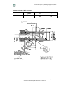


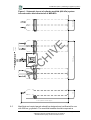


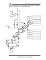
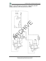


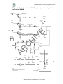


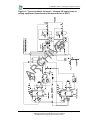


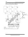


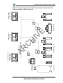


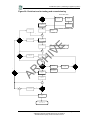


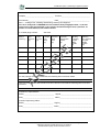
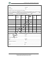


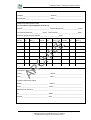


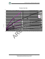


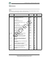


![potential power supply failure [PDF 123KB]](http://vs1.manualzilla.com/store/data/006020611_1-7b2a515ae5adf40e5465ac14994129f2-150x150.png)