1
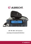
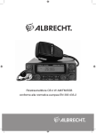
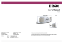
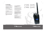
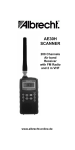
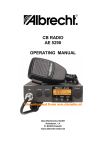
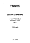
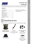
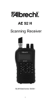
AE 485 S
10 meter Amateur Radio Transceiver
for AM / FM / SSB
according to EU standard EN 301 783 -2
1
Contents
Legal and General Information .....................................................................................................................................3
Preparation for Use.......................................................................................................................................................5
General Use Instructions ..............................................................................................................................................5
Connect to Power Supply .............................................................................................................................................5
Safety Precautions and Vehicle Installation .................................................................................................................5
Select Antenna - Vehicle Antenna...............................................................................................................................5
Operation as Base Station............................................................................................................................................6
Location of Controls AE 485 S (The picture is for the similar AE 5800 CB radio version)...........................................6
Controls and Switches ..................................................................................................................................................6
On/Off, Volume and Squelch Setting............................................................................................................................6
Mic Gain (3) ..................................................................................................................................................................6
RF Gain (4) ...................................................................................................................................................................7
Clarifier (11) ..................................................................................................................................................................7
LCD, S Meter and Power Meter ...................................................................................................................................7
Channel or Frequency Display .....................................................................................................................................7
Frequency Steps (channel knob)..................................................................................................................................8
Buttons AE 485 S (5-12)...............................................................................................................................................8
Select Mode ..................................................................................................................................................................8
USB and LSB................................................................................................................................................................8
Set Transmission Power...............................................................................................................................................9
How to Receive SSB? ..................................................................................................................................................9
Use Frequency Memory ...............................................................................................................................................9
Enter Frequency ...........................................................................................................................................................9
Recall saved Frequency ...............................................................................................................................................9
CALL Channel ..............................................................................................................................................................9
Scan Mode....................................................................................................................................................................9
Start and Stop Scanning...............................................................................................................................................9
Reverse Scanning Direction .........................................................................................................................................9
Last Channel Recall (LCR).........................................................................................................................................10
Noise Blanker .............................................................................................................................................................10
Simplex- and Repeater Operation ..............................................................................................................................10
Repeater settings........................................................................................................................................................10
Activate the Repeater Shift .........................................................................................................................................10
Change Shift Value.....................................................................................................................................................10
Sound Filter.................................................................................................................................................................10
Activate/Deactivate Key Tone.....................................................................................................................................10
Interesting Facts Relating to the Technical Data........................................................................................................10
Storage and Backup of Set Data ................................................................................................................................10
Ports for Additional External Devices .........................................................................................................................11
Reset to Default and Deleting All Memory..................................................................................................................11
Disposal and Recycling ..............................................................................................................................................11
European Warranty 2 Years from Purchase Date......................................................................................................12
Technical Data............................................................................................................................................................12
General .......................................................................................................................................................................12
Service Contact Address (in Germany) ......................................................................................................................13
2
Legal and General Information
The legal regulations in some countries demand a printout of our CE Declaration of Conformity in its original
wording (editorial status: March 2010). The latest regulations, announcements and other documentation for this
device are published in the service download area at www.hobbyradio.de or www.alan-albrecht.info. Please
observe the country-specific regulations when using this device and take the obligatory registration in individual
countries and possible operation restrictions serious!
As Amateur Radio, there are important restrictions for use of this radio. Most important is the following
The radio is allowed to be used only by licensed radio amateurs
•
It is not allowed to transmit on frequencies outside the allocated 10 m amateur band, even if the frequency
switching of the radio should allow it technically.
•
The band limitation depends on country specific amateur radio regulations. For use in Germany, there is
no band limitation requested for amateur radios.
•
In other countries except Germany it may be allowed only to use band limited equipment.
•
Even if you have an Amateur radio license, the license does not give you the right to use this transceiver
for any other purpose than amateur radio in the 10 m Band.
•
Persons, who do not have a valid amateur radio license, are not allowed to operate this radio.
•
The radio fulfills the technical requirements of European Amateur radio standard EN 301 783-2.
Among other parameters, this means, that the essential requirements for radiations in the spurious domain
are within limits. However, any combination with power amplifiers, permanently connected SWR meters or
automatic RF operated antenna switches may increase the radiated spurious values. The radio amateur is
responsible to keep his radiations within the amateur radio limits at any time. It cannot be excluded, that
the national authorities may impose restrictions of use in individual cases.
•
Please consider the minimum distances between antennas and persons in the near field of your antenna
installation (as base station) and observe the national requirements for site registration, where requested.
3
Declaration of Conformity
CE- Declaration of Conformity / Konformitätserklärung
We hereby declare that our product: / Wir erklären hiermit, dass unser Produkt
Amateur Radio Albrecht AE 485 S
satisfies all technical regulations applicable to the product within the scope of EU Council Directives, European Standards and
national frequency applications:/ alle technischen Anforderungen im Geltungsbereich der EU Richtlinien, europäischer Normen
und nationaler Frequenzanwendungen einhält:
73/23/EEC, 2004/108/ EG and 99/5/EC
EN 301 783-2 V 1.1.1
EN 301 489-1 V.1.8.1, EN 301 489-15 V1.2.1, EN 60 950-1 :2006
All essential radio test suites have been carried out. /
Alle für das Produkt vorgeschriebenen Funktestreihen wurden durchgeführt.
Alan Electronics GmbH
Daimlerstr.1 k
D- 63303 Dreieich
This declaration is issued under our sole responsibility. Basing on not harmonised frequency applications and international
amateur radio regulations, the use of this radio in Europe is restricted to holders of a valid amateur radio licence and is only
allowed for amateur radio traffic on the dedicated amateur radio frequencies. This radio is not allowed for any other application,
not by radio amateurs or any other persons.
Diese Erklärung wird unter unserer alleinigen Verantwortung abgegeben. Dieses Funkgerät darf wegen der nicht harmonisierten
Frequenzanwendungen und der internationalen Regelungen über den Amateurfunk in Europa grundsätzlich nur von Inhabern
einer gültigen Amateurfunklizenz benutzt werden. Dabei dürfen nur dem Amateurfunk zugewiesene Frequenzen im Rahmen des
Amateurfunks benutzt werden. Jegliche andere Verwendung des Geräts ist weder durch Funkamateure noch andere Personen
erlaubt.
Point of contact/Ansprechpartner:
Place and date of issue:
Dipl.-Phys. Wolfgang Schnorrenberg
Dreieich, 28. 3. 2010
(Signature)
Dipl.-Phys. Wolfgang Schnorrenberg
Alan Electronics GmbH
4
Preparation for Use
General Use Instructions
This AM-FM-SSB transceiver AE 485 S is a universal 10 m radio for 12VDC power supply. It an be connected to
powerful 12V batteries, such as rechargeable lead batteries, but also via a suitable 12V power adapter with at least
6A stabilized constant current to 230V mains power supply. Due to its SSB operation, demanding repeated finetuning and delicate operation, the radio is not intended for the use in vehicles when driving.
The radio is intended for intermittent operation with an average transmission time of approx. 10% of its duty cycle,
as it is typical for voice operation. This device is not intended for continuous transmission without regular reception
periods as cooling phases. Avoid subjecting your radio to high humidity, extremely high or low temperatures, dust
and direct sunlight. Only open the casing of your radio if you are knowledgeable in this regard, have the correct
tools and measuring devices.
The device comes with the international 10 m band range 28.000 MHz to 29.6 MHz with user selectable frequency
steps or channel steps similar to the common CB rules. AM, FM, USB and LSB can be selected.
Any extension of the frequency range und the use of other channels and modes than permitted in the individual
countries may lead to prosecution.
Connect to Power Supply
Connect your device with the supplied DC cable to a 12V network or a 12V power adapter. Voltage fluctuation
between 11V and 14V for power adapters and max. 15.6V, as in vehicles, campers or boats with rechargeable lead
battery, chargers or alternators, are permissible. Battery and/or power adapter must supply at least 6-8 Ampere
with good stabilization. Do not extend the power cord. In vehicles always try to connect directly to the battery
terminals. In this case you have best immunity against interferences from ignition and alternator and the most
stable supply voltage.
In case the fuse integrated in the DC cable blows, please check the possible cause first (commonly voltage
reversal and a flyback diode has reacted) and replace the fuse only with same type (10 Ampere, American glass
fuse), and never bypass with foil or similar measures!
Connect the red cable to the + terminal, and the black cable to the – terminal of the power source.
The minus terminal for this radio is on the casing, as usual for all modern vehicles. When installing in boats safety
measures against electrolytic and/or galvanic corrosion, such as insulated installation and galvanic insulation of the
antenna connections may be necessary due to the grounding of the casing.
Safety Precautions and Vehicle Installation
The device contains no components that must be accessible for the user during operation. Leave the opening of
the casing to experts. Do not open the casing before disconnecting from 12V power supply. For use in cars, trucks,
boats or RV vehicles mount your radio with the supplied screws and bracket in a suitable position. Ensure that no
risk of injuries for driver and passengers comes from the mounting position and avoid close proximity of air vents.
Do not use your radio when driving. The device is neither intended not approved for this kind of operation.
According to the Federal Motor Transport Authority the device is due to its risk potential only to be used in parked
vehicles.
Select Antenna - Vehicle Antenna
This radio is not to be used with common 10 m base or mobile, or even retuned CB radio antennas, such as a
magnetic foot antenna, balcony antennas, ground plane base station antenna or bult-in high efficiency car
antennas. For electromagnetic compatibility in combination with near electronic components a powerful vehicle
antenna with antenna base earthed via the chassis is to be used. When selecting the antenna position keep the
greatest possible distance to passengers and all vehicle electronics. Avoid the side of the mudguard as mounting
position which is nearer to passers-by on walkways. (this may be the left side in UK and the right side in continental
Europe). Ensure best grounding for antenna base, as this ensures that no HF reaches the interior of the vehicle via
sheath waves.
According to the latest EU directives vehicle manufacturers have the right to stipulate antenna positions and
maximum compatible transmission power for their vehicles. Please observe these guidelines, as you may
otherwise risk loosing the operating license for your vehicle. Ask your vehicle manufacturer for further information.
5
Have your vehicle manufacturer verify that he has no objections against the Amateur radio operation in connection
with the vehicle electronics!
Even though the effects of “electric smog” are controversial, you may not want to expose other persons, who may
think your hobby dangerous, to electromagnetic fields. In case you wear a pacemaker, please observe the greatest
possible distance to the antenna. If in doubt, obtain the manufacturer’s information with regard to recommended
safety distance.
It goes without saying that your antenna is to be optimized in standing wave ratio. The AE 485 S output stage
copes during operation with SWR of up to 1:2 at full capacity and short-term up to 1:3 (e.g. during adjustment).
Never press the transmission button without connected antenna!
The radio is equipped with a SO 239 socket (for PL connector) for antenna connection. For connection and cable
up to approx. 15 m RG-58/U cable is sufficient, otherwise we recommend RG-213/U or RG-8/U cable. Do not use
coax cable for satellite or TV, as these have 75 ohm and are not suitable for radio operation.
Operation as Base Station
Only use an external antenna for AE 485 S. Any kind of interior antenna creates such high HF fields in close
proximity that own electronic devices or devices of others are interfered with, even with sufficient EMC immunity
according to EU directive! For instance hum trouble from your own power adapter or via the microphone to the
transmitter, irradiation into VCR or hi-fi equipment and the like are well known. Especially in SSB mode, rather than
in FM mode, it can come to interferences with other devices due to the pulsating transmission signals.
Location of Controls AE 485 S (The picture is for the similar AE 5800 CB radio version)
14
1
2
3+4
5
6
7
8
9
10
11
12
13
Controls and Switches
On/Off, Volume and Squelch Setting
Turn the combined volume/on/off control knob (1) to turn the device on and off. With first use set the volume to a
medium level and turn the squelch button (14) fully counter-clockwise, until you can hear the background noise.
Now set squelch in such way that the background noise just disappears. In this position squelch opens even with
weak signals and is in its most sensitive position.
If setting squelch above this point clockwise, the signals have to be stronger to be put through.
Mic Gain (3)
This control knob is designed for dual function with the RF gain control. Use the upper control knob (3) to set the
sensitivity of the microphone. For the supplied hand microphone the control knob may be set to 2/3 or full
(clockwise). For other microphones the control knob serves individual setting. Optimum modulation is best set with
a control receiver or with an outstation.
6
RF Gain (4)
Use the RF Gain knob (lower, outer dial of the dual control knob) to set the amplification in the RF receiver. Turn
fully clockwise for the unit to have the highest amplification and sensitivity. This setting is optimal for most receiving
ratios. Turn the RF gain control knob back to mask unwanted long distance or interference signals, especially
when deliberately listening to near stations. In SSB mode with high field strength it may be necessary to adjust the
amplification with the RF gain control knob for optimum quality.
Clarifier (11)
This control knob serves the receiver fine-tuning and is only used in SSB mode if the distant partner station is not
quite on the same transmission frequency. In radio circles with several participants you frequently have to fine tune
individual stations with the clarifier for best comprehensibility.
LCD, S Meter and Power Meter
Your radio comes with a large backlit LCD for all settings, such as channel, frequency, status display and analog
values, such as received field strength (S meter) and transmission power. In this way you always have the most
important parameters in view. The S meter setting corresponds with the international short wave amateur standard:
100 µV EMC antenna voltage corresponds to S 9. The S meter uses a 5-stage bar display on the LCD. The
stronger you receive an outstation, the stronger is the deflection on the S meter.
For checking the S meter also works for transmissions as a power meter and gives you an approximate clue about
the output power. You will see that for FM you will always have the same transmission display, for AM the
deflection is generally less, and for SSB it varies with the rhythm of the speech.
Channel or Frequency Display
With first use the unit starts in FM mode and a frequency in the 29.300 MHz range is displayed. The unit starts in
frequency mode. (the pictures below show the similar operating CB radio AE 5800)
Channel mode
Frequency mode
The switching between the frequency mode and the channel mode works only when the 454 CH mode is activated.
This is possible for units sold in Germany (but not possible in all countries of sales!):
•
•
•
To activate the 454 channel mode press first FUNC (12). In the display FUNC will appear.
Now hold key „2“ (7) several seconds pressed. Now the radio switches to the 454 CH mode (where
allowed).
In this mode the bands A, B, C, D etc. appear. These are band segments with 40 channels each. You can
change the band segments by successive pressing on key 2 .
(please see the frequency-channel list at the end of the manual. Please note that the channel mode exceeds the
10 m band frequency limits. Radio amateurs are only allowed to use the frequency allocation of their license class.
This is the reason why we are not allowed to ship this radio with activated channel mode into some countries.
•
•
•
•
You can toggle your display to channel mode similar to CB radio devices.
First briefly press the FUNC button (12). The display shows FUNC.
Now press the 2 button (7).
In the channel mode, the unit switches in steps of 10 kHz and in a channel numbering like on CB radio
standard of international 10 kHz resolution, with some channels showing a 20 kHz step instead of 10 kHz
(for historical reasons).
7
•
•
You can tune the frequency via the CHANNEL knob (9) on the unit or with the UP/Down buttons on the
microphone.
Press FUNC followed by 2 to toggle between the display modes.
Frequency Steps (channel knob)
Per default the frequency steps are 10 kHz. You can change the step width by key STEP (5) to 1, 10 or 100 kHz
steps. After 1 x pressing STEP you will see the cursor appearing below the corresponding digit of the frequency
readout, depending how often you press the button. Now you can select the digit of Your choice with the channel
knob or up/down. Pressing FUNC (12) will switch back to 10 kHz default step system. The 10 kHz steps now will
start from the before shifted frequency!
Example: You have used STEP and the channel switch and reached 29.138 MHz. Now you press FUNC and use
the channel switch again. Your next frequency will be 29.148 MHz, 27.158 MHz and so on.
Buttons AE 485 S (5-12)
The buttons of your unit are multi-functional and change automatically – according to the mode – or in combination
with the FUNC button (12) manually. To avoid confusion you will find only the name of the corresponding function
in this user manual. For instance for pressing the MODE button you will find “MODE” and not the all names of all
functions for this button, such as “MODE/LOW/5”. Furthermore, all button functions, which are only possible in
connection with the FUNC button, are printed in blue.
Select Mode
Press the MODE button (8) to toggle between AM, FM, USB and LSB. The selected mode is displayed. The
abbreviations stand for:
AM
FM
USB
LSB
Amplitude modulation A3 with full carrier
Narrow band frequency modulation (max. 2.0 kHz range)
Single-sideband modulation, upper side band
Single-sideband modulation, lower side band
The different modes for Amateur radios are partly historical, as Amateur radio started with AM more than 50 years
ago. AM (amplitude modulation) mode corresponds with the technical operation of medium wave and short wave
broadcast und is, except for CB radio, currently used for aircraft radio. While speaking the transmission power is
adjusted rhythmically (technical term “modulated”). AM is traditionally the radio system used by truck drivers
worldwide for CB radio. The low background noise is advantageous if for instance in low interfering diesel trucks
squelch is left open during standby operation. A disadvantage is the lower communication range compared to FM
(because of higher allowed power in FM) or even SSB and the varying volume between near and far stations.
In FM mode the transmission power is always the same when speaking, thus hardly any interferences from other
units are to be expected in this mode. Instead the frequency of the unit varies during speaking and for this reason it
is called frequency modulation. Advantage is a greater range compared to AM and a constant volume of near and
far stations as well as a clear modulation sound. Some noise is a disadvantage and can be heard with weak or
missing signals. In FM mode it is basically not possible to leave squelch open in standby operation. FM is used on
the 10 m Band only for operation via repeaters.
SSB (Single-SideBand) marks the height in the development in long distance traffic voice transmission. SSB mode
avoids the disadvantage of low range of AM and concentrates all transmission power on a minimum frequency
width with speech pauses reducing the output to nearly zero. For reception a special circuit ensures that the
transmission of cut off “sidebands” and the “carrier” are again restored. This achieves an enormous increase in
range compared to AM and FM. Not only does the transmitter reach further, also the receiver is substantially more
sensitive through the halved bandwidth. All this has to be paid for with the disadvantage of a very fine tuning being
necessary for reception and that there is a higher risk of interferences of nearby devices during transmission. Due
to the necessary fine tuning of the receiver with the “Clarifier” (11) the use of SSB in moving vehicles is a problem
and can distract in an objectionable way from the traffic, similar to using a mobile phone. SSB is rather a mode for
base stations. This is also the reason, why today only experienced radio operators use SSB – you really have to
train and develop a sure instinct for the correct setting.
USB and LSB
In SSB mode a conventional channel is divided in two halves: the so-called upper sideband (USB) and the lower
sideband (LSB). Both can be used independently. Example: you transmit 28.500 MHz in USB. In reality you use
8
for speaking only the frequencies upward of 28.500 to approximately 28.503 MHz, while in LSB mode the
frequencies below 28.500 MHz to approximately 28.497 MHz are used. Both sidebands are mirror-inverted and
this is why receiver and transmitter must be set to the same sideband. Otherwise you only receive some
incomprehensible gibberish.
Set Transmission Power
Your unit comes with continuously variable transmission power. In normal state the control knob PWR (14) should
be set fully clockwise. In this setting you achieve max. 25 Watts in FM and SSB and about 7-8 Watt in AM. Turn
counter-clockwise to reduce power to approx. 100 mW. This should be done if you want to be heard only in the
absolute near proximity.
By the way: it also reduces the general electric smog level if the transmission power is set as low as just needed
for the radio link!
How to Receive SSB?
As receiving station of course you do not know in which sideband your outstation is currently transmitting. That the
outstation is transmitting in SSB mode is easily found out, because the “squawking noise” is very different from FM
or AM signals. First receive in USB. Carefully tune through the Clarifier. If you hear a “Mickey Mouse like” pitch
carefully fine-tune to a more comprehensible pitch. If this is not possible try the other sideband LSB.
You will need some experience until you clearly understand your first dialog partner in SSB mode. But surely you
will soon be rewarded by your first DX (= long distance traffic) connection.
Use Frequency Memory
Frequently used frequencies or channels can be saved and retrieved including the corresponding mode by
pressing MSAVE/MLOAD (10) in 5 station memories. The settings are not erased during temporary power failure,
as the unit works with low power backup technology.
Enter Frequency
Set the desired frequency. Press the buttons FUNC + MSAVE + station memory (1-5) in sequence to save the
frequency.
The display shows an “S” for “SAVE” after pressing FUNC + MSAVE.
Recall saved Frequency
Press MLOAD and the station memory (1-5) to access saved station memories (the display shows an “L” for “Load
memory” after pressing MLOAD).
CALL Channel
Station memory 2 is especially easy to access by briefly pressing 2 (CALL). As a conformation for this preference
channel the display flashes as long as the channel is selected. To leave the CALL channel briefly press 2 (CALL)
again. The default call frequency is 29.300 MHz. The last used channel is displayed again.
Scan Mode
Scanning allows you searching the band beginning with the last frequency or channel. In does not matter if the last
frequency was a station memory. After finding a signal in scan mode this channel is monitored for maximum 8
seconds, unless the signal disappears earlier. In this case scanning starts again until the next signal is detected.
Start and Stop Scanning
Press the SCAN (9) button; scanning starts. You can stop scanning by either pressing the PTT button or pressing
the SCAN button again.
Important: Scan mode uses the squelch setting as switching criteria. Set squelch first to the value for the scanner
to stop at a used channel. Scanning is not possible with open squelch: This state is detected by the CPU as a used
channel and it switches in 8-seconds cycle to the next channel.
Reverse Scanning Direction
You can change the scanning direction from up to down or vice versa at any time. Briefly turn the channel selector
in the desired direction or use the UP and DOWN buttons on the microphone.
9
Last Channel Recall (LCR)
If you were scanning or listening a lot to other frequencies you may want to return to your last transmission channel
by pressing a single button? Press the LCR (6) button to return to the last channel you used for transmission for
more than 3 seconds.
Noise Blanker
A noise blanker is a circuit to fade out or limit temporarily pulsating interferences. As the 10 m band is especially
effected by noise from electrical appliances and vehicles your unit is equipped with a corresponding function to be
engaged in AM and SSB modes.
The noise blanker is activated/deactivated by pressing FUNC and NB (5).
Simplex- and Repeater Operation
With the default settings you can start to communicate point-to-point on simpex channels. In the years of high sunspot activities you can reach communication distances of several 1000 kilometers. A good indicator for long
distance conditions are the repeater stations in Europe and USA. Most of the repeaters can be found in the upper
band segment just below 29.670 MHz.
Repeater settings
You can reach repeaters in Europe and – under good propagation conditions as well in USA. For repeater
operation it is necessary to shift your transmitting frequency to the uplink frequency of the repeater, while you listen
on the downlink frequency. For example you hear a repeater on 29.670 MHz. Then the suitable transmitting
frequency for this repeater is 100 kHz lower at 29.570 MHz in this example.
Activate the Repeater Shift
Press first FUNC and then SHIFT (9) in sequence. +SHIFT will appear in the display. Press both buttons once
more, then you obtain –SHIFT.
Factory default value is 600 kHz (Far East). In Europe we use 100 kHz, so you should change the setting from 600
kHz to 100 kHz.
Change Shift Value
The frequency shift can be varied between 10 and 999 kHz. Use again the sequence of FUNC and SHIFT, but then
hold the SHIFT-key more than 3 seconds pressed, until the display shows 600.
Now you can use the rotary channel knob or the UP / DOWN- buttons at the microphone to adjust the shift value
to the European / USA standard value 100 kHz.
Confirm the setting be pressing the PTT button or the FUNC button.
Sound Filter
The receiver comes with a switchable sound filter, what is especially useful for noisy signals, as it attenuates the
aggressive high sounds, making the sound easier to listen to. Deactivate this filter by pressing FUNC and LOW (8).
Activate/Deactivate Key Tone
Turn the unit on while pressing the transmission button (PTT on microphone). In this way you toggle between
activation and deactivation.
Interesting Facts Relating to the Technical Data
Storage and Backup of Set Data
The radio is no longer equipped with a lithium battery, but uses the low power backup technology. For this reason
data are only erased after a long time.
10
Ports for Additional External Devices
Microphone Jack (2)
6-pole, Jap. standard, suitable for screwable electret or other microphones with approx. 600 ohm to 1 kOhm
impedance.
PIN 1
PIN 2
PIN 3
PIN 4
PIN 5
PIN 6
Microphone NF
PTT-RX (not used for this unit) – also for NF extraction packet radio
PTT-TX contact
UP/DOWN button
Ground, shielding
Power supply for electret microphone (or other accessories)
Important: Wiring according to “Albrecht” Standard, widespread for CB radios. Please observe when connecting
other microphones! In case you want to connect a different microphone: Only use microphones with electret
capsules. Additional devices, such as modems, etc. are only permitted in FM mode. Please observe the
regulations in the individual countries.
Speaker Jack (Rear)
3.5 mm mono jack, suitable for 4-8 ohm speakers with minimum 2-4 Watts. The internal speaker is automatically
muted when connecting an external speaker.
Maintenance and Programming
The following references are exclusively for expert service staff. Program settings are only permitted for authorized
users and for commercial export in countries allowing the corresponding versions.
No responsibility for damages and consequential damage caused by incompetent or not expressly by Albrecht
explained programming steps and other interference. The end user warranty generally expires with opening the
casing. Only use Albrecht specialized dealers for modifications during the warranty period!
Reset to Default and Deleting All Memory
A general reset to factory settings is possible by disconnecting from power supply and briefly pressing the reset
button on the separate small internal SUB Board after removing the speaker cover (visible after removing the
cover). Perform this reset when experiencing malfunctions. There are inevitable external interferences, which may
block the processor or lead to certain functions being not or not correct performed. The interferences can be
caused by electric storms, overvoltage, to great HF irradiation and the like and are generally easily fixed by reset.
However, reset also deletes all station memories.
For Amateur radio the factory jumper setting CON1 on the internal Sub Board is permitted for all countries
(28.000 to 29.700 MHz).
Other settings are permitted for amateur radio, but maybe restricted in some countries. The user needs a valid
amateur radio license. Even amateur radio operators are only allowed to use frequencies allocated for amateur
radio, even if a device can be programmed for further frequency ranges. You find the permitted jumper setting for
amateur radio operators at http://www.hobbyradio.de/Amateurfunk under AE 485S. Please note that our
Declaration of Conformity expires with modifications.
Disposal and Recycling
This radio was manufactured with low emission according to the new European RoHS and
WEEE directives. For disposal please note that electrical and electronic devices can no longer
be disposed of with the household waste; they must be disposed of at municipal collection
points. The return of used appliances is free, as the manufacturers cover the disposal costs. By
returning the device to a municipal collection point you contribute to the recycling of valuable
resources.
11
European Warranty 2 Years from Purchase Date
The vendor of this device grants an implied warranty of two years from the date of purchase. This warranty
includes all malfunctions caused by defective components of malfunctioning within the warranty period, but not
malfunctions due to normal use, such as scratches on display or casing, defective casing, broken antenna,
consumed light bulbs, damaged microphone cables and defects due to external forces, such as corrosion,
overvoltage due to improper external power supply or the use of unsuitable accessories. Furthermore,
malfunctions due to improper use, such as a defective transmission output stage caused by a mismatched antenna
or connection of illegal amplifiers, are excluded from the warranty.
In case of warranty claims contact your dealer directly. The dealer will either repair or exchange the device, or he
will give you the address of a specialized service center for the device.
If in coubt, please contact our hotline. In case you want to send your device in for repairs, please remember to
include your proof of purchase and describe the malfunction as clearly as possible.
Technical Data
General
Frequency range (jumper setting 2)
Frequency stability
Transmission type
Admissible operating voltage range
Fuse
28.000 MHz – 29.700 MHz
+/-400 Hz
A3E, F3E, J3E
10.8 - 15.6V DC
10 A
Transmitter
Transmission power
(other power levels for different
countries available on request)
Harmonic suppression
Microphone sensitivity
Supplied microphone:
Dynamic control
Power consumption transmission
AM
FM
SSB
microphone ALC
ca. 7-8 Watt
max. 25 Watts
max. 25 Watts PEP
min. –60 dBc
4 mV / 1 kOhm
Electret with integrated pre-amplifier
50 dB
max. 2.5 (AM)
max. 3.0- 6 A depending on power setting (FM,
SSB)
Receiver
Receiver sensitivity
Clarifier control range
Audio output power
0.5 µV EMK FM/SSB
0.9 µV EMK AM
60 dB FM/AM
70 dB SSB
+/- 1 kHz
2.5 Watts at 8 ohms
Dimensions incl. knobs/jacks
Weight
24.5 x 15.5 x 5.3 cm
1.3 kg
Receiver adjacent channel selection
for 12 dB SINAD
12
Service Contact Address (in Germany)
You find technical documentation and the latest information regarding the regulation in individual EU countries in
the service pages of the Albrecht and Alan websites and directly on the download server www.hobbyradio.de
Alan Electronics GmbH
or
http://www.albrecht-online.de
Daimlerstr. 1 K
Dovenkamp 11
D-63303 Dreieich
D-22952 Lütjensee
http://www.alan-electronics.de
Service enquiries:
Hotline
[email protected]
01805 - 012204 (0,14 Euro/minute from German landlines, mobile may be up to
0.42 Euro)
Important: Customers in Germany should contact the Hotline before returning any radio, because only our service
address can give you the nearest and best service partner address for the most efficient repair service.
Customers in other countries: please contact the local distributor, where you have bought the radio
© Alan Electronics GmbH 2010
It is prohibited to copy or reproduce this documentation full or in parts for commercial use without prior written
permission of Alan Electronics GmbH.
13
AE 485 S
Conversion Board / Programmierplatine
MODE
CON1
CON2
CON3
CON4
REMARKS / Bemerkungen
Only/ Nur 10m
yes/ ja
-
-
-
10m + 454 CH
-
yes/ ja
-
-
Step FUNC enable /ein
Amateurband-Start/ step FUNC enable
(ein)
-
-
yes/ ja
-
Step FUNC enable/ ein
-
-
-
yes / ja
Step FUNC disable/ aus
Only/ Nur 454
CH
Only/ Nur 40 CH
REMARKS / Bemerkungen:
Black / schwarz
Some countries may only allow CON 1 jumper (restricted to 10 m Amateur Band)
Red / rot:
Default setting AE 485 S for Amateur Radio in Germany/
entspricht Lieferzustand AE 485 S in Deutschland
Green / grün:
Setting for CB 40 channels only- not allowed for AE 485 S
Blue/blau
nur 454 CH Mode / nur 454 Kanalmode
Yes/Ja:
open / offen (Brücke nicht vorhanden bzw. entfernt)
install mini jumper / Mini Steckbrücke eingesteckt
Positions CON1 - CON3 only for licensed amateur radio operators allowed / CON 1 bis CON 3 nur
für lizenzierte Funkamateure im Rahmen ihrer Lizenzbestimmungen erlaubt-
Mini Jumper
Steckbrücke
Reset-Taste
Die Drahtfarben können – je nach Lieferung abweichen und sind nicht maßgeblich
©Alan Electronics 2006
Channel number
1
2
3
3A
4
5
6
7
7A
8
9
10
11
11A
12
13
14
15
15A
16
17
18
19
19A
20
21
22
23
24
25
26
27
28
29
30
31
32
33
34
35
36
37
38
39
40
41
42
43
44
Band A
25.165
25.175
25.185
25.195
25.205
25.215
25. 225
25. 235
25.245
25. 255
25. 265
25.275
25.285
25.295
25.305
25.315
25.325
25.335
25.345
25.355
25.365
25.375
25.385
25.395
25.405
25.415
25.425
25.455
25.435
25.445
25.465
25.475
25.485
25.495
25.505
25.515
25.525
25.535
25.545
25.555
25.565
25.575
25.585
25.595
25.605
B
25.615
25.625
25.635
25.645
25.655
25.665
25.675
25.685
25.695
25.705
25.715
25.725
25.735
25.745
25.755
25.765
25.775
25.785
25.795
25.805
25.815
25.825
25.835
25.845
25.855
25.865
25.875
25.905
25.885
25.895
25.915
25.925
25.935
25.945
25.955
25.965
25.975
25.985
25.995
26.005
26.015
26.025
26.035
26.045
26.055
C
26.065
26.075
26.085
26.095
26.105
26.115
26.125
26.135
26.145
26.155
26.165
26.175
26.185
26.195
26.205
26.215
26.225
26.235
26.245
26.255
26.265
26.275
26.285
26.295
26.305
26.315
26.325
26.355
26.335
26.345
26.365
26.375
26.385
26.395
26.405
26.415
26.425
26.435
26.445
26.455
26.465
26.475
26.485
26.495
26.505
D
26.515
26.525
26.535
26.545
26.555
26.565
26.575
26.585
26.595
26.605
26.615
26.625
26.635
26.645
26.655
26.665
26.675
26.685
26.695
26.705
26.715
26.725
26.735
26.745
26.755
26.765
26.775
26.805
26.785
26.795
26.815
26.825
26.835
26.845
26.855
26.865
26.875
26.885
26.895
26.905
26.915
26.925
26.935
26.945
26.955
E
26.965
26.975
26.985
26.995
27.005
27.015
27.025
27.035
27.045
27.055
27.065
27.075
27.085
27.095
27.105
27.115
27.125
27.135
27.145
27.155
27.165
27.175
27.185
27.195
27.205
27.215
27.225
27.255
27.235
27.245
27.265
27.275
27.285
27.295
27.305
27.315
27.325
27.335
27.345
27.355
27.365
27.375
27.385
27.395
27.405
F
27.415
27.425
27.435
27.445
27.455
27.465
27.475
27.485
27.495
27.505
27.515
27.525
27.535
27.545
27.555
27.565
27.575
27.585
27.595
27.605
27.615
27.625
27.635
27.645
27.655
27.665
27.675
27.705
27.685
27.695
27.715
27.725
27.735
27.745
27.755
27.765
27.775
27.785
27.795
27.805
27.815
27.825
27.835
27.845
27.855
G
27.865
27.875
27.885
27.895
27.905
27.915
27.925
27.935
27.945
27.955
27.965
27.975
27.985
27.995
28.005
28.015
28.025
28.035
28.045
28.055
28.065
28.075
28.085
28.095
28.105
28.115
28.125
28.155
28.135
28.145
28.165
28.175
28.185
28.195
28.205
28.215
28.225
28.235
28.245
28.255
28.265
28.275
28.285
28.295
28.305
Frequeny table for AE 497 S, AE 485 S and AE 201 S in activated channel mode
H
28.315
28.325
28.335
28.345
28.355
28.365
28.375
28.385
28.395
28.405
28.415
28.425
28.435
28.445
28.455
28.465
28.475
28.485
28.495
28.505
28.515
28.525
28.535
28.545
28.555
28.565
28.575
28.605
28.585
28.595
28.615
28.625
28.635
28.645
28.655
28.665
28.675
28.685
28.695
28.705
28.715
28.725
28.735
28.745
28.755
I
28.765
28.775
28.785
28.795
28.805
28.815
28.825
28.835
28.845
28.855
28.865
28.875
28.885
28.895
28.905
28.915
28.925
28.935
28.945
28.955
28.965
28.975
28.985
28.995
29.005
29.015
29.025
29.055
29.035
29.045
29.065
29.075
29.085
29.095
29.105
29.115
29.125
29.135
29.145
29.155
29.165
29.175
29.185
29.195
29.205
J
29.215
29.225
29.235
29.245
29.255
29.265
29.275
29.285
29.295
29.305
29.315
29.325
29.335
29.345
29.355
29.365
29.375
29.385
29.395
29.405
29.415
29.425
29.435
29.445
29.455
29.465
29.475
29.505
29.485
29.495
29.515
29.525
29.535
29.545
29.555
29.565
29.575
29.585
29.595
29.605
29.615
29.625
29.635
29.645
29.655
29.665
29.675
29.685
29.695