1
Precision Measurement Engineering, Inc. • www.pme.com
RS232/RS485 T-CHAIN User’s Manual
2010
Warranty
1-YEAR LIMITED WARRANTY ON T-CHAIN HARDWARE
Precision Measurement Engineering, Inc. (PME) warrant that the T-Chain shall
be free of defects in workmanship and materials, under normal use, for a period
of one year from the date of shipment. This warranty is made only to the original
purchaser. In the event a LakeESP covered by this warranty fails to operate
according to our published specifications, return it freight pre-paid to PME or an
authorized Service Provider. PME will repair the unit at no charge to the
customer, and bear the cost of return shipment. Carefully pack all components,
as the customer is responsible for any freight damage.
This warranty does not apply to services or consumable/ expendable items (such
as batteries, fuses and ropes) required for general maintenance. Equipment
manufactured by other companies (such as meteorology sensors, solar panels,
etc) are warranted only to the limit of the warranties provided by their original
manufacturer.
PME makes no warranty, either expressed or implied, that the sensors will be
operable after they are exposed to adverse environmental conditions, such as
bio-fouling, oil fouling, freezing temperatures or others.
This warranty is void if, in our opinion, the T-Chain has been damaged by
accident, mishandled, altered, or repaired by the customer, where such treatment
has affected its performance or reliability. In the event of such treatment by the
customer, costs for repairs plus two-way freight costs (no COD shipments will be
accepted) will be borne by the customer. In such cases, an estimate will be
submitted for approval before repair work is started. Items found to be defective
should be returned to PME carefully packed, as the customer will be responsible
for freight damage.
Incidental or consequential damages or costs incurred as a result of the product
malfunction are not the responsibility of PME.
For all warranty or non-warranty returns please obtain, complete, and submit a
RMA to PME. This RMA form may be obtained at
http://www.pme.com/HTML%20Docs/RMAform.html.
After submission of this from PME will respond with a RMA number. Please
place this number on all shipments and related communications.
Revision History
Date
10-JUN-2010
15-SEP-2010
22-AUG-2011
08-NOV-2013
Revision Description
Initial document
Corrected Hyperterminal setup Hardware to none flow control
Added information about RS485
Added PAR bracket and CHLA sensor. Added units.
CONTENTS
1.
Introduction to the T-Chain
5
2.
Quick Test
8
3.
Sensors
12
3.1
3.2
3.3
3.4
3.5
3.6
Temperature
Dissolved Oxygen
Depth
PH
PAR
Conductivity
4.
Connections & Communication
16
5.
Electrical Requirements
19
Deployment
20
6.
6.1
6.2
6.3
6.4
6.5
6.6
6.7
7.
Rope, Shackles, Thimbles
Float
Chain, Anchors
Attachment to T-Chain
Retrieval Rope
System Weight
Other Moorings
Maintenance
24
Appendix 1: Re-Programming
25
Appendix 2: Connecting to a Campbell Scientific Logger
26
1. Introduction to the T-Chain
The RS232/RS485 T-Chain is a single-cable string consisting of a small
microprocessor and sensors of various types. This instrument can produce both
RS232 and RS485 output. RS232 is bi-directional and can be directly connected
to a local PC COM port or other similar platform. Unless the user must operate
the T-Chain with over 15 meters of cable between the host computer and the TChain, RS232 communication protocol is recommended. The RS485 output can
travel up to 1000 meters if cabled via suitable cable but must be connected to a
suitable RS485 receiver (not provided by PME).
Most of this document reflects the use of RS232.
RS-232 T-Chains are normally programmed to output a string of measurements
in response to a carriage return sent by the host computer on the RS232
communication. This allows the host computer to synchronize T-Chain output.
RS-485 T-Chans have only output connections for RS485. In this case no
character can be received from the host computer. RS485 T-Chains are
programmed to simply emit the string of measurements repeatedly as long as
power is supplied. The host computer will have to implement a more complex
method of synchronization.
The T-Chain is completely waterproof and is terminated in an 8-pin underwater
connector. This connector is waterproof but not underwater mate-able.
The T-Chain begins with the underwater connector and continues via cable to a
small microprocessor and thereafter to the various sensors. T-Chains are always
custom built to customer specifications. Customers must specify the types and
positions of the sensors they require. Temperature sensors are directly molded
onto the cable. They can not be removed except by cutting and their positions
can not be changed. Other sensors are however fitted to the T-Chain via short
lengths of spur cable that make “Y” connections to the main cable. These
sensors can be removed and, if sufficient spur cable length is available, moved to
different locations along the main cable.
T-Chains are designed to be secured by cable ties to some other support.
T-Chains are supplied with a wired bulkhead connector. This assembly allows
quick connection to a PC COM port for initial tests of the T-Chain. In some cases
such as connection to a Campbell data logger within a Campbell enclosure, this
wired bulkhead connector can be used directly. In general the customer will,
after testing, disassemble the bulkhead wiring and install whatever is necessary
for the specific application.
Sensors are connected to the T-Chain in three ways:
•
•
•
Molded onto the T-Chain at permanent locations
‘Y’ onto the T-Chain
Connected at the end of the T-Chain
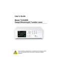
Temperature sensors are the only permanently molded sensors on the T-Chain.
The following picture shows a temperature sensor.
There are several other sensors that ‘Y’ onto the T-Chain. In general the sensors
are as shown in the following picture.
The picture shows the main cable that extends from far left to far right, a molded
temperature sensor at the right, a ‘Y’ connection at left, and a sensor (in this case
dissolved oxygen) towards the middle. The picture shows a common installation
of a sensor. However the cable from the ‘Y’ point to the sensor can be made
longer. In this case the sensor ca be re-positioned along the main cable.
Depth (Pressure) Sensors can be positioned along the cable but often they are
placed at the very bottom of the T-Chain. Depth Sensors are the only sensors
that are designed to be placed at the end of the cable.
The TChain emits a string of numbers that are separated by spaces. The
sequence of these numbers is established by the sequence that sensors are
connected to the T-Chain. An entire scan of all sensors on the T-Chain is
emitted on a single line, with following lines describing new scans of the T-Chain
sensor. The units of measure are described below with each sensor.
0
RS-232 Quick Test
The T-Chain is supplied with a wired bulkhead connector. This assembly is
designed to allow the RS-232 T-Chain to be quickly connected to a Windows
computer for testing. There is a 9-pin D connector that will plug directly into a
Windows COM port. There are also a red and black wire that receive power.
The Windows computer must have a COM port (serial port) and be running a
suitable terminal program to view the T-Chain RS232 output.
On Windows 2000 and XP the terminal program Hyperterminal may be found
under start\Accessories\Communications\Hyperterminal. For later Windows
operating systems Hyperterminal can be purchased from
http://www.hilgraeve.com/hyperterminal/
An alternate terminal program can be obtained free at
http://realterm.sourceforge.net/
In addition to a communications program, the Windows computer must have
serial COM port. Most modern laptops lack this port. A USB to serial adapter,
not supplied by PME, can be purchased for a small cost. In general these must
be physically plugged into the computer USB port and the software properly
installed prior to using Hyperterminal or another communications program.
Follow the manufacturer’s installation instructions.
The T-Chain communicates via a RS232 (+/- 5 V protocol) at 9600 Baud, 8 bits,
no parity, 1 stop bit. Hyperterminal must be set up for T-Chain communication.
Run Hyperterminal, select File\New Connection. A Connection Description
dialog box will appear.
In the Connection Description dialog window enter LakeESP in the Name box,
then press OK.
A Connect To dialog window will appear. Select the correct COM number for the
laptop (usually COM 1) or the USB adapter (could be COM 3 or COM 4 or other)
from the Connect using drop down box. Press OK. A Port Settings dialog box
will appear.
In the Port Settings dialog box select 9600 in the Bits per second drop down box,
8 in the Data bits drop down box, None in the Parity drop down box, 1 in the Stop
bits drop down box and None in the Flow control drop down box. Press OK.
Select File\Save. This will save your connection so that it can be reloaded at a
future time.
Plug the T-Chain 9 pin connector into the COM port connector. Supply between
9 and 12 Volts to the red and black power wires from the T-Chain bulkhead
connector assembly. Connect (+) to the red wire, (-) to the black wire.
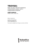
Upon connection the T-Chain should print a banner. Thereafter it will print a
string of measurements in response to the Enter key press on the computer’s
keyboard. The screen shot below is an example of what will be presented. The
exact display will depend upon the number and type of sensors on the T-Chain
If this response does not occur, check software installation and setup, and check
electrical connections. If these are all correct, contact PME.
0
Sensors
Sensor
Unit of
Measure
Range
Initial Accuracy
Stability
Temperature
degree C
-2 to 36
+/- 0.010
Dissolved
Oxygen
Depth
umol/l
0 to 800
Meters @
1gm/cc
pH
PAR
Conductivity
pH units
umol/(s *
m^2)
uS/cm
0 to 40
0 to 90
0 to 190
4 to 12
0 to 2500
+/- 10% or 10 umol/l
whichever is greater
slope: 1% FS
offset: 5% FS
approx +/- 0.030
deg C/year
TBD
CHLA
ug/l
+/- 1%/year
TBD
+/- 5%
+/- 2%/year
Selectable
up to
200,000
10%
TBD
0–5
0 – 50
0 – 500
Not calibrated
TBD
Time
Respon
se
<5
seconds
TBD
<5
seconds
TBD
<1
second
<5
seconds
<5
seconds
Attach
ment
molded
‘Y’
end of
TChain
‘Y’
‘Y’
‘Y’
‘Y’
Temperature
Temperature sensors are molded onto the T-Chain. They have available
response over the –2 to 36 degree C range. However they are normally
calibrated only over 0.5 to 36 degrees C. Special arrangements must be made
with PME when the T-Chain is ordered if the sensor is to be operated below 0.5
degrees C .
This sensor features rapid time response since the actual sensing element, a
thermistor, extends outside the potting material. This thermistor is enclosed in a
thin walled inconel tube. This is the silver tube in the cavity in the above picture.
This sensor has a digital output with service electronics potted at each node.
Under normal use this sensor will require no cleaning.
PME calibrates this sensor. The TChain emits temperature in degrees Celsius
units.
Dissolved Oxygen
The Dissolved Oxygen sensor is an optode that measures lifetime-based
luminescence quenching of fluorescence of a thin membrane. DO sensors are ‘Y’
connected to the T-Chain and can be removed for calibration or cleaning.
This sensor will require cleaning. The frequency of cleaning will depend upon
the amount of algae growth or other fouling. The typical cleaning interval in
surface layers of fresh water lakes is 1 month with longer intervals if the sensor is
deployed below the photic zone.
PME calibrates this sensor. The TChain emits dissolved oxygen in ug/l units.
Depth
The depth sensor is typically connected at the lower end of the T-Chain. There
are 3 ranges available, 5, 10, and 20 bar full scale. This sensor is an absolute
pressure sensor that produces depth by converting pressure into depth units
using
P = rho * g * h
P = measured pressure in Pascal (1 bar = 100000 Pascal)
rho = density of pure water at 4 deg C (1000 Kg/m^3)
g = standard accelleration of Earth’s gravity (9.80665 m/sec^2)
h = the depth in meters
Since the depth sensor is an absolute device it senses atmospheric pressure as
well as the pressure of the water column. Normally the T-Chain output is as
shown above and it is left to the user to adjust the value produced for local
atmospheric pressure, the actual average density of the water column, and to
adjust for variation in barometric pressure if desired. PME calibrates this sensor.
In actual use the deployment distance of the pressure transducer will be
somewhat uncertain and will depend upon things such as the depth that the
system anchor sinks into the sediment. The normal procedure will be to deploy
the sensor, measure the depth, adjust the sensor output by water column
density, and then add a constant number to give the correct initial depth.
PME calibrates this sensor. The TChain emits depth in meters of water
assuming 1 gm/cm^3 density units.
pH
The pH sensor is a SensorEx S222CD sensor which PME mounts, digitizes, and
connects into the T-Chain. The S222CD is a sealed double junction pH sensor.
The sensor is inexpensive and can be replaced in PME’s mounting, saving the
cost of replacing the mounting. PME performs the calibration of this sensor
using 3 standard solutions.
PAR
The PAR (Photosynthetically Active Radiation) sensor is a Li-Cor LI-192 sensor,
which PME mounts, digitizes, and connects into the T-Chain. This sensor must
be dismounted prior to return to Li-Cor for calibration. PME does not perform
calibration of this sensor, but implements the calibration supplied by LiCor.
The T-Chain is supplied with the PAR sensor connected and operational.
However the sensor must be attached to the T-Chain by the customer since the
attachment bracket is too large to be conveniently shipped. The customer will
provide PVC cement for this purpose. The customer must glue the pipe supplied
by PME as shown in the picture below. The sensor bracket is then attached to
the T-Chain by threading cable ties through the holes in the bracket and securing
them to the T-Chain cable.
The TChain emits PAR in umol/(s m^2) units.
Conductivity
The conductivity sensor is a electrode-less sensor. The range of this sensor is
selectable. The sensor is useful in salt water situations such as estuaries where
location of the transition zone is desired. The sensor lacks sensitivity for normal
fresh water lake use but has sufficient range for sea water and hyper-saline
lakes. The range of the sensor should be provided to PME at the time the TChain is ordered.
PME calibrates this sensor. The TChain emits conductivity in uS/cm.
CHL-A
The CHL-A sensor is a Turner Designs Cyclops 7 optical sensor that has been
adapted to PME’s T-Chain. This sensor has 3 ranges. A range must be selected
prior to installing on the T-Chain. Sensor range can not be changed thereafter
without disassembling the sensor.
CHL-A sensors are not calibrated by PME. However the T-Chain does emit the
units of ug/l. These are based upon the sensor range and are only approximate.
More accurate calibration must be done by the customer via a correlation of TChain output and concurrent sampling of the nearby water.
This optical sensor flows light into the nearby water and measures emissions.
The measurement volume is quite near the surface of the sensor, but there are
slight measurement errors from reflections in the far-field. Attempt to mount this
sensor with any reflecting structures not in its field of view.
This sensor is sensitive to fouling and should be cleaned by wiping gently by
hand as often as local conditions require.
This sensor is not calibrated. The TChain emits CHL-A in ug/l units.
4. Connections & Communication
The table below shows the pin-out of the PME T-Chain underwater connector
and bulkhead connector. The T-Chain is DCE.
RS-232 T-Chain and RS-485 T-Chain
Circuit Function
Power and RS232 ground
RS232 RXD (T-Chain receive from host)
RS232 TXD (T-Chain transmit to host)
RS485 YD(+)
RS485 ZD (-)
Power to T-Chain
(not used)
(not used)
T-Chain Connector/
Bulkhead Connector Pin #
1
2
3
4
5
6
7
8
Bulkhead Wiring Harness
Connection (P/N6738)
DB-9 pin 1 & Black wire
DB-9 pin 3
DB-9 pin 2
(not connected)*
(not conected)*
Red wire
(not connected)
(not connected)
*The customer must add appropriate wiring for RS-485 connection.
The bulkhead connector has numbers molded next to each pin. The T-Chain
connector is the mirror image and has pin numbers as shown in the following
sketch.
The communication parameters are
Parameter
Baud rate
# Bits
# Parity Bits
# Stop Bits
Value
9600
8
None
1
The RS-232 T-Chain is Data Communication Equipment and obeys the RS232
signaling voltage protocol by supplying +/- 5 Volts. The T-Chain can both send
and receive. Data transmission distance is greater than 3 meters using this
protocol. The RS-485 T-Chain obeys RS-485 protocol.
The T-Chain sends a banner each time the power is turned on. RS-323 TChains thereafter wait for a carriage return character to be sent from the
connected equipment. Upon receipt of this character the T-Chain responds with
an ASCII string of numbers and spaces terminated by carriage return and line
feed characters. RS-485 T-Chains simply emit measurement strings while
power is applied. An example is shown below.
The ASCII string displays the output of each sensor on the T-Chain in the order
that the sensor is connected along the chain. ‘Y’ connected sensors are
presented at the location given by the ‘Y’ connection and not at the actual
location of the sensor. Only numeric output is presented. The units are those
that are appropriate for the specific sensor.
Numeric output is made according to the C-language statement
printf(" %10.3f",((float)TNode[j]))
which produces floating point numbers in 10 character wide columns.
Connected equipment can synchronize to the RS-232 T-Chain output by the use
of the carriage return which is sent to the T-Chain. Connected software will first
empty it’s input buffer, then send the carriage return character, then examine the
data being returned from the T-Chain until a carriage return followed by a line
feed character are received. Connected software will then parse the buffer
based upon the space characters or based upon column numbering into substrings of single numbers and convert these ASCII representations into float or
double types for storage within the connected equipment.
Connected equipment must synchronize to RS-485 T-Chain output by software
examination of the character string being received from the T-Chain. Software
will empty it’s input buffer. It will then receive characters until a carriage return
followed by a line feed are received. Characters arriving thereafter will be placed
into the input buffer until the next carriage return followed by a line feed character
are received. Connected software will then parse the buffer based upon the
space characters or based upon column numbering into sub-strings of single
numbers and convert these ASCII representations into float or double types for
storage within the connected equipment.
5. Electrical Requirements
The T-Chain requires no less than 9 VDC and no greater than 20 VDC. Input
voltage should not contain substantial high frequency variation.
The measurement of temperature within the T-Chain is done using thermistors
shielded within inconel tubes. These tubes are not connected to the electric
ground within the T-Chain for corrosion reasons. These tubes therefore take on
the electrical potential of the surrounding water. There is a very slight capacitive
coupling between the tubes and thermistors. It is important therfore that the
electrical potential of the surrounding water be maintained the same as the
electrical potential on the T-Chain ground. T-Chains without pressure
transducers have a ground contact located at the end of the chain. This is
normally sufficient but the connected equipment must also implement good
grounding to the water.
T-Chains consume electrical current from the connected power supply. The
amount of current does not depend on the connected voltage to a significant
degree. It does however depend strong upon the number and type of sensors
connected. The following table and notes are intended to give an approximation
of the current demand, which should be computed as the sum based on the
sensors. The actual demand should be measured when the T-Chain is received.
Some sensors demand a continuous current. Others have substantially high
demands but only for brief periods following receipt of a carriage return character
by the T-Chain. Connected power supplies must be able to supply peak current
demand. Normally this is not a problem for battery operated devices, but if there
are long wires between the T-Chain and the battery, their inductance may limit
the peak currents. Connected equipment must be designed to supply peak
current demands.
The table below gives sensor voltage and current requirements. Idle current is
consumed at all times besides measurement time. Measurement current is
consumed at measurement time.
SENSOR
Input Voltage
(Volt)
Idle Current
(mA)
RS232 Computer
temperature
oxygen
depth
pH
PAR
Conductivity
9 to 20
9 to 20
9 to 20
9 to 20
9 to 20
9 to 20
9 to 20
30
0.3
1.5
TBD
TBD
TBD
2
Measurement
Current
(mA)
n/a
0.5
30
TBD
TBD
TBD
30
Measurement
Time
(second)
always on
0.4
0.04
0.4
0.4
0.4
0.8
6. Deployment
Deployment of the T-Chain is the customer’s responsibility. Deployment
arrangements should be designed so that the T-Chain never is tensioned.
It is difficult to anticipate all the possible deployments that customers might use.
However one simple example depolyment is a bottom anchor with a sub-surface
float. This example will be discussed below to point out common problems and
solutions.
The table below shows a bill of materials for a typical sub-surface buoy mooring.
These are discussed subsequently.
Qty Used
55
5
1
1.5 meter
40
3
1
2
Description
tchain rope,12-strand polyester, 3/8"x600ft (182m)
thimble, 3/8", 316ss, heavy duty (for tchain rope)
Float,subsurface,45#(20kg) lift,14"plastic
Chain, 1/4", 316ss (around anchors)
cable ties, 7 inches (black, UV stabilized nylon), 40 lb
shackle, 3/8", 316ss, "D", wide
weight, 2.5kg (5-lb) plate (lower end of T-Chain)
weight, 25 Kg (50 pound) plate (anchor)
Rope, Shackles, Thimbles
Multi-strand rope with good UV resistance is recommended. Thimbles should be
used at each end to resist abrasion as the mooring flexes due to water motions.
Multi-strand ropes should be used since theses can be braided to form very
strong connections to the thimbles as shown in the picture below. Two types of
shackles are listed in the table depending on where they are used.
Rope manufacturer’s provide elongation under tension specifications, but beware
that these specifications often do not include initial weave compression. Ropes
can stretch significantly more from 0 to 50 Kg tension than they do from 50 to
100 Kg.
Float
Subsurface floats are exposed to continuous water pressure. Foam floats will
gradually absorb water and loose buoyancy. PME recommends a hard plastic
float such as shown in the picture below.
Chain, Anchors
PME recommends that anchors be constructed of ‘plates’ such as are used by
weight lifters. These iron discs can be individually carried and large weight
anchors can be assembled just prior to deployment. Weights are placed in the
bottom of a small boat, then chained into a stack on a piece of plywood bridged
over the boat bow, then shoved over the side. (Note that care must be taken
that no personnel are tangled with any rope or cable connected to the anchor at
this time!!)
When determining anchor weights the weight in air must be adjusted by the
buoyancy when the anchor is placed in water. Iron weights retain 87% of their air
weight when placed in water. Concrete, depending on the type, is much worse
retaining perhaps only 50% of its air weight. Stone is similar.
Attachment of the T-Chain
It is tempting to tightly attach the T-Chain to the mooring rope. If the T-Chain is
to be tightly attached, the rope must be pre-stretched. PME recommends that TChains be only loosely attached. The T-Chain should be passed over a thimble
and secured to the float as shown in the picture above. It should be then loosely
cable tied to the mooring rope. A lower thimble should be used and a light
weight connected. The mooring rope will be stretched tightly when deployed
and the light weight will pull the T-Chain down along side.
Retrieval Rope
A second rope should be installed from float to anchor. It should be woven with a
thimble and shackled at the anchor, but may be simply tied at the float end.
There should be extra rope beyond the length from float to anchor. The purpose
of this rope is to haul the anchor back when the system is recovered. It is true
that the mooring rope could be used for this purpose, but the T-Chain will be
attached at the time the anchor is being lifted. This rope/T-Chain assembly can
not be passed through a pulley or onto a winch. If the anchor is being hauled by
hand, the rope/T-Chain will tend to be pulled against the boat rail and the TChain could be damaged. If a separate retrieval rope is used, the mooring
rope/T-Chain can be carefully lifted from the water while the retrieval rope carries
the tension.
System Weight
The entire system must sink but the float must have sufficient buoyancy to lift the
T-Chain. The weight of the T-Chain can be approximated by
Total weight in fresh water (grams) = 23 * Nnodes + 40.83 * Nmeters
Total weight in sea water (grams) = 23 * Nnodes + 37.99 * Nmeters
Other Moorings
Customer designs of moorings should include considerations such as those
presented above.
7. Maintenance
The T-Chain should be re-calibrated once yearly. PME performs calibration of
some of the sensors but others such as PAR must be returned to the
manufacturer for calibration. Customers can not re-calibrate T-Chains. These
must be returned to PME for re-calibration.
Oxygen sensors located in the photic zone should be cleaned by gently brushing
or wiping the sensing point. This should be done monthly or more frequently
depending on local conditions.
Conductivity sensors should be wiped clean from time to time depending on local
conditions.
pH sensor service interval is yet to be determined.
Appendix 1: Reprogramming The RS-232 T-Chain
The T-Chain contains a small microprocessor running a program that coordinates sensor
measurements, calculates engineering units, and produces the RS232/RS485 output.
This program can be changed thru the RS232 communication, but not thru the RS485
communication since RS485 has only output.
Each time that power is applied to the T-Chain it waits a brief period before beginning
the sensor program. If, during this time, any RS232 input is received from the host
computer the T-Chain will enter a different part of the program (called the monitor) that
implements loading features.
PME will supply the new program. A customer can not create programs. Follow the
instructions below to install the new program.
1. Open Hyper Terminal and adjust the Comm setting to 9600 baud, 8n1. Once the
terminal is setup. In File -> properties-> settings -> ASCII Setup, change Line Delay
to 50 milliseconds. Make sure ‘Send line ends with line feed’ is checked.
2. Connect the T-chain to the computer and turn its power on. You will notice a ?
appear on screen for 2 seconds then the PME banner will come on screen. The ? is the
monitor program waiting for an input from the keyboard. Press the Enter key. If you
miss it just cycle power and try again.
3. Once you have entered the monitor you will see the ? as a cursor. From here you can
use these commands to do various operations we need.
4. Type C to get a checksum value. Note the value because it will be proof that we have
changed the T-chain’s memory.
5. Type E 1100 FBFF. This is the erase command. You’ll be erasing the memory that
the t-chain program is located in. Erasing will take a couple seconds. A little display
will show progress on screen.
6. Type C again. This will prove that the memory is in fact cleaned out.
7. Type U. Then click in hyper terminal’s command bar. Transfer -> Send Text File.
Select the file “6358-004B.TXT” . This will immediately start the re-programming
process. Be sure to let it run completely to it’s finish. If the code stops scrolling, press
and hold the enter button for a few seconds. You’ll know when it’s done when the ?
comes back. Reprogramming may take 2-3 minutes. If the program has not finished
loading but you are seeing ‘FFFF’, press Q to exit
8.
Once it’s all done you can either type G or cycle the power. This will start the t-chain
with the new program.
Appendix 2: Connecting the RS-232 T-Chain to a Campbell
Scientific Logger
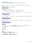
With the use of a Campbell SC32B adapter real-time T-chain data can be displayed.
With the program shown below the CR1000 can operate the T-chain and then parse the
data string to display each sensor’s data. Then with the use of LoggerNet real-time charts
can display the incoming data.
The picture below shows a graph of the 2 temperature sensors that are installed on the Tchain.
Here is a picture of the Dissolved Oxygen sensor also installed on the T-chain.
'CR1000 Series Datalogger
'PME T-Chain Operator
'date: 16-APR-2009
'program author: Garren
'Declare Public Variables
Public PTemp, batt_volt, TNode1, TNode2, ONode, PNode
Public SerialOutput As String * 25
Public SerialInput As String * 50
Public TrimString As String * 50
Public Split(4) As Long
Public Splitter As String *20
'Define Data Tables
DataTable (Test,1,-1)
DataInterval (0,10,Sec,5)
Minimum (1,batt_volt,FP2,0,False)
Sample (1,PTemp,FP2)
Sample (1,TNode1,IEEE4)
Sample (1,TNode2,IEEE4)
Sample (1,ONode,IEEE4)
Sample (1,PNode,IEEE4)
EndTable
'Main Program
BeginProg
Splitter=CHR(32)&CHR(32)&CHR(32)
Scan (2,Sec,0,0)
PanelTemp (PTemp,250)
Battery (Batt_volt)
SerialOpen (COMME,9600,0,0,10000)
SerialOutput=CHR(13)
SerialOut (COMME,SerialOutput,"",0,1000)
SerialIn(SerialInput,COMME,10,13,400)
TrimString= Trim(SerialInput)&Splitter
SplitStr (Split(1),TrimString,Splitter,4,5)
TNode1 = Split(1) 'Converts number into engineering unit
TNode2 = Split(3) 'Converts number into engineering unit
ONode = Split(2) 'Converts number into engineering unit
PNode = Split(4) 'Converts number into engineering unit
CallTable Test
NextScan
EndProg
Hardware Installation
This section describes how to install a PME T-Chain I/O cable assembly into a
Campbell enclosure and how to connect the T-Chain to the CR1000 data logger.
The CR800 series and CR3000 data loggers have the same connections.
It assumes that the Campbell enclosure has the 1.7” diameter standard hole that
Campbell uses for its sealable conduit.
The 6738 RS-232 T-Chain I/O Cable Assembly can also be used with a 1”
diameter custom-drilled hole. In this case the washers are not installed.
INSTALL THE BULKHEAD CONNECTOR TO THE ENCLOSURE
Remove the Campbell PVC pipe fitting from the hole punched in the bottom of
the logger enclosure. Inside the enclosure is a threaded cap that can be
unscrewed from the outside PVC pipe.
Remove the backshell of the DB-9 connector (connector assembly supplied by
PME) by unscrewing the two screws holding it together. (photo below)
Feed the DB-9 connector end of the I/O cable through the enclosure’s hole. (left
photo) The connector assembly is supplied with two washers already installed
on the wire. (right photo)
Carefully feed the bare DB-9 connector through the metal 2” OD washer first and
then through the hex nut. Make sure the wires attached to the DB-9 connector do
not break. (photo below)
At this time, check to see if the smaller washer (approximately 1.7” OD) will fit
within the hole of the enclosure. If the washer does not fit, then remove it and file
or grind it down until it does. Be careful not to nick the cable. Alternately, the
hole in the Campbell enclosure can be filed a little larger. If the hole is 1”
diameter (custom-drilled), then do not use washers.
Place a light coating of silicone adhesive (PME supplied DAP Household
Adhesive Sealant or similar one) between the outer washer and the enclosure.
(photo below) The intent here is to seal the washer to the enclosure. Be careful
that no adhesive flows between the connector and the washer. The connector
has an o-ring that accomplishes the seal at this point. If the hole is 1” diameter
(custom-drilled), then do not use washers or the silicone adhesive.
Press the bulkhead connector and washer against the enclosure and adhesive.
Install the inner washer, larger washer and nut onto the cable assembly. (left
photo)
Make sure the inner, smaller washer fits snugly within the hole. Tighten the nut
very firmly by hand, enough to engage the o-ring seal in the connector and to
resist rotation when the T-Chain is plugged/unplugged. (right photo)
PME does not recommend the use of a wrench since the connector will not
withstand a high level of torque. If a wrench is used, then do not tighten beyond
40 in-lbs. Over-tightening will definitely break the bulkhead connector so be
careful.
Wipe off any excess silicone around the washer.
REINSTALL BACKSHELL ON DB-9 CONNECTOR
Place the DB-9 connector onto half of the backshell with the stress relief clip
around the shrink tubing of the cable. (left photo)
Install the screws through the holes in the connector and onto the other half of
the backshell. Notice that the screws going through the holes in the DB-9
connector are not threaded the whole length of the shaft. (right photo)
Place the other half of the backshell in position on the bottom half. Insert the nuts
into the grooves on the bottom side and tighten the screws such that the
backshell clamps down on the shrink tubing. (photo below)
ELECTRICAL CONNECTION TO RS-232 PORT
DO THE FOLLOWING CONNECTION WITH ALL POWER OFF!!
Plug the male-to-male null adapter onto the RS-232 port and tighten the screws
to hold it in place. (photo below)
Next, plug the DB-9 connector into the male-to-male null adapter and tighten the
screws so the connector will not dislodge when pulled. (photo below)
Install the black wire (T-Chain power return), from the T-Chain cable assembly,
to the GROUND LUG on the logger. (left photo) The Campbell teal-colored
ground wire should also be connected to this lug and to the screw below the hex
nut. (right photo)
Install the red wire (T-Chain Power), from the T-Chain cable assembly, to either
the 12 V or SW-12 V ports (this depends on what type of power configuration you
are using). Back the screw off so that the tinned part of the bare wire can easily
slide into place. Tighten the screw onto the bare wire. Gently pull on the wire to
make sure it will not come out. (photo below)
DO NOT CONNECT THE T-CHAIN TO THE BULKHEAD CONNECTOR WITH
THE LOGGER POWERED. Doing so can electrically harm the T-Chain.
The T-Chain can also be connected to the logger using the SMD-SIO1 module
purchased separately from Campbell Scientific. Contact them for more
information.
DO NOT CONNECT THE T-CHAIN TO THE COM PORTS! The T-Chain will not
work with the four COM ports (1-4) on the logger. Contact Campbell Scientific for
more information.
INSTALLING THE DUMMY PLUG
DO NOT DISCONNECT THE T-CHAIN FROM THE BULKHEAD
CONNECTOR WITH THE LOGGER POWERED. Doing so can electrically harm
the T-Chain.
Check for debris inside the dummy plug and on the outside of the bulkhead connector.
Clean the surfaces if required (wipe with a napkin or paper towel). Debris can lead to a
bad seal between the plug and bulkhead.
Note that pin 1 of the bulkhead connector is larger than the rest of the pins. Pin 1 will
align with the dots on the outside of the dummy plug. Align the dummy plug with pin 1
of the bulkhead and slide on the dummy plug. There is a notch on the bulkhead connector
above pin 1 to help align the dummy plug. (photos below)
Air can get trapped inside the dummy plug so take a flathead screwdriver and carefully
jam it between the plug and bulkhead threads. Twist the screwdriver such that the air is
allowed to escape. (photo below)
Next, firmly press the dummy plug against the bulkhead connector making sure it is all
the way against the bulkhead threads.
Finally, install the locking sleeve for the dummy plug. Slide the sleeve over the plug with
the threads pointed toward the bulkhead connector (away from the enclosure). Once the
sleeve passes over the ring on the plug, then gently twist the sleeve on to the threads of
the bulkhead. There is no need to overtighten the locking sleeve – doing so can damage
it.
T-CHAIN INSTALLATION
DO NOT CONNECT THE T-CHAIN TO THE BULKHEAD CONNECTOR WITH
THE LOGGER POWERED!
These steps are similar to the ones used in the section, Installing the Dummy Plug.
Check for debris inside of the underwater connector and on the outside of the
bulkhead connector. Clean the surfaces if required (wipe with a napkin or paper
towel). Debris can lead to a bad seal between the underwater connector and the
bulkhead connector.
Note that pin 1 of the bulkhead connector is larger than the rest of the pins. Pin 1 will
align with the dots on the outside of the T-chain’s underwater connector. Align the
underwater connector with pin 1 of the bulkhead connector and slide on the underwater
connector. There is a notch on the bulkhead connector above pin 1 to help align the
underwater connector.
Air can get trapped inside the underwater connector so take a flathead screwdriver and
carefully jam it between the underwater connector and bulkhead connector threads. Twist
the screwdriver such that the air is allowed to escape.
Firmly press the underwater connector against the bulkhead connector making sure that it
is all the way against the bulkhead threads.
Finally, slide on the locking sleeve for the underwater connector. Once the sleeve passes
over the ring on the underwater connector, gently twist the sleeve on to the threads of the
bulkhead connector. There is no need to overtighten the locking sleeve – doing so can
damage it.
OVERALL VIEW INSIDE ENCLOSURE