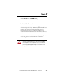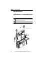
1
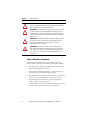
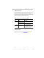
User Manual
Safe Torque Off Option for
PowerFlex 700S Phase II AC Drives and
PowerFlex 700L Liquid-Cooled AC Drives
Catalog Number 20D-P2-DG01
Original Instructions
Important User Information
Solid state equipment has operational characteristics differing from those of
electromechanical equipment. Safety Guidelines for the Application, Installation and
Maintenance of Solid State Controls (Publication SGI-1.1 available from your local
Rockwell Automation sales office or online at http://www.rockwellautomation.com/
literature/) describes some important differences between solid-state equipment and
hard-wired electromechanical devices. Because of this difference, and also because of the
wide variety of uses for solid state equipment, all persons responsible for applying this
equipment must satisfy themselves that each intended application of this equipment is
acceptable.
In no event will Rockwell Automation, Inc. be responsible or liable for indirect or
consequential damages resulting from the use or application of this equipment.
The examples and diagrams in this manual are included solely for illustrative purposes.
Because of the many variables and requirements associated with any particular
installation, Rockwell Automation, Inc. cannot assume responsibility or liability for
actual use based on the examples and diagrams.
No patent liability is assumed by Rockwell Automation, Inc. with respect to use of
information, circuits, equipment, or software described in this manual.
Reproduction of the contents of this manual, in whole or in part, without written
permission of Rockwell Automation, Inc. is prohibited.
Throughout this manual, when necessary we use notes to make you aware of safety
considerations.
WARNING: Identifies information about practices or
circumstances that can cause an explosion in a hazardous
environment, which may lead to personal injury or death, property
damage, or economic loss.
ATTENTION: Identifies information about practices or
circumstances that can lead to personal injury or death, property
damage, or economic loss. Attentions help you identify a hazard,
avoid a hazard, and recognize the consequences.
SHOCK HAZARD: Labels may be on or inside the equipment, for
example, a drive or motor, to alert people that dangerous voltage
may be present.
BURN HAZARD: Labels may be on or inside the equipment, for
example, a drive or motor, to alert people that surfaces may reach
dangerous temperatures.
IMPORTANT
Identifies information that is critical for successful application and
understanding of the product.
Allen-Bradley, Rockwell Software, Rockwell Automation, and TechConnect are trademarks of Rockwell Automation, Inc.
Trademarks not belonging to Rockwell Automation are property of their respective companies.
Summary of Changes
This manual contains new and updated information.
New and Updated Information
The following changes apply to this revision of the manual.
Change
Added “Original Instructions” to the front cover.
Updated the Important statement regarding the proper use of the Safe
Torque Off option.
Updated the information in the Evaluation/Certification by TÜV Rheinland
Group table to support frame 5 and 6 and frames 9…14 drives.
Updated the information in the PFD and PFH for 20-year Proof Test
Interval table to support frame 9…14 drives.
Added steps for installing the Safe Torque Off option board in frame
9…14 drives.
Added frames 9…14 drives to wiring diagram example 2.
Rockwell Automation Publication 20D-UM007G-EN-P - March 2012
See Page…
–
7
9
12
17
32
3
Summary of Changes
4
Rockwell Automation Publication 20D-UM007G-EN-P - March 2012
Table of Contents
Chapter 1
General Description
What Is the DriveGuard Safe Torque Off Option? . . . . . . . . . . . . . . . 7
Safety of Machinery Standards . . . . . . . . . . . . . . . . . . . . . . . . . . . . . . . . . 8
Safety Certifications. . . . . . . . . . . . . . . . . . . . . . . . . . . . . . . . . . . . . . . . . . . 9
Evaluation/Certification by TÜV Rheinland Group . . . . . . . . . . 9
Certifications Online. . . . . . . . . . . . . . . . . . . . . . . . . . . . . . . . . . . . . . . 9
Important Safety Considerations . . . . . . . . . . . . . . . . . . . . . . . . . . . . . . 10
Safety Category 3 Performance Definition . . . . . . . . . . . . . . . . . . . . . 11
Stop Category Definitions . . . . . . . . . . . . . . . . . . . . . . . . . . . . . . . . . . . . 11
Performance Level and Safety Integrity Level (SIL) CL2. . . . . . . . . 12
PFD and PFH Definitions . . . . . . . . . . . . . . . . . . . . . . . . . . . . . . . . . . . . 12
PFD and PFH Data . . . . . . . . . . . . . . . . . . . . . . . . . . . . . . . . . . . . . . . . . . 12
PFD and PFH for 20-year Proof Test Interval . . . . . . . . . . . . . . . 12
Functional Proof Tests . . . . . . . . . . . . . . . . . . . . . . . . . . . . . . . . . . . . . . . . 13
Contact Information if Safety Option Failure Occurs . . . . . . . . . . . 13
Chapter 2
Installation and Wiring
Pre-Installation Instructions. . . . . . . . . . . . . . . . . . . . . . . . . . . . . . . . . . . 15
Option Board Installation . . . . . . . . . . . . . . . . . . . . . . . . . . . . . . . . . . . . 16
PowerFlex 700S Frames 1…6 and PowerFlex 700L Frames
3A and 3B . . . . . . . . . . . . . . . . . . . . . . . . . . . . . . . . . . . . . . . . . . . . . . . . 16
PowerFlex 700S Frames 9…14 . . . . . . . . . . . . . . . . . . . . . . . . . . . . . . 17
PowerFlex 700S, All Frames, and PowerFlex 700L, Frame 3 . . . 18
PowerFlex 700S Frames 1…6 . . . . . . . . . . . . . . . . . . . . . . . . . . . . . . . 23
PowerFlex 700S Frames 9…14 . . . . . . . . . . . . . . . . . . . . . . . . . . . . . . 23
PowerFlex 700L Frames 3A and 3B . . . . . . . . . . . . . . . . . . . . . . . . . 24
Wiring . . . . . . . . . . . . . . . . . . . . . . . . . . . . . . . . . . . . . . . . . . . . . . . . . . . . . . 25
Configure Hardware Enable . . . . . . . . . . . . . . . . . . . . . . . . . . . . . . . . . . 26
Configure Digital Outputs. . . . . . . . . . . . . . . . . . . . . . . . . . . . . . . . . . . . 27
Linking Parameters. . . . . . . . . . . . . . . . . . . . . . . . . . . . . . . . . . . . . . . . . . . 27
Verify Operations . . . . . . . . . . . . . . . . . . . . . . . . . . . . . . . . . . . . . . . . . . . . 28
Rockwell Automation Publication 20D-UM007G-EN-P - March 2012
5
Table of Contents
Chapter 3
Description of Operation
DriveGuard Safe Torque Off Operation . . . . . . . . . . . . . . . . . . . . . . . . 29
Connection Examples . . . . . . . . . . . . . . . . . . . . . . . . . . . . . . . . . . . . . . . . 31
Example 1 - PowerFlex 700S Drives, Frames 1…6
Safe Torque Off Connection with Coast-to-Stop Action, Dual
Channel. . . . . . . . . . . . . . . . . . . . . . . . . . . . . . . . . . . . . . . . . . . . . . . . . . 31
Example 2 - PowerFlex 700S Drives, Frames 9…14 and PowerFlex
700L Drives, Frames 3A and 3B
Safe Torque Off Connection with Coast-to-Stop Action, Dual
Channel. . . . . . . . . . . . . . . . . . . . . . . . . . . . . . . . . . . . . . . . . . . . . . . . . . 32
Example 3 - All Drives
Safe Torque Off Connection with Controlled Stop Action, Dual
Channel. . . . . . . . . . . . . . . . . . . . . . . . . . . . . . . . . . . . . . . . . . . . . . . . . . 33
Index
6
Rockwell Automation Publication 20D-UM007G-EN-P - March 2012
Chapter 1
General Description
The DriveGuard Safe Torque Off option, when used with other safety
components, helps provide protection to meet the requirements for SIL CL2
and Category 3 or PL d class applications. Safety requirements are based on
the standards current at the time of certification.
The DriveGuard Safe Torque Off option is just one component in a safety
control system. Components in the system must be chosen and applied
appropriately to achieve the desired level of operator safeguarding.
What Is the DriveGuard Safe Torque Off Option?
The DriveGuard Safe Torque Off option:
•
Is designed to help safely remove power from the gate firing circuits of the
drive’s output power devices (IGBT’s). This helps prevent the drive’s
output power devices from switching in the pattern necessary to generate
rotation at the motor.
•
Can be used in combination with other safety devices to satisfy the Safe
Torque Off requirements of SIL CL2, according to EN 61800-5-2,
IEC 61508, and EN 62061 Performance Level PL d and Category 3
according to EN ISO 13849-1.
IMPORTANT
This option is suitable for performing mechanical work on the drive
system or affected area of a machine only. It does not provide
electrical safety. For electrical maintenance on the drive and/or motor,
equipment must be electrically disconnected from the power source.
The Safe Torque Off option should not be used for non safety-related
stopping of the drive.
Rockwell Automation Publication 20D-UM007G-EN-P - March 2012
7
Chapter 1
General Description
ATTENTION: Electrical Shock Hazard. Verify that all sources of AC and
DC power are de-energized and locked out or tagged out in accordance
with the requirements of ANSI/NFPA 70E, Part II.
ATTENTION: To avoid an electric shock hazard, verify that the voltage
on the bus capacitors has discharged before performing any work on
the drive. Measure the DC bus voltage at the +DC and -DC terminals or
test points (refer to your drive’s User Manual for locations). The voltage
must be zero.
ATTENTION: In Safe Torque Off mode, hazardous voltages may still be
present at the motor. To avoid an electric shock hazard, disconnect
power to the motor and verify that the voltage is zero before
performing any work on the motor.
ATTENTION: In the event of the failure of two output IGBTs in the
drive, when the DriveGuard Safe Torque Off option has controlled the
drive outputs to the off state, the drive may provide energy for up to
180° of rotation in a 2-pole motor before torque production in the
motor ceases.
Safety of Machinery Standards
The DriveGuard Safe Torque Off option meets the following council
directives and the requirements of the following machine safety standards:
8
•
EN 61800-5-2:2007 Adjustable Speed Electrical Power Drives Systems –
Part 5-2 Safety Requirements: Functional
•
EN ISO 13849-1:2008 Safety of Machinery – Safety-related parts of
control systems - Part 1: General Principles for Design
•
EN 62061:2005 Safety of Machinery, Functional safety of safety-related
electrical, electronic and programmable electronic control systems
•
EN 60204-1:2006 Safety of Machinery – Electrical equipment of
machines – Part 1: General Requirements
•
IEC 61508 Part 1-7:1998, 2000, and 2010 Functional safety of electrical
/ electronic / programmable electronic safety-related systems
Rockwell Automation Publication 20D-UM007G-EN-P - March 2012
General Description
Chapter 1
Safety Certifications
The TÜV Rheinland group has approved the DriveGuard Safe Torque Off
option for use in safety-related applications where the de-energized state is
considered to be the safe state. All of the examples related to I/O included in
this manual are based on achieving de-energization as the safe state for typical
Machine Safety and Emergency Shutdown (ESD) systems.
Evaluation/Certification by TÜV Rheinland Group
Drive
Rating
PowerFlex 700S 208/240V and 400/480V
Phase II
Frames 1…6
600/690V Frames 5 and 6
400/480V and 600/690V
Frames 9…14
PowerFlex 700L 400/480V and 600/690V
Liquid-Cooled
Frames 3A and 3B
TUV Report on Safety Function & TUV
Certification
TUV Certificate No. 01/205/5195/12
TUV Report No. 968/EZ 189.01/09
TUV Certificate No. 01/205/5195/12
TUV Report No. 968/EZ 189.02/12
TUV Report and Certificate No.
968/EZ 230.00/06
TUV Certificate No. 01/205/0667/09
TUV Report No. 968/EZ 230.02/09
Certifications Online
See the Product Certifications link at http://ab.com for Declarations of
Conformity, Certificates, and other certifications details.
Rockwell Automation Publication 20D-UM007G-EN-P - March 2012
9
Chapter 1
General Description
Important Safety Considerations
The system user is responsible for:
•
the set-up, safety rating, and validation of any sensors or actuators
connected to the system.
•
completing a system-level risk assessment and reassessing the system any
time a change is made.
•
certification of the system to the desired safety performance level.
•
project management and proof testing.
•
programming the application software and the safety option
configurations in accordance with the information in this manual.
•
access control to the system, including password handling.
•
analyzing all configuration settings and choosing the proper setting to
achieve the required safety rating.
IMPORTANT
When applying Functional Safety, restrict access to qualified,
authorized personnel who are trained and experienced.
ATTENTION: When designing your system, consider how personnel
will exit the machine if the door locks while they are in the machine.
Additional safeguarding devices may be required for your specific
application.
10
Rockwell Automation Publication 20D-UM007G-EN-P - March 2012
General Description
Chapter 1
Safety Category 3 Performance Definition
To achieve Safety Category 3 according to EN ISO 13849-1:2008, the
safety-related parts have to be designed such that:
•
the safety-related parts of machine control systems and/or their protective
equipment, as well as their components, shall be designed, constructed,
selected, assembled, and combined in accordance with relevant standards
so that they can withstand expected conditions.
•
well tried safety principles shall be applied.
•
a single fault in any of its parts does not lead to a loss of safety function.
•
some but not all faults will be detected.
•
the accumulation of undetected faults can lead to loss of safety function.
•
short circuits in the external wiring of the safety inputs is not one of the
faults that can be detected by the system, therefore, according to DIN EN
ISO 13549-2, these cables must be installed so as to be protected against
external damage by cable ducting or armor.
Stop Category Definitions
The selection of a stop category for each stop function must be determined by
a risk assessment.
•
Stop Category 0 is achieved with immediate removal of power to the
actuator, resulting in an uncontrolled coast to stop. See “Description of
Operation” Example 1 on page 31 and Example 2 on page 32.
•
Stop Category 1 is achieved with power available to the machine actuators
to achieve the stop. Power is removed from the actuators when the stop is
achieved. See “Description of Operation” Example 3 on page 33.
IMPORTANT
When designing the machine application, timing and distance should
be considered for a coast to stop (Stop Category 0 or Safe Torque Off).
For more information regarding stop categories, refer to EN 60204-1.
Rockwell Automation Publication 20D-UM007G-EN-P - March 2012
11
Chapter 1
General Description
Performance Level and Safety Integrity Level (SIL) CL2
For safety-related control systems, Performance Level (PL), according to
EN ISO 13849-1, and SIL levels, according to IEC 61508 and EN 62061,
include a rating of the system’s ability to perform its safety functions. All of
the safety-related components of the control system must be included in both
a risk assessment and the determination of the achieved levels.
Refer to the EN ISO 13849-1, IEC 61508, and EN 62061 standards for
complete information on requirements for PL and SIL determination.
PFD and PFH Definitions
Safety-related systems can be classified as operating in either a Low Demand
mode, or in a High Demand/Continuous mode.
•
Low Demand mode: where the frequency of demands for operation made
on a safety-related system is no greater than one per year or no greater
than twice the proof-test frequency.
•
High Demand/Continuous mode: where the frequency of demands for
operation made on a safety-related system is greater than once per year or
greater than twice the proof test interval.
The SIL value for a Low Demand safety-related system is directly related to
order-of-magnitude ranges of its average probability of failure to satisfactorily
perform its safety function on demand or, simply, average probability of
failure on demand (PFD). The SIL value for a High Demand/Continuous
mode safety-related system is directly related to the probability of a dangerous
failure occurring per hour (PFH).
PFD and PFH Data
These PFD and PFH calculations are based on the equations from Part 6 of
IEC 61508 and show worst-case values.
This table provides data for a 20-year proof test interval and demonstrates the
worst-case effect of various configuration changes on the data.
PFD and PFH for 20-year Proof Test Interval
Attribute Test Result Frames 1…6
5.28 x 10⁻⁵
PFDav
PFH
6.00 x 10⁻¹⁰ 1/h
(calculated according to IEC 61508)
MTTFD
High (4023 years)
low (69%)
DCav
12
Test Result Frames 9…14
2.14 x 10⁻⁴
2.64 x 10⁻⁹ 1/h
(calculated according to IEC 61508)
High (11415 years)
low (80%)
Rockwell Automation Publication 20D-UM007G-EN-P - March 2012
General Description
Chapter 1
Functional Proof Tests
The functional safety standards require that functional proof tests be
performed on the equipment used in the system. Proof tests are performed at
user-defined intervals and are dependent upon PFD and PFH values.
IMPORTANT
Your specific application determines the time frame for the proof test
interval.
Contact Information if Safety Option Failure Occurs
If you experience a failure with any safety-certified device, contact your local
Rockwell Automation distributor. With this contact, you can:
•
return the device to Rockwell Automation so the failure is appropriately
logged for the catalog number affected and a record is made of the failure.
•
request a failure analysis (if necessary) to determine the probable cause of
the failure.
Rockwell Automation Publication 20D-UM007G-EN-P - March 2012
13
Chapter 1
General Description
Notes:
14
Rockwell Automation Publication 20D-UM007G-EN-P - March 2012
Chapter 2
Installation and Wiring
Pre-Installation Instructions
Installation must be in accordance with the following steps and must be
carried out by competent personnel. The DriveGuard Safe Torque Off option
is intended to be part of the safety related control system of a machine. Before
installation, a risk assessment should be performed that compares the
DriveGuard Safe Torque Off option specifications and all foreseeable
operational and environmental characteristics of the machine to which it is to
be fitted.
A safety analysis of the machine section controlled by the drive is required to
determine how often the safety function should be tested for proper
operation during the life of the machine.
ATTENTION: The following information is merely a guide for proper
installation. Rockwell Automation, Inc. cannot assume responsibility
for the compliance or the noncompliance to any code, national, local or
otherwise for the proper installation of this equipment. A hazard of
personal injury and/or equipment damage exists if codes are ignored
during installation.
Rockwell Automation Publication 20D-UM007G-EN-P - March 2012
15
Chapter 2
Installation and Wiring
Option Board Installation
PowerFlex 700S Frames 1…6 and PowerFlex 700L Frames 3A and
3B
1. Remove the I/O Control Cassette from the drive.
Task Description
Open the door of the power structure and disconnect the cables that connect to
A the main board.
Loosen the screws on the face of the cassette.
B
Remove the cassette.
C
B
(PowerFlex 700S shown)
A
C
16
Rockwell Automation Publication 20D-UM007G-EN-P - March 2012
Installation and Wiring
Chapter 2
PowerFlex 700S Frames 9…14
1. Remove the I/O Control Cassette from the drive.
Task Description
Open the door of the power structure and carefully disconnect the three cables
A that connect to the main board.
Loosen the thumb screw that holds the metal flange in place.
B
C
Swing the flange and cassette away from the control frame.
D
Loosen the screws on the face of the cassette.
E
Remove the cassette.
A
B
Typical Frames 10…14
C
E
D
Rockwell Automation Publication 20D-UM007G-EN-P - March 2012
17
Chapter 2
Installation and Wiring
PowerFlex 700S, All Frames, and PowerFlex 700L, Frame 3
2. Remove the screws securing the interior cassette cover to gain access to the
Main board.
3. Remove the 2-pin shunt jumper from the 16-15 pin position.
16
15
IMPORTANT
18
If the DriveGuard Safe Torque Off option is removed from the drive,
this jumper must be reinstalled or the drive will not run.
Rockwell Automation Publication 20D-UM007G-EN-P - March 2012
Installation and Wiring
Chapter 2
4. Remove the exterior cassette covers to access the grounding plate.
Rockwell Automation Publication 20D-UM007G-EN-P - March 2012
19
Chapter 2
Installation and Wiring
5. Install the 16-pin stacker connector.
6. Plug the DriveGuard Safe Torque Off option into the 16-pin connector.
0.8…1.1 N•m
(7.0…10.0 lb•in)
7. Install and tighten mounting screws.
20
Rockwell Automation Publication 20D-UM007G-EN-P - March 2012
Installation and Wiring
Chapter 2
8. Install the exterior cassette covers.
➋
➊
Rockwell Automation Publication 20D-UM007G-EN-P - March 2012
21
Chapter 2
Installation and Wiring
9. Install the inside front cover.
0.8…1.1 N•m
(7.0…10.0 lb•in)
10. Reinstall the cassette in the drive.
11. Record the modification on the Field Installed Option label.
22
Rockwell Automation Publication 20D-UM007G-EN-P - March 2012
Installation and Wiring
Chapter 2
PowerFlex 700S Frames 1…6
FIELD INSTALLED OPTIONS
Firmware
Firmware
20-HIM
28-IO20-COMM20B_-DB1-
#:
#:
Date
Date
HIM
I/O
COM Module
Internal Dynamic Brake
Use marker to note
addition of DriveGuard
Safe Torque Off option.
PowerFlex 700S Frames 9…14
Use marker to note addition of
DriveGuard Safe Torque Off option.
FIELD INSTALLED OPTIONS
Firmware
Firmware
20-HIM
28-IO20-COMM20B_-DB1-
#:
#:
Date
Date
HIM
I/O
COM Module
Internal Dynamic Brake
(Frame 10 shown)
Rockwell Automation Publication 20D-UM007G-EN-P - March 2012
23
Chapter 2
Installation and Wiring
PowerFlex 700L Frames 3A and 3B
Input
Filter Bay
Power
Module Bay
Power Module
Bay Door
Cutaway
FIELD INSTALLED OPTIONS
DANGER
Power Module Front,
Bottom Covers Removed
24
DANGER
Firmware
Firmware
20-HIM
28-IO20-COMM20B_-DB1-
#:
#:
Date
Date
HIM
I/O
COM Module
Internal Dynamic Brake
Use marker to note
addition of DriveGuard
Safe Torque Off option.
Rockwell Automation Publication 20D-UM007G-EN-P - March 2012
Installation and Wiring
Chapter 2
Wiring
Important points to remember about wiring:
•
Always use tinned copper wire.
•
Wire with an insulation rating of 600V or greater is recommended.
•
Control wires should be separated from power wires by at least 0.3 meters
(1 foot).
•
All control wires should be shielded cable with the shield earthed on one
end of the cable.
Table 1 - DriveGuard Safe Torque Off Option Terminal Block Specifications
Wire Size Range (1)
Torque
Maximum
Minimum
Maximum
Recommended
1.5 mm2
(16 AWG)
0.14 mm2
(26 AWG)
0.25 N•m
(2.2 lb•in)
0.22 N•m
(1.9 lb•in)
(1) Maximum / minimum that the terminal block will accept - these are not
recommendations.
Table 2 - Wire Types
Wire Type(s)
Description
Minimum
Insulation Rating
Unshielded Per US NEC or applicable
national or local code
NOT RECOMMENDED 300V,
60 degrees C
Multi-conductor shielded cable 0.750 mm2 (18AWG), (140 degrees F)
such as Belden 8770(or equiv.) 3 conductor, shielded.
Shielded
Table 3 - DriveGuard Safe Torque Off Option Terminals Description
A S S E M B LY
ID LABEL
BAR
CODE
LABEL
No. Signal
1
+24V DC
2
24V Common
3
4
1 2 3 4 5 6
Monitor - N.C.
Common - N.C.
Description
Connections for user-supplied power
to energize coil.
33.3 mA typical, 55 mA maximum.
Normally closed contacts for
monitoring relay status.
Maximum Resistive Load:
250V AC / 30V DC / 50 VA / 60 Watts
Maximum Inductive Load:
250V AC / 30V DC / 25 VA / 30 Watts
1 2 3 4 5 6 7 8 9 10111213
Rockwell Automation Publication 20D-UM007G-EN-P - March 2012
25
Chapter 2
Installation and Wiring
Configure Hardware Enable
Ensure that Jumper P22 on the Main Control Board is set to HW Enable
(Pins 2 and 4).
Jumper P22
4
2
4
2
IMPORTANT
26
3
1
3
1
= HW Enable
= No HW Enable
In addition to the correct jumper setting, enable circuitry must be
connected to I/O Terminals 13 and 16. For wiring examples, refer to
the following publications.
• PowerFlex 700S Phase II Drive Frames 1…6 Installation
Instructions, publication 20D-IN024
• PowerFlex 700H and 700S Drive Frames 9…14 Installation
Instructions, publication PFLEX-IN006
Rockwell Automation Publication 20D-UM007G-EN-P - March 2012
Installation and Wiring
Chapter 2
Configure Digital Outputs
Digital Output 1 and 2 (TB2 Terminals 3, 4, and 5) and Relay Output 3
(TB2 Terminals 6, 7, and 8) can be configured to activate external logic in the
event the safety enable diagnostic routine results in an F45 “Enable Health”
fault.
1. Set Par 147 [FW Functions En], Bit 14 “Digital Outs” to 1 (True).
2. Set Par 845 [Dig Out1 Sel], Par 850 [Dig Out2 Sel] or Par 855 [Rly Out3
Sel] to option 0 “User Select”.
3. Link Par 846 [Dig Out1 Data], Par 851 [Dig Out2 Data] or Par 856 [Rly
Out3 Data] to Par 324 [Fault Status 2]. See “Linking Parameters” below.
4. Set Par 847 [Dig Out1 Bit], Par 852 [Dig Out2 Bit] or Par 857 [Rly Out3
Bit] to 12. Par 324 Bit 12 = EnableHealth status.
Linking Parameters
Use the following procedure to establish a link between Par 846 [Dig Out1
Data], Par 851 [Dig Out2 Data] or Par 856 [Rly Out3 Data] and Par 324
[Fault Status 2].
1. Using the drive’s Human Interface Module (HIM), select Parameter from
the Main Menu and press the Enter key.
2. Using the HIM keypad, enter 846, 850, or 856 and press the Enter key.
The parameter value screen will appear.
3. Press ALT and then View (Sel). Next, press the Up or Down Arrow to
change “Present Value” to “Defined Link.” Press the Enter key.
4. Press the Enter key to select the “Link” field. Using the HIM keypad,
enter 324 as the Source Parameter Number and press the Enter key.
The linked parameter can now be viewed two different ways by
repeating the steps above and selecting “Preset Value” or “Define
Link.” If an attempt is made to edit the value of a linked parameter,
“Parameter is Linked!” will be displayed, indicating that the value is
coming from a source parameter and cannot be edited.
5. To remove a link, repeat the steps above and change the source parameter
to zero (0).
Rockwell Automation Publication 20D-UM007G-EN-P - March 2012
27
Chapter 2
Installation and Wiring
Verify Operations
Test the safety function for proper operation after initial installation of the
DriveGuard Safe Torque Off option. Retest the safety function at the
intervals determined by the safety analysis described on page 15.
Verify that both safety channels are functioning according to Table 4 below.
Table 4 - Channel Operation and Verification
Safety Function Status
Safe Torque Off Option
Terminals 1 & 2
PowerFlex 700S/700L
Enable Input
Drive In
Drive In
Drive In
Drive Able
Safe State Stopped State Stopped State
To Run
Safety Channel Operation
No Power
Applied
No Power
Applied
Power
Applied
No Power
Applied
No Power
Applied
Power
Applied
Power
Applied
Power
Applied
Description For Verification
Safe Torque Off Option
Monitor Contact
Terminals 3 & 4
PowerFlex 700S/700L
Drive Inhibits
Param. 156, Bits 1 & 16
28
Closed
Open
Closed
Open
Bit 16 = 0
Bit 1 = 1
Bit 16 = 0
Bit 1 = 1
Bit 16 = 1
Bit 1 = 0
Bit 16 = 0
Bit 1 = 0
Rockwell Automation Publication 20D-UM007G-EN-P - March 2012
Chapter 3
Description of Operation
DriveGuard Safe Torque Off Operation
The DriveGuard Safe Torque Off option disables the drive’s output IGBT’s by
disconnecting the gate control power supply (see Figure 1). When used in
combination with a second safety channel (the Enable input), the system
satisfies the requirements of EN ISO 13849-1, PL d / Category 3 for safe turn
off of torque-producing energy at the output of the drive.
IMPORTANT
The DriveGuard Safe Torque Off option does not eliminate dangerous
voltages at the drive output. Input power to the drive must be turned
off and safety procedures followed before performing any electrical
work on the drive or motor.
ATTENTION: In the event of the failure of two output IGBTs in the
drive, when the DriveGuard Safe Torque Off option has controlled the
drive outputs to the off state, the drive may provide energy for up to
180° of rotation in a 2-pole motor before torque production in the
motor ceases.
Under normal drive operation, the Safe Torque Off relay is energized, the
enable input is energized, and gate control power is available to the gate
control circuit. If either of these inputs is de-energized, the gate control circuit
is disabled and the STS (Status) indicator on the drive will change to a yellow
flashing light. When the enable input is de-energized, parameter 156 [Start
Inhibits], bit 1 “No Enable” is set to “1.” When the Safe Torque Off relay is
de-energized, parameter 156 [Start Inhibits] bit 16 “GateShutDown” is set to
“1.” If both inputs are de-energized, only bit 1 “No Enable” will be set to “1”
because it takes precedence.
To meet EN ISO 13849-1, PL d / Category 3 operation, both safety channel
inputs to the drive must be de-energized to safely turn off output to the
motor. Refer to the following examples for details.
ATTENTION: By itself, the DriveGuard Safe Torque Off option initiates
a coast-to-stop action. Additional protective measures will need to be
applied when an application requires a different stopping action.
Rockwell Automation Publication 20D-UM007G-EN-P - March 2012
29
Chapter 3
Description of Operation
Figure 1 - Drive Safe Torque Off Circuitry
AC Line
Input Power
PowerFlex
700S/700L
+24V DC
Stop
Start
Start/Stop Common
24V DC Common
Gate Control
Power Supply
Safe Off Option
3
Safety
Channel
4
1
2
Gate Control
Circuit
Common
Safety
Channel
Enable
M
30
Rockwell Automation Publication 20D-UM007G-EN-P - March 2012
Description of Operation
Chapter 3
Connection Examples
Example 1 - PowerFlex 700S Drives, Frames 1…6
Safe Torque Off Connection with Coast-to-Stop Action, Dual
Channel
Figure 2 - Stop Category 0 – Coast
AC Line
Input Power
PowerFlex
700S/700L
+24V DC
Stop
Stop
+24V DC
Gate
Start
GuardMaster
Trojan
Start
Start/Stop Common
24V DC Common
A1 S21 S13
31 13 23 X1
Minotaur
MSR9T
A2 S22 S14
32 14 24 X2
Gate Control
Power Supply
Safe Off Option
3
4
1
+24V DC
Common
2
Gate Control
Circuit
Common
Enable
M
Circuit Status
Circuit shown with guard door closed and system ready for normal drive
operation.
Operating Principle
This is a dual channel system with monitoring of the Safe Torque Off circuit
and drive. Opening the guard door will switch the input circuits (S13-S14 &
S21-S22) to the Minotaur monitoring safety relay unit. The output circuits
(13-14 & 23-24) will cause the Safe Torque Off option and drive Enable
circuit to trip and the motor will coast to stop. To restart the drive, the
Minotaur safety relay must first be reset followed by a valid start command to
the drive.
Fault Detection
A single fault detected on the Minotaur safety input circuits will result in the
lock-out of the system at the next operation and will not cause loss of the
safety function.
Rockwell Automation Publication 20D-UM007G-EN-P - March 2012
31
Chapter 3
Description of Operation
Example 2 - PowerFlex 700S Drives, Frames 9…14 and
PowerFlex 700L Drives, Frames 3A and 3B
Safe Torque Off Connection with Coast-to-Stop Action, Dual
Channel
Figure 3 - Stop Category 0 – Coast
AC Line
Input Power
PowerFlex
700S/700L
+24V DC
GuardMaster
Trojan
Stop
Gate
Stop
Start
Start
Start/Stop Common
+24V DC
A1
S21 S11 S52 S12 S22
37 47 57
13 23
S33 S34
Gate Control
Power Supply
Minotaur
MSR138DP
A2 X1 X2 X3 X4 Y39 Y40 38 48 58
+24V DC
Common
24V DC Common
14 24
Y2 Y1
Safe Off Option
3
4
1
2
Gate Control
Circuit
Common
Enable
M
Circuit Status
Circuit shown with guard door closed and system ready for normal drive
operation.
Operating Principle
This is a dual channel system with monitoring of the Safe Torque Off circuit
and drive. Opening the guard door will switch the input circuits (S11-S12 &
S21-S22) to the Minotaur monitoring safety relay unit. The output circuits
(13-14 & 23-24) cause the drive Enable circuit to trip and the motor will
coast to stop. After the programmed delay, the timed output circuits (57-58)
will cause the Safe Torque Off option circuit to trip. To restart the drive, the
Minotaur safety relay must first be reset followed by a valid start command to
the drive.
32
Rockwell Automation Publication 20D-UM007G-EN-P - March 2012
Description of Operation
Chapter 3
Application Considerations
When the hazard analysis for the overall machine determines the need for
external mechanical brakes or other stopping means, the external means shall
be activated after the removal of power for Stop Category 0.
If the Safe Torque Off option sticks ON, the motor will stop on command
due to the enable input. The system cannot be reset when this fault condition
exists.
Example 3 - All Drives
Safe Torque Off Connection with Controlled Stop Action, Dual
Channel
Figure 4 - Stop Category 1 – Controlled
AC Line
Input Power
PowerFlex
700S/700L
+24V DC
GuardMaster
Trojan
Stop
Gate
Stop
Start
Start
Start/Stop Common
+24V DC
A1
S21 S11 S52 S12 S22
37 47 57
13 23
S33 S34
Gate Control
Power Supply
Minotaur
MSR138DP
A2 X1 X2 X3 X4 Y39 Y40 38 48 58
+24V DC
Common
24V DC Common
14 24
Y2 Y1
Safe Off Option
3
4
1
2
Gate Control
Circuit
Common
Enable
M
Circuit Status
Circuit shown with guard door closed and system ready for normal operation.
Rockwell Automation Publication 20D-UM007G-EN-P - March 2012
33
Chapter 3
Description of Operation
Operating Principle
This is a dual channel system with monitoring of the Safe Torque Off circuit
and drive. Opening the guard door will switch the input circuits (S11-S12 &
S21-S22) to the Minotaur monitoring safety relay unit. The output circuits
(13-14) will issue a Stop command to the drive and cause a controlled
deceleration. After the programmed delay, the timed output circuits (47-48 &
57-58) will cause the Safe Torque Off option and the drive Enable circuit to
trip. If the motor is rotating when the trip occurs, it will coast to stop. To
restart the drive, the Minotaur safety relay must first be reset followed by a
valid start command to the drive.
Fault Detection
A single fault detected on the Minotaur safety input circuits will result in the
lock-out of the system at the next operation and will not cause loss of the
safety function.
If the Safe Torque Off option sticks ON, the motor will stop on command
due to the enable input. The system cannot be reset when this fault condition
exists.
34
Rockwell Automation Publication 20D-UM007G-EN-P - March 2012
Index
C
O
coast-to-stop action, dual channel
connection example (frames 1...6),
31
connection example (frames
3A...3B), 32
connection example (frames
9...13), 32
option board
pre-installation instructions, 15
terminal block specifications, 25
wiring, 25
controlled stop action, dual channel
connection example, 33
performance level, 12
D
P
PFD
data, 12
definition, 12
digital output
configuration, 27
PFH
data, 12
definition, 12
DriveGuard Safe Torque Off option
description, 7
operation, 29
probability of a dangerous failure
occurring per hour (PFH)
definition, 12
F
probability of failure on demand (PFD)
definition, 12
functional proof tests, 13
S
H
hardware enable
configuration, 26
I
important safety considerations, 10
safety category 3
definition, 11
safety certifications, 9
safety function operation
verification, 28
SIL (safety integrity) level, 12
stop category 0 definition, 11
stop category 1 definition, 11
L
linking parameters, 27
M
machine safety standards, 8
T
Terminal Block
I/O, 25
TUV Report on Safety Function & TUV
Certification, 9
Rockwell Automation Publication 20D-UM007G-EN-P - March 2012
35
Index
W
wiring
option board, 25
36
Rockwell Automation Publication 20D-UM007G-EN-P - March 2012
Index
Notes:
Rockwell Automation Publication 20D-UM007G-EN-P - March 2012
37
Index
Notes:
38
Rockwell Automation Publication 20D-UM007G-EN-P - March 2012
U.S. Allen-Bradley Drives Technical Support
Tel: (1) 262.512.8176, Fax: (1) 262.512.2222, Email: [email protected], Online: www.ab.com/support/abdrives
*PN-124644*
www.rockwellautomation.com
PN-124644
Power, Control and Information Solutions Headquarters
Americas: Rockwell Automation, 1201 South Second Street, Milwaukee, WI 53204-2496 USA, Tel: (1) 414.382.2000, Fax: (1) 414.382.4444
Europe/Middle East/Africa: Rockwell Automation, Pegasus Park, De Kleetlaan 12a, 1831 Diegem, Belgium, Tel: (32) 2 663 0600, Fax: (32) 2 663 0640
Asia Pacific: Rockwell Automation, Level 14, Core F, Cyberport 3, 100 Cyberport Road, Hong Kong, Tel: (852) 2887 4788, Fax: (852) 2508 1846
Publication 20D-UM007G-EN-P – March 2012
Supersedes 20D-UM007F-EN-P – September 2011
Copyright © 2012 Rockwell Automation, Inc. All rights reserved. Printed in USA.