1
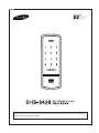
Please review all included documentation and use the product as intended. Safety precautions must be followed to avoid personal injury or property damage. | Table of Contents Introduction & Helpful Tips � ��� Components & Tools 3 4 ��� ��� ��� ��� ��� ��� ��� ��� ��� ��� ��� ��� ��� ��� ��� ��� ��� ��� ��� ��� ��� ��� ��� ��� ��� ��� ��� ��� ��� ��� ��� ��� ��� ��� ��� ��� ��� ��� ��� ��� ��� ��� ��� ��� ��� ��� ��� ��� ��� ��� ��� ��� ��� ��� ��� ��� ��� ��� ��� ��� ��� ��� ��� ��� ��� ��� ��� ��� ��� ��� 6 Basic Lock Operation Overview � ��� ��� ��� ��� ��� ��� ��� ��� ��� ��� ��� ��� ��� ��� ��� ��� ��� ��� ��� ��� ��� ��� ��� ��� ��� ��� ��� ��� ��� ��� ��� ��� ��� ��� ��� ��� ��� ��� ��� ��� ��� ��� ��� ��� ��� ��� ��� ��� ��� ��� ��� ��� ��� ��� ��� Programming Features & Definitions Programming � ��� � ��� ��� ��� ��� ��� ��� ��� ��� ��� ��� ��� ��� ��� ��� ��� ��� ��� ��� ��� ��� ��� ��� ��� ��� ��� ��� ��� ��� ��� ��� ��� ��� ��� ��� ��� ��� ��� ��� ��� ��� ��� ��� ��� ��� ��� ��� ��� ��� �� Troubleshooting � ��� 8 9-12 ��� ��� ��� ��� ��� ��� ��� ��� ��� ��� ��� ��� ��� ��� ��� ��� ��� ��� ��� ��� ��� ��� ��� ��� ��� ��� ��� ��� ��� ��� ��� ��� ��� ��� ��� ��� ��� ��� ��� ��� ��� ��� ��� ��� ��� ��� ��� ��� ��� ��� ��� ��� ��� ��� ��� ��� ��� ��� ��� ��� ��� ��� ��� ��� ��� ��� ��� Miscellaneous Information 13 � ��� ��� ��� ��� ��� ��� ��� ��� ��� ��� ��� ��� ��� ��� ��� ��� ��� ��� ��� ��� ��� ��� ��� ��� ��� ��� ��� ��� ��� ��� ��� ��� ��� ��� ��� ��� ��� ��� ��� ��� ��� ��� ��� ��� ��� ��� ��� ��� ��� ��� ��� ��� ��� ��� ��� ��� ��� ��� 16 ��� ��� ��� ��� ��� ��� ��� ��� ��� ��� ��� ��� ��� ��� ��� ��� ��� ��� ��� ��� ��� ��� ��� ��� ��� ��� ��� ��� ��� ��� ��� ��� ��� ��� ��� ��� ��� ��� ��� ��� ��� ��� ��� ��� ��� ��� ��� ��� ��� ��� ��� ��� ��� ��� ��� ��� ��� ��� ��� ��� ��� ��� ��� ��� ��� 17 Management Number Table � ��� ��� ��� ��� ��� ��� ��� ��� ��� ��� ��� ��� ��� ��� ��� ��� ��� ��� ��� ��� ��� ��� ��� ��� ��� ��� ��� ��� ��� ��� ��� ��� ��� ��� ��� ��� ��� ��� ��� ��� ��� ��� ��� ��� ��� ��� ��� ��� ��� ��� ��� ��� ��� ��� ��� ��� ��� 19 � ��� ��� ��� ��� ��� ��� ��� ��� ��� ��� ��� ��� ��� ��� ��� ��� ��� ��� ��� ��� ��� ��� ��� ��� ��� ��� ��� ��� ��� ��� ��� ��� ��� ��� ��� ��� ��� ��� ��� ��� ��� ��� ��� ��� ��� ��� ��� ��� ��� ��� ��� ��� ��� ��� ��� ��� ��� ��� ��� ��� ��� 20 � ��� ��� ��� ��� ��� ��� ��� ��� ��� ��� ��� ��� ��� ��� ��� ��� ��� ��� ��� ��� ��� ��� ��� ��� ��� ��� ��� ��� ��� ��� ��� ��� ��� ��� ��� ��� ��� ��� ��� ��� ��� ��� ��� ��� ��� ��� ��� ��� ��� ��� ��� ��� ��� ��� ��� ��� ��� ��� ��� ��� ��� ��� ��� ��� ��� ��� ��� ��� ��� ��� ��� 21 Product Specifications Warranty 2 ��� ��� ��� ��� ��� ��� ��� ��� ��� ��� ��� ��� ��� ��� ��� ��� ��� ��� ��� ��� ��� ��� ��� ��� ��� ��� ��� ��� ��� ��� ��� ��� ��� ��� ��� ��� ��� ��� ��� ��� ��� ��� ��� ��� ��� ��� ��� ��� ��� ��� ��� ��� ��� ��� ��� ��� ��� ��� ��� ��� ��� ��� ��� ��� ��� Door Preparation � ��� Installation � ��� ��� ��� ��� ��� ��� ��� ��� ��� ��� ��� ��� ��� ��� ��� ��� ��� ��� ��� ��� ��� ��� ��� ��� ��� ��� ��� ��� ��� ��� ��� ��� ��� ��� ��� ��� ��� ��� ��� ��� ��� ��� ��� ��� ��� ��� ��� ��� ��� ��� ��� ��� ��� ��� ��� ��� ��� ��� ��� � ��� ��� ��� ��� ��� ��� ��� ��� ��� ��� ��� ��� ��� ��� ��� ��� ��� ��� ��� ��� ��� ��� ��� ��� ��� ��� ��� ��� ��� ��� ��� ��� ��� ��� ��� ��� ��� ��� ��� ��� ��� ��� ��� ��� ��� ��� ��� ��� ��� ��� ��� ��� ��� ��� ��� ��� ��� ��� ��� ��� ��� ��� ��� Drilling Template �� ��� ��� ��� ��� ��� ��� ��� ��� ��� ��� ��� ��� ��� ��� ��� ��� ��� ��� ��� ��� ��� ��� ��� ��� ��� ��� ��� ��� ��� ��� ��� ��� ��� ��� ��� ��� ��� ��� ��� ��� ��� ��� ��� ��� ��� ��� ��� ��� ��� ��� ��� ��� ��� ��� ��� ��� ��� ��� ��� ��� ��� ��� ��� ��� ��� 23 | Introduction Congratulations on the purchase of your Samsung Touchpad Door Lock! Your lock has a touch sensitive number display pad and optionally a 13.56MHz Card reader. Up to 70 users can be registered to gain access with unique Codes or Access Cards (supports ISO14443A type). The touchpad makes it convenient to enter the code and the Randomizer function helps prevent lockpicking using fingerprint traces on the touchpad. Other convenient functions such as Automatic Locking / Sound Setting / Out-of-Home Security, etc. provide advanced security and peace of mind. You can unlock the door using video intercom’s monitor after connecting a Samsung video intercom. (Refer to page 6 for connection diagram to a video intercom). | Helpful Tips Do not attempt to repair the product yourself. Change your codes regularly to ensure the security of your codes. Minimize the lock’s exposure to moisture including wet hands and direct contact with liquids. Do not exert excessive force or use sharp instrument on the touchpad. Insert the batteries according to correct polarity. When the low-battery warning sounds, replace all batteries immediately. Do not mix old batteries with new batteries. Use soft, dry cloth to clean the lock and avoid cleaning with water, alcohol or other chemicals. | Components and Tools Components ● Exterior Unit ● Key Tag ● Interior Unit ● User Guide ● Interior Mounting Plate ● Turn Shaft ● Strike ● Screw Pack (6 types) ● Deadbolt ● Magnet ● 4 AA Alkaline Batteries Parts Drawings Exterior Unit Interior Unit Interior Plate Rubber Pad Turn Shaft Deadbolt Strike Magnet Tools Door Preparation Lock Installation ● 2-1/8˝(54mm) hole saw ● 1˝(25mm) hole saw ● 3/8˝(10mm) drill bit ● 1/8˝(2.5mm) drill bit ● Chisel and hammer ● Screw driver #2 ● Drill | Door Preparation Step 1. Check Door Status 1) T his lock supports door thickness of 1-7/32˝ to 1-9/16˝ (31 to 40 mm). 2) Using the provided lock template, ensure that there are no obstructions that would prevent installing the lock properly. 3) Take note of which orientation the deadbolt will need to be installed, left hand or right hand. Left-Handed Door Right-Handed Door When viewed from the Outside, the hinge is on the left. When viewed from the Outside, the hinge is on the right. The hand type is not set by default and it is set to the direction where the magnetic is detected. In order to change the hand type when it is already set, press the [OPEN/CLOSE] button while the magnet is detected from the desired direction. Step 2. Mark the Door Check the location and direction of the deadbolt, attach the drilling template (page 23) on the side of the door, and mark on it with a pen. 1) Align the horizontal line across the door. 2) Align the vertical line over the door. 3) Mark the centers of the holes with the drilling template. 4) Mark the centerline of the deadbolt by aligning it with the vertical line. Step 3. Drilling 1) Drill a 2-1/8˝ (54 mm) diameter hole through the door, as indicated on the template, using a hole saw. 2) Drill a 1˝ (25 mm) mortise hole using a hole saw. 3) Drill strike plate holes using a drill bit (1/8˝, 2.5 mm). ① 54mm ② 25mm ③ 2.5mm Step 4. Strike Plate Installation 1) Using the template, locate the center horizontal line for the deadbolt hole, which lines up with the center of the 2-1/8˝ hole, and draw a horizontal line on the door frame to mark where you will make the deadbolt mortise hole. 2) Measure half the thickness of the door. Now, measure that distance from where the door stops at the frame when the door is closed toward the the door jamb and mark a straight, vertical line the length of the door strike plate. Draw a horizontal line from the mark you made in Step 1 toward the vertical line. Where both lines cross, make a 1˝ (25 mm) diameter hole, 1/2˝ (13 mm) in depth. 3) Align the holes of the strike plate with the vertical line. Trace the outline of the strike plate and mortise with a 1/16˝ (1.6 mm) indentation. Attach the strike plate with the 2 screws provided. (T4 x 15: for wooden door, U10-24 x 9: for metal door) FH+ T4 x 15 | Installation Inside Outside 2 8 3 6a PH+M4×26 6b PH+M4×26 5 1 4 3 1 3c FH+T4x25 FH+ T4 x 25 3a OH+M4x22 FH+ M5 x 20 4 3b FH+ T4 x 25 5 5 7 Connection for video intercom 3c Procedures 1. Insert the deadbolt. 1) Insert the deadbolt from the side of the door. 3) Using two PH+M4 x 26 screws, fasten the upper portion of the Interior Unit (6a). 2) Rotate the deadbolt so the center hole is horizontally aligned from the outside. 4) Using two PH+M4 x 26 screws, fasten the lower portion of the Interior Unit (6b). 3) Fix the deadbolt using two FH+T4 x 25 screws. (T4x25/T4x15: for wooden door, U10-24x14: for steel door) 7. Install the magnet after seeing page 23 to 26 for information about the drilling template sheet. 2. Insert the Exterior Unit. The hand type is not set by default and it (Ensure the Exterior Unit is aligned with the center hole of the deadbolt.) is set to the direction where the magnetic is detected. In order to change the hand type when it is 3. C onnect the Interior Mounting Plate. 1) Detach the Interior Mounting Plate from the Interior Unit. already set, press the [OPEN/CLOSE] button 2) First, install the two OH+M4 x 22 screws (3a) 90% of the way. direction. while the magnet is detected from the desired CAUTION: If the magnet is not detected, automatic lock does not work. 3) Next, fasten the Interior Mounting Plate with three FH+M5 x 20 screws (3b). So be sure to install it with the specified gap size. 4) Align the Exterior Unit with the Interior Mounting Plate and then fasten the Interior Mounting Plate using four FH+T4X25 screws (3c). 8. Install 4 Alkaline batteries. A melody will sound when all 4 batteries are installed correctly. 5) Tighten all screws on the Interior Mounting Plate 100%. CAUTION: Press the [OPEN/CLOSE] button to check whether the dead bolt works properly. 4. W hile the deadbolt is in the open position, insert the turn shaft. 5. Connect the cable to the Interior Unit. Connect the video intercom Connect the cable of video intercom to the Interior Unit. 6. F ix screws for the Interior Unit. 1) Align the Interior Unit on to the Interior Mounting Plate, and check that the Manual switchgear operates correctly. (Ensure cables are arranged neatly to prevent them from getting entangled or being compressed.) 2) Open the battery cover of the Interior Unit. (There are screw grooves at the upper left and right corners.) SHS-3420 is compatible with SHT-3005 and other Samsung video intercom systems. | Basic Lock Operation Overview Opening the Door with a PIN Code → Press the [Wake Up] button. The number pad will illuminate. (If the Random Secu- Enter the PIN Code and press the [ ] button. rity function is enabled, press the 2 illuminated numbers.) Successful: Ding dong dang dong The door opens within one second. Failed: Ding dong ding dong Opening the Door with a Card → Press the [Wake Up] button. Touch the Card reader with an Access Card. Successful: Ding dong dang dong Failed: Ding dong ding dong The door opens within one second. | Programming Features Outside Inside Battery Cover Open Button Auto/Manual Switch IR Sensor Registration Button Manual Switchgear Number Pad Double Lock Lever Open/Close Button Display Lamp Volume Switch Wake Up Button Battery Cover Card Reader External Power Contact RestartButton button Reset Symbols Description Symbols Press the [Wake Up] button on the Exterior Unit. It is used to Description Press the [ ] button. It is used to initiate Pin code or card access or to quit the registration mode. complete number entry. Press the [Registration] button. It is used to change the PIN Code or set other functions. Enter the Master PIN Code (4~12 digits). Factory Default: 1234 R: Press the [Registration] 5 10 button briefly (~1 second) R5: Press the [Registration] button for 5 seconds Press the Number buttons. R10: Press the [Registration ] button for 10 seconds Symbols Description Symbols Description Enter the User PIN Code (4~12 Repeat the process inside the digits). rectangle. Touch the Card reader with the Press the [OPEN/CLOSE] button. User Card. Enter the User/Management Number. Can be set from 1 to 70. Sound Icon Display. Sound Indicators Sound Description Fur Elise Tiritiritiriririri Low voltage warning sound accompanied with [OPEN/CLOSE] button flashing red. Ding Button input sound Ding dong ding dong Error sound Ding dong dang Success sound Ding dong Input standby sound Toot~ toot~ (10 seconds) Malfunction prevention warning Ti~ ti~ ti~ ti~ (5 minutes) Intrusion Detection/Out-of-home Security warning Too~~t, too~~t Double locking sound 10 | Definitions Double Authentication Mode : This mode requires both User Card and PIN Code to open the door, ensuring more security. However, Master PIN Code can open the door regardless of mode. This mode is disabled by default. Double-locking : Double-locking prevents the lock from being unlocked from the outside. You can enable it by using the Double lock lever. Double-locking enable Double-locking disable Emergency Power Supply : Continuing to use the lock without replacing batteries when required will lead to the batteries discharging and cause the lock to malfunction. You can open the door by touching the external power contacts on the Exterior Unit with a 9V battery and then touching with the Card or entering the PIN Code. Indicator Lamp : Indicates the operational status when the Card is being read or the lock is in operation. Infrared Ray Sensor : This sensor detects movement on the inside with an infrared ray when the door opens by pressing [Open/Close] button. It prevents the door being opened by abnormal methods. You can enable or disable this sensor. This sensor is disabled by default. Intrusion Detection Function : When the Interior Unit is forcibly detached while the door is locked, it is detected by the magnetic sensor and an alarm is sounded. (The function is not activated when the magnet is not used.)The Intrusion Detection function is a basic function and cannot be enabled or disabled. Locking Mode (Auto/Manual) : You can enable or disable the function for locking the door automatically when it is closed. The factory default is ‘Auto mode’. - Auto: The door is locked automatically 2 seconds after it is closed. However, it does not function if the magnet is not used or the batteries are completely discharged. - Manual: When the door does not lock automatically when it is closed, pressing the [Wake-Up] button or the [OPEN/CLOSE] button on the Interior Unit will lock the door. Low Voltage : Refers to the state when the operating voltage of the lock is lower than the standard voltage, and activates the Low Voltage Alarm (“Fur Elise”) to indicate that the batteries need to be replaced. Use the Emergency Power when the batteries are completely discharged. Magnetic Sensor : Detects the opening and closing of the door. Malfunction Prevention Function (Mischief Prevention Function) : When more than 5 failed authentication attempts with unregistered PIN Codes/Cards occur, a warning sounds for 10 seconds, and the lock stops operating for 3 minutes. While lock operation is stopped, a ‘beep’ is sounded every 10 seconds and the lock is activated again automatically after 3 minutes. The Malfunction Prevention function is a basic function and cannot be enabled or disabled. Manual Switchgear : When the batteries are completely discharged, this device is used to mechanically lock or unlock the door from inside. Master PIN Code : You can enter only one Master PIN (4-12 digits) Code. You can register the User PIN Codes/Cards after authenticating with the Master PIN (4-12 digits) Code. You can open the door with the Master PIN Code, and the factory default is ‘1234’. OPEN/CLOSE Button : A one-touch button to open the locked door. (It is also used to lock the door from inside in the Manual locking mode.) Out-of-Home Security Function : This function prevents intrusions from outside when no one is home. Pressing the [OPEN/CLOSE] button while the Out-of-Home function is enabled sounds an alarm. You can enable this function with either the Master PIN code or the User PIN Codes. Random Security Function : This mode prevents the disclosure of the PIN Code by entering the PIN Code after authenticating 2 arbitrarily selected numbers. When the buttons for 2 arbitrarily selected numbers are illuminated, pressing the 2 illuminated buttons illuminates the whole number pad. You can enable or disable the Random Security function. This function is enabled by default. 11 Registration Button : This button is used to change Master PIN Code/User PIN Codes/User Cards or the lock settings. It is found below the battery cover of the Interior Unit. The length of time the [Registration] button is pressed varies depending on the function. Resetting : Deletes all registered information and restores the factory default. After resetting, change the Master PIN Code for security. Restart Button : This button resets the lock when the lock stops functioning. Registered information is not deleted. Sound Setting : The volume during the input of numbers and opening or locking of the door can be set from Level 0 ~ Level 2. The sound is muted at Level 0 and is at maximum volume at Level 2. The registration mode operates at Level 1 regardless of the sound setting. User Card : You can register up to 70 User Cards including the User PIN Codes. You can open the door with a User Card. User/Management Number : It is the same number as the registered user’s address and can be set from 1 to 70. The User Number should be managed with caution as it is used to register or delete User PIN Codes/Cards. User PIN Code : You can register up to 70 User PIN Codes (4-12 digits) including the User Cards. You can open the door with a User PIN Code. Wake Up Button : Pressing this button activates the number pad. Enter the PIN Code or touch with the Card while the number pad is illuminated. It is also used to quit the registration mode. Scope of Master, User Settings Settings Factory Defaults Master User Function Opening the Door Master PIN Code Setting Up the Sound Volume Changing Master PIN Code User PIN Code/Card None Registering User PIN Code/Card Locking Mode Auto Deletion of User PIN Code/Card Out-of-home Security Function Disabled Setting the Locking Mode Double-locking Disabled Setting Out-of-home Security Random Security Enabled Setting Double-locking Double Authentication Mode Disabled Setting Random Security Infrared Ray Sensor Disabled Factory Reset Setting the Infrared Ray Sensor Setting the Double Authentication Mode 12 Factory Defaults 1234 Level 1 | Programming Note: Pressing the [Registration] button is only available while the door is open. (Deadbolt must be unlocked.) Changing the Master PIN Code Open the battery cover of the When the number pad is illuminated, en- Enter the new Master PIN Code Interior Unit and press the [Registration] button briefly. ter the current Master PIN Code (default is ‘1234’) and press the [ ] button. and press the [ ] button. Successful: Ding dong dang Failed: Ding dong ding dong Note: Master PIN Code must be 4~12 digits. Successful: Ding dong Failed: Ding dong ding dong Ding dong R Registering a User PIN Code Open the bat- tery cover of the Interior Unit and press the [Registration] button briefly. Ding dong When the number pad is illuminated, enter the current Master PIN Code (default is ‘1234’) and press the [ ] button. Successful: Ding dong Failed: Ding dong ding dong Enter a User Number Enter a new User (1~70*) to register the User PIN Code and press the [ ] button. *Choose a User Number PIN Code and press [ ] button. Successful: Ding dong dang that has not already been used. Successful: Ding dong Failed: Ding dong ding dong Failed: Ding dong ding dong Note: User PIN Code must be 4~12 digits. R 13 Enter another User Number or press the [Wake Up] button to quit. Registering a User Card When the number pad is illuminated, enter the current Master PIN Code (default is ‘1234’) and press the Open the battery cover of the Interior Unit and press the [Registration] button briefly. Ding dong [ ] button. Successful: Ding dong Failed: Ding dong ding dong Touch the Card reader with Enter another User Number or the Card to register. Ding dong dang press the [Wake Up] button to quit. Enter a User Number (1~70*) to register the User Card code and press the [ ] button. * Choose a User Number that has not already been used. Successful: Ding dong Failed: Ding dong ding dong R User PIN Code / Card Deletion Open the battery cover of the Interior Unit and press and hold the [Registration] button for 5 seconds. Ding dong → Ding ding Enter the Master PIN Code and press the [ ] button. Successful: Ding dong Failed: Ding dong ding dong R 14 Enter the User Number (1 to 70) of the User PIN Code or card to be deleted and press the [ ] button. Successful: Ding dong dang Failed: Ding dong ding dong Setting the Out-of-Home Security Function Press and hold the [Wake Up] button on the outdoor Press and hold the [#] button on the outdoor assembly for 3 Enter the Master PIN Code or User PIN Code and press the [ ] assembly while the door is locked. seconds. Too~~t, too~~t button to set the security function. Too~~~t Additional Functions Enable Infrared Ray Sensor R Disable Infrared Ray Sensor Enable Double Authentication Mode 6 Disable Double Authentication Mode Enable Random Security 15 | Miscellaneous Information Reset to Factory Default Resetting the lock will delete all registered information. Note: After Reset, let the sensor detect the magnet to set the hand type again. All registered Master and user data will be deleted, and the lock will be reset to default settings. (Refer to the Program section on Page 12 for default values.) Press the [Registration] button for 10 seconds. Enter the current Master PIN Code, and press Successful: the [ ] button. Ding dong → Ding ding →Ding ding Successful: Failed: Ding dong dang Ding dong ding dong 9V Battery Emergency Power Continuing to use the lock without replacing the batteries when required will lead to lock malfunction. Touching a 9V DC battery to the external power contacts on the under-side of the Exterior Unit will allow for temporary access (continue touching the battery to the contacts until the lock is open). Restart function Note: Restarting does not delete registered information. If there is no response after pressing the [Wake Up] button, use a pin to press the [Restart] button on the right of the external power contact of the Exterior Unit. 16 | Troubleshooting When the lock doesn’t function correctly, please check the items below. If you can’t resolve the problem, please contact the nearest service center. Problem Resolution Reference ● Check if the batteries are inserted in the correct polarity. There is no power. ● Check that the batteries have a full charge. - ● Check that the Exterior Unit cable has not come loose. I can’t change the Master PIN Code. ● There was a delay while changing the PIN Code. The number pad must be illuminated when changing the PIN Code. Also, after entering the first digit, the next digit must be entered within 10 seconds. ● Replace the batteries if they are discharged. Page 13 ● Refer to the ‘Registering/changing the Master PIN Code’ section in the user manual and try again. Ensure that the Master PIN Code is 4~12 digits long. I can’t register the User PIN Code. I can’t register the User Card. ● The User Number has already been used. Delete the desired User Number and re-register. Page 13 ● Ensure that the User PIN Code is 4~12 digits long. ● The User Number has already been used. Delete the desired User Number and re-register. ● Ensure that the card is touched to the card reader within 10 seconds of entering the User Number. Page 14 ● Check that the registered PIN Code was entered correctly. I entered the PIN Code and pressed the [ ] button, but the door won’t open. ● If the number pad illumination turns off while entering the PIN Code, the button input was not registered. Press the [Wake Up] button to illuminate the number pad and enter the PIN Code again from the beginning. (The number pad illumination is turned off automatically if there is no input within 5 seconds) I can’t unlock the door with my Card. ● The Card is either unregistered or unrecognized. ● The Card must touch the Card reader correctly. I can’t unlock the door with my PIN Code or Card. Check if the Double-locking function has been enabled. When this function is enabled, the lock will not open with a PIN Code or Card. Pressing the [Wake Up] button when the Double-locking function is enabled causes the lock to emit a ‘Too~~t, too~~t’ sound. My PIN Code or Card is authenticated, but the door won’t open. The lock may be malfunctioning. Please contact service center. 17 Page 13 Page 14 Page 15 - The door won’t lock automatically when I close it. ● Check if Auto Locking is set. When Manual Locking is set, pressing the [Wake Up] button locks the door. ● If the door doesn’t lock automatically when Auto Locking is set, then the lock has been installed incorrectly. Page 15 ● The Auto Locking function is not activated when the batteries are completely discharged. Check if the batteries are discharged. I hear the “Too~~t, too~~t” warning sound when I press the [Wake Up] button. When the Double-Locking function is enabled, pressing the [Wake Up] button issues this warning sound. Check if Double-locking is enabled, disable the function and try again. Page 15 The lock issues a different melody (Fur Elise) when I activate it. The sound indicates that it is time to replace the batteries. Replace with new batteries within a week. Page 10 There is no response when I press the [Wake Up] button. ● Use a pin to press the hole on the right of the external power contact of the Exterior Unit. ● If doing the above does nothing, contact the service center. 18 Page 16 | Management Number Table Management No. PIN CODE/CARD User Name Management No. 19 PIN CODE/CARD User Name | Product Specifications Item Specifications Voltage 4 AA Alkaline 1.5V Batteries (LR6) (6V) Emergency Power Source 9V Battery (6LF22) (purchased separately) Operation Method Electronic Control Method (PIN Code entry or Card reading) Weight 1.8Kg (including both inside and Exterior Unit) Exterior Unit Product Dimensions Interior Unit 68.7 mm (W) × 175.1 mm (H) × 21.5 mm (D) 2.70 inch (W) × 6.89 inch (H) × 0.85 inch (D) 90 mm (W) × 164.0 mm (H) × 46.65 mm (D) 3.54 inch (W) × 6.46 inch (H) × 1.84 inch (D) The content of this manual is subject to change without prior notice to the user in order to enhance the performance of the product. 20 LIMITED PRODUCT WARRANTY Installation of the product is considered acceptance of warranty conditions SEOUL COMMTECH CO., LTD (SEOUL COMMTECH) warrants its products to be free from manufacturing defects in materials and workmanship for 12 months from the date of purchase. SEOUL COMMTECH will, within said period, at its option, repair or replace any product failing to operate correctly without charge to the original purchaser or user. This warranty shall not apply to any equipment, or any part thereof, which has been repaired by others, improperly installed, improperly used, abused, altered, damaged, subjected to acts of God, or on which any serial numbers have been altered, defaced or removed. SEOUL COMMTECH does not warrant the performance or sale conditions of the seller/installer. There are no warranties, express or implied, which extend beyond the description on the face hereof. There is no express or implied warranty of merchantability of a warranty of fitness for a particular purpose. Additionally, this warranty is in lieu of all other obligations or liabilities on the part of SEOUL COMMTECH. Any action for breach of warranty, including but not limited to any implied warranty of merchantability, must be brought within the six months following the end of the warranty period. In no case shall SEOUL COMMTECH be liable to anyone for any consequential or incidental damages for breach or this or any other warranty, express or implied, even if the loss or damage is caused by the seller’s own negligence or fault. SEOUL COMMTECH shall have no obligation under this warranty, or otherwise, if the product has been repaired by others, improperly installed, improperly used, abused, altered, damaged, subjected to accident, nuisance, flood, fire or acts of God, or on which any serial numbers have been altered, defaced or removed. SEOUL COMMTECH and its distributor will not be responsible for any dismantling, reassembly or reinstallation charges. This warranty contains the entire warranty. It is the sole warranty and any prior agreements or representations, whether oral or written, are either merged herein or are expressly cancelled. SEOUL COMMTECH neither assumes, nor authorizes any other person purporting to act on its behalf to modify, to change, or to assume for it, any other warranty or liability concerning its products. In no event shall SEOUL COMMTECH be liable for an amount in excess of SEOUL COMMTECH’s original selling price of the product, for any loss or damage, whether direct, indirect, incidental, consequential, or otherwise arising out of any failure of the product. Seller’s warranty, as hereinabove set forth, shall not be enlarged, diminished or affected by and no obligation or liability shall arise or grow out of Seller’s rendering of technical advice or service in connection with Buyer’s order of the goods furnished hereunder. SEOUL COMMTECH recommends that the entire system be completely tested weekly. Warning: Despite frequent testing, and due to, but not limited to, any or all of the following; criminal tampering, electrical or communications disruption, it is possible for the system to fail to perform as expected. SEOUL COMMTECH does not represent that the product/system may not be compromised or circumvented; or that the product or system will prevent any personal injury or property loss by burglary, robbery, fire or otherwise; nor that the product or system will in all cases provide adequate warning or protection. A properly installed and maintained alarm may only reduce risk of burglary, robbery, fire or otherwise but it is not insurance or a guarantee that these events will not occur. 21 Consequently, seller shall have no liability for any personal injury, property damage, or other loss based on a claim the product failed to give warning. Therefore, the installer should in turn advise the consumer to take any and all precautions for his or her safety including, but not limited to, fleeing the premises and calling police or fire department, in order to mitigate the possibilities of harm and/or damage. SEOUL COMMTECH is not an insurer of either the property or safety of the user’s family or employees, and limits its liability for any loss or damage including incidental or consequential damages to SEOUL COMMTECH’s original selling price of the product regardless of the cause of such loss or damage. Some states do not allow limitations on how long an implied warranty lasts or do not allow the exclusion or limitation of incidental or consequential damages, or differentiate in their treatment of limitations of liability for ordinary or gross negligence, so the above limitations or exclusions may not apply to you. This Warranty gives you specific legal rights and you may also have other rights which vary from state to state. In case of the product defect, contact our U.S. Customer Service Center. In order to exercise the warranty, you must contact our U.S. Customer Service Center and obtain a proper RMA # - the product must be returned to our U.S. Customer Service Center at user’s shipping expense and the replacement product will be shipped back at our expense. For outside U.S customer, visit our website at www.scommtech.com/en and go to Support menu to find the contact information of our worldwide distributors. For product service, the product in all cases must be accompanied by below warranty form. Customer must ask the reseller or installer to fill out the warranty form indicated below, otherwise the product warranty may be considered void. Date of Purchase or Installation : (MM/DD/YY) Name, telephone and full address of purchaser : Stamp or Signature of authorized reseller / installer Product Code and Serial Number : 22 | Drilling Template Sheet for 60mm Backset 23 | Drilling Template Sheet for 60mm Magnet 69.0 69.0 2.0 24 | Drilling Template Sheet for 70mm Backset When installing the 60 mm iron door and 70 mm iron/wood door, a separate magnet sensor is applied. 25 Product information and customer service contact : SEOUL COMMTECH EZON® is a registered trademark of SEOUL COMMTECH Co.,Ltd. Other products’ brand names may be trademarks or registered trademarks of their respective owners and are mentioned for reference purposes only. These materials are protected under U.S. copyright laws. All contents current at time of publication. SEOUL COMMTECH Co.,Ltd., reserves the right to change availability of any item in this catalog, its design, construction, and/or its materials. Copyright © 2009, EZON, SEOUL COMMTECH Co.,Ltd. All right reserved. Reproduction in whole or in part without the express written permission of SEOUL COMMTECH is prohibited. GC68-01733A ED:01