1
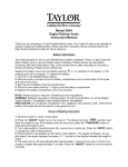
WIRELESS MULTI-ZONE DIGITAL THERMOMETER WITH ALARM CLOCK Model No. 91455 SF Version Instruction Manual FEATURES AND SPECIFICATIONS BASE STATION Indoor / outdoor RF temperature Monitors temperature at up to 4 locations (additional sensors required) Indoor / outdoor temperature displayed in °F or °C Memory function to recall highest/lowest temperature readings Indoor temperature range: 14°F to 158°F (-10°C to 70°C) Temperature tolerance: +/- 2°F (+/- 1.1°C) 12/24 hour selectable alarm clock with snooze Month / Day / Year calendar Countdown timer Low battery indicator Table top or wall mount Requires (2) AAA batteries REMOTE SENSOR 433 MHz transmission frequency Transmission range up to 100 ft. (range may be shorter based on interference present) Temperature range: -4°F to 158°F (-20°C to 70°C) Temperature range via sensor probe: -40°F to 158°F (-40°C to 70°C) Temperature tolerance: +/- 2°F (+/- 1.1°C) Table top or wall mount Requires (2) AAA batteries SET/AL ON/OFF UP C/F SNOOZE DOWN 12/24 RESET ALERT BATTERY INSTALLATION AND SETUP Position the remote sensor near the base station. Open the battery compartment at the back of the base station and insert (2) AAA batteries according to the polarity markings. Replace the battery compartment cover. Press the UP C/F button at the back of the unit to display the temperature in °F or °C. The RF signal icon (located to the left of the outdoor temperature display) will flash for 5 minutes, indicating that the base station is ready to pick up the RF signal from the remote sensor. Register the Remote Sensor Open the battery compartment at the back of the remote sensor and slide the channel selector switch to your desired channel. For the first remote you may select any channel, for additional remotes select any unused channel. Insert (2) AAA batteries according to the polarity markings. Be sure to install the batteries in the remote within the time that the RF signal icon is flashing on the base station. Replace the battery compartment cover. If you have registered more than one sensor, press the CHANNEL button to select the remote channel you want displayed permanently on the base station. Or press CHANNEL until you observe a circular arrow on the base station LCD display under the channel number. The unit will then autoscroll, changing from channel to channel every 5 seconds. Register a Remote Sensor When the RF Signal Icon is not Showing To register a remote sensor when the RF signal icon is not showing on the base station LCD: Press and hold the CHANNEL button for 3-4 seconds until the RF signal icon is showing. Install the batteries in the new remote sensor or if the batteries have already been installed, press either the TX or RESET button, which are located inside the remote battery compartment. Notes: Always replace all batteries at the same time; do not mix old and new batteries. Do not mix alkaline, standard (carbon-zinc) or rechargeable (ni-cad, ni-mh, etc.) batteries. For maximum performance in normal conditions we recommend using good quality alkaline batteries. When temperatures are below 0°F, alkaline batteries can lose power resulting in a loss of remote transmission. If you reside in an area that experiences frequent temperatures near or below 0°F, we recommend using lithium batteries to minimize the loss of transmission. NOTE: please recycle or dispose of batteries per local regulations. WARNING: Batteries may pose a choking hazard. Do not let children handle batteries. PRECAUTION: Do not dispose of batteries in fire. Batteries may explode or leak. Remove the batteries if the thermometer or remote sensor will not be used for a long period of time. Locating the Base Station and Remote Sensor Choose a suitable place for the base station and remote outdoor sensor, within the transmission distance. Place the base unit near a window, but away from direct sunlight or sources of heat or air conditioning to ensure accurate temperature readings. The remote sensor is water resistant, but not waterproof. Locate the sensor out of direct sunlight, in an area where it will not be exposed to rain, snow or ice. The location you choose is critical for maximizing the transmission range. The remote sensor is designed to transmit up to 100 ft. unimpeded. Transmitting through walls, metal doors and metal framed windows may reduce the transmission range. To optimize the transmission distance, the remote should be positioned in a location that minimizes these obstructions. Interference from other sources such as home security systems, wireless doorbells and wireless home entertainment equipment may interrupt the transmission signal temporarily. In areas of extreme low temperatures, re-locate the remote sensor indoors. Plug the sensor wire into the remote and route the wire through a nearby window. Be sure to plug in the wire securely. The sensor wire is not included with the unit and can be purchased separately by contacting Taylor Customer Service at 1-866-843-3905. OPERATING INSTRUCTIONS 12/24 Hour Clock Selection In the normal time display mode, press the DOWN 12/24 button to display the time in 12 hour or 24 hour format. (In 12 hour format AM or PM will show at the left of the time). Setting Time and Date Note: When setting the current time or alarm time, press and hold the UP or DOWN button for fast setting. Press the SET button for 2-3 seconds until the hour is flashing. Press UP or DOWN to set the hour. Press SET and the minutes will be flashing. Press UP or DOWN to set the minutes. Press SET and the month will be flashing. Press UP or DOWN to set the month. Press SET and the date will be flashing. Press UP or DOWN to set the date. Press SET and the year will be flashing. Press UP or DOWN to set the year. Press SET to lock in the settings and return to the normal time display. If no buttons are pressed within 20 seconds, the unit will revert to the normal time display. In any setting mode you can press the CHANNEL button to revert to the normal time display. Note: Use the MODE button to scroll through the various displays. Starting from the normal time display, press MODE to view alarm time 1, alarm time 2, countdown timer, return to normal time. If the display is in any mode other than normal time and no buttons are pushed, within 20 seconds the LCD display will revert to the normal time display. Display the Calendar In normal display mode, press the SET button once to display the time with seconds, press SET again to display the date, press SET again to return to the normal time display. Setting the Alarm Time Two different alarm times can be set, Alarm 1 and Alarm 2. To set Alarm 1; In normal time mode, press the MODE button once and the Alarm 1 time and icon (A1) will show. Press the SET button for 2-3 seconds until the alarm hour flashes. Press UP or DOWN to set the alarm hour. Press SET and the minutes will be flashing. Press UP or DOWN to set the alarm minutes. Press SET to return to normal time display. To set Alarm 2; In normal time mode, press MODE twice and the Alarm 2 time and icon (A2) will show. Follow the same setting sequence as for Alarm 1. Activating the alarm In the normal time display, press the MODE button to choose the alarm (A1 or A2) that you want to activate. Press SET to activate (the alarm bell icon and 1 or 2 will show). The alarm will sound at the time you have entered. Silencing the Alarm When the alarm sounds press any button on the front of the base station to silence the alert or press the SNOOZE button on the back of the unit to activate the snooze function. When snooze is activated the Zzz symbol will appear and the alarm will sound again in 5 minutes. When the alarm sounds again, press SNZ to continue the snooze function or press any button on the front of the base station to discontinue snooze. The alarm icon will remain on the display and the alarm will sound every day at the pre-set time until the alarm is de-activated. De-activating the Alarm To de-activate the alarms, press the MODE button to choose the alarm (A1 or A2) that you want to deactivate. Press the SET button until the alarm bell icon is no longer showing. Your alarm time settings will remain and you can re-activate the alarms by following the instructions above. Min/Max Memory Press the MAX/MIN button once to display the highest indoor and outdoor temperatures recorded since last reset. MAX is shown on the display. Press MAX/MIN a second time to display the lowest indoor and outdoor temperatures recorded since last reset. MIN is shown on the display. To clear and reset the max/min records, when either the MAX or MIN record is shown on the LCD display, press and hold MAX/MIN for 2-3 seconds until the beep sounds. Setting the Temperature Alerts You can program your weather center to sound an alert whenever the indoor or outdoor temperature exceeds the upper or lower pre-set level. The outdoor alert can be set for all remote channels. Setting the Indoor Temperature Alert Press and hold the ALERT button for 3-4 seconds. The high temperature limit icon and indoor temperature will be flashing. Press UP or DOWN to select the high temperature alert level. Press ALERT and the low temperature limit icon and temperature will be flashing. Press UP or DOWN to select the low temperature alert level. Press ALERT to return to normal mode. Press ALERT to activate or de-activate the alert function. When the alert function is activated, both the high and low limit icons will show. Setting the Outdoor Temperature Alert Press and hold the ALERT button for 3-4 seconds. Press CHANNEL to select the channel on which you want to set the alert. (1 to 3) The high temperature limit icon and outdoor temperature for the channel you selected will be flashing. Press UP or DOWN to select the high temperature alert level. Press ALERT and the low temperature limit icon and temperature will be flashing. Press UP or DOWN to select the low temperature alert level. Press ALERT to return to normal mode. Press ALERT to activate or de-activate the alert function. When the alert function is activated, both the high and low limit icons will show. Using the Countdown Timer In the normal display mode, press MODE 3 times to display the countdown timer. TIMER will show on the display. Press the SET button for 3-4 seconds and the hour will be flashing. Press UP or DOWN to set the hour. Press SET and the minutes will be flashing. Press UP or DOWN to set the minutes. Press SET and the seconds will be flashing. Press UP or DOWN to set the seconds. Press SET to lock in the time. Press SET to start the countdown timer. As the timer is counting down you can press SET to pause. Press SET again to re-start the timer. After the timer reaches -00- and the alarm sounds, press any button on the front of the base station to silence the alert. The LCD display will revert to the normal time display. If you want to clear or re-set the timer before the countdown reaches -0-, pause the countdown and enter the new countdown time using the above procedure. RESET Your multi-zone thermometer can be re-set in case of malfunction. Press the RESET button once and the unit will return to its original factory settings. Re-enter your settings according to the OPERATING INSTRUCTIONS. PURCHASING ADDITIONAL SENSORS The remote sensor for this unit is SPRINGFIELD P/N 91465-SF. Additional sensors may be ordered directly from Taylor Customer Service at 1-866-843-3905. Please have a major credit card ready when placing the call. FCC STATEMENT OF COMPLIANCE Caution: Changes or modifications not expressly approved by the party responsible for compliance could void the user’s authority to operate the equipment. Note: This device complies with part 15 of the FCC Rules. Operation is subject to the following two conditions: (1) this device may not cause harmful interference, and (2) this device must accept any interference received, including interference that may cause undesired operation. This equipment has been tested and found to comply with the limits for a Class B digital device, pursuant to part 15 of the FCC rules. These limits are designed to provide reasonable protection against harmful interference in a residential installation. This equipment generates, uses and can radiate radio frequency energy and, if not installed and used in accordance with the instructions, may cause harmful interference to radio communications. However, there is no guarantee that interference will not occur in a particular installation. If this equipment does cause harmful interference to radio or television reception, which can be determined by turning the equipment off and on, the user is encouraged to try to correct the interference by one or more of the following measures: ● Reorient or relocate the receiving antenna. ● Increase the separation between the equipment and receiver. ● Connect the equipment into an outlet on a circuit different from that to which the receiver is connected. ● Consult the dealer or an experienced radio/TV technician for help. ONE (1) YEAR LIMITED WARRANTY This product is warranted against defects in materials or workmanship (excluding batteries) for one (1) year from date of original purchase for the original purchaser. It does not cover damages or wear resulting from accident, misuse, abuse, commercial use, or unauthorized adjustment and/or repair. Should this product require service (or replacement at our option) while under warranty, do not return to retailer. Please pack the item carefully and return it prepaid, along with store receipt showing date of purchase and a note explaining reason for return to: Taylor Precision Products, Inc. / Springfield Precision 2220 Entrada Del Sol, Suite A Las Cruces, New Mexico 88001 1-866-843-3905 www.springfieldprecision.com There are no express warranties except as listed above. This warranty gives you specific legal rights, and you may have other rights which vary from state to state. For additional product information, or warranty information outside the USA, please contact us through www.taylorusa.com or www.springfieldprecision.com. © 2013 Taylor Precision Products, Inc. and its affiliated companies, all rights reserved. Springfield® is a registered trademark of Taylor Precision Products, Inc and its affiliated companies, all rights reserved. Made to our exact specifications in China. CP91455 7.13