1
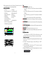
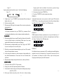
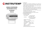
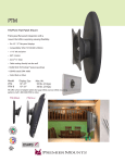
INTELLIGENCE FREQUENCY COUTER OPERATION MANUAL 1. INTRODUCTION: Step Coupling Freq. Range 1 AC 1 AC 2 3 AC AC 3 DC 1GHz-2.4GHz 50MHz-1GHz (no including 1GHz) 2MHz-50MHz 100Hz-2MHz 0.01Hz-100Hz (no including 100Hz) Resolution Gate time min. Gate time max. 1kHz 100Hz 1kHz 10Hz 1kHz 10Hz 10Hz 0.1Hz 0.001Hz It is a high-resolution multifunction intelligent frequency counter based on microprocessor. Features include: frequency, period and equal-precision measuring. Also, 3step function selection, work state, unit and eight-digit LED display. All function depend on a single CPU. A crystal controlled temperature circuit provides constant compensation for temperature change thereby reducing measurement errors typically caused by temperature drift. The CH.B input has an attenuator (x1, x20), & AC/DC coupling for a low-pass filter. The instrument measures signals over a wide range from 0.01Hz to 2.4GHz. The gate time is continuously variable from 100ms to 10s. The instrument provides high performance stability, & function at a low cost. Note: Read this chapter carefully before using your instrument retain these instructions. 2. ELECTRICAL SPECIFICATIONS: Input characteristics: 1) CH.A (0.01Hz~50MHz) frequency range :DC couple 0.01Hz to 100Hz AC couple 100Hz to 50MHz Sensitivity : "AC" 100Hz-50MHz<120mVrms "DC" 0.01Hz-1Hz≤500mVp-p, - 1 - 1Hz-100Hz≤80mVrms. Input impedance : 1M Attenuator : X1, X20 Max. safety voltage : 30V (DC/AC peak) 2) CH.B (50MHz~2.4GHz) Frequency range : from 50MHz to 2.4GHz Sensitivity : 50mVrms~300mVrms Coupling : AC only Input impedance : 50 Max. safety voltage : 3V 3) Resolution: . Resolution depends on gate time control setting. 4) Time base short time stability : ±3X10⁻⁹/second Long time stability : ±2X10⁻⁸/month Temperature drift coefficient :±1X10⁻⁷, 10C ~ 40C Line voltage variation :±1X10⁻⁷ for line voltage±10% 5) Gate time : Continuously variable, from 100ms to 10s. 6) Display : 8 digit, 19X12.5mm LED with steps, frequency, period, kHz/s and MHz/ ms, indicator. 7) Precision : standard time error (t) x frequency (f)±1d 8) Power supply : 220V/110V±10%, 50Hz or 60Hz±10%. 9) Preheat time : 20 minutes 10) Operation environment:-5C ~50C, 10 ~ 90% R.H. Storage .environment : -40C ~60C, 5 ~ 90% R.H. 11) Weight : Approx. 1.6kg 12) Dimension : 270mm X 215mm X100mm 13) Accessories : Manual, power cord, test probe. OPERATION: 1. REQUIREMENTS: a. Power: AC 220V/110V±10%, max. consumption 5W. b. Before measuring, turn the unit on for 20 minutes. This preheats the unit & the crystal oscillator to ensure accurate readings & stability. 2. PANEL DESCRIPTION: 1) CH.A port 2) CH.B port 3) Frequency indication LED 4) Period indication LED 5) LED display 6) KHz/s indication LED 7) MHz/ms indication LED 8) RESET key 9) PERIOD key 10) CONFIRM key 11) FUNCTION key 12) ATT key 13) AC/DC COUPLING key 14) GATE TIME knob 15) POWER SWITCH 16) 220V/110V Transform SWITCH 17) POWER JACK and FUSE BOX 3 2 1 4 5 6 7 A VC3165 B HIGH RESOLUTION COUNTER FREQ. 0.01Hz-50MHz 50MHz-2.4GHz 30V MAX 3V MAX MIN MAX GATE TIME 14 13 PER. AC ATT x1 DC x20 12 11 Function Confirm 10 9 ON Period s kHz ms MHz Reset 8 W A R N IN G 15 16 17 - 2 - Note: FUNCTION KEY 11)FUNCTION 11) KEY: (including 3 steps) 1 Step: 50MHz---2.4GHz range, from CH.B input, measurement unit indication "MHz/ms"; 2 Step: 2MHz---50MHz range, input from CH.A, measurement unit indication "MHz/ms"; 3 Step: 0.01Hz--2MHz range, input from CH.A, measurement unit indication "kHz/s". These are frequency measurement steps and "FREQ." indication LED flicker. PERIOD KEY: Press the key down, the instrument will enter into period measure 9)PERIOD 9) mode. CONFIRM KEY: Press the key down, the instrument will start working according 10)CONFIRM 10) to preset state. 13) AC/DC COUPLING KEY: Press the key down for DC measurement, push the key 13)AC/DC up for AC measurement. RESET KEY 8)RESET 8) KEY: when instrument is abnormal, press it once to reset. ATT KEY 12)ATT 12) KEY: Press the key down for attenuated 20dB measurement, push it up for no attenuator. 2. OPERATION STEPS: First, connect power cord (AC220V/110, 50Hz or 60Hz) and set power switch to ON position. Allow unit to warm up for 20 minutes to ensure accurate readings. Frequency measurement: 1). Select CH.A or CH.B (depends on the range being measured) and connect to signal source by cable. 2). For signal to be measured, if frequency is less than 100Hz, press " AC/DC " coupling key down. 3). If input signal amplitude is high, then press "ATT" key down to ensure the instrument measures an attenuated signal. 4) When the "FUNCTION" key is pressed, the last digit display value is the current selection step, (for figure 2.1 2 step) 2 Figure 2.1 frequency measurement has only three steps (1--3) and its circle displaying; Figure 2.2 1 2 3 5) Complete steps 1-3, press "CONFIRM" key, the instrument will start working and display result, unit, etc. 6) Gate time may adjust variably. 7) When measuring 100Hz signal, the instrument will auto enter into equal-precision measurement state. Period measurement: On frequency measurement state, press "PERIOD" key, instrument will start measuring period and display test result, working state and unit simultaneously. 3. WARNING!!: 1) When measuring high voltage or strong RF signal by cable input, cables should be in series with large resistance to prevent damage. Wireless input of very strong signals should be measured in coarse mode to avoid damage. 2) When instrument is working abnormally or goes "dead", only press the " RESET" key once or turn off power once to reset the system. 3) When there is no input signal, instrument display may not be zero. This is normal, it doesn't effect measurements or accuracy. 4) Avoid exposing this instrument to extreme temperatures, damp conditions, dirt, dust, chemical contamination etc. Do not remove the cover for electrical shock could occur. 5) When instrument working on strong interference source, sensitivity will reduce. 4. FOR EXAMPLE: 1) Connect power cable to AC220V/110V power socket. 2) Setting power switch to ON position and preheat for 20 minutes. 3) Connect attach test cable to input port on front panel, according frequency range to select CH.A or CH.B. 4) Select proper function (step) and gate time. Gate time is shorter, measuring - 3 - frequency speed is faster, but resolution is lower; however, gate time is longer, measuring frequency speed is slower, but resolution is higher. 5) If measure period, press down "PERIOD" key. 6) Press down "CONFIRM" key, then instrument start working. EXAMPLE 1: Analog handset measurement: user may connect test cable to input CH.B and set the FUNCTION key to 1step position, gate time may be selected by need (manual adjust: from 100ms to 10s). Figure 5.1 and figure 5.2 are LED display reads. 1 Figure 5.1 1step 9 0 0 0 0 0 2 Figure 5.2 900MHz EXAMPLE 2: 30MHz interphone emit frequency measurement: user may set the function key to 2 step position and gate time may by selected by need (manual adjust: from 100ms to 10s). Figure 5.3 and figure 5.4 are LED display reads. 2 Figure 5.3 2 step 3 0 0 0 0 0 1 Figure 5.4 30MHz EXAMPLE 3: Self-oscillation frequency measurement (of BP, controlling and controlled telephone, interphone): user may set the function key to 2 step position. Connect one of feet of a 5pF capacitance to red clamp of test cable, the other as probe to directly contact frequency point, then frequency value will be measured. VC3165