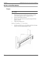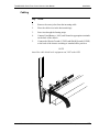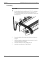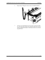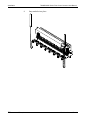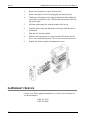
1
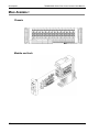
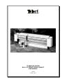
® CONNECTING THE FUTURE ® TELEMIX/4000 SERIES DSX-1/1C/2 FRONT CROSS-CONNECT USER MANUAL 107184 Issue A Rev 1 TeleMIX/4000 Series DSX-1/1C/2 Front Cross-Connect User Manual Document Number 107184 Issue A Rev 1 Copyright© Telect, Inc., 1998, All Rights Reserved. Telect and Connecting the Future are registered trademarks of Telect, Inc., 2111 N. Molter Rd., Liberty Lake, Washington 99019 Note: Telect assumes no liability from the application or use of these products. Neither does Telect convey any license under its patent rights nor the patent rights of others. This document and the products described herein are subject to change without notice. ii Telect, Inc. 107184 Issue A Rev 1 Contents 1 Descriptions TeleMIX/4000 Series Front Cross-Connect ................................ 1-1 Features.................................................................................. 1-1 Main Assembly ............................................................................ 1-2 Chassis ................................................................................... 1-2 Module and Jack .................................................................... 1-2 Dedicated Digital Jack (DDJ™ ) Specifications .......................... 1-3 Electrical ................................................................................ 1-3 Mechanical ............................................................................. 1-3 Environmental........................................................................ 1-4 2 Installation Installation Considerations .......................................................... 2-1 Inspection ..................................................................................... 2-1 Installation Procedure .................................................................. 2-2 Chassis ................................................................................... 2-2 Cabling................................................................................... 2-3 Terminating............................................................................ 2-4 3 Operation Cross-Connecting......................................................................... 3-1 Patching ....................................................................................... 3-1 Two Single Patch Cords ........................................................ 3-2 Dual Patch Cord..................................................................... 3-2 4 Service Owner Maintenance ..................................................................... 4-1 Troubleshooting ........................................................................... 4-1 Issue A Rev 1 107184 Telect, Inc. iii Replacing A Faulty Jack .............................................................. 4-1 In-Warranty Service..................................................................... 4-2 Out-Of-Warranty Service ............................................................ 4-3 Repacking For Shipment ............................................................. 4-3 iv Telect, Inc. 107184 Issue A Rev 1 1 Descriptions TELEMIX/4000 S ERIES FRONT CROSS-CONNECT Telect’s TeleMIX/4000 Series Front Cross-Connect panel provides highdensity cross-connect capability for DS-1/1C/2 circuits. Both the 19" (48.26 cm) and the 23" (58.42 cm) models use the same plug-in, 4-circuit modules using Telect’s patented Dedicated Digital Jack (DDJ ). The 19" (48.26 cm) panel is expandable to 64 circuits; the 23" (58.42 cm) panel is expandable to 84 circuits. Panels mount on EIA or WECO equipment racks. Features • Four-circuit, plug-in module • An internal printed circuit board with gold contacts for power (-48V), return power, and shield ground • Replacable, single-circuit Dedicated Digital Jack (DDJ ) • Red, yellow, or green LEDs • Attached front jumper tray • Vertical jumper wire enclosures in two sizes for 220 or 760 jumpers • Horizontal rear cable rings • Front and rear fanning strips and wire-wrap pin blocks • Designation strips Issue A Rev 1 107184 Telect, Inc. 1-1 Descriptions TeleMIX/4000 Series Front Cross-Connect User Manual MAIN ASSEMBLY Chassis Module and Jack 1-2 Telect, Inc. 107184 Issue A Rev 1 TeleMIX/4000 Series Front Cross-Connect User Manual Descriptions DEDICATED DIGITAL JACK (DDJ ) SPECIFICATIONS Tested under Military Standard 202F designed to meet MIL-J-641 Specifications. Meets the following criteria of test: • • • • • • • • • • • DC Insulation Resistance per TA-EOP-000320 DC Insulation Resistance per TA-EOP-000321 Contact Resistance and Jack Insertions for TA-EOP-000321 12 Volt Tracer Lamp Surge Insertion Loss per TA-EOP-000320 Monitor Jack Level per TA-EOP-000320 Crosstalk per TA-EOP-000320 Return Loss per TA-NPL-000320 Thermal Shock, per method 107G Life Cycle, per method 108A Part 15, subpart J, FCC Rules as detailed in TR-EOP-000063 Electrical Insertion Loss: < 0.50dB at 772 KHz, < 0.50dB at 1.576 MHz Crosstalk: DS1 ≥ -60dB, DS1C ≥ -60dB. Return Loss: ≥ -26 dB @ 772 KHz Contact Resistance: ≥ 0.01Ω Characteristic Impedance: 100Ω-110Ω Mechanical Insertion Force: 4.17 lbs average Withdrawal Force: 5.21 lbs average Life: Minimum 10,000 cycles insertion/withdrawal cycles Vibration: Per MIL-STD-202F, method 201A Issue A Rev 1 107184 Telect, Inc. 1-3 Descriptions TeleMIX/4000 Series Front Cross-Connect User Manual Environmental Salt Spray: Per MIL-STD-202F, method 101D Moisture Resistance: Per MIL-STD-202F, method 106E Thermal Limits: -40ºC to +65ºC operating,-55ºC to +85ºC non-operating Thermal Shock: Per MIL-STD-202, method 107D Humidity: 0% to 95% operating and non-operating 1-4 Telect, Inc. 107184 Issue A Rev 1 2 Installation INSTALLATION CONSIDERATIONS These procedures may be modified to agree with site practices or procedures. INSPECTION Compare the contents of the TeleMIX/4000 Series Front Cross-Connect shipping container with the packing list. Call Telect if you are missing anything. NOTE Telect is not liable for shipping damage. If the shipping container is damaged, keep it for the carrier’s inspection. Notify the carrier and call Telect’s Customer Service Department: 1-800-551-4567 or 1-509-926-6000 Keep the container until you have checked equipment operation. If you experience any kind of problem, call Telect’s Customer Service Department. Use the original, undamaged container if you are instructed to return the TeleMIX/4000 Series Front Cross-Connect panel to Telect. Issue A Rev 1 107184 Telect, Inc. 2-1 Installation TeleMIX/4000 Series Front Cross-Connect User Manual INSTALLATION PROCEDURE Chassis Step Action 1. Mount the panel to the rack with the four mounting screws that come with the equipment, but do not tighten the screws. 2. Select the desired jumper enclosures. 3. Slide the front jumper enclosures into place (designated left and right) on each side. 4. Tighten the mounting screws. Skip Step 5 if installing a 7" (17.8 cm) chassis. 5. 2-2 Telect, Inc. Install the optional Front Access Installation panel below the empty chassis to secure the modules during wire wrap. 107184 Issue A Rev 1 TeleMIX/4000 Series Front Cross-Connect User Manual Installation Cabling Step Action 1. Remove the outer jacket from the incoming cable. 2. Place the cable wires in the horizontal rings. 3. Fan wires through the fanning strips. 4. Connect Fused Battery (–48V) and Ground to appropriate terminals on the back of the chassis. 5. Connect the Chassis Ground (C GND) and Shield Ground (S GND) to the back of the chassis according to standard office practices. NOTE Attach the cable shield at the equipment end, NOT at the DSX. Issue A Rev 1 107184 Telect, Inc. 2-3 Installation TeleMIX/4000 Series Front Cross-Connect User Manual Terminating 2-4 Step Action 1. If an Installation Panel is installed on the 5.25" (13.3 cm) chassis, hang the modules upside down from the lip of the panel. If a 7" (17.8 cm) chassis is being used, place the modules face down in the front jumper tray. 2. Secure the modules with a lacing cord while they are being wire wrapped. 3. Identify and position a transmit pair and receive pair of wires for one circuit at the back of a module. 4. Attach the transmit pair to the T and R OUT pins. 5. Attach the receive pair to the T and R IN pins. Telect, Inc. 107184 Issue A Rev 1 TeleMIX/4000 Series Front Cross-Connect User Manual Issue A Rev 1 Installation 6. Repeat Steps 3 through 5 for the circuits on remaining modules. 7. After the rear terminal blocks have been wired, rotate the modules up. At the same time, pull the wires gently from the back to create a slack loop behind the modules. This will prevent the wires from being pulled loose. 107184 Telect, Inc. 2-5 Installation TeleMIX/4000 Series Front Cross-Connect User Manual 8. 2-6 Telect, Inc. Snap modules into place. 107184 Issue A Rev 1 3 Operation CROSS-CONNECTING Step Action 1. Select the jack pairs to be cross-connected. 2. Attach the jumper wire to the front T and R OUT pins of the first jack and to the front T and R IN pins of the second jack. 3. Attach the jumper wire to front T and R IN pins of the first jack and to the front T and R OUT pins of the second jack. 4. Attach the jumper wire to Tracer Lamp (TL) of the first jack and TL of the second jack. 5. Verify DSX jack pairs by inserting a plug into the monitor jack of the first jack pair. The tracer lamp of both jack pairs will flash for 30 seconds, then stay lit. 6. Specify the cross-connect on the designation strip. PATCHING Make temporary circuit connections to repair, test, monitor, or perform other maintenance functions to the network equipment. Use either dual patch cords or two single patch cords. Issue A Rev 1 107184 Telect, Inc. 3-1 Operation TeleMIX/4000 Series Front Cross-Connect User Manual Two Single Patch Cords Step Action 1. Insert a single patch cord into the IN jack of the first jack pair. 2. Insert the other end of this same cord into the OUT jack of the second jack pair. 3. Insert another single patch cord into the OUT jack of the first jack pair. 4. Insert the other end of this patch cord into the IN jack of the second jack pair. Dual Patch Cord 3-2 Step Action 1. Insert the patch cord into the selected jack pair. 2. Reverse the other end of the patch cord (turn it upside down). 3. Insert the other end of the cord into the second jack pair. Telect, Inc. 107184 Issue A Rev 1 4 Service OWNER MAINTENANCE Telect’s TeleMIX/4000 Series Front Cross Connect Panel does not need preventive maintenance. TROUBLESHOOTING Check for proper circuit power (–48V). Check for firm connections of fused battery, ground, and ground shield. Check for correct and firm cable connections at the termination and crossconnect points of the DSX. If a jack is not functioning properly, it can be replaced. REPLACING A FAULTY JACK NOTE The circuit will be down after the jack is removed, and until it is replaced. Issue A Rev 1 Step Action 1. Unscrew the two screws on the front faceplate of the four-circuit module. These screws are captured; they will not fall out. 107184 Telect, Inc. 4-1 Service TeleMIX/4000 Series Front Cross-Connect User Manual 2. Remove the faceplate to expose all four jacks. 3. Insert a dual patch cord or a looping plug into the faulty jack. 4. Gently move the patch cord or plug up and down while pulling forward on the jack until it is free. This will not disturb any of the wiring on the panel. 5. Hold the replacement jack with the monitor jack on top. 6. Align the bolts on the top and bottom of the jack with the slots in the module. 7. Slide the jack into the module. 8. Push the jack back firmly so it seats into the PCB sockets and its face is even with adjacent jacks. The circuit is now back in service. 9. Replace the front face plate and tighten the screws. IN-WARRANTY SERVICE Contact your Telect equipment distributor, or call a Telect Customer Service Representative: 1-800-551-4567 1-509-926-6000 4-2 Telect, Inc. 107184 Issue A Rev 1 TeleMIX/4000 Series Front Cross-Connect User Manual Service Telect will repair or replace defective products within the limits of the warranty. See “Repacking for Shipment” in this section. NOTE Call a Customer Service Representative for a Return Material Authorization (RMA) before returning any equipment. OUT-OF-WARRANTY SERVICE The procedure for out-of-warranty service is the same as for in-warranty service, except that Telect charges a processing fee, and you must submit a Purchase Order along with a Return Material Authorization (RMA) before returning equipment. Call a Customer Service Representative for help getting these forms. The processing fee guarantees a repair estimate and is credited against actual material and labor costs. REPACKING FOR SHIPMENT Step Action 1. Tag the equipment showing owner’s name, address, and telephone number, together with a detailed description of the problem. 2. Use the original shipping container if possible. If you do not have it, package the equipment in a way to prevent shipping damage. Include the RMA inside the container. 3. Insure the package. NOTE Telect is not liable for shipping damage. Issue A Rev 1 107184 Telect, Inc. 4-3 Telect, Inc. 2111 N. Molter Rd. P.O. Box 665, Liberty Lake, WA 99019 509-926-6000, 800-551-4567, Fax 509-926-8915 E-mail: [email protected] Internet: http://www.telect.com