1
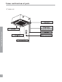
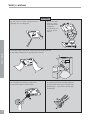
USER'S MANUAL
FREE COMBI SERIES
CASSETTE UNITS
FC-C12AI, FC-C18AI
CONTENTS
Safety cautions
Remote control operation procedure
Optimum operation
Trouble shooting
1
2
4
13
14
Care and maintenance
18
Installation notes
21
Installation accessories and drawings
22
Indoor unit installation
24
Test and check items after installation
34
Thank you for purchasing this air conditioner.Please read this MANUAL carefully before using this unit and then
keep it properly for future reference.
CONTENTS
Installation
Operation procedure
Names and functions of parts
Names and functions of parts
Names and functions of parts
Indoor unit
1
Safety cautions
Read the following instructions carefully before use.
Avoid direct air flow to your body and avoid
excessive heating or cooling that may makes
you feel uncomfortable and do harm to your
health.
Check whether the installed stand is still firm
enough after the unit has operated for a long
time.
If a worn-out stand is left unfixed,the unit may
topple and do harm to others.
Do not remove protection grill nets from the
outdoor unit.
Do not put hands or insert anything into the
air outlet vent of the unit.
Do not stand on the outdoor
unit or put anything on it, or
you may fall down or people
may get hurt by the falling
things.
If there is something abnormal (eg.burning
smell), cut off the power immeditely and contact service center.
Do not spray any paint or
pesticide on the unit, or it
may cause fire.
If room air is stuffy, air the room by opening
door and window for a while, but please close
the curtains when operating the unit to prevent
conditioned air from leaking.
Never use wrong ampere rating fire.
Use of iron wire or copper wire may
cause the unit to break down or
cause fire.
Safety cautions
Warning
2
Safety cautions
Warning
Do not check or repair during the unit is
operating. It is very dangerous.
Do not use other
heating equipment near the air
conditioner.
It will affect the
cooling performance.
Safety cautions
Never place objects near the air intake and the air outlet of the unit.
It may affect performance or stop operation of the unit.
Do not splash water directly to indoor unit
It may cause trouble or electric shock.
3
Do not throw the remote controller and do not
press the button of the remote controller with
pointed object, or the remote controller may
be damaged.
Remote control operation procedure
Name and Function-Remote control
Note:
Be sure that there are no obstructions.
Don’t drop or throw the remote controller.
Don’t place the remote controller directly in the sunlight.
SWING button
When it is pressed, the louvers
start to rotate automatically and
stop when repressed.
FAN button
TEMP.button
by
SET TEMP. increases 1
pressing button once,and decreases
1
by pressing button once.
At COOL mode operation, SET
TEMP. can be selected from 16 to
30 .
At DRY mode operation, SET TEMP.
can be selected from 16 to 30 .
At HEAT mode operation, SET
TEMP. can be selected from 16 to
30 .
“
“
“
“
” COOL mode
” DRY mode
” FAN mode
” HEAT mode
Remote control operation procedure
Press this button to
change the fan speed of:
ON/OFF button
Press this button to turn on
or turn off the unit.
MODE button
press this button to change the
operation mode in order of:
AUTO
ON/OFF
Note:
Cooling only type have no
“
” mode.
4
Remote control operation procedure
Name and F unction-R emote contr ol. (R emove the cover )
Note: This type of r emote contr oller is a k ind of new cur r ent one. Some buttons of it that
are not available to this air conditioner will not be introduced below.
Remote control operation procedure
L iquid crystal displayer. I t
shows all set contents.
SL E E P button
Press this button to set
SL E E P operation.
T I M E R OF F button
A t operating, press T I ME R
OFF button, set OFF T I ME
in range of 0 to 24 hour to
stop the unit automatically.
ON/OFF
T I M E R ON button
A t stopping, press T I M E R
ON button, set ON T IME in
range of 0 to 24 hour to start
the unit automatically.
5
Remote control operation procedure
C OOL mode operation procedure
A ccor ding to differ ence between r oom temp. and set temp., micr ocomputer can contr ol cooling
on or not.
I f r oom temp. is higher than set temp., compr essor r uns at C OOL mode.
I f room temp. is lower than set temp., compr essor stops and only indoor fan motor r uns.
Set T E M P. should be in r ange of 16
to 30
Remote control operation procedure
4.Press F A N button, set
fan speed.
3.Press SW I NG button,
the louvers start to rotate automatically, and
stop when repress.
5.Press T E M P . button, set sui tabl e
T E MP.
2.Press M ODE button,
set
operation
mode.
ON/OFF
1.Plug in, press ON/OFF button,
then air conditioner is turned on.
6
Remote control operation procedure
HEAT mode operation procedure
I f r oom temp. is lower than set temp., compr essor r uns at H E A T mode.
I f r oom temp. is higher than set temp., compr essor and outdoor fan motor stop, only indoor fan
motor runs.
Set T E M P. should be in r ange of 16
to 30
Remote control operation procedure
3.Press SW I NG button, the
louvers start to rotate
automatically, and stop
when repress it.
4.Press FA N button, set
fan speed.
5.Press T E M P. button, set suitable
T E MP.
1.Plug in, press ON/OFF button,
then air conditioner is turned on.
ON/OFF
2.Press M ODE button,
set
operation
mode.
7
Remote control operation procedure
DRY mode operation procedure
If room temp. is lower than set temp., compressor ,outdoor fan motors stop,indoor fan motors
run at low speed. I f r oom temp. is between 2 of set temp., A ir conditioner is dr ying.I f r oom
temp. is higher than set temp., it’s at C OOL mode.
Set T E M P. should be in r ange of 16 to 30
Remote control operation procedure
3.Press SW I NG button,
the louvers start to rotate automatically, and
stop when repress it.
4.Press T E M P.button,set
suitable T E M P.
2.Press M ODE button,set
operation mode.
ON/OFF
1.Plug in,press ON/OFF button,
then air conditioner is turned on.
8
Remote control operation procedure
AUTO mode operation procedure
for C O O L mode and 20
Remote control operation procedure
A t A UT O mode oper ation, standar d T E M P. is 25
mode.
ON/OFF
1.Plug in,Press ON/OFF button, then air conditioner is turned on.
2.According to room temp.,microcomputer can automatically set
operation
mode,so as for best effect.
9
for H E A T
Remote control operation procedure
A t stopping,press T I M E R
ON button, set ON T I M E
in range of 0 to 24 hour to
start the unit automatically.
ON/OFF
Remote control operation procedure
TIMER mode operation procedure
A t operating,press T I M E R
OF F button.set OF F T I M E
in range of 0 to 24 hour to
stop the unit automatically.
10
Remote control operation procedure
SLEEP mode operation procedure
W hen the unit is cooling or dr ying, if SL E E P operation is set, T E M P. would incr ease 1
hour and 2 in 2 hour s. I ndoor fan motor r uns at low speed.
W hen the unit is heating , if SL E E P oper ation is set, T E M P. would decrease 1
2 in 2 hour s.
in 1
in 1 hour and
Remote control operation procedure
4.Press F A N button, set
fan speed.
3.Press SW I NG button,
the louvers start to rotate
automatically, and stop
when repress.
6.SL E E P button
Press it to set SL E E P
operation.
5.Press T E M P . button, set suitable
T E MP.
2.Press M O DE button,
set
or
operation mode.
ON/OFF
1.Plug in, press ON/OFF button,
then air conditioner is turned on.
11
Remote control operation procedure
How to insert batteries
Note:
Don’t confuse the new and
worn or different types of
batteries.
Remove batteries when the
remote control is not in use
for a longtime.
2 Insert the AAA dry - cell batteries.
Remote control operation procedure
1. Remove the cover from the back
of the remote control.
2. Insert the two batteries ( Two AAA
dry - cell batteries ) and press ACL.
3. Re - attach the cover.
1 Remove the cover
3 Re - attach the cover.
12
Optimum operation
Adjust the room temperature properly
Adjust the room temperature properly for a comfortable
environment.
Never place anything under the indoor unit that is to be kept dry.
Water may drop from the indoor unit when the humidity
is over 80% or when the drainage outlet is clogged.
Optimum operation
Turn off the main power supply swittch when it is not to be used for long periods of time
When the main power switch is truned on, some watts of
electricity is being used even if the system is not operating.
Turn off the main power supply switch to save energy.
Do not open the doors and windows for a long time when air conditioner is operating
Cooling and heating performance will be affected if the
doors and windows are open for a long time.
Place TV, radio, stereo, etc. at least 1m away from the indoor unit and the remote controller.
It may cause interference in the picture or sound.
Avoid direct air flow to pets and plants.
It may do harm to them.
13
Trouble shooting
Warning
* In case of something abnormal (such as bad smell), shut off the power switch immediately and contact service center.
* Do not repair the air conditioner by yourself. Because wrong repair may cause fire, please contact service center.
* the appliance should not be used by children without supervision.
Check these items shown below before contacting service center.
Corrective Measures
The system does not
Pause off or fuse broken
Change fause or replace fuse
operate at all
Power off
It will restart when power is on
Loose plug
Put the plug into place
Batteries of remote controller fall
Replace batteries
Out of the remote controlling range
Keep distance in 8m or less
The system stops right
Object at the air intake and
Remove them
after it is started
air outlet of the air conditioner
Cooling and heating is
Object at the air intake and
melfunctioning
air outlet of indoor and out door units
Trouble shooting
Cause
Phenomenon
Remove them
Wrong temperature setting
Refer to p6
Low fan speed
Refer to p6
Air direction is not correct
Refer to p6
Doors or windows are open
Close them
Direct sunshine
Close the curtain or blinber
Too many people in the room
Too many heating sources
Dirty air filter
Clean it
Note:
If trouble still exists after checking the about items,please contact service center.
14
Trouble shooting
The following are not troubles
“Trouble”
Cause
The unit does not
Restart right after stopping
Once the unit is stopped, it will not operate
operate when
Press SET TEMP. and then release immediately.
for about 3 minutes to protect it
Power is switched on
Wati for 1 minute
When cooling
Room air is chilled rapidly and becomes
Mist is emitted
foggy.
Outdoor unit is hot
after the unit is stopped
Compressor is emitting heat to get ready
for restarting.
Noise
Buzz is heard at starting
It’s the starting sound of thermostat and
Trouble shooting
will turn low after 1 minute.
Sound of running water can be heard
This is caused by the refrigerant flowing
during operation
inside the unit
A “shuh” sound which is heard at the start
This is the noise of refrigerant caused by
or immediately after the stop of operation
flow stop and flow change.
or which is heard at the start or immediately The noise is heard when the drainage pump
after the stop of defrosting operation.
is in operation.
A continuous low “shah” sound is heard
when the system is in cooling operation or
at a stop.
This is caused by the panel expanding or
Dust from the units
Cracking noise can be heard during or after
contracting due to the change in
operation.
temperature.
Starting operation after not using for a long
Dust absorbed by the unit blows out
time.
Wind from the outlet
smells
15
During operation
This is caused by the odors in the room
which have gotten onto the air conditioner
Trouble shooting
FAULT INDICATION
NO.
1
2
3
Meaning
Compressor high pressure
protection unit stop
Indoor unit anti-freezing
protection
Low-pressure protection
unit stop
LED
(red)
LED
(yellow)
LED
(green)
Blink once
Twice times
Three times
7
Unit modes conflict
Seven times
8
Jumper
Fifteen times
9
Defrosting/Heating oil return
Blink once
10
Compressor overload protection
unit stop
Three times
11
System Unit
Four times
12
IPM modular protection unit
stop
Five times
13
PFC protection unit stop
Six times
14
Compressor malfunction
Seven times
15
Water spill protection
Eight times
16
Three times
20
Indoor ambient temp. sensor
malfunction
Indoor pipe temp. sensor
malfunction
Outdoor ambient temp. sensor
malfunction
Outdoor pipe temp. sensor
malfunction
Outdoor air exhaust temp.sensor
malfunction
21
E2 PROM Error
Eleven times
22
Wire controller ambient temp.
sensor malfunction
5
17
18
19
malfunction
malfunction
Trouble shooting
6
Air exhaust protection unit stop Four times
Over current protection unit
Five times
stop
Communication malfunction unit
Six times
stop
4
Blink once
Twice times
Four times
Five times
Blink once
16
Trouble shooting
When the unit is running operated by wire controller.
The Codes of Failure Definitions are as Follows:
Trouble shooting
NO.
17
Meaning
Fault code
1
Compressor high pressure protection unit stop
E1
2
Indoor unit anti-freezing protection
E2
3
Low-pressure protection unit stop
E3
4
Air exhaust protection unit stop
E4
5
Over current protection unit stop
E5
6
Communication malfunction unit stop
E6
7
Unit modes conflict
E3
8
Jumper malfunction
E3
9
Defrosting /Heating oil return
10
Compressor overload protection unit stop
E5
11
System Unit malfunction
F2
12
IPM modular protection unit stop
E5
13
PFC protection unit stop
E5
14
Compressor malfunction
E9
15
Water spill protection
E9
16
Indoor ambient temp. sensor malfunction
F0
17
Indoor pipe temp. sensor malfunction
F1
18
Outdoor ambient temp. sensor malfunction
F3
19
Outdoor pipe temp. sensor malfunction
F2
20
Outdoor air exhaust temp. sensor malfunction
F4
21
E2 PROM Error
E3
22
Wire controller ambient temp. sensor malfunction
F5
defrost
Care and maintenance
Please pull out the power plug after you used the air conditioner.
Warning
Pull out the power plug before cleaning
Do not splash water directly to the unit
How to clean the air filter
2.Remove the air filters.
Slide knobs on the back of the suction grille
outward and remove the air filter.
Then romove three air cleaners on it.
Care and maintenance
1.Open the suction grille
Use screwdriver screws the two screws.
Slide both knobs simultaneously as shown and
then pull them downward slowly.
3.Clean the air filter
Use vacuum or wash the air filter with water when
the air filter is very dirty,use neutral detergent and
water.Let the filter dry naturally at shady place.
Note:
Do not clean with hot water
Do not dry over fire
Do not run the air conditioner without the air filter.
T he suction grille must be opened by skilled personnel.
18
Care and maintenance
4.Fix the air filters
Replace the air filter into its holder.
Make sure that the air filter makes contact with the
filter stopper when it is replaced into its holder.
Care and maintenance
Shut the suction grille.
Refer to step 1.
How to clean the suction grille
1.Open the suection grille.
See step 1 of “How to clean the air filter”
2.Remove the air filters.
See step 2 of “How to clean the air filter”
3.Remove the suction grille
Open the suction grille at 45 and then lift.
4.Wash with water.
When the suction grille is very dirty,use soft
brush and neutral detergent.Shake off water and
dry in a shady place.
Notes:Do not wash with hot water.
19
5.Fix the suction grille
Refer to step 3.
6.Fix the air filter.
See step 4 of “How to clean the air filter”
7.Close the suction grille
Refer to step 1.
Care and maintenance
Before starting the air conditioner for the first time in the season
1.Check to make sure no objects obstructing the intake
and outlets parts on both the indoor and outdoor units.
2.Check to make sure ground wire is connected and
that it is not damaged.
3.Check to make sure air filter has been cleaned.
4.Turn on the power 6 hours before starting the air
conditioner.
1.Clean the filter and the body of the unit.
2.Turn off power.
3.Clear outdoor unit of dust.
4.If there is any rust in the outdoor unit, this should be
painted over to prevent the rust from spreading.
Power supply and wiring requirement
Care and maintenance
End of seaseon cleaning
1. Power frequency of air-conditioner should be 50Hz, voltage:
AC 220-240V.
If voltage are over may cause the parts of electric equipment damaged. If the voltage are too low may cause shake
on compressor, it may let the cooling system damaged, and also, the compressor and parts will not work. Voltage
should be stable, which cannot have a big fluctuation.
2. User power supply should be provided a reliable earthing connect. (see earth requirement)
Electric connection requirement
1. Should have a reliable earth connection (see earth connection requirement)
2. Screw of wire should be tight, damaged screw should be changed. Self-tapping screw cannot use on electric
connection.)
3. Wire should be used by the provided one. Please do not change the wire, length and the end of it. If you need to
adjust, please contact with the local service center.
4. Please do not connect the plug with the non-plug wire by yourself.
5. Indoor and outdoor electrical connecting wire should not affect by elasticity and twist.
20
Installation notes
L ocation
T he air conditioner must be firmly installed and 3 4
liability checks must be done every year.
A void place whthin easy reach of young children.
Avoid other heat sources or direct sun light.
Install indoor unit away from T V set or radio.
A void where inflammable gas is likely to leak.
At salty coastal areas or special areas such as the vicinity
of a sulphurous hot spring,please contact dealer before
installation to make sure it is safe to use the unit.
Not to be installed in laundries.
T he air conditioner must be positioned so trat the plug
is accessible.
Noise
Select a place with good ventilation or it may affect
performance or increase noise.
I nstall the air conditioner on a foundation that can
withstand its weight.insufficient strength may result in
the fall of equipment and cause injury.
Select a place so as not to annoy neighbor with the hot
air or noise.
Never place objects near the air outlet or the unit,it may
affect performance or increase noise.
If there is abnormal noise during the operating,contact
dealer immediately.
Installation and transportation
I nstallation notes
Installation and transportation of the unit must be done
by skilled personnel.
B e sure to use only the specified accessories and parts
for installation,failure to use may lead to electric shock,
leakage or fire.
Carry out installation with consideration of strong winds,
typhoons,or earthquakes.Improper installation work may
result in accidents due to fall of equipment.
If the unit is to be moved to other place,please consult
dealer first.
E arthing requirement
21
Wiring arrangement
Make sure wiring is carried out by qualified personnel
according to laws and regulations and this manual,using
a separate circuit and suitable fuse.
B e sure to install an earth leakage breaker.
Diameter of power supply cord must be big enough.
(R efer to P24 about the sizes of diameter)
If the supply cord is damaged, it must be replaced by the
manufacturer or its service agent or a similarly qualified
person in order to avoid a hazard.
T he appliance shall be installed in accordance with
relative wiring regulations.
1. A ir-conditioner is the class I appliance, it must be use the suitable earthing connection.
2. Please do not cut or change the method of use of the yellow / green earthing wire of the
air-conditioner. Otherwise, it may cause the electrical leakage.
3. E arthing resistance should be approved by Country Standard GB 17790.
4. User power should be provided a reliable earthing terminal. Please do not let the earthing
wire to connect the following place:
1. Water supply
3. Sewage tube
2. Gas supply
4. Some places there are not reliable by a professional.
W ater pipe
G as pipe
Some parts of the water pipe are made of plastic
materials and not suitable for earthing.
I f there is electrical leakage accidently from air
conditioner,it is easy to cause fire or explosion.
Installation accessories and drawings
Accessories
Name
1
Shape
Quantity
Notes
Drainage hose
1
For indoor side pipe joint
2
Clamp
1
For hole
3
Nylon fastener
4
L=200
4
Washer
10
10
5
Paper pad for installaition
1
6
Screws
4
7
Heat preservation Sponge for pipe
2
8
Big sealing pad
1
5
160
300
9
Sealing pad
1
5
45
300
10
Small sealing pad
2
3
30
150
11
Sealing bar
1
120
12
PVC tape
2
13
Screws
8
14
Remote controller
1
15
Battery
2
16
Power control wire
ST4.8
13-F
Use for Paper pad for
installation
Encase the tie-in
ST4.2
65
25
9.5PA
For mounting the remote
control unit
AAA 1.5V
Installation accessories and drawings
No.
For remote control
1
22
Installation drawings
Installation drawings
Installation drawings
Indoor unit
Fig.1
Note:
Air conditioner must be installed by skilled personnel according to this manual.
23
Indoor unit installation
Location
1.Do not place object near the air oulet so that conditioned air can reach the whole room.
2.Be sure to install the indoor unit firmly and horizontly.
3.Select the place that can support 4 times of the indoor unit’s weight and will not increase noise and vibration.
4.Select a place easy to drain water and connect with the outdoor unit.
5.Make sure there is enough space for maintenance and make sure the distance between the unit and ground is 1.8m
or more.
6.Make sure the suspension bolt pitch can hold 4 times of the indoor units’s weight,otherwise,you should strengthen
the suspension bolt pitch.
Note:
1.Keep enough distance from the kitchen.
2.The appliance shall not installed in the lundary.
Fig.2
Fig.3
Indoor unit installation
Ceiling opening and suspension bolt (M10) pitch demension.
Hanging preparations
Firmly fasten the hanging bolts as shown in Fig.4 or by another method.
24
Indoor unit installation
Fig.5
Hanging preparations
Indoor unit installation
(1) Install special nut A, then special nut B onto the hanging bolt. (Fig.6)
(2) Raise the body and mount its hooks onto the hanging bolt between the special nuts. (Fig.6)
(3) Turn special nut B to adjust the height of the body. (Fig.6)
(4) Leveling a level, or vinyl hose filled with water, fine adjust so that the body is level.
Warning
Perform final tightening by tightening the double nut firmly.
Fig.6
25
Indoor unit installation
Fig.7
Vinyt hose
NOTE: Install the drain pipe.
Install be drain pipe with downward gradient (1/50 to 1/100) and so there are no rises or traps in the pipe.
Use general hard polyvinyl chloride pipe (VP25) [outside diameter 1-1/4” (32mm)] and connect it with adhesive
(polyvinyl chloride) so that there is no leakage.
When the pipe is long, install supporters.
Always heat insulate the indoor side of the drain pipe.
When desiring a high drain pipe height, raise it up to 15” (400 mm) or less from the ceiling within a range of 6”
(150mm) from the body. Arise dimension over this range will cause leakage.
Indoor unit installation
Installing drain pipe
Fig.8
26
Indoor unit installation
Connecting the pipes
Besure to use both a spanner and wrench together as shown in the drawing during connecting or disconnecting pipes
to/from the unit.
The pipe of water-in/out is pipe thread G3/4.The surface of thread should be enlaced by the two or three-circles trap.
After the water-in pipe and water-out pipe is connecting tightly,starting the water pump,then checking it’s airproof
performance.
Insulate it as shown in the drawing below.
Use sealing pad (10) to wrap the water-in/out pipe and the insulation (8).
Fig.9
Indoor unit installation
Socket wrench
Torque wrench
Fig.10
Medium sponge
(wrap the joint with the sealing pad)
Wire clamp (X4)
Insulation for fitting
(attached
Water-in pipe
Water-out pipe
27
)
Indoor unit installation
Electrical wiring
How to connect wiring to the terminals
A. For solid core wiring (or F-cable)
(1) Cut the wire end with a wire cutter or wire-cutting pliers, then stuip the insulation to about 15/16” (25mm) of expose
the solid wire.
(2) Using a screwdriver,remove the terminal screw (s) on the terminal board.
(3) Using pliers, bend the solid wire to form a loop suitable for the terminal screw.
(4) Shape the loop wire properly, place it on the terminal board and tighten securely with the terminal screw using a
screw driver.
B. For strand wiring
(1) Cut the wire end with a wire cutter or wire-cutting pliers, then strip the insulation to about 3/8” (10mm) of expose
(2) Using a screwdriver, remove the terminal screw (s) on the terminal board.
(3) Using a round terminal fastener or pliers, securely clamp a round terminal to each stripped wire end.
(4) Position the round terminal wire, and replace and tighten the terminal screw using a screwdriver.
C. Attention:
An all-pole disconnection switch having a contact separation of at least 3mm in all poles should be connected in
fixed wiring.
Fig.11
B. Strand wire
Loop
Insulation
Strip 3/8” (10 mm)
Strip 15/16” (25 mm)
A. Solid wire
Indoor unit installation
the solid wire.
Round
terminal
Screw with
special washer
Round
terminal
Wire
Terminal
board
Screw with
special washer
Round
terminal
Wire
28
Indoor unit installation
Indoor unit side
Remove the control box cover and install the connection cord. (Fig. 12 and 13)
Fig.12
Control box cover
Fig.13
Indoor unit installation
Note
N(1)
* The temperature of refrigerant circuit will be high, please keep the
interconnection cable away from the copper tube.
3
Black Brown
* An all-pole disconnection device which has at least 3mm separation
distance in all pole and a residual current device(RCD)with the rating
of above 10mA shall be incorporated in the fixed wiring according to
the national rule.
Circuit Diagram
FC-C12AI
FC-C18AI
29
Blue
2
4-core rubber cable
(to outdoor unit)
Yellow/Green
Indoor unit installation
Bolting the grille assembly to the body
Install the grille assembly to the body with the four bolts,spring washers,and washers.
Fig.14
Washer
Spring washer
No gap between ceiling and
grille around entire periphery.
Wireless unit connection wire wiring
(1). Connect the connector in accorbance part A detail view.
(2). Then clamp the lead wire with clamp so that it does not touch the rotating parts.
Indoor unit installation
Bolt
Fig.15
30
Indoor unit installation
Fig.16
Part A detail view
Installing/Removing the intake grille
1. Installing the intake grille
Indoor unit installation
(1) Full insert the intake grille hooks into the rectangular holes in the panel.
Fig.17
(2) Close the intake grille,then slide the tow grille stoppers outward.
Fig.18
31
Indoor unit installation
2.Removing the intake grille
(1) Slide the two grille stoppers inward,and then open the iotake grill.
Fig.19
Grille stopper
(2) Remove the geille hook screws, and then open the intake grille.
Grille hook
Indoor unit installation
Fig.20
(3) Open the intake grille so that it is at an angle of 20° to 40° ,and then remove the grille.
Fig.21
Caution:
(1)the louver angle cannot be changed if the power is not no, (It moved by hand,ir may be damaged.)
(2) The grille assembly is directional relative to the air conditioner body.
(3) Install so that there is no gap between the grille assembly and the air conditioner body.
32
Indoor unit installation
Connection of refrigerant pipe
Besure to use both a spanner and torque wrench together as shown in the drawing,connecting or disconnecting pipes
to/from the unit.
Refer to table 1 to determine the proper tightening torque (over tightening may damage the flare and cause leaks.)
When conecting the flare nut,coat the flare both inside and outside with refrigerating machine oil and initially
tighten by hand 3 or 4 turns.
Check the pipe connector for gas leaks,then insulate it as shown in the drawing below.
Use sealing pad (11) to wrap joint between gas pipe and the insulation(8).
The enclosure of the appliance shall be marked by word, or by symbols, with the direction of the fluid flow.
Fig.22
Tightening torque table:
Pipe gauge
Ф6
Ф 9.52
Ф 12
33
Tightening torque(N·m)
15~20
30~40
50~55
Test and check items after installation
1. Prepare for test
(1) Do not turn on the power switch before all installation is finsihed.
(2) Connect wires corectly and firmly.
(3) Open the check valve.
(4) Remove all dust.
2. Testing
(1) Turn on the power switch and press “ON/OFF” button.
(2) Press “MODE” button to select COOL,HEAT,FAN,etc to test whether it
operates mormally.
3.Emergency operation.
When the batteries fail or when the remote controller is missing,operate as
shown below.
* When stop, you can press the “AUTO” button on cover NO.
then unitl is in “AUTO” mode.
The air conditioner selects COOL,HEAT,DRY,FAN
modes automatically.
When
operating,press the “AUTO” button,the air conditioner will stop.
*
Note
The “TEST” button on the cover No. is specially for testing the air conditioner.
When pressing it,the air conditioner will be forced to operate or stop.Do not press
it when air conditioner is in normal operation.
For the following items,take special care during construction and check after installation is finished.
Items to check
If not properly done,what is likely to happen
Is the indoor unit fixed firmly?
The unit may drop,vibrate or make noise.
Is the gas leak test finished?
It may result in insufficient cooling.
Is the unit fully insulated?
Condensate water may drip.
Does drainage flow smoothly?
Condensate water may drip.
Does the power supply voltage correspond to
The unit may malfunction or the components burn
that shown on the nameplate
out.
Check
Test and check items after installation
Test operation
The unit may malfunction or the components burn
Are wiring and piping correct?
Is the unit safely grounded?
out.
Risk of electric leakage.
The unit may malfunction or the components burn
Is wiring size according to specifications?
out.
Is something blocking the air outlet or intake
of either the indoor or outdoor units?
It may result insufficient cooling.
Have records of refrigerant piping length and
Volume of refrigerant charge in the system is not
additional refrigerant charge been made?
clear.
Note to the installer
Be sure to instruct the customer how to operate the system and show him/her the attached operation manual.
34