1
IFS WMC303-1W-1T-1200
Dual Band Wireless Access Point
User Manual
P/N 1073050 • REV A • ISS 15OCT15
Copyright
© 2015 United Technologies Corporation
Interlogix is part of UTC Building & Industrial Systems, Inc. a unit of United
Technologies Corporation. All rights reserved.
Trademarks and
patents
The WMC303-1W-1T-1200 name and logo are trademarks of United
Technologies.
Other trade names used in this document may be trademarks or registered
trademarks of the manufacturers or vendors of the respective products.
Manufacturer
Interlogix ( UTC Fire and Security)
3211 Progress Drive, Lincolnton, NC 28092 USA
Authorized EU manufacturing representative:
UTC Climate Controls & Security B.V.,
Kelvinstraat 7, 6003 DH Weert, Netherlands
Intended use
Use this product only for the purpose it was designed for; refer to the data sheet
and user documentation for details. For the latest product information, contact
your local supplier or visit us online at www.interlogix.com.
Certification
N4131
ACMA compliance
European Union
directives
Notice! This is a Class B product. In a domestic environment this product may
cause radio interference in which case the user may be required to take
adequate measures.
2004/108/EC (EMC Directive): Hereby, UTC Building & Industrial Systems, Inc.
declares that this device is in compliance with the essential requirements and
other relevant provisions of Directive 2004/108/EC.
Federal Communication Commission Interference Statement
This equipment has been tested and found to comply with the limits for a Class B digital device,
pursuant to part 15 of the FCC Rules. These limits are designed to provide reasonable
protection against harmful interference when the equipment is operated in a commercial
environment. This equipment generates, uses, and can radiate radio frequency energy and, if not
installed and used in accordance with the instruction manual, may cause harmful interference to
radio communications. Operation of this equipment in a residential area is likely to cause harmful
interference in which case the user will be required to correct the interference at his/her own
expense. Any changes or modifications not expressly approved by UTC could void the user’s
authority to operate this equipment under the rules and regulations of the FCC.
FCC Caution:
To assure continued compliance, (for example, use only shielded interface cables when connecting
to computer or peripheral devices) any changes or modifications not expressly approved by the party
responsible for compliance could void the user’s authority to operate the equipment.
This device complies with Part 15 of the FCC Rules. Operation is subject to the following two
conditions:
(1) This device may not cause harmful interference
(2) This device must accept any interference received, including interference that may cause
undesired operation.
II
Federal Communication Commission (FCC) Radiation Exposure Statement
This equipment complies with FCC radiation exposure set forth for an uncontrolled environment. In
order to avoid the possibility of exceeding the FCC radio frequency exposure limits, human proximity
to the antenna shall not be less than 20 cm (8 inches) during normal operation.
CAUTION: Changes or modifications not expressly approved by UTC for compliance could void the
user’s authority to operate the equipment.
CE Mark Warning
This is a Class B product. In a domestic environment, this product may cause radio interference, in
which case the user may be required to take adequate measures.
Energy Saving Note of the Device
This power required device does not support Standby mode operation. For energy saving, please
remove the DC-plug to disconnect the device from the power circuit. Without removing the DC-plug,
the device still consumes power from the power circuit. In view of Saving the Energy, it is strongly
suggested to remove the DC-plug for the device if this device is not intended to be active.
Canadian Compliance
This Class B digital apparatus meets all requirements of the Canadian Interference Causing
Equipment Regulations. Cet appareil numérique de la classe B respects toutes les exigences du
Règlement sur le matériel brouilleur du Canada.
Canada - Industry Canada (IC)
The wireless radio of this device complies with RSS 247 and RSS 102 of Industry Canada.
This Class B digital device complies with Canadian ICES-003 (NMB-003).
Cet appareil numérique de la classe B respects toutes les exigences du Règlement sur le matériel
brouilleur du Canada.
This device complies with Industry Canada’s licence-exempt RSSs. Operation is subject to the
following two conditions:
(1) This device may not cause interference; and
(2) This device must accept any interference, including interference that may cause undesired
operation of the device.
Le présent appareil est conforme aux CNR d'Industrie Canada applicables aux appareils radio
exempts de licence. L'exploitation est autorisée aux deux conditions suivantes :
(1) l'appareil ne doit pas produire de brouillage, et
(2) l'utilisateur de l'appareil doit accepter tout brouillage radioélectrique subi, même si le brouillage est
susceptible d'en compromettre le fonctionnement.
WMC303-1W-1T-1200 complies with IC requirements, IC: 20201-WMC3031200.
III
This radio transmitter (IC: 20201-WMC3031200) has been approved by Industry Canada to operate
with the antenna types listed below with the maximum permissible gain indicated. Antenna types not
included in this list, having a gain greater than the maximum gain indicated for that type, are strictly
prohibited for use with this device.
Dual Built-in the PCBA (2 x 2.4GHz 2.5dBi PCBA antenna)
Dual Built-in the PCBA (2 x 5GHz 4dBi PCBA antenna)
Le présent émetteur radio (IC: 20201-WMC3031200) a été approuvé par Industrie Canada pour
fonctionner avec les types d'antenne énumérés ci-dessous et ayant un gain admissible maximal et
l'impédance requise pour chaque type d'antenne. Les types d'antenne non inclus dans cette liste, ou
dont le gain est supérieur au gain maximal indiqué, sont strictement interdits pour l'exploitation de
l'émetteur.
Intégré 2.5dBi antenne double polarisation X 2
Intégré 4dBi antenne double polarisation X 2
LE-LAN devices shall contain instructions related to the restrictions mentioned in the above sections,
namely that:
1. the device for operation in the band 5150–5250 MHz is only for indoor use to reduce the
potential for harmful interference to co-channel mobile satellite systems;
2. for devices with detachable antenna(s), the maximum antenna gain permitted for devices in the
bands 5250-5350 MHz and 5470-5725 MHz shall be such that the equipment still complies with
the e.i.r.p. limit;
3. for devices with detachable antenna(s), the maximum antenna gain permitted for devices in the
band 5725-5850 MHz shall be such that the equipment still complies with the e.i.r.p. limits
specified for point-to-point and non-point-to-point operation as appropriate; and
4. the worst-case tilt angle(s) necessary to remain compliant with the e.i.r.p. elevation mask
requirement set forth in Section 6.2.2(3) of RSS-247 shall be clearly indicated.
The maximum conducted output power shall not exceed 250 mW or 11 + 10 log10B, dBm, whichever is
less. The power spectral density shall not exceed 11 dBm in any 1.0 MHz band.
The maximum e.i.r.p. shall not exceed 1.0 W or 17 + 10 log10B, dBm, whichever is less. B is the 99%
emission bandwidth in megahertz. Note that devices with a maximum e.i.r.p. greater than 500 mW shall
implement TPC in order to have the capability to operate at least 6 dB below the maximum permitted
e.i.r.p. of 1 W.
2) Unwanted emission limits
i) For devices with both operating frequencies and channel bandwidths contained within the band
5250-5350 MHz, the device shall comply with the following:
a. All emissions outside the band 5250-5350 MHz shall not exceed -27 dBm/MHz e.i.r.p. if the
equipment is intended for outdoor use; or
IV
b. All emissions outside the band 5150-5350 MHz shall not exceed -27 dBm/MHz e.i.r.p. and any
emissions within the band 5150-5250 MHz shall meet the power spectral density limits of
Section 6.2.1 of RSS-247. The device shall be labelled “for indoor use only.”
ii) For devices with operating frequencies in the band 5250-5350 MHz but having a channel bandwidth
that overlaps the band 5150-5250 MHz, the devices’ unwanted emission shall not exceed
-27 dBm/MHz e.i.r.p. outside the band 5150-5350 MHz and its power shall comply with the spectral
power density for operation within the band 5150-5250 MHz. The device shall be labelled “for indoor
use only.”
3) Additional requirements
In addition to the above requirements, devices operating in the band 5250-5350 MHz with a maximum
e.i.r.p. greater than 200 mW shall comply with the following e.i.r.p. at different elevations, where θ is the
angle above the local horizontal plane (of the Earth) as shown below:
1.
2.
3.
4.
-13 dBW/MHz for 0° ≤ θ < 8°
-13 − 0.716 (θ-8) dBW/MHz for 8° ≤ θ < 40°
-35.9 − 1.22 (θ-40) dBW/MHz for 40° ≤ θ ≤ 45°
-42 dBW/MHz for θ > 45°
The measurement procedure defined in Annex A of RSS-247 shall be used to verify the compliance to
the e.i.r.p. at different elevations.
Users should also be advised that high-power radars are allocated as primary users (i.e. priority users)
of the bands 5250-5350 MHz and 5650-5850 MHz and that these radars could cause interference
and/or damage to LE-LAN devices.
Digital Transmission Systems (DTSs)
DTSs include systems that employ digital modulation techniques resulting in spectral characteristics
similar to direct sequence systems. The following applies to the bands 902-928 MHz and 2400-2483.5
MHz.
(1) The minimum 6 dB bandwidth shall be 500 kHz.
(2) The transmitter power spectral density conducted from the transmitter to the antenna shall not be
greater than 8 dBm in any 3 kHz band during any time interval of continuous transmission. This power
spectral density shall be determined in accordance with the provisions of Section 5.4(4), (i.e. the power
spectral density shall be determined using the same method as is used to determine the conducted
output power).
For DTSs employing digital modulation techniques operating in the bands 902-928 MHz and
2400-2483.5 MHz, the maximum peak conducted output power shall not exceed 1W. Except as
provided in Section 5.4(5), the e.i.r.p. shall not exceed 4 W.
As an alternative to a peak power measurement, compliance can be based on a measurement of the
maximum conducted output power. The maximum conducted output power is the total transmit power
delivered to all antennas and antenna elements, averaged across all symbols in the signalling alphabet
when the transmitter is operating at its maximum power control level. Power must be summed across
all antennas and antenna elements. The average must not include any time intervals during which the
transmitter is off or transmitting at a reduced power level. If multiple modes of operation are
V
implemented, the maximum conducted output power is the highest total transmit power occurring in
any mode.
(5) Fixed point-to-point systems in the bands 2400-2483.5 MHz and 5725-5850 MHz are permitted to
have an e.i.r.p. higher than 4 W provided that the higher e.i.r.p. is achieved by employing higher gain
directional antennas and not higher transmitter output powers. Point-to-multipoint systems,2
omnidirectional applications and multiple co-located transmitters transmitting the same information are
prohibited from exceeding an e.i.r.p. of 4 W.
(6) Transmitters may operate in the band 2400-2483.5 MHz, employing antenna systems that emit
multiple directional beams simultaneously or sequentially, for the purpose of directing signals to
individual receivers or to groups of receivers, provided that the emissions comply with the following:
(i) Different information must be transmitted to each receiver.
(ii) If the transmitter employs an antenna system that emits multiple directional beams, but does not
emit multiple directional beams simultaneously, the total output power conducted to the array or arrays
that comprise the device (i.e. the sum of the power supplied to all antennas, antenna elements, staves,
etc., and summed across all carriers or frequency channels) shall not exceed the applicable output
power limit specified in sections 5.4(2) and 5.4(4). However, the total conducted output power shall be
reduced by 1 dB below the specified limits for each 3 dB that the directional gain of the
antenna/antenna array exceeds 6 dBi. The directional antenna gain shall be computed as the sum of
10 log (number of array elements or staves) plus the directional gain of the element or stave having the
highest gain.
(iii) If a transmitter employs an antenna that operates simultaneously on multiple directional beams
using the same or different frequency channels, the power supplied to each emission beam is subject
to the applicable power limit specified in sections 5.4(2) and 5.4(4). If transmitted beams overlap, the
power shall be reduced to ensure that their aggregate power does not exceed the applicable limit
specified in sections 5.4(2) and 5.4(4). In addition, the aggregate power transmitted simultaneously on
all beams shall not exceed the applicable limit specified in sections 5.4(2) and 5.4(4) by more than 8
dB.
(iv) Transmitters that transmit a single directional beam shall operate under the provisions of sections
5.4(2), 5.4(4) and 5.4(5).
5.5 Unwanted Emissions
In any 100 kHz bandwidth outside the frequency band in which the spread spectrum or digitally
modulated device is operating, the RF power that is produced shall be at least 20 dB below that in the
100 kHz bandwidth within the band that contains the highest level of the desired power, based on
either an RF conducted or a radiated measurement, provided that the transmitter demonstrates
compliance with the peak conducted power limits. If the transmitter complies with the conducted power
limits based on the use of root-mean-square averaging over a time interval, as permitted under Section
5.4(4), the attenuation required shall be 30 dB instead of 20 dB. Attenuation below the general field
strength limits specified in RSS-Gen is not required.
No part of this publication may be reproduced in any form or by any means or used to make any
derivative work (such as translation, transformation or adaptation) without written permission from UTC
VI
Fire and Security.
UTC, reserves the right to revise this publication and to make changes in content from time to time
without obligation on the part of UTC to provide notification of such revision or change. UTC provides
this guide without warranty of any kind, implied or expressed, including, but not limited to, the implied
warranties of merchantability and fitness for a particular purpose. UTC may make improvements or
changes in the product(s) described in this manual at any time.
CAUTION: TO ENSURE REGULATORY COMPLIANCE, USE ONLY THE PROVIDED POWER AND
INTERFACE CABLES.
CAUTION: DO NOT OPEN THE UNIT. DO NOT PERFORM ANY SERVICING OTHER THAN THAT
CONTAINED IN THE INSTALLATION AND TROUBLESHOOTING INSTRUCTIONS. REFER ALL
SERVICING TO QUALIFIED SERVICE PERSONNEL.
R&TTE Compliance Statement
This equipment complies with all the requirements of DIRECTIVE 1999/5/CE OF THE EUROPEAN
PARLIAMENT AND THE COUNCIL OF 9 March 1999 on radio equipment and telecommunication
terminal Equipment and the mutual recognition of their conformity (R&TTE). The R&TTE Directive
repeals and replaces in the directive 98/13/EEC (Telecommunications Terminal Equipment and
Satellite Earth Station Equipment) as of April 8, 2000.
Safety
This equipment is designed with the utmost care for the safety of those who install and use it.
However, special attention must be paid to the dangers of electric shock and static electricity when
working with electrical equipment. All guidelines of this and of the computer manufacture must
therefore be allowed at all times to ensure the safe use of the equipment.
Wireless LAN and your Health
The WMC303-1W-1T-1200 like other radio devices, emits radio frequency electromagnetic energy, but
operates within the guidelines found in radio frequency safety standards and recommendations.
Restrictions on Use of Wireless Devices
In some situations or environments, the use of wireless devices may be restricted by the proprietor of
the building or responsible representatives of the organization. For example, these situations may
include:
. Using wireless equipment in any environment where the risk of interference to other devices or
services is perceived or identified as harmful.
If you are uncertain of the applicable policy for the use of wireless equipment in a specific organization
or environment, you are encouraged to ask for authorization to use the device prior to turning on the
equipment.
The manufacturer is not responsible for any radio or television interference caused by unauthorized
modification of the devices included with this product, or the substitution or attachment of connecting
VII
cables and equipment other than specified by the manufacturer. Correction of interference caused by
such unauthorized modification, substitution, or attachment is the responsibility of the user.
The manufacturer and its authorized resellers or distributors are not liable for any damage or violation
of government regulations that may arise from failing to comply with these guideline documentation
that comes with the product.
Postpone router installation until there is no risk of thunderstorm or lightning activity in the area.
Do not overload outlets or extension cords, as this can result in a risk of fire or electric shock.
Overloaded AC outlets, extension cords, frayed power cords, damaged or cracked wire insulation, and
broken plugs are dangerous. They may result in a shock or fire hazard.
Route power supply cords so that they are not likely to be walked on or pinched by items placed upon
or against them. Pay particular attention to cords where they are attached to plugs and convenience
receptacles, and examine the point where they exit from the product.
Place this equipment in a location that is close enough to an electrical outlet to accommodate the
length of the power cord.
Place this equipment on a stable surface.
When using this device, basic safety precautions should always be followed to reduce the risk of fire,
electric shock and injury to persons, including the following:
. Read all of the instructions {listed here and/or in the user manual} before you operate this equipment.
Give particular attention to all safety precautions.
Retain the instructions for future reference.
. Comply with all warning and caution statements in the instructions. Observe all warning and caution
symbols that are affixed to this equipment.
. Comply with all instructions that accompany this equipment.
. Avoid using this product during an electrical storm. There may be a risk of electric shock from
lightning. For added protection for this product during a lightning storm, or when it is left unattended
and unused for long periods of time, unplug it from the wall outlet, and disconnect the cable system.
This will prevent damage to the product due to lightning and power surges. We also recommend the
use of ESP300 20Kv protection on the input at the switch or network.
. Operate this product only from the type of power source indicated on the product’s marking label. If
you are not sure of the type of power supplied to your home, consult your dealer or local power
company.
. Upon completion of any service or repairs to this product, ask the service technician to perform safety
checks to determine that the product is in safe operating condition.
It is recommended that the customer install an AC surge protector in the AC outlet to which this device
is connected. This is to avoid damaging the equipment by local lightning strikes and other electrical
surges.
Different types of cord sets may be used for connections to the main supply circuit. Use only a main
line cord that complies with all applicable product safety requirements of the country of use. Installation
VIII
of this product must be in accordance with national wiring codes.
Place unit to allow for easy access when disconnecting the power cord/adapter of the device from the
AC wall outlet.
Wipe the unit with a clean, dry cloth. Never use cleaning fluid or similar chemicals. Do not spray
cleaners directly on the unit or use forced air to remove dust.
This product was qualified under test conditions that included the use of the supplied cables between
system components. To be in compliance with regulations, the user must use these cables and install
them properly. Connect the unit to a grounding type AC wall outlet using the power adapter supplied
with the unit.
Do not cover the device, or block the airflow to the device with any other objects. Keep the device away
from excessive heat and humidity and keep the device free from vibration and dust.
Installation must at all times conform to local regulations.
National Restrictions
This device is intended for home and office use in all EU countries (and other countries following the EU
directive 1999/5/EC) without any limitation except for the countries mentioned below:
Country
Restriction
Bulgaria
None
France
Reasons/remarks
General authorization required for outdoor use and
public service
Outdoor use; limited to 10
Military Radiolocation use. Reframing of the 2.4 GHz
mW e.i.r.p. within the band
band has been ongoing in recent years to allow current
2454-2483.5 MHz
relaxed regulation. Full implementation planned 2012
Italy
None
Luxembourg
None
Norway
Implemented
Russian
None
If used outside of own premises, general authorization is
required
General authorization required for network and service
supply(not for spectrum)
This subsection does not apply for the geographical area
within a radius of 20 km from the centre of Ny-Ålesund
Only for indoor applications
Federation
Note: Please don’t use the product outdoors in France.
WEEE regulation
To avoid the potential effects on the environment and human health as a result of the
presence of hazardous substances in electrical and electronic equipment, end users of
electrical and electronic equipment should understand the meaning of the crossed-out
wheeled bin symbol. Do not dispose of WEEE as unsorted municipal waste and have to
collect such WEEE separately.
IX
Contact Information
For contact information, see www.interlogix.com or
www.utcfssecurityproducts.eu.
X
CONTENTS
Chapter 1.Product Introduction ........................................................................................................... 1
Chapter 2.Hardware Installation ........................................................................................................ 10
Chapter 3.Connecting to the AP ........................................................................................................ 12
Chapter 4.Quick Installation Guide ................................................................................................... 15
Chapter 5.Configuring the AP ............................................................................................................ 19
Chapter 6.Quick Connection to a Wireless Network ..................................................................... 101
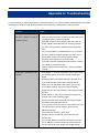
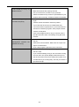
Appendix A: Troubleshooting .......................................................................................................... 112
Appendix B: Glossary....................................................................................................................... 114
XI
FIGURE
FIGURE 2-1 WMC303-1W-1T-1200 PRODUCT DRAWING ......................................................................... 10
FIGURE 2-2 WMC303-1W-1T-1200 PANEL LAYOUT ................................................................................. 11
FIGURE 3-1 WMC303-1200 INSTALLATION DIAGRAM 1 ............................................................................. 12
FIGURE 3-2 WMC303-1200 INSTALLATION DIAGRAM 2 ............................................................................. 13
FIGURE 3-3 WMC303-1200 INSTALLATION DIAGRAM 3 ............................................................................. 13
FIGURE 3-4 WMC303-1200 INSTALLATION DIAGRAM 4 ............................................................................. 14
FIGURE 3-5 WMC303-1200 INSTALLATION DIAGRAM 4 ............................................................................. 14
FIGURE 4-1 TCP/IP SETTING ................................................................................................................... 16
FIGURE 4-2 W INDOWS START MENU ........................................................................................................ 16
FIGURE 4-3 SUCCESSFUL RESULT OF PING COMMAND ............................................................................... 17
FIGURE 4-4 FAILED RESULT OF PING COMMAND ....................................................................................... 17
FIGURE 4-5 LOGIN BY DEFAULT IP ADDRESS .............................................................................................. 18
FIGURE 4-6 LOGIN W INDOW..................................................................................................................... 18
FIGURE 5-1 MAIN MENU .......................................................................................................................... 19
FIGURE 5-2 SETUP W IZARD ..................................................................................................................... 19
FIGURE 5-3 LAN INTERFACE SETUPTOPOLOGY ........................................................................................ 20
FIGURE 5-4 W IZARD – LAN INTERFACE SETUP ......................................................................................... 20
FIGURE 5-5 TIME ZONE SETUP TOPOLOGY ............................................................................................... 20
FIGURE 5-6 W IZARD – TIME ZONE SETUP ................................................................................................. 21
FIGURE 5-7 W IZARD – W IRELESS 5GHZ BASIC SETTINGS ......................................................................... 21
FIGURE 5-8 W IZARD – W IRELESS 5GHZ SECURITY SETUP ........................................................................ 22
FIGURE 5-9 5GHZ W IRELESS SECURITY SETUP – WEP SETTING .............................................................. 22
FIGURE 5-10 5GHZ W IRELESS SECURITY SETUP – WPA SETTING ............................................................ 23
FIGURE 5-11 W IZARD – W IRELESS 2.4GHZ BASIC SETTINGS .................................................................... 23
FIGURE 5-12 W IZARD – W IRELESS 2.4GHZ SECURITY SETUP ................................................................... 24
FIGURE 5-13 2.4GHZ W IRELESS SECURITY SETUP – WEP SETTING ......................................................... 24
FIGURE 5-14 2.4GHZ W IRELESS SECURITY SETUP – WPA SETTING ......................................................... 25
FIGURE 5-15 SETUP W IZARD - FINISHED .................................................................................................. 26
FIGURE 5-16 LAN SETTING ..................................................................................................................... 27
FIGURE 5-17 5GHZ W IRELESS MAIN MENU .............................................................................................. 29
FIGURE 5-18 5GHZ W IRELESS BASIC SETTINGS OF AP ............................................................................ 30
FIGURE 5-19 5GHZ W IRELESS BASIC SETTINGS – MULTIPLE AP ............................................................... 32
FIGURE 5-20 5GHZ MULTIPLE-SSID ........................................................................................................ 33
FIGURE 5-21 5GHZ UNIVERSAL REPEATER-1 ........................................................................................... 34
FIGURE 5-22 5GHZ UNIVERSAL REPEATER-2 ........................................................................................... 34
FIGURE 5-23 5GHZ UNIVERSAL REPEATER-3 ........................................................................................... 35
FIGURE 5-24 5GHZ UNIVERSAL REPEATER-4 ........................................................................................... 35
FIGURE 5-25 5GHZ UNIVERSAL REPEATER-5 ........................................................................................... 35
FIGURE 5-26 5GHZ W IRELESS BASIC SETTINGS – CLIENT ........................................................................ 36
FIGURE 5-27 CLIENT – SURVEY ............................................................................................................... 38
FIGURE 5-28 CLIENT – AP LIST ................................................................................................................ 39
FIGURE 5-29 CLIENT – SECURITY............................................................................................................. 39
XII
FIGURE 5-30 CLIENT – STATUS ................................................................................................................ 40
FIGURE 5-31 5GHZ W IRELESS BASIC SETTINGS – WDS........................................................................... 41
FIGURE 5-32 5GHZ W IRELESS BASIC SETTINGS – WDS+AP .................................................................... 43
FIGURE 5-33 W IRELESS ADVANCED SETTINGS – 5GHZ ............................................................................. 45
FIGURE 5-34 RF OUTPUT POWER – 5GHZ ............................................................................................... 47
FIGURE 5-35 W IRELESS SECURITY SETTINGS – 5GHZ .............................................................................. 47
FIGURE 5-36 W IRELESS ACCESS CONTROL – 5GHZ ................................................................................. 49
FIGURE 5-37 W IRELESS ACCESS CONTROL – DENY .................................................................................. 50
FIGURE 5-38 WDS MODE – 5GHZ ........................................................................................................... 52
FIGURE 5-39 WDS SETTINGS – 5GHZ ..................................................................................................... 52
FIGURE 5-40 WDS – SET SECURITY ........................................................................................................ 53
FIGURE 5-41 SITE SURVEY – 5GHZ ......................................................................................................... 54
FIGURE 5-42 WPS-PBC – 5GHZ-1 ......................................................................................................... 56
FIGURE 5-43 WPS-PBC – 5GHZ-2 ......................................................................................................... 56
FIGURE 5-44 WPS-PIN – 5GHZ-1........................................................................................................... 57
FIGURE 5-45 WPS-PIN – 5GHZ-2........................................................................................................... 57
FIGURE 5-46 WPS-PIN – 5GHZ-3........................................................................................................... 57
FIGURE 5-47 SCHEDULE - 5GHZ .............................................................................................................. 58
FIGURE 5-48 2.4GHZ W IRELESS MAIN MENU ........................................................................................... 59
FIGURE 5-49 2.4GHZ W IRELESS BASIC SETTINGS – AP ........................................................................... 60
FIGURE 5-50 2.4GHZ W IRELESS BASIC SETTINGS – MULTIPLE AP ............................................................ 62
FIGURE 5-51 2.4GHZ MULTIPLE-SSID ..................................................................................................... 63
FIGURE 5-52 2.4GHZ UNIVERSAL REPEATER-1 ........................................................................................ 64
FIGURE 5-53 2.4GHZ UNIVERSAL REPEATER-2 ........................................................................................ 64
FIGURE 5-54 2.4GHZ UNIVERSAL REPEATER-3 ........................................................................................ 65
FIGURE 5-55 2.4GHZ UNIVERSAL REPEATER-4 ........................................................................................ 65
FIGURE 5-56 2.4GHZ UNIVERSAL REPEATER-5 ........................................................................................ 65
FIGURE 5-57 2.4GHZ W IRELESS BASIC SETTINGS – CLIENT ..................................................................... 66
FIGURE 5-58 CLIENT – SURVEY ............................................................................................................... 68
FIGURE 5-59 CLIENT – AP LIST ................................................................................................................ 69
FIGURE 5-60 CLIENT – SECURITY............................................................................................................. 70
FIGURE 5-61 CLIENT – STATUS ................................................................................................................ 70
FIGURE 5-62 2.4GHZ W IRELESS BASIC SETTINGS – WDS........................................................................ 71
FIGURE 5-63 2.4GHZ W IRELESS BASIC SETTINGS – WDS+AP ................................................................. 73
FIGURE 5-64 W IRELESS ADVANCED SETTINGS – 2.4GHZ .......................................................................... 75
FIGURE 5-65 RF OUTPUT POWER – 2.4GHZ ............................................................................................ 77
FIGURE 5-66 W IRELESS SECURITY SETTINGS – 2.4GHZ ........................................................................... 78
FIGURE 5-67 W IRELESS ACCESS CONTROL – 2.4GHZ .............................................................................. 80
FIGURE 5-68 W IRELESS ACCESS CONTROL – DENY .................................................................................. 81
FIGURE 5-69 WDS MODE – 2.4GHZ ........................................................................................................ 82
FIGURE 5-70 WDS SETTINGS – 2.4GHZ .................................................................................................. 83
FIGURE 5-71 WDS – SET SECURITY ........................................................................................................ 83
FIGURE 5-72 SITE SURVEY – 2.4GHZ ...................................................................................................... 85
FIGURE 5-73 WPS-PBC – 2.4GHZ-1 ...................................................................................................... 87
FIGURE 5-74 WPS-PBC – 2.4GHZ-2 ...................................................................................................... 87
XIII
FIGURE 5-75 WPS-PIN – 2.4GHZ-1........................................................................................................ 88
FIGURE 5-76 WPS-PIN – 2.4GHZ-2........................................................................................................ 88
FIGURE 5-77 WPS-PIN – 2.4GHZ-3........................................................................................................ 88
FIGURE 5-78 SCHEDULE – 2.4GHZ .......................................................................................................... 89
FIGURE 5-79 MANAGEMENT – MAIN MENU ............................................................................................... 90
FIGURE 5-80 STATUS ............................................................................................................................... 91
FIGURE 5-81 STATISTICS ......................................................................................................................... 92
FIGURE 5-82 TIME ZONE SETTINGS .......................................................................................................... 93
FIGURE 5-83 SCHEDULE REBOOT ............................................................................................................ 94
FIGURE 5-84 SCHEDULE REBOOT - EXAMPLE ........................................................................................... 95
FIGURE 5-85 SYSTEM LOG ...................................................................................................................... 96
FIGURE 5-86 UPGRADE FIRMWARE .......................................................................................................... 97
FIGURE 5-87 SAVE/RELOAD SETTINGS ..................................................................................................... 98
FIGURE 5-88 PASSWORD SETUP .............................................................................................................. 99
FIGURE 5-89 LED CONTROL.................................................................................................................. 100
FIGURE 5-90 LOGOUT............................................................................................................................ 100
FIGURE 6-1 SYSTEM TRAY – W IRELESS NETWORK ICON ......................................................................... 101
FIGURE 6-2 CHOOSE A WIRELESS NETWORK ........................................................................................... 101
FIGURE 6-3 ENTER THE NETWORK KEY ................................................................................................... 102
FIGURE 6-4 CHOOSE A WIRELESS NETWORK -- CONNECTED .................................................................... 102
FIGURE 6-5 NETWORK ICON ................................................................................................................... 103
FIGURE 6-6 WLAN AUTOCONFIG ........................................................................................................... 103
FIGURE 6-7 TYPE THE NETWORK KEY ..................................................................................................... 104
FIGURE 6-8 CONNECTING TO A NETWORK ............................................................................................... 104
FIGURE 6-9 CONNECTED TO A NETWORK ................................................................................................ 104
FIGURE 6-10 MAC OS – NETWORK ICON ................................................................................................ 105
FIGURE 6-11 HIGHLIGHT AND SELECT THE WIRELESS NETWORK ............................................................... 105
FIGURE 6-12 ENTER THE PASSWORD ..................................................................................................... 106
FIGURE 6-13 CONNECTED TO THE NETWORK .......................................................................................... 106
FIGURE 6-14 SYSTEM PREFERENCES ..................................................................................................... 107
FIGURE 6-15 SYSTEM PREFERENCES -- NETWORK ................................................................................. 107
FIGURE 6-16 SELECT THE W IRELESS NETWORK ..................................................................................... 108
FIGURE 6-17 IPHONE – SETTINGS ICON .................................................................................................. 109
FIGURE 6-18 W I-FI SETTING .................................................................................................................. 109
FIGURE 6-19 W I-FI SETTING – NOT CONNECTED .................................................................................... 110
FIGURE 6-20 TURN ON W I-FI ................................................................................................................. 110
FIGURE 6-21 IPHONE -- ENTER THE PASSWORD ...................................................................................... 111
FIGURE 6-22 IPHONE -- CONNECTED TO THE NETWORK .......................................................................... 111
XIV
Chapter 1. Product Introduction
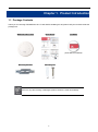
1.1 Package Contents
Thank you for choosing IFS WMC303-1W-1T-1200. Before installing the AP, please verify the contents inside the
package box.
WMC303-1W-1T-1200
Quick Guide
CD-ROM
(User Manual included)
Mounting Bracket
Mounting Kit
If there is any item missing or damaged, please contact the seller immediately.
-1-
1.2 Product Description
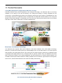
Ceiling Mount Designed for Highly-efficient Wireless Coverage
Featuring attractive flying saucer appearance and ceiling-mount design, the WMC303-1200 can be firmly
installed on the ceiling or the wall conveniently. The ceiling-mount design is smartly integrated into the
environment. Its streamlined body without the protruding antennas also gives effects of embellishment in the
surroundings. Moreover, the WMC303-1200 is compliant with the IEEE 802.3at PoE standard, so it is easy and
flexible in client-side installation. It is definitely nice to have this eye-catching access point mount on the ceilings
and walls of villas, hotels, exhibit halls, and other establishments.
Brand-new 11ac Wireless Technology
The WMC303-1200 supports IEEE 802.11a/b/g/n/ac dual band standards with 2T2R MIMO technology;
therefore, it provides the wireless speed up to 300+867Mbps, which is 16X faster than the 11a access point at
5GHz frequency and 5.5X faster than the 11g access point at 2.4GHz frequency. Moreover, the WMC303-1200
is equipped with Gigabit Ethernet Port. Compared with the general wireless APs, the WMC303-1200 offers
faster transmission speed for the network applications and less interference to enhance data throughput. The
incredible wireless speed makes it ideal for handling multiple HD movie streams, high-resolution on-line games,
stereo music, VoIPs and data streams at the same time stably and smoothly.
11ac Innovations Bring Excellent Data Link Speed
-2-
The WMC303-1200 is built-in with high power amplifier and 4 highly-sensitive antennas which provide stronger
signal and excellent coverage even in the wide-ranging or bad environment. With adjustable transmit power
option, the administrator can flexibly reduce or increase the output power for various environments, thus
reducing interference to achieve maximum performance. To provide extremely high-speed user experience, the
WMC303-1200 adopts IEEE 802.11ac technology to extend the 802.11n 40MHz channel binding to 80MHz and
the implementation of 256-QAM modulation where higher transmitting/receiving rates go up to 867Mbps in
5GHz less interference frequency band. In addition, the WMC303-1200 is equipped with gigabit LAN port to
eliminate the restriction of 100Mbps Fast Ethernet wired connection to let users fully enjoy the high speed
provided by wireless. The IEEE 802.11ac also optimizes MU-MIMO (Multi-User MIMO) mechanism to serve
multiple devices simultaneously.
Full Support of Wireless Security Encryption and Wireless Value-added Features
In aspect of security, besides 64/128-bit WEP encryption, the WMC303-1200 is integrated with WPA / WPA2,
WPA-PSK / WPA2-PSK and 802.1x Radius authority to secure and protect your wireless LAN. It provides the
wireless MAC filtering and SSID broadcast control to consolidate the wireless network security and prevent
unauthorized wireless connection. Being an access point, the WMC303-1200 supports the VLAN function to
allow multiple SSIDs (10 sets of SSIDs) to access Internal VLAN topology. Moreover, its Wi-Fi Multimedia (WMM)
mechanism provides enhanced QoS over wireless connection for better performance in multimedia transmission
like on-line gaming and video streaming, which are classified as a top priority.
-3-
Multiple Operation Modes for Various Applications
The WMC303-1200 supports AP, Client, WDS Bridge, Repeater and Universal Repeater modes, through which
it provides more flexibility for users when wireless network is established. Compared with general wireless
access point, the WMC303-1W-1T-1200 offers more powerful and flexible capability for wireless clients.
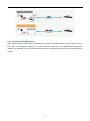
Flexible Deployment with PoE Feature
Compliant with the IEEE 802.3at Power over Ethernet standard, the WMC303-1200 can be powered and
networked by a single UTP cable. It thus reduces the needs of extra cables and dedicated electrical outlets on
the wall, ceiling or any other place where it is difficult to reach. The wireless network deployment becomes more
flexible and worry-free from the power outlet locations.
-4-
Easy Installation and Management
With user-friendly Web UI and step-by-step Quick Setup Wizard, the WMC303-1200 is easy to install, even for
users who never experience setting up a wireless network. Furthermore, with SNMP-based management
interface, the WMC303-1200 is convenient to be managed and configured remotely in a small business wireless
network.
-5-
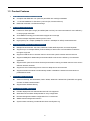
1.3 Product Features
Standard Compliant Hardware Interface
Complies with IEEE 802.11ac (draft 2.0) and IEEE 802.11a/b/g/n standards
1 x 10/100/1000Base-TX Port with 1-port PoE (PD, Powered Device)
IEEE 802.3at Power over Ethernet design
RF Interface Characteristics
Features 2.4GHz (802.11b/g/n) and 5GHz (802.11a/n/ac) concurrent dual band for more efficiency
of carrying high load traffic
2T2R MIMO technology for enhanced throughput and coverage
Provides multiple adjustable transmit power control
High speed up to 1.2Gbps (300Mbps for 2.4GHz + 867Mbps for 5GHz) wireless data rate
Comprehensive Wireless Advanced Features
Multiple Wireless Modes: AP, Client, WDS PtP/ PtMP, WDS Repeater, Universal Repeater
Supports up to 10 multiple-SSIDs (2.4GHz+5GHz) to allow users to access different networks
through a single AP
Supports VLAN function to limit the clients to access the specific internal network resource
Supports WMM (Wi-Fi Multimedia) and wireless QoS to enhance the efficiency of multimedia
application
Supports IAPP (Inter Access Point Protocol) and wireless roaming to enable clients to roam across
different wireless networks
Supports 5-level Transmitting Power Control to adapt various environments
Supports wireless schedule to automatically enable or disable the wireless function based on
predefined schedule
Secure Network Connection
Advanced security: 64/128-bit WEP, WPA / WPA2, WPA-PSK / WPA2-PSK (TKIP/AES encryption)
and 802.1x Radius Authentication
Supports MAC address filtering
Easy Installation & Management
Flexible deployment with standard 802.3at PoE/ PD supported
Web-based UI and Quick Setup Wizard for easy configuration
Remote Management allows configuration from a remote site
SNMP-based management interface
System status monitoring includes DHCP Client and System Log
-6-
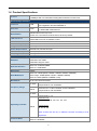
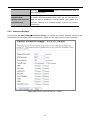
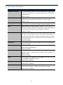
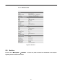
1.4 Product Specifications
Product
WMC303-1W-1T-1200
1200Mbps 802.11ac Dual Band Ceiling Mount Wireless Access Point
Hardware Specifications
Interfaces
LAN
1 x 10/100/1000Base-T RJ45 port
Auto-negotiation and Auto MDI/MDI-X
Antennas
Gain:
2 x 2.4GHz 2.5dBi PCBA antenna
2 x 5GHz 4dBi PCBA antenna
Reset Button
Reset button on the top cover
Press over 7 seconds to reset the device to factory default
LED Indicators
PWR
Allow LED to turn off via software control
Material
Plastic
Dimensions (Φ x H)
194 x 49 mm
Weight
300 ±5g
Power Requirements
802.3at PoE, 48-56V DC input
Power Consumption
20W (max.)
Mounting
Ceiling Mount
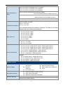
Wireless Interface Specifications
Standard
Antenna Structure
Modulation
IEEE 802.11ac (Draft 2.0) 5GHz
IEEE 802.11a/n 5GHz
IEEE 802.11b/g/n 2.4GHz
802.11ac: 2T2R MU-MIMO
802.11n: 2T2R MIMO
DSSS
802.11ac: OFDM (BPSK / QPSK / 16QAM / 64QAM / 256QAM)
Data Modulation
802.11a/g/n: OFDM (BPSK / QPSK / 16QAM / 64QAM)
802.11b: DSSS (DBPSK / DQPSK / CCK)
Band Mode
2.4G / 5G concurrent mode
2.4GHz
America/ FCC: 2.412~2.462GHz
Europe/ ETSI: 2.412~2.484GHz
5GHz
America/ FCC: 5.180~5.240GHz, 5.725~5.850GHz
Europe/ ETSI: 5.180~5.240GHz
2.4GHz
America/ FCC: 1~11
Europe/ ETSI: 1~13
Frequency Range
America/ FCC:
36, 40, 44, 48, 149, 153, 157, 161, 165
Operating Channels
5GHz
Europe/ ETSI:
36, 40, 44, 48
5GHz channel list will vary in different countries according to their
regulations.
Channel Width
802.11ac: 20/40/80MHz
802.11n: 20/40MHz
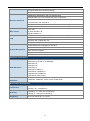
-7-
802.11ac (VHT20, Nss2-MCS8): Up to 173.3Mbps
802.11ac (VHT40, Nss2-MCS9): Up to 400Mbps
802.11ac (VHT80, Nss2-MCS9): Up to 867Mbps
Data Transmission
Rates
802.11n (HT40): 270/243/216/162/108/81/54/27Mbps
135/121.5/108/81/54/40.5/27/13.5Mbps (dynamic)
802.11n (HT20): 130/117/104/78/52/39/26/13Mbps
65/58.5/52/39/26/19.5/13/6.5Mbps (dynamic)
802.11g: 54/48/36/24/18/12/9/6Mbps (dynamic)
802.11b: 11/5.5/2/1Mbps (dynamic)
Transmission Distance
802.11ac (draft): up to 30m
802.11n: up to 70m
802.11g: up to 30m
The estimated transmission distance is based on the theory. The actual
distance will vary in different environments.
Max. RF Power
5GHz:
802.11ac (VHT20): 22dBm
802.11ac (VHT40): 22dBm
802.11ac (VHT80): 22dBm
802.11n (HT20): 22dBm
802.11n (HT40): 22dBm
802.11a: 22dBm
2.4GHz:
802.11n: 17 ±2.5dBm
802.11b/g: 20 ±2.5dBm
Receive Sensitivity
5GHz:
802.11ac (VHT20): -91dBm @ Nss1-MCS0, -64dBm @ Nss2-MCS8
802.11ac (VHT40): -89dBm @ Nss1-MCS0, -59dBm @ Nss2-MCS9
802.11ac (VHT80): -86dBm @ Nss1-MCS0, -56dBm @ Nss2-MCS9
802.11n (HT20): -92dBm @ MCS0, -71dBm @ MCS7
802.11n (HT40): -89dBm @ MCS0, -66dBm @ MCS15
802.11a: -93 @ 6Mbps, -75dBm @ 54Mbps
2.4GHz:
802.11n 20MHz (MCS7): -69dBm @10% PER
802.11n 40MHz (MCS15): -66dBm @10% PER
802.11g (54Mbps): -74dBm @10% PER
802.11b (11Mbps): -88dBm @10% PER
Software Features
Wireless Mode
Encryption Security
Wireless Security
Universal Repeater
(AP+Client)
Repeater
(WDS+AP)
AP (Access Point)
WEP (64/128-bit) encryption security
WPA / WPA2 (TKIP/AES)
WPA-PSK / WPA2-PSK (TKIP/AES)
WDS PTP (Point to Point)
WDS PTMP (Point to Multipoint)
Client
Provides wireless LAN ACL (Access Control List) filtering
Wireless MAC address filtering
-8-
Supports WPS (Wi-Fi Protected Setup)
Enable/ Disable SSID Broadcast
WMM (Wi-Fi Multimedia): 802.11e Wireless QoS
Multiple SSID: up to 5 at 2.4GHz and 5GHz, respectively
Wireless Advanced
Wireless Isolation: Enables to isolate each connected wireless client from
communicating with each other
IAPP (Inter Access Point Protocol): 802.11f Wireless Roaming
Provides Wireless Statistics
Max. Clients
Wire: 253
2.4GHz Wireless: 32
5GHz Wireless: 32
Built-in DHCP server supporting static IP address distributing
LAN
Supports UPnP
Supports 802.1d Spanning Tree
Supports 802.1Q VLAN
Web-based (HTTP) management interface
SNTP time synchronize
System Management
Easy firmware upgrade
Supports Scheduling Reboot
Standards Conformance
IEEE Standards
IEEE 802.11ac (Draft 2.0, 2T2R, up to 867Mbps)
IEEE 802.11n (2T2R, up to 300Mbps)
IEEE 802.11g
IEEE 802.11b
IEEE 802.11i
IEEE 802.3 10Base-T
IEEE 802.3u 100Base-TX
IEEE 802.3ab 1000Base-T
IEEE 802.3x Flow Control
Other Protocols and
Standards
CSMA/CA, CSMA/CD, TCP/IP, DHCP, ICMP, SNTP
Environment & Certification
Operating: 0 ~ 50 degrees C
Temperature
Storage: -40 ~ 70 degrees C
Operating: 10 ~ 90% (non-condensing)
Humidity
Regulatory
Storage: 5 ~ 90% (non-condensing)
FCC Part 15B & 15C, IC, RoHS
-9-
Chapter 2. Hardware Installation
Please follow the instructions below to connect WMC303-1W-1T-1200 to the existing network devices and your computers.
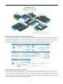
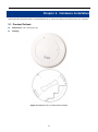
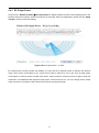
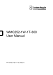
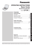
2.1 Product Outlook
Dimensions: 194 x 49 mm (Φ x H)
Drawing :
Figure 2-1 WMC303-1W-1T-1200 Product Drawing
-10-
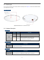
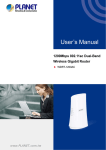
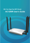
2.1.1 Panel Layout
The front and rear panel provide a simple interface monitoring the AP. Figure 2-2 shows the hardware interface
of the WMC303-1W-1T-1200.
Hardware Interface
Figure 2-2 WMC303-1W-1T-1200 Panel Layout
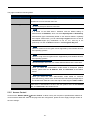
2.1.2 Hardware Description
LED definition
LED
COLOR
STATUS
Green
On
Device power on
Green
Off
Device power off (control by S/W)
Orange
On
System initializing, turned it off when system completed
PWR
FUNCTION
Detect and identify the LED (control by S/W)
Orange
Blinking
1) Position LED on: LED blinks continuously.
2) Position LED off: the LED is off.
Button definition
Object
Reset
Description
To restore to the factory default setting, press and hold the Reset Button over 7
seconds, and then release it.
Port definition
Object
PoE Port
(802.3at PoE)
Description
10/100/1000Mbps RJ-45 port , Auto MDI/ MDI-X
Connect PoE port to the IEEE 802.3at PSE to power on the device.
-11-
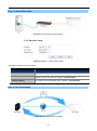
Chapter 3. Connecting to the AP
3.1 System Requirements
Broadband Internet Access Service (Cable/xDSL/Ethernet connection)
One IEEE 802.3at PoE switch (supply power to the WMC303-1200)
PCs with a working Ethernet Adapter and an Ethernet cable with RJ-45 connectors
PCs running Windows 98/ME, NT4.0, 2000/XP, Windows Vista / Win 7, MAC OS 9 or later, Linux,
UNIX or other platforms compatible with TCP/IP protocols
1. The AP in the following instructions refers to IFS WMC303-1200.
2. It is recommended to use Internet Explorer 7.0 or above to access the AP.
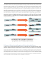
3.2 Installing the AP
Before installing the AP, make sure your PoE switch is connected to the Internet through the broadband service
successfully at this moment. If there is any problem, please contact your local ISP. After that, please install the
AP according to the following steps. Don't forget to pull out the power plug and keep your hands dry.
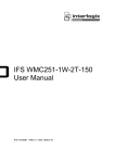
Step 1. Drill the outlet hole indicated on the mounting label and stick the given mounting label to the installation
location to let the Ethernet cable penetrate the outlet hole. Then, drill the mounting holes as indicated
on the label.
Figure 3-1 WMC303-1200 Installation Diagram 1
Step 2. Take the mounting bracket, put it on the target place by aligning the holes and fix it with the supplied
-12-
screws. ※ IEEE 802.3at PoE switch is required.
Figure 3-2 WMC303-1200 Installation Diagram 2
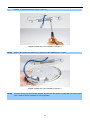
Step 3. Plug the RJ-45 Ethernet cable into the PoE port of the WMC303-1W-1T-1200.
Figure 3-3 WMC303-1200 Installation Diagram 3
Step 4. Load the device into the mounting bracket, and be sure the device is mated with two fixed screws.
Then, rotate the device clockwise to lock it in position.
-13-
Figure 3-4 WMC303-1200 Installation Diagram 4
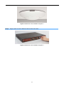
Step 5. Plug the other end of the Ethernet cable into the PoE switch.
Figure 3-5 WMC303-1200 Installation Diagram 4
-14-
Chapter 4. Quick Installation Guide
This chapter will show you how to configure the basic functions of your AP within minutes.
A computer with wired Ethernet connection to the Wireless AP is required for the first-time
configuration.
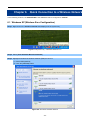
4.1 Manual Network Setup - TCP/IP Configuration
The default IP address of the WMC303-1200 is 192.168.0.253. And the default Subnet Mask is 255.255.255.0.
These values can be changed as you want. In this guide, we use all the default values for description.
Connect the WMC303-1200 with your PC by an Ethernet cable plugging in LAN port on one side and in LAN port
of PC on the other side. Please power on the WMC303-1200 by PoE switch through the PoE port.
In the following sections, we’ll introduce how to install and configure the TCP/IP correctly in Windows 7. And the
procedures in other operating systems are similar. First, make sure your Ethernet Adapter is working, and refer
to the Ethernet adapter manual if needed.
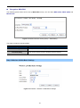
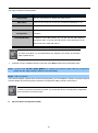
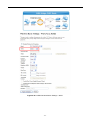
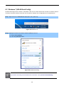
4.1.1 Configuring the IP Address Manually
Summary:
Set up the TCP/IP Protocol for your PC.
Configure the network parameters. The IP address is 192.168.1.xxx (if the default IP address of the
WMC303-1200 is 192.168.0.253, and the DSL router is 192.168.0.253, the "xxx" can be configured to
any number from 1 to 252), Subnet Mask is 255.255.255.0.
1
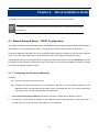
Select Use the following IP address radio button, and then configure the IP address of the PC.
2
For example, as the default IP address of the WMC303-1200 is 192.168.0.253 and the DSL router is
192.168.0.253, you may choose from 192.168.0.1 to 192.168.0.252.
-15-
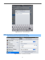
Figure 4-1 TCP/IP Setting
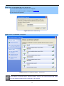
Now click OK to save your settings.
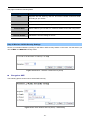
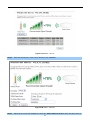
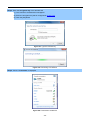
Now, you can run the Ping command in the command prompt to verify the network connection between your
PC and the AP. The following example is in Windows 7 OS. Please follow the steps below:
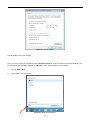
1.
Click on Start > Run.
2.
Type “cmd” in the Search box.
Figure 4-2 Windows Start Menu
-16-
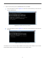
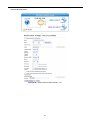
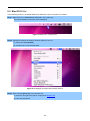
3.
Open a command prompt, type ping 192.168.0.253 and then press Enter.
If the result displayed is similar to Figure 4-3, it means the connection between your PC and the AP
has been established well.
Figure 4-3 Successful result of Ping command
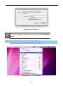
If the result displayed is similar to Figure 4-4, it means the connection between your PC and the AP
has failed.
Figure 4-4 Failed Result of Ping Command
If the address is 0.0.0.0, check your adapter installation, security settings, and the settings on your AP. Some
firewall software programs may block a DHCP request on newly installed adapters.
-17-
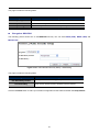
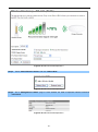
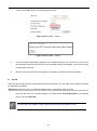
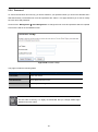
4.2 Starting Setup in the Web UI
It is easy to configure and manage the AP with the web browser.
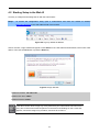
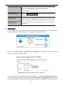
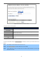
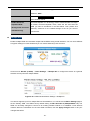
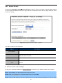
Step 1.
To access the configuration utility, open a web-browser and enter the default IP address
http://192.168.0.253 in the web address field of the browser.
Figure 4-5 Login by default IP address
After a moment, a login window will appear. Enter admin for the User Name and Password, both in lower case
letters. Then click the OK button or press the Enter key.
Figure 4-6 Login Window
Default IP Address: 192.168.0.100
Default User name: admin
Default Password: admin
If the above screen does not pop up, it may mean that your web-browser has been set to a
proxy. Go to Tools menu>Internet Options>Connections>LAN Settings on the screen that
appears, cancel the Using Proxy checkbox, and click OK to finish it.
-18-
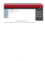
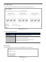
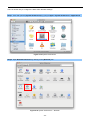
Chapter 5. Configuring the AP
This chapter delivers a detailed presentation of AP’s functionalities and features under 6 main menus below,
allowing you to manage the AP with ease.
Figure 5-1 Main Menu
During operation, if you are not clear about a certain feature, you can refer to the “Help” section in the right side
of the screen to read all related helpful info.
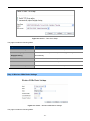
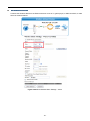
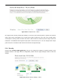
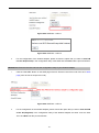
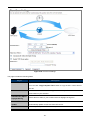
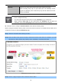
5.1 Setup Wizard
The Setup Wizard will guide the user to configure the WMC303-1200 easily and quickly. Select the Setup Wizard
on the left side of the screen and by clicking on Next on the Setup Wizard screen shown below, you will then
name your WMC303-1200 and set up its security.
Figure 5-2 Setup Wizard
-19-
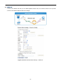
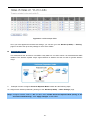
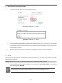
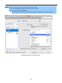
Step 1: LAN Interface Setup
Figure 5-3 LAN Interface SetupTopology
Figure 5-4 Wizard – LAN Interface Setup
The page includes the following fields:
Object
Description
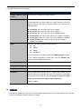
IP Address
Displays the current IP address of the AP. (Default = 192.168.0.100)
Subnet Mask
Displays LAN mask of the AP. (Default = 255.255.255.0)
Default Gateway
IP address of the associated router. (Default = 192.168.0.253)
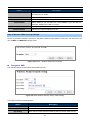
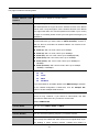
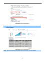
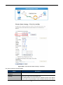
Step 2: Time Zone Setting
Figure 5-5 Time Zone Setup Topology
-20-
Figure 5-6 Wizard – Time Zone Setup
The page includes the following fields:
Object
Description
Enable NTP client update
Check this box to connect NTP Server and synchronize internet time.
Automatically adjust
Check this box and system will adjust the daylight saving
Daylight Saving
automatically.
Time Zone Select
Select the Time Zone from the drop-down menu.
NTP Server
Select the NTP Server from the drop-down menu.
Enable NTP client update
Check this box to connect NTP Server and synchronize internet time.
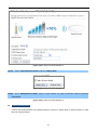
Step 3: Wireless 5GHz Basic Settings
Figure 5-7 Wizard – Wireless 5GHz Basic Settings
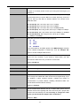
The page includes the following fields:
-21-
Object
Description
Band
Supports 802.11a, 802.11n, 802.11ac and mixed. Please choose its band
according to your clients.
Mode
Supports AP, Client, WDS and AP+WDS mode.
SSID
Service Set Identifier identifies your wireless network.
Channel Width
Select 80MHz if you use 802.11ac; select 40MHz if you use 802.11n;
otherwise, 20MHz for the 802.11a mode.
Control Sideband
It is only valid when you choose channel width 40MHz.
Channel Number
Indicates the channel setting for the AP.
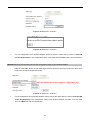
Step 4: Wireless 5GHz Security Settings
Secure your wireless network by turning on the WPA or WEP security feature on the router. For this section you
can set WEP and WPA-PSK security mode.
Figure 5-8 Wizard – Wireless 5GHz Security Setup
Encryption: WEP
The following picture shows how to set the WEP security.
Figure 5-9 5GHz Wireless Security Setup – WEP Setting
The page includes the following fields:
Object
Description
Key length
WEP supports 64-bit or 128-bit security key.
Key Format
User can enter key in ASCII or Hex format.
Key Setting
Enter the key whose format is limited by the Key format, ASCII or Hex.
-22-
Encryption: WPA-PSK
The following picture shows how to set up WPA-PSK security. You can select WPA (TKIP), WPA2 (AES) and
Mixed mode.
Figure 5-10 5GHz Wireless Security Setup – WPA Setting
The page includes the following fields:
Object
Description
Pre-Shared Key Format
Pre-Shared Key
Specify the format of the key, pass phrase or hex.
Enter the key whose format is limited by the key format.
Step 5: Wireless 2.4GHz Basic Settings
Figure 5-11 Wizard – Wireless 2.4GHz Basic Settings
-23-
The page includes the following fields:
Object
Description
Band
Supports 802.11b, 802.11g, 802.11n and mixed. Please choose its band
according to your clients.
Mode
Supports AP, Client, WDS and AP+WDS mode.
SSID
Service Set Identifier, it identifies your wireless network.
Select 40MHz if you use 802.11n, otherwise 20MHz for the 802.11b/g mode.
Channel Width
Control Sideband
It is only valid when you choose channel width 40MHz.
Channel Number
Indicates the channel setting for the AP.
Step 6: Wireless 2.4GHz Security Settings
Secure your wireless network by turning on the WPA or WEP security feature on the router. For this section you
can set WEP and WPA-PSK security mode.
Figure 5-12 Wizard – Wireless 2.4GHz Security Setup
Encryption: WEP
The following picture shows how to set the WEP security.
Figure 5-13 2.4GHz Wireless Security Setup – WEP Setting
-24-
The page includes the following fields:
Object
Description
Key Length
WEP supports 64-bit or 128-bit security key.
Key Format
User can enter key in ASCII or Hex format.
Key Setting
Enter the key whose format is limited by the Key format, ASCII or Hex.
Encryption: WPA-PSK
The following picture shows how to set WPA-PSK security. You can select WPA (TKIP), WPA2 (AES) and
Mixed mode.
Figure 5-14 2.4GHz Wireless Security Setup – WPA Setting
The page includes the following fields:
Object
Pre-Shared Key Format
Pre-Shared Key
Description
Specify the format of the key, pass phrase or hex.
Enter the key whose format is limited by the key format.
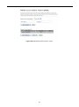
Click the Finished button to make your wireless configuration to take effect and finish the Setup Wizard.
-25-
Figure 5-15 Setup Wizard - Finished
After rebooting, please check whether you can access the Internet or not on the “Status” page.
-26-
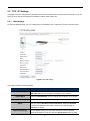
5.2 TCP / IP Settings
This page is used to configure the parameters for local area network which connects to the LAN port of your AP.
Here you may change the setting for IP address, subnet mask, DHCP, etc.
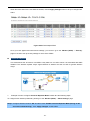
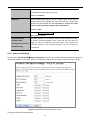
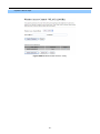
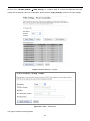
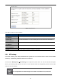
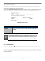
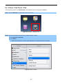
5.2.1 LAN Settings
On the LAN Settings page, you can configure the IP parameters of the LAN on the screen as shown below.
Figure 5-16 LAN Setting
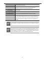
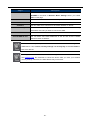
The page includes the following fields:
Object
IP Address
Description
The default LAN IP address of the WMC303-1W-1T-1200 is
192.168.0.100. You can change it according to your request.
Subnet Mask
Default is 255.255.255.0. You can change it according to your request.
Default Gateway
Default is 192.168.0.253. You can change it according to your request.
DHCP
You can select a Disabled, Client, and Server. Default is Disabled,
meaning the WMC303-1200 must connect to a router to assign IP
addresses to clients.
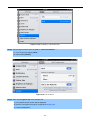
DHCP Client Range
For the Server mode, you must enter the DHCP client IP address
range in the field. And you can click the “Show Client” button to show
-27-
the Active DHCP Client Table.
Static DHCP
Click the “Set Static DHCP” button and you can reserve some IP
addresses for those network devices with the specified MAC
addresses anytime when they request IP addresses.
Domain Name
802.1d Spanning Tree
Clone MAC Address
UPnP Enable
Default is IFS.
You can enable or disable the Spanning Tree function.
You can input an MAC address here for using clone function.
You can enable or disable the UPnP function.
The UPnP feature allows the devices, such as Internet computers, to
access the local host resources or devices as needed. UPnP devices
can be automatically discovered by the UPnP service application on
the LAN.
If you change the IP address of LAN, you must use the new IP address to login the
AP.
When the IP address of the WMC303-1200 is changed, the clients on the network
often need to wait for a while or even reboot before they can access the new IP
address. For an immediate access to the AP, please flush the netbios cache on the
client computer by running the “nbtstat –r” command before using the device
name of the WMC303-1200 to access its Web Management page.
-28-
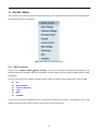
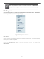
5.3 WLAN1 (5GHz)
The wireless menu of WLAN1 (5GHz) contains submenus of the settings about wireless network. Please refer to
the following sections for the details.
Figure 5-17 5GHz Wireless Main Menu
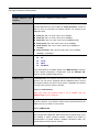
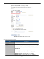
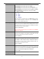
5.3.1 Basic Settings
Choose menu “WLAN1 (5GHz) Basic Settings” and you can configure the 5GHz basic settings for the
wireless network on this page. After the configuration is done, please click the “Apply Changes” button to save
the settings.
First of all, the wireless AP supports multiple wireless modes for different network applications, which include:
AP
Multiple SSIDs
Universal Repeater
Client
WDS
AP+WDS
It is so easy to combine the WMC303-1W-1T-1200 with the existing wired network. The WMC303-1W-1T-1200
definitely provides a total network solution for the home and the SOHO users.
-29-
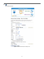
AP
Standard Access Point
Figure 5-18 5GHz Wireless Basic Settings of AP
-30-
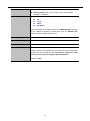
The page includes the following fields:
Object
Disable Wireless LAN
Description
Check the box to disable the wireless function.
Interface
Band
Select the desired mode. Default is “5GHz (A+N+AC)”. It is strongly
recommended that you set the Band to “5GHz (A+N+AC)”, and all of
802.11a, 802.11n, and 802.11ac wireless stations can connect to the
WMC303-1W-1T-1200.
5 GHz (A): 802.11a mode, rate is up to 54Mbps
5 GHz (N): 802.11n mode, rate is up to 300Mbps
5 GHz (AC): 802.11n mode, rate is up to 867Mbps(2T2R)
5 GHz (A+N): 802.11a/n mode, rate is up to 300Mbps
5 GHz (N+AC): 802.11n/ac mode, rate is up to 300Mbps or
867Mbps
5 GHz (A+N+AC): 802.11a/n/ac mode, rate is up to 54Mbps,
300Mbps, or 867Mbps
Mode
There are four kinds of wireless mode selections:
AP
Client
WDS
AP+WDS
If you select WDS or AP+WDS, please click “WDS Settings” submenu
for the related configuration. Furthermore, click the “Multiple AP”
button to enable multiple SSID functions.
SSID
The ID of the wireless network. User can access the wireless network
through it only. However, if you switch to Client Mode, this field
becomes the SSID of the AP you want to connect with.
Default: IFS AP 5G
Channel Width
You can select 20MHz, 40MHz or 80MHz.
Channel Number
You can select the operating frequency of wireless network.
Default: 40
Broadcast SSID
If you enable “Broadcast SSID”, every wireless station located within
the coverage of the AP can discover its signal easily. If you are building
a public wireless network, enabling this feature is recommended. In
private network, disabling “Broadcast SSID” can provide better
wireless network security.
Default is “Enabled”.
Data Rate
Set the wireless data transfer rate to a certain value. Since most of
wireless devices will negotiate with each other and pick a proper data
-31-
transfer rate automatically, it’s not necessary to change this value
unless you know what will happen after modification.
Default is “Auto”.
Associated Clients
Click the “Show Active Clients” button to show the status table of
active wireless clients.
Enable Universal
Universal Repeater is a technology used to extend wireless coverage.
Repeater Mode
To enable Universal Repeater Mode, check the box and enter the
(Acting as AP and client
simultaneously)
SSID you want to broadcast in the field below. Then please click
“Security” submenu for the related settings of the AP you want to
connect with.
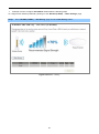
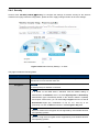
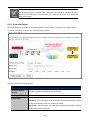
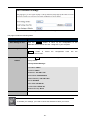
Multiple-SSID
Enable multiple-SSID can broadcast multiple WLAN SSID's using virtual interfaces. You can have different
encryption settings for each WLAN and you can restrict what they have access to.
Choose menu “WLAN1 (5GHz) → Basic Settings → Multiple AP” to configure the device as a general
wireless access point with multiple SSIDs.
Figure 5-19 5GHz Wireless Basic Settings – Multiple AP
The device supports up to four multiple Service Set Identifiers. You can back to the Basic Settings page to
set the Primary SSID. The SSID’s factory default setting is IFS 5G VAP1~4 (Multiple-SSID 1~4). The SSID
can be easily changed to connect to an existing wireless network or to establish a new wireless network.
-32-
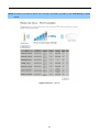
When the information for the new SSID is finished, click the Apply Changes button to let your changes take
effect.
Figure 5-20 5GHz Multiple-SSID
Once you have applied and saved those settings, you can then go to the “WLAN1 (5GHz) → Security”
page on the AP to set up security settings for each of the SSIDs.
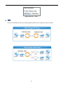
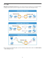
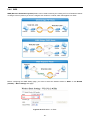
Universal Repeater
This mode allows the AP with its own BSS to relay data to a root AP to which it is associated with WDS
disabled. The wireless repeater relays signal between its stations and the root AP for greater wireless
range.
1.
Example of how to configure Universal Repeater Mode. Please take the following steps:
To configure each wireless parameter, please go to the “WLAN1 (5GHz) → Basic Settings” page.
Step 1. Configure wireless mode to “AP” and then check “Enable Universal Repeater Mode (Acting as AP
and client simultaneously)”. Click “Apply Changes” to take effect.
-33-
Figure 5-21 5GHz Universal Repeater-1
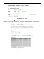
Step 2. Go to 5GHz Site Survey page to find the root AP. Select the root AP that you want to repeat the signal
and then click “Next”.
Figure 5-22 5GHz Universal Repeater-2
Step 3. Select the correct encryption method and enter the security key. Then, click “Connect”.
-34-
Figure 5-23 5GHz Universal Repeater-3
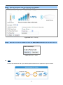
Step 4. Check “Add to Wireless Profile” and click “Reboot Now”.
Figure 5-24 5GHz Universal Repeater-4
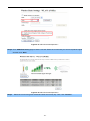
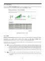
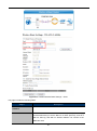
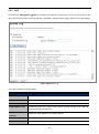
Step 5. Go to “Management-> Status” page to check whether the state of Repeater interface should be
“Connected”.
Figure 5-25 5GHz Universal Repeater-5
-35-
Client (Infrastructure)
Combine the Wireless Router to the Ethernet devices such as TV, game player, or HDD and DVD, to make
them be wireless stations.
Figure 5-26 5GHz Wireless Basic Settings – Client
-36-
The page includes the following fields:
Object
Disable Wireless LAN
Description
Check the box to disable the wireless function.
Interface
Band
Select the desired mode. Default is “5GHz (A+N+AC)”. It is strongly
recommended that you set the Band to “5GHz (A+N+AC)”, and all of
802.11a, 802.11n, and 802.11ac wireless stations can connect to the
WMC303-1200.
5 GHz (A): 802.11a mode, rate is up to 54Mbps
5 GHz (N): 802.11n mode, rate is up to 300Mbps
5 GHz (AC): 802.11n mode, rate is up to 867Mbps(2T2R)
5 GHz (A+N): 802.11a/n mode, rate is up to 300Mbps
5 GHz (N+AC): 802.11n/ac mode, rate is up to 300Mbps or
867Mbps
5 GHz (A+N+AC): 802.11a/n/ac mode, rate is up to 54Mbps,
300Mbps, or 867Mbps
Mode
There are four kinds of wireless mode selections:
AP
Client
WDS
AP+WDS
If you select WDS or AP+WDS, please click “WDS Settings” submenu
for the related configuration. Furthermore, click the “Multiple AP”
button to enable multiple SSID function.
Network Type
In Infrastructure, the wireless LAN serves as a wireless station. And
the user can use the PC equipped with the WMC303-1200 to access
the wireless network via other access points. In Ad hoc, the wireless
LAN will use the Ad-hoc mode to operate.
Default is “Infrastructure”.
Note: Only while the wireless mode is set to “Client”, then the
Network Type can be configured.
SSID
The ID of the wireless network. User can access the wireless network
via its ID. However, if you switch to Client mode, this field becomes the
SSID of the AP you want to connect with.
Default: WMC303 5G
Broadcast SSID
If you enable “Broadcast SSID”, every wireless station located within
the coverage of the WMC303-1200 can discover its signal easily. If you
are building a public wireless network, enabling this feature is
recommended. In private network, disabling “Broadcast SSID” can
provide better wireless network security.
-37-
Default is “Enabled”.
Data Rate
Set the wireless data transfer rate to a certain value. Since most of
wireless devices will negotiate with each other and pick a proper data
transfer rate automatically, it’s not necessary to change this value
unless you know what will happen after modification.
Default is “Auto”.
Enable Mac Clone
Enable Mac Clone.
(Single Ethernet Client)
Example of how to configure Client Mode. Please take the following steps:
To configure each wireless parameter, please go to the “WLAN1 (5GHz) → Basic Settings” page.
Step 1. Go to “WLAN1 (5GHz) → Site Survey” page and click “Site Survey” button.
Figure 5-27 Client – Survey
Step 2. Choose the root AP from the list. If the root AP is not listed in the table, re-click “Site Survey” to update
the list.
-38-
Figure 5-28 Client – AP List
Step 3. Enter the Security Key of the root AP and then click “Connect”.
Figure 5-29 Client – Security
Step 4. Wait until the connection established. Check the “Add to Wireless Profile” option and then reboot it.
-39-
Figure 5-30 Client – Status
WDS
Connect this Wireless AP with up to 8 WDS-capable wireless APs to expand the scope of network.
-40-
Figure 5-31 5GHz Wireless Basic Settings – WDS
The page includes the following fields:
Object
Disable Wireless LAN
Description
Check the box to disable the wireless function.
Interface
Band
Select the desired mode. Default is “5GHz (A+N+AC)”. It is strongly
recommended that you set the Band to “5GHz (A+N+AC)”, and all of
802.11a, 802.11n, and 802.11ac wireless stations can connect to the
WMC303-1200.
5 GHz (A): 802.11a mode, rate is up to 54Mbps
5 GHz (N): 802.11n mode, rate is up to 300Mbps
5 GHz (AC): 802.11n mode, rate is up to 867Mbps(2T2R)
5 GHz (A+N): 802.11a/n mode, rate is up to 300Mbps
5 GHz (N+AC): 802.11n/ac mode, rate is up to 300Mbps or
-41-
867Mbps
5 GHz (A+N+AC): 802.11a/n/ac mode, rate is up to 54Mbps,
300Mbps, or 867Mbps
Mode
There are four kinds of wireless mode selections:
AP
Client
WDS
AP+WDS
If you select WDS or AP+WDS, please click “WDS Settings” submenu
for the related configuration. Furthermore, click the “Multiple AP”
button to enable multiple SSID function.
Channel Width
You can select 20MHz, 40MHz or 80MHz.
Control Sideband
You can select Upper or Lower.
Channel Number
You can select the operating frequency of wireless network.
Data Rate
Set the wireless data transfer rate to a certain value. Since most of
wireless devices will negotiate with each other and pick a proper data
transfer rate automatically, it’s not necessary to change this value
unless you know what will happen after modification.
Default is “Auto”.
-42-
AP+ WDS
Connect this wireless AP with up to 8 WDS-capable wireless APs, and connect another AP to provide
service for all wireless stations within its coverage.
Figure 5-32 5GHz Wireless Basic Settings – WDS+AP
-43-
The page includes the following fields:
Object
Disable Wireless LAN
Description
Check the box to disable the wireless function.
Interface
Country
Select your region from the pull-down list.
This field specifies the region where the wireless function of the Router
can be used. It may be illegal to use the wireless function of the Router
in a region other than one of those specified in this field. If your country
or region is not listed, please contact your local government agency for
assistance.
Band
Select the desired mode. Default is “5GHz (A+N+AC)”. It is strongly
recommended that you set the band to “5GHz (A+N+AC)”, and all of
802.11a, 802.11n, and 802.11ac wireless stations can connect to the
WMC303-1200.
5 GHz (A): 802.11a mode, rate is up to 54Mbps
5 GHz (N): 802.11n mode, rate is up to 300Mbps
5 GHz (AC): 802.11n mode, rate is up to 867Mbps(2T2R)
5 GHz (A+N): 802.11a/n mode, rate is up to 300Mbps
5 GHz (N+AC): 802.11n/ac mode, rate is up to 300Mbps or
867Mbps
5 GHz (A+N+AC): 802.11a/n/ac mode, rate is up to 54Mbps,
300Mbps, or 867Mbps
Mode
There are four kinds of wireless mode selections:
AP
Client
WDS
AP+WDS
If you select WDS or AP+WDS, please click “WDS Settings” submenu
for the related configuration. Furthermore, click the “Multiple AP”
button to enable multiple SSID functions.
SSID
The ID of the wireless network. User can access the wireless network
via its ID only. However, if you switch to Client Mode, this field
becomes the SSID of the AP you want to connect with.
Default: WMC303 5G
Channel Width
You can select 20MHz, 40MHz or 80MHz.
Control Sideband
You can select Upper or Lower.
Channel Number
You can select the operating frequency of wireless network.
Broadcast SSID
If you enable “Broadcast SSID”, every wireless station located within
the coverage of the WMC303-1200 can discover its signal easily. If you
are building a public wireless network, enabling this feature is
-44-
recommended. In private network, disabling “Broadcast SSID” can
provide better wireless network security.
Default is “Enabled”.
Set the wireless data transfer rate to a certain value. Since most of
Data Rate
wireless devices will negotiate with each other and pick a proper data
transfer rate automatically, it’s not necessary to change this value
unless you know what will happen after modification.
Default is “Auto”.
Associated Clients
Click the “Show Active Clients” button to show the status table of
active wireless clients.
Enable Universal
Universal Repeater is a technology used to extend wireless coverage.
Repeater Mode
To enable Universal Repeater mode, check the box and enter the
(Acting as AP and client
simultaneously)
SSID you want to broadcast in the field below. Then please click
“Security” submenu for the related settings of the AP you want to
connect with.
5.3.2 Advanced Settings
Choose menu “WLAN1 (5GHz) Advanced Settings” and you can configure the 5GHz advanced settings for
the wireless network on this page. After the configuration, please click the “Apply” button to save the settings.
Figure 5-33 Wireless Advanced Settings – 5GHz
The page includes the following fields:
-45-
Object
Fragment Threshold
Description
You can specify the maximum size of packet during the fragmentation
of data to be transmitted. If you set this value too low, it will result in
bad performance.
Default is “2346”.
RTS Threshold
When the packet size is smaller than the RTS threshold, the access
point will not use the RTS/CTS mechanism to send this packet.
Default is “2347”.
Beacon Interval
The interval of time that this access point broadcasts a beacon.
Beacon is used to synchronize the wireless network. Default is “100”.
IAPP
IAPP (Inter-Access Point Protocol) enabled is recommended as it
describes an optional extension to IEEE 802.11 that provides wireless
access-point communications among multivendor systems.
Default is “Enabled”.
Protection
It is recommended to enable the protection mechanism. This
mechanism can decrease the rate of data collision between 802.11b
and 802.11g wireless stations. When the protection mode is enabled,
the throughput of the AP will be a little lower due to the transmission of
heavy frame traffic.
Default is “Disabled”.
Aggregation
It is a function where the values of multiple rows are grouped together.
Default is “Enabled”
Short GI
It is used to set the time that the receiver waits for RF reflections to
settle out before sampling data.
Default is “Enabled”
WLAN Partition
This feature is also called “WLAN isolation” or “Block Relay”. If this is
enabled, wireless clients cannot exchange data through the
WMC303-1200.
Default is “Disabled”.
STBC
Activate Space Time Blocking Code (STBC) which does not need
channel statement information (CSI).
Default Setting: "Enabled"
LDPC
Low-density Parity-check Code is wireless data transmit algorithm.
Default Setting: "Enabled"
5.3.3 RF Output Power
Choose menu “WLAN1 (5GHz) RF Output Power” to adjust to different levels of transmitting power for the
wireless network according to various environments on this page. After the configuration, please click the “Apply
Changes” button to save the settings.
-46-
Figure 5-34 RF Output Power – 5GHz
RF Output Power Control provides the flexibility to control the Wi-Fi transmit power to optimize the wireless
range. Wi-Fi power consumption for an Access Point could be reduced to up to 75% from its peak power
consumption for serving small to medium size homes, while boosted to maximum power for large homes and
businesses. The WMC303-1200 supports output power control levels up to 5. You can change the RF output
power level here in accordance with various environments and signal strength.
5.3.4 Security
Choose menu “WLAN1 (5GHz) Security” and you can configure the settings of wireless security for the
wireless network on this page. After the configuration, please click the “Apply Changes” button to save the
settings.
Figure 5-35 Wireless Security Settings – 5GHz
-47-
The page includes the following fields:
Object
Description
Select SSID
Select the SSID you want to configure the wireless security function, which
includes the root one and the client one.
Encryption
Disable:
No security setup for wireless connection.
WEP:
It is based on the IEEE 802.11 standard. And the default setting of
authentication is Automatic, which can select Open System or Shared Key
authentication type automatically based on the wireless station's capability
and request. Furthermore, you can select Key Length and enter 10 and 26
Hexadecimal digits (any combination of 0-9, a-f, A-F, zero key is not
promoted) or 5 and 13 ASCII characters in the Encryption Key field.
WPA:
WPA is a medium level encryption and is supported by most wireless devices
and operating systems.
WPA2:
WPA2 is a high level encryption and is supported by most wireless devices
and operating systems.
WPA / WPA2 / WPA-Mixed:
WPA Mixed Mode allows the use of both WPA and WPA2 at the same time.
Authentication Mode
Enterprise (RADIUS)
When you select the authentication mode based on Enterprise (Radius
Server), please enter the IP Address, Port, and Password of the Radius
Server.
Personal (Pre-Shared Key)
When you select the other authentication mode based on Personal
(Pre-Shared Key), please enter at least 8 ASCII characters (Passphrase) or
64 Hexadecimal characters. All of the Cipher Suites support TKIP and AES.
802.1x Authentication
Enable 802.1x authentication function and then please enter the IP Address,
Port, and Password of the Radius Server.
5.3.5 Access Control
Choose menu “WLAN1 (5GHz) Access Control” to allow or deny the computer of specified MAC address to
connect with the WMC303-1200 on this page. After the configuration, please click the “Apply Changes” button to
save the settings.
-48-
Figure 5-36 Wireless Access Control – 5GHz
The page includes the following fields:
Object
Wireless Access
Description
You can choose to set the Allowed-List, Denied-List, or disable this function.
Control Mode
MAC Address
Enter the MAC address you want to allow or deny connection to the
WMC303-1200 in the field.
Comment
Current Access Control
List
You can make some comment on each MAC address on the list.
You can select some MAC addresses and click the “Delete Selected” button to
delete it.
To deny a PC at the MAC address of 9c:F6:1A:00:00:01 (for example) to connect to your wireless network, do as
follows:
Step 1.
Select “Deny” from MAC Address Filter drop-down menu.
Step 2.
Enter 9c:F6:1A:00:00:01 in the MAC address box and click “Add”.
Step 3.
Click the “OK” button to save your settings and you can add more MAC addresses, if you like, simply
repeat the above steps.
-49-
Figure 5-37 Wireless Access Control – Deny
-50-
5.3.6 WDS
WDS (Wireless Distribution System) feature can be used to extend your existing 2.4G or 5G wireless network
coverage. Here we present you how to configure such feature in 2.4GHz, which also applies to 5GHz.
Before configuring the WDS Setting page, you have to select the wireless mode to “WDS” on the WLAN1 (5GHz)
-> Basic Settings web page.
-51-
Figure 5-38 WDS Mode – 5GHz
Choose menu “WLAN1 (5GHz) WDS Settings” to configure WDS to connect the WMC303-1W-1T-1200 with
another AP on this page. After the configuration, please click the “Apply Changes” button to save the settings.
Figure 5-39 WDS Settings – 5GHz
-52-
Figure 5-40 WDS – Set Security
The page includes the following fields:
Object
Description
Enable WDS
Check the box to enable the WDS function. Please select WDS or
AP+WDS in the Mode of Wireless Basic Settings before you enable
WDS on this page.
MAC Address
You can enter the MAC address of the AP you want to connect with.
Data Rate
Default is “Auto”.
Comment
You can make some comment for each MAC address on the list.
Set Security
Click the “Set Security” button to configure the wireless security
parameters of the AP you want to connect via WDS.
Show Statics
Current WDS AP List
Click the “Show Statics” button to show the WDS AP.
You can select some MAC addresses of the AP and click the “Delete
Selected” button to delete it.
WDS feature can only be implemented between 2 wireless devices that both support the WDS
feature. Plus, channel, security settings and security key must be the same on both such
devices.
To encrypt your wireless network, click “Set Security”. For the detail of wireless security, see
section 5.3.3. Do remember to reboot the device after you save your wireless security settings;
otherwise, the WDS feature may not function.
-53-
5.3.7 Site Survey
Choose menu “WLAN1 (5GHz) Site Survey” to scan the available local AP. If any Access Point is found, you
could choose any one to connect with manually when the Client Mode is enabled.
Figure 5-41 Site Survey – 5GHz
5.3.8 WPS
WPS (Wi-Fi Protected Setup) is designed to ease setup of security Wi-Fi networks and subsequently network
management.
This
Wireless
Router
supports
WPS
features
for
AP
mode,
AP+WDS
mode,
Infrastructure-Client mode, and the wireless root interface of Universal Repeater mode.
Simply enter a PIN code or press the software PBC button or hardware WPS button (if any) and a secure
wireless connection is established.
PBC: If you find the WPS LED blinking for 2 minutes after you press the hardware WPS button on the
device, it means that PBC encryption method is successfully enabled. And an authentication will
be performed between your router and the WPS/PBC-enabled wireless client device during this
time; if it succeeds, the wireless client device connects to your device, and the WPS LED turns
off. Repeat steps mentioned above if you want to connect more wireless client devices to the
device.
PIN:To use this option, you must know the PIN code from the wireless client and enter it in
corresponding field on your device while using the same PIN code on client side for such
connection.
-54-
The page includes the following fields:
Object
Description
Disable WPS
You can check the box to disable the WPS function.
WPS Status
Here you can check if the connection via WPS is established or not.
Self-PIN Number
Push Button
Configuration
Client PIN Number
It is the PIN number of the WMC303-1W-1T-1200 here.
Click the “Start PBC” to activate WPS as well in the client device within
2 minutes.
In addition to the PBC method, you can also use the PIN method to
activate the WPS. Just enter the PIN number of the client device in the
field and click the “Start PIN” button.
The WPS encryption can be implemented only between your Router and another
WPS-capable device.
Example of how to establish wireless connection using WPS. Please take the following steps:
Step 1. Choose menu “WLAN1 (5GHz) WPS” to configure the setting for WPS. After the configuration,
please click the “Apply Changes” button to save the settings.
Step 2. Add a new device.
If the wireless adapter supports Wi-Fi Protected Setup (WPS), you can establish a wireless connection between
wireless adapter and AP using either Push Button Configuration (PBC) method or PIN method.
To build a successful connection by WPS, you should also do the corresponding configuration
of the new device for WPS function.
A.
By Push Button Configuration (PBC)
-55-
i.
Click the “Start PBC” Button on the WPS page of the AP.
Figure 5-42 WPS-PBC – 5GHz-1
Figure 5-43 WPS-PBC – 5GHz-2
ii.
Press and hold the WPS Button equipped on the adapter directly for 2 or 3 seconds. Or you can click
the WPS button with the same function in the configuration utility of the adapter. The process must be
finished within 2 minutes.
iii.
B.
Wait for a while until the next screen appears. Click OK to complete the WPS configuration.
By PIN
If the new device supports Wi-Fi Protected Setup and the PIN method, you can add it to the network by PIN with
the following two methods.
Method One: Enter the PIN of your Wireless adapter into the configuration utility of the AP
i.
Enter the PIN code of the wireless adapter in the field behind Client PIN Number in the following
figure. Then click Start PIN.
The PIN code of the adapter is always displayed on the WPS configuration screen.
-56-
Figure 5-44 WPS-PIN – 5GHz-1
Figure 5-45 WPS-PIN – 5GHz-2
ii.
For the configuration of the wireless adapter, please choose the option that you want to enter PIN
into the AP (Enrollee) in the configuration utility of the WPS and click Next until the process finishes.
Method Two: Enter the PIN of the AP into the configuration utility of your Wireless adapter
i.
Click the “Start PBC” Button on the WPS page of the AP. Get the Current PIN code of the AP in WPS
page (each AP has its unique PIN code).
Figure 5-46 WPS-PIN – 5GHz-3
ii.
For the configuration of the wireless adapter, please choose the option that you want to enter the PIN
of the AP (Registrar) in the configuration utility of the Wireless adapter and enter it into the field.
Then click Next until the process finishes.
-57-
5.3.9 Schedule
Wireless Schedules will enable or disable your wireless access at a set time based on your predefined schedule.
This feature is often used for restricting access to all users (such as children, employees and guests) during
specific times of the day for parental control or security reasons.
Choose menu “WLAN1 (5GHz) Schedule” to configure the schedule rule of enabling wireless function. After
the configuration, please click the “Apply Changes” button to save the settings.
Figure 5-47 Schedule - 5GHz
-58-
When setting the Wireless Schedule, it is important to ensure that your System Clock
settings have been configured. If not, your Wireless Schedule will not function correctly.
5.4 WLAN2 (2.4GHz)
The Wireless menu contains submenus of the settings about wireless network. Please refer to the following
sections for the details.
Figure 5-48 2.4GHz Wireless Main Menu
5.4.1 Basic Settings
Choose menu “WLAN2 (2.4GHz) Basic Settings” to configure the 2.4GHz basic settings for the wireless
network on this page. After the configuration is done, please click the “Apply Changes” button to save the
settings.
First of all, the wireless AP supports multiple wireless modes for different network applications, which include:
AP
Multiple SSIDs
Universal Repeater
Client
WDS
AP+WDS
It is so easy to combine the WMC303-1200 with the existing wired network. The WMC303-1200 definitely
provides a total network solution for the home and the SOHO users.
AP
-59-
Standard Access Point
Figure 5-49 2.4GHz Wireless Basic Settings – AP
-60-
The page includes the following fields:
Object
Disable Wireless LAN
Description
Check the box to disable the wireless function.
Interface
Band
Select the desired mode. Default is “2.4GHz (B+G+N)”. It is strongly
recommended that you set the Band to “2.4GHz (B+G+N)”, and all of
802.11b, 802.11g, and 802.11n wireless stations can connect to the
WMC303-1W-1T-1200.
2.4 GHz (B): 802.11b mode, rate is up to 11Mbps
2.4 GHz (G): 802.11g mode, rate is up to 54Mbps
2.4 GHz (N): 802.11n mode, rate is up to 300Mbps(2T2R)
2.4 GHz (B+G): 802.11b/g mode, rate is up to 11Mbps or 54Mbps
2.4 GHz (G+N): 802.11g/n mode, rate is up to 54Mbps or 300Mbps
2.4 GHz (B+G+N): 802.11b/g/n mode, rate is up to 11Mbps,
54Mbps, or 300Mbps
Mode
There are four kinds of wireless mode selections:
AP
Client
WDS
AP+WDS
If you select WDS or AP+WDS, please click “WDS Settings” submenu
for the related configuration. Furthermore, click the “Multiple AP”
button to enable multiple SSID function.
SSID
The ID of the wireless network. User can access the wireless network
via the ID only. However, if you switch to Client Mode, this field
becomes the SSID of the AP you want to connect with.
Default: WMC303 2G
Channel Width
You can select 20MHz, or 40MHz.
Channel Number
You can select the operating frequency of wireless network.
Default: 11
Broadcast SSID
If you enable “Broadcast SSID”, every wireless station located within
the coverage of the AP can discover its signal easily. If you are building
a public wireless network, enabling this feature is recommended. In
private network, disabling “Broadcast SSID” can provide better
wireless network security.
Default is “Enabled”.
Data Rate
Set the wireless data transfer rate to a certain value. Since most of
wireless devices will negotiate with each other and pick a proper data
transfer rate automatically, it’s not necessary to change this value
-61-
unless you know what will happen after modification.
Default is “Auto”.
Associated Clients
Click the “Show Active Clients” button to show the status table of
active wireless clients.
Enable Universal
Universal Repeater is a technology used to extend wireless coverage.
Repeater Mode
To enable Universal Repeater mode, check the box and enter the
(Acting as AP and client
simultaneously)
SSID you want to broadcast in the field below. Then please click
“Security” submenu for the related settings of the AP you want to
connect with.
Multiple-SSID
Enable multiple-SSID can broadcast multiple WLAN SSID's using virtual interfaces. You can have different
encryption settings for each WLAN and you can restrict what they have access to.
Choose menu “WLAN1 (2.4GHz) → Basic Settings → Multiple AP” to configure the device as a general
wireless access point with multiple SSIDs.
Figure 5-50 2.4GHz Wireless Basic Settings – Multiple AP
The device supports up to four multiple Service Set Identifiers. You can back to the Basic Settings page to
set the Primary SSID. The SSID’s factory default setting is IFS 2.4G VAP1~4 (Multiple-SSID 1~4). The
SSID can be easily changed to connect to an existing wireless network or to establish a new wireless
network. When the information for the new SSID is finished, click the Apply Changes button to let your
changes take effect.
-62-
Figure 5-51 2.4GHz Multiple-SSID
Once you have applied and saved those settings, you can then go to the “WLAN1 (2.4GHz) → Security”
page on the AP to set up security settings for each of the SSIDs.
Universal Repeater
This mode allows the AP with its own BSS to relay data to a root AP to which it is associated with WDS
disabled. The wireless repeater relays signal between its stations and the root AP for greater wireless
range.
2.
Example of how to configure Universal Repeater Mode. Please take the following steps:
To configure each wireless parameter, please go to the “WLAN2 (2.4GHz) → Basic Settings” page.
Step 1. Configure wireless mode to “AP” and then check “Enable Universal Repeater Mode (Acting as AP
and client simultaneously)”. Click “Apply Changes” to take effect.
-63-
Figure 5-52 2.4GHz Universal Repeater-1
Step 2. Go to 2.4GHz Site Survey page to find the root AP. Select the root AP that you want to repeat the signal,
and then click “Next”.
Figure 5-53 2.4GHz Universal Repeater-2
Step 3. Select the correct encryption method and enter the security key. Then, click “Connect”.
-64-
Figure 5-54 2.4GHz Universal Repeater-3
Step 4. Check “Add to Wireless Profile” and click “Reboot Now”.
Figure 5-55 2.4GHz Universal Repeater-4
Step 5. Go to “Management-> Status” page to check whether the state of Repeater interface should be
“Connected”.
Figure 5-56 2.4GHz Universal Repeater-5
Client (Infrastructure)
Combine the Wireless Router to the Ethernet devices such as TV, Game player, or HDD and DVD, to make
them be wireless stations.
-65-
Figure 5-57 2.4GHz Wireless Basic Settings – Client
The page includes the following fields:
Object
Disable Wireless LAN
Description
Check the box to disable the wireless function.
Interface
Band
Select the desired mode. Default is “2.4GHz (B+G+N)”. It is strongly
recommended that you set the Band to “2.4GHz (B+G+N)”, and all of
802.11b, 802.11g, and 802.11n wireless stations can connect to the
WMC303-1200.
-66-
2.4 GHz (B): 802.11b mode, rate is up to 11Mbps
2.4 GHz (G): 802.11g mode, rate is up to 54Mbps
2.4 GHz (N): 802.11n mode, rate is up to 300Mbps(2T2R)
2.4 GHz (B+G): 802.11b/g mode, rate is up to 11Mbps or 54Mbps
2.4 GHz (G+N): 802.11g/n mode, rate is up to 54Mbps or 300Mbps
2.4 GHz (B+G+N): 802.11b/g/n mode, rate is up to 11Mbps,
54Mbps, or 300Mbps
Mode
There are four kinds of wireless mode selections:
AP
Client
WDS
AP+WDS
If you select WDS or AP+WDS, please click “WDS Settings” submenu
for the related configuration. Furthermore, click the “Multiple AP”
button to enable multiple SSID function.
Network Type
In Infrastructure, the wireless LAN serves as a wireless station. And
the user can use the PC equipped with the WMC303-1200 to access
the wireless network via other access points. In Ad hoc, the wireless
LAN will use the Ad-hoc mode to operate.
Default is “Infrastructure”.
Note: only while the wireless mode is set to “Client”, then the Network
Type can be configured.
SSID
The ID of the wireless network. User can access the wireless network
via the ID only. However, if you switch to Client Mode, this field
becomes the SSID of the AP you want to connect with.
Default: IFS AP 2G
Broadcast SSID
If you enable “Broadcast SSID”, every wireless station located within
the coverage of the WMC303-1200 can discover its signal easily. If you
are building a public wireless network, enabling this feature is
recommended. In private network, disabling “Broadcast SSID” can
provide better wireless network security.
Default is “Enabled”.
Data Rate
Set the wireless data transfer rate to a certain value. Since most of
wireless devices will negotiate with each other and pick a proper data
transfer rate automatically, it’s not necessary to change this value
unless you know what will happen after modification.
Default is “Auto”.
Enable Mac Clone
Enable Mac Clone.
(Single Ethernet Client)
-67-
Example of how to configure Client Mode. Please take the following steps:
To configure each wireless parameter, please go to the “WLAN2 (2.4GHz) → Basic Settings” page.
Step 1. Go to “WLAN2 (2.4GHz) → Site Survey” page and click “Site Survey” button.
Figure 5-58 Client – Survey
-68-
Step 2. Choose the root AP from the list. If the root AP is not listed in the table, re-click “Site Survey” to update
the list.
Figure 5-59 Client – AP List
-69-
Step 3. Enter the Security Key of the root AP and then click “Connect”.
Figure 5-60 Client – Security
Step 4. Wait until the connection established. Check the “Add to Wireless Profile” option and then reboot it.
Figure 5-61 Client – Status
WDS
Connect this Wireless AP with up to 8 WDS-capable wireless APs to expand the scope of network.
-70-
Figure 5-62 2.4GHz Wireless Basic Settings – WDS
-71-
The page includes the following fields:
Object
Disable Wireless LAN
Description
Check the box to disable the wireless function.
Interface
Band
Select the desired mode. Default is “2.4GHz (B+G+N)”. It is strongly
recommended that you set the Band to “2.4GHz (B+G+N)”, and all of
802.11b, 802.11g, and 802.11n wireless stations can connect to the
WMC303-1200.
2.4 GHz (B): 802.11b mode, rate is up to 11Mbps
2.4 GHz (G): 802.11g mode, rate is up to 54Mbps
2.4 GHz (N): 802.11n mode, rate is up to 300Mbps(2T2R)
2.4 GHz (B+G): 802.11b/g mode, rate is up to 11Mbps or 54Mbps
2.4 GHz (G+N): 802.11g/n mode, rate is up to 54Mbps or 300Mbps
2.4 GHz (B+G+N): 802.11b/g/n mode, rate is up to 11Mbps,
54Mbps, or 300Mbps
Mode
There are four kinds of wireless mode selections:
AP
Client
WDS
AP+WDS
If you select WDS or AP+WDS, please click “WDS Settings” submenu
for the related configuration. Furthermore, click the “Multiple AP”
button to enable multiple SSID function.
Channel Width
You can select 20MHz, or 40MHz
Control Sideband
You can select Upper or Lower.
Channel Number
You can select the operating frequency of wireless network.
Data Rate
Set the wireless data transfer rate to a certain value. Since most of
wireless devices will negotiate with each other and pick a proper data
transfer rate automatically, it’s not necessary to change this value
unless you know what will happen after modification.
Default is “Auto”.
AP+ WDS
Connect this Wireless AP with up to 8 WDS-capable wireless APs, and connect another AP to provide
service for all wireless stations within its coverage.
-72-
Figure 5-63 2.4GHz Wireless Basic Settings – WDS+AP
The page includes the following fields:
Object
Disable Wireless LAN
Description
Check the box to disable the wireless function.
Interface
Country
Select your region from the pull-down list.
This field specifies the region where the wireless function of the Router
can be used. It may be illegal to use the wireless function of the Router
-73-
in a region other than one of those specified in this field. If your country
or region is not listed, please contact your local government agency for
assistance.
Band
Select the desired mode. Default is “2.4GHz (B+G+N)”. It is strongly
recommended that you set the Band to “2.4GHz (B+G+N)”, and all of
802.11b, 802.11g, and 802.11n wireless stations can connect to the
WMC303-1200.
2.4 GHz (B): 802.11b mode, rate is up to 11Mbps
2.4 GHz (G): 802.11g mode, rate is up to 54Mbps
2.4 GHz (N): 802.11n mode, rate is up to 300Mbps(2T2R)
2.4 GHz (B+G): 802.11b/g mode, rate is up to 11Mbps or 54Mbps
2.4 GHz (G+N): 802.11g/n mode, rate is up to 54Mbps or 300Mbps
2.4 GHz (B+G+N): 802.11b/g/n mode, rate is up to 11Mbps,
54Mbps, or 300Mbps
Mode
There are four kinds of wireless mode selections:
AP
Client
WDS
AP+WDS
If you select WDS or AP+WDS, please click “WDS Settings” submenu
for the related configuration. Furthermore, click the “Multiple AP”
button to enable multiple SSID function.
SSID
The ID of the wireless network. User can access the wireless network
via the ID only. However, if you switch to Client Mode, this field
becomes the SSID of the AP you want to connect with.
Default: IFS AP 2G
Channel Width
You can select 20MHz, or 40MHz
Control Sideband
You can select Upper or Lower.
Channel Number
You can select the operating frequency of wireless network.
Broadcast SSID
If you enable “Broadcast SSID”, every wireless station located within
the coverage of the WMC303-1200 can discover its signal easily. If you
are building a public wireless network, enabling this feature is
recommended. In private network, disabling “Broadcast SSID” can
provide better wireless network security.
Default is “Enabled”.
Data Rate
Set the wireless data transfer rate to a certain value. Since most of
wireless devices will negotiate with each other and pick a proper data
transfer rate automatically, it’s not necessary to change this value
unless you know what will happen after modification.
Default is “Auto”.
-74-
Associated Clients
Click the “Show Active Clients” button to show the status table of
active wireless clients.
Enable Universal
Universal Repeater is a technology used to extend wireless coverage.
Repeater Mode
To enable Universal Repeater Mode, check the box and enter the
(Acting as AP and client
SSID you want to broadcast in the field below. Then please click
simultaneously)
“Security” submenu for the related settings of the AP you want to
connect with.
5.4.2 Advanced Settings
Choose menu “WLAN2 (2.4GHz) Advanced Settings” to configure the 2.4GHz advanced settings for the
wireless network on this page. After the configuration, please click the “Apply” button to save the settings.
Figure 5-64 Wireless Advanced Settings – 2.4GHz
-75-
The page includes the following fields:
Object
Fragment Threshold
Description
You can specify the maximum size of packet during the fragmentation
of data to be transmitted. If you set this value too low, it will result in
bad performance.
Default is “2346”.
RTS Threshold
When the packet size is smaller than the RTS threshold, the access
point will not use the RTS/CTS mechanism to send this packet.
Default is “2347”.
Beacon Interval
The interval of time that this access point broadcasts a beacon.
Beacon is used to synchronize the wireless network. Default is “100”.
IAPP
IAPP (Inter-Access Point Protocol) enabled is recommended as it
describes an optional extension to IEEE 802.11 that provides wireless
access-point communications among multivendor systems.
Default is “Enabled”.
Protection
It is recommended to enable the protection mechanism. This
mechanism can decrease the rate of data collision between 802.11b
and 802.11g wireless stations. When the protection mode is enabled,
the throughput of the AP will be a little lower due to the transmission of
heavy frame traffic.
Default is “Disabled”.
Aggregation
It is a function where the values of multiple rows are grouped together.
Default is “Enabled”
Short GI
It is used to set the time that the receiver waits for RF reflections to
settle out before sampling data.
Default is “Enabled”
WLAN Partition
This feature also called “WLAN isolation” or “Block Relay”. If this is
enabled, wireless clients cannot exchange data through the
WMC303-1200.
Default is “Disabled”.
STBC
Activate Space Time Blocking Code (STBC) which does not need
channel statement information (CSI).
Default Setting: "Enabled"
LDPC
Low-density Parity-check Code is wireless data transmit algorithm.
Default Setting: "Enabled"
20/40MHz Coexist
Configure 20/40MHz coexisting scheme.
If you set up as "Enabled", "20MHz" and "40MHz" will coexist.
Default Setting: "Disabled"
-76-
5.4.3 RF Output Power
Choose menu “WLAN2 (2.4GHz) RF Output Power” to adjust to different levels of transmitting power for the
wireless network according to various environment on this page. After the configuration, please click the “Apply
Changes” button to save the settings.
Figure 5-65 RF Output Power – 2.4GHz
RF Output Power Control provides the flexibility to control the Wi-Fi Transmit power to optimize the wireless
range. Wi-Fi power consumption for an Access Point could be reduced to up to 75% from its peak power
consumption for serving small to medium size homes, while boosted to maximum power for large homes and
businesses. The WMC303-1200 supports output power control levels up to 5. You can change the RF output
power level here in accordance with various environments and signal strength.
-77-
5.4.4 Security
Choose menu “WLAN2 (2.4GHz) Security” to configure the settings of wireless security for the wireless
network on this page. After the configuration, please click the “Apply Changes” button to save the settings.
Figure 5-66 Wireless Security Settings – 2.4GHz
The page includes the following fields:
Object
Description
Select SSID
Select the SSID you want to configure the wireless security function, which
includes the root one and the client one.
Encryption
Disable:
No security setup for wireless connection.
WEP:
It is based on the IEEE 802.11 standard. And the default setting of
authentication is Automatic, which can select Open System or Shared Key
authentication type automatically based on the wireless station's capability
and request. Furthermore, you can select Key Length and enter 10 and 26
Hexadecimal digits (any combination of 0-9, a-f, A-F, zero key is not
promoted) or 5 and 13 ASCII characters in the Encryption Key field.
WPA:
WPA is a medium level encryption and is supported by most wireless devices
and operating systems.
WPA2:
WPA2 is a high level encryption and is supported by most wireless devices
and operating systems.
-78-
WPA / WPA2 / WPA-Mixed:
WPA Mixed Mode allows the use of both WPA and WPA2 at the same time.
Authentication Mode
Enterprise (RADIUS)
When you select the authentication mode based on Enterprise (Radius
Server), please enter the IP Address, Port, and Password of the Radius
Server.
Personal (Pre-Shared Key)
When you select the other authentication mode based on Personal
(Pre-Shared Key), please enter at least 8 ASCII characters (Passphrase) or
64 Hexadecimal characters. All of the Cipher Suites support TKIP and AES.
802.1x Authentication
Enable 802.1x authentication function and then enter the IP Address, Port,
and Password of the Radius Server.
-79-
5.4.5 Access Control
Choose menu “WLAN2 (2.4GHz) Access Control” to allow or deny the computer of specified MAC address
to connect with the WMC303-1200 on this page. After the configuration, please click the “Apply Changes” button
to save the settings.
Figure 5-67 Wireless Access Control – 2.4GHz
The page includes the following fields:
Object
Wireless Access
Description
You can choose to set the Allowed-List, Denied-List, or disable this function.
Control Mode
MAC Address
Enter the MAC address you want to allow or deny connection to the
WMC300-1200 in the field.
Comment
Current Access Control
List
You can make some comment on each MAC address on the list.
You can select some MAC addresses and click the “Delete Selected” button to
delete it.
Wireless Access Control example:
To deny a PC at the MAC address of 9c:F6:1A:00:3c:01 to connect to your wireless network, do as follows:
Step 1. Select “Deny” from MAC Address Filter drop-down menu.
Step 2. Enter 9c:F6:1A:00:3c:01 in the MAC address box and click “Add”.
Step 3. Click the “OK” button to save your settings and you can add more MAC addresses, if you like, simply
-80-
repeat the above steps.
Figure 5-68 Wireless Access Control – Deny
-81-
5.4.6 WDS
WDS (Wireless Distribution System) feature can be used to extend your existing 2.4G or 5G wireless network
coverage. Here we present you how to configure such feature in 2.4GHz, which also applies to 2.4GHz.
Before configuring the WDS Setting page, you have to select the wireless mode to “WDS” on the WLAN2
(2.4GHz) -> Basic Settings web page.
Figure 5-69 WDS Mode – 2.4GHz
-82-
Choose menu “WLAN2 (2.4GHz) WDS Settings” to configure WDS to connect the WMC300-1200 with
another AP on this page. After the configuration, please click the “Apply Changes” button to save the settings.
Figure 5-70 WDS Settings – 2.4GHz
Figure 5-71 WDS – Set Security
The page includes the following fields:
-83-
Object
Description
Enable WDS
Check the box to enable the WDS function. Please select WDS or
AP+WDS in the Mode of Wireless Basic Settings before you enable
WDS on this page.
MAC Address
You can enter the MAC address of the AP you want to connect with.
Data Rate
Default is “Auto”.
Comment
You can make some comment for each MAC address on the list.
Set Security
Click the “Set Security” button to configure the wireless security
parameters of the AP you want to connect via WDS.
Show Statics
Current WDS AP List
Click the “Show Statics” button to show the WDS AP.
You can select some MAC addresses of the AP and click the “Delete
Selected” button to delete it.
WDS feature can only be implemented between 2 wireless devices that both support the
WDS feature. Plus, channel, security settings and security key must be the same on
both such devices.
To encrypt your wireless network, click “Set Security”. For the detail of wireless security,
see section 5.5.4. Do remember to reboot the device after you save your wireless
security settings; otherwise, the WDS feature may not function.
-84-
5.4.7 Site Survey
Choose menu “WLAN2 (2.4GHz) Site Survey” to scan the available local AP. If any Access Point is found,
you could choose any one to connect with manually when the Client Mode is enabled.
Figure 5-72 Site Survey – 2.4GHz
5.4.8 WPS
WPS (Wi-Fi Protected Setup) is designed to ease setup of security Wi-Fi networks and subsequently network
management.
This
Wireless
Router
supports
WPS
features
for
AP
mode,
AP+WDS
mode,
Infrastructure-Client mode, and the wireless root interface of Universal Repeater mode.
Simply enter a PIN code or press the software PBC button or hardware WPS button (if any) and a secure
wireless connection is established.
PBC: If you find the WPS LED blinking for 2 minutes after you press the hardware WPS button on the
device, it means that PBC encryption method is successfully enabled. And an authentication will
be performed between your router and the WPS/PBC-enabled wireless client device during this
time; if it succeeds, the wireless client device connects to your device, and the WPS LED turns
off. Repeat steps mentioned above if you want to connect more wireless client devices to the
device.
PIN:To use this option, you must know the PIN code from the wireless client and enter it in
corresponding field on your device while using the same PIN code on client side for such
connection.
-85-
The page includes the following fields:
Object
Description
Disable WPS
You can check the box to disable the WPS function.
WPS Status
Here you can check if the connection via WPS is established or not.
Self-PIN Number
Push Button
Configuration
Client PIN Number
It is the PIN number of the WMC303-1W-1T-1200 here.
Click the “Start PBC” to activate WPS as well in the client device within
2 minutes.
In addition to the PBC method, you can also use the PIN method to
activate the WPS. Just enter the PIN number of the client device in the
field and click the “Start PIN” button.
The WPS encryption can be implemented only between your Router and another
WPS-capable device.
Example of how to establish wireless connection using WPS. Please take the following steps:
Step 1. Choose menu “WLAN2 (2.4GHz) WPS” to configure the setting for WPS. After the configuration,
please click the “Apply Changes” button to save the settings.
Step 2. Add a new device.
If the wireless adapter supports Wi-Fi Protected Setup (WPS), you can establish a wireless connection between
wireless adapter and AP using either Push Button Configuration (PBC) method or PIN method.
To build a successful connection by WPS, you should also do the corresponding configuration
of the new device for WPS function.
-86-
A.
By Push Button Configuration (PBC)
i.
Click the “Start PBC” Button on the WPS page of the AP.
Figure 5-73 WPS-PBC – 2.4GHz-1
Figure 5-74 WPS-PBC – 2.4GHz-2
ii.
Press and hold the WPS Button equipped on the adapter directly for 2 or 3 seconds. Or you can click
the WPS button with the same function in the configuration utility of the adapter. The process must be
finished within 2 minutes.
iii.
B.
Wait for a while until the next screen appears. Click OK to complete the WPS configuration.
By PIN
If the new device supports Wi-Fi Protected Setup and the PIN method, you can add it to the network by PIN with
the following two methods.
Method One: Enter the PIN of your Wireless adapter into the configuration utility of the AP
i.
Enter the PIN code of the wireless adapter in the field behind Client PIN Number in the following
figure and then click Start PIN.
The PIN code of the adapter is always displayed on the WPS configuration screen.
-87-
Figure 5-75 WPS-PIN – 2.4GHz-1
Figure 5-76 WPS-PIN – 2.4GHz-2
ii.
For the configuration of the wireless adapter, please choose the option that you want to enter PIN
into the AP (Enrollee) in the configuration utility of the WPS and click Next until the process finishes.
Method Two: Enter the PIN of the AP into the configuration utility of your Wireless adapter
i.
Click the “Start PBC” Button on the WPS page of the AP. Get the Current PIN code of the AP in WPS
page (each AP has its unique PIN code).
Figure 5-77 WPS-PIN – 2.4GHz-3
ii.
For the configuration of the wireless adapter, please choose the option that you want to enter the PIN
of the AP (Registrar) in the configuration utility of the Wireless adapter and enter it into the field.
Then click Next until the process finishes.
-88-
5.4.9 Schedule
Wireless Schedules will enable or disable your wireless access at a set time based on your predefined schedule.
This feature is often used for restricting access to all users (such as children, employees and guests) during
specific times of the day for parental control or security reasons.
Choose menu “WLAN2 (2.4GHz) Schedule” to configure the schedule rule of enabling wireless function.
After the configuration, please click the “Apply Changes” button to save the settings.
Figure 5-78 Schedule – 2.4GHz
-89-
When setting the Wireless Schedule, it is important to ensure that your System Clock
settings have been configured. If not, your Wireless Schedule will not function correctly.
5.5 Management
This section focuses on how to maintain AP, including Restore to Factory Default Setting, Backup/Restore,
Firmware Upgrade, Reboot, Password Change and Syslog.
Figure 5-79 Management – Main Menu
5.5.1 Status
You can use this function to realize the instantaneous information of the Wireless AP. The Information displayed
here may vary on different configurations.
Choose menu “Management Status” to show the current status and some basic settings of the
WMC303-1200.
-90-
Figure 5-80 Status
5.5.2 Statistics
Choose menu “Management Statistics” to show the packet counters for transmission and reception
regarding wireless and Ethernet network.
-91-
Figure 5-81 Statistics
The page includes the following fields:
Object
Description
It shows the statistic count of sent packets on the wireless LAN interface.
Wireless LAN
Sent Packets
It shows the statistic count of received packets on the wireless LAN interface.
Wireless LAN
Received Packets
It shows the statistic count of sent packets on the Ethernet WAN interface.
Ethernet WAN
Sent Packets
It shows the statistic count of received packets on the Ethernet WAN interface.
Ethernet WAN
Received Packets
Refresh
Click the refresh the statistic counters on the screen.
5.5.3 NTP Settings
This section assists you in setting the Wireless AP’s system time. You can either select to set the time and date
manually or automatically obtain the GMT time from Internet.
Choose menu “Management NTP Settings” to configure the system time. You can also maintain the system
time by synchronizing with a public time server over the Internet. After the configuration, please click the “OK”
button to save the settings.
The configured time and date settings are lost when the Wireless AP is powered off.
-92-
Figure 5-82 Time Zone Settings
The page includes the following fields:
Object
Current Time
Description
Input current time manually.
You can click “Copy Computer Time” button to copy the PC’s current time to
the AP.
Time Zone Select
Select the time zone of the country you are currently in. The router will set its
time based on your selection.
Automatically Adjust
Select the time offset, if your location observes daylight saving time.
Daylight Saving
Enable NTP client
Check to enable NTP update. Once this function is enabled, AP will
update
automatically update current time from NTP server.
NTP Server
User may select prefer NTP sever or input address of NTP server manually.
-93-
If the AP loses power for any reason, it cannot keep its clock running, and will not have
the correct time when it is started again. To maintain correct time for schedules and logs,
either you must enter the correct time after you restart the AP, or you must enable the
NTP Server option.
5.5.4 Schedule Reboot
This page allows you to enable and configure system reboot schedule. The device can regularly reboot
according to the reserved time when connecting to the Internet.
Figure 5-83 Schedule Reboot
The page includes the following fields:
Object
Schedule Reboot
Description
Enable or disable the Schedule Reboot function.
Setting
Reboot Time
Enter the Reboot Time (24-hour format) to enable this function to take effect.
Reboot Plan
There are two Reboot Plans supported in the AP:
Weekday: select this option to let the device reboot automatically according
to the reserved time in one or more days of a week.
Every day: select this option to let the device reboot automatically according
to the reserved time every day.
-94-
Weekday
Check one or more days to let the device auto reboot on schedule.
When choosing “Every day” as your reboot plan, the “Weekday” will be
grayed out (disabled), which means Every day will auto reboot at the time
that you scheduled.
1.
This setting will only take effect when the Internet connection is accessible and the GMT
time is configured correctly.
2.
You must select at least one day when choosing “Weekday” as your reboot plan.
3.
When choosing “Every day” as your reboot plan, the “Weekday” will be grayed out
(disabled), which means Every day will auto reboot at the time that you schedule.
Example of how to configure Schedule Reboot. Please take the following steps:
Before configured schedule reboots, please ensure the Internet connection is accessible and the GMT time is
configured correctly according to NTP Settings page.
Step 1. Select the Schedule Reboot Setting checkbox.
Step 2. Enter the Reboot Time (24-hour format) to enable this function to take effect. For example, if you want
this function to work at 23:00 every Sunday, choose "Weekday" in the Reboot Plan field.
Figure 5-84 Schedule Reboot - Example
Step 3. Click the “Apply Changes” button to take this function effect.
-95-
5.5.5 LOG
Choose menu “Management LOG” to configure the settings of system log. You can check the box of the
items you want to record it in the log. After the configuration, please click the “Apply” button to save the settings.
Figure 5-85 System Log
The page includes the following fields:
Object
Description
Enable Log
Check to enable log function.
System all
Check this option to display all the system logs.
Wireless
Check this option to display only the logs related to wireless module.
Enable Remote Log
Enable this option if you have a syslog server currently running on the LAN and
wish to send log messages to it.
Log Server IP
Enter the LAN IP address of the Syslog Server.
Address
Refresh
Click this button to update the log.
Clear
Click this button to clear the current log.
-96-
5.5.6 Upgrade Firmware
This page allows you upgrade the Access Point firmware to new version. Please note, do not power off the
device during the upload because it may crash the system.
Choose menu “Management Upgrade Firmware” to upgrade the firmware of the WMC303-1W-1T-1200.
Select the new firmware file downloaded from the IFS website and then click “Upload” button to upgrade it.
Figure 5-86 Upgrade Firmware
The page includes the following fields:
Object
Description
Browse and select file you want to upgrade and press Upload to perform
Select File
upgrade.
Please wait till the related information is shown on the screen after
upgrade is finished.
Do not disconnect the Wireless AP from your management PC (the PC you use to
configure the device) or power off it during the upgrade process; otherwise, it may be
permanently damaged. The Wireless AP will restart automatically when the upgrade
process, which takes several minutes, to complete.
5.5.7 Reload Settings
Choose menu “Management Reload Settings” to back up or reset the configuration of the WMC303-1200.
Once you have configured the Wireless AP the way you want it, you can save these settings to a configuration
file on your local hard drive that can later be imported to your Wireless AP in case the device is restored to
factory default settings.
-97-
Figure 5-87 Save/Reload Settings
The page includes the following fields:
Object
Description
Save Settings to File
Click the “Save…” button to back up the configuration of the
WMC303-1200 and then save the “config.dat” in your computer.
Load Settings from File
Select the configuration file of the WMC303-1200 and then click the
“Upload”
button
to
reload
the
configuration
back
into
the
WMC303-1W-1T-1200.
Reset Settings to
Default
Click the “Reset” button to reset all settings of the WMC303-1200 to
factory default.
Factory Default Settings:
User Name: admin
Password: admin
IP Address: 192.168.0.100
Subnet Mask: 255.255.255.0
Default Gateway: 192.168.0.253
DHCP: Disabled
5GHz SSID: IFS AP 5G
2.4GHz SSID: IFS AP 2G
Wireless Security: None
To activate your settings, you need to reboot the Wireless AP after you reset it.
-98-
5.5.8 Password
To ensure the Wireless AP’s security, you will be asked for your password when you access the Wireless AP’s
Web-based Utility. The default user name and password are “admin”. This page will allow you to add or modify
the user name and password.
Choose menu “Management User Management” to change the user name and password which is inputted
to access the web UI of the WMC303-1200.
Figure 5-88 Password Setup
The page includes the following fields:
Object
Description
User Name
Enter user name.
New Password
Input password for this user.
Confirmed Password
Confirm password again.
For the sake of security, it is highly recommended that you change default login
password and user name.
-99-
5.5.9 LED Control
This section allows the user to determine the router packets are talking to particular host.
Figure 5-89 LED Control
The page includes the following fields:
Object
Description
Power LED
Click On or Off to turn on/off the Power LED.
Position LED
The LED to detect and identify the AP.
1) Position LED on: the position LED is on.
2) Position LED blink: the position LED blinks continuously.
2) Position LED off: the position LED is off.
5.5.10 Logout
To logout the WMC303-1W-1T-1200, please select “Logout” from the left-side menu.
Figure 5-90 Logout
-100-
Chapter 6. Quick Connection to a Wireless Network
In the following sections, the default SSID of the WMC303-1200 is configured to “default”.
6.1 Windows XP (Wireless Zero Configuration)
Step 1: Right-click on the wireless network icon displayed in the system tray
Figure 6-1 System Tray – Wireless Network Icon
Step 2: Select [View Available Wireless Networks]
Step 3: Highlight and select the wireless network (SSID) to connect
(1) Select SSID [default]
(2) Click the [Connect] button
Figure 6-2 Choose a wireless network
-101-
Step 4: Enter the encryption key of the Wireless AP
(1) The Wireless Network Connection box will appear
(2) Enter the encryption key that is configured in section 5.3.3
(3) Click the [Connect] button
Figure 6-3 Enter the network key
Step 5: Check if “Connected” is displayed
Figure 6-4 Choose a wireless network -- Connected
Some laptops are equipped with a “Wireless ON/OFF” switch for the internal wireless LAN. Make
sure the hardware wireless switch is switched to “ON” position.
-102-
6.2 Windows 7 (WLAN AutoConfig)
WLAN AutoConfig service is built-in in Windows 7 that can be used to detect and connect to wireless network.
This built-in wireless network connection tool is similar to wireless zero configuration tool in Windows XP.
Step 1: Right-click on the network icon displayed in the system tray
Figure 6-5 Network icon
Step 2: Highlight and select the wireless network (SSID) to connect
(1) Select SSID [default]
(2) Click the [Connect] button
Figure 6-6 WLAN AutoConfig
If you will be connecting to this Wireless AP in the future, check [Connect automatically].
-103-
Step 4: Enter the encryption key of the Wireless AP
(1) The Connect to a Network box will appear
(2) Enter the encryption key that is configured in section 5.3.3
(3) Click the [OK] button
Figure 6-7 Type the network key
Figure 6-8 Connecting to a Network
Step 5: Check if “Connected” is displayed
Figure 6-9 Connected to a Network
-104-
6.3 Mac OS X 10.x
In the following sections, the default SSID of the WMC303-1200 is configured to “default”.
Step 1: Right-click on the network icon displayed in the system tray
The AirPort Network Connection menu will appear
Figure 6-10 Mac OS – Network icon
Step 2: Highlight and select the wireless network (SSID) to connect
(1) Select and SSID [default]
(2) Double-click on the selected SSID
Figure 6-11 Highlight and select the wireless network
Step 4: Enter the encryption key of the Wireless AP
(1) Enter the encryption key that is configured in section 5.3.3
(2) Click the [OK] button
-105-
Figure 6-12 Enter the Password
If you will be connecting to this Wireless AP in the future, check [Remember this
network].
Step 5: Check if the AirPort is connected to the selected wireless network.
If “Yes”, then there will be a “check” symbol in the front of the SSID.
Figure 6-13 Connected to the Network
-106-
There is another way to configure the MAC OS X Wireless settings:
Step 1: Click and open the [System Preferences] by going to Apple > System Preference or Applications
Figure 6-14 System Preferences
Step 2: Open Network Preference by clicking on the [Network] icon
Figure 6-15 System Preferences -- Network
-107-
Step 3: Check Wi-Fi setting and select the available wireless network
(1) Choose the AirPort on the left-menu (make sure it is ON)
(2) Select Network Name [default] here
If this is the first time to connect to the Wireless AP, it should show “Not network selected”.
Figure 6-16 Select the Wireless Network
-108-
6.4 iPhone / iPod Touch / iPad
In the following sections, the default SSID of the WMC303-1200 is configured to “default”.
Step 1: Tap the [Settings] icon displayed in the home screen
Figure 6-17 iPhone – Settings icon
Step 2: Check Wi-Fi setting and select the available wireless network
(3) Tap [General] \ [Network]
(4) Tap [Wi-Fi]
If this is the first time to connect to the Wireless AP, it should show “Not Connected”.
Figure 6-18 Wi-Fi Setting
-109-
Figure 6-19 Wi-Fi Setting – Not Connected
Step 3: Tap the target wireless network (SSID) in “Choose a Network…”
(1) Turn on Wi-Fi by tapping “Wi-Fi”
(2) Select SSID [default]
Figure 6-20 Turn on Wi-Fi
Step 4: Enter the encryption key of the Wireless AP
(1) The password input screen will be displayed
(2) Enter the encryption key that is configured in section 5.3.3
(3) Tap the [Join] button
-110-
Figure 6-21 iPhone -- Enter the Password
Step 5: Check if the device is connected to the selected wireless network.
If “Yes”, then there will be a “check” symbol in the front of the SSID.
Figure 6-22 iPhone -- Connected to the Network
-111-
Appendix A: Troubleshooting
If you find the AP is working improperly or stop responding to you, please read this troubleshooting first before
contacting the dealer for help. Some problems can be solved by yourself within a very short time.
Scenario
Solution
The AP is not responding to
a. Please check the connection of the power cord and the
Ethernet cable of this AP. All cords and cables should be
me when I want to access it
correctly and firmly inserted to the AP.
by Web browser.
b. If all LED on this AP is off, please check the status of
power adapter, and make sure it is correctly powered.
c.
You must use the same IP address section which AP
uses.
d. Are you using MAC or IP address filter? Try to connect
the AP by another computer and see if it works; if not,
please reset the AP to the factory default settings
(pressing ‘reset’ button for over 7 seconds).
e. If you did a firmware upgrade and this happens, contact
your dealer of purchase for help.
f.
If all the solutions above don’t work, contact the dealer
for help.
I can’t get connected to the
a. Go to ‘Status’ -> ‘Internet Connection’ menu on the router
connected to the AP, and check Internet connection
Internet.
status.
b. Please be patient, sometimes Internet is just that slow.
c.
If you’ve connected a computer to Internet directly
before, try to do that again, and check if you can get
connected to Internet with your computer directly
attached to the device provided by your Internet service
provider.
d. Check PPPoE / L2TP / PPTP user ID and password
entered in the router’s settings again.
e. Call your Internet service provider and check if there’s
something wrong with their service.
f.
If you just can’t connect to one or more website, but you
can still use other internet services, please check
URL/Keyword filter.
g. Try to reset the AP and try again later.
h. Reset the device provided by your Internet service
provider too.
i.
Try to use IP address instead of host name. If you can
use IP address to communicate with a remote server,
but can’t use host name, please check DNS setting.
-112-
I can’t locate my AP by my
a. ‘Broadcast ESSID’ set to off?
wireless device.
b. Both two antennas are properly secured.
c.
Are you too far from your AP? Try to get closer.
d. Please remember that you have to input ESSID on your
wireless client manually, if ESSID broadcast is disabled.
File downloading is very slow
a. Are you using QoS function? Try to disable it and try
again.
or breaks frequently.
b. Internet is slow sometimes. Please be patient.
c.
Try to reset the AP and see if it’s better after that.
d. Try to know what computers do on your local network. If
someone’s transferring big files, other people will think
Internet is really slow.
e. If this never happens before, call you Internet service
provider to know if there is something wrong with their
network.
I can’t log into the web
a. Make sure you’re connecting to the correct IP address of
the AP!
management interface; the
password is wrong.
b. Password is case-sensitive. Make sure the ‘Caps Lock’
light is not illuminated.
c.
The AP becomes hot
If you really forget the password, do a hard reset.
a. This is not a malfunction, if you can keep your hand on
the AP’s case.
b. If you smell something wrong or see the smoke coming
out from AP or A/C power adapter, please disconnect
the AP and power source from utility power (make sure
it’s safe before you’re doing this!), and call your dealer of
purchase for help.
-113-
Appendix B: Glossary
802.11ac - 802.11ac is a wireless networking standard in the 802.11 family (which is marketed under the
brand name Wi-Fi), developed in the IEEE Standards Association process, providing high-throughput
wireless local area networks (WLANs) on the 5 GHz band.
802.11n - 802.11n builds upon previous 802.11 standards by adding MIMO (multiple-input
multiple-output). MIMO uses multiple transmitter and receiver antennas to allow for increased data
throughput via spatial multiplexing and increased range by exploiting the spatial diversity, perhaps
through coding schemes like Alamouti coding. The Enhanced Wireless Consortium (EWC) [3] was
formed to help accelerate the IEEE 802.11n development process and promote a technology
specification for interoperability of next-generation wireless local area networking (WLAN) products.
802.11a - 802.11a was an amendment to the IEEE 802.11 wireless local network specifications that
defined requirements for an orthogonal frequency division multiplexing (OFDM) communication
system. It was originally designed to support wireless communication in the unlicensed national
information infrastructure (U-NII) bands (in the 5–6 GHz frequency range) as regulated in the United
States by the Code of Federal Regulations, Title 47, Section 15.407.
802.11b - The 802.11b standard specifies a wireless networking at 11 Mbps using direct-sequence
spread-spectrum (DSSS) technology and operating in the unlicensed radio spectrum at 2.4GHz, and
WEP encryption for security. 802.11b networks are also referred to as Wi-Fi networks.
802.11g - specification for wireless networking at 54 Mbps using direct-sequence spread-spectrum
(DSSS) technology, using OFDM modulation and operating in the unlicensed radio spectrum at
2.4GHz, and backward compatibility with IEEE 802.11b devices, and WEP encryption for security.
DDNS (Dynamic Domain Name System) - The capability of assigning a fixed host and domain name to
a dynamic Internet IP Address.
DHCP (Dynamic Host Configuration Protocol) - A protocol that automatically configure the TCP/IP
parameters for the all the PC(s) that are connected to a DHCP server.
DMZ (Demilitarized Zone) - A Demilitarized Zone allows one local host to be exposed to the Internet
for a special-purpose service such as Internet gaming or videoconferencing.
DNS (Domain Name System) - An Internet Service that translates the names of websites into IP
addresses.
Domain Name - A descriptive name for an address or group of addresses on the Internet.
DSL (Digital Subscriber Line) - A technology that allows data to be sent or received over existing
traditional phone lines.
ISP (Internet Service Provider) - A company that provides access to the Internet.
-114-
MTU (Maximum Transmission Unit) - The size in bytes of the largest packet that can be transmitted.
NAT (Network Address Translation) - NAT technology translates IP addresses of a local area network
to a different IP address for the Internet.
PPPoE (Point to Point Protocol over Ethernet) - PPPoE is a protocol for connecting remote hosts to
the Internet over an always-on connection by simulating a dial-up connection.
SSID - A Service Set Identification is a thirty-two character (maximum) alphanumeric key identifying a
wireless local area network. For the wireless devices in a network to communicate with each other, all
devices must be configured with the same SSID. This is typically the configuration parameter for a
wireless PC card. It corresponds to the ESSID in the wireless Access Point and to the wireless network
name.
WEP (Wired Equivalent Privacy) - A data privacy mechanism based on a 64-bit or 128-bit or 152-bit
shared key algorithm, as described in the IEEE 802.11 standard.
Wi-Fi - A trade name for the 802.11b wireless networking standard, given by the Wireless Ethernet
Compatibility Alliance (WECA, see http://www.wi-fi.net), an industry standards group promoting
interoperability among 802.11b devices.
WLAN (Wireless Local Area Network) - A group of computers and associated devices communicate
with each other wirelessly, which network serving users are limited in a local area.
-115-