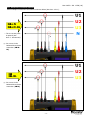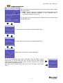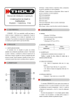
1
Man. NVIP3 – Rel. 1.3 EN (UK) USER MANUAL Man. NVIP3 – Rel 1.3 EN (UK) Congratulations on having chosen NanoVIP3, a product based on Elcontrol's 50 years of experience in the control of power consumption. High technological content, careful material selection, and full compliance with the latest regulations, make this product the only one of its kind. NanoVIP3 has been designed, built and tested in Italy. It complies with all qualitative requirements for European products regarding the environment, safety and work ethics. -2- Man. NVIP3 – Rel 1.3 EN (UK) TABLE OF CONTENTS Page 1 2 3 4 5 Presentation 1.1 Intended Use Safety 2.1 Operators' Safety 2.2 EC, RoHS & WEEE Declaration of Conformity 2.3 Reference Standards 2.4 Warranty Conditions Description & Connection to the Electrical System 3.1 Power Supply 3.2 USB Port 3.3 Memory Card (uSD) 3.4 Electrical Connection Schemes Start Up 4.1 User Interface 4.1.1 Description of Setup & Measurement Menus 4.1.1.1 Bottom Bar 4.1.2 Keypad 4.2 Programming & Setup 4.2.1 Connections Setup 4.2.1.1 Type of Electrical Connection Setup 4.2.1.2 Type of Voltage & Voltage Ratio (VT) Setup for L1, L2, L3 4.2.1.3 Type of Voltage & Voltage Ratio (VT) Setup for U Aux 4.2.1.4 Cogeneration Setup 4.2.1.5 Zero Adjustment 4.2.1.6 Connection Check 4.2.2 Current Probes Setup 4.2.3 Setup of Minimum, Maximum & Average Values 4.2.3.1 Integration Time Setup 4.2.3.2 Reset of Average Values & Maximum Demand 4.2.3.3 Reset of Minimum & Maximum Values 4.2.4 Counters Reset 4.2.5 Language Setup 4.2.6 LCD Setup 4.2.6.1 Display Backlight Setup 4.2.6.2 Display Orientation Setup 4.2.6.3 Display Contrast & Brightness Setup 4.2.6.4 Menu Type Setup 4.2.7 Clock Setup 4.2.8 Bottom Bar Setup 4.2.9 Tariff Setup 4.2.9.1 Configuration & Resetting of Tariff 4.2.9.1.1 Selection of Days 4.2.10 EN 50160 Setup & Reset 4.2.11 Serial Communication Setup 4.2.11.1 Serial Communication Test 4.2.12 Alarm Setup & Reset 4.2.12.1 Alarm Configuration Instrument Use & Consultation 5.1 Scrolling through Measurement Menus 5.2 Three-phase or Two-phase Connection Menus 5.2.1 Voltages Menu 5.2.2 Currents Menu 5.2.3 Power Menu 5.2.4 Counters Menu 5.2.5 Harmonics Menu 5.2.5.1 Consulting Harmonic Histograms 5.2.6 Waveforms Menu -3- 5 5 7 7 7 8 9 10 10 11 11 12 15 15 15 16 16 17 19 19 19 19 19 19 19 20 20 20 20 21 21 21 21 21 22 22 22 22 22 23 23 23 24 24 24 25 25 26 26 32 32 33 34 36 38 40 41 6 7 8 9 5.2.7 Snapshot Function 5.2.8 EN 50160 Menu 5.2.9 Alarm Menu 5.2.10 Transient Menu 5.2.10.1 Transient Setup 5.2.10.1.1 Input Selection 5.2.10.1.2 Voltage Threshold 5.2.10.1.3 Current Threshold 5.2.10.1.4 In Threshold 5.2.10.1.5 Transient Detecting Mode 5.2.10.2 Inrush Current Setup 5.2.10.2.1 Input Selection 5.2.10.2.2 Current Threshold 5.2.10.2.3 Analysis Duration 5.2.10.2.4 Automatic Start 5.2.10.2.5 Manual Start 5.2.10.3 Inrush Current Display 5.2.11 Measurement Campaigns Menu 5.2.11.1 Measurement Campaigns 5.2.11.1.1 Campaign Name 5.2.11.1.2 Storing Rate 5.2.11.1.3 Manual Start 5.2.11.1.4 Scheduled Start 5.2.11.2 uSD Content 5.3 Single-phase Connection Menu 5.3.1 Voltages Menu (1ph) 5.3.2 Currents Menu (1ph) 5.3.3 Power Menu (1ph) 5.3.4 Counters Menu (1ph) 5.3.5 Harmonics Menu (1ph) 5.3.6 Waveforms Menu (1ph) Maintenance 6.1 Accuracy Control 6.2 Repair 6.3 Troubleshooting NanoStudio Software Technical Specifications Accessories & Spare Parts Man. NVIP3 – Rel 1.3 EN (UK) 42 42 43 43 44 44 44 44 44 44 45 45 45 45 45 46 45 46 46 46 47 47 47 47 48 48 48 48 50 51 53 54 54 54 54 55 56 59 60 Appendix 1 – Modbus Measurement Registers -4- Man. NVIP3 – Rel 1.3 EN (UK) 1 - PRESENTATION NanoVIP3 is a leading device equipped with new functions for measuring and monitoring power consumption and for advanced power and power quality analysis. This device can measure, display, process and transmit all the parameters of a system. With regard to the most common power analysers, its main unique features are as follows: new, modern, elegant design which makes this device a handheld product – and therefore, light and easyto-use – with the best performance in its category; Highly efficient 128x128 pixels backlit graphical LCD for high ductility display (multilingual menus, waveforms, histograms, menus, drawings, schemes, images customisation, etc.) and perfect viewing even from a distance; 4 voltage measuring channels (3 with common neutral + 1 auxiliary independent) up to 600V CAT III, able to measure continuous voltage with an accuracy of ±0.25% + SF err.; 5 current inputs (3 independent + 1 for neutral current + 1 auxiliary) able to measure continuous voltage with an accuracy of ±0.25+SF err.; Equipped with flexible current clamps up to 3000A. Traditional full scale sensors, which can be set by the user, may also be used. High performance battery pack with more than 24 hours of battery life, so that extended measurement campaigns can also be performed without using main power supply; Powerful but compact external power supply, compatible with all types of sockets (USA/JP, EU, UK, AU); Membrane keypad with 10 double-function keys for easier scrolling of menus and access to different functions; Calculation engine based on 16-bit microprocessor, allowing for the measurement of all standard quantities (V I P Q A F PF THD% etc.) in true root mean square (TRMS) value, as well as: ● Measurement of minimum, average and maximum instant values on 4 quadrants (absorbed and generated). ● Absorbed and produced power counters (kWh kVA kVAr), which can be password-protected. ● Power quality analysis by measuring: current and voltage harmonics (all 7 input channels) up to the 50th order; ● ● ● ● Network interruptions & micro-interruptions Dips (brownouts) Swells (overvoltages) EN50160 test (reference standard for power quality) Event log (last 5 alarms, 5 dips, 5 swells, 5 interruptions) Power measurement during 4 time periods (tariffs), which can be set For three-phase and each single phase!!! 6 different electrical systems which can be analysed (single-phase; two-phase; 3-lead three-phase (unbalanced); 4-lead three-phase (unbalanced); 3-lead three-phase (balanced); 4-lead three-phase (balanced). ● Medium voltage connection available User can select the values to be displayed. Multilingual menus (English, Italian, German, Spanish, French). Automatic connection test to check if electrical connections are correct. Micro SD memory card for extended measurement campaigns. Special PC software, allowing for advanced analysis of data stored on uSD card. 1.1 - Intended Use NanoVIP3 is a measuring tool designed for those in need of an accurate and easy-to-use product. It is aimed at both users who want to understand their systems better, and Energy Managers, system installers, electricians, and maintenance workers, for diagnosis and intervention, or for the provision of integral consulting services on electrical power. NanoVIP3 allows users to: • monitor loads, consumption and related costs; • check if the new systems are dimensioned correctly; • prevent overheating and lack of insulation due to high harmonics content; • solve any power factor correction problems; • identify and eliminate load peaks and excess demand, thereby reducing contractual power consumption; • monitor power and consumption in the different time bands; • check and assess the performance of UPSs, with AC/DC measurements; -5- • • • • Man. NVIP3 – Rel 1.3 EN (UK) measure signals - including asymmetrical signals - for PWM controls on inverters; identify the cause of problems resulting from low quality power (presence of harmonics, interruptions, overloads, dips, unbalance in voltage phases, etc.), which may bring about a production standstill, and which may affect or reduce the life cycle of equipment and systems; identify fast fluctuations and variations in current and voltage signals; measure inrush current of electrical engines and equipment. -6- Man. NVIP3 – Rel 1.3 EN (UK) 2 - SAFETY AND WARRANTY NanoVIP3 has been designed and tested in accordance with the latest directives in force, and complies with all technical and safety requirements. To preserve the product and ensure its safe operation, follow the instructions and the CE markings contained herein. CAUTION! Please read these instructions carefully before using the device! 2.1 - Operators' Safety ● ● ● ● ● ● The instrument described herein must only be used by trained personnel. Connection and maintenance operations must only be carried out by qualified and authorised personnel, as they may result in electrocution, burns or explosions. For the correct and safe use of the instrument, as well as for all installation and maintenance purposes, operators must always comply with standard safety procedures. The manufacturer shall in no way be liable if such procedures are not complied with. Before connecting the instrument to the electrical system, as well as before handling, maintaining or repairing the instrument, the instrument and the electrical cabinet to which it is connected must be disconnected from any voltage source. Before turning on the instrument, make sure the maximum voltage at the voltmeter inputs is 1000VAC phase/phase or 600VAC phase/neutral. If the instrument can no longer be operated safely, it must be discarded and measures must be taken to prevent accidental use. Safe operation is no longer possible in the following cases: ! if damage to instrument is clearly visible; ! if instrument is no longer working; ! after being stored for an extended period under unfavourable conditions; ! if instrument is badly damaged during transportation. The symbol shown here on the right - when found on the product or elsewhere - means that the user manual must be consulted. 2.2 - EC, RoHS & WEEE Declaration of Conformity Manufacturer: ELCONTROL ENERGY NET S.r.l. Via Vizzano 44 40044 Sasso Marconi (BO) - Italy Product: NanoVIP3 / NanoVIP2Power Analyser Directives complied with: Equipment); 93/68/EEC (Low Voltage Electrical 89/336/EEC and 2004/108/EC (EMC Electromagnetic Compatibility); 2006/95/EC - 72/23/EEC (LVD - Low Voltage Directive); 2002/95/EC (RoHS); 2002/96/EC and 2003/108/EC (WEEE). Year of mark affixing: 2012 Certificate: 12CDC27 by Lem S.r.l. Notified Body Reference standards applied for EC compliance: EN EN EN EN EN -7- 61010-1 61326 61326/A1 61326/A2 61326/A3 Man. NVIP3 – Rel 1.3 EN (UK) 2.3 - Reference Standards Standard EN 61010-1 EN 61326 Title Description Int. Link Safety requirements for electrical equipment for measurement, control, and laboratory use. General safety requirements for electrical equipment intended for professional, industrial process, and educational use. Electrical test and measurement, control, and laboratory equipment. Electrical equipment for measurement, control and laboratory use. EMC requirements. This Standard specifies the minimum requirements for immunity and emissions regarding electromagnetic compatibility (EMC) for electrical equipment, operating from a supply or battery of less than Identical to 1000 VAC or 1500 VDC, intended for professional, industrial-process, industrial- IEC 61326-1: 1997-03 manufacturing and educational use, EN 61326-1:1997-04 including equipment and computing EN 61326-1 Ec:1998-01 devices for measurement and test; control; laboratory use; accessories intended for use with the above equipment. Identical to IEC 61010-1:2001-02 EN 61010-1:2001-03 Electrical equipment for measurement, control and EN 61326/A1 laboratory use. EMC requirements. This amendment modifies the requirements for the immunity tests laid down in Standard IEC EN 61326 for the three specific applications specified Identical to below: Use in industrial environment; use in IEC 61326-1/A1: 1998-05 laboratories or test and measurement EN 1326/A1: 1998-06 areas with electromagnetically-controlled EN 61326-1 Ec:1998-09 environments; portable test and measurement equipment operating from a battery or from the circuit being measured. Electrical equipment for measurement, control and EN 61326/A2 laboratory use. EMC requirements. This amendment adds an annex to the basic Standard introducing more detailed specifications regarding test configurations, operating conditions, and Identical to performance criteria for certain equipment intended for applications IEC 61326-1/A2: 2000-08 where no special EMC requirements are EN 61326/A2: 2001-05 provided. Some examples of such equipment are: oscilloscopes, logic analysers, spectrum analysers, digital multimeters, etc. Electrical equipment for measurement, control and EN 61326/A3 laboratory use. EMC requirements This amendment to IEC EN 61326 (IEC 65-50) adds regulatory Annexes E & F to Identical to: the basic Standard, regarding test configurations, operating conditions, and IEC 61326:2002-02 performance criteria for portable test, (Annex E & F); measurement and monitoring equipment IEC 61326/Ec1:2002-07 which are used in low voltage distribution EN 61326/A3:2003-12 systems. -8- Man. NVIP3 – Rel 1.3 EN (UK) 2.4 - Warranty Conditions WARRANTIES AND DISCLAIMERS 3 Elcontrol guarantees that each NanoVIP is free of defects, complies with technical specifications, and is suitable for the purposes declared by Elcontrol for a period of twelve (12) months from the documented purchase date or, in the absence of said date, the date of calibration. The warranty covers faulty hardware parts, but not software, consumables and labour and transport costs. Repairs under warranty shall only be performed if Elcontrol actually finds manufacturing defects or poor material quality. The warranty shall no longer be valid if the defect is due to: incorrect electrical power supply, swells, improper connections, tampering, repairs or modifications carried out without the prior consent of the manufacturer, accidents or use other than that described herein. Damage resulting from disuse or any harm caused to third parties shall not be covered. Faulty products must be returned to the importer/distributor in your country or to Elcontrol DELIVERED DUTY PAID, subject to prior consent of Elcontrol. A request for repair under warranty shall be accompanied by proof-of-purchase, stating the date on which the product was purchased. The warranty shall not be valid for products which have not been paid by the purchaser by the agreed deadline, as well as if the faulty product is returned from a country other than that where the product was sold, unless otherwise agreed. DEFECT REPORT Any defect reports regarding delivered products - whether apparent or latent - shall be submitted to Elcontrol in writing. The purchaser can in no way return the products without the prior consent of Elcontrol or following the decision of the judicial authorities. Products must be returned within ten (10) days of the consent of Elcontrol or the judicial authorities. In the event of a report - regardless of the object and reason therefore - the purchaser shall pay the full amount indicated on the invoice. If the delivered products have been modified, altered or used by the purchaser, no report shall be accepted or deemed valid. Discrepancies which are deemed customary in trade, as well as discrepancies which cannot be technically avoided, especially those concerning quality, colours, manufacturing processes, drawings and similar aspects, cannot be the object of a claim. Elcontrol reserves the right to make any changes to its products without altering their quality or performance. Such changes cannot be the object of a claim. Whenever Elcontrol receives a claim regarding the condition of a product, quality defects or non-compliance with technical specifications, Elcontrol shall have the right - in its sole discretion - to replace the products without any charge, repair the products or issue a credit note. Any kind of damage is excluded. In case of interventions under the warranty period, all shipping costs for repairing and/or replacing the faulty products shall be borne by the purchaser. LIMITATION OF LIABILITY Except for the warranty, Elcontrol shall in no way be liable for any direct or indirect damage incurred by the purchaser, such as – but not limited to – material damage, damage for loss in profit and loss, damage to purchaser's documents, archives or data, damage for third party claims, and damage claimed by any party whatsoever, resulting from applications obtained by the purchaser for himself or third parties, with the help – or the use – of products purchased from Elcontrol. FINAL PROVISIONS The warranty conditions described herein supersede and void any other obligations and warranties which 3 the parties may have agreed upon – both orally and in writing – before the purchase of NanoVIP . Therefore, any such obligations or warranties shall be deemed void and invalid. -9- Man. NVIP3 – Rel 1.3 EN (UK) 3 - DESCRIPTION & CONNECTION TO THE ELECTRICAL SYSTEM NanoVIP3 is designed to carry out both real time measurements and extended measurement campaigns. It is equipped with shockproof, anti-slip rubber details which make it easy to hold with one or both hands, and a support which allows the user to place the instrument on a level surface. NanoVIP3 has to be connected to the electrical system by means of special voltage and current inputs. The figure below shows the 3 voltage channels U1, U2 and U3, with common neutral (N), and the 4 independent current channels I1, I2, I3, In. The initials below the inputs help the user identify them. CURRENT INPUTS VOLTAGE INPUTS (600V CAT III) The voltage cables - which come with the instrument - are connected to the voltage inputs. Make sure the cables are connected to the corresponding colours. Alternatively, any cable with a blade plug connector, ∅4mm and certified for at least 600V CAT III, may be connected. The current inputs can be connected to the flexible current mini-clamps, which come with the instrument and are marked with special coloured rings, which correspond to the different phases. Alternatively, other Elcontrol Energy Net amperometric probes may be used, depending on the specific measurement requirements. For more details, read Sect. 9 – Accessories & Spare Parts. An independent, auxiliary voltage input (UAUX) and an independent, auxiliary current input (IAUX) are also available. The cables and current sensor for such channels are optional (see Sect. "ACCESSORIES"). 3.1 - Power Supply NanoVIP3 is equipped with an external power supply which can be connected to any socket (USA/JP, UK, EU, AU) with voltage 100÷240V~ ±10% and frequency 47÷63 Hz. The output jack of the power supply is to be connected to the special 7.5VDC connector of the device. The instrument is also equipped with a NiMh rechargeable battery pack, which guarantees more than 24 hours of use, without you having to connect it to the main line. Batteries are recharged by an external power supply, which is supplied with the instrument. Batteries cannot be recharged through the USB connection. If NanoVIP3 is not used for a long period of time, then perform a charge cycle every two months (approximately) to prevent the batteries from going almost completely flat, in which case you will no longer be able to recharge them. - 10 - Man. NVIP3 – Rel 1.3 EN (UK) 3.2 - USB Port NanoVIP3 can be connected to a PC through the USB port and the cable supplied. This connection allows the user to download the MODBUS measurement registers using the PC Energy Studio Manager software. The USB communication may also allow easy upgrade of the firmware (internal software) of the instrument. NOTE: If the PC does not automatically detects NanoVIP3 as a device, download or update the appropriate drivers at www.ftdichip.com/Drivers/VCP.htm 3.3 - Memory Card NanoVIP3 is equipped with a slot for a 2 GB uSD memory card, which can be used to store measurement campaigns data (Sect. 5.2.11.2), fast transients (Sect. 5.2.10.1) and inrush currents (Sect. 5.2.10.2). uSD Card SLOT The memory card must be inserted as shown in the figure on the left, with the contacts facing up. NOTES: The slot is push-push type (the card is both inserted and removed by pressing it). Do not try to remove the card by pulling it, as this will damage the connector. Do not remove the uSD card whilst a measurement campaign is being performed, as all data will be lost. The uSD card is supplied with the instrument, together with the: • User Manual • PC software (See software manual for use) - 11 - Man. NVIP3 – Rel 1.3 EN (UK) 3.4 - Electrical Connection Schemes Some examples of electrical connections are shown below (See Sect. 4.2.1.1). 3Φ Φ+N 3Φ Φ+N-BL (1) (1) * The 4th current probe is optional (See Sect. 9 - Accessories) (1) Do not use in the balanced three-phase connection (3Φ Φ+NBL) 3Φ Φ 3Φ Φ-BL (1) (1) (1) Do not use in the balanced three-phase connection (3Φ Φ-BL) - 12 - Man. NVIP3 – Rel 1.3 EN (UK) 2Φ Φ * The probe for measuring the neutral current is optional. 1Φ Φ - 13 - Man. NVIP3 – Rel 1.3 EN (UK) Dispersion Measurement I (can be combined with the previous schemes) * LMA clamp is optional (See Sect. 9 – Accessories) Example of connection on inverter * DC clamp and additional voltage cables are optional - 14 - Man. NVIP3 – Rel 1.3 EN (UK) 4 - START-UP Before using NanoVIP3 the correct configuration must be done, depending on the type of installation and system to which it will be connected. Make sure the electrical cabinet is off before connecting the instrument. Once the connection is complete, switch on the electrical cabinet and the instrument by pressing and holding down the POWER key for approximately 3 seconds (the same action switches off the instrument). At start-up, the following screen will be displayed for a few seconds: ● product model; ● software version; ● serial number. 4.1 - User Interface For easy use, NanoVIP3 is equipped with a graphic LCD and a membrane keypad with snap domes for tactile feedback, described in detail in Sect. 4.1.2. The software architecture of the instrument is divided into MENUS, more specifically SETUP and MEASUREMENT Menus. Each menu consists of a number of pages, which are described in the following section. 4.1.1 - Description of Setup & Measurement Menus A typical SETUP Menu consists of: ● a heading showing the name/title of the screen; ● an area with the fields to be selected - and possibly modified - by means of the cursor. A typical MEASUREMENT Menu consists of: ● a heading showing the name/title of the screen; ● an area displaying related parameters (See NOTE); ● an area displaying the main parameters; ● a bottom bar displaying alternating information (See Sect. 4.1.1.1) - 15 - Man. NVIP3 – Rel 1.3 EN (UK) NOTE: based on the type of menu, the area of related parameters and/or the bottom bar may not be displayed. 4.1.1.1 - Bottom Bar This area displays information regarding the status of the instrument, such as: 4) Type of electrical connection 1) Battery level 2) MicroSD card 3) Measurement campaign 1) Indicates battery life 2) Indicates whether or not a memory card has been inserted 3) Indicates whether or not a measurement campaign is being performed or is scheduled, according to the methods described in Sect. 5.2.10 4) Indicates the type of electrical connection selected (Sect. 4.2.1.1) In addition to the above information, the bottom bar will alternate between 3 parameters of the user's choice (Sect. 4.2.8). 4.1.2 - Keypad The NanoVIP3 keypad is equipped with 9 doublefunction keys, i.e. the function of each key varies depending on whether it is pressed once or pressed and held for approximately 3 seconds. Specifically, the functions represented by the icons on the black background (V, I, P, , , , , , ) are activated by pressing the relevant key, whereas the functions represented by the icons on the white background (€, , , , 50160, , , , ) are activated by pressing and holding down the relevant key. Therefore, the instrument has 12 function keys, a joystick with the Enter function and arrow keys, and a key to access the Setup Menu directly, which allow for a more immediate and effective use of the instrument. The Power ( ) key must also be pressed for approximately 3 seconds to be activated. Moreover, when an alphanumerical value in a field in the Setup Menu must be changed (Sect. 4.2), pressing and holding down the or keys will accelerate scrolling, so that the desired value can be reached faster and easier. NOTE Each key is made of a special metal dome. The "click" which can be heard when pressing a key confirms contact. This technology is more reliable than the classic membrane with embossed keys. However, avoid pressing the keypad too hard, as this may cause damage or the keypad to malfunction. The use of the keypad can easily be learnt through the Setup Diagrams (Sect. 4.2) and Measurement Diagrams (Sect. 5.1). The table below provides a general description of the keys. - 16 - Man. NVIP3 – Rel 1.3 EN (UK) FUNCTION KEY Press Once Press and Hold for 3 seconds Switch the instrument ON and OFF Access to VOLTAGES Menu Access to COUNTERS Menu Access to CURRENTS Menu Access to HARMONICS - THD - Cosϕ Menu Access to POWER Menu Access to WAVEFORMS Menu Snapshot Function: Takes a snapshot of the parameters and displays them for the desired period of time. Access to MEASUREMENT CAMPAIGN Menu • • Access to AUX channel. After pressing , scrolls through the harmonics, trends, dips, interruptions, and alarms menus. Access to PHOTOVOLTAIC (if enabled) • • • Scrolls down the pages of a measurement menu. Moves cursor down in the setup pages. Decreases the selected value in the setup pages. Access to TRANSIENTS Menu • • Exits AUX channel. After pressing harmonics, trends, alarms menus. Access to ALARMS Menu • • • Scrolls up the pages of a measurement menu. Moves cursor up in the setup pages. Increases the selected value in the setup pages. Access to EN 50160 Menu • Selects a parameter to be modified in the setup pages. Access to a measurement subpage or submenu. In this case, ENTER will be displayed in the lower right corner of the display. Access to SETUP Menu • , scrolls through the dips, interruptions, and 4.2 - Programming & Setup Press for approximately 3 seconds to access the configuration menus. Use and keys to select the parameter to be configured. Press and the cursor will start to flash. Use and keys to modify the selected value. Press again to confirm the value. The cursor will stop flashing. Press and ⊳ to scroll through the setup pages, as illustrated in the flowchart below. As shown in the flowchart, the menus have a loop-type structure, i.e. when the end of the last page is reached, the menu automatically returns to the first page. You can scroll through the menus in either direction. - 17 - Flowchart of Setup Menu CONNECTIONS SETUP (4.2.1) Man. NVIP3 – Rel 1.3 EN (UK) AMPEROMETRIC SENSORS SETUP (4.2.2) MINIMUM, MAXIMUM & AVERAGE SETUP (4.2.3) LCD SETUP (4.2.6) CLOCK SETUP (4.2.7) COUNTERS SETUP (4.2.4) (3”) LANGUAGE SETUP (4.2.5) TARIFFS SETUP (4.2.9) EN50160 SETUP (4.2.10) COMMUNICATION SETUP (4.2.11) BOTTOM BAR SETUP (4.2.8) ALARMS SETUP (4.2.12) TARIFF SETUP (4.2.9.1) COMMUNICATION TEST (4.2.11.1) To exit the SETUP Menu, press page. TARIFF DAYS SETUP (4.2.9.1.1) CONNECTION CHECK (4.2.1.6) ZERO ADJ (4.2.1.5) - 18 - ALARM 1 & 2 SETUP (4.2.12.1) for approx. 3 seconds on any Man. NVIP3 – Rel 1.3 EN (UK) 4.2.1 - Connections Setup This menu allows the user to: ● ● ● ● ● ● Set the type of electrical network to which the instrument is connected (Sect. 4.2.1.1). Set the type of voltage and voltage ratio for phases L1, L2, and L3 (Sect. 4.2.1.2). Set the type of voltage and voltage ratio for U AUX (Sect. 4.2.1.3). Activate/deactivate measurements in cogeneration mode (Sect. 4.2.1.4). Automatically adjust the zero level of measuring channels (Sect. 4.2.1.5). Check if the instrument and relevant probes are connected to the electrical system correctly (Sect. 4.2.1.6). 4.2.1.1 - Type of Electrical Connection Setup To set the type of connection, enter the CONNECTIONS SETUP Menu, place the cursor on GRID TYPE and select one of the following options (See Sect. 3.2): ● ● ● ● ● ● 3PH+N-BL 3PH-BL 3PH 3PH+N 2PH 1PH = = = = = = balanced three-phase system with neutral (Page 12) balanced three-phase system without neutral (Page 12) unbalanced three-phase system without neutral (Page 12) unbalanced three-phase system with neutral (Page 12) two-phase system (Page 13) single-phase system (Page 13) 4.2.1.2 - Type of Voltage & Voltage Ratio (VT) Setup for L1, L2, L3 phases NanoVIP3 can measure both alternate and direct current. The user must set the type of voltage to be analysed, selecting AC (alternate current) or DC (direct current). When a voltmeter transformer has to be connected, i.e. when voltages higher than 600VAC must be measured, the corresponding transformation ratio must be set (default value = 1), changing the values as needed (1 to 60000). 4.2.1.3 - Type of Voltage & Voltage Ratio (VT) Setup for U AUX As described in the previous section, the same settings can be applied to the auxiliary voltage channel U Aux. 4.2.1.4 - Cogeneration Setup NanoVIP3 can also be configured to measure the power and energy that might be generated. To do so, place the cursor on GENERATION and select ON. By selecting OFF, the instrument will stop measuring the power generated, which will be considered absorbed power. NOTE: when changing from Generation ON to Generation OFF, the counters of generated power are not reset. 4.2.1.5 - Zero Adjustment After disconnecting the voltage and current input channels from the measuring grid, place the cursor on START and press to correct the offset, in case the latter has deviated. A page with numerical values will be displayed for the duration of the zero adjustment procedure (10-20”). When the procedure is complete, the system will automatically return to the CONNECTIONS SETUP page. 4.2.1.6 - Connection Check Once the instrument has been configured and connected to the system, the instrument can check if the connection to the electrical system has been performed correctly (to perform this check, the PF value must comply with the value indicated on the screen). Place the cursor on Connection Check and press to perform the check. The related outcome will then be displayed. - 19 - Man. NVIP3 – Rel 1.3 EN (UK) • • • Voltage phase sequence Threshold of the measured PF which allows for a correct analysis (if the PF is lower than the value indicated, the check cannot provide valid information) Check of the correspondence between voltage and current of each phaseand possible error message: Ok = Connection is correct Invert CT = Invert the direction of the current clamp indicated Failed = No correspondence between voltage and current or the PF value is lower than the threshold displayed Select "Repeat" to perform a new check. Select "Exit" to return to the CONNECTIONS SETUP page. 4.2.2 - Current Probes Setup This page allows the user to select: ● ● ● ● ● ● the type of probe used for I1, I2, I3, i.e. Flex (non-amplified flexible sensors) or AC/DC (clamp); the sensor transformation ratio on I1, I2, I3 (press and hold down or to increase scrolling speed); the type of probe used for In, i.e. Flex (non-amplified flexible sensor) or AC/DC (clamp); the sensor transformation ratio on In (press and hold down or to increase scrolling speed); the type of probe used for Iaux, i.e. Flex (non-amplified flexible sensor) or AC/DC (clamp); the sensor transformation ratio on Iaux (press and hold down or to increase scrolling speed). 4.2.3 - Minimum, Maximum & Average Setup This page allows the user to: ● Set the integration time, i.e. the time at which the average values and maximum demand are calculated. ● Reset the average values and maximum demand. ● Reset the minimum peaks and maximum instant values. 4.2.3.1 - Integration Time Setup To set the integration time, place the cursor on INTEGR. TIME and select the desired time, which is expressed in minutes (default value = 15 min). 4.2.3.2 - Reset of Average Values & Maximum Demand To reset the average values and maximum demand, place the cursor on AVG RESET and select YES. - 20 - Man. NVIP3 – Rel 1.3 EN (UK) 4.2.3.3 - Reset of Minimum & Maximum Values To reset the minimum and maximum instant values, place the cursor on RESET MIN MAX and select YES. 4.2.4 - Counters Reset To reset the counters of both absorbed and generated power, place the cursor on COUNTERS RESET and select YES. N.B. To reset the tariff counters, see Sect. 4.2.9.1 4.2.5 - Language Setup Select one of the following languages: ● ● ● ● ● ENGLISH ITALIANO ESPAÑOL FRANÇAIS DEUTSCH 4.2.6 - LCD Setup The LCD SETUP page allows the user to set: ● The backlight of the display (Sect. 4.2.6.1). ● LCD orientation (Sect. 4.2.6.2). ● LCD contrast level (Sect. 4.2.6.3). ● The display brightness (Sect. 4.2.6.3). ● The menu type (Sect. 4.2.6.4). 4.2.6.1 - Backlight Setup The LCD SETUP page allows the user to set backlight of the display. Place the cursor on BACKLIGHT and select: ● ALWAYS ON. ● DELAY OFF 15 SEC (the backlight dims 15 seconds after the last key was pressed). ● DELAY OFF 1 MIN (the backlight dims 1 minute after the last key was pressed). - 21 - Man. NVIP3 – Rel 1.3 EN (UK) Obviously, with time, LCD efficiency will depend on the number of hours of operation and the level of brightness selected (Sect. 4.2.6.3). Therefore, unless strictly necessary, we advise against the level of brightness being higher than 70 and keeping the backlight ALWAYS ON. NOTE: The display turns on automatically if an alarm goes off (See Sect. 4.2.11.1). 4.2.6.2 - Display Orientation Setup In particular situations, changing the display orientation may be practical, e.g. when the instrument must be placed in a vertical position. This function allows the user to rotate the LCD by 90° with respect to the default setting. 4.2.6.3 - Contrast & Brightness Setup To adjust the contrast and brightness of the display - so as to increase or decrease display efficiency and better adapt the instrument to different environmental conditions - place the cursor on CONTRAST or BRIGHTNESS and increase or decrease the parameters by increasing or decreasing the relevant values. 4.2.6.4 - Menu Type Setup Despite its easy-to-use interface, NanoVIP3 can perform a great number of measurements, and features many functions. If the user only needs a limited number of functions or measurements, this feature may sometimes be superfluous. Therefore, to make using the instrument even easier, two different types of menus have been provided: ● The FULL Menu, which includes all the screens (See Sect. 5). ● The PARTIAL Menu, which only displays the Voltage, Currents, Power, Storage, and Setup Menus, making it less exhaustive but quicker to use. NOTE: the Partial Menu only affects the displayed information. All data are always stored. If the user subsequently selects the Full Menu, the analyses performed in the previously disabled menus will also be displayed. 4.2.7 - Clock Setup. This page allows the user to set the date and time. The format is DD/MM/YYYY 4.2.8 - Bottom Bar Setup This page allows the user to choose the 3 parameters (out of 63) to be displayed alternately in the bottom part of the measurement screens, in addition to the battery level. The following parameters are available: Vrms 3F, Vrms L1, Vrms L2, Vrms L3, Irms 3F, Irms L1, Irms L2, Irms L3, Prms 3F, Prms L1, Prms L2, Prms L3, Qrms 3F, Qrms L1, Qrms L2, Qrms L3, Srms 3F, Srms L1, Srms L2, Srms L3, pf 3F", pf L1, pf L2, pf L3, thdv 3F, thdv L1, thdv L2, thdv L3, thdi 3F, thdi L1, thdi L2, thdi L3, KWh+3F, KWh L1, KWh L2, KWh L3, KVArh+3F, KVArhL1, KVArhL2, KVArhL3, KWh-3F, KVArh3F, KWh+F1, KWh+F2, KWh+F3, KWh+F4, Clock, Freq, In, Unbal, n.dip, n.swell, n.int, Vaux, Iaux, Paux, Qaux, Saux, PFaux, FRaux, CosPhi L1, CosPhi L2, CosPhi L3. NOTE: to display only one parameter, select the same parameter for all 3 options. - 22 - Man. NVIP3 – Rel 1.3 EN (UK) 4.2.9 - Tariffs Setup Choose the tariff band to be set by selecting it with the cursor. Then press to access the relevant configuration and reset the submenu (Sect. 4.2.9.1). ● This function resets the measurements previously performed (for all 4 tariffs). The following options are available: NEVER - 1 MONTH 2 MONTHS - 3 MONTHS 4.2.9.1 - Configuration and Resetting of Tariff This page allows the user to set the following parameters for each tariff: ● start time (with 15 minute intervals); ● end time (with 15 minute intervals); ● ● access to the subpage to select the days on which the tariff is to be applied (Sect. 4.2.9.1.1); the cost of the kWh consumed (in the relevant currency); ● the yield of the kWh generated (in the relevant currency); ● return to the "Tariffs Setup" page (Sect. 4.2.9). NOTE: do not cause the time of the different tariff bands to overlap. When the time of a tariff is changed, always make sure that it does not overlap with the time of another tariff. To set 12:00 am, select 0:00. 4.2.9.1.1 - Selection of Days This page allows the user to set the days on which the tariff will be active. To do so, select the day to be enabled/disabled and press ⊳ or to change its status. Select “Exit” and press 4.2.9.1). - 23 - to return to the “Tariff Setup” page (Sect. Man. NVIP3 – Rel 1.3 EN (UK) 4.2.10 - EN 50160 Setup & Reset As described in Standard EN 50160, the phenomenon “voltage disturbances” (swells, dips, interruptions, etc.) does not feature standard values by means of which power quality can be evaluated. Therefore, it is the user's responsibility to evaluate whether the voltage disturbances of the system are actually harmful or if they can be disregarded, based on the type of installation, production, connected instrument, etc. The EN 50160 SETUP page allows the user to set the values necessary for performing the 50160 TEST correctly (Sect. 5.1.7), i.e. for evaluating the power quality of the system. Specifically, the following parameters can be set: ● Vrms value below which an interruption is defined; ● Vrms value below which a dip is defined; ● Vrms value above which a swell is defined; ● Nominal voltage; ● Nominal frequency; ● Reset the stored data related to all the grid disturbances that have been recorded. 4.2.11 - Serial Communication Setup This page allows the user to set the following parameters: • ● Data transfer speed (baud rate): 4800, 9600, 19200, 38400, 57600, 115200 bps. Type of parity: no parity, even, or odd; ● Protocol type: BCD or IEEE; ● Address of the instrument (which must be unique) if the latter is connected to a PC with Energy Studio Manager monitoring software; Press to access the communication test page (Sect. 4.2.12.1). ● NOTE: to consult the Modbus registers, see Appendix 1 attached hereto. 4.2.11.1 - Serial Communication Test This page is helpful when connecting the instrument to a PC to check if communication is correct, as well as to check if the instrument is working correctly. • This field shows the current status (No communication, Comm. OK) or the type of error (checksum error, framing error, etc.) occurring during communication. • Return to the "Communication Setup" page (Sect. 4.2.12). NOTE: in case of a permanent error, check that the parameters have been configured correctly (PC and instrument) - 24 - Man. NVIP3 – Rel 1.3 EN (UK) 4.2.12 - Alarm Setup & Reset Two alarms can be set and configured with NanoVIP3. ● Place the cursor on either alarm and press relevant configuration submenu. • Select ALARM RESET and choose YES to reset all the stored alarms that can be viewed in the Alarm Menu (Sect. 5.2.8). ● In the Alarm 1 or 2 configuration submenu, select OFF to disable the alarm or set the desired parameter to enable the alarm. The following parameters are available: Vrms 3F, Vrms L1, Vrms L2, Vrms L3, Irms 3F, Irms L1, Irms L2, Irms L3, Prms 3F, Prms L1, Prms L2, Prms L3, Qrms 3F, Qrms L1, Qrms L2, Qrms L3, Srms 3F, Srms L1, Srms L2, Srms L3, pf 3F, pf L1, pf L2, pf L3, thdv 3F, thdv L1, thdv L2, thdv L3, thdi 3F, thdi L1, thdi L2, thdi L3, Freq, In, Unbal, Vaux, Iaux, Paux, Qaux, Saux, PFaux, FRaux, CosPhi L1, CosPhi L2, CosPhi L3. Set the minimum threshold value. Set the maximum threshold value. Set the hysteresis percentage (valid for both the minimum and maximum threshold). Set the number of events after which the alarm should go off. Return to the "Alarm Setup & Reset" page to access the ● ● ● ● ● 4.2.12.1 - Alarm Configuration ● ● ● ● ● NOTE: if one of the alarms set goes off, it will be indicated in the bottom bar of the measurement pages, where the alarm will be displayed permanently (scrolling through measurements, as described in Sect. 4.2.8, will stop) until it is cleared. The last 5 alarms which have gone off are stored and can be displayed in the relevant menu (Sect. 5.2.8). - 25 - Man. NVIP3 – Rel 1.3 EN (UK) 5 - INSTRUMENT USE & CONSULTATION The NanoVIP3 keypad allows the user to access all the menus of the instrument directly, thanks to its practical function keys. Press the desired key to access the relevant menu. Use the arrow keys to scroll through the different pages of a menu. NanoVIP3 features the following Measurement Menus: 1) VOLTAGES Menu (V): press key once to access menu 2) CURRENTS Menu (I): press key once to access menu 3) POWER Menu (P): press key once to access menu 4) COUNTERS Menu (€): press and hold key down for 3” to access menu 5) HARMONICS Menu ( ): press and hold key down for 3” to access menu 6) WAVEFORMS Menu ( ): press and hold key down for 3” to access menu. 7) AUX CHANNEL Menu ( ): press key once to access menu. 8) SNAPSHOT Function ( ): press key once to access menu. 9) EN 50160 Menu (50160): press and hold key down for 3” to access menu. 10) ALARMS Menu ( ): press and hold key down for 3” to access menu. 11) TRANSIENTSMenu ( ): press and hold key down for 3” to access menu. 12) MEASUREMENT CAMPAIGNS Menu ( ): press and hold key down for 3” to access menu. 5.1 - Scrolling through Measurement Menus When accessing a measurement menu, the first page of the selected menu is displayed. Press or to scroll through the pages of the menu up and down, respectively. In the Voltage, Currents, Power, Counters, Harmonics, and Waveforms Menus, press to access the relevant Auxiliary Channel Menu. Use and arrows to scroll the relevant auxiliary channel menu. Press ⊳ to exit the auxiliary channel menu. Certain pages (e.g. harmonic histograms) allow the user to access internal sub-functions by pressing . The flowcharts of measurement menus are shown below. NOTE: entire menus or specific pages/parameters may not be displayed or changed, depending on the menu type which has been set in the LCD configuration (FULL or PARTIAL - See Sect. 4.2.6.4) and/or the type of electrical connection (e.g. if the single-phase connection has been set, the screens regarding three-phase data will not be displayed, and the structure of many other pages will be modified). - 26 - Man. NVIP3 – Rel 1.3 EN (UK) Flowchart of MEASUREMENT MENUS in THREE-PHASE WITH NEUTRAL connection. VOLTAGES MENU (Sect. 5.2.1). AUX CH. (V) CURRENTS MENU (Sect. 5.2.2). AUX CH (I). POWER MENU (Sect. 5.2.3). AUX CH. (P) x3” COUNTERS MENU (Sect. 5.2.4). AUX CH. (€) x3” HARMONICS MENU (Sect. 5.2.5). AUX CH. (HARMO) - 27 - Man. NVIP3 – Rel 1.3 EN (UK) x3” WAVEFORMS MENU (Sect. 5.2.6). AUX CH. (WAVEFORMS) AUX CHANNEL MENU VOLTAGES MENU CURRENTS MENU POWER MENU x3” COUNTERS MENU x3” HARMONICS MENU x3” WAVEFORMS MENU x3” EN 50160 MENU (Sect. 5.2.8). - 28 - Man. NVIP3 – Rel 1.3 EN (UK) x3” ALARMS MENU (Sect. 5.2.9). x3” TRANSIENTS MENU (Sect. 5.2.10) x3” MEASUREMENT CAMPAIGNS (Sect. 5.2.11) - 29 - Man. NVIP3 – Rel 1.3 EN (UK) Flowchart of MEASUREMENT MENUS in SINGLE-PHASE connection. VOLTAGES MENU (Sect. 5.3.1). CURRENTS MENU (Sect. 5.3.2). POWER MENU (Sect. 5.3.3). x3” x3” COUNTERS MENU (Sect. 5.3.4). HARMONICS MENU (Sect. 5.3.5). - 30 - Man. NVIP3 – Rel 1.3 EN (UK) x3” x3” WAVEFORMS MENU (Sect. 5.3.6). EN 50160 MENU (Sect. 5.2.8). x3” ALARMS MENU (Sect. 5.2.9). x3” TRANSIENTS MENU (Sect. 5.2.10) x3” MEASUREMENT CAMPAIGNS (Sect. 5.2.11) - 31 - Man. NVIP3 – Rel 1.3 EN (UK) 5.2 - Three-phase or Two-phase Connection Menu When switching on the instrument or exiting the Setup Menu, NanoVIP3 displays the first page of the Voltages Menu. As shown in the flowcharts, the menus have a loop-type structure, i.e. when the end of the last page is reached, the menu automatically returns to the first page. You can scroll through the menus in either direction. The information displayed will then vary, depending on the type of connection that has been set in the Setup Menu. 5.2.1 - Voltages Menu If the 3PH+N, 3PH+N-BL or 2PH connection is set (unbalanced/balanced three-phase with neutral connection or two-phase connection - See Sect. 4.2.1.1), the first page will display the phase-neutral voltages, the relevant phase currents, and the three-phase (or twophase) voltage. NOTE: if another type of electrical connections without neutral is set, this page will not be displayed. When scrolling through the pages of this menu, as described in Sect. 5.1, the following pages will be displayed. Line voltages and relevant phase currents. Frequency (measured on L1) and unbalance. NOTE: in a three-phase system, the unbalance value is a parameter indicating a condition in which the effective values of phase voltages or the phase angles between consecutive phases differ. This parameter is one of the values which serve as an indication of power quality. The lower the percentage value, the better the power quality. Average voltage levels (calculated on the basis of the integration time which has been set. Values can be reset as described in Sect. 4.2.3). Minimum instant voltage values (Values can be reset as described in Sect. 4.2.3.3) - 32 - Man. NVIP3 – Rel 1.3 EN (UK) Maximum instant voltage values (Values can be reset as described in Sect. 4.2.3.3) On any of the Voltages Menu pages, press to access the page containing all the information regarding auxiliary channel voltage. In the AUX Menu, the user can also access the other Auxiliary Channel Menus (Currents, Power, Counters, Harmonics, Waveforms) by selecting them with the relevant function keys. Press ⊳ to exit the Auxiliary Menu and return to the first page of the relevant menu. 5.2.2 - Currents Menu The first page of this menu displays the currents in each phase, as well as in the threephase current (or two-phase current, depending on the electrical connection) and corresponding voltages. When scrolling through the pages as described in Sect. 5.1, the following pages will be displayed. Neutral current or, in general, 4th current channel. NOTE: if a connection other than 3PH+N or 3PH+N-BL (unbalanced or balanced threephase with neutral - see Sect. 4.2.1.1) is used, the value will always be 0.000 Average current values in each phase (calculated on the basis of the integration time set. Values can be reset as described in Sect. 4.2.3). Minimum instant current values in each phase (values can be reset as described in Sect. 4.2.3.3). - 33 - Man. NVIP3 – Rel 1.3 EN (UK) Maximum instant current values in each phase (values can be reset as described in Sect. 4.2.3.3) Load peaks, i.e. the highest average current (calculated on the basis of the integration time set. Values can be reset as described in Sect. 4.2.3.2) On any of the Currents Menu pages, press to access the page containing all the information regarding the auxiliary channel current. In the AUX Menu, the user can also access the other Auxiliary Channel Menus (Voltages, Power, Counters, Harmonics, Waveforms) by selecting them with the relevant function keys. Press ⊳ to exit the Auxiliary Menu and return to the first page of the relevant menu. 5.2.3 - Power Menu The first page of this menu displays the active power (W) in each phase and in the threephase (or two-phase) connection and the corresponding PF values. NOTE: as a norm, active power is shown as a negative when generated and a positive when absorbed. When scrolling through the pages of this menu, as described in Sect. 5.1, the following pages will be displayed. Reactive power (Var) in each phase and in the three-phase (or two-phase) connection and the corresponding PF values. NOTE: as a norm, reactive power is shown as a negative when capacitive and a positive when inductive. Apparent power (VA) in each phase and in the three-phase (or two-phase) connection and the corresponding PF values. - 34 - Man. NVIP3 – Rel 1.3 EN (UK) PF values in each phase and in the three-phase (or two-phase) connection and the relevant type (Ind = Inductive load; Cap = Capacitive load) NOTE: the PF is always positive. As a norm, it is shown as a negative when active power is generated and a positive when absorbed. Average total power and PF (calculated on the basis of the integration time set. Values can be reset as described in Sect. 4.2.3). Minimum instant values of total power and PF (values can be reset as described in Sect. 4.2.3.3) Maximum instant values of total power and PF (values can be reset as described in Sect. 4.2.3.3) Load peaks and relevant PF, i.e. the highest average power (calculated on the basis of the integration time set. Values can be reset as described in Sect. 4.2.3.2) On any of the Power Menu pages, press to access a series of pages containing all the information regarding auxiliary channel power. The first page displays active, reactive and apparent power, as well as the PF. Use and arrows to scroll through the pages (See below). In the AUX Menu, the user can also access the other Auxiliary Channel Menus (Voltages, Currents, Counters, Harmonics, Waveforms), by selecting them with the relevant function keys. Press ⊳ to exit the Auxiliary Menu and return to the first page of the relevant menu. - 35 - Man. NVIP3 – Rel 1.3 EN (UK) Average power and PF (calculated on the basis of the integration time set. Values can be reset as described in Sect. 4.2.3) related to the auxiliary channel. Minimum instant values of power and PF (values can be reset as described in Sect. 4.2.3.3) related to the auxiliary channel. Maximum instant values of power and PF (values can be reset as described in Sect. 4.2.3.3) related to the auxiliary channel. Load peaks and relevant PF, i.e. the highest average power (calculated on the basis of the integration time set. Values can be reset as described in Sect. 4.2.3.2) related to the auxiliary channel. x3” 5.2.4 - Counters Menu The first page of this menu shows the counters of the active power absorbed (+kWh) in each phase and three- or two-phase connections. When scrolling through the pages as described in Sect. 5.1, the following pages will be displayed. The counters of the reactive power absorbed (+kVarh) in each phase and in three- or two-phase connections. - 36 - Man. NVIP3 – Rel 1.3 EN (UK) The counters of the apparent power (kVAh) in each phase and in the three- or two-phase connections. The counters of the active power generated (-kWh) in each phase and in three- or twophase connections. The counters of the reactive power generated (-kVarh) in each phase and in the three- or two-phase connections. The average PFs calculated as kWh/kVAh ratio (only the real part of the counters is taken into account; the decimal part is not considered). This page displays the absorbed and/or generated power, and the related costs for the time bands selected in the Setup Menu (Sect. 4.2.9). The first page displays the kWh absorbed during the various time bands. The kVArh absorbed during the various time bands. - 37 - Man. NVIP3 – Rel 1.3 EN (UK) The kWh generated during the various time bands. The kVArh generated during the various time bands. The cost of the kWh absorbed during the various tariff bands, expressed in the currency selected in the Setup Menu (Sect. 4.2.9.1). The income expressed in the set currency unit (sect. 4.2.9.1) of the kWh generated during the different tariff bands. On any of the Counters Menu pages, press to access the page containing all the information regarding auxiliary channel counters. In the AUX Menu, the user can also access the other Auxiliary Channel Menus (Voltages, Currents, Power, Harmonics, Waveforms) by selecting them with the relevant function keys. Press ⊳ to exit the Auxiliary Menu and return to the first page of the relevant menu. 5.2.5 - Harmonics Menu x3” The first page of this menu displays the THD% (Total Harmonic Distortion) of the voltage of each phase and the three-phase (or two-phase) connection, as well as the THD% of the relevant phase currents. - 38 - Man. NVIP3 – Rel 1.3 EN (UK) The next page displays the THD% of the current of each phase and the three-phase (or two-phase) connection, as well as the THD% of the relevant phase voltages. This page displays the cosϕ of the 3 phases with the relevant angles expressed in degrees (the negative sign indicates that current comes before voltage; thus, the load is capacitive) This page display the K factors of the phases This page displays the harmonic histogram of the voltage and current of phase L1. To select and scroll through single harmonics, see Sect. 5.2.5.1 Harmonic histogram of the voltage and current of phase L2. To select and scroll through single harmonics, see Sect. 5.2.5.1 Harmonic histogram of the voltage and current of phase L3. To select and scroll through single harmonics, see Sect. 5.2.5.1 - 39 - Man. NVIP3 – Rel 1.3 EN (UK) Harmonic histogram of neutral current. To select and scroll through single harmonics, see Sect. 5.2.5.1 On any of the Harmonics Menu pages, press to access two pages containing all the information regarding auxiliary channel harmonics. The first page displays the THD% of V and I. Use or to view the other page (see below). In the AUX Menu, the user can also access the other Auxiliary Channel Menus (Voltages, Currents, Counters, Harmonics, Waveforms), by selecting them with the relevant function keys. Press ⊳ to exit the Auxiliary Menu and return to the first page of the relevant menu. K factor of the AUX channel Harmonic histogram of auxiliary voltage and current. 5.2.5.1 - Consulting Harmonic Histograms On any of the Harmonic Histograms pages, press to access the function for selecting and scrolling through the single harmonics. Press and ⊳ to select each single harmonic of the histogram (up to the 50th) and check the relevant RMS values. The selected harmonic is indicated by: ● A number identifying the series; ● The cursor below the histogram. Over and above the 25th harmonic - which is the last one that can be displayed on one page - the screen will change, i.e. the first 25 harmonics of the spectrum will disappear to the left, and the harmonics between the 26th and the 50th will appear. ● An arrow pointing towards the left indicates that the screen continues (to the left). again to return to the function that allows you to scroll through the Press pages of the Harmonics Menu. - 40 - Man. NVIP3 – Rel 1.3 EN (UK) x3” 5.2.6 - Waveforms Menu This menu shows the real-time waveforms and the relevant system voltage and current values. ● NOTE: current tracing can be distinguished from voltage tracing by little square markers. Waveform amplitude is purely indicative and is automatically adjusted to screen size. The first page of the menu displays the L1 voltage and current waveforms and relevant RMS values. L2 voltage and current waveforms and relevant RMS values. L3 voltage and current waveforms and relevant RMS values. Neutral current waveform and relevant RMS value. On any of the Waveforms Menu pages, press to access the auxiliary channel tracing page. In the AUX Menu, the user can also access the other Auxiliary Channel Menus (Voltages, Currents, Power, Counters, Harmonics) by selecting them with the relevant function keys. Press ⊳ to exit the Auxiliary Menu and return to the first page of the relevant menu. - 41 - Man. NVIP3 – Rel 1.3 EN (UK) 5.2.7 - Snapshot Function During measurements, press the key to block all measurements immediately – not only those currently displayed. By doing so, the measurements will remain "frozen" on screen until the same key is pressed again. After blocking the measurements, all other menus can be scrolled through to check the status of the other parameters captured at the same time. The word STOP appears on the bottom bar to indicate that measurements have been blocked. NOTE: blocking not only interrupts what appears on the display, but also the entire measurement process. This means that the data during the block will not be recorded. x3” 5.2.8 - EN50160 Menu This menu allows the user to monitor certain main power quality parameters. The first page displays the outcome of the EN50160 compliance test (Reference Standard for power quality), according to the parameters selected in the Setup Menu (Sect. 4.2.10). A test is performed to check whether frequency, voltage, harmonic voltage distortion, and unbalance comply with the above-mentioned reference Standard and the nominal values which have been set. A table also shows the number of interruptions, dips and swells which have occurred during the period monitored. These pages display the last 5 interruptions recorded (if any occurred). NOTE: according to Standard EN50160, an "interruption" is defined as the simultaneous drop of all phase voltages below 5% of nominal V (See Setup, Sect. 4.2.10). However, a different threshold may be set by the user. The Start Date and Time and Duration of each interruption are displayed. When scrolling through the EN50160 Menu, the page of the most recent interruption is displayed automatically. To view any previous interruptions, scroll through the relevant pages using the ⊳ and keys. These pages display the last 5 dips recorded (if any occurred). NOTE: according to Standard EN50160, a "dip" is defined as a drop of one or more phase voltages below 90% of nominal V (See Setup, Sect. 4.2.10). However, a different threshold may be set by the user. The Start Date and Time, Affected Phase(s), and Duration of each dip are displayed. When scrolling through the EN50160 Menu, the page of the most recent dip is displayed automatically. To view any previous dips, scroll through the relevant pages using the ⊳ and keys. - 42 - Man. NVIP3 – Rel 1.3 EN (UK) These pages display the last 5 swells recorded (if any occurred). NOTE: according to Standard EN50160, a "swell" is defined as an increase of one or more phase voltages above 110% of nominal V (See Setup, Sect. 4.2.10). However, a different threshold may be set by the user. The Start Date and Time, Affected Phase(s), and Duration of each swell are displayed. When scrolling through the EN50160 Menu, the page of the most recent swell is displayed automatically. To view any previous swells, scroll through the relevant pages using the ⊳ and keys. x3” 5.2.9 - Alarms Menu This menu stores and displays the last 5 alarms to go off (if any did go off) (For Alarm Setup, see Sect. 4.2.11). The menu automatically displays the page of the most recent alarm. Each alarm is identified by: ● Start Date and Time; ● type of parameter that exceeded the thresholds set; ● value of the parameter which caused the alarm to go off; ● duration of the event. To view any previous alarms, scroll through the relevant pages using the ⊳ and keys. NOTE: Alarms are stored - hence displayed - only at the end of the event, i.e. when the parameter in question falls within the set values again. x3” 5.2.10 - Transients Menu This menu can be used to capture and analyse temporary signal-specific phenomena and variations, such as: • Fast transient events (Sect. 5.2.10.1). • Inrush currents (Sect. 5.2.10.2). - 43 - Man. NVIP3 – Rel 1.3 EN (UK) 5.2.10.1 - Transients Setup This page allows the user to set the thresholds that the instrument will use to identify the transient event (i.e. the instant swell or overcurrent of peak). The following parameters must be set: • Channels to be measured (Sect. 5.2.10.1.1). • The voltage peak threshold (Sect. 5.2.10.1.2). • The phase current peak threshold (Sect. 5.2.10.1.3). • The neutral current threshold - which obviously is not present if the "Inputs" field is set to "Auxiliary" (Sect. 5.2.10.1.4). The capturing mode (Sect. 5.2.10.1.5). • 5.2.10.1.1 - Input Selection The two options available are "Three-phase and neutral inputs" (3PH and N) or "Auxiliary input". NOTE: This field does not indicate the electrical connection; therefore, the channels will always be identified as 3PH and N, even if a single phase, two-phase or three-phase without neutral connection is being used. 5.2.10.1.2 - Voltage Threshold This value indicates the peak voltage threshold over which the instrument will identify the presence of a transient. Set "0" to disable this transient search function. 5.2.10.1.3 - Current Threshold This value indicates the peak phase current threshold over which the instrument will identify the presence of a transient. Set "0" to disable this transient search function. 5.2.10.1.4 - In Threshold This value indicates the peak In current threshold over which the instrument will identify the presence of a transient. Set "0" to disable this transient search function. 5.2.10.1.5 - Transient Detecting Mode Transients can be detected in 4 different modes: • SINGLE TRIGGER: only one transient (the first to occur) will be detected and displayed, but not stored. • SINGLE TRIGGER + MEM: same as single trigger, but the transient will also be stored on the uSD card (Sect. 5.2.11) • AUTO TRIGGER: the instrument will detect all transients and display the last one. • AUTO TRIGGER + MEM: same as auto trigger, but all transients will also be stored on the uSD card (Sect. 5.2.11) NOTE: do not set thresholds lower than the nominal peak value of the signal, as this will result in the continuous recording of events. After setting all the parameters, select START to start the transient search. Select "Exit" to return to the Transient Menu (Sect. 5.2.10). A waiting page will then appear. The instrument will stay in this state until a transient (Exit) to exit and return to the Transient Setup actually occurs or the user presses page (Sect. 5.2.10). - 44 - Man. NVIP3 – Rel 1.3 EN (UK) If NanoVIP3 detects a transient, the following information will be displayed: • Channel(s) in which the transient has occurred. • Transient waveform. • Relevant peak value. To scroll through the transients that occurred at the same time as the one being displayed (all the channels on which a transient has occurred are listed in the heading of the page), use the and keys. To exit and return to the Transients Menu (Sect. 5.2.10), press (Exit). 5.2.10.2 - Inrush Current Setup On any of the Transients Menu pages (Sect. 5.2.10), select "Inrush Current" to access the configuration page for analysing said phenomenon. The following parameters can be set: • Channels to be measured (Sect. 5.2.10.2.1). • The current RMS threshold (Sect. 5.2.10.2.2). • The duration of the analysis (Sect. 5.2.10.2.3). • Automatic start (Sect. 5.2.10.2.4). • Manual start (Sect. 5.2.10.2.5). 5.2.10.2.1 - Input Selection The two options available are "Three-phase and neutral inputs" (3PH and N) or "Auxiliary input". NOTE: this field does not indicate the electrical connection; therefore, the channels will always be identified as 3PH and N, even if a single phase, two-phase or three-phase without neutral connection is being used. 5.2.10.2.2 - Current Threshold This value indicates the current threshold expressed in RMS amperes over which the instrument will identify current as "inrush current". A threshold slightly higher than the nominal I of the connected instrument should be set. As NanoVIP3 cannot know the value of the inrush current to be measured, it will try to use the most appropriate amplification scale based on the threshold set by the user to perform as accurate a measurement as possible. However, the estimate may be incorrect and the instrument may suggest performing a new measurement (Sect. 5.2.10.3). 5.2.10.2.3 - Analysis Duration This field allows the user to set the maximum duration (in seconds) of the inrush current analysis. 5.2.10.2.4 - Automatic Start If automatic start is selected, the instrument will wait for the inrush current to occur, and then detect it automatically (Sect. 5.2.10.3). NOTE: If an unsuitable threshold is set, the instrument may not detect any event; it will remain in standby . mode. To exit this condition, press - 45 - Man. NVIP3 – Rel 1.3 EN (UK) 5.2.10.2.5 - Manual Start If manual start is selected, the instrument will detect any current (without the threshold set acting as a trigger) occurring during the time period selected. At the end of the selected time period, the waveform detected will be displayed (Sect. 5.2.10.3). 5.2.10.3 - Inrush Current Display When an inrush current is detected, the following information will be displayed: - Waveform; - Maximum value; - RMS value; - Duration. This screen will be displayed until the user: - x3” Exits (Exit = Return to the Setup page, Sect. 5.2.9.2). Repeats the measurement using the same settings (Repeat). Stores the measurement on the uSD card (Store, Sect. 5.2.10). 5.2.11 - Measurement Campaigns Menu This menu allows the user to: • Set a Measurement Campaign (Sect. 5.2.11.1). • View the data stored on the uSD card (Sect. 5.2.11.2). 5.2.11.1 - Measurement Campaigns Select "Start Campaign" to view the Measurement Campaign configuration page. The following parameters can be set: • Campaign Name (Sect. 5.2.11.1.1). • Storing Rate (Sect. 5.2.11.1.2). • Manual Start (Sect. 5.2.11.1.3). • Scheduled Start (Sect. 5.2.11.1.4). 5.2.11.1.1 - Campaign Name To assign a name to the campaign, place the cursor on the first character, press and change the character using the and keys. The selection of the other characters has been made easier: move the flashing cursor using the and ⊳ keys, and change the character as described above. The campaign name must have 6 alphanumeric characters (if the same name is assigned to more than one campaign, progressive numbers will automatically be added to subsequent campaign names, e.g. Survey01). - 46 - Man. NVIP3 – Rel 1.3 EN (UK) 5.2.11.1.2 - Storing Rate This parameter indicates the rate at which NanoVIP3 stores the data. The following options are available: 1” - 5” - 30” - 1’ - 5’ - 15’. Obviously, from the choice of memorization frequency and duration of the campaign, will depend the MB employed by the campaign on uSD. It 'is clear that a storage every second for a long period of time, would produce a campaign very heavy and therefore not practical to analyze. To adjust with these parameters we recommend that you follow the mirror below. Duration of the campaign Up to 12h From 12 to 48h From 48h a 2 weeks From 2 weeks to 1 month From 1 to 6 months From 6 months to 1 year Recommended rate of storage 1 second 5 seconds 30 seconds 60 seconds 5 minutes 15 minutes Maximum use of memory 217 Mbyte 174 Mbyte 204 Mbyte 217 Mbyte 264 Mbyte 176 Mbyte 5.2.11.1.3 - Manual Start Select "Manual Start" to start a campaign immediately. NanoVIP3 will automatically display the first page of the Voltages Menu. To make sure the campaign has started correctly, check that "Rec" features on the bottom bar (Sect. 4.1.1.1). To stop the campaign, return to the Menu, where the “Stop” function appears, and press to stop the campaign and return to the Measurement Campaigns Menu (Sect. 5.2.11). 5.2.11.1.4 - Scheduled Start Select "Scheduled" to access the page for scheduling a campaign. The following parameters can be set: • Start Date and Time; • End Date and Time. By selecting "Start", NanoVIP3 will automatically display the first page of the Voltages Menu. To make sure the campaign has been scheduled correctly, check that "Prg" features on the bottom bar (Sect. 4.1.1.1). To stop a campaign (if already underway) or cancel a scheduled one, return to the Menu, where the “Stop” function appears, and press to stop the campaign and return to the Measurement Campaigns Menu (Sect. 5.2.11). 5.2.11.2 - uSD Content Select "uSD Content" to review all stored data. There are three types of recordings: • • • Manual or scheduled measurement campaigns (Sect. 5.2.11.1). Fast transients (Sect. 5.2.10.1). Inrush currents (Sect. 5.2.10.2). Measurement campaigns are identified by the name assigned to them, whereas transients and inrush currents are identified by the abbreviations TRANS (transients) and INRU (inrush), respectively, which are numbered progressively. To scroll through the various recordings, use the - 47 - and keys. Man. NVIP3 – Rel 1.3 EN (UK) 5.3 - Single-phase Connection Menu As already mentioned, if the single-phase connection is set, the instrument will automatically change the structure of the menus, eliminating the non-applicable items for this type of electrical connection, and grouping information in fewer pages. 5.3.1 - Voltages Menu (1ph) This page displays the RMS voltage, maximum, average and minimum value, and frequency, and the relevant currents. Minimum and maximum voltage values can be reset as described in Sect. 4.2.3.3, whereas the average value can be reset as described in Sect. 4.3.3. Press to access the page containing the information regarding auxiliary channel voltage. In the AUX Menu, the user can also access the other Auxiliary Channel Menus (Currents, Power, Counters, Harmonics, Waveforms) by selecting them with the relevant function keys. Press ⊳ to exit the Auxiliary Menu and return to the first page of the relevant menu. 5.3.2 - Currents Menu (1ph) This page displays the RMS current, maximum, average and minimum value, and maximum demand (load peaks are calculated on the basis of the integration time set), and the relevant voltages. Minimum and maximum current values can be reset as described in Sect. 4.2.3.3, whereas the average value can be reset as described in Sect. 4.3.3, and maximum demand can be reset as described in Sect. 4.2.3.2. Press to access the page containing all the information regarding auxiliary channel current. In the AUX Menu, the user can also access the other Auxiliary Channel Menus (Voltages, Power, Counters, Harmonics, Waveforms) by selecting them with the relevant function keys. Press ⊳ to exit the Auxiliary Menu and return to the first page of the relevant menu. 5.3.3 - Power Menu (1ph) This page displays active, reactive and apparent power, and the PF (including a note whether the latter is inductive or capacitive). NOTE: as a norm: • Active power is shown as a negative when generated and a positive when absorbed. • Reactive power is shown as a negative when capacitive and a positive when inductive. • The PF is shown as a negative when active power is generated and a positive when it is absorbed. - 48 - Man. NVIP3 – Rel 1.3 EN (UK) Average power and PF (calculated on the basis of the integration time set. Values can be reset as described in Sect. 4.3.3). Minimum instant values of power and PF (values can be reset as described in Sect. 4.2.3.3). Maximum instant values of power and PF (values can be reset as described in Sect. 4.2.3.3). Load peaks of power and PF, i.e. the highest average values (calculated on the basis of the integration time set. Values can be reset as described in Sect. 4.2.3.2). On any of the Power Menu pages, press to access a series of pages containing all the information regarding auxiliary channel power. The first page displays active, reactive and apparent power, as well as the PF. Use and arrows to scroll through the pages (See below). In the AUX Menu, the user can also access the other Auxiliary Channel Menus (Voltages, Currents, Counters, Harmonics, Waveforms), by selecting them with the relevant function keys. Press ⊳ to exit the Auxiliary Menu and return to the first page of the relevant menu. Average power and PF (calculated on the basis of the integration time set. Values can be reset as described in Sect. 4.2.3) related to the auxiliary channel. - 49 - Man. NVIP3 – Rel 1.3 EN (UK) Minimum instant values of power and PF (values can be reset as described in Sect. 4.2.3.3) related to the auxiliary channel. Maximum instant values of power and PF (values can be reset as described in Sect. 4.2.3.3) related to the auxiliary channel. Load peaks and relevant PF, i.e. the highest average power (calculated on the basis of the integration time set. Values can be reset as described in Sect. 4.2.3.2) related to the auxiliary channel. x3” 5.3.4 - Counters Menu (1ph) Counters of absorbed (P+ Q+) and generated (P- Q-) power, and average value of the PF calculated as kWh/kVAh ratio. This page displays the absorbed and/or generated power, and the related costs for the time bands selected in the Setup Menu (Sect. 4.2.9). The first page displays the kWh absorbed during the various time bands. The kVArh absorbed during the various time bands. - 50 - Man. NVIP3 – Rel 1.3 EN (UK) The kWh generated during the various time bands. The kVArh generated during the various time bands. The cost of the kWh absorbed during the various tariff bands, expressed in the currency selected in the Setup Menu (Sect. 4.2.9.1). The income expressed in the set currency unit (sect. 4.2.9.1) of the kWh generated during the different tariff bands. On any of the Counters Menu pages, press to access the page containing all the information regarding auxiliary channel counters. In the AUX Menu, the user can also access the other Auxiliary Channel Menus (Voltages, Currents, Power, Harmonics, Waveforms) by selecting them with the relevant function keys. Press ⊳ to exit the Auxiliary Menu and return to the first page of the relevant menu. x3” 5.3.5 - Harmonics Menu (1ph) THD% (Total Harmonic Distortion) for voltage and current, Cosϕ value and relevant angle expressed in degrees (the negative sign indicates that current comes before voltage and that the load is capacitive). - 51 - Man. NVIP3 – Rel 1.3 EN (UK) K factor Harmonic histogram of current and voltage. On any of the Harmonics Menu pages, press to access two pages containing all the information regarding auxiliary channel harmonics. The first page displays the THD% of V and I. Use or to view the other page (see below). In the AUX Menu, the user can also access the other Auxiliary Channel Menus (Voltages, Currents, Counters, Harmonics, Waveforms), by selecting them with the relevant function keys. Press ⊳ to exit the Auxiliary Menu and return to the first page of the relevant menu. K factor of the AUX channel Harmonic histogram of auxiliary voltage and current. NOTE: For instructions on the complete consultation of harmonic histograms (up to the 50th harmonic), see Sect. 5.2.5.1. - 52 - Man. NVIP3 – Rel 1.3 EN (UK) x3” 5.3.6 - Waveforms Menu (1ph) This page displays the real-time waveforms and the relevant voltage and current RMS values. ● NOTE: current tracing can be distinguished from voltage tracing by little square markers. Waveform amplitude is purely indicative and is automatically adjusted to screen size. On the Waveforms Menu page, press to access the page of auxiliary channel tracing. In the AUX Menu, the user can also access the other Auxiliary Channel Menus (Voltages, Currents, Power, Counters, Harmonics) by selecting them with the relevant function keys. Press ⊳ to exit the Auxiliary Menu and return to the first page of the relevant menu. NOTE: the “EN 50160”, “Transients”, “Alarms”, and “Measurement Campaigns” Menus, as well as the “Snapshot” function for the single phase connection, are identical to the corresponding menus of the threephase connection. See Sect. 5.1.7/8/9/10/11. - 53 - Man. NVIP3 – Rel 1.3 EN (UK) 6 - MAINTENANCE NanoVIP3 does not require any special maintenance. Simply comply with the common rules that apply to any electronic device: ● ● ● Clean the instrument with a soft and clean cloth (the edges must not be frayed). Do not use detergents or corrosive or abrasive substances. Do not store the instrument in areas where the humidity and temperature levels exceed the ranges prescribed below. 6.1 - Accuracy Check The manufacturer cannot determine in advance the frequency at which an accuracy check should be performed, as instrument performance will depend on the conditions of use (heavy- or light-duty, environmental conditions, etc.). Therefore, the user should perform periodical performance checks, using a sample instrument (of a higher category). At first, accuracy checks should be performed yearly, and thereafter increased or decreased based on the outcome of the checks. If new calibration is required, the instrument can be sent to the manufacturer's in-house laboratory. If deemed appropriate, the user can also request that the manufacturer perform the accuracy check. NOTE: the in-house calibration laboratory of Elcontrol Energy Net is currently the only authorised calibration centre used. 6.2 - Repair NanoVIP3 is a sophisticated electronic product designed by Elcontrol Energy Net. Any attempt to repair the instrument without the necessary know-how may pose a safety risk. Therefore, no unauthorised personnel or laboratories should carry out repair, maintenance or calibration operations. The warranty shall no longer be valid if the instrument is tampered with by third parties. 6.3 - Troubleshooting ● Instrument will not switch on. The battery has run out. Connect instrument to power supply. ● Instrument does not perform correct measurements. Make sure the current and voltage ratios match the current clamps and VTs connected to the system (Sect. 4.2.1 and 4.2.2). Make sure the current clamps are not connected inversely (Sect. 4.2.1.6). Make sure the phase sequence is correct (Sect. 4.2.1.6). ● The display is blurry. Check the brightness and contrast levels of the LCD (Sect. 4.2.6.3). ● The display dims after a few seconds. Check the screensaving settings (Sect. 4.2.6.1). ● The display stays on permanently, even though it has been set-up differently. Check if a video alarm is present (Sect. 4.2.12). ● Certain pages or entire menus are not displayed. Make sure the menu type is set on Full and not Partial (Sect. 4.2.6.4). Make sure the connection type set is correct (Sect. 4.2.1.1). ● A significant number of alarms have gone off. Make sure a suitable alarm hysteresis has been set (Sect. 4.2.12.1). - 54 - Man. NVIP3 – Rel 1.3 EN (UK) 7 - NANOSTUDIO SOFTWARE NANOSTUDIO Software is a simple and practical tool for analysing the measurement campaigns performed with NANOVIP3. NANOSTUDIO is compatible with WINDOWS XP, WINDOWS VISTA, and WINDOWS7. To install it, launch the file SETUP.EXE contained on the uSD card and follow the instructions provided. Thanks to this software, the user will be able to analyse all the events recorded in the campaign, export the measurements performed to an EXCEL file, create reports, etc. To use NANOSTUDIO, see the manual included in the installation pack. - 55 - Man. NVIP3 – Rel 1.3 EN (UK) 8 - TECHNICAL SPECIFICATIONS CASE: Dimensions Material Protection class Weight 203x116x53mm ABS with self-extinguishing V0 grade IP30 580 g DISPLAY: Dimensions Type Backlight Languages 68x68mm 128x128 FSTN Negative dot matrix graphic LCD White LED English - Spanish - Italian - German - French KEYPAD: Type Membrane keypad with 10 double-function keys POWER SUPPLY: External power supply Battery pack Duration of the battery charge wall-plug switching; input 100-240VAC ±10% 47-63Hz with interchangeable plug; output 7.5VDC - 12W 4 x AA NiMh 2100mAh >24h CONNECTIONS: Voltages Currents Flexible cables L = 1.5m; 2.5mm2 - 36A; 1000V CAT III - 600V CAT IV with a 4mm, 90° protected blade plug connector, and a crocodile clip with a 45mm opening (for sections up to 32mm) Elcontrol Energy Net interchangeable amperometric sensors FUNCTIONS: Traditional electrical analisys Neutral current Three phase counters Counters for each single phase Cogeneration Waveforms Harmonics Sags Transients Unbalance Test EN 50160 Inrush current DC measures K factor Alarms Alarms log Tariff bands Energy costs Measurament campaigns V, I, P, Q, S, F, PF, THD(V)%, THD(I)%, cosϕ, ϕ, peaks, minimums, maximums, averages, max. demands, etc. Measured kWh, kVArh, kVAh, both absorbed that generated kWh, kVArh, kVAh, both absorbed that generated V&I Values and histograms up to the 50th order Dips, swells & interruptions Overvoltages & overcurrents th Up to the 25 order Displayed 5 at display 4 unlimited, up to fill the memory card CONNECTING SYSTEMS: Single phase Two phase Three-phase, 3-wires, balanced Three-phase, 3-wires, unbalanced 4-phase, 4-wires, balanced 4-phase, 4-wires, unbalanced MEASUREMENTS: Display refresh rate Type of connections available Type of grid which can be connected 1 sec. Three-phase (3 or 4 leads), two-phase (2 leads), and single phase grid Low and medium voltage (LV and MV) VOLTAGE (TRMS) Channels Input impedance 3 channels with common neutral + 1 independent, auxiliary channel 4 Mohm - 56 - Man. NVIP3 – Rel 1.3 EN (UK) Scales Direct measurement Measurement with VT Permanent overload Sensitivity 2 Phase-phase: 7-1000VAC 40-70Hz Phase-neutral: 5-600VAC 40-70Hz Aux: 5-1000VAC 40-70Hz 10-1400VDC Ratio: 1-60000 Maximum value which can be displayed: 20MV Phase-phase: 1200VAC Phase-neutral: 700VAC Aux: 1200VAC 1700VDC 5VAC Phase-neutral, 7VAC Phase-phase 10VDC CURRENT (TRMS) Channels Input impedance Scales Measurement with current clamps Sensitivity 5 independent channels 10KOhm 4 Ratio: 1-60000 Maximum value which can be displayed: 500KA 2% of F.S. POWERS Single phase power Total power Values < 999 GW, Gvar, GVA Values < 999 GW, Gvar, GVA POWER COUNTERS Maximum value before reset 99999999 kWh, kvarh, kVAh ACCURACY RMS voltages: Scale 1 Scale 2 ±0.25% + 0.1%FS ±0.25% + 0.05%FS @ RMS V < 350VAC (1) @ RMS V > 350VAC (1) Scale Scale Scale Scale ±0.25% + 0.1%FS ±0.25% + 0.05%FS ±0.25% + 0.05%FS ±0.25% + 0.05%FS ±0.5% + 0.05%FS ±0.5° ±0.01 Hz (40-70Hz) Class 0.5 Class 1 Up yo 50th order @ @ @ @ RMS currents: 1 2 3 4 Power Power Factor (PF) Frequency Active power count (kW) Reactive power count (kVar) HARMONIC ANALISYS ANALYSIS of EN50160 parameters Interruptions Dips Swells RMS I < 5% IN clamp (1) 5% < RMS I < 20% IN clamp (1) 20% < RMS I < 50% IN clamp (1) > 50% IN clamp (1) >500mS >500mS >500mS Transient ANALYSIS Swells and overcurrents Inrush current analysis >150uS RMS continuous sampling every 2 periods – Duration 1, 2, 5, 10 sec. COMMUNICATION: USB to PC DATA STORAGE: Internal memory External memory 64kB Micro SD (2GB included) OPERATING CONDITIONS: Operating temperature Storage temperature Relative humidity Maximum altitude a.s.l. (600V CAT III) -10 to +55 °C -20 to +85 °C Max 95% 2000 m EC COMPLIANCE: Directives 93/68/EEC (Low Voltage Electrical Equipment); 89/336/EEC and 2004/108/EC (EMC - Electromagnetic Compatibility); 2006/95/EC - 72/23/EEC (LVD - Low Voltage Directive); 2002/95/EC (RoHS - Restriction of Hazardous Substances); 2002/96/EC and 2003/108/EC (WEEE - Waste Electrical and Electronic - 57 - Man. NVIP3 – Rel 1.3 EN (UK) Equipment); REFERENCE STANDARDS: Safety Electromagnetic Compatibility (EMC) Temperature Vibrations Humidity Overload EN 61010-1 EN 61326 EN 61326/A1 EN 61326/A2 EN 61326/A3 IEC 60068-2-1 (Operating temperature) IEC 60068-2-2 (Storing temperature) IEC 60068-2-6 IEC 60068-2-30 (Humidity) IEC 60947-1 (1) The instrument changes the voltage and current scale automatically when the values of the signals detected by the analogue-to-digital converter exceed a pre-set threshold. Therefore, the thresholds provided are purely indicative. - 58 - Man. NVIP3 – Rel 1.3 EN (UK) 9 - ACCESSORIES & SPARE PARTS NanoVIP3 KIT is composed by: n. n. n. n. n. n. n. n. 1 1 4 3 1 1 1 1 NanoVIP3 handheld energy analyser battery pack voltage cables (yellow, black, red, blue) with integrated alligator clips current probes (type chosen by the user) USB-A/miniUSB-B connection cable memory card MicroSD 2GB (containing the PC software NanoStudio and the user manual) wall-plug power supply hard carrying case NanoVIP3 may come with a range of accessories, which are listed in the table below. These accessories allow for the instrument to be used for special purposes or measurement conditions which are less common than standard measurement operations. ACCESSORIES Code 4AAWS 4AR10 4AAYW 4AAZA 4AAXS 4AADM 4AQ02 4AAER Code 6MAON 4AQ03 4AQ05 4AQ06 4AQ01 4AQ04 4AUSD Description 1000A Clamp 200A Clamp 5A Clamp Nanoflex (21cm 3000A flexible mini-clamp) 1000A 40cm flexible current sensor LMA clamp (dispersion measurement) Set of voltage cables for the aux channel (2 cables + 2 alligator clips + rigid toe) 5A/1V SEPA (for medium voltage measurements) SPARE PARTS Description NanoVIP2-3 battery pack NanoVIP2-3 power supply Little carrying case Big carrying case Set of 4 voltage cables (yellow, black, red, blue) with integrated alligator clips USB-A/miniUSB-B cable memory card MicroSD 2GB (containing the PC software NanoStudio and the user manual) - 59 - Man. NVIP3 – Rel 1.3 EN (UK) Appendix 1 - MODBUS Measurement Registers Elcontrol standard MODBUS registers: 0001 0002 0003 0004 0005 0006 0007 0008 0009 0010 0011 0012 0013 0014 0015 0016 0017 0018 0019 0020 0021 0022 0023 0024 0025 0026 0027 0028 0029 0030 0031 0032 0033 0034 0035 0036 0037 0038 0039 0040 0041 0042 0043 0044 0045 0046 0047 0048 0049 0050 0051 0052 0053 0054 0055 0056 0057 0058 0059 0060 0061 0062 0063 0064 0065 0066 0067 0068 0069 0070 0071 0072 V (3ph) V (3 ph) A (3 ph) A (3 ph) kW (3 ph) kW (3 ph) kVAr (3 ph) kVAr (3 ph) kVA (3 ph) kVA (3 ph) PF (3 ph) PF (3 ph) kW avg (3 ph) kW avg (3 ph) kVA avg (3 ph) kVA avg (3 ph) kW max (3 ph) kW max (3 ph) kVA max (3 ph) kVA max (3 ph) kWh (3 ph) kWh (3 ph) kWh (3 ph) kVArh (3 ph) kVArh (3 ph) kVArh (3 ph) S/N S/N V (L1) V (L1) V (L2) V (L2) V (L3) V (L3) A (L1) A (L1) A (L2) A (L2) A (L3) A (L3) kW (L1) kW (L1) kW (L2) kW (L2) kW (L3) kW (L3) Hz Hz kVAr (L1) kVAr (L1) kVAr (L2) kVAr (L2) kVAr (L3) kVAr (L3) kVA (L1) kVA (L1) kVA (L2) kVA (L2) kVA (L3) kVA (L3) kVAr (L1) kVAr (L1) kVAr (L2) kVAr (L2) kVAr (L3) kVAr (L3) PF (L1) PF (L1) PF (L2) PF (L2) PF (L3) PF (L3) Three-phase voltage (BCD mantissa) Three-phase voltage (exponent in binary format) Three-phase current Three-phase current Three-phase active power Three-phase active power Three-phase reactive power Three-phase reactive power Three-phase apparent power Three-phase apparent power Three-phase power factor Three-phase power factor Average active power (average calculated according to integration time set - see 4.2.2) Average active power Average apparent power Average apparent power Load peak of active power (maximum value of average active power) Load peak of active power Load peak of apparent power (maximum value of average apparent power) Load peak of apparent power Three-phase active power counter (BCD integers) Three-phase active power counter (BCD integers) Three-phase active power counter (Binary-coded decimals) Three-phase reactive power counter Three-phase reactive power counter Three-phase reactive power counter Serial number Serial number Voltage L1 Voltage L1 Voltage L2 Voltage L2 Voltage L3 Voltage L3 Current L1 Current L1 Current L2 Current L2 Current L3 Current L3 Active power L1 Active power L1 Active power L2 Active power L2 Active power L3 Active power L3 Frequency (measured on L1) Frequency (measured on L1) Reactive power measured on L1 (used by instrument for internal calculations) Reactive power measured on L1 Reactive power measured on L2 Reactive power measured on L2 Reactive power measured on L3 Reactive power measured on L3 Apparent power L1 Apparent power L1 Apparent power L2 Apparent power L2 Apparent power L3 Apparent power L3 Reactive power calculated on L1 (value displayed on instrument) Reactive power calculated on L1 Reactive power calculated on L2 Reactive power calculated on L2 Reactive power calculated on L3 Reactive power calculated on L3 Power factor L1 Power factor L1 Power factor L2 Power factor L2 Power factor L3 Power factor L3 - 60 - Man. NVIP3 – Rel 1.3 EN (UK) 0073 0074 0075 0076 0077 0078 0079 0080 0081 0082 0083 0084 0085 0086 0087 0088 0089 0090 0091 0092 0093 0094 0095 0096 0097 0098 0099 0100 0101 0102 0103 0104 0105 0106 0107 0108 0109 0110 0111 0112 0113 0114 0115 0116 0117 0197 0198 0199 0200 0201 0202 0203 0204 0205 0206 0207 0208 0209 0210 0211 0212 An An A avg (L1) A avg (L1) A avg (L2) A avg (L2) A avg (L3) A avg (L3) Amax (L1) Amax (L1) Amax (L2) Amax (L2) Amax (L3) Amax (L3) kVAr avg kVAr avg kVAr max kVAr max kWh cog kWh cog kWh cog kVArh cog kVArh cog kVArh cog kVAh kVAh kVAh kWh T1 kWh T1 kWh T1 kWh T2 kWh T2 kWh T2 kWh T3 kWh T3 kWh T3 kWh T4 kWh T4 kWh T4 Inp1 Inp1 Inp1 Inp2 Inp2 Inp2 THD Vtot% THD Vtot% THD Itot% THD Itot% THD V1% THD V1% THD V2% THD V2% THD V3% THD V3% THD A1% THD A1% THD A2% THD A2% THD A3% THD A3% Neutral current Neutral current Average current L1 (average calculated according to integration time set - see 4.2.2) Average current L1 Average current L2 Average current L2 Average current L3 Average current L3 Load peak of current L1 (maximum value of average currents) Load peak of current L1 Load peak of current L2 Load peak of current L2 Load peak of current L3 Load peak of current L3 Average reactive power Average reactive power Load peak of reactive power (maximum value of average reactive power) Load peak of reactive power Three-phase counter of generated active power Three-phase counter of generated active power Three-phase counter of generated active power Three-phase counter of generated reactive power (lagging) Three-phase counter of generated reactive power Three-phase counter of generated reactive power Three-phase apparent power counter Three-phase apparent power counter Three-phase apparent power counter Three-phase active power counter (tariff T1) Three-phase active power counter (tariff T1) Three-phase active power counter (tariff T1) Three-phase active power counter (tariff T2) Three-phase active power counter (tariff T2) Three-phase active power counter (tariff T2) Three-phase active power counter (tariff T3) Three-phase active power counter (tariff T3) Three-phase active power counter (tariff T3) Three-phase active power counter (tariff T4) Three-phase active power counter (tariff T4) Three-phase active power counter (tariff T4) Digital input counter 1 Digital input counter 1 Digital input counter 1 Digital input counter 2 Digital input counter 2 Digital input counter 2 Total Harmonic Distortion Vtot Total Harmonic Distortion Vtot Total Harmonic Distortion Itot Total Harmonic Distortion Itot Total Harmonic Distortion V1 Total Harmonic Distortion V1 Total Harmonic Distortion V2 Total Harmonic Distortion V2 Total Harmonic Distortion V3 Total Harmonic Distortion V3 Total Harmonic Distortion A1 Total Harmonic Distortion A1 Total Harmonic Distortion A2 Total Harmonic Distortion A2 Total Harmonic Distortion A3 Total Harmonic Distortion A3 Voltage Harmonics H01 (Fundamental) 0213 V1 h01 Harmonic 0214 V1 h01 Harmonic 0215 V2 h01 Harmonic 0216 V2 h01 Harmonic 0217 V3 h01 Harmonic 0218 V3 h01 Harmonic H02 Harmonic 2 V1 h02 0219 0220 V1 h02 No.1 No.1 No.1 No.1 No.1 No.1 voltage voltage voltage voltage voltage voltage L1 L1 L2 L2 L3 L3 Harmonic No.2 voltage L1 Harmonic No.2 voltage L1 - 61 - Man. NVIP3 – Rel 1.3 EN (UK) 0221 V2 h02 Harmonic No.2 voltage L2 V2 h02 Harmonic No.2 voltage L2 0222 0223 V3 h02 Harmonic No.2 voltage L3 0224 V3 h02 Harmonic No.2 voltage L3 ……. Consecutive addresses up to the 25th harmonic: H25 Harmonic 25 V1 h25 0357 0358 V1 h25 0359 V2 h25 V2 h25 0360 0361 V3 h25 0362 V3 h25 Harmonic Harmonic Harmonic Harmonic Harmonic Harmonic No.25 No.25 No.25 No.25 No.25 No.25 voltage voltage voltage voltage voltage voltage L1 L1 L2 L2 L3 L3 Current Harmonics H01 (Fundamental) A1 h01 Harmonic 0375 0376 A1 h01 Harmonic A2 h01 Harmonic 0377 0378 A2 h01 Harmonic 0379 A3 h01 Harmonic 0380 A3 h01 Harmonic No.1 No.1 No.1 No.1 No.1 No.1 current current current current current current L1 L1 L2 L2 L3 L3 H02 Harmonic 2 0381 A1 h02 Harmonic No.2 current L1 A1 h02 Harmonic No.2 current L1 0382 0383 A2 h02 Harmonic No.2 current L2 0384 A2 h02 Harmonic No.2 current L2 A3 h02 Harmonic No.2 current L3 0385 0386 A3 h02 Harmonic No.2 current L3 ……. ……. Consecutive addresses up to the 25th harmonic: H25 Harmonic 25 0519 A1 h025 0520 A1 h025 0521 A2 h025 A2 h025 0522 0523 A3 h025 A3 h025 0524 Harmonic Harmonic Harmonic Harmonic Harmonic Harmonic No.25 No.25 No.25 No.25 No.25 No.25 current current current current current current Harmonic Phase Displacement (cosphi) H01 (Fundamental) 537 PF1 h01 Phase displacement of 538 PF1 h01 Phase displacement of 539 PF2 h01 Phase displacement of PF2 h01 Phase displacement of 540 541 PF3 h01 Phase displacement of 542 PF3 h01 Phase displacement of L1 L1 L2 L2 L3 L3 harmonic harmonic harmonic harmonic harmonic harmonic H02 Harmonic 2 543 PF1 h02 Phase displacement of harmonic 544 PF1 h02 Phase displacement of harmonic 545 PF2 h02 Phase displacement of harmonic 546 PF2 h02 Phase displacement of harmonic 547 PF3 h02 Phase displacement of harmonic 548 PF3 h02 Phase displacement of harmonic ……. ……. Consecutive addresses up to the 25th harmonic: No.1 No.1 No.1 No.1 No.1 No.1 L1 L1 L2 L2 L3 L3 No.2 No.2 No.2 No.2 No.2 No.2 L1 L1 L2 L2 L3 L3 H31 Harmonic 25 681 PF1 h31 Phase displacement of harmonic No.31 682 PF1 h31 Phase displacement of harmonic No.31 683 PF2 h31 Phase displacement of harmonic No.31 684 PF2 h31 Phase displacement of harmonic No.31 685 PF3 h31 Phase displacement of harmonic No.31 686 PF3 h31 Phase displacement of harmonic No.31 L1 L1 L2 L2 L3 L3 - 62 - Man. NVIP3 – Rel 1.3 EN (UK) NEW NANOVIP3 REGISTERS 1001 1002 1003 1004 1005 1006 1007 1008 1009 1010 1011 1012 1013 1014 1015 1016 1017 1018 1019 1020 1021 1022 1023 1024 1025 1026 1027 1028 1029 1030 1031 1032 1033 1034 1035 1036 1037 1038 1039 1040 1041 1042 1043 1044 1045 1046 1047 1048 1049 1050 1051 1052 1053 1054 1055 1056 1057 1058 1059 1060 1061 1062 1063 1064 1065 1066 1067 1068 1069 1070 1071 1072 1073 V (3ph) V (3 ph) A (3 ph) A (3 ph) kW (3 ph) kW (3 ph) kVAr (3 ph) kVAr (3 ph) kVA (3 ph) kVA (3 ph) PF (3 ph) PF (3 ph) V (L1) V (L1) V (L2) V (L2) V (L3) V (L3) V (L1) V (L1) V (L2) V (L2) V (L3) V (L3) A (L1) A (L1) A (L2) A (L2) A (L3) A (L3) An An kW (L1) kW (L1) kW (L2) kW (L2) kW (L3) kW (L3) kVAr (L1) kVAr (L1) kVAr (L2) kVAr (L2) kVAr (L3) kVAr (L3) kVA (L1) kVA (L1) kVA (L2) kVA (L2) kVA (L3) kVA (L3) PF (L1) PF (L1) pf (L2) pf (L2) PF (L3) PF (L3) Hz Hz Unbalance Unbalance V avg (L1) V avg (L1) V avg (L2) V avg (L2) V avg (L3) V avg (L3) V min (L1) V min (L1) V min (L2) V min (L2) V min (L3) V min (L3) V max (L1) Three-phase voltage (BCD mantissa) Three-phase voltage (exponent in binary format) Three-phase current Three-phase current Three-phase active power Three-phase active power Three-phase reactive power Three-phase reactive power Three-phase apparent power Three-phase apparent power Three-phase power factor Three-phase power factor Voltage L1 Voltage L1 Voltage L2 Voltage L2 Voltage L3 Voltage L3 Voltage L1-L2 Voltage L1-L2 Voltage L2-L3 Voltage L2-L3 Voltage L3-L1 Voltage L3-L1 Current L1 Current L1 Current L2 Current L2 Current L3 Current L3 Neutral current Neutral current Active power L1 Active power L1 Active power L2 Active power L2 Active power L3 Active power L3 Reactive power calculated on L1 Reactive power calculated on L1 Reactive power calculated on L2 Reactive power calculated on L2 Reactive power calculated on L3 Reactive power calculated on L3 Apparent power L1 Apparent power L1 Apparent power L2 Apparent power L2 Apparent power L3 Apparent power L3 Power factor L1 Power factor L1 Power factor L2 Power factor L2 Power factor L3 Power factor L3 Frequency (measured on L1) Frequency (measured on L1) Unbalance of three-phase voltages Unbalance of three-phase voltages Average voltage L1 Average voltage L1 Average voltage L2 Average voltage L2 Average voltage L3 Average voltage L3 Minimum voltage L1 Minimum voltage L1 Minimum voltage L2 Minimum voltage L2 Minimum voltage L3 Minimum voltage L3 Maximum voltage L1 - 63 - Man. NVIP3 – Rel 1.3 EN (UK) 1074 1075 1076 1077 1078 1079 1080 1081 1082 1083 1084 1085 1086 1087 1088 1089 1090 1091 1092 1093 1094 1095 1096 1097 1098 1099 1100 1101 1102 1103 1104 1105 1106 1107 1108 1109 1110 1111 1112 1113 1114 1115 1116 1117 1118 1119 1120 1121 1122 1123 1124 1125 1126 1127 1128 1129 1130 1131 1132 1133 1134 1135 1136 1137 1138 1139 1140 1141 1142 1143 1144 1145 1146 1147 1148 V max (L1) V max (L2) V max (L2) V max (L3) V max (L3) A avg (L1) A avg (L1) A avg (L2) A avg (L2) A avg (L3) A avg (L3) A min (L1) A min (L1) A min (L2) A min (L2) A min (L3) A min (L3) A max (L1) A max (L1) A max (L2) A max (L2) A max (L3) A max (L3) Amax (L1) Amax (L1) Amax (L2) Amax (L2) Amax (L3) Amax (L3) kW avg (3 ph ) kW avg (3 ph ) kW min (3 ph ) kW min (3 ph ) kW max (3 ph ) kW max (3 ph ) kW max (3 ph ) kW max (3 ph ) kVAr avg (3 ph) kVAr avg (3 ph) kVAr min (3 ph) kVar min (3 ph ) kVar max (3 ph ) kVar max (3 ph ) kVAr max (3 ph ) kVAr max (3 ph ) kVA avg (3 ph) kVA avg (3 ph) kVA min (3 ph) kVA min (3 ph) kVA max (3 ph) kVA max (3 ph) kVA max (3 ph) kVA max (3 ph) PF avg (3 ph ) PF avg (3 ph ) PF min (3 ph ) PF min (3 ph ) PF max (3 ph ) PF max (3 ph ) PF max (3 ph ) PF max (3 ph ) kWh (3 ph) kWh (3 ph) kWh (3 ph ) kVArh (3 ph ) kVArh (3 ph ) kVArh (3 ph ) kVAh (3 ph ) kVAh (3 ph ) kVAh (3 ph ) kWh cog (3 ph ) kWh cog (3 ph ) kWh cog (3 ph ) kVArh cog kVArh cog Maximum voltage L1 Maximum voltage L2 Maximum voltage L2 Maximum voltage L3 Maximum voltage L3 Average current L1 Average current L1 Average current L2 Average current L2 Average current L3 Average current L3 Minimum current L1 Minimum current L1 Minimum current L2 Minimum current L2 Minimum current L3 Minimum current L3 Maximum current L1 Maximum current L1 Maximum current L2 Maximum current L2 Maximum current L3 Maximum current L3 L3 Load peak of current L1 Load peak of current L1 Load peak of current L2 Load peak of current L2 Load peak of current L3 Load peak of current L3 Average active power Average active power Minimum active power Minimum active power Maximum active power Maximum active power Load peak of active power Load peak of active power Average reactive power Average reactive power Minimum reactive power Minimum reactive power Maximum reactive power Maximum reactive power Load peak of reactive power Load peak of reactive power Average apparent power Average apparent power Minimum apparent power Minimum apparent power Maximum apparent power Maximum apparent power Load peak of apparent power Load peak of apparent power Average power factor Average power factor Minimum power factor Minimum power factor Maximum power factor Maximum power factor Maximum average power factor Maximum average power factor Three-phase active power counter (BCD integers) Three-phase active power counter (BCD integers) Three-phase active power counter (binary-coded decimals) Three-phase reactive power counter Three-phase reactive power counter Three-phase reactive power counter Three-phase apparent power counter Three-phase apparent power counter Three-phase apparent power counter Three-phase counter of generated active power Three-phase counter of generated active power Three-phase counter of generated active power Three-phase counter of generated reactive power (lagging) Three-phase counter of generated reactive power - 64 - Man. NVIP3 – Rel 1.3 EN (UK) 1149 1150 1151 1152 1153 1154 1155 1156 1157 1158 1159 1160 1161 1162 1163 1164 1165 1166 1167 1168 1169 1170 1171 1172 1173 1174 1175 1176 1177 1178 1179 1180 1181 1182 1183 1184 1185 1186 1187 1188 1189 1190 1191 1192 1193 1194 1195 1196 1197 kVArh cog kVAh (3 ph ) kVAh (3 ph ) kVAh (3 ph ) kWh (L1 ) kWh (L1 ) kWh (L1) kWh (L2 ) kWh (L2 ) kWh (L2 ) kWh (L3 ) kWh (L3 ) kWh (L3 ) kVArh (L1 ) kVArh (L1 ) kVArh (L1 ) kVArh (L2 ) kVArh (L2 ) kVArh (L2 ) kVArh (L3 ) kVArh (L3 ) kVArh (L3 ) kWh cog Exported (L1 ) kWh cog Exported (L1 ) kWh cog Exported (L1 ) kWh cog Exported (L2 ) kWh cog Exported (L2 ) kWh cog Exported (L2 ) kWh cog Exported (L3 ) kWh cog Exported (L3 ) kWh cog Exported (L3 ) kVArh cog lagging (L1 ) kVArh cog lagging (L1 ) kVArh cog lagging (L1 ) kVArh cog lagging (L2 ) kVArh cog lagging (L2 ) kVArh cog lagging (L2 ) kVArh cog lagging (L3 ) kVArh cog lagging (L3 ) kVArh cog lagging (L3 ) kVAh Apparent (L1 ) kVAh Apparent (L1 ) kVAh Apparent (L1 ) kVAh Apparent (L2 ) kVAh Apparent (L2 ) kVAh Apparent (L2 ) kVAh Apparent (L3 ) kVAh Apparent (L3 ) kVAh Apparent (L3 ) Three-phase counter of generated reactive power Three-phase apparent power counter Three-phase apparent power counter Three-phase apparent power counter Three-phase active power counter L1 Three-phase active power counter L1 Three-phase active power counter L1 Three-phase active power counter L2 Three-phase active power counter L2 Three-phase active power counter L2 Three-phase active power counter L3 Three-phase active power counter L3 Three-phase active power counter L3 Three-phase reactive power counter L1 Three-phase reactive power counter L1 Three-phase reactive power counter L1 Three-phase reactive power counter L2 Three-phase reactive power counter L2 Three-phase reactive power counter L2 Three-phase reactive power counter L3 Three-phase reactive power counter L3 Three-phase reactive power counter L3 Counter of generated active power L1 Counter of generated active power L1 Counter of generated active power L1 Counter of generated active power L2 Counter of generated active power L2 Counter of generated active power L2 Counter of generated active power L3 Counter of generated active power L3 Counter of generated active power L3 Counter of generated reactive power L1 (lagging) Counter of generated reactive power L1 Counter of generated reactive power L1 Counter of generated reactive power L2 Counter of generated reactive power L2 Counter of generated reactive power L2 Counter of generated reactive power L3 Counter of generated reactive power L3 Counter of generated reactive power L3 Apparent power counter L1 Apparent power counter L1 Apparent power counter L1 Apparent power counter L2 Apparent power counter L2 Apparent power counter L2 Apparent power counter L3 Apparent power counter L3 Apparent power counter L3 1198 1199 1200 1201 1202 1203 1204 1205 1206 1207 1208 1209 1210 1211 1212 1213 1214 1215 1216 1217 1218 1219 1220 1221 1222 1223 kWh T1 kWh T1 kWh T1 kWh T2 kWh T2 kWh T2 kWh T3 kWh T3 kWh T3 kWh T4 kWh T4 kWh T4 kVarh T1 kVarh T1 kVarh T1 kVarh T2 kVarh T2 kVarh T2 kVarh T3 kVarh T3 kVarh T3 kVarh T4 kVarh T4 kVarh T4 kWh T1 kWh T1 Three-phase Three-phase Three-phase Three-phase Three-phase Three-phase Three-phase Three-phase Three-phase Three-phase Three-phase Three-phase Three-phase Three-phase Three-phase Three-phase Three-phase Three-phase Three-phase Three-phase Three-phase Three-phase Three-phase Three-phase Three-phase Three-phase active power counter (tariff T1) active power counter (tariff T1 active power counter (tariff T1 active power counter (tariff T2 active power counter (tariff T2 active power counter (tariff T2) active power counter (tariff T3) active power counter (tariff T3) active power counter (tariff T3) active power counter (tariff T4) active power counter (tariff T4) active power counter (tariff T4) reactive power counter (tariff T1 reactive power counter (tariff T1 reactive power counter (tariff T1 reactive power counter (tariff T2 reactive power counter (tariff T2 reactive power counter (tariff T2 reactive power counter (tariff T3 reactive power counter (tariff T3 reactive power counter (tariff T3 reactive power counter (tariff T4 reactive power counter (tariff T4 reactive power counter (tariff T4 counter of generated active power (tariff T1 counter of generated active power (tariff T1 - 65 - Man. NVIP3 – Rel 1.3 EN (UK) 1224 1225 1226 1227 1228 1229 1230 1231 1232 1233 kWh kWh kWh kWh kWh kWh kWh kWh kWh kWh T1 T2 T2 T2 T3 T3 T3 T4 T4 T4 Three-phase Three-phase Three-phase Three-phase Three-phase Three-phase Three-phase Three-phase Three-phase Three-phase counter counter counter counter counter counter counter counter counter counter of of of of of of of of of of generated generated generated generated generated generated generated generated generated generated 1234 kVarh T1 Three-phase counter of generated reactive power (tariff T1) 1235 kVarh T1 Three-phase counter of generated reactive power (tariff T1) 1236 1237 1238 1239 1240 1241 1242 1243 1244 1245 1246 1247 1248 1249 1250 1251 1252 1253 1254 1255 1256 1257 1258 1259 1260 1261 1262 1263 1264 1265 1266 1267 kVarh T1 kVarh T2 kVarh T2 kVarh T2 kVarh T3 kVarh T3 kVarh T3 kVarh T4 kVarh T4 kVarh T4 Inp1 Inp1 Inp1 Inp2 Inp2 Inp2 THD Vtot% THD Vtot% THD Itot% THD Itot% THD V1% THD V1% THD V2% THD V2% THD V3% THD V3% THD A1% THD A1% THD A2% THD A2% THD A3% THD A3% Three-phase counter of generated Three-phase counter of generated Three-phase counter of generated Three-phase counter of generated Three-phase counter of generated Three-phase counter of generated Three-phase counter of generated Three-phase counter of generated Three-phase counter of generated Three-phase counter of generated Digital input counter 1 Digital input counter 1 Digital input counter 1 Digital input counter 2 Digital input counter 2 Digital input counter 2 Total Harmonic Distortion Vtot Total Harmonic Distortion Vtot Total Harmonic Distortion Itot Total Harmonic Distortion Itot Harmonic distortion V1 Harmonic distortion V1 Harmonic distortion V2 Harmonic distortion V2 Harmonic distortion V3 Harmonic distortion V3 Harmonic distortion I1 Harmonic distortion I1 Harmonic distortion I2 Harmonic distortion I2 Harmonic distortion I3 Harmonic distortion I3 Voltage Harmonics H01 (Fundamental) 1268 V1 h01 1269 V1 h01 1270 V2 h01 1271 V2 h01 1272 V3 h01 V3 h01 1273 H02 Harmonic 2 1274 V1 h02 1275 V1 h02 1276 V2 h02 1277 V2 h02 1278 V3 h02 1279 V3 h02 ……. ……. Consecutive addresses up to the 31st harmonic: H31 Harmonic 31 1448 V1 h31 1449 V1 h31 1450 V2 h31 V2 h31 1451 1452 V3 h31 h1453 V3 h31 Harmonic Harmonic Harmonic Harmonic Harmonic Harmonic No.1 No.1 No.1 No.1 No.1 No.1 voltage voltage voltage voltage voltage voltage L1 L1 L2 L2 L3 L3 Harmonic Harmonic Harmonic Harmonic Harmonic Harmonic No.2 No.2 No.2 No.2 No.2 No.2 voltage voltage voltage voltage voltage voltage L1 L1 L2 L2 L3 L3 Harmonic Harmonic Harmonic Harmonic Harmonic Harmonic No.31 No.31 No.31 No.31 No.31 No.31 voltage voltage voltage voltage voltage voltage L1 L1 L2 L2 L3 L3 - 66 - active active active active active active active active active active power power power power power power power power power power reactive reactive reactive reactive reactive reactive reactive reactive reactive reactive (tariff (tariff (tariff (tariff (tariff (tariff (tariff (tariff (tariff (tariff power power power power power power power power power power T1 T2 T2 T2 T3 T3 T3 T4 T4 T4 (tariff (tariff (tariff (tariff (tariff (tariff (tariff (tariff (tariff (tariff T1) T2) T2) T2) T3) T3) T3) T4) T4) T4) Man. NVIP3 – Rel 1.3 EN (UK) Current Harmonics H01 (Fundamental) A1 h01 1460 1461 A1 h01 1462 A2 h01 A2 h01 1463 1464 A3 h01 1465 A3 h01 Harmonic Harmonic Harmonic Harmonic Harmonic Harmonic No.1 No.1 No.1 No.1 No.1 No.1 current current current current current current L1 L1 L2 L2 L3 L3 Harmonic Harmonic Harmonic Harmonic Harmonic Harmonic No.1 No.1 No.1 No.1 No.1 No.1 current current current current current current L1 L1 L2 L2 L3 L3 H31 Harmonic 31 1640 A1 h31 A1 h31 1641 1642 A2 h31 1643 A2 h31 A3 h31 1644 1645 A3 h31 Harmonic Harmonic Harmonic Harmonic Harmonic Harmonic No.31 No.31 No.31 No.31 No.31 No.31 Harmonic Phase Displacement (cosphi) H01 (Fundamental) 1652 Pf1 h01 1653 Pf1 h01 1654 Pf2 h01 1655 Pf2 h01 Pf3 h01 1656 Pf3 h01 1657 Phase Phase Phase Phase Phase Phase displacement displacement displacement displacement displacement displacement of of of of of of harmonic harmonic harmonic harmonic harmonic harmonic No.1 No.1 No.1 No.1 No.1 No.1 L1 L1 L2 L2 L3 L3 Phase Phase Phase Phase Phase Phase displacement displacement displacement displacement displacement displacement of of of of of of harmonic harmonic harmonic harmonic harmonic harmonic No.2 No.2 No.2 No.2 No.2 No.2 L1 L1 L2 L2 L3 L3 Phase Phase Phase Phase Phase Phase displacement displacement displacement displacement displacement displacement of of of of of of harmonic harmonic harmonic harmonic harmonic harmonic No.31 No.31 No.31 No.31 No.31 No.31 L1 L1 L2 L2 L3 L3 H02 Harmonic 2 1466 A1 h02 1467 A1 h02 A2 h02 1468 1469 A2 h02 1470 A3 h02 A3 h02 1471 ……. ……. Consecutive addresses up to the 31st harmonic: H02 Harmonic 2 1658 Pf1 h02 1659 Pf1 h02 Pf2 h02 1660 Pf2 h02 1661 1662 Pf3 h02 1663 Pf3 h02 ……. ……. Consecutive addresses up to the 31st harmonic: H31 Harmonic 31 1832 Pf1 h31 1833 Pf1 h31 1834 Pf2 h31 1835 Pf2 h31 1836 Pf3 h31 1837 Pf3 h31 1844 1845 1846 1847 1848 1849 1850 1851 1852 1853 1854 1855 1856 1857 1858 1859 1860 Test Pass/Fail (1.0) Test Pass/Fail (1.0) Test Pass/Fail (1.0) Test Pass/Fail (1.0) Test Pass/Fail (1.0) Test Pass/Fail (1.0) Test Pass/Fail (1.0) Test Pass/Fail (1.0) Test Pass/Fail (1.0) Test Pass/Fail (1.0) Test Pass/Fail (1.0) Test Pass/Fail (1.0) Test Pass/Fail (1.0) Test Pass/Fail (1.0) Test Pass/Fail (1.0) Test Pass/Fail (1.0) Number of Interruptions current current current current current current L1 L1 L2 L2 L3 L3 Freq 50160 Freq 50160 V1 50160 V1 50160 V2 50160 V2 50160 V3 50160 V3 50160 Unbal 50160 Unbal 50160 ThdV1 50160 ThdV1 50160 ThdV2 50160 ThdV2 50160 ThdV3 50160 ThdV3 50160 - 67 - Man. NVIP3 – Rel 1.3 EN (UK) 1861 1862 1863 1864 1865 Number Number Number Number Number of of of of of Interruptions Dips Dips Swells Swells See documentation on Elcontrol website in case of use and development of own software. - 68 -