1
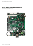
GAM 110 - User Manual
GAM 110 - User Manual
Firmware 1.00.37j7
Neokoros IT - Biometric Technology
ATTENTION! STATIC ELECTRICITY SENSITIVE DEVICE!
The GAM 110 just like any other electronic device is susceptible to irreparable
damage caused by occasional static electricity discharge in its inner board
and components. It is essential to carry out the static electricity unloading
from the body prior any installation/operation procedures. It is strongly
recommended to avoid any unnecessary contact with the device internal
components. WARNING: damages caused by static electrical discharges are
NOT covered by the End User Warranty Certificate!
To discharge static electricity, consider the following procedures before any
operation including the GAM 110:
1 - With your computer off, make sure it is grounded keeping its power cord plugged into a 3 prong grounded outlet.
2 - Touch - for few seconds - a bare metal frame (not a painted or coated surface) of the computer case.
Turn the computer on.
3 - With the computer on, repeat the step 2. Keep your hand in contact with the computer case for few
seconds.
4 - Consider to use a static eletricity discharging wristband to perform long operations using the GAM 110
internal components. Electricity discharging wristbands are available in electronics supplies stores. Please
refer to manufactures instructions to static electricity discharging optimization.
5 - The device now is ready for assembling and connections. Avoid unnecessary contact with the device
internal components.
ATTENTION!
AVOID INAPPROPRIATE DISPOSAL OF THIS DEVICE AND ITS COMPONENTS!
This device is made using electronic components which can be harmful to environment if not properly disposed. Please check your local rules and regulations for the proper disposal and recycling of this device and its components
after the end of its life cycle.
ATTENTION!
DO NOT USE CAPACITORS FOR RECIRCULATION! USE ONLY DIODE!
IMPORTANT:
TO AVOID DAMAGE TO THE UNIT USE THE PROVIDED SCREWS ONLY.
Additional information covering device installation can be found in the GAM
110 Installation Manual. Before any attempt to install and use GAM 110, please read both documents to assure correct device installation, configuration and
operation.
The internal board connectors shown in this document figures are referring to REV1 of GAM 110.
Connectors in REV or 2 are in different position on the board although they keep the same functions.
GAM 110 - User Manual
Contents
1 - Introduction. ........................................................................................................................................ 9
1.1 - Overview, Features & External Components.................................................................................... 9
1.1.1 - Display Properties.....................................................................................................................10
1.1.2 - Reader/Sensor Properties.........................................................................................................10
1.1.3 - USB Port....................................................................................................................................10
1.1.4 - Keypad Properties....................................................................................................................10
1.1.5 - Menu Navigation Keys/Led Properties.....................................................................................10
1.2 - Hardware Description......................................................................................................................10
1.2.1 - GAM 110 Technical Specifications............................................................................................11
1.2.2 - Unit Dimensions.......................................................................................................................11
2 - Connectors (Rev1). ............................................................................................................................13
2.1 - CN4 - USB Device Port (to computer connection)...........................................................................13
2.2 - CN6 - USB Device Port (to external devices connection).................................................................13
2.3 - CN8 - External Devices & Serial Communication.............................................................................14
2.4 - CN13 - Power Supply & Relays Connector.......................................................................................15
2.5 - BT1 - Battery Socket........................................................................................................................15
2.6 - CN9 - External Keyboard..................................................................................................................16
2.7 - CN10 - External LEDs.......................................................................................................................17
2.8 - CN11 - RFID Antenna (For GAM 110 internal reader only)..............................................................17
2.9 - CN12 - Loudspeaker........................................................................................................................18
2.10 - CN2 - CMOS Image Scanner..........................................................................................................19
2.11- CN3 - Graphical 128x64 LCD Module.............................................................................................20
3 - Menus...................................................................................................................................................20
3.1 - Main screen.....................................................................................................................................21
3.2 - Password Requirement...................................................................................................................21
3.3 - Main Menu......................................................................................................................................22
3.3.1 - Enroll User................................................................................................................................22
3.3.1.1 - Add fingerprint.....................................................................................................................23
3.3.1.2 - Enter Card............................................................................................................................26
3.3.2 - Edit User...................................................................................................................................26
3.3.3 - Identification Modes.................................................................................................................29
3.3.4 - Delete User...............................................................................................................................31
3.3.5 - Delete All..................................................................................................................................32
3.4 - Configure Menu...............................................................................................................................32
3.4.1 - Language..................................................................................................................................33
3.4.2 - Date/Time.................................................................................................................................33
3.4.3 - Network....................................................................................................................................34
3.5 - Operation Menu..............................................................................................................................36
3.5.1 - Master Passwd.........................................................................................................................36
3.5.2 - Mode........................................................................................................................................37
3.5.2.1 - The Standalone mode............................................................................................................37
3.5.2.2 - The On-line mode..................................................................................................................39
3.5.3 - Device.......................................................................................................................................40
3.5.4 - Interface...................................................................................................................................40
3.6 - Files Menu...................................................................................................................................41
4 - NKHM (Neokoros Hardware Manager). ......................................................................................43
4.1 - Identifying GAM 110.......................................................................................................................43
4.2 - Configuration Options “(CA) File”....................................................................................................44
5 - Configuration Options “(CA) File” Parameters........................................................................................46
5.1 - Parameters/Values List....................................................................................................................46
5.1.1 - AcceptKbd.................................................................................................................................46
5.1.2 - AutoGrab..................................................................................................................................47
5.1.3 - BuzzerOff..................................................................................................................................47
5.1.4 - Cafeteria...................................................................................................................................47
5.1.5 - Card..........................................................................................................................................47
5.1.6 - CardS1......................................................................................................................................47
5.1.7 - CardS1BaudRate.......................................................................................................................48
5.1.8 - CardS2......................................................................................................................................48
5.1.9 - CardS2BaudRate.......................................................................................................................48
5.1.10 - Contrast..................................................................................................................................48
5.1.11 - DNSServer...............................................................................................................................48
5.1.12 - Doorsensor.............................................................................................................................49
5.1.13 - FunctionKeys...........................................................................................................................49
5.1.14 - FunctionMenu........................................................................................................................49
5.1.15 - FunctionX ...............................................................................................................................49
5.1.16 - FunctionXPrint........................................................................................................................49
5.1.17 - GIO.........................................................................................................................................50
5.1.18 - Greeting..................................................................................................................................50
5.1.19 - HBInterval...............................................................................................................................50
5.1.20 - HBThreshold...........................................................................................................................51
5.1.21 - HideTyping..............................................................................................................................51
5.1.22 - Language................................................................................................................................51
5.1.23 - MasterPwd.............................................................................................................................51
5.1.24 - MaxOpenDelay.......................................................................................................................51
5.1.25 - MenuTime..............................................................................................................................52
5.1.26 - MIWA......................................................................................................................................52
5.1.27 - Mode......................................................................................................................................52
5.1.28 - Module...................................................................................................................................52
5.1.29 - MonitorUp/MonitorDown......................................................................................................52
5.1.30 - OKTime...................................................................................................................................53
5.1.31 - PortCmd..................................................................................................................................53
5.1.32 - Printer.....................................................................................................................................53
5.1.33 - PushButton.............................................................................................................................53
5.1.34 - RedLEDTime............................................................................................................................54
5.1.35 - Relay.......................................................................................................................................54
5.1.36 - RelayNR..................................................................................................................................54
5.1.37 - RelayTime...............................................................................................................................54
5.1.38 - RelayTimeNR..........................................................................................................................55
5.1.39 - SendEvents (ResubmitRecMa)................................................................................................55
5.1.40 - SendEventsPlain . ...................................................................................................................55
5.1.41 - SendImage..............................................................................................................................56
5.1.42 - SendTemplate.........................................................................................................................56
5.1.43 - ShowCardDecimal..................................................................................................................56
5.1.44 - ShowCardLE............................................................................................................................56
5.1.45 - ShowCardTrunc.......................................................................................................................56
5.1.46 - TimeServer..............................................................................................................................57
5.1.47 - TimeZone................................................................................................................................57
5.1.48 - TurnSensor..............................................................................................................................57
6 - GAM 110/GIO Connection. .............................................................................................................57
7 - GAM 110 Simplified Connector Position and Pin Numbers...................................................60
8 - GAM 110/PLC Equipment Communication. ...............................................................................61
8.1 - GAM 110/PLC Equipment Communication Parameters........................................................ 61
8.1.1 - uDX.Clp0Enabled......................................................................................................................61
8.1.2 - uDX.Clp0Addr...........................................................................................................................61
8.1.3 - uDX.Clp0ComType....................................................................................................................61
8.1.4 - uDX.Clp0TcpMode.....................................................................................................................61
8.1.5 - uDX.Clp0Var..............................................................................................................................61
8.1.6 - uDX.Clp0BaudRate....................................................................................................................61
8.1.7 - uDX.Clp0DataBits.....................................................................................................................62
8.1.8 - uDX.Clp0StopBits......................................................................................................................62
8.1.9 - uDX.Clp0Parity..........................................................................................................................62
8.1.10 - uDX.Clp0FlowCtrl....................................................................................................................62
8.1.11 - uDX.Clp0MyAddr....................................................................................................................62
8.1.12 - uDX.Clp0Ip..............................................................................................................................62
8.1.13 - uDX.Clp0Port..........................................................................................................................62
8.1.14 - uDX.Clp1Enabled....................................................................................................................62
8.1.15 - uDX.Clp1ComType..................................................................................................................63
8.1.16 - uDX.Clp1TcpMode...................................................................................................................63
8.1.17 - uDX.Clp0BaudRate..................................................................................................................63
8.1.18 - uDX.Clp1DataBits...................................................................................................................63
8.1.19 - uDX.Clp1StopBits....................................................................................................................63
8.1.20 - uDX.Clp1Parity........................................................................................................................63
8.1.21 - uDX.Clp1FlowCtrl....................................................................................................................63
8.1.22 - uDX.Clp1Ip..............................................................................................................................64
8.1.23 - uDX.Clp1Port..........................................................................................................................64
ATTENTION!
DO NOT USE CAPACITORS FOR RECIRCULATION! USE ONLY DIODE!
IMPORTANT:
TO AVOID DAMAGE TO THE UNIT USE THE PROVIDED SCREWS ONLY.
1 - Introduction
GAM 110 is a biometric fingerprint reader also equipped with a card reader sensor.
The device uses one of world’s best algorithms in its operational design allowing a fingerprint recognizing
time of about 1 second in Standalone operation mode.
GAM 110 is capable to store up to 12,000 fingerprint samples (templates) with real time information displayed in its LCD screen.
Configuration and data communication uses TCP/IP, RS-232 ports or an USB memory device.
1.1 - Overview, Features & External Components
Following sections covers some of the basic GAM 110 overview, its features and its external components.
- Capable to store up to 2 million events;
- Wiegand output; (to be developed)
- Internal relay designed to support up to 1A (ampère) of electric current;
- POE (Power Over Ethernet);
- Utilization with several different types of RFID cards;
- Equipped with a relay to drive locks, electric locks, electromagnetic locks, (electromagnet), gates, etc.
- Easy installation connectivity and utilization.
Figure 1 shows the arrangement of the components in the external device panel.
Fig. 1: GAM 110 external components
1.1.1 - Display Properties
The LCD graphic display of GAM 110 has 128X64 pixels and two font types: Small (8X6) and Large (16X8).
The display shows menus, screens, data and equipments operation messages.
1.1.2 - Reader/Sensor Properties
The onboard sensor in GAM 110 is a prism based sensor + CMOS image area 15mm X 18mm size, 21mm
(W) X 23mm(L) X 55mm (H) resolution 500DPI. The card reader is capable to operate with several different
RFID card types.
1.1.3 - USB Port
The USB port (fig. 2) is located under the lower area of the GAM 110 keyboard as shown in figure 2. The
port is a host USB port to any USB device connection. Its main purpose is to provide data exporting to a
removable storage device like pen drives and memory keys.
Fig. 2 - GAM 110 USB Port
1.1.4 - Keypad Properties
The keypad in GAM 11 has 12 keys: 0 to 9 numeric keys plus “*” and “#” standard keys. “*” key is used to
cancel operations and return to previous menus. The key “#” is used to select/confirm options and operation modes. Numeric keys can be used to quick access menu options also to enter numeric information
when it is requested; (ex: to type a master password).
1.1.5 - Menu Navigation Keys/Led Properties
Menu navigation keys can be used to select options in the menu, scroll the screen up and down, also to
put the cursor in a specific position in the screen. The LED in the middle of the keys is used for signaling.
Example: if a recognition operation is successful the led will lit with a green color. If the authorization is not
allowed due a non fingerprint recognition (not authorized), a message will be shown in the LCD and the LED
will lit with a red color. A blue color indicates the equipment is in “idle” state.
1.2 - Hardware Description
The following sections describe some of the hardware components used in GAM 110. To detailed installation instructions please refer to GAM 110 Installation Manual document.
10
The unit runs on embedded Linux Operating System, uses an optical scanner (GSO 110) and does not require a PC to run (full Standalone operation mode). However, a PC based program for import/export data
can be used. We strongly recommend NKHM (Neokoros Hardware Management) application to access the
internal configurations of GAM 110 and perform several other actions.
1.2.1 - GAM 110 Technical Specifications
CLASSIFICATION
Power supply
Typical consumption
Processor
Memory
Max number of templates
Display
USB device port
USB host port
External devices
Connectivity
Cardreader
Sensor GSO110
Dimensions
Weight
Verification Type
Recognition Time
Warranty Period
Temperature range
Humidity range
GAM 110 SPEC
External: 12VDC
PoE: PoE: 30VDC - 60VDC - Nominal 48VDC
max 110 mA
ARM9 400MHz
133Mhz 64MB SDRAM and 128MB flash memory
12,000
LDC monochrome 128 x 64 pixels
2 device ports
1 host port
EM, Dead bolt, Strike
TCP/IP
RFID 13,56 Mhz
Prism based sensor + CMOS Image Sensor
170mm(W) x 62mm(L) x 152mm(H)
357 gr.
1:1 / 1:N
< 1.5 second/user
1 year
-20° a 60°
90%
1.2.2 - Unit Dimensions
Fig.3 - GAM 110 unit dimensions - FRONT
11
Fig.4 - GAM 110 unit dimensions - SIDE VIEW (L/R)
12
2 - Connectors (Rev1)
To detailed instructions about how to disassemble the unit panels, please refer to GAM 110 Installation
Manual. The “pin1” in every connector in GAM 110 is indicated by a triangle mark. The “Rev” notation refers to connectors position in the GAM 110 board which can be “Rev1” or “Rev2” according board version. 2.1 - CN4 - USB Device Port (to computer connection)
Fig. 5 - CN4 Connector: USB Device Port
PIN NO
1
2
3
4
5
FUNCTION
vcc
DD+
GND
---
DESCRIPTION
5V Power
DataData+
Ground
Not Used
2.2 - CN6 - USB Device Port (to external devices connection)
Fig. 6 - CN6 Connector: USB Device port to external devices
13
PIN NO
1
2
3
4
5
FUNCTION
vcc
DD+
GND
GND
DESCRIPTION
5V Power
DataData+
Ground
Ground
2.3 - CN8 - External Devices & Serial Communication
Fig. 7 - CN8 Connector: used for connecting external devices and serial communication
PIN NO
1
2
3
4
5
6
7
8
9
10
11
12
13
14
15
16
FUNCTION
IN+
ININ+
INOUT+
OUT+
GND
RS485xA
RS485xB
GND
RX
TX
GND
RX
TX
VCC
DESCRIPTION
Pin 1 Sensor 1
Pin 2 Sensor 1
Pin 1 Sensor 2
Pin 2 Sensor 2
Not implemented
Not implemented
Ground
Not implemented
Not implemented
Serial Ground (Serial 2)
Receive data for serial port, RS-232 level (Serial 2)
Transmit data for Serial port, RS-232 Level (Serial 2)
Serial Ground (Serial 1)
Receive data for serial port, RS-232 level (Serial 1)
Transmit data for Serial port, RS-232 Level (Serial 1)
Positive pin of power supply 12 or 28.8V*
*Value is according the version of GAM 110. A multimeter test in the pin 16 of connector 8 (CN8) is highly recommended. Same
procedure must be executed for CN10 and CN 13 connectors.
14
2.4 - CN13 - Power Supply & Relays Connector
Fig. 8 - CN 13 Connector for power supply and relays
PIN NO
1
2
3
4
5
FUNCTION
IN/OUT Vcc
GND
VCC IN
GND
Relay
DESCRIPTION
12V Auxiliary Power Input/Output
Auxiliary Power Ground
Positive pin of external power supply (12V - 28V)
External Power Ground
Relay Normally Closed (NC)
6
7
Relay
Relay
Relay Common (C)
Relay Normally Open (NO)
2.5 - BT1 - Battery Socket
Fig. 9 - Battery Socket
PIN NO
1
2
FUNCTION
VCC
GND
DESCRIPTION
3V Power
Ground
15
2.6 - CN9 - External Keyboard
Fig.: 10 - The CN9 connector allows the utilization of an external keyboard.
PIN NO
1
2
3
4
5
6
7
8
9
10
16
FUNCTION
Row 2
Row 3
Row 4
Col 1
Col 2
Col 3
Row 1
Col K
Power Switch +
Power Switch -
DESCRIPTION
Row 2 of keyboard
Row 3 of keyboard
Row 4 of keyboard
Column 1 of keyboard
Column 2 of keyboard
Column 3 of keyboard
Row 1 of keyboard
Column K of keyboard
Positive PIN of Switch
Negative PIN of Switch
2.7 - CN10 - External LEDs
Fig. 11 - CN 10 External LEDs connector
PIN NO
1
2
3
4
5
FUNCTION
VCC
LED
LED
LED
GND
DESCRIPTION
12/28V Power Output
Blue Cathode
Red Cathode
Green Cathode
Ground
2.8 - CN11 - RFID Antenna (For GAM 110 internal reader only)
Fig. 12 - CN 11 RFID Antenna connector
17
PIN NO
1
2
3
4
5
6
FUNCTION
Rx
GND
Tx1
GND
Tx2
GND
DESCRIPTION
Receive data for RFID
Ground
Transmit data for RFID (Tx 1)
Ground
Transmit data for RIFD (Tx 2)
Ground
FUNCTION
Out
GND
DESCRIPTION
Audio Out
Ground
2.9 - CN12 - Loudspeaker
Fig. 13 - CN12 loudspeaker connector
PIN NO
1
2
18
2.10 - CN2 - CMOS Image Scanner
Fig. 14 - CN2 Cmos Image Scanner connector
PIN NO
1
2
3
4
5
6
7
8
9
10
11
12
13
14
15
16
17
18
19
20
21
22
FUNCTION
VEL
GND
SD0
SD1
SD2
SD3
SD4
SD5
SD6
SD7
SCL
SDA
RST
NC
HSYNC
GND
MCLK
GND
PCLK
FSYNC
GND
VCC
DESCRIPTION
Vel
Ground
ISI D0
ISI D1
ISI D2
ISI D3
ISI D4
ISI D5
ISI D6
ISI D7
ISI SCL
ISI SDA
ISI RST
ISI FINGER SENS
ISI HSYNC
Ground
ISI MCLK
Ground
ISI PCLK
ISI FSYNC
Ground
3.3 V Power Input
19
2.11 CN3 - Graphical 128x64 LCD Module
Fig. 15 - Graphical LCD Module connector
PIN NO
1
2
3
4
5
6
7
8
9
10
11
12
13
14
15
16
17
18
19
20
FUNCTION
VCC
GND
Vo
D0
D1
D2
D3
D4
D5
D6
D7
CS1
CS2
RST
R/W
D/I
E
Vee
A
K
DESCRIPTION
5V Power Input
Ground
LCD VO
LCDDO
LCD D1
LCD D2
LCD D3
LCD D4
LCD D5
LCD D6
LCD D7
LCD CS1
LCD CS2
LCD RST
LCD R/W
LCD D/I
LCD E
LCD VEE
A
K
3 - Menus
Options, operating modes and all GAM 110 functions are accessible via menus displayed in its LCD screen.
The following sections show how to manage the menus.
20
3.1 - Main screen
The GAM 110 main screen displays the information shown in figure 16.
Fig. 16 - Initial information displayed in GAM 110 LCD main screen
The network communication icon indicates if the unit is able to receive/transmit data. Figures 17 and 18
shows the meaning of each icon status.
Fig. 17 - Network communication
icon indicates there is no connection
Fig. 18 - Network communication icon indicates there is a established connection between
network and GAM 110.
3.2 - Password Requirement
Password request is shown when the [ # ] key is pressed. Type the password and press [ # ] again. To erase
the last digit typed, press [ * ]. After entering the password, press [ # ] to advance to the next menu. If the
password is wrong, a message will be displayed. Default password is 9999. Type it and then press [ # ] to
advance to the next menu; (fig. 19).
Fig. 19 - Type 9999 (master
default password) to access
the next menu.
21
3.3 - Main Menu
GAM 110 main menu (fig. 20) allows the access to four other menus:
Fig. 20 - Navigate using the keys above the keypad and hit the [ # ] to access the desired option. Items can be also selected pressing
the correspondent number in the keypad. The [*] allows to return to the previous screen anytime.*
“1 - User” provides functions related to device users;
“2 - Configure” invoke function items to control GAM 110;
“3 - Operation” provides access to GAM 110 configuration.
“4 - Files” menu contains options to update the device, export data and eject a USB device connected to
the GAM 110 USB port.
To navigate, hit the keys above the keypad and select an item. Press the [ # ] key. The option also can be
directly accessed just pressing it correspondent number.
*NOTE: In this case please assume the normal operational screen, not the password one.
3.3.1 - Enroll User
The “Enroll User” function (Main menu > 1 - User > 1 - Enroll User) presents two constants, two junctions
and three access options.
- “ID”: a constant that returns the local identification number of user;
- “User”: a constant that returns the user code;
- “Identification”: an option to select the type of identification will be applied to user (fingerprint, card,
fingerprint and card...)
- “Type <1-Access>”: function that allows to modify the control type.
- “PIN”: is a function that allows to register the personal identification number of user;
22
- “Add Fingerprint”: option to access fingerprint registration screen;
- “Enter card”: option to access the proximity cards registration screen;
The arrangement of items in the screen is like the figures 21 and 22.
Fig. 21 - “Enroll User” items and options. The additional option in the next section of the screen...
Fig. 22 - allows to apply a user status (normal/admin) and delete data (fingerprints or all user information)
3.3.1.1 - Add fingerprint
Fingerprints acquisition procedure can be executed using the function “Add fingerprint” present in the
“Enroll Usr” menu. Once the option is selected, choose the fingerprint type “<1-Normal>” or “<2-Duress>”
using “<” or “>” keys above the keypad. Then, proceed as follows:
23
1 - Press the [ # ] key. This will invoke the screen shown in figure 23.
Fig. 23 - Starting the fingerprint sample data registration procedure in GAM 110.
2 - Press [ # ] key again. This will select the “Finger: 1 - Right thumb” option.
At this point with the “Finger: 1 - Right thumb” option selected it is possible to choose the finger for fingerprint sample data registration; (fig. 24). To change the finger, press the correspondent number to select:
<1-Right thumb>;
<2-Right index>;
<3-Right middle>;
<4-Right ring>;
<5-Right minimum>;
<6-Left thumb>;
<7-Left index>;
<8-Left middle>;
<9-Left ring>;
<10-Left minimum>.
3 - After the finger selection, press [ # ] key again. This will invoke the fingerprint capture routine. The GAM
110 will ask for the first sample as shown in figure 25.
4 - Put the finger on the reader and wait for the signal. The equipment will ask to repeat the procedure two
more times; (three samples).
5 - After the completion of the capture routine, the equipment will show the following messages:
24
Fig. 24 - With the “Finger” option selected type the correspondent code to change the finger which should be used for the fingerprint sample data registration.
Fig. 25 - Fingerprint capture routine: put the finger in the reader and wait for the audio signal. The equipment will ask to repeat the
procedure two more times
- “Enroll completed”; if all fingerprints were successfully registered;
or
- “Cannot join fingerprints; if errors occurred during the capture routine.
In this case, the GAM 110 will return to “Enroll User” options. Execute the steps again to retry the fingerprint sample data registration.
NOTE: To maximize the efficiency of the capture procedure, please make sure the fingers are clean. Rub
your thumb and finger together to create moisture or oil. This helps the reader read the fingerprint. If your
hands are dry, this may affect the responsiveness of the reader: may cause the reader to not be able to
detect a fingerprint.
25
6 - Repeat the steps for a new user’s fingerprint. The unit automatically will designate the user as a new
one, avoiding a data overwriting on the already registered user.
3.3.1.2 - Enter Card
“Enter Card” function can register a proximity card. When the function is selected, a card can be placed
near the fingerprint reader where is located the internal card reader sensor in the GAM 110.
After positioning the card, its serial number will be displayed in the screen and the unit will require a confirmation of the card registering. Press [ # ] to confirm or [ * ] to cancel. To delete the card, press “0” in the
keypad; (fig. 26).
Fig. 26 - The GAM 110 is equipped with an internal card reader. Card must be placed near the fingerprint sensor area.
3.3.2 - Edit User
The “Edit User” function (Main menu > 1 - User > 2- Edit User) show a screen with an ID request. The first
option “Edit User: Search by”, allows searching users by:
< 1-Global-ID > - Search a user by their global ID;
< 2-Local ID >- Search a user by their local ID;
< 3-PIN > - Search a user by his personal identification number.
The following procedures are examples of how to use the “Edit User” function:
1 - Enter the “Edit User” mode.
2 - In “Search by”, select option 2; “Local ID”.
3 - Press [ # ]. Enter the ID number. In this example, the number used was 0000000000000001, referring to
the first registered user with fingerprints; (fig. 27).
26
Fig. 27 - The “Edit User” function in GAM 110
The same information screen, presented in the “Enroll User” will be invoked, in correspondence to the
designated user, so, it is possible to change its information. In this example, the user designation will be
changed. Please continue with the following steps.
4 - Use the navigation keys above the keypad to select the item “User 1”; referring to user
0000000000000001 found in the “Local ID” mode research in steps 2 and 3; (fig. 28).
Fig. 28 - The “Edit” function allows to change the user designation.
5 - Press [ # ] key. The screen will enter in the editing mode as shown in the fig. 29. In the example, the designation “User 1” will be changed to “John Smith”. Press the following keys:
- 5; (to enter the capital “J”);
- 6 (three times, to enter “o”);
27
Fig. 29 - Using the keypad to enter a user new designation
- 6 (two times, to enter “n”);
- 4 (two times, to enter “h”);
- 0 (to enter a space);
- 7 (four times to enter capital “S”);
- 6 (to enter “m”);
- 4 (three times to enter “i”);
- 8 (one time to enter “t”);
- 4 (two times to enter h).
6 - Press [ # ] to invoke the confirmation screen when it will be possible to confirm and exit, cancel and exit
or clear the entire text to enter a new designation or perform corrections; (fig. 30).
Fig. 30 - Confirmation screen. Use the cursor keys above the keypad to select an option and press [ # } to confirm.
28
Now, the main screen of GAM 110 shows one more information: the number of enrolled users; (fig. 31).
Fig. 31 - The number of enrolled users now is displayed in the main screen of GAM 110.
NOTE: The “Edit User” function also allow to list all enrolled users. Just select the correspondent option in
“Edit User” / “Search by” section.
3.3.3 - Identification Modes
Subject authentication in GAM 110 can be processed by password, fingerprint and id card. Some combinations using more than one authentication can be configured as an authentication mode. The following
identification modes are available in GAM 110:
- Fingerprint + password;
- Card + fingerprint;
- Card + password;
- Card only;
- Fingerprint only;
- PIN + fingerprint;
- PIN + password.
Card, PIN or password can be disabled.
To configure an identification mode using the options available in the “Identification” item, follow this procedure:
29
1 - Type the master password in the unit;
2 - Press “1” to access “USER” menu;
3 - Press “2” to access “EDIT USER” option;
4 - Search and select an user;
5 - Navigate to “IDENTIFICATION” option and press “#”; (fig. 32);
Fig. 32 - Confirmation screen. Use the cursor keys above the keypad to select an option and press [ # } to confirm.
6 - In “Use fingerprint option select one of the following options; (fig. 33);
Fig. 33 - In this section is possible to configure an identification mode.
- 1: Disabled;
- 2: Only fingerprint;
30
- 3: With password;
7 – In “Use card” option select between:
- 1: Disabled;
- 2: Only Card;
- 3: With fingerprint;
- 4: With password;
8 – In “Use PIN” option select between:
- 1: Disabled;
- 2: With password;
- 3: With fingerprint;
9 – Press “*” key till return to the main screen after changes. They will be kept in the device.
3.3.4 - Delete User
The “Delete User” also allows a search for registered samples using “Local ID” and “PIN” search categories.
It is also possible to list all users using the correspondent option. Select the user to be deleted and press
the [ # ]. This will invoke the screen shown in figure 34. Press [ # ] to confirm the deletion or [ * ] to cancel.
WARNING: User deletion operation must be carefully conducted. The deleting action cannot be undone.
Fig. 34 - Delete user confirmation screen
31
3.3.5 - Delete All
The “Delete All” function (1-User > 4- Delete All) allows to remove all registered users from GAM 110 memory. The function will inform the number of enrolled users and the number of fingerprint samples stored
in the device. Enter the informed number (correspondent to the number of enrolled users) and press # to
execute; (figure 35).
Fig. 35 - Deleting operations must be conducted carefully. They can not be undone.
WARNING: User deletion operation must be carefully conducted. The deleting action cannot be undone.
3.4 - Configure Menu
The “Configure” menu allows you to choose the language displayed in GAM 110 LCD, adjust the current
date/time and enter/modify network parameters values. Its options are shown like the figure 36.
Fig. 36 - “Configure” menu options
32
3.4.1 - Language
The Language menu presents a screen with a list of available languages on the equipment. Currently the
GAM 110 available languages are:
1 - English;
2 - Portuguese;
3 - Korean;
4 - Japanese;
5 - Chinese;
6 - Thai.
Select the desired language and press the [ # ] key to confirm; (fig. 37). To return to previous menu press
the [ * ] key.
Fig. 37 - Options of the “Language” menu.
3.4.2 - Date/Time
Adjustments in the current date and time can be made in this section; (2 - Configure > 2 Date/time). Also, is
possible to configure the equipment to operate using daylight saving time.
Type the current date and time and use the arrows/navigation keys (above the keypad) to select AM or PM;
(fig. 38).
Use the arrows/navigation keys pressing the “CLR” key to select “Adjust daylight saving time...” option.
Press [ # ] to invoke the daylight saving time adjustment screen; (fig. 39).
33
Fig. 38 - To adjust the equipment to operate using the daylight saving time, select the correspondent option and press the [ # ] key.
This will...
Fig. 39 - ...invoke the daylight saving time adjustment screen. Enter the values to start and end of daylight saving time period and
set the time difference in “Adjustment”. Confirm the operation pressing the [ # ] key.
Specify the date and time to start/end of the daylight saving time. Insert the time difference in “Adjustment”. Press [ # ] to confirm the deletion or [ * ] to cancel.
3.4.3 - Network
“Network” section allows to configure GAM 110 to operate in the correspondent network when the unit
must be on line and working under a PC computer management and control like NKHM; (Neokoros Hardware Manager).
The section screen is invoked by pressing 2 - Configure > 3 - Network.
34
Figure 40 shows the network parameters to be entered according the PC network configuration. Figure 41
shows the extension of the screen with the option to save and apply all typed parameters values.
Fig. 40 - Network configuration section: enter the corresponding values in the parameters.
Fig. 41 - To save and apply the network configuration select the “Save Settings” option and press [ # ]
To ensure the correct configuration, please follow this procedure:
1 - Connect the unit to the network. Please refer to GAM 110 Installation Manual for connection details.
2 - Open the network configuration values in the computer OS.
3 - Enter the values in the Network section of GAM 110. To avoid hardware conflicts, please notice to not
use values which are already corresponding to other connected devices.
4 - Confirm the values selecting the option shown in figure 41 and pressing the [ # ] key.
5 - Open NKHM software and execute a stress test. Please refer to GAM 110 Installation Manual for details.
35
3.5 - Operation Menu
The “Operation” Menu allows to change the master password, select the GAM 110 operation mode, enable/disable the fingerprint reader, card reader, GIO module and other devices and turn on and off the PIN
characters when it is being typing.
3.5.1 - Master Passwd.
In the following procedures, the default master password will be changed from 9999 (default) to 1234:
1 - From the GAM 110 main screen press the [ # ] key. Enter the default master password value; (9999);
2 - Press 3 key to enter “Operation” menu. Press 1 to access the “Master Passwd.” section; (fig. 42);
Fig. 42 - Setting a new master password
3 - With the “Current password” item selected, type 9999; (factory default value). Press the [ # ] key.
5 - With the “New password” item selected, enter the numbers 1234. Press the [ # ] key.
6 - Select the last item “Confirm password” and type 1234 again. Press the [ # ] key.
7 - A confirmation message will be displayed on the screen; (fig. 43).
Fig. 43 - Password change confirmation screen.
36
GAM 110 master password to access its menus is now 1234.
3.5.2 - Mode
The “Mode” feature allows to configure GAM 110 operation mode which may be:
1 - “On-Line”: for GAM 110 use with a computer running an application for device control and management. Use this operation mode when the GAM 110 is controlled by NKHM (Neokoros Hardware Manager).
2 - ‘Standalone”: When this mode is selected, the whole recognition process including fingerprint readings,
time and attendance, records and etc will be done in GAM 110. The unit will not be controlled by external
devices or applications.
3 - “Fallback”: for GAM 110 use with a computer running an application for device control and management. If a communication or PC hardware failure occurs, the equipment will change its operation mode to
Standalone. The data communication will be up and running when the connection is re-established.
Modes can be selected using the option “Operation mode”; (fig. 44).
Fig. 44 - GAM 110 operation modes.
NOTE: Changes in options of all parameters of the “Mode” menu must be saved. After changing any value,
select “Exit” in the screen extension and press “#”. The “Mode” main screen will be displayed; (pictured
above). Then, select “Save Settings” and press “#” again. If any parameter changing operation is executed
without the applying of the “Save Settings” command, a message will be displayed for value changing confirmation. Press [ # ] for changing confirmation or [ * ] to cancel.
3.5.2.1 - The Standalone mode
Some specific configurations can be applied to “Standalone” mode. Selecting the option “Standalone” and
pressing [ # ] several other options will be displayed; (fig. 45). They are:
37
Fig. 45 - “Standalone” mode options.
- “Push button”: Enable/disable a buttonhole if it is connected to any sensor. The parameters can be
<1-None>;
<2-Sensor 0>;
<3-Sensor 1>;
<4-Sensor 2>;
<5-Sensor 3>;
<6-Sensor 4>.
- “Relay (recognized)”: Specify which relay will be activated when a fingerprint is recognized; (authorization
is OK). Options are:
<1-No Relay>;
<2-Relay 1>;
<3-Relay 2>;
<4-Relay 3>.
- “Relay time (recognized)”: Sets how long the Relay (recognized) will be activated. Time notation is in hundredths of seconds.
- “Relay (not recognized)”: Specify which relay will be activated when a fingerprint is not recognized; (not
authorized). Options are:
<1-No relay>;
38
<2-Relay 1>;
<3-Relay 2>;
<4-Relay 3>.
- “Relay time (not recognized)”: Sets how long the Relay (not recognized) will be activated. Time notation is
in hundredths of seconds.
Settings in “Standalone” mode must be saved to be applied. In the screen extension, select the option
“Exit” and press the [ # ] key. Back to the “Mode” main screen, select “Save Settings” and press the [ # ] key
again.
3.5.2.2 - The On-line mode
Some specific configurations can be applied to “On-line”mode. Selecting the option “On-line” (3-Operation
> 2-Mode >On-line...) and pressing [ # ] several other options will be displayed; (fig. 46).
Fig. 46 - “On line” mode options
They are:
- “Send Images”: Enable/disable. When the “Enable” option is activated, GAM 110 will send the fingerprint
image to computer.
- “Send templates”: Enable/disable. When the “Enable” option is activated, GAM 110 will send the template to computer.
NOTE: A set of specific information is produced when a fingerprint is captured, allowing processing and several other functions. This information set compose a “template”. A “template” refers to digital information
and data produced from a fingerprint image.
- “Heartbeat interval”: Sets the time interval of “heartbeats” packets sent from the GAM 110 to PC in online mode. Values are in hundredths of seconds; (default: 100).
39
- “Heartbeat threshold”: Sets the time limit for “heartbeats” responses after the equipment goes off line
(Standalone mode). Values are in hundredths of seconds; (default: 500).
- “Bits monitor down”: The value is an integer that is interpreted an array of 8 bits. Each bit of the value
enables or disables monitoring corresponding sensor when the sensor goes from 1 to 0 (down). Default: 0.
- “Bits monitor up”: The value is an integer that is interpreted an array of 8 bits. Each bit of the value enables or disables monitoring corresponding sensor when the sensor goes from 0 to 1 (up).
- “Auto-grab video”: When a webcam is connected, its image can be captured and sent to a computer running a compatible application.
Settings in “On-line” mode must be saved to be applied. In the screen extension, select the option “Exit”
and press the [ # ] key. In the main “Mode” screen, select “Save Settings” and press the [ # ] key again.
3.5.3 - Device
The “Device” section; (3-Operation > 3-Device) allows to set up proximity card readers, GIO Module and a
MIWA lock.
Additional configuration for these and other devices can be done using NKHM application in GAM 110 configuration file.
The options in the “Device” section can enable or disable these devices; (fig. 47).
Fig. 47 - In “Device” section, is possible to enable/disable proximity card readers, GIO Module and a MIWA lock
After enabling/disabling, select the option “Save settings” and press [ # ] key to keep and apply any alteration. Changes without saving will display a message to confirm/cancel changes.
3.5.4 - Interface
The “Interface” section; (3-Operation > 4-Interface) allows a PIN typing with options to hide the numbers
inserted by the GAM 110 keypad. The first option enables/disable PIN number entering.
40
The second one enable/disable the PIN typing hiding in LCD. Figure 48 shows the options and their respective parameters.
Fig. 48 - “Interface” section options
After enabling/disabling, select the option “Save settings” and press [ # ] key to keep and apply any alteration.
3.6 - Files Menu
The “Files” menu options refer to data management from an USB device connected to the GAM 110 USB
port. Options are “1-Update”, “2-Export all” and “Eject drive”; (fig. 49).
Fig. 49 - “Files” menu options.
When a USB storage device is connected, the GAM 110 main screen will show a correspondent icon, as it is
shown in figure 50.
41
Fig. 50 - When an USB device is connected, the correspondent icon is displayed in the GAM 110 LCD screen.
A progress bar will be shown indicating the updating process; (fig. 51). The message shown in fig. 52 will be
displayed when the operation is complete. The USB device can be safely removed from GAM 110.
Fig. 51 - Updating operation progress bar.
Pressing any key to return to “Files” menu options. The exporting operation also presents a progress bar.
After the operation is completed, same message shown in figure 52 will displayed.
Fig. 52 - Updating operation completed
ATTENTION! - To preserve data integrity, make sure to remove the USB device only after the confirmation
message. If no option is selected, press the “3” key from the “Files” menu to safely eject the USB device
before remove it.
42
- Never remove the device from the USB port when data transference is in progress from/to USB device.
- Make sure to use an FAT formatted USB device; (IBM-PC file format).
- If the message “USB Flash drive not found” appears on the screen, please remove and reinsert the USB
device in the port.
4 - NKHM (Neokoros Hardware Manager)
Besides its standalone capability, GAM 110 can be controlled by an external management application which
can enable and disable several functions of the equipment when it is used in connection with a PC. These
functions can select between different operation modes and optimize GAM 110 to work with other compatible devices.
The NKHM can access and modify GAM 110 internal “Configuration Attributes”, (CA) a configuration script
file which controls the internal parameters of several attributes related to GAM 110 programming.
The NKHM is presented as an executable file format; (.exe file extension). If it is necessary, please obtain a
copy of the software contacting the Neokoros Authorized Support Service.
4.1 - Identifying GAM 110
The NKHM application can list all connected devices to the network. Once the equipment is recognized,
it can be managed by the application. To additional information related to GAM 110 network recognition
procedures, please refer to equipment Installation Manual.
In the following procedures NKHM will be used to list all devices connected to the network including some
units of the GAM 110 equipment. Please follow the procedures to ensure the correct identification of the
unit when it is connected to the network.
1 - Please refer to GAM 110 Installation Manual for initial procedures to network connection.
2 - From the main screen in GAM 110, press the [ * ] key three times. This will invoke the GAM 110 general
information screen. Please take a note of the highlighted information shown in figure 53.
Fig. 53 - GAM 110 general information screen. Press [ * ] three times.
43
3 - With the unit connected to the network (please refer to the Installation Manual), execute NKHM application.
The NKHM main screen will show a list (fig. 54) of all connected devices.
Fig. 54 - The NKHM will list all compatible biometric devices connected to the network, including all GAM 110 units. If the device is
not present in the list, click “Refresh” button in NKHM. Additional device connection procedures can be found in GAM 110 Installation Manual. The list will show the information matching the GAM 110 screen (serial number/firmware version).
The unit serial number with the firmware version (matching the screen info), indicates the presence of the
GAM 110 unit connected to the network.
4.2 - Configuration Options “(CA) File”
The “Configuration Options”, in the GAM 110 refers to changes in the device configuration file. Changes are
applied under the homonym section where “CA” refers to “Configuration Attributes”.
The options are used to set the GAM 110 and make the unit compatible with the different operation modes
of several other devices.
The GAM 110 contains a factory preset configuration file. Settings are applied by a text script file, read by
NKHM. Specific configuration scripts can be obtained consulting the Neokoros Authorized Support Service.
Some options are automatically configured and applied to the script file when the equipment is in use with
some management applications as Dokeo and others.
To access and change the GAM 110 configuration files, please proceed as it follows:
1 – Make sure the GAM 110 is correctly connected and running in the network band where it must operate.
2 – Run the stress test to confirm if the device data communication link is up; (please refer to GAM 110
Installation Manual).
A successful stress test can be confirmed in the device screen as shown in figure 55.
Fig. 55 - GAM 110 under stress test: a successful test indicates the data communication link between GAM 110 and the network is
up.
44
The “Start” button to run the test now is marked with “Stop”. Click it to cease the test.
3 – Using the NKHM application main screen double click on the GAM 110 indication on the list; (fig. 56).
Fig. 56 - Double click on the identified GAM 110 in the NKHM main screen list
4 – Click on the “Settings” tab. In the “Show” pane, click on “Editor (CA)” button; (fig. 57).
Fig. 57 - In the “Settings” tab options, click on the “Editor (CA)” button.
5 – In the “Configuration file (CA)” pane, click on the “Read” button.
The configuration script will be displayed in the “Hardware tests” screen; (fig. 58).
45
Fig. 58 - Click on “Read” button: the CA file with configuration parameters and their respective values will be shown in NKHM.
6 – Change the parameters values according to the references found in the next section of this manual.
NOTE: Do not change the configuration file without specific parameters and its correct values. It can leave
the GAM 110 unresponsive. Please refer to section 5 before any modification in the configuration file.
7 – In the “Configuration file (CA)” pane, click on the “Save” button.
Changes in the configuration file will be applied in the internal memory of the GAM 110 device.
8 - Close the NKHM application.
5 - Configuration Options “(CA) File” Parameters
Options in GAM 110 can be defined by the parameter values in the CA File. Once the script is displayed in
NKHM screen, the parameters can be inserted with their designated values like a simple text file. Please
notice the syntax of each parameter must be entered correctly.
5.1 - Parameters/Values List
The parameters and its values must be inserted/modified in correspondence with the following list:
5.1.1 - AcceptKbd
Allows typing a user PIN on the keyboard.
46
AcceptKbd=0 (default, disabled)
AcceptKbd=1 (enabled)
5.1.2 - AutoGrab
When a camera is connected to GAM 110 sends a video image when a fingerprint is captured.
AutoGrab=0 (default, disabled)
AutoGrab=1 (enabled)
5.1.3 - BuzzerOff
Enables/disable internal GAM 110 buzzer sound.
BuzzerOff=1 (disable buzzer)
BuzzerOff=0 (enable buzzer)
5.1.4 - Cafeteria
Enable cafeteria validation mode (for cafeteria/mess hall/refectory etc.) - in this mode, besides verifying
access times, the user must have credits in the “CR” file for the specific period (corresponding to a meal
time), otherwise the “No credits” message is displayed.
5.1.5 - Card
Enables/Disable GAM 110 internal card reader.
Card=0 (default, disabled)
Card=4 (proximity card reader enabled)
5.1.6 - CardS1
Enables an additional card reader which should be connected to the serial port 1 (see connector CN8)
CardS1=X
-> (where “X” is the value which should match the connected card reader code)
0-None (default)
1-Mifare SRT Neokoros
2-RFID 125 Khz (any with protocol like Acura’s)
3-Bar Code
8-Mifare Duali DE-ABM6
9-Acu Mifare AM-11
12-Acu Mifare AM-08 (reads serial number only)
47
5.1.7 - CardS1BaudRate
Sets the communication speed to use with CardS1
CardS1BaudRate=X
-> (where “X” is the value of the speed depending of the card reader type)
0-none (default)
Values: an appropriate baud rate as 9600, 19200, 115200...
5.1.8 - CardS2
Enables an additional card reader which should be connected to the serial port 2 (see connector CN8)
CardS2=X
-> (where “X” is the value which should match the connected card reader code)
0-None (default)
1-Mifare SRT Neokoros
2-RFID 125 Khz (any with protocol like Acura’s)
3-Bar Code
8-Mifare Duali DE-ABM6
9-Acu Mifare AM-11
12-Acu Mifare AM-08 (reads serial number only)
5.1.9 - CardS2BaudRate
Sets the communication speed to use with CardS2
CardS2BaudRate=X
-> (where “X” is the value of the speed depending of the card reader type)
0-none (default)
Values: an appropriate baud rate as 9600, 19200, 115200...
5.1.10 - Contrast
Sets display contrast
Contrast=X
-> (where “X” is a value between 0 and 65535)
5.1.11 - DNSServer
Configure one or more DNS servers, each server1, server2 etc. should be a valid IP address. Space around
the server names or commas is ignored.
DNSServer=server1[,server2[,...]]
NOTE: to use IPs outside of the local network, you must configure a gateway for the equipment
48
5.1.12 - Doorsensor
Identifies a door sensor (or any other sensor). Used with “MaxOpenDelay=10000” parameter; (10000 = 10
seconds.
DoorSensor=X
-> (where “X” is a value for deactivated, sensor 1 ou sensor 2)
-1: deactivated (default)
0: sensor 2
1- sensor 1
5.1.13 - FunctionKeys
The number of function keys to enable
default:0
values: A number from 0 to 9. If it is not zero, function keys are enabled on the keyboard. Offline records
contain a field with the number of the function used (or zero if no function is active).
5.1.14 - FunctionMenu
Enables a menu to select a function right after validating access. No effect if FunctionKeys=0.
If FunctionMenu=0, you can select a function by pressing ‘*’ and then the function digit (1 to 9) - the current selected function name will appear on top of screen. You can deselect the function by pressing ‘*’.
If FunctionMenu=1, the GAM will display a menu asking for the function right after validating access. The
function names displayed in the menu can be configured with FunctionX options.
default: 0
value: 0-disabled, 1-enabled
5.1.15 - FunctionX
Name for the function X where X=1 to 9. No effect if X is greater than FunctionKeys
default: the default name used is “Function X” (X=1 to 9)
value: a text string that is displayed when the function is selected.
5.1.16 - FunctionXPrint
Enables or disables printing cafeteria ticket for the function X. No effect if Cafeteria=0 or X is greater than
FunctionKeys.
49
default: 1
value: 0 - do not print ticket if the selected function is X; 1 - print ticket
5.1.17 - GIO
Enable communication with GIO 110 module. Please refer to section 6 for further information.
Gio=0 (default, disabled)
Gio=1 (enabled)
5.1.18 - Greeting
Shows a custom message in the first line of GAM 110 display main screen.
Greeting=X
-> (where “X” is the message content)
Example:
Greeting= Welcome to Neokoros
The message will be displayed as shown in figure 59.
Fig. 59 - The “Greeting”
parameter allows to insert a
custom message in the first
line of the main screen.
5.1.19 - HBInterval
Sets the time between “heartbeats” responses after which the equipment goes StandAlone if mode=2. Use
the syntax:
HBInterval=X
-> (where “X” must be a value for time in hundredths of seconds. Default = 100).
Value also can be set using hexadecimal notation. Example for 100 (default value): HBinterval=0x0064.
50
5.1.20 - HBThreshold
Sets the time limit for “heartbeats” responses, after which the equipment goes off-line. Use the syntax:
HBThreshold=X
->(where “X” must a value for time in hundredths of seconds. Default = 500).
Value also can be set using hexadecimal notation. Example for 500 (default value): HBinterval=0x01f4
5.1.21 - HideTyping
Enable/disable normal characters in the display when the master password is being typed;
HideTyping=0: (default, normal character display)
HideTyping=1: (asterisks characters display)
5.1.22 - Language
Sets the equipment language
Language=XX
-> (where “XX” must be one of the following codes):
EN=English
BR=Portuguese
KR=Korean
JP=Japanese
ZH=Chinese
TH=Thai
5.1.23 - MasterPwd
Sets the equipment master password
MasterPwd=9999 (default)
5.1.24 - MaxOpenDelay
Specifies the amount of time a door can be open before triggering the buzzer on.
MaxOpenDelay=X
-> (where “X” is a value between 0 and 65535 miliseconds. Default: 10000; 10 seconds)
51
5.1.25 - MenuTime
Sets the time duration the menus will be displayed in the screen if there is no keypad activity.
MenuTime=X
-> where “X” is a value between 0 and 65536, default: 30000 (30 sec.).
5.1.26 - MIWA
This parameter is used to enable or disable a MIWA Lock. Requires GIO110 module for utilization. Setting
will only take effect if the option GIO=1.
Miwa=0 (default); (disables Miwa mode)
Miwa=1 (enable Miwa mode)
5.1.27 - Mode
Sets the equipment operation mode.
Mode=0:
-> StandAlone only: The equipment will operate in standalone mode, using an internal database
stored in its memory.
Mode=1:
-> On line only. The device will work connected directly to a computer and send fingerprint images/
templates or keyboard/card events to that computer.
Mode=2:
-> Fallback (default): The device will work connected to a computer, but if the computer stops responding, it will work in standalone mode.
5.1.28 - Module
The “module” parameter allows to enable or disable device biometric reading. Use it to activate or deactivate the fingerprint reader.
Module=1 (enables biometric reading - default).
Module=0 (disables biometric reading).
5.1.29 - MonitorUp/MonitorDown
These parameters are used to monitor the sensor state. Any change of the state is registered and sent to
the server. For on line use only.
MonitorUp=X
-> where “X” is a value correspondent to a sensor
MonitorDown=X
-> where “X” is a value correspondent to a sensor
52
X is an integer value that is interpreted in a range of 8 bits. Each bit of the value on or off corresponds to
monitoring the corresponding sensor.
Sensors 0 and 1 are internal BCGMG sensors. Sensors 2, 3, 4 and 5 are GIO ones.
In binary, each sensor means one bit and the zero sensor is the less significant.
Example:
To monitor sensors 5 and 0, the “X” value is 33 that is equivalent to the 100001 binary value.
5.1.30 - OKTime
Time to display a validation success message such as “Access OK”. If this time is less than RelayTime, the
message stays on screen until RelayTime is elapsed. Otherwise, even after RelayTime is elapsed, the message stays on.
default: 300 = 3 seconds
value: must be a number between 60000 hundredths of seconds.
5.1.31 - PortCmd
Change the default command port. Default: 5546 UDP. This parameter is very useful when several equipments are installed in a web based application and they must be routed thru the network.
PortCmd=X
-> where “X” is a value correspondent to a port.
5.1.32 - Printer
Enables a printer connected to serial 1 to print tickets, mostly used in Cafeteria mode. Do NOT use a printer
together with CardS1 not zero.
default: 0
value: 0-disabled, 1-enabled
5.1.33 - PushButton
When a value is applied, the correspondent sensor is monitored and treats it like a pushbutton to activate
the relay (for example, to opening doors and gates). Syntax for the parameter is:
Pushbutton=X
->(where “X” must a value for the desired sensor):
-1 (default - no monitoring)
0-internal sensor
1-internal sensor
2-GIO relay (GIO connection required)
3-GIO relay (GIO connection required)
4-GIO relay (GIO connection required)
53
5-GIO relay (GIO connection required)
NOTE: Necessary Mode=1(standalone) configuration. Please refer to item 3.5.2 - Mode.
5.1.34 - RedLEDTime
Time to display an error message such as “Not recognized”.
default: 300 = 3 seconds
value: must be a number between 0 to 60000 hundredths of seconds.
5.1.35 - Relay
Specifies which relay will be activated when a fingerprint or card/PIN is recognized. Values may be 0,5,6 and
7. Default: 5 (internal GAM 110 relay). If value=0, no activation. Values 6 and 7 requires a GIO board connection.
Relay=X
-> (where “X” is the value which corresponds to the desired relay):
0=No activation
5=Internal GAM 110 relay
6=Requires a GIO board connection
7=Requires a GIO board connection
5.1.36 - RelayNR
Specifies which relay will be activated when a fingerprint or card/PIN is not recognized. Values may be 0,5,6
and 7. Default: 5 (internal GAM 110 relay). If value=0, no activation. Values 6 and 7 requires a GIO board
connection.
RelayNR=X
-> (where “X” is the value which corresponds to the desired relay):
0=No activation
5=Internal GAM 110 relay
6=Requires a GIO board connection
7=Requires a GIO board connection
5.1.37 - RelayTime
Sets the relay activation time in case of recognition using the syntax:
RelayTime = value
-> (where “value” must be a number between 0 to 12000 hundredths of seconds. Default: 50 = 0.5
seconds).
54
External relay activation requires GIO connection.
WARNING: Very high values used for the relay operation can be harmful for some kinds of devices, mainly
electric door locks.
5.1.38 - RelayTimeNR
Sets the relay activation time in case of recognition failure using the syntax:
RelayTime = value
-> (where “value” must be a number between 0 to 12000 hundredths of seconds. Default: 0. If the
value is zero, then the “relaytime” value is used. External relay activation requires GIO connection.
5.1.39 - SendEvents (ResubmitRecMa)
StandAlone operation mode records are automatically sent to server when the connection is reestablished.
SendEvents=0 (records are not sent); (default)
SendEvents = 1 (send records)
5.1.40 - SendEventsPlain
Send event notifications, via UDP, in a plain text format (see below), where IP is the destination IP address,
and port is the destination UDP port (from 0 to 65535).
SendEventsPlain=IP:port
The format of the packets for SendEventsPlain is a plain text string (ASCII), without a terminator:
1,DT=yyyy-mm-ddThh:nn:ss,E=event,U=user-id,LU=local-user-id,F=finger
where:
- 1 is the format identifier (may change in future versions)
- yyyy-mm-ddThh:nn:ss = date and time of the event in ISO 8601 format
- event = event type (0 = not recognized, 1 = access OK, for others see SDK documentation)
- user-id = system user ID (corresponding to an ID from a computer)
- local-user-id = local user ID (most useful for users enrolled locally)
- finger = index of the finger used
New fields may be added in the future, so user should parse and check field names before the “=” sign.
Example:
1,DT=2015-04-04T14:15:54,E=1,U=1,LU=1,F=2
- date: april 4, 2015, at 14h (2h PM), 15:54; event type = access OK; user has system ID 1 and local ID 1;
finger = 2 (right index)
55
5.1.41 - SendImage
Enables sending a fingerprint image for each fingerprint captured in online mode:
SendImage = 0 (disables sending images)
Sendimage = 1 (default); enables sending images.
5.1.42 - SendTemplate
Enables sending a fingerprint template for each fingerprint captured in online mode.
SendTemplate=0 (disables sending templates) (default).
SendTemplate=1 (enables sending templates).
5.1.43 - ShowCardDecimal
If a card UID (“serial number”) has 4 bytes (or ShowCardTrunc=1 and it has more than 4 bytes), displays the
serial number in decimal. For example:
if ShowCardLE=0 instead of 044D641D displays 72180765
if ShowCardLE=1 instead of 1D644D04 displays 493112580
default: 0
value: 0-disabled, 1-enabled
5.1.44 - ShowCardLE
If a card UID (“serial number”) has 4 bytes (or ShowCardTrunc=1 and it has more than 4 bytes), display
these bytes in little-endian order (inverted).
For example, if the card UID has bytes: 04, 4D, 64, 1D (hexadecimal):
if ShowCardLE=0 displays 044D641D
if ShowCardLE=1 displays 1D644D04
default: 0
value: 0-disabled, 1-enabled
5.1.45 - ShowCardTrunc
If a card UID (“serial number”) has more than 4 bytes, consider only 4 bytes for displaying on screen. The
reason for this option is that some old software may handle only MiFARE cards with 4-byte UID. Affects the
display of card serial number when a card is not recognized, or in the “Enter card” screen (see 3.3.1.2).
default: 0
value: 0-disabled, 1-enabled
56
5.1.46 - TimeServer
Configure one or more time servers (NTP). Each server1, server2 etc. should be a valid IP address, or, if DNS
is configured, a valid DNS name. Space around the server names or commas is ignored.
TimeServer=server1[,server2[,...]]
NOTE: to use IPs outside of the local network (or server names that resolve to internet IPs), you must configure a gateway for the equipment.
5.1.47 - TimeZone
Specifies the current time zone, where “+” (default) or “-” specifies more or less than GMT, hh (1 or 2 digits)
is the hour offset, and optionally mm is the minutes.
TimeZone=[+|-]hh[:mm]
Example: TimeZone=+5 for 5 hours ahead of GMT, like Germany.
NOTE: currently there is no automatic DST. If you are in daylight savings time, add hours manually to the
timezone and change this option.
5.1.48 - TurnSensor
When an access is confirmed, GAM keeps the relay on according the duration set in “RelayTime” parameter
by default. When “TurnSensor” is configured fo 0 or 1, the sensor - when it is back to the initial state - also
put the relay in the same condition (initial state) disconsidering the “RelayTime” parameter current set.
“RelayTime” will keep working normally if the time limit is reached.
TurnSensor=X
-> (where “X” is the value of the correspondent sensor):
1 - No activation (default)
0 - Sensor 0
1 - Sensor 1
6 - GAM 110/GIO Connection
The following diagrams (figs. 60 & 61) shows typical physical GAM 110/GIO Module connection.
To enable GIO functions, please refer to item 5.1.16 from the parameters/values list.
Before connecting the units, consider these instructions:
- To enhance security, use separate power for each GAM system and GIO Secure I/O.
- Connect the power to the No.3 and No.4 of CN13 in the GAM system.
- Connect separate power to the Power-IN of GIO Power-GND of it.
- Connect the Nos. 13, 14 and 15 of CN8 in GAM system to the Power-GND, TXT, RXD of the GIO Secure I/O.
57
- Connect the GIO Power (+12V) and the COM1 .
- Connect the GIO NC1 to the Power of the Lock (+12V).
- Connect the Exit buttons to each of the GIO IN1+, IN1- Connect the Lock GND and the Power-GND.
Fig. 60
58
Fig. 61
59
7 - GAM 110 Simplified Connector Position and Pin Numbers
Fig. 62
60
8 - GAM 110/PLC Equipment Communication
The following sections are a list of parameters used to allow the communication between GAM 110 with
PLC devices. For additional information, please refer to device documentation.
8.1 - GAM 110/PLC Equipment Communication Parameters
Parameters and its values must be inserted using the CA file readable/writable using NKHM application.
8.1.1 - uDX.Clp0Enabled
Enable/disable communication with Dexter uDX200 PLC.
uDX.Clp0Enabled=0: (default) Disable communication.
uDX.Clp0Enabled=1: Enable communication.
8.1.2 - uDX.Clp0Addr
Set the address of the network Master RS-485 DXNET.
8.1.3 - uDX.Clp0ComType
Set the type of communication TCP/IP, RS-232 or RS-485.
uDX.Clp0ComType=0: Sets communication such as TCP/IP.
uDX.Clp0ComType=1: Sets communication such as RS-232.
uDX.Clp0ComType=2: Sets communication such as RS-485.
8.1.4 - uDX.Clp0TcpMode
Sets the mode of communication TCP/IP Client or Server
uDX.Clp0TcpMode = 0: Sets the equipment GAM110 as Client.
uDX.Clp0TcpMode = 1: Sets the equipment GAM110 as Server.
8.1.5 - uDX.Clp0Var
Set the access variable in the PLC, which will receive the ID of the person and the ID of the finger, so that it
is recognized in the equipment GAM110.
8.1.6 - uDX.Clp0BaudRate
Set the baud rate for RS-232 or RS-485.
uDX.Clp0BaudRate = (110, 300, 1200, 2400, 4800, 9600, 19200, 38400, 57600, 115200, 230400, 460800,
921600).
uDX.Clp0BaudRate = 38400 (default).
61
8.1.7 - uDX.Clp0DataBits
Set the data bits for RS-232 or RS-485.
uDX.Clp0DataBits = (5, 6, 7, 8).
uDX.Clp0DataBits = 8 (default).
8.1.8 - uDX.Clp0StopBits
Set the stop bits for RS-232 or RS-485.
uDX.Clp0StopBits = (0, 1).
uDX.Clp0StopBits = 1 (default).
8.1.9 - uDX.Clp0Parity
Set the parity for RS-232 or RS-485.
uDX.Clp0Parity = (0=even, 1=Odd, 2=none)
uDX.Clp0Parity = 2 (default).
8.1.10 - uDX.Clp0FlowCtrl
Set the flow control for RS-232 or RS-485.
uDX.Clp0FlowCtrl = (0=rts/cts, 1=XON/XOFF, 2=none)
uDX.Clp0FlowCtrl = 2 (default).
8.1.11 - uDX.Clp0MyAddr
Set the address of the network equipment GAM110 on RS-485 DXNET.
8.1.12 - uDX.Clp0Ip
Set the IP address of the PLC.
8.1.13 - uDX.Clp0Port
Set the communication port for the equipment that will be configured as a server.
8.1.14 - uDX.Clp1Enabled
Enable/disable communication with Control4 PLC.
uDX.Clp0Enabled=0: (default) Disable communication.
uDX.Clp0Enabled=1: Enable communication.
62
8.1.15 - uDX.Clp1ComType
Set the type of communication TCP/IP or RS-232.
uDX.Clp0ComType = 0: Sets the communication as TCP / IP.
uDX.Clp0ComType = 1: Sets the communication as RS-232.
8.1.16 - uDX.Clp1TcpMode
Sets the mode of communication TCP/IP Client or Server
uDX.Clp0TcpMode = 0: Sets the equipment GAM110 as Client.
uDX.Clp0TcpMode = 1: Sets the equipment GAM110 as Server.
8.1.17 - uDX.Clp0BaudRate
Set the baud rate for RS-232 or RS-485.
uDX.Clp0BaudRate = (110, 300, 1200, 2400, 4800, 9600, 19200, 38400, 57600, 115200, 230400, 460800,
921600).
uDX.Clp0BaudRate = 38400 (default).
8.1.18 - uDX.Clp1DataBits
Set the data bits for RS-232 or RS-485.
uDX.Clp0DataBits = (5, 6, 7, 8)
uDX.Clp0DataBits = 8 (default).
8.1.19 - uDX.Clp1StopBits
Set the stop bits for RS-232 or RS-485.
uDX.Clp0StopBits = (0, 1).
uDX.Clp0StopBits = 1 (default)
8.1.20 - uDX.Clp1Parity
Set the parity for RS-232 or RS-485.
uDX.Clp0Parity = (0=even, 1=Odd, 2=none)
uDX.Clp0Parity = 2 (default)
8.1.21 - uDX.Clp1FlowCtrl
Set the flow control for RS-232 and RS-485.
uDX.Clp0FlowCtrl = (0=rts/cts, 1=XON/XOFF, 2=none)
uDX.Clp0FlowCtrl = 2 (default)
63
8.1.22 - uDX.Clp1Ip
Set the IP address of the PLC.
8.1.23 - uDX.Clp1Port
Set the communication port for the equipment that will be configured as a server.
64
End User Limited Warranty Certificate
NEOKOROS IT uses the latest technology in the production of all the components used for the assembly and
operation of their equipment, ensuring its products against manufacturing defects. This warranty covers
defects in workmanship for a one (1) year period to the end customer since the installation of the related
product and any related component is performed by authorized NEOKOROS IT personnel. This Warranty
Certificate will be valid when presented with the invoice and the product/equipment serial number. In case
of any defect – properly diagnosed and confirmed by the NEOKOROS Authorized Customer Support Service
– replacement of any parts, components and/or accessories required for the perfect equipment function
performance will be provided without any cost to the end customer.
WARRANTY CANCELLATION
This Warranty Certificate will be canceled if the defect is consequent of the following situations:
- Operation in violation of the specified conditions described in the product instruction manuals or in violation of any specified condition explained by the NEOKOROS technical staff;
- Misuse, accident, fall or use of the product in conjunction with any other equipment not previously approved, recognized and/or authorized by NEOKOROS IT;
- Inadequate transport and storage of the product and its components, including its assembling units and
accessories, unauthorized modification, execution of procedures which denote any reverse engineering attempt, maintenance services performed by unauthorized personnel;
- Lightning, power surges, fluctuations in the power grid, damages caused by bad weather conditions,
flooding or any other natural phenomena;
- Violation/removal of the product/equipment Warranty Seal.
HANDLING AND SHIPPING
Expenses due displacement of technicians, transportation of parts, components, handling and insurance
covering are the responsibility of the end customer.
Product/Model Description:
Product Serial Number:
65
Neokoros IT Ltd. – Biometric Technology.
All Rights Reserved: © 2010 – 2015.
No part of this document may be reproduced without the prior permission of Neokoros IT.
Specifications subject to change without notice.
66