1
4ms Pingable Envelope Generator
Eurorack Module User Manual v2015-06-15
Firmware v4.3 / PCB v2.0
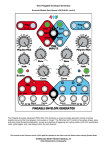
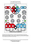
The Pingable Envelope Generator (PEG) from 4ms Company is a dual envelope generator whose envelope
lengths are set by the time between clock pulses or “pings”. The PEG has full CV control of envelope shape, skew,
and ping (clock) division/multiplication, as well as a plethora of triggering and cycling options (AD, AR, quantization,
cycle, cycle toggle), and a tap tempo button for each channel.
DOWNLOAD MOST RECENT MANUAL AT:
http://4mspedals.com/peg.php
Features
•
•
•
•
•
•
Basics:
• Dual “pingable” envelope generator – total envelope time is set by time between pulses ("ping")
• Tap tempo button or external clock/triggers sets the ping time
• Two taps sets the tempo. If a third tap is given close to the tempo to the first two taps, the two timing periods
will be averaged
• Envelope time is a multiple or division of the ping clock (from /8 to x8) set by Ping Div/Mult knob and CV
• Curve knob and CV control the shape of the output envelope. Various combinations of exponential, linear,
logarithmic, and interpolated curves, separately for rise and fall portions
• Skew knob and CV control the ratio between rise and fall times without changing total envelope time.
• Fastest rise time=10µs, fastest fall time=100µs. Slowest rise/fall time=15 min (30 min total)
• Envelope is triggered by Quantized trigger jack, Asynchronous trigger jack, and/or Cycle mode
Outputs and scaling/shifting:
• Scale knob is an attenuating inverter for main envelope output
• Maximum 0V to +10V non-inverted
• Minimum -10V to 0V inverted
• Bi-polar button centers main envelope output around 0V (-5V to +5V output)
• “+5V ENV” jack is a non-scaling output that always produces a 0V to +5V envelope
• “OR” jack outputs an analog OR mix of the two channels' scaled envelope curves
Gate/Trigger outputs:
• End-of-Rise (EOR) gate output goes high when envelope finishes a rise portion, and goes low when envelope
begins a rise portion. Optional trigger mode
• End-of-Fall (EOF) gate output goes high when envelope finishes a fall portion, and goes low when envelope
begins a fall portion. Optional trigger mode
• Half-R (Half-Rise) gate outputs 90-degree phase shifted gates that go high when 50% of the time of the rise
portion has elapsed, and goes low after 50% of the time of the fall portion (this is different than a voltage
comparator-based design). Optional trigger mode
• Tap Clock Output: (enabled in System Edit Mode) dedicated Tap Tempo clock output (gate or trigger)
Triggering/cycling:
• Cycle button for each channel makes envelope self-cycle (LFO mode). Button lights up when on
• “T” jack toggles the state of both channels' Cycle buttons while a gate is applied
• “QNT” jack for each channel triggers an envelope to start at the next quantized beat, with respect to the
divided/multiplied ping clock. Holding a gate high on this jack causes the envelope to repeat.
• “Async” jack for each channel causes an envelope to output immediately (asynchronously). Holding a gate high
results in an AR envelope (rise-sustain-fall). A trigger on Async jack enters Async mode, where the envelope is
no longer phase-locked to the ping clock. A trigger on QNT exits Async mode and enters Sync mode.
CV input jacks:
• CV control of each channel's Ping Div/Mult, Skew, and Curve using the CV jacks.
• Respective knobs set the center offset for the applied CV
• CV of 0-10V will modulate the parameter's full range – however, a 0-5V CV will modulate the parameter within
a useful range.
System Mode:
• Special mode to change advanced parameters
• Re-assign the Half-Rise jack to EOR (and vice-versa)
• Re-assign the EOF jack to Tap Tempo Clock output
• Select Gate or Trigger output from EOR/EOF/Half-R jacks
• Require a continuous external ping clock (unit will not free-run if external ping clock stops)
• Enable/disable skew limiting that keeps fastest rise/fall times at 6ms
Dimensions
•
•
20 HP Eurorack format module
1.6” (40mm) deep
Power consumption
+12V rail:
60mA max with 5V Source jumper selecting external 5V
105mA max with 5V Source jumper selecting internal 5V
+5V rail:
40mA max with 5V Source jumper selecting external 5V
not used with 5V Source jumper selecting internal 5V
-12V rail:
35mA max
Page 2
Your first P.E.G. Patch: a Basic Walkthrough
Step 1: Prepare the PEG
• Unplug all cables from the PEG, turn the Div/Mult, Skew, and Curve knobs to center (12 o'clock), turn Scale all the
way up, and make sure the Cycle and Bi-polar are off (not lit up). Plug the "ENV" jack on the red channel into
something you want to modulate — perhaps a filter, or the pitch of an oscillator.
Step 2: Set your Ping time
Before the PEG can generate an envelope, you need to supply a Ping time. The Ping time is the basic reference that
determines the timing of the envelope.
•
•
Tap the red channel Ping button two or three times, about a second between taps. It's easier to see what's going on
with a slow envelope. The white Ping button should be flashing at the tempo you tapped. If you gave a third tap, the
time between the taps will be averaged (unless the third tap occurs more than 50% different than the timing period of
the first two taps)
You also could run an external clock into the red Ping jack (when a gate is received on the Ping jack, the internal tap
tempo clock is stopped).
Step 3: Provide a trigger source
Like any envelope module, the PEG will produce an envelope when it receives a trigger. Also, like many
envelope modules, it can be set to self-trigger so that it'll cycle without any external trigger.
•
•
Press the red channel Cycle button (it will light up green). Notice the white LED above the
ENV jack starts flashing. The envelope is now running freely, in time with the ping clock.
Adjust the other module(s) you are running the PEG into so you can hear the modulation.
You also could turn Cycle off and run a manual trigger into the QNT or Async jack (e.g. try
the Gate output from a Pressure Points, or perhaps a slow clock output from an RCD/SCM)
Step 4: Adjust your output level
• Adjust the Scale knob and/or play with the Bi-polar button to get a good voltage range that works well
with whatever you're modulating with the PEG.
That's the basic PEG patch: Ping, Trigger, and Output. Now we can play with the parameters of the envelope.
Step 5: Set up your Division/Multiplication amount
• Turn the Ping Div/Mult knob to various settings and watch the Ping button flash faster and slower. Notice
how the tempo doesn't change gradually, but instead jumps from speed to speed. This is because each
speed is an integer multiple or division of the original tempo (e.g. three times as fast, or half as slow). You
also can modulate this parameter with the Div CV jack at the bottom.
Step 6: Adjust Skew and Curve
• Fiddle with the Skew and Curve knobs to get an envelope shape you like. Notice the curve
shapes in the center section of the knob are all symmetrical (same rise and fall shape), while
the shapes at the start and end of the knob's range are asymmetrical (different curves for rise
and fall). Of course, you can modulate these parameters with the CV jacks at the bottom.
Step 7: Play with it! Try triggering the blue channel with the red channel
• Now plug the red EOF (end-of-fall) jack into the blue Ping jack. Turn the blue channel Cycle button On. Run the blue
channel "ENV" jack output to modulate something else. Set Scale and Bi-polar as desired.
Step 8: Modulate the blue channel with the red channel
• Make sure the blue Ping Div/Mult knob is set to "=", and patch the red "+5V ENV" jack into the blue channel's Div CV
jack. Set the red channel Div/Mult knob to something slow. The blue channel should speed up/slow down in time with
the red channel's envelope.
Keep going, play with the "T" jack, try clocking both channels the same and hitting different triggers into the QNT jacks... play
with off-time triggers into the Async jack while the channel is in Cycle mode... modulate each channel with the other, or
themselves... etc etc! Have fun!
Page 3
Ping and Tap Tempo
"Ping" is the core of the PEG: every aspect of the envelope relates back to the timing established by the ping time.
There are two ways to set the ping time:
1. Tap tempo button — tap the white "Ping" button at least twice to set the timing.
◦ It's easiest to tap a tempo with Ping Div/Mult set to "=". This is because the tap tempo clock can be
divided/multiplied just like the external Ping clock. For example, if you tap a tempo with the Ping Div/Mult knob
set to "x4", the Ping light will flash four times as fast as you tapped.
◦ Three taps will average. Two taps set the ping timing period. If you give a third tap, it will be averaged with
the first two taps, unless the timing period set by the third tap is widely different than the first two taps
(specifically, it must be more than half, and less than twice the timing period set by the first two taps).
◦ When a gate is received on the Ping jack, the tap tempo clock is disabled. Try tapping a fast tempo while
you have a slow clock going into the Ping jack — the fast tempo will take effect immediately, but will revert
back to the slow tempo when a gate is received
◦ Hold the Ping button down for 2 seconds to clear the tempo. The light will go off and the envelope will
stop. You also can clear an externally generated ping if the external unit has stopped sending pulses. If you
hold it down for too long, all the lights will flash rapidly and you'll enter System Mode. Don't worry, just release
and hold Ping down again for 2-3 seconds and it will go back to normal mode.
2. External Clock — plug a clock or manual trigger module into the Ping jack.
◦ Only the timing between the last two pulses is used to set the ping clock timing (no averaging). Therefore
you can plug in a manual trigger/gate module and just tap in two pulses: the ping clock will continue to run at
that tempo even though you're not providing any more trigger pulses. Note: in System Mode, you can disable
this free-running feature (thus, giving the PEG two external pulses will output just one envelope and then stop)
See the System Mode section.
◦ The Ping jack has no roll-off, but the main chip can process incoming clocks up to about 10kHz.
However it can only output cleanly up to about 1kHz (depending on your requirements for "cleanly"). So you
can divide an 8kHz clock down to a 1.0kHz triangle wave (/8), moderately cleanly. When outputting frequencies
higher than 1kHz, the output will be noisy and glitchy, but still responsive to the input frequency. Below the
1kHz threshold, the PEG can be used as a rudimentary harmonizer (e.g. sub-octave generator). See Audio
Harmonizer patch.
The maximum time of either envelope curve (rise or fall) is about 15 minutes, total envelope time is 30 minutes.
Ping Divider/Multiplier
Once a ping time has been established, you can then divide or multiply it from 1/8th the speed to 8 times the speed, in whole
number increments. The resulting clock is called the "Divided/Multiplied Ping Clock", or just "Ping Clock" for short.
• The Ping button flashes to the rate of the Divided/Multiplied Ping Clock
• The Ping Div/Mult knob sets the amount of multiplication or division of the incoming ping time, along with any CV that's
applied to the Div jack (the knob sets the offset for the CV)
• Changing the Div/Mult amount in the while an envelope is running will immediately change the slope, and the slope
will continue to track the Div/Mult amount as long as it keeps changing. If no change to the Div/Mult (or skew) is made
after a practically imperceptible duration of time (about 50ms), then the envelope will re-sync to the ping clock based
on the new Div/Mult amount. See Figures 1a and 1b
◦ The except to the re-syncing behavior is that in Async mode, the envelope never re-syncs to the ping clock. See
Async vs. Sync section, and Figure 2.
• Re-syncing transitions are slew-limited to prevent popping when running into a fast-responding VCA
Figure 1a: Changing Div/Mult gradually (slow knob movement)
Slope of envelope tracks the Div/Mult amount until the knob
stops turning (about half-way across the figure), at which point it
re-syncs to the ping clock.
Figure 1b: Changing Div/Mult with a sharp jump from x3 to "="
Notice the envelope didn't touch bottom in order to stay in sync
with the ping clock.
Page 4
Figure 2: Changing Div/Mult in Async mode.
Notice the envelopes do not land on the Ping
clock (envelope is not synced to the ping clock).
Also notice smooth transitions between speeds
Triggering/Cycling the Envelope
•
QNT jack (Quantized) — Apply a trigger/gate to this jack to cause an envelope to start on the next ping clock. The
PEG will wait for the next divided/multiplied ping clock and then start the envelope. Holding a gate high on this jack
causes the envelope to repeat. See Figure 3a. The envelope will complete at least one entire cycle. If a second QNT
pulse is received while the envelope is running, a second envelope will be generated. If the channel is in Async mode,
triggering QNT goes back to sync mode.
◦ Re-phasing with QNT: If Div/Mult is set to /n (dividing), and Cycle button is on, then hitting a trigger into QNT will
re-start (re-phase) the envelope on the next incoming ping clock. This can be useful for multi-phase outputs (e.g.
Quadrature patch). If you want the envelope to run freely without re-phasing, just use one or the other (but not
both QNT and Cycle), or don't divide the ping. See Figures 3b and 3c.
•
Async jack (Asynchronous) — Apply a trigger/gate to this jack to causes the channel to enter Async mode. An
envelope will start immediately. Holding a gate high will cause the envelope to sustain, and then start the fall curve
once the gate is released (A-S-R envelope). In Async mode, the envelope does not sync to the ping clock. However,
the envelope length is still determined by the ping clock. See Async vs. Sync section. See Figure 4, also Figure 2.
•
Cycle Button — Press the button to toggle Cycle mode on/off. When this button is lit up, the envelope will keep
running without needing any external triggers. When the button is turned off, the envelope will finish its cycle, and then
stop when it "hits bottom".
◦ In Sync mode ("normal" mode), turning Cycle on starts outputting an envelope from a point such that the envelope
will end on the next expected ping clock (think of it as if the envelope has always been running in sync to the ping
clock, and turning on Cycle un-mutes it). See Figure 5.
◦ In Async mode, the envelope will start from 0.
•
"T" jack (Cycle Toggle) — When a gate is applied to this jack, both channel's Cycle buttons will toggle state (on->off
and off->on). When the gate is released they will revert to their previous state. The "T" jack is useful for toggling
between the two channels: set one channel in Cycle mode and the other channel to non-cycling, and take the output
from the OR jack (see Outputs section below). The "T" jack is also useful for turning both channels on/off at the same
time.
Figure 3a: Quantized QNT trigger
Applying a QNT trigger causes an envelope to
output at the next ping clock (ping clock not
shown in figure). Holding a gate high causes
the envelope to repeat.
Figure 5: Asynchronous trigger
Trigger causes an envelope to start/re-start
immediately. Holding a high gate causes a
sustain period followed by a fall period when
the gate goes low (ASR envelope)
Page 5
Figure 3b: QNT trigger with
Cycle on and Div/Mult at /4
Bottom trace is ping clock.
On the next ping clock after
applying a QNT trigger, the
envelope resets.
Figure 3c: QNT trigger used to re-phase
Blue channel (top) and Red channel (bottom)
both set to /4, pinged by same clock. Blue is
re-phased twice with QNT trigger. Envelopes
start in-phase, then Blue lags by 90°, then
they are re-phased back together.
Figure 4: Pressing Cycle button in Sync mode
When Cycle is turned on, envelope starts
outputting instantly, from a point in its cycle
such that it's in sync with the divided ping clock.
(Blue trace indicates cycle button ON or OFF)
Skew
Skew is the ratio between the rise and fall times (slopes). Unlike most envelope generators, in the PEG the total envelope
length is held constant when the skew is changed, thus allowing you to change between ramp-up, ramp-down, triangle, and
everything in-between, without altering the timing. See Figure 6.
If Skew is changed while an envelope is running, the curve will update immediately. Some funky outputs can result from this
See Figure 7.
Skew Limiting: Normally the fastest rise time is 10uS, fastest fall time is 200uS. This can sound great into an LPG, LPF, or
modulating all sorts of things, but it's fast enough to cause an audible click into some highly responsive VCAs (such as the
4ms VCA Matrix). Obviously, if you back the Skew knob off from the max/minimum settings the skew will be reduced enough
to avoid popping. However, if you are modulating skew with CV it can require some careful attenuation to prevent popping. A
shortcut solution is built into the PEG's System Mode. When Skew Limiting is enabled, the fastest rise or fall time allowable
will be 6ms, which is slow enough to prevent VCA popping. See the System Mode section for the procedure of how to set the
Skew Limiting parameter (it's the white ENV light).
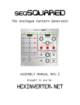
Figure 6: Skew examples. Skew knob was turned up a little bit in between each envelope.
Figure 7: Funky envelopes made by twiddling the skew parameter while envelope is running
Curve
The envelope shapes available in the PEG are formed by combinations of exponential, linear, and logarithmic waveforms. In
between each fully expo/lin/log waveform, there are three interpolated waveforms formed from weighted combinations of
each (e.g. 25% log, 75% linear). The waveforms can be symmetrical (e.g. linear rise & linear fall), or asymmetrical (e.g. exp
rise & log fall). See Figures 8a-8d.
The curve is selected from one of 17 using the Curve knob and CV jack (the knob sets the offset for any applied CV). Look
closely at the artwork around the Curve knob on your PEG to see how the curves are arranged. Asymmetrical curves are at
the extremes, and symmetrical curves are in the center.
As you turn the knob from 0 to max (clockwise), the curves change like this:
• First 4 curves are asymmetrical with exponential attacks and different decays (log->expo) Figure 8a
• Next 4 curves are symmetrical, ranging from exponential to linear in 4 interpolated steps. Figure 8b
• Middle Curve is linear (triangle wave)
• Next 4 curves are symmetrical, ranging from linear to logarithmic in 4 interpolated steps. Figure 8c
• Last 4 curves are asymmetrical with logarithmic attacks and varying decays (log->expo) Figure 8d
Once a rise or fall segment has begun, the shape will not change until the segment ends. However, applying a pulse on the
QNT jack or turning the cycle button on will force an immediate update of the curve shape.
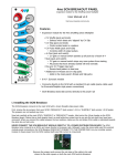
Figure 8a: Curves 1-5
Asymmetrical curves with expo attacks
Figure 8b: Curves 5-9
Symmetrical curves (expo to linear)
Figure 8c: Curves 9-13
Symmetrical curves (linear to log)
Figure 8d: Curves 13-17
Asymmetrical curves with log attacks
Page 6
Envelope Outputs (Main ENV, +5V ENV, OR)
Each side of the PEG has two outputs: a scaled output labeled "ENV" and an unscaled output labeled "+5V ENV".
Additionally, there is a shared output that's the arithmetic "OR" of the scaled outputs.
•
The Scale knob and Bi-polar button only effect the ENV and OR output jacks:
◦ With Bi-polar off: If the scale knob is right of center, the output will be positive-only, from 0V to a maximum of +10V.
Left of center, the envelope inverts and is negative-only, from 0V to a minimum of -10V.
◦ With Bi-polar on: Scale knob right of center, the output will rise from negative to positive, then fall back to negative
voltage (maximum range -5V to +5V). Scale knob left of center, the output starts positive and "rises" to negative
voltage, then "falls" back to positive voltage.
◦ In any setting, Scale knob in the center will produce no output.
◦ The Bi-Polar button is a level-shifter before the scale/inverter. The amount of level-shifting is controlled by a trim
pot on the back of the module. Factory setting is a shift of -5V (thus 0V to +10V becomes -5V to +5V). One
common use would be to set this to about -10V of level shift, so that the output when Scale is inverting would be
positive voltages, but with an inverted waveshape. In this way, the +5V ENV jack and main ENV jacks will produce
inverted copies of the same waveshape, both uni-polar.
•
The main output is the ENV output and its amplitude is controlled by the Scale knob and Bi-polar button
•
The +5V ENV jack always outputs a waveform that goes from 0V to +5V. The scale and bi-polar controls have no
effect on this. This jack is useful as an auxiliary envelope output. It's often useful to patch into the other channel's CV
jack(s) to modulate parameters.
•
The OR jack will output the highest voltage value from either side's ENV jack at any given moment. One way to use
this is to think of the OR jack as a mix out, and use the Scale knobs as level knobs and the Bi-Polar buttons to bring
down the relative level of a channel (kind of like a mute button). See Figure 9c
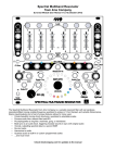
Figure 9a: Changing Scale (Bi-polar off)
Figure 9b: Changing Scale (Bi-polar on)
Top traces are ENV as Scale is turned from max to min. Bottom traces are +5V ENV. Grid lines are 5V/division.
Figure 9c: OR jack vs. adding ENV outputs
Top trace is OR jack (one channel is being
sped up). Bottom trace is from mixing both
channels using a passive mult.
Gate Outputs (EOR/EOF/Half-Rise)
Each channel has two gate outputs: End-of-Fall (EOF), and either End-of-Rise (EOR) or Half-Rise. System Edit Mode can be
used to change the functionality of these jacks, as well as select whether each jack outputs gates or triggers.
•
End-of-Rise outputs a gate that goes high when the fall segment begins, and goes low when the envelope completes.
It is low during a sustain segment. The jack will stay low when the envelope is not running. Another name for this jack
might be "Envelope is Falling". System Mode selects whether it outputs gates or triggers. See Figures 10a and 10b.
•
End-of-Fall outputs a gate that goes high when the fall segment ends and goes low when a rise segment ends. It is
low during a sustain segment. It will stay high when the envelope is not running. Another name for this jack might be
"Envelope is Rising or Resting". System Mode selects whether it outputs gates or triggers. See Figures 11a and 11b.
•
Half-Rise outputs a gate that goes high when 50% of the envelope's rise time has elapsed. It goes low when 50% of
the fall time has elapsed. It is high during a sustain segment, and stays low when the envelope is not running. System
Mode selects whether it outputs gates or triggers. See Figure 12a.
Page 7
•
Skew has a big effect on the EOR/EOF/HR jacks:
◦ Skew changes the pulse width of EOF and EOR in gate mode. Turning Skew to the right (more CV) creates longer
EOR gates and shorter EOF gates. To the left, we get shorter EOR gates and longer EOF gates.
◦ The width of the Half-R gate is always 50% of the envelope time. Changing the Skew will change the phase of the
Half-R output, but not the width. See Figure 12b.
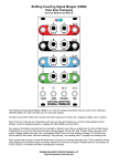
Figure 10a: End-of-Rise (EOR) Gate Figure 11a: End-of-Fall (EOF) Gate
aka "Is Rising or Resting"
aka "Is Falling"
Figure 10b: EOR Trigger output
Width of trigger is 4ms
Figure 12a: Half-Rise Gate
HR goes high 1/2 through time of Rise
(regardless of curve/skew/shape).
Figure 11b: EOF Trigger output
Width of trigger is 4ms
Figure 12b: Phase-shifting Half-R
Blue trace is EOF, Red is Half-R.
Skew knob being turned slowly.
Notice the phase shift from 180 to almost 0
degrees, relative to the rising edges.
Tap Tempo Clock Output
By using System Edit Mode, you can re-assign the EOF jack to output the tap tempo clock (see System Edit Mode section for
the procedure). With this enabled, the EOF jack will always output a free-running clock that you can set by tapping in a
tempo. The jack will always output a steady TTC (Tap Tempo Clock), no matter if the envelope is running or not, and
regardless of the skew, div/mult, or curve settings. In System Mode you can select gate or trigger output.
This is useful for using the PEG as a master clock source.
You can use the Ping button and the EOF jack (which is really TTC) as a separate "module", independent of whatever's
happening with the envelope. That is, the TTC will run steadily no matter how you ping the channel, or set Div/Mult, or
(re-)trigger, Cycle, Skew, etc... The only thing that will change the TTC is physically pressing the Ping button.
One common use for this is to simply patch EOF/TTC into the other channel's Ping jack. Now the channels are synced to your
tap tempo! Or patch the EOF/TTC into a clock divider/multiplier, patching one of the clock outputs back to the same channel's
Ping jack. The remaining clock outputs can be used to keep your other modules in sync with the Tap Tempo clock on the
PEG. You can change the Div/Mult settings on the PEG, or start and stop the PEG's envelope, and your Tap Tempo Clock will
keep running steady.
Async vs. Sync Mode
There are two main modes the PEG runs in: Sync mode and Async mode. The two modes effect the way the envelope is
sync'ed (or not) to the Ping clock. The difference between the modes is easier to see when the Cycle button is on.
How to change between modes:
When the PEG turns on, it starts in Sync mode.
• To enter Sync Mode: Give a trigger/gate into the QNT jack
• To enter Async Mode: Give a trigger/gate into the Async jack
• Tip: If you don't have an external trigger module handy, an quick (and dirty) way to switch modes is to momentarily
plug QNT or Async into any jack that has a light on or flashing (ENV, +5V ENV, EOR, EOF, Half-R)
Differences between modes: (much easier to see with Cycle button on)
• Sync Mode: This is the "normal" PEG mode. The envelope is locked to the Ping clock: it always starts and stops on
the ping clock unless you are rapidly changing Skew or Div/Mult (in which case the PEG will snap back to sync when
about 50ms have passed since any modulation change). See Figures 1a and 1b in the Ping Divider/Multiplier section
•
Page 8
Async Mode: In Async mode, the envelope will try to start on the same point in time relative to the ping clock, but this
point of time (called the "async reset point") can change. With Sync mode, this point in time is the (divided/multiplied)
ping clock itself – but with Async mode, this can be any arbitrary point in time in the ping's cycle. This "async reset
point" can either be set intentionally by hitting a trigger on the Async jack, or it can just "float into place" if you
modulate parameters which change the envelope's landing point. An Async envelope can be 0° to 360° out of phase
with the ping clock, which is useful for phase modulation.
◦ Using Async triggers to change the "async reset point": Try this patch: supply a Ping clock that's about 1 pulse per
second. Use the same clock to make a sound with some other module, using this as a metronome/reference. For
simplicity, turn Div/mult to "=" and Skew to about a sharp rise (maybe 90%). Turn cycle mode on. Hit a trigger into
Async about half a second after a ping. The envelope will restart when it receives the trigger and will continue to
cycle, always starting half a second after each ping. This is your "async reset point": half a second after the ping.
Hit another trigger just a moment before the ping. Now the the envelope will always be starting just a moment
before each metronome pulse. Keep playing with it till it makes sense, this is an advanced but very useful
technique. See Figure 13a
◦ Using skew/div modulations to change the "async reset point": Patch the example above. Try turning Skew back
and forth, as well as Div/Mult. Smooth, huh? Stop turning the knobs and notice how it's now starting at a different
point relative to the metronome. The "reset point" has changed to accommodate your knob wigglings. If you were
in sync mode, it would have snapped back to starting on the ping clock. But in Async mode, it can start anywhere.
See Figure 2 and Figure 13b.
Figure 13a: Async mode (re-triggering)
Envelope starts at the same point on the
ping clock: for the first 3 clocks it's
approximately the falling edge of the
ping. About half-way through the figure,
another async trigger is given and the
reset point becomes a little bit before the
rising edge.
Figure 13b Async mode
(Turning Skew knob in cycle mode)
Since the envelope is not locked to any point
on the ping clock, it may lengthen or shorten
to accommodate the user changing the Skew
parameter.
Beyond Mere Envelopes... Advanced PEG Patching
Hopefully after reading this far into the manual and playing with your PEG, you have a clear understanding of how to make a
variety of timing-dependent envelopes. The following patches illustrate how the PEG's large assortment of inputs and output
types can be used for a variety of purposes besides envelopes.
Clocking both channels with the same clock:
This is a common requirement of many patches. Here's some ideas:
• Mult an external clock and run it into both Pings.
• Enable Tap Tempo Clock Output in System Edit mode and run EOF to the other channel's Ping.
• Run multiple outputs from a clock divider/multiplier, and then mult/divide on the PEG to make them the same tempo
• If your patch doesn't modulate Div/Mult and one channel always will be running, then you can run EOF into the other
channel's Ping.
Complex pattern generator
Use the PEG's quantization features to create complicated repeating beat patterns. It's helpful to have a "metronome" or
"kick" in the background at the steady master clock rate (or slow division of the master clock)
• Run a Shuffling Clock Multiplier x8 output (or RCD /1 out) into Ping. Run another SCM output, say S5 or RCD /3, into
QNT. Cycle Off. Div/Mult to "=". Run the ENV output to open a filter (try a 100% Skew, triangle Curve). If the beat
pattern isn't groovy, use a different clock output into QNT (use the SCM's slip/shuffle!), and adjust Div/Mult.
• To increase complexity, run EOF into the other channel's Ping. Turn that channel's Cycle on or run a different clock
into QNT. Play with Div/Mult. Use the OR out, or run its ENV out to modulate another sound, or perhaps a second
aspect of the same sound. If you can, play with the pulse width of the module feeding QNT jacks (the SCM Breakout
has a PW knob and jack, as do many VCOs and LFOs). Longer PW means more repeated notes.
• Another technique: Patch Tap Tempo Clock output to a clock divider/multiplier module (e.g. SCM). Run a fast output to
PING (e.g. x6). Run a slow output to QNT (e.g. x2). Turn Cycle off. Adjust Div/Mult (e.g."=") and try different outputs
from the clock divider/multiplier module until you get interesting rhythmic patterns.
"Ratcheted" quantized beats
Control the repeat rate of each note in a sequenced bassline.
Clock a sequencer and run the same clock into Ping. Presumably one CV output from the sequencer is controlling the pitch of
your "bassline". Patch a different CV output of the sequencer into Div CV. Turn Cycle on (or run the sequencer's Gate output
into the QNT jack). Set each step to a CV value that corresponds to the number of repeats you want for that particular step.
For example, suppose you have an 8-step sequence and you want notes to be played once for every step until the last note,
which you want to be repeated 8 times and played 8 times as fast... set the sequencer steps 1-7 to 0V output, and step 8 to
5V.
Page 9
If you want to control the number of times the note repeats (e.g. 8 times as fast, but only hit 4 times), you can use a
sequencer with variable pulse width for its gate output (patched into the QNT jack) or another module to change the pulse
width (e.g. Seq Gate->SCM In and SCM x1 -> PEG QNT, playing with SCM's PW knob)
Alternating Skew (or div/mult)
Enable Tap Tempo Clock output. Unplug any external ping. Tap a slow tempo with the Ping button. Turn Skew to 0. Turn
Div/Mult to x8. Turn Cycle on. Patch EOF to Skew CV. You will get four pulses of ramp-up saw followed by four pulses of
ramp-down saw. Try patching into Div CV or Curve CV instead of Skew. Try running EOF through an attenuator before back
into the PEG.
Self-oscillation (self-patched)
Very chaotic interesting noises. Needs a human to fine-tune the settings. Spend some time on this one!
Patch EOF to Ping. Patch ENV output to your audio mixer. Set Div/Mult to between = and x2 (adjust this very slowly
throughout the patch). Cycle On. Scale will be your output volume. Skew and Curve effect the "timbre" (heh). Give PING a
few taps to get it started.
More advanced: Do the basic patch to both channels, with both ENV outputs going to an audio mixer (or just listen to the OR
output). Now patch Half-Rise into the "T" jack. Play with Cycle button settings. Keep patching each channel into itself and/or
the other. Try running one channel's output to control a filter, the other controls a VCO running into the filter.
Video scroll sync
Make sure you are in Sync mode (run a trig->QNT). Use a VCA or logic gate to AND the video Field Sync with a scrolling
audio-rate oscillator. Patch that into PING. You automatically get an LFO that's transposed to the visual scrolling speed of the
pattern (thanks to Lars).
Variation: Run AND'd sync into the QNT trig of the PEG. Then run a different audio-rate oscillator into the PING jack. Cycle
button Off. It will still track the scrolling speed of the first pattern, but the second oscillator controls scrolling within the
scrolling.
Audio Harmonizer
Sub-octave and harmonic series from an audio input
Run an oscillator into Ping input. Cycle On. Set your frequency shift amount with the Div/Mult (e.g. x2 will be an octave up, x3
will be an octave plus a fifth, /8 will be three octaves down, etc...). Audio output from the ENV jack. Scale sets your volume.
Skew and Curve set your waveshape/timbre. Keying Async will mute the signal. Turning Cycle off and keying QNT will gate
the signal.
Do this on both channels and use the T jack to toggle between harmonics, taking the output from the OR jack. Unplug one
channel's Ping to let it slowly drift, creating phaser swooshing sounds.
Run into a LPF with roll-off at 10kHz for a less harsh sound!
Clockable Trigger Delay
A trigger is fed in, and after a delay (which is determined by a clock), a trigger is outputted.
Patch a trigger (e.g. from Pressure Points gate output) to the Async jack. Patch a clock into the PING jack. Set Div/Mult to /2.
Set Skew to center. EOR will be your delayed trigger output (actually is a gate as wide as the clock period ). Changing Skew
will fine-tune the delay time as well as output gate pulse width. To get a true trigger output, enable EOR trigger mode in
System Edit mode.
Keyboard Tempo Tracking
Play a keyboard and the repeat rate of the notes is defined by how fast you hit the keys
Patch a keyboard gate into PING (perhaps use the gate output of a MIDI/CV module, with a MIDI keyboard running in... or a
CV/Gate keyboard, or a Pressure Points. Patch the keyboard CV to a 1V/oct VCO. Run the VCO through a LPG or VCA and
use PEG's ENV out to open the LPG or VCA. Turn Cycle on. Find a nice sounding Skew/Curve combination. The tempo that
you hit the keyboard notes will determine the tempo– hit a key twice and it'll keep repeating at that rate. Play faster and your
repeat rate increases. To keep patching, run another CV (perhaps CC controller CV from the MIDI module, or a second row
on the PP) to control Div/Mult or Skew and Curve.
Phase Shifting
Variable phase shift – two sets of events have variable amount of stagger.
Clock both channels with the same clock (see first example patch idea). Cycle on (both channels). Use both main envelope
outputs to make sound (open two VCAs, perhaps).
Some options for setting the amount of phase difference:
• Manual trigger into Async jack on one channel. For example, to set the blue channel to lag by 25% (90° phase
difference), hit the trigger a quarter of the way after a red channel pulse. Any phase shift amount is possible.
• CV Skew. Changing the skew will change the timing that the peak of the envelope occurs. Thus, sweeping the Skew
of one channel while holding the other steady will cause the envelope peak to shift in phase with respect to the other
envelope's peak. This only a perceptual phase-shift.
• Quantized phase selection. Slow each channel down to /8. Speed your clock up if necessary. Give a trig to both
channel's QNT jacks to make sure you're in Sync mode. Turn blue channel cycle off. Listen to the red channel, and at
a moment just before you want the blue channel to come in, press the blue Cycle button on. The blue channel's phase
will be quantized to one of 8 possible phases (0°, 45°, 90°, 135°, 180°, 225°, 270°, or 315°). It helps to set a sharp
attack on the red channel (Skew at 100%) so you can hear the timing better. Cycle button can be turned off and back
on to change phase again. Use different Div settings for different possible phase shift amounts (e.g. /7 gives 0°, 51°,
102°. etc...)
Quadrature patch
1) First, you have to set up the phase difference between the two channels:
• The easy way: Clock both channels with the same clock (see first example patch idea) and patch the blue channel
Half-R into red channel Async. Turn blue Cycle on and red Cycle off. Adjusting the Skew of the blue channel will
Page 10
change the amount of phase shift from 0-180° (50% skew will be 90°). Note: Half-Rise output should be in trigger
mode or you may get a trapezoidal waveform on Red.
• Another way, just for kicks: Clock both channels together and set both to /4. Give both channels a QNT pulse so
they are in Sync mode. Using the same technique as described in the Quantized phase selection patch above, hit the
Cycle button at the right moment so that one channel is 90 degrees out of phase as the other. Or if you really like
doing things the most complicated way possible, turn blue Skew one mark to the right of center, turn red Cycle off, wait
for red envelope to finish, wait for the blue Half-R LED to go off, and immediately patch blue Half-R into red QNT. The
two channels will be 90 degrees out of phase. Bonus points if you can figure out why! (hint: Skew just right of center
means Half-Rise goes high just before 25%s of the entire envelope has passed...)
2) Now adjust the levels:
• Turn both Scale knobs to about 10:00 (inverting), and both Bi-polar buttons on. Run the main ENV outputs into a Level
Shifter (e.b. Bubblesound LvL+rm or Doepfer A-129/3) to add about 2.5V so that the inverted signals are at the same
DC offset as the +5V ENV outputs. Your four phase shifted outputs will be Blue +5V ENV (0°), Red +5V ENV (90°),
Blue level-shifted ENV (180°), Red level-shifted ENV (270°).
If you use this patch often and want to avoid using an external level shifter module, you can adjust the Bi-Polar trim pot as
described in the Bi-Polar section above.
Jumpers
CLK-BUS jumper:
Install this jumper to enable the PEG
to receive clocks over the Bus (GATE
bus of the standard Doepfer power
rails). This is compatible with the QCD
(version 2.0 and later), as well as the
Makenoise CTRLSEL clock system.
For example, if you have a QCD set to
Lead/Master mode on the same
power bus as the PEG, both channels of the PEG will sync to the QCD. The
PEG's CLK-BUS circuit is fully buffered so you can drive dozens of PEGs (and
other 4ms modules) with one QCD. See QCD v2 manual (page 8).
The Bus Clock can be overridden or disabled on either/both channels of the PEG
by plugging a cable into the Ping jack. Each PEG channel acts independently in
this regard.
Removing the CLK-BUS jumper will ignore all Bus signals. Factory default is
installed.
5V source select jumper (5V SEL):
Jumper on INT: 5V is created from the
12V power rail (factory default)
Jumper on EXT: 5V drawn from 5V
power rail.
LED DIMMER trim pots:
There are 3 trim pots for adjusting the brightness of all the LEDs and LED buttons. All these can be adjusted to your taste.
• LED DIM MAIN controls the brightness of the Cycle, Bi-polar, and Ping buttons (orange and white), as well as the
EOR, EOF, and Half-R LEDs (blue and red). Factory setting: 50% - 75%
• LED DIM ENV1 controls the brightness of the white LED above the red channel's ENV jack. Factory setting: 50%
• LED DIM ENV2 controls the brightness of the white LED above the blue channel's ENV jack. Factory setting: 50%
BP Offset trim pots:
Each channel has a micro trim-pot to adjust the DC offset when Bi-polar is
engaged. The trim-pot is very tiny and can be damaged if turned too far. Do not
adjust it unless you have a specific reason to do so, and be very careful not rotate
it more than 120 degrees from center in either direction (there is no “stop” to
prevent you from turning too far). There is no clear visual line/mark/indicator to
show what position the trim-pot is set, you must use a meter or simply remember
where you've set it. The factory setting is center.
The trimpot has no effect if the Bi-polar button is off. Turning the trim-pot up will add a positive DC offset to the output on
the ENV jack when Bi-polar is turned on. Turning the trimpot down will add a negative DC offset. Always turn the trim-pot in
small amounts (about 5 or 10 degrees at a time), checking to see if the output has shifted the desired amount, and verifying
that it isn't close to the rotational limit.
Page 11
System Mode
System Mode is an advanced feature of the PEG that can be used to re-assign the functionality of jacks, and change
operation in general. It is only present in firmware version 3 and later. Each channel (red/blue) has an independent system
mode, that is, changes made on one channel will have no effect on the other channel.
To enter System Mode:
• Hold the PING button down for 5 seconds (after 2 seconds the tap clock will clear, keep holding it down!)
All the lights except Bi-Polar will flash:
◦ Version 4.1, 4.2 and 4.3: four quick flashes (100ms), then one long flash (500ms)
◦ Version 4.0: four quick flashes (100ms each)
◦ Version 3: five very rapid flashes (50ms each)
• Release the PING button.
• Tap the PING button a few times and notice how one light comes on at a time. This indicates which feature you are
editing. Keep tapping PING to see that you can edit EOR (Half-R on blue channel), EOF, ENV, or PING, or EOR+EOF.
(Note: "ENV" refers to the white LED next to the Bi-Polar button and above the ENV jack
• When a feature is selected, pressing the Cycle button will switch between settings:
OFF = Cycle light off
DIM FLICKER = Cycle light blinking slowly and dimly (not an option for all parameters)
ON = Cycle light on
BRIGHT BLINK = Cycle light blinking quickly and brightly (not an option for all parameters)
•
•
◦ EOR (red) or Half-R (blue): Selects EOR/Half-Rise and Gate/Trigger
▪ OFF: jack will output End-of-Rise Gates (factory setting for Red channel)
▪ DIM FLICKER: jack will output End-of-Rise Triggers
▪ ON: jack will output Half-Rise Gates (factory setting for Blue channel)
▪ BRIGHT BLINK: jack will output Half-Rise Triggers
◦ EOF: Selects EOF/TapClock and Gate/Trigger
▪ OFF: jack will output End-of-Fall Gates (factory setting)
▪ DIM FLICKER: jack will output End-of-Fall triggers
▪ ON: jack will output the Tap Tempo Clock (TTC) Gates. See section on Tap Tempo Clock Output
▪ BRIGHT BLINK: jack will output Tap Tempo Clock (TTC) triggers.
◦ ENV: Selects Skew limiting
▪ OFF: No skew limiting (fastest rise time 10us, fastest fall 200us) (factory setting)
▪ ON: Skew limiting enabled (fastest rise or fall time 10ms) See Skew section in manual
◦ PING: Selects Free Running external ping clock
▪ OFF: Ping clock keeps running regardless of whether the external clock has stopped (factory setting)
▪ ON: Ping clock will stop if the external clock stops. If Tap Tempo Clock is also enabled (gate or trigger), then
the PEG will automatically start using the Tap Tempo Clock
◦ EOF+EOR (both lights on): Select A-S-R or A-R mode for Async jack
▪ OFF: ASR mode (Attack-Sustain-Release). Holding a gate high on the Async jack will cause the envelope to
hold (sustain) until the gate is released
▪ ON: AR mode (Attack-Release). A gate on the Async jack will be ignored, and the envelope will attack and
immediate release (no sustain/hold). The is identical to converting a gate to a trigger before running it into the
Async jack
When you are satisfied with your new settings, press and hold PING for two seconds. All the lights will flash a few
times again. Now you are back to normal operation.
System Mode settings are saved in EEPROM memory, so they will be "remembered" after powering down.
Why would I want to change my system settings?
• Triggers vs. Gates:
Many modules respond differently to gates and triggers. If you are patching EOR/EOF/etc into a standard ADSR
module, you can omit the sustain portion by using triggers. Or, patching from the EOR/EOF jacks into the Async jack,
a gate might give you a sustain portion, but a trigger will avoid that.
• EOF vs. Tap Tempo Clock (TTC):
Usually you will enable this if you want to use the PEG as a master clock. Another reason might be to sync both
channels together.
• Skew Limiting: See also Skew section
You may want to enable this if you are hearing lots of popping when running into a fast-responding VCA and/or
modulating the Skew to its extremes. Note that the exponential and log curves can cause clicking, as they are (by their
nature) fast-changing envelope shapes. These shapes are typically used with a linear VCA, as exponential VCAs
often want to see linear curves. With slower-responding resonant modules (such as a low-pass gate), the expo/log
curves and non-limited skew shapes can be especially delicious....
Firmware Change Log:
PCB Change Log:
v4.3: Made Skew Limiting smoother (less clicking)
v2.0: Added Clock Bus, thinner profile, no
v4.2: Fixed "Clear Ping on Hold" minor bug fixes, widened "x1" snap area
blue select jumper
v4.1: Fixed "Free-running Ping" bug, added Async ASR/AR system mode
v1.0.6 Added LED DIMMER trim pots
v4.0: Fixed glitching envelopes, major bug fixes v1.0.4, v1.03, v1.0.2 Minor assembly changes
v3.0: Added System Modes, tightened timing tracking
Page 12