1
Reference Manual
IQ Programmer
Reference Manual
®
Commands for Bimba Servo and Stepper Drives
Includes RS-232, RS-485,
Ethernet UDP, Ethernet TCP/IP
and EtherNet/IP communication
Contents
Getting Started......................................................................................................................................... 7
Servo Drives.....................................................................................................................................................................7
Stepper Drives..................................................................................................................................................................7
Commands................................................................................................................................................ 8
Buffered Commands........................................................................................................................................................8
Stored Programs in Q Drives............................................................................................................................................8
Multi-tasking in Q Drives...................................................................................................................................................8
Immediate Commands.....................................................................................................................................................8
Using Commands..................................................................................................................................... 8
Commands in Q Drives.....................................................................................................................................................9
SCL Utility Software........................................................................................................................................................10
Command Summary.............................................................................................................................. 11
Motion Commands.........................................................................................................................................................12
Servo Commands..........................................................................................................................................................13
Configuration Commands...............................................................................................................................................13
I/O Commands...............................................................................................................................................................15
Communications Commands.........................................................................................................................................16
Q Program Commands..................................................................................................................................................16
Register Commands.......................................................................................................................................................17
Command Listing................................................................................................................................... 18
AC - Acceleration Rate...................................................................................................................................................19
AD - Analog Deadband...................................................................................................................................................20
AF - Analog Filter............................................................................................................................................................21
AG - Analog Velocity Gain...............................................................................................................................................22
AI - Alarm Reset Input ...................................................................................................................................................23
AL - Alarm Code.............................................................................................................................................................25
AM - Max Acceleration...................................................................................................................................................26
AO - Alarm Output..........................................................................................................................................................27
AP - Analog Position Gain..............................................................................................................................................29
AR - Alarm Reset (Immediate).........................................................................................................................................30
AS - Analog Scaling........................................................................................................................................................31
AT - Analog Threshold....................................................................................................................................................32
AV - Analog Offset Value.................................................................................................................................................33
AX - Alarm Reset (Buffered)............................................................................................................................................34
AZ - Analog Zero............................................................................................................................................................35
BD - Brake Disengage Delay..........................................................................................................................................36
BE - Brake Engage Delay...............................................................................................................................................37
BO - Brake Output.........................................................................................................................................................38
BR - Baud Rate .............................................................................................................................................................40
BS - Buffer Status..........................................................................................................................................................41
CA - Change Acceleration Current..................................................................................................................................42
CC - Change Current.....................................................................................................................................................43
CD - Idle Current Delay Time..........................................................................................................................................45
CE - Communication Error..............................................................................................................................................46
CF - Anti-resonance Filter Frequency..............................................................................................................................47
CG - Anti-resonance Filter Gain......................................................................................................................................48
CI - Change Idle Current.................................................................................................................................................49
CJ - Commence Jogging...............................................................................................................................................50
CM - Command Mode (AKA Control Mode)....................................................................................................................51
CP - Change Peak Current.............................................................................................................................................53
IQ® Programmer Reference Manual
CR - Compare Registers ...............................................................................................................................................54
CS - Change Speed.......................................................................................................................................................55
CT - Continue.................................................................................................................................................................56
DA - Define Address.......................................................................................................................................................57
DC - Change Distance....................................................................................................................................................58
DE - Deceleration...........................................................................................................................................................59
DI - Distance/Position.....................................................................................................................................................60
DL - Define Limits...........................................................................................................................................................61
DR - Data Register for Capture.......................................................................................................................................63
ED - Encoder Direction...................................................................................................................................................64
EF - Encoder Function....................................................................................................................................................65
EG - Electronic Gearing..................................................................................................................................................67
EI - Input Noise Filter......................................................................................................................................................68
EP - Encoder Position....................................................................................................................................................69
ER - Encoder Resolution................................................................................................................................................70
FC - Feed to Length with Speed Change........................................................................................................................71
FD - Feed to Double Sensor...........................................................................................................................................73
FE - Follow Encoder.......................................................................................................................................................74
FI - Filter Input................................................................................................................................................................75
FL - Feed to Length........................................................................................................................................................77
FM - Feed to Sensor with Mask Distance.......................................................................................................................78
FO - Feed to Length and Set Output..............................................................................................................................79
FP - Feed to Position......................................................................................................................................................80
FS - Feed to Sensor.......................................................................................................................................................81
FX - Filter Select Inputs...................................................................................................................................................82
FY - Feed to Sensor with Safety Distance.......................................................................................................................83
GC - Current Command.................................................................................................................................................84
HG - 4th Harmonic Filter Gain.........................................................................................................................................85
HP - 4th Harmonic Filter Phase......................................................................................................................................86
HW - Hand Wheel..........................................................................................................................................................87
Immediate Status Commands........................................................................................................................................88
IA - Immediate Analog....................................................................................................................................................89
IC - Immediate Current (Commanded)............................................................................................................................91
ID - Immediate Distance.................................................................................................................................................92
IE - Immediate Encoder..................................................................................................................................................93
IF - Immediate Format....................................................................................................................................................94
IH - Immediate High Output............................................................................................................................................95
IL - Immediate Low Output.............................................................................................................................................96
IO - Output Status..........................................................................................................................................................97
IP - Immediate Position...................................................................................................................................................98
IQ - Immediate Current (Actual).......................................................................................................................................99
IS - Input Status...........................................................................................................................................................100
IT - Immediate Temperature..........................................................................................................................................103
IU - Immediate Voltage.................................................................................................................................................105
IV - Immediate Velocity.................................................................................................................................................106
IX - Immediate Position Error........................................................................................................................................107
JA - Jog Acceleration...................................................................................................................................................108
JC - Velocity (Oscillator) Mode Second Speed..............................................................................................................109
JD - Jog Disable...........................................................................................................................................................110
JE - Jog Enable............................................................................................................................................................111
3
Contents
JL - Jog Decel..............................................................................................................................................................112
JM - Jog Mode.............................................................................................................................................................113
JS - Jog Speed............................................................................................................................................................114
KC - Overall Servo Filter................................................................................................................................................115
KD - Differential Constant.............................................................................................................................................116
KE - Differential Filter....................................................................................................................................................117
KF - Velocity Feedforward Constant..............................................................................................................................118
KI - Integrator Constant................................................................................................................................................119
KJ - Jerk Filter Frequency.............................................................................................................................................120
KK - Inertia Feedforward Constant................................................................................................................................121
KP - Proportional Constant...........................................................................................................................................122
KV - Velocity Feedback Constant..................................................................................................................................123
LV - Low Voltage Threshold..........................................................................................................................................124
MD - Motor Disable......................................................................................................................................................125
ME - Motor Enable.......................................................................................................................................................126
MN - Model Number.....................................................................................................................................................127
MO - Motion Output.....................................................................................................................................................128
MR - Microstep Resolution...........................................................................................................................................130
MT - Multi-Tasking........................................................................................................................................................131
MV - Model & Revision.................................................................................................................................................132
NO - No Operation.......................................................................................................................................................133
OF - On Fault................................................................................................................................................................134
OI - On Input................................................................................................................................................................135
OP - Option Board.......................................................................................................................................................136
PA - Power-up Acceleration Current.............................................................................................................................137
PB - Power-up Baud Rate ...........................................................................................................................................138
PC - Power-up Current.................................................................................................................................................139
PF - Position Fault........................................................................................................................................................140
PI - Power-up Idle Current............................................................................................................................................141
PL - Position Limit........................................................................................................................................................142
PM - Power-up Mode...................................................................................................................................................143
PP - Power-up Peak Current........................................................................................................................................144
PR - Protocol................................................................................................................................................................145
PS - Pause...................................................................................................................................................................146
PW - Password............................................................................................................................................................147
QC - Queue Call...........................................................................................................................................................148
QD - Queue Delete.......................................................................................................................................................149
QE - Queue Execute.....................................................................................................................................................150
QG - Queue Goto.........................................................................................................................................................151
QJ - Queue Jump.........................................................................................................................................................152
QK - Queue Kill.............................................................................................................................................................153
QL - Queue Load.........................................................................................................................................................154
QR - Queue Repeat......................................................................................................................................................155
QS - Queue Save.........................................................................................................................................................156
QU - Queue Upload......................................................................................................................................................157
QX - Queue Load & Execute.........................................................................................................................................158
RC - Register Counter..................................................................................................................................................159
RD - Register Decrement..............................................................................................................................................161
RE - Restart or Reset...................................................................................................................................................162
RI - Register Increment.................................................................................................................................................163
IQ® Programmer Reference Manual
RL - Register Load - Immediate....................................................................................................................................164
RM - Register Move......................................................................................................................................................165
RR - Register Read......................................................................................................................................................166
RS - Request Status.....................................................................................................................................................167
RU - Register Upload...................................................................................................................................................168
RV - Revision Level.......................................................................................................................................................169
RW - Register Write......................................................................................................................................................170
RX - Register Load - Buffered.......................................................................................................................................171
R+ - Register Add........................................................................................................................................................172
R- - Register Subtract..................................................................................................................................................173
R* - Register Multiply....................................................................................................................................................174
R/ - Register Divide......................................................................................................................................................175
R& - Register AND........................................................................................................................................................176
R| - Register OR...........................................................................................................................................................177
SA - Save Parameters..................................................................................................................................................178
SC - Status Code.........................................................................................................................................................179
SD - Set Direction.........................................................................................................................................................180
SF - Step Filter Frequency............................................................................................................................................181
SH - Seek Home..........................................................................................................................................................182
SI - Enable Input Usage................................................................................................................................................183
SJ - Stop Jogging .......................................................................................................................................................185
SK - Stop & Kill.............................................................................................................................................................186
SM - Stop Move...........................................................................................................................................................187
SO - Set Output...........................................................................................................................................................188
SP - Set Position..........................................................................................................................................................189
SS - Send String..........................................................................................................................................................190
ST - Stop191
TD - Transmit Delay......................................................................................................................................................192
TI - Test Input...............................................................................................................................................................193
TR - Test Register.........................................................................................................................................................194
TS - Time Stamp..........................................................................................................................................................195
VC - Velocity Change....................................................................................................................................................196
VE - Velocity.................................................................................................................................................................197
VI - Velocity Integrator Constant....................................................................................................................................198
VM - Maximum Velocity................................................................................................................................................199
VP - Velocity Mode Proportional Constant....................................................................................................................200
WD - Wait Delay...........................................................................................................................................................201
WI - Wait for Input.........................................................................................................................................................202
WM - Wait on Move......................................................................................................................................................203
WP - Wait Position........................................................................................................................................................204
WT - Wait Time.............................................................................................................................................................205
ZC - Regen Resistor Continuous Wattage....................................................................................................................206
ZR - Regen Resistor Value............................................................................................................................................207
ZT - Regen Resistor Peak Time....................................................................................................................................208
Data Registers...................................................................................................................................... 209
Read-Only Data Registers............................................................................................................................................209
Read/Write Data Registers...........................................................................................................................................209
User-Defined Data Registers.........................................................................................................................................209
Storage Data Registers.................................................................................................................................................209
Using Data Registers........................................................................................................................... 210
5
Contents
Loading (RL, RX)..................................................................................................................................................210
Uploading (RL, RU).......................................................................................................................................................210
Writing Storage Registers (RW) (Q drives only)..............................................................................................................210
Reading Storage Registers (RR) (Q drives only).............................................................................................................211
Moving Data Registers (RM) (Q drives only)...................................................................................................................211
Incrementing/Decrementing (RI, RD) (Q drives only)......................................................................................................211
Counting (RC, “I” register) (Q drives only)......................................................................................................................211
Math and Logic (R+, R-, R*, R/, R&, R|) (Q drives only).................................................................................................211
Conditional Testing (CR, TR) (Q drives only)..................................................................................................................211
Data Register Assignments................................................................................................................. 212
Read-Only Data Registers: a - z...................................................................................................................................212
Read/Write Data Registers: A - Z..................................................................................................................................216
User-Defined Data Registers: 0 - 9, other characters....................................................................................................219
Appendices........................................................................................................................................... 221
Appendix A: Non-Volatile Memory in Q drives...............................................................................................................222
Appendix B: Host Serial Communications....................................................................................................................223
Appendix C: Host Serial Connections...........................................................................................................................227
Appendix D: The PR Command....................................................................................................................................231
Appendix E: Alarm and Status Codes...........................................................................................................................235
Appendix F: Working with Inputs and Outputs..............................................................................................................241
Appendix G: eSCL (SCL over Ethernet) Reference........................................................................................................247
Appendix H: EtherNet/IP..............................................................................................................................................258
Appendix I: Troubleshooting.........................................................................................................................................287
Appendix J: List of Supported Drives............................................................................................................................289
GETTING STARTED
IQ® Programmer Reference Manual
Getting Started
The basic procedures for integrating a Bimba drive into your application are the same for every drive offered. The
first step is to configure and/or tune the drive using either Bimba IQ® Stepper or Bimba IQ® Servo. Depending on
the specific drive, the user may now use SCL Utility or Bimba IQ® Programmer software for testing and advanced
programming.
Servo Drives
•
This series includes all SRV-DC7, SRV-AC3, and SRV-AC5 drives.
•
For Ethernet-enabled drives, see Appendix G of this document and your drive’s Hardware Manual for
information regarding Ethernet communications.
•
Use Bimba IQ® Servo software to tune and configure your drive. See the Bimba IQ® Servo Software Manual
for details on tuning servo drives.
•
For SCL applications choose the SCL Operating Mode; for Q applications choose either the SCL or Q
Program Operating Mode.
•
For SCL applications, the SCLB Setup Utility is a useful tool to gain familiarity with the SCL command syntax
and to test commands that will be used in the final product.
•
For Q applications use Bimba IQ® Servo both for creating stored programs and for sending commands to
your drive.
Stepper Drives
•
This series includes all STP-10, ITM-23Q, and STP-AC5 drives.
•
For Ethernet-enabled drives, see Appendix G of this document and your drive’s Hardware Manual for
information regarding Ethernet communications.
•
Use Bimba IQ® Stepper software to define your motor, configure the operating mode and encoder (if
applicable), as well as any application-specific I/O requirements.
•
For SCL applications choose the SCL Operating Mode; for Q applications choose either the SCL or Q
Program Operating Mode.
•
For SCL applications, the SCL Setup Utility is a useful tool to gain familiarity with the SCL command syntax
and to test commands that will be used in the final product.
•
For Q applications use Bimba IQ® Programmer both for creating stored programs and for sending
commands to your drive.
7
COMMANDS
IQ® Programmer Reference Manual
Commands
There are two types of host commands available: buffered and immediate. Buffered commands are loaded into and executed out
of the drive’s volatile command buffer, also known as the queue. Immediate commands are not buffered: when received by the
drive they are executed immediately.
Buffered Commands
After being loaded into the command buffer of a drive, buffered commands are executed one at a time. (See “Multi-tasking in Q
Drives” below for an exception to this rule). If you send two buffered commands to the drive in succession, like an FL (Feed to
Length) command followed by an SS (Send String) command, the SS command sits in the command buffer and waits to execute
until the FL command is completed. The command buffer can be filled up with commands for sequential execution without the
host controller needing to wait for a specific command to execute before sending the next command. Special buffer commands,
like PS (Pause) and CT (Continue), enable the buffer to be loaded and to pause execution until the desired time.
Stored Programs in Q Drives
Stored Q Programs, created with the Bimba IQ® Programmer application software, are created by using only buffered commands.
Multi-tasking in Q Drives
Multi-tasking allows for an exception to the “one at a time” rule of buffered commands. The multi-tasking feature of a Q drive
allows you to initiate a move command (FL, FP, CJ, FS, etc.) and proceed to execute other commands without waiting for the
move command to finish.
Immediate Commands
Immediate commands are executed right away, running in parallel with a buffered command if necessary. For example, this allows
you to check the remaining space in the buffer using the BS (Buffer Status) command, or the immediate status of digital inputs
using the IS (Input Status) command, while the drive is processing other commands. Immediate commands are designed to
access the drive at any time.
Bimba recommends waiting for an appropriate Ack/Nack response from the drive before sending subsequent commands. This
adds limited overhead but ensures that the drive has received and executed the current command, preventing many common
communication errors. If the Ack/Nack functionality cannot be used in the application for any reason, the user should allow a
10ms delay between commands to allow the drive sufficient time to receive and act on the last command sent.
This approach allows a host controller to get information from the drive at a high rate, most often for checking drive status or
motor position.
Using Commands
The basic structure of a command packet from the host to the drive is always a text string followed by a carriage return (no line
feed required). The text string is always composed of the command itself, followed by any parameters used by the command.
The carriage return denotes the end of transmission to the drive. Here is the basic syntax.
YXXAB<cr>
In the syntax above, “Y” symbolizes the drive’s RS-485 address, and is only required when using RS-485 networking. “XX”
symbolizes the command itself, which is always composed of two capital letters. “A” symbolizes the first of two possible
parameters, and “B” symbolizes the second. Parameters 1 and 2 vary in length, can be letters or numbers, and are often optional.
The “<cr>” symbolizes the carriage return which terminates the command string. How the carriage return is generated in your
application will depend on your host software.
Once a drive receives the <cr> it will determine whether or not it understood the preceding characters as a valid command. If it
did understand the command the drive will either execute or buffer the command. If Ack/Nack is turned on (see PR command),
the drive will also send an Acknowledge character (Ack) back to the host. The Ack for an executed command is % (percent sign),
and for a buffered command is * (asterisk).
8
IQ® Programmer Reference Manual
It is always recommended that the user program wait for an ACK/NACK character before subsequent commands are sent. If the
ACK/NACK functionality cannot be used in the application, a 10ms delay is recommended between non-motion commands.
If the drive did not understand the command it will do nothing. If Ack/Nack is turned on a Nack will be sent, which is signified by
a ? (question mark). The Nack is usually accompanied by a numerical code that indicates a particular error. To see a list of these
errors see the PR command details in the Appendix.
Responses from the drive will be sent with a similar syntax to the associated SCL command.
YXX=A<cr>
In the syntax above, “Y” symbolizes the drive’s RS-485 address, and is only present when using RS-485 networking. “XX”
symbolizes the command itself, which is always composed of two capital letters. “A” symbolizes the requested data, and may
be presented in either Decimal or Hexadecimal format (see the IF command). The “<cr>” symbolizes the carriage return which
terminates the response string.
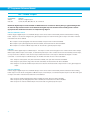
Commands in Q Drives
Q drives have additional functionality because commands can also be composed into a stored program that the Q drive can run
stand-alone. The syntax for commands stored in a Q program is the same as if the commands were being sent directly from the
host, or “XXAB”. Bimba IQ® Servo software is used to create stored Q programs and can be downloaded for free from www.
bimba.com/support/software.php.
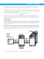
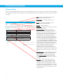
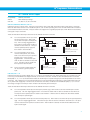
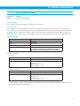
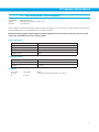
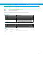
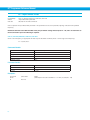
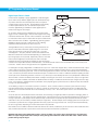
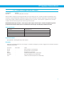
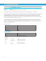
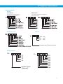
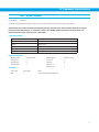
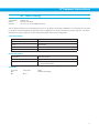
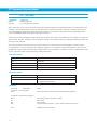
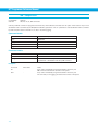
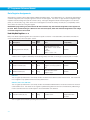
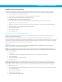
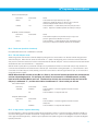
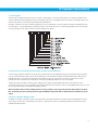
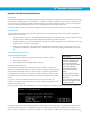
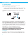
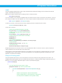
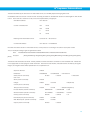
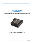
The diagram below shows how commands sent from the host’s serial port interact with the volatile command buffer (AKA the
Queue), and the drive’s non-volatile program memory storage. Loading and Uploading the Queue contents via the serial port are
done with the QL and QU commands, respectively. Similarly, the Queue’s contents can be Loaded from NV memory using the QL
and QX commands, and can be saved to NV memory with the QS command. Finally, commands currently in the Queue can be
executed with the QE or QX command.
RS-232 /
RS-485 /
Ethernet
Communications
Serial /
Ethernet
Port
The Bimba IQ® Programmer software automates many of the functions shown in the diagram above.
9
IQ® Programmer Reference Manual
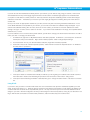
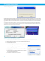
SCL Utility Software
The SCL Utility software is an excellent application for familiarizing yourself with host commands. SCL Utility can be downloaded
for free from www.bimba.com.
To send commands to your drive from SCL Utility simply type a command in the Command Line and press the ENTER key to send
it. (Remember that all commands are capital letters so pressing the Caps Lock key first is a good tip). Pressing the ENTER key
while in SCL Utility does two things: it terminates the command with a carriage return and automatically sends the entire string.
Try the example sequence below. In this example, note that <ENTER> means press the ENTER key on your keyboard, which is
the same as terminating the command with a carriage return.
IMPORTANT: We recommend practicing with SCL commands with no load attached to the motor shaft. You want the
motor shaft to spin freely during startup to avoid damaging mechanical components in your system.
AC25<ENTER>
Set accel rate to 25 rev/sec/sec.
DE25<ENTER>
Set decel rate to 25 rev/sec/sec
VE5<ENTER>
Set velocity to 5 rev/sec
FL20000<ENTER>
Move the motor 20000 steps in the CW direction.
If your motor didn’t move after sending the FL20000 check the LEDs on your drive to see if there is an error present. If so send
the AR command (AR<ENTER>) to clear the alarm. If after clearing the alarm you see a solid green LED it means the drive is
disabled. Enable the drive by sending the ME command (ME<ENTER>) and verify that the you see a steady, flashing green LED.
Then try the above sequence again.
Here is another sample sequence you can try.
JA10<ENTER>
Set jog accel rate to 10 rev/sec/sec
JL10<ENTER>
Set jog decel rate to 10 rev/sec/sec
JS1<ENTER>
Set jog speed to 1 rev/sec
CJ<ENTER>
Commence jogging
CS-1<ENTER>
Change jog speed to 1 rev/sec in CCW direction
SJ<ENTER>
Stop jogging
In the above sequence notice that the motor ramps to the new speed set by CS. This ramp is affected by the JA and JL
commands. Try the same sequence above with different JA, JL, JS, and CS values to see how the motion of the motor shaft is
affected.
10
IQ® Programmer Reference Manual
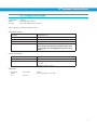
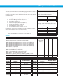
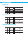
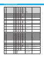
Command Summary
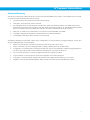
This section contains a set of tables that list all of the Host Commands available with your drive. In each table there are a number
of columns that give information about each command.
•
“Command” shows the command’s two-letter Command Code.
•
“Description” shows the name of each command.
•
“NV” designates which commands are Non-volatile: that is, which commands are saved in non-volatile memory when
the SA (Save) command is sent to the drive. Note that certain commands (PA, PB, PC, PI, and PM) save their parameter
data to non-volatile memory immediately upon execution, and need not be followed by an SA command.
•
“Write only” or “Read only” is checked when a command is not both Read/Write compatible.
•
“Immediate” designates an immediate command (all other commands are buffered).
•
“Compatibility” shows which drives use each of the commands.
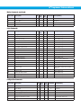
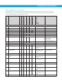
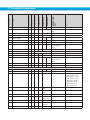
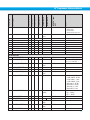
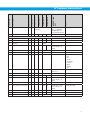
The different categories for these tables - Motion, Servo, Configuration, I/O, Communications, Q Program, Register - are set up to
aid you in finding particular commands quickly.
•
“Motion” commands have to do with the actual shaft rotation of the step or servo motor.
•
“Servo” commands cover servo tuning parameters, enabling / disabling the motor, and filter setup.
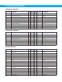
•
“Configuration” commands pertain to setting up the drive and motor for your application, including tuning parameters for
your servo drive, step resolution and anti-resonance parameters for your step motor drive, etc.
•
“I/O” commands are used to control and configure the inputs and outputs of the drive.
•
“Communications” commands have to do with the configuration of the drive’s serial ports.
•
“Q Program” commands deal with programming functions when creating stored programs for your Q drive.
•
“Register” commands deal with data registers. Many of these commands are only compatible with Q drives.
11
IQ® Programmer Reference Manual
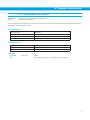
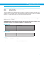
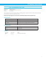
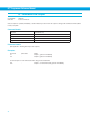
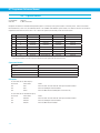
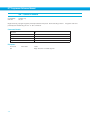
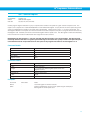
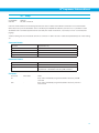
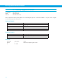
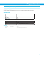
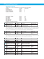
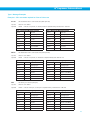
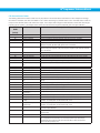
Motion Commands
Command
Description
AC
Accel Rate
•
All drives
AM
Accel Max
•
All drives
CJ
Commence Jogging
DC
Distance for FC, FM, FO, FY
•
All drives
DE
Decel Rate
•
All drives
DI
Distance or Position
•
All drives
ED
Encoder Direction
•
Servos and steppers with encoder
feedback
EF
Encoder Function
•
Servos and steppers with encoder
feedback
EG
Electronic Gearing
•
All drives
EI
Input Noise Filter
•
All drives
EP
Encoder Position
FC
Feed to Length with Speed Change
•
All drives
FD
Feed to Double Sensor
•
All drives
FE
Follow Encoder
•
All drives
FL
Feed to Length
•
All drives
FM
Feed to Sensor with Mask Dist
•
All drives
FO
Feed to Length & Set Output
•
All drives
FP
Feed to Position
•
All drives
FS
Feed to Sensor
•
All drives
FY
Feed to Sensor with Safety Dist
•
All drives
HW
Hand Wheel
•
All drives
JA
Jog Accel/Decel rate
•
All drives
JC
Velocity mode second speed
•
All drives
JD
Jog Disable
•
All drives
JE
Jog Enable
•
All drives
JL
Jog Decel rate
•
All drives
JM
Jog Mode
•
Al drives (see JM command)
JS
Jog Speed
•
All drives
MD
Motor Disable
ME
Motor Enable
MR
Microstep Resolution
•
Stepper drives only
PA
Power-up Accel Current
•
ITM stepper drives only
SD
Set Direction
•
SH
Seek Home
•
SJ
Stop Jogging
•
SM
Stop the Move
•
SP
Set Absolute Position
ST
Stop Motion
VC
Velocity for Speed Change (FC)
12
NV
write
only
read Immediate Compatibility
only
•
All drives
Servos and steppers with encoder
feedback
•
All drives
•
All drives
ITM stepper drives with Flex I/O only
All drives
•
All drives
Q drives only
All drives
•
•
•
All drives
All drives
IQ® Programmer Reference Manual
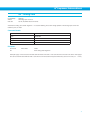
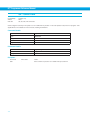
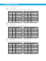
Motion Commands (continued)
Command
Description
NV
write
only
read Immediate Compatibility
only
VE
Velocity Setting (For Feed Commands)
•
All drives
VM
Velocity Max
•
All drives
WM
Wait on Move
•
Q drives only
WP
Wait on Position
•
Q drives only
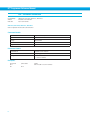
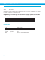
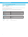
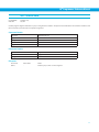
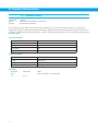
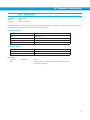
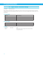
Servo Commands
Command
Description
CP
Change Peak Current
EP
Encoder Position
GC
Current Command
IC
Immediate Current Command
IE
NV
write
only
read Immediate
only
•
Compatibility
Servo drives only
Servo drives only
•
•
Servo drives only
•
•
Servo drives only
Immediate Encoder Position
•
•
Servo drives only
IQ
Immediate Actual Current
•
•
Servo drives only
IX
Immediate Position Error
•
•
Servo drives only
KC
Overall Servo Filter
•
Servo drives only
KD
Differential Constant
•
Servo drives only
KE
Differential Filter
•
Servo drives only
KF
Velocity Feedforward Constant
•
Servo drives only
KI
Integrator Constant
•
Servo drives only
KJ
Jerk Filter Frequency
•
SRV-DC7 Servo drives only
KK
Inertia Feedforward Constant
•
Servo drives only
KP
Proportional Constant
•
Servo drives only
KV
Velocity Feedback Constant
•
Servo drives only
PF
Position Fault
•
Servo drives, drives with encoder
feedback
PL
Position Limit
•
Servo drives only
PP
Power-Up Peak Current
•
Servo drives only
VI
Velocity Integrator Constant
•
Servo drives only
VP
Velocity Mode Proportional Constant
•
Servo drives only
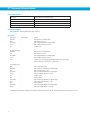
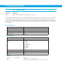
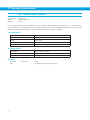
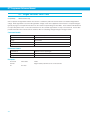
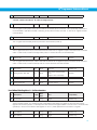
Configuration Commands
Command
Description
NV
write
only
read Immediate
only
AL
Alarm Code
AR
Alarm Reset
BD
Brake Disengage Delay time
•
BE
Brake Engage Delay time
•
BS
Buffer Status
CA
Change Acceleration Current
•
ITM stepper drives only
CC
Change Current
•
All drives
•
•
Compatibility
•
All drives
•
All drives
All drives
All drives
•
•
All drives
13
IQ® Programmer Reference Manual
Configuration Commands (continued)
Command
Description
CD
Idle Current Delay
•
Stepper drives only
CF
Anti-resonance Filter Frequency
•
Stepper drives only
CG
Anti-resonance Filter Gain
•
Stepper drives only
CI
Change Idle Current
•
Stepper drives only
CM
Control mode
•
All drives
CP
Change peak current
•
Servo drives only
DA
Define Address
•
All drives
DL
Define Limits
•
All drives
DR
Data Register for Capture
ED
Encoder Direction
•
Servo drives, drives with encoder
feedback
ER
Encoder or Resolution
•
Servo drives, drives with encoder
feedback
HG
4th Harmonic Filter Gain
•
Stepper drives only
HP
4th Harmonic Filter Phase
•
IA
Immediate Analog
•
•
All drives
ID
immediate Distance
•
•
All drives
IE
Immediate Encoder
•
•
Servo drives, drives with encoder
feedback
IF
Immediate Format
•
All drives
IQ
Immediate Current
•
•
Servo drives only
IP
Immediate Position
•
•
All drives
IT
Immediate Temperature
•
•
All drives
IU
Immediate Voltage
•
•
All drives
IV
Immediate Velocity
•
•
All drives
LV
Low Voltage Threshold
MD
Motor Disable
•
All drives
ME
Motor Enable
•
All drives
MN
Model Number
•
All drives
MO
Motion Output
•
All drives
MR
Microstep Resolution
•
All drives (deprecated - see EG
command)
MV
Model & Revision
OF
On Fault
•
Q drives only
OI
On Input
•
Q drives only
OP
Option Board
•
PA
Power-up Acceleration Current
•
PC
Power up Current
•
All drives
PF
Position Fault
•
Servo drives, drives with encoder
feedback
PI
Power up Idle Current
•
Stepper drives only
PL
In Position Limit
•
Servo drives only
14
NV
write
only
read Immediate
only
•
Compatibility
Q servo drives only
Stepper drives only
•
•
All drives
•
•
•
•
•
All drives except Blu servos
All drives
IQ® Programmer Reference Manual
Configuration Commands (continued)
Command
Description
NV
write
only
read Immediate
only
PM
Power up Mode
•
All drives
PP
Power up peak current
•
Servo drives only
PW
Pass Word
•
RE
Restart / Reset
•
RL
Register Load
RS
Request Status
RV
Revision Level
SA
Save all NV Parameters
SC
Status Code
SD
Set Direction
•
ITM stepper drives with Flex I/O
only
SF
Step Filter Frequency
•
Stepper drives only
SI
Enable Input usage
•
All drives
SK
Stop & Kill
ZC
Regen Resistor Continuous Wattage
•
SRV-AC5 drives only
ZR
Regen Resistor Value
•
SRV-AC5 drives only
ZT
Regen Resistor Peak Time
•
SRV-AC5 drives only
Q drives only
•
All drives
•
All drives
•
•
All drives
•
•
All drives
•
All drives
•
•
Compatibility
•
•
All drives
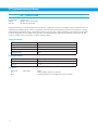
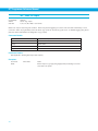
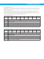
I/O Commands
Command
Description
NV
write
only
AD
Analog Deadband
•
All stepper drives and SRV-DC7
servo drives
AF
Analog Filter
•
All drives
AG
Analog Velocity Gain
•
All stepper drives and SRV-DC7
servo drives
AI
Alarm Input usage
•
All drives
AO
Alarm Output usage
•
All drives
AP
Analog Position Gain
•
All drives
AS
Analog Scaling
•
All stepper drives and SRV-DC7
servo drives
AT
Analog Threshold
•
All drives
AV
Analog Offset
•
All drives
AZ
Analog Zero (Auto Zero)
BD
Brake Disengage Delay time
•
All drives
BE
Brake Engage Delay time
•
All drives
BO
Brake Output usage
•
All drives
DL
Define Limits
•
All drives
EI
Input Noise Filter
•
All drives
FI
Filter Input
•
All drives (Note: not NV on SRVAC5 servos)
FX
Filter Selected Inputs
•
read Immediate
only
Compatibility
All drives
SRV-AC5, STP-AC5, SRV-AC3
15
IQ® Programmer Reference Manual
I/O Commands (continued)
Command
Description
NV
write
only
read Immediate
only
IH
Immediate High Output
•
•
All drives
IL
Immediate Low Output
•
•
All drives
IO
Output Status
•
All drives
IS
Input Status request
•
All drives
MO
Motion Output
OI
On Input
SI
Enable Input usage
SO
Set Output
•
All drives
TI
Test Input
•
Q drives only
WI
Wait on Input
•
All drives
•
•
Compatibility
All drives
•
Q drives only
•
All drives
Communications Commands
Command
Description
NV
write
only
read Immediate
only
BR
Baud Rate
BS
Buffer Status
CE
Communications Error
IF
Immediate Format
•
PB
Power up Baud Rate
•
All drives
PR
Protocol
•
All drives
TD
Transmit Delay
•
All drives
•
Compatibility
All drives
•
All drives
•
All drives
•
All drives
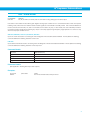
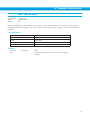
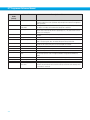
Q Program Commands
Command
Description
AX
Alarm Reset
MT
Multi-Tasking
NO
No Operation
•
Q drives only
OF
On Fault
•
Q drives only
OI
On Input
•
Q drives only
PS
Pause
•
All drives
QC
Queue Call
•
Q drives only
QD
Queue Delete
•
Q drives only
QE
Queue Execute
•
QG
Queue Goto
•
Q drives only
QJ
Queue Jump
•
Q drives only
QK
Queue Kill
•
QL
Queue Load
•
QR
Queue Repeat
•
QS
Queue Save
•
QU
Queue Upload
16
NV
write
only
read Immediate
only
•
Compatibility
All drives
Q drives only
•
Q drives only
Q drives only
•
Q drives only
Q drives only
•
•
Q drives only
•
Q drives only
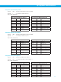
IQ® Programmer Reference Manual
Q Program Commands (continued)
Command
Description
NV
write
only
read Immediate Compatibility
only
QX
Queue Load & Execute
•
Q drives only
SM
Stop Move
•
Q drives only
SS
Send String
•
All drives
TI
Test Input
•
Q drives only
WD
Wait Delay using Data Register
•
Q drives only
WI
Wait for Input
•
All drives
WM
Wait for Move to complete
•
Q drives only
WP
Wait for Position in complex move
•
Q drives only
WT
Wait Time
•
Q drives only
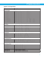
Register Commands
Command
Description
NV
write
only
read Immediate
only
Compatibility
CR
Compare Register
•
Q drives only
DR
Data Register for Capture
•
Q drives only
RC
Register Counter
•
Q drives only
RD
Register Decrement
•
Q drives only
RI
Register Increment
•
RL
Register Load
RM
Register Move
•
RR
Register Read
•
RU
Register Upload
•
RW
Register Write
•
RX
Register Load
R+
Register Addition
•
Q drives only
R-
Register Subtraction
•
Q drives only
R*
Register Multiplication
•
Q drives only
R/
Register Division
•
Q drives only
R&
Register Logical AND
•
Q drives only
R|
Register Logical OR
•
Q drives only
TR
Test Register
•
Q drives only
TS
Time Stamp read
•
Q drives only
Q drives only
•
Q drives only
Q drives only
Q drives only
•
Q drives only
Q drives only
17
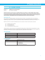
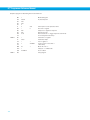
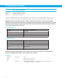
IQ® Programmer Reference Manual
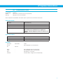
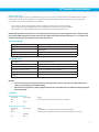
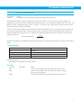
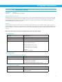
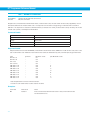
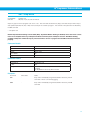
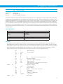
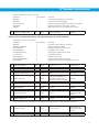
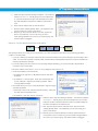
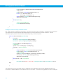
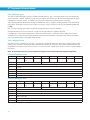
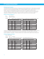
Command Listing
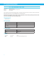
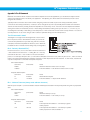
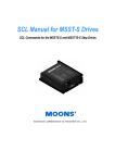
This section is an alphabetical listing of all the commands available with your drive. Each page in this section contains the details
of one available command. Below is a sample of what these pages look like, with an explanation of the information you will find on
each page.
Title - shows the command’s two-letter code
followed by the command’s name.
Compatibility - shows which drives use this
command.
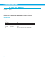
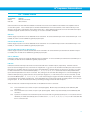
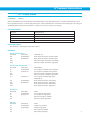
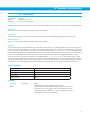
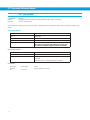
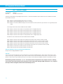
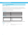
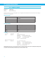
DI - Distance/Position
Compatibility:
Affects:
See also:
Affects - a summary of parameters or other
commands the command affects.
All drives
All move commands
AC, DC, DE and VE commands
See Also - related commands
Sets or requests the move distance in encoder counts (servo) or steps (stepper). The sign of DI indicates move direction: no sign
means CW and “-” means CCW. DI sets both the distance for relative moves, like FL, and the position for absolute moves, like FP.
DI also sets the direction of rotation for jogging (CJ).
Description- an explanation of what the command
does and how it works.
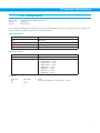
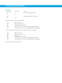
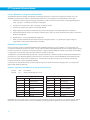
Command Details:
Command Details - shows the command’s
Structure, Type, Usage, Non-Volatile status, and
Register Access. Structure always shows the
two-letter command code followed by the number
of parameters it uses. Not all commands have
parameters, some commands have optional
parameters, and other commands always have a
parameter. Optional parameters are designated by
{ }, and required parameters are designated by (
). Type can be BUFFERED or IMMEDIATE. Usage
can be Read Only, Read/Write, or Write Only. NonVolatile will show if the command can be saved
(YES) or not (NO). Saving Non-Volatile commands
to memory requires the SA (Save) command.
Register Access shows any data registers
associated with the command. If the command
transfers data to a register that is accessible via the
RL and RX commands, that register will be shown
here.
Structure
DI{Parameter #1}
Type
BUFFERED
Usage
READ/WRITE
Non-Volatile
YES
Register Access
“D” (020)
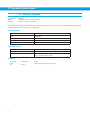
Parameter Details:
Parameter #1
distance
- units
encoder counts (servo) or steps (stepper)
- range
-2,147,483,647 to 2,147,483,647
sign determines direction: “-” for CCW, no sign for CW
Examples:
Command
DI20000
DI
Drive sends
-
DI=20000
Notes
Set distance to 20000 counts in the CW direction
DI-8000
FL
-
-
Set distance to 8000 counts in the CCW direction
Initiate FL move
Parameter Details - shows a description, the units,
and the range of the parameter(s) available with
a given command. Some commands will also
have a Response Details section which shows
how the drive’s response to the given command is
formatted.
Examples - shows what to expect when you
use this command. Under “Command” are the
command strings you would send from a host
controller or write into a stored program. Under
“Drive Sends” are the responses from the drive: no
response from the drive is denoted by “-”. “Notes”
give additional information about the results of the
command string.
18
IQ® Programmer Reference Manual
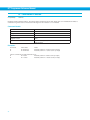
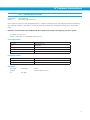
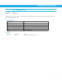
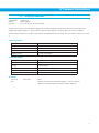
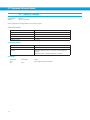
AC - Acceleration Rate
Compatibility:
Affects: See also: All drives
FC, FD, FE, FL, FM, FS, FP, FY, SH commands
AM, DE, DI, DC, VE commands
Sets or requests the acceleration rate used in point-to-point move commands in rev/sec/sec.
Command Details:
Structure
AC{Parameter #1}
Type
BUFFERED
Usage
READ/WRITE
Non-Volatile
YES
Register Access
“A” (017)
Note: Units of AC command and “A” register are
different. See Data Registers section for details of “A”
register.
Parameter Details:
Parameter #1
Acceleration rate
- units
rev/sec/sec (rps/s)
- range
0.167 to 5461.167 (resolution is 0.167 rps/s)
Examples:
Command
AC100
AC
Drive sends
-
AC=100
Notes
Set Acceleration to 100 rev/sec/sec
AC25
DE25
VE1.5
FL20000
-
-
-
-
Set acceleration rate to 25 rev/sec/sec
Set deceleration rate to 25 rev/sec/sec
Set velocity to 1.5 rev/sec
Execute Feed to Length move of 20000 steps
19
IQ® Programmer Reference Manual
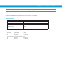
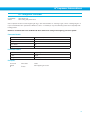
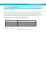
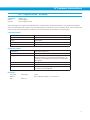
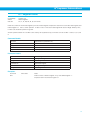
AD - Analog Deadband
Compatibility:
Affects: See also: All stepper drives and SRV servo drives
Analog input
CM command
Sets or requests the analog deadband value in millivolts. The deadband value is the zone around the “zeroed” value of the analog
input. This deadband defines the area of the analog input range that the drive should interpret as “zero”. This zero point can be
used as the zero velocity point in analog velocity mode, or as the zero position point in analog position mode (see CM command).
The deadband is an absolute value that in usage is applied to either side of the zero point.
Note that in Analog Positioning mode (CM22), the AD setting is used as a hysteresis value rather than a standard deadband
setting. As such, it will work over the entire analog range, not just at zero volts.
Command Details:
Structure
AD{Parameter #1}
Type
BUFFERED
Usage
READ/WRITE
Non-Volatile
YES
Register Access
Setting the AD command will affect the contents of the “a”
(Analog Command) register
Parameter Details:
Parameter #1
Analog deadband value
- units
millivolts
- range
0 - 255
Examples:
Command
AD100
AD
20
Drive sends
-
AD=100
Notes
Set analog deadband to 0.1 volts
IQ® Programmer Reference Manual
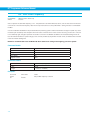
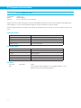
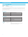
AF - Analog Filter
Compatibility:
Affects:
See also:
All drives
All commands using the analog inputs
IA, CM commands
Applies a digital filter to the analog input(s). This is a simple single pole filter that rolls off the analog input. The filter value of the AF
command is related to the desired value of the analog filter in Hz by the following equation:
Filter value = 72090 / [ (1400 / x ) + 2.2 ]
where x = desired value of the analog filter in Hz
Command Details:
Structure
AF{Parameter #1}
Type
BUFFERED
Usage
READ/WRITE
Non-Volatile
YES
Register Access
Setting the AF command will affect the responsiveness of
the “a”, “j”, and “k” registers to changes in analog voltage
Parameter Details:
Parameter #1
Filter value
- units
integer (see formula above)
- range
0 - 32767* (0 disables the filter)
* An AF value of 28271 equates to 4000.425 Hz. Setting the AF command to anything higher than 28271 has a negligible
effect on the analog filter. In other words, the maximum value of the filter is approximately 4000 Hz.
Examples:
Command
AF5000
AF
Drive sends
-
AF=5000
Notes
Make the analog input bandwidth 114.585 Hz
21
IQ® Programmer Reference Manual
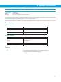
AG - Analog Velocity Gain
Compatibility:
Affects: See also: All stepper drives and SRV servo drives
Analog velocity modes
CM command
Sets or requests the gain value used in analog velocity / oscillator modes. The gain value is used to establish the relationship
between the analog input and the motor speed. The units are 0.25 rpm. For example, if the analog input is scaled to 0 - 5 volt
input and the gain is set to 2400, when 5 volts is read at the analog input the motor will spin at 10 rps. TIP: To set the analog
velocity gain to the desired value, multiply the desired motor speed in rps by 240, or the desired motor speed in rpm by 4.
Command Details:
Structure
AG{Parameter #1}
Type
BUFFERED
Usage
READ/WRITE
Non-Volatile
YES
Register Access
None
Parameter Details:
Parameter #1
Analog velocity gain value
- units
0.25 rpm
- range
-32767 to 32767
Examples:
Command
AG3000
AG
22
Drive sends
-
AG=3000
Notes
Set top speed of analog velocity mode to 12.5 rps
IQ® Programmer Reference Manual
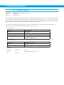
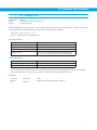
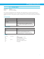
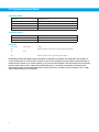
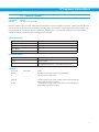
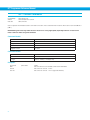
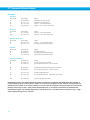
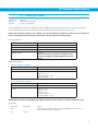
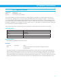
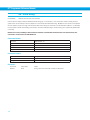
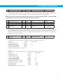
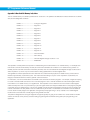
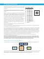
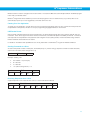
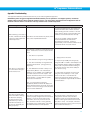
AI - Alarm Reset Input
Compatibility:
Affects: See also: All drives, see below
Alarm Reset input usage
AL, CM, DL, SI, SD commands
SRV-AC3, SRV-AC5, SRV-DC7, STP-10
Defines the function of the X4 input. This input can be used to clear a drive fault and reset the Alarm Code (see AL command).
When the Alarm Reset function is not needed at input X4, such as when operating with a host controller where faults and alarms
can be cleared via serial commands, it may be useful to reconfigure X4 as a general purpose input, which allows it to be used by
other types of input commands.
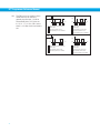
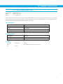
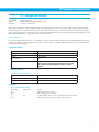
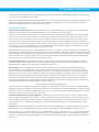
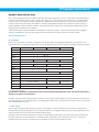
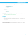
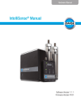
There are three Alarm Reset Input states that can be defined with the AI command:
AI1: For normal operation the X4 input must
be open (inactive, high). Alarm reset
occurs when the input is closed (active,
low). This is an edge-triggered event.
If the switch is closed when an alarm is
activated no reset will occur. The input
must be opened (inactive, high) and
then closed to reset the alarm.
AI2: For normal operation the X4 input
must be closed (active, low). Alarm
reset occurs when the input is opened
(inactive, high). This is an edgetriggered event. If the switch is open
when an alarm is activated no reset will
occur. The input must be closed and
then opened to reset the alarm.
AI3: Input is not used for Alarm Reset and
can be used as a general purpose
input.
AI1
(high)
(high)
(low)
time
A B
A
B
C
C
(low)
D
time
A B
Input is open, normal operation
Alarm occurs
Input closed, alarm is reset
A
B
C
D
(high)
(high)
C
D E
Input is closed
Alarm occurs
Input opened, no reset occurs
Input closed, alarm is reset
AI2
(low)
time
A B
A
B
C
C
(low)
D
Input is closed, normal operation
Alarm occurs
Input opened, alarm is reset
time
A B
A
B
C
D
C
D
E
Input is open
Alarm occurs
Input closed, no reset occurs
Input opened, alarm is reset
ITM-23Q, STP-*-*-S
Defines the EN input as an Alarm Reset Input. If you want to use the EN input as an Alarm Reset input you can define it as such
in two ways, with the Bimba IQ® Stepper software, or with the AI command. AI takes no effect if the drive is set in Command
Mode (CM) 13, 14, 17 or 18, because these modes use the EN input as a speed change input and take precedence over the AI
command. Also, setting the SI command after setting the AI command reassigns the EN input to drive enable usage and turns
off any alarm reset usage (AI3). In other words, the AI and SI commands, as well as Command Modes (CM) 13, 14, 17 and 18
each assign a usage to the EN input. Each of these must exclusively use the EN input.
There are three Alarm Reset Input states that can be defined with the AI command:
AI1: For normal operation the EN input must be open (inactive, high). Alarm reset occurs when the EN input is closed
(active, low). This is an edge-triggered event. If the switch is closed when an alarm is activated no reset will occur.
The input must be opened and then closed to reset the alarm. After the alarm is cleared, the drive will be enabled
when the input is opened again.
AI2 : For normal operation the EN input must be closed (active, low). Alarm reset occurs when the input is opened (inactive,
high). This is an edge-triggered event. If the switch is open when an alarm is activated no reset will occur. The input
must be closed and then opened to reset the alarm. After the alarm is cleared, the drive will be enabled when the
input is closed again.
23
IQ® Programmer Reference Manual
AI3: The EN Input is not used for Alarm
Reset and may be used as a
general purpose input. AI will be
automatically set to 3 if CM is set
to 13, 14, 17, or 18 or if SI is set to
either 1 or 2 after the AI command is
set.
AI1
(high)
(high)
(low)
time
A B
A
B
C
D
C
(low)
D
time
A B
Input is open, normal operation
Alarm occurs
Input closed, alarm is reset
Input opened, drive is re-enabled
A
B
C
D
E
(high)
(high)
C
D E
Input is closed
Alarm occurs
Input opened, no reset occurs
Input closed, alarm is reset
Input opened, drive is re-enabled
AI2
(low)
time
A B
A
B
C
D
24
C
(low)
D
Input is closed, normal operation
Alarm occurs
Input opened, alarm is reset
Input closed, drive is re-enabled
time
A B
A
B
C
D
E
C
D
E
Input is open
Alarm occurs
Input closed, no reset occurs
Input opened, alarm is reset
Input closed, drive is re-enabled
IQ® Programmer Reference Manual
AL - Alarm Code
Compatibility:
See also:
All drives
AI, AR, AX commands, Appendix
Reads back an equivalent hexadecimal value of the Alarm Code’s 16-bit binary word.
Command Details:
Structure
AL
Command Type
IMMEDIATE
Usage
READ ONLY
Non-Volatile
NO
Register Access
“f” (054)
Note: response to AL command is a different format
than the response to the RLf command. See Appendix
F for details
Units
Hexadecimal value of 16-bit binary word (see below)
Response Details:
Hex Value
SRV-AC5
0001
SRV-DC7
STP-10
Position Limit
0002
CCW Limit
0004
CW Limit
Over Temp
0008
0010
Excess Regen*
Internal Voltage
Under Voltage*
Under Voltage
Under Voltage
Over Current
0020
0040
Bad Hall Sensor
0200
Internal Voltage
Under Voltage
Open Motor Winding
(not used)
Bad Encoder
0400
Comm Error
0800
Bad Flash
1000
Wizard Failed
2000
Current Foldback
4000
8000
Internal Voltage
Over Voltage
0080
0100
ITM-23Q
No Move
(not used)
(not used)
Blank Q Segment
No Move
(not used)
NOTE: Items in “bold italic” represent Drive Faults, which automatically disable the motor. Use the OF command
in a Q Program to branch on a Drive Fault.
NOTE: See Appendix for more detailed information on Alarm Codes.
Examples:
Command
AL
AL
AL
Drive sends
AL=0000
AL=0001
AL=0201
Notes
No alarms
Position limit alarm
Position limit and bad encoder signal alarms
25
IQ® Programmer Reference Manual
AM - Max Acceleration
Compatibility:
Affects:
See also: All drives
ST, SK , SM, QK commands; analog velocity and oscillator modes
VM command
Sets or requests the maximum acceleration/deceleration allowed when using analog velocity and oscillator modes. Also sets the
deceleration rate used when an end-of-travel limit is activated during a move or when an ST (Stop) or SK (Stop & Kill) command is
sent.
Command Details:
Structure
AM{Parameter #1}
Type
BUFFERED
Usage
READ/WRITE
Non-Volatile
YES
Register Access
None
Parameter Details:
Parameter #1
Maximum acceleration/deceleration
- units
rev/sec/sec (rps/s)
- range
0.167 - 5461.167 (resolution is 0.167 rps/s)
Examples:
Command
AM2000
AM
26
Drive sends
-
AM=2000
Notes
Set maximum acceleration/deceleration values to 2000 rev/sec/sec.
IQ® Programmer Reference Manual
AO - Alarm Output
Compatibility:
Affects:
See also:
All drives
Alarm Output usage
AI, BO, MO, SD, SI commands
SRV-AC5, SRV-DC7, STP-10, SRV-AC3, STP-AC5
Defines usage of digital output Y3. Normally this output is used to indicate an Alarm caused by a Drive Fault. This output can
being reconfigured as a general purpose output for use with other types of output commands. There are three states that can be
defined:
AO1: Output is closed (active, low) when a Drive Fault is present.
AO2: Output is open (inactive, high) when an Drive Fault is present.
AO3: Output is not used as an Alarm Output and can be used as a general purpose output.
ITM-23Q
Defines the drive’s digital output as an Alarm Output. The output of a drive can be assigned to one of five functions: Alarm Output,
Brake Output, Motion Output, Tach Output or General Purpose Output. Each of these functions must exclusively use the output,
so only one function is allowed. There are two ways to define the function of this output: via the Bimba IQ® Stepper or via SCL
commands. To set the output as an Alarm Output, use the AO command and one of the codes below. There are three Alarm
Output states that can be defined with the AO command:
AO1: Output is closed (active, low) when a Drive Fault is present.
AO2: Output is open (inactive, high) when a Drive Fault is present.
AO3: Output is not used as an Alarm Output and can be used for another automatic output function or as a general purpose
output.
NOTE: Setting the AO command to 1 or 2 overrides previous assignments of this output’s function. Similarly, if you
use the BO or MO command to set the function of the output after setting the AO command to 1 or 2, usage of the
output will be reassigned and AO will be automatically set to 3.
Command Details:
Structure
AO{Parameter #1}{Parameter #2 (Flex I/O only)}
Type
BUFFERED
Usage
READ/WRITE
Non-Volatile
YES
Register Access
None
27
IQ® Programmer Reference Manual
Parameter Details:
Parameter #1
Output Usage (see above)
- units
integer code
- range
1, 2 or 3
Parameter #2 (Flex I/O only)
I/O Point (if applicable, see note below)
- units
integer code
- range
1-4
NOTES:
• For drives with Flex I/O, the SD command must be executed to set an I/O point as an input or output before
that output can be designated as the Alarm Output.
• Parameter #2 only applies to drives equipped with Flex I/O. Parameter #2 is not defined for drives equipped
with standard I/O.
Examples:
All drives with standard I/O:
Command
Drive sends
AO1
-
AO
AO=1
Drives with Flex I/O only:
Command
Drive sends
SD4O
-
AO14
-
occurs.
AO
AO=14
Notes
Alarm Output will close when a Drive Fault occurs
Notes
Configures I/O 4 as output (see SD command for details)
Alarm Output is mapped to output #4, and will close when a Drive Fault NOTE: When working with digital inputs and outputs it is important to remember the designations low and high. If
current is flowing into or out of an input or output, i.e. the circuit is energized, the logic state for that input/output is
defined as low or closed. If no current is flowing, i.e. the circuit is de-energized, or the input/output is not connected,
the logic state is high or open. A low state is represented by the “L” character in parameters of commands that
affect inputs/outputs. For example, WI3L means “wait for input 3 low”, and SO1L means “set output 1 low”. A high
state is represented by the “H” character.
28
IQ® Programmer Reference Manual
AP - Analog Position Gain
Compatibility:
Affects:
See also: All drives
CM22 (Analog Positioning Command Mode)
AD, AF, AZ, CM, SF commands
Sets or requests the analog Input gain that relates to motor position when the drive is in analog position command mode (see CM
command, parameter value 22). Gain value sets the commanded position when the analog input is at the configured full scale
value. Bimba IQ® Servo (SRV-AC5, SRV-DC7), or Bimba IQ® Stepper (STP-10,
ITM-23Q) can be used to configure the analog inputs for the desired input type, scaling and offsetting.
Command Details:
Structure
AP{Parameter #1}
Type
BUFFERED
Usage
READ/WRITE
Non-Volatile
YES
Register Access
“X” (040)
Parameter Details:
Parameter #1
Analog position gain value
- units
encoder counts
- range
0 - 32767
Examples:
Command
AP8000
AP
Drive sends
-
AP=8000
Notes
Position range over full scale of analog input is 8000 steps
29
IQ® Programmer Reference Manual
AR - Alarm Reset (Immediate)
Compatibility:
Affects:
See also:
All drives
Alarm Code
AL, ME, MD commands
Clears Alarms and Drive Faults. If an Alarm or Drive Fault condition persists after sending the AR command the Alarm is not
cleared.
NOTE: Does not re-enable the drive. Use ME (Motor Enable) command to re-enable drive.
Command Details:
Structure
AR
Type
IMMEDIATE
Usage
WRITE ONLY
Non-Volatile
NO
Register Access
None
Examples:
Command
AR
30
Drive sends
-
Notes
Reset Drive Fault and clear Alarm Code (if possible)
IQ® Programmer Reference Manual
AS - Analog Scaling
Compatibility:
Affects:
See also:
All stepper drives and SRV servo drives
Analog input
CM command
Sets or requests the analog input scaling setting. This is a code that determines what type of analog input scaling is desired. The
codes for selecting the various settings are in the Details table below.
Command Details:
Structure
AS{Parameter #1}
Type
BUFFERED
Usage
READ/WRITE
Non-Volatile
YES
Register Access
None
Parameter Details:
Parameter #1
Code
- units
integer number
- range
0 = single-ended +/- 10 volts
1 = single-ended 0 - 10 volts
2 = single-ended +/- 5 volts
3 = single-ended 0 - 5 volts
4 = differential +/- 10 volts
5 = differential 0 - 10 volts
6 = differential +/- 5 volts
7 = differential 0 - 5 volts
Examples:
Command
AS2
AS
Drive sends
-
AS=2
Notes
Analog input scaling set to single-ended +/- 5 volts
31
IQ® Programmer Reference Manual
AT - Analog Threshold
Compatibility:
Affects:
See also:
All drives
All “Feed to Sensor” type commands
AF, AZ, FS, FY, FD commands
Sets or requests the Analog Input Threshold that is used by the “Feed to Sensor” command. The threshold value sets the Analog
voltage that determines a sensor state or a trigger value.
Command Details:
Structure
AT{Parameter #1}
Type
BUFFERED
Usage
READ/WRITE
Non-Volatile
YES
Register Access
“Y” (041)
Parameter Details:
Parameter #1
Analog threshold value
- units
volts
- range
STP-AC5, SRV-AC3: -10.000 to 10.000
STP-*-*-S, ITM: 0.000 to 5.000
Examples:
Command
AT4.5
AT
32
Drive sends
-
AT=4.5
Notes
Analog input threshold set to 4.5 volts
IQ® Programmer Reference Manual
AV - Analog Offset Value
Compatibility:
Affects:
See also:
All drives
All Analog input functions
AF, AP, AZ, CM & Feed commands
Sets or requests the analog offset value in volts.
Command Details:
Structure
AV{Parameter #1}
Type
BUFFERED
Usage
READ/WRITE
Non-Volatile
YES
Register Access
“Z” (042)
Note: Units of AV command are different than units
of “Z” register; see Data Registers section for more
details
Parameter Details:
Parameter #1
Analog offset value
- units
Volts
- range
SRV-AC5, SRV-DC7, STP-10, STP-AC5, SRV-AC3: -10.000
to 10.000
ITM-23Q: -5.000 to 5.000
Examples:
Command
AV0.25
AV
Drive sends
-
AV=0.25
Notes
Set analog offset to 0.25 Volts
33
IQ® Programmer Reference Manual
AX - Alarm Reset (Buffered)
Compatibility:
Affects:
See also:
All drives
Alarm Code
AR, ME, OF, WT Commands
Clears Alarms and Drive Faults. This command functions the same as AR (Alarm Reset) but is a Buffered type command.
Typically used in conjunction with OF within a Q program. Please note that while immediately executing AX will clear the alarm
code, it does not guarantee that the condition that caused the alarm has been resolved. Therefore it is recommended to include a
short delay or wait for user input before clearing the alarm and resuming normal operation.
In addition to clearing alarms and faults, the AX command resets the LED blink timer. As such, if the AX command is used within a
tight loop in a Q program, the LED may actually appear to be solid green.
NOTE: Does not re-enable the drive. Use ME (Motor Enable) command to re-enable drive.
Command Details:
Structure
AX
Type
BUFFERED
Usage
WRITE ONLY
Non-Volatile
NO
Register Access
None
Examples:
Command
34
Drive sends
Notes
In segment 1 of a Q program...
OF9
-
When a drive fault occurs load and execute program segment 9
In segment 9 of the same Q program...
WT0.1
-
AX
-
ME
-
QX1
-
Short delay to allow the system to settle
Alarm reset
Motor enable
Load and execute segment 1, which will also reset the OF function.
IQ® Programmer Reference Manual
AZ - Analog Zero
Compatibility:
Affects:
See also:
All drives
All Analog input functions
AF, AP, AV, CM & Feed commands
Activates the analog “auto offset” algorithm. It is useful in defining the current voltage present at the analog input as the zero
reference point, or offset.
Command Details:
Structure
AZ
Type
BUFFERED
Usage
WRITE ONLY
Non-Volatile
NO
Register Access
None
Examples:
Command
AZ
Drive sends
-
Notes
Start analog offset algorithm
Example: Apply 1 VDC across the AIN and GND terminals of the drive. Then send the AZ command to the drive. Next apply 4
VDC across the AIN and GND terminals. Send the IA command and the response will be very close to IA=3.00 (or 4 - 1 VDC).
35
IQ® Programmer Reference Manual
BD - Brake Disengage Delay
Compatibility:
Affects:
See also:
All drives
All “F” (Feed) and Jog commands.
BE command
This command only takes effect if the BO command is set to 1 or 2. After a drive is enabled this is the time value that may delay a
move waiting for the brake to disengage. When beginning a move the delay value must expire before a move can take place. The
delay timer begins counting down immediately after the drive is enabled and the brake output is set. The BD command sets a time
in milliseconds that a move may be delayed.
Command Details:
Structure
BD{Parameter #1}
Type
BUFFERED
Usage
READ/WRITE
Non-Volatile
YES
Register Access
None
Parameter Details:
Parameter #1
Delay time
- units
seconds
- range
0 - 32.767
Examples:
Command
BD0.2
BD
36
Drive sends
-
BD=0.2
Notes
Sets brake disengage delay to 200 ms
IQ® Programmer Reference Manual
BE - Brake Engage Delay
Compatibility:
Affects:
See also:
All drives
All “F” (Feed) and Jog commands.
BD command
This command only takes effect if the BO command is set to 1 or 2. After a drive is commanded to be disabled, this is the time
value that delays the actual disabling of the driver output. When using the dedicated brake output (see BO command) the output
is activated immediately with the disable command, then the drive waits the delay time before turning off the motor current.
Command Details:
Structure
BE{Parameter #1}
Type
BUFFERED
Usage
READ/WRITE
Non-Volatile
YES
Register Access
None
Parameter Details:
Parameter #1
Delay time
- units
seconds
- range
0 - 32.767
Examples:
Command
BE0.25
BE
Drive sends
-
BE=0.25
Notes
Sets brake engage delay to 250 ms
37
IQ® Programmer Reference Manual
BO - Brake Output
Compatibility:
Affects:
See also:
All drives
Function of digital output
AI, AO, BD, ME, MD, MO, SD, SI commands
NOTE: The digital output circuits available on Bimba drives are not sized for directly driving a typical holding brake.
An external relay must be wired in circuit between the digital output of the drive and the holding brake. See the
appropriate drive hardware manual for an example wiring diagram.
SRV-AC5, SRV-DC7, STP-10
Defines usage of digital output Y1 as the Brake Output, which can be used to automatically activate and deactivate a holding
brake. Output Y1 can also be configured as a general purpose output for use with other types of output commands. There are
three states that can be defined:
BO1: Output is closed (energized) when drive is enabled, and open when the drive is disabled.
BO2: Output is open (de-energized) when drive is enabled, and closed when the drive is disabled.
BO3: Output is not used as a Brake Output and can be used as a general purpose output.
ITM-23Q
Defines the drive’s digital output as a Brake Output. The output of a drive can be assigned to one of five functions: Alarm Output,
Brake Output, Motion Output, Tach Output, or General Purpose Output. Each of these functions must exclusively use the output,
so only one function is allowed. There are two ways to define the function of this output: via Bimba IQ® Stepper or via SCL
commands. To set the output as a Brake Output, use the BO command and one of the codes below.
BO1: Output is closed (active, low) when the drive is enabled, and open when the drives is disabled.
BO2: Output is open (inactive, high) when the drive is enabled, and closed when the drive is disabled.
BO3: Output is not used as a Brake Output and can be used for another automatic output function or as a general purpose
output.
STP-AC5, SRV-AC3
Defines usage of digital output Y2 as the Brake Output, which can be used to automatically activate and deacti¬vate a holding
brake. Output Y2 can also be configured as a Motion Output, a Tach Output, or a General Purpose output for use with other types
of output commands. There are three states that can be defined:
BO1: Output is closed (energized) when drive is enabled, and open when the drive is disabled.
BO2: Output is open (de-energized) when drive is enabled, and closed when the drive is disabled.
BO3: Output is not used as a Brake Output and can be used as a general purpose output.
38
IQ® Programmer Reference Manual
STP-AC5, SRV-AC3
Defines usage of digital output Y2 as the Brake Output, which can be used to automatically activate and deactivate a holding
brake. Output Y2 can also be configured as a Tach Output, or a General Purpose output for use with other types of output
commands. There are three states that can be defined:
BO1: Output is closed (energized) when drive is enabled, and open when the drive is disabled.
BO2: Output is open (de-energized) when drive is enabled, and closed when the drive is disabled.
BO3: Output is not used as a Brake Output and can be used as a general purpose output.
NOTE: Setting the BO command to 1 or 2 overrides previous assignments of this output’s function. Similarly, if you
use the AO or MO command to set the function of the output after setting the BO command to 1 or 2, usage of the
output will be reassigned and BO will be automatically set to 3.
Command Details:
Structure
BO{Parameter #1}{Parameter #2 (Flex I/O only}
Type
BUFFERED
Usage
READ/WRITE
Non-Volatile
YES
Register Access
None
Parameter Details:
Parameter #1
Output Usage (see above)
- units
integer code
- range
1, 2 or 3
Parameter #2 (Flex I/O only)
I/O Point (if applicable, see note below)
- units
integer code
- range
1-4
NOTES:
• For drives with Flex I/O, the SD command must be executed to set an I/O point as an output before that
output can be assigned as the Brake Output.
• Parameter #2 only applies to drives equipped with Flex I/O. Parameter #2 is not defined for drives equipped
with standard I/O.
Examples:
All drives with standard I/O:
Command
Drive sends
BO1
-
BO
BO=1
Drives with Flex I/O only:
Command
Drive sends
SD4O -
BO14
-
enabled
BO
BO=14
Notes
Brake Output will be closed when drive is enabled
Notes
Configures I/O 4 as output (see SD command for details)
Brake Output is mapped to I/O point 4 and will be Closed when drive is 39
IQ® Programmer Reference Manual
BR - Baud Rate
Compatibility:
Affects:
See also:
All drives
Serial communications
TD, PB, PM, PR commands
Sets or requests the bit rate (baud) for serial communications. At power up a drive will send its power-up packet at 9600 baud.
If a response from a host system (such as a software application from Bimba) is not detected after 1 second and the drive
is configured for SCL or Q operation (see PM command) the drive will set the baud rate according to the value stored in the
Baud Rate NV parameter. A Host system can set the baud rate at anytime using this command. See Appendix B, “Host Serial
Communications” for details.
NOTE 1: Setting the value takes effect immediately.
NOTE 2: Due to processor speed limitations, -Q drives will accept parameter values of 1-5.
Command Details:
Structure
BR{Parameter #1}
Type
BUFFERED
Usage
READ/WRITE
Non-Volatile
YES
Register Access
None
Parameter Details:
Parameter #1
Baud rate (see above)
- units
integer code
- range
1 = 9600 bps
2 = 19200
3 = 38400
4 = 57600 (-S and -Q drives only)
5 = 115200 (-S and -Q drives only)
Examples:
Command
BR2
BR
40
Drive sends
-
BR=2
Notes
Baud rate is immediately set to 19200
IQ® Programmer Reference Manual
BS - Buffer Status
Compatibility:
See also:
All drives
CT, PS commands
Requests from the drive the number of available command locations in the command buffer. This technique simplifies sending
commands by eliminating the need to calculate if there is enough space in the buffer for a command. If the drive responds with at
least a “1”, a command can be sent.
If a drive responds to the BS command with the value “63” it means the buffer is empty. If a “0” is returned the buffer is full and no
more buffered commands can be accepted (a buffer overflow will occur if another command is sent).
Command Details:
Structure
BS
Type
IMMEDIATE
Usage
READ ONLY
Non-Volatile
NO
Register Access
None
Units
Empty command spaces in buffer
Examples:
Command
BS
Drive sends
BS=20
Notes
There is room in the buffer for 20 more commands
41
IQ® Programmer Reference Manual
CA - Change Acceleration Current
Compatibility:
Affects:
See also:
ITM-23Q Integrated Stepper Motors
Motor accel/decel current and torque
PA, CC, PC commands
Sets or requests the accel/decel current setting (“peak of sine”) of the stepper drive, also known as the peak current. CA will only
accept parameter values equal to or larger than the current CC setting.
NOTE: CA has no effect in Command Mode 7 (CM7 - Step and Direction mode).
Command Details:
Structure
CA{Parameter #1}
Type
BUFFERED
Usage
READ/WRITE
Non-Volatile
YES
Register Access
“M” (029)
Note: The CA command uses different units than the
“M” register; see Data Registers section for details
Parameter Details:
Parameter #1
Accel/Decel Current
- units
amps (resolution is 0.01 amps)
- range
ITM-23Q: 0 - 5.0
Configurator software may also be used to set all current levels.
Example:
STM17, STM23
Command
CA1.75
CA
42
Drive Sends
-
CA=1.75
Notes
Set accel/decel current to 1.75 amps (peak of sine)
IQ® Programmer Reference Manual
CC - Change Current
Compatibility:
Affects:
See also:
All drives
Motor current and torque
CA, CI, CP, PC commands
SRV-AC5, SRV-DC7
Sets or requests the continuous (RMS) current setting of the servo drive.
STP-10, ITM-23Q
Sets or requests the current setting (“peak of sine”) of the stepper drive, also known as the running current. The range of the
CC command may be limited from the ranges shown in the Parameters table below based on the settings defined in the Bimba
IQ® Stepper software. Use Bimba IQ® Stepper to select a motor and set the maximum current setting. Note that setting CC
automatically sets CI to 50% of CC. If a CI value different than 50% of CC is needed be sure to always set CI after setting CC.
Command Details:
Structure
CC{Parameter #1}
Type
BUFFERED
Usage
READ/WRITE
Non-Volatile
YES
Register Access
“N” (030)
Note: The CC command uses different units than the
“N” register; see Data Registers section for details
Parameter Details:
SRV drives
Parameter #1
Continuous current setting
- units
amps rms (resolution is 0.01 amps)
- range
SRV-AC5: 0 - 5.0
SRV-DC7: 0 - 7.0
SRV-AC5 (120V): 0 - 3.5
SRV-AC5 (220V): 0 - 1.8
STP and ITM drives
Parameter #1
Running current
- units
amps (resolution is 0.01 amps)
- range*
STP-10: 0 - 10.0
ITM-23Q: 0 - 5.0
STP-AC5 (120): 0 - 5
STP-AC5 (220): 0 - 2.55
*Current setting in stepper drives depends on the selected motor. Use IQ® Stepper software to select a motor
and set the maximum current setting.
43
IQ® Programmer Reference Manual
Examples:
44
SRV
Command
CC4.50
CC
Drive sends
-
CC=4.5
Notes
Set continuous current to 4.5 amps rms
STP-AC5, ITM
Command
CC3
CI
CI1
Drive sends
-
CI=1.5
-
Notes
Set running current to 3.0 amps
CI automatically set to 1.5 amps along with CC3 command
Set idle current to 1.0 amps
IQ® Programmer Reference Manual
CD - Idle Current Delay Time
Compatibility:
Affects:
See also:
Stepper drives only
Motor current at rest
CC, CI commands
Sets or requests the amount of time the drive will delay before transitioning from full current (CC) to idle current (CI). This transition
is made after a step motor takes the final step of a move. Operating in any form of pulse & direction mode the drive will reset the
idle current delay timer each time a step pulse is received by the drive.
Command Details:
Structure
CD{Parameter #1}
Type
BUFFERED
Usage
READ/WRITE
Non-Volatile
YES
Register Access
None
Parameter Details:
Parameter #1
Delay time
- units
seconds
- range
0.00 to 10.00
Examples:
Command
CD0.4
CD
Drive sends
-
CD=0.4
Notes
Idle current delay time set to 0.4 seconds
45
IQ® Programmer Reference Manual
CE - Communication Error
Compatibility:
See also:
All drives
AL command
Requests the hexadecimal equivalent of the communication error’s 8-bit binary word. The presence of a comm error will also be
shown in the Alarm Code (AL command) as well as the status LEDs at the front of the drive (Appendix F). Bit assignments for the
8-bit word are shown in the Response Details table below.
Command Details:
Command Type
IMMEDIATE
Usage
READ ONLY
Non-Volatile
NO
Register Access
None
Response Details:
Response
Communication error code
- units
hexadecimal code
- range
bit 0 = parity flag error
bit 1 = framing error
bit 2 = noise flag error
bit 3 = overrun error
bit 4 = Rx buffer full
bit 5 = Tx buffer full
bit 6 = bad SPI op-code
bit 7 = Tx time-out
Examples:
Command
CE
CE
46
Drive sends
CE=0010
CE=0002
Notes
Rx buffer full
Framing error
IQ® Programmer Reference Manual
CF - Anti-resonance Filter Frequency
Compatibility:
Affects:
See also:
Stepper drives only
Mid-range performance of step motors
CG command
Sets or requests the anti-resonance filter frequency setting. This setting is in Hz and works in conjunction with the anti-resonance
filter gain setting (CG) to cancel instabilities due to mid-band resonance.
NOTE: We strongly suggest using IQ® Stepper software application to set this value by entering as accurate a load
inertia value as possible in the motor settings window.
Command Details:
Structure
CF{Parameter #1}
Type
BUFFERED
Usage
READ/WRITE
Non-Volatile
YES
Register Access
None
Parameter Details:
Parameter #1
Filter frequency
- units
Hz
- range
1 - 2000
Examples:
Command
CF1400
CF
Drive sends
-
CF=1400
Notes
Set anti-resonance filter frequency to 1400 Hz
47
IQ® Programmer Reference Manual
CG - Anti-resonance Filter Gain
Compatibility:
Affects:
See also:
Stepper drives only
Mid-range performance of step motors
CF command
Sets or requests the anti-resonance filter gain setting. This setting is unit-less and works in conjunction with the anti-resonance
filter frequency setting (CF) to cancel instabilities due to mid-band resonance.
NOTE: We strongly suggest using IQ® Stepper software application to set this value by entering as accurate a load
inertia value as possible in the motor settings window.
Command Structure:
CG{Parameter #1}
Command Details:
Structure
CG{Parameter #1}
Type
BUFFERED
Usage
READ/WRITE
Non-Volatile
YES
Register Access
None
Parameter Details:
Parameter #1
Filter gain
- units
integer number
- range
0 - 32767
Examples:
Command
CG800
CG
48
Drive sends
-
CG=800
Notes
Set anti-resonance filter gain to 800
IQ® Programmer Reference Manual
CI - Change Idle Current
Compatibility:
Affects:
See also:
Stepper drives only
Motor current at standstill, holding torque
CC, PI, CD commands
Idle current is the level of current supplied to each motor phase when the motor is not moving. Using an idle current level lower
than the running motor current level (see CC command) aids in motor cooling. A common level used for the idle current setting is
50% of the running current. After a motor move, there is a time delay after the motor takes its last step before the reduction to the
idle current level takes place. This delay is set by the CD command.
STP-10, ITM-23Q
CI cannot be greater than 90% of CC. If you attempt to set CI to a higher value than this CI is automatically limited to 90% of CC.
Furthermore, setting CC automatically sets CI to 50% of the CC value. If a CI value different than 50% of CC is needed be sure to
always set CI after setting CC.
Command Details:
Structure
CI{Parameter #1}
Type
BUFFERED
Usage
READ/WRITE
Non-Volatile
Yes
Register Access
“O” (031)
Note: The CI command uses different units than the
“O” register; see Data Registers section for more
details
Parameter Details:
STP-10, ITM-23Q, STP-AC5
Parameter #1
Idle current
- units
amps
- range
0 - 90% of running current
Examples:
STP-10, ITM-23Q, STP-AC5
Command
Drive sends
CI2
-
CC2
-
CI
CI=1
CI1.8
-
Notes
Set idle current to 2 amps
Set running current to 2 amps
CI automatically set to 1 amp to match 50% of CC2 command
Set idle current to 1.8 amps, or 90% of last CC value
49
IQ® Programmer Reference Manual
CJ - Commence Jogging
Compatibility:
See also:
All drives
JS, JA, JL, SJ, CS and DI commands.
Starts the motor jogging. The motor accelerates up to the jog speed (JS) at a rate defined by the jog accel (JA) command, then
runs continuously until stopped. To stop jogging, use the SJ (Stop Jogging) command for a controlled decel rate (decel rate set
by JL command). For a faster stop, use the ST command (decel rate set by AM command), but beware that if the speed or load
inertia is high, the drive may miss steps, stall, or fault. The jogging direction is set by the last DI command. Use the CS command
to change jog speed and direction while already jogging. CS does not affect JS.
Use in Q Programs (Q drives only)
Within a stored Q program jog moves are most commonly initiated with the CJ command. However, because the SJ and ST
commands are immediate type they cannot be used within a Q program to stop the jog move. So the procedure to stop a jog
move within a Q program involves both the MT (Multi-tasking) and SM (Stop Move) commands. See Examples below for a sample
command sequence.
Command Details:
Structure
CJ
Type
BUFFERED
Usage
WRITE ONLY
Non-Volatile
NO
Register Access
None
Examples:
Command
JA10
JL25
JS1
CJ
CS10
SJ
Drive sends
-
-
-
-
-
-
Notes
Set jog accel to 10 rps/s
Set jog decel to 25 rps/s
Set jog speed to 1 rps
Start jogging with speed set by last JS command
Change jog speed to 10 rps
Stop jogging using decel rate set by last JL command
The following example changes the jog speed during program execution by directly loading a value into the “J” register. This
method allows for dynamically calculated jog speeds, and does not affect the original JS or DI setting. CJ always starts a jog
move using JS and DI, so this is the recommended method of changing speed dynamically during program execution.
Sample Q program sequence
MT1
Turn Multi-tasking ON
FI58
Filter input X5 for 8 processor ticks (2 msec)
WIX5L
Wait for input X5 low
CJ
Commence jogging
RLJ480
Change speed to 2 rev/sec by directly loading the J register. Note, units are 0.25rpm.
WIX5H
Wait for input X5 high
SMD
Stop Move using the decel ramp set by JL
50
IQ® Programmer Reference Manual
CM - Command Mode (AKA Control Mode)
Compatibility:
Affects:
See also:
All drives
Drive mode of operation
PM command
Sets or requests the Command Mode that the drive operates in. For more automated setup of command modes use the
appropriate Bimba IQ® Stepper or Bimba IQ® Servo software application. The most common command mode is Point-to-Point
(21), in which all move commands can be executed. Move commands (like FL, FP, FS, and CJ) can still be executed when the
command mode is set to Step & Direction (7), because the drive will temporarily switch to command mode 21 to execute the
move, then revert back to command mode 7 when the move is finished. However move commands are either ignored or do not
function properly when the command mode is set to any velocity mode (11-18) or the Analog Position mode (22).
WARNING: Changing the Command Mode without proper care may cause the motor to spin at a high rate of speed or
give other unexpected results. For this reason it is suggested that the appropriate IQ® Stepper or IQ® Servo software
application be used to test specific Command Modes first before changing them in the application using the CM
command.
Command Details:
Structure
CM{Parameter #1}
Type
BUFFERED
Usage
READ/WRITE
Non-Volatile
YES
Register Access
“m” (061)
Note: Because a drive can change Command Mode on
it’s own to complete certain moves, the CM command
and the “m” register may not always match.
Parameter Details:
Parameter #1
Command mode
- units
integer code
- range
1 - Commanded Torque (servo only)
2 - Analog Torque (servo only)
7 - Step & Direction
10 - Commanded Velocity (jog mode)
11 - Analog velocity
12 to 18 - (see below)
21 - Point-to-Point
22 - Analog Position
NOTE: In Command Modes 11, 12, 13 and 14, input X2 will function to reverse the direction of motion.
51
IQ® Programmer Reference Manual
Command Modes 12 to 18 are for stepper drives and SRV servo drives only:
12 - Analog velocity mode with input X1 as run/stop input
13 - Analog velocity mode with input X5 (X4 for STP-AC5 drives) as speed change input
14 - Analog velocity mode with input X1 as run/stop input and input X5 (X4 for STP-AC5 drives) as speed change input
15 - Velocity mode (JS for speed)
16 - Velocity mode (JS for speed) with input X1 as run/stop input
17 - Velocity mode (JS for speed) with input X5 (X4 for STP-AC5 drives) as speed change input
18 - Velocity mode (JS for speed) with input X1 as run/stop input and input X5 (X4 for STP-AC5 drives) as speed change input
NOTE: It is recommended to use Configurator or Quick Tuner software for setting up velocity mode operation.
Examples:
52
Command
Drive sends
CM2
-
Notes
Sets the servo drive to Analog Torque mode, at which time there is a
linear relationship between the voltage at the drive’s analog input and the
motor current.
CM7
-
Sets the drive to Step & Direction input mode, which is used for all digital
positioning schemes like Step (Pulse) & Direction, CW/CCW Pulse, and
A/B Quadrature. Use the appropriate IQ® Programmer or IQ® Servo
application to set the proper scheme within this mode.
CM10
-
Sets the drive to Command Velocity, or jog mode, which in practice is
very similar to Point-to-Point mode (CM21). When in CM21 and a jog
command is issued, like CJ, the drive automatically switches to CM10
during the jog move and then back to CM21 when the jog move is
stopped. Conversely, when in CM10 and a feed move is commanded,
like FL, the drive automatically switches to CM21 during the move and
then back to CM10 when the move is finished.
CM10 is most useful with servo drives, and when the JM (Jog Mode) is
set to 2. This puts the drive into a jog mode in which position error is
ignored. Then, when the motor is at rest the drive acts somewhat like a
constant friction device in that a certain amount of torque (set by CC and
CP commands) is required to move the shaft.
CM11
-
Sets the drive to Analog Velocity mode. In servo drives this will be similar
to the Analog Torque mode, where voltage level at the analog input
relates to motor speed. In stepper drives this puts the drive into
continuous oscillator mode, with speed set by the JS command.
CM22
-
Sets the drive to Analog Positioning mode. In this mode it is also
possible to control the position through the use of an external encoder.
IQ® Programmer Reference Manual
CP - Change Peak Current
Compatibility:
Affects:
See also:
Servo drives only
Motor current, especially during acceleration and deceleration
CC, PC, PP commands
Sets or requests the peak (RMS) current setting of the servo drive. Peak current sets the maximum current that should be used
with a given motor. When the motor position requires more than the continuous value, the peak current time calculation is done
using I2/T which integrates current values for more accurate modeling of drive and motor heating. The servo drive will allow peak
current for not more than one second. After one second of operation at peak current the current is reduced to the continuous
current setting (see CC command).
Command Details:
Structure
CP{Parameter #1}
Type
BUFFERED
Usage
READ/WRITE
Non-Volatile
YES
Register Access
“O” (031)
Note: The CP command uses different units than the
“O” register; see Data Registers section for more
details
Parameter Details:
Parameter #1
Peak current limit
- units
amps RMS
- range
SRV-AC5: 0 - 15.0 A
SRV-DC7: 0 - 14.0 A
SRV-AC3 (120V): 0 - 7.5
SRV-AC3 (220V): 0 - 3.75
Examples:
Command
CP9.0
CP
Drive sends
-
CP=9.0
Notes
Peak current is set to 9.0 amps RMS
53
IQ® Programmer Reference Manual
CR - Compare Registers
Compatibility:
Affects:
See also:
Q drives only
Contents of condition code register “h”
RI, RD, RM, RL, QJ commands
Compare the contents of two data registers. The first data register (Parameter #1) is tested by comparing it against the data value
in the second data register (Parameter #2). The result is a condition code that can be used for program conditional processing
(see QJ command). For Example, if the first data register is greater than the second the “greater than” flag is set and the QJGx
command can be used to create a conditional jump.
Command Details:
Structure
CR(Parameter #1)(Parameter #2)
Type
BUFFERED
Usage
WRITE ONLY
Non-Volatile
NO
Register Access
All data registers
Parameter Details:
Parameter #1
First data register assignment
- units
character
- range
All data register assignments
Parameter #2
Second data register assignment
- units
character
- range
All data register assignments
Examples:
Command
Drive sends
CRE1
-
QJG5
-
54
Notes
Compare data register “E” to data register “1”
If “E” register is greater than “1” register jump to line 5 of Q segment,
otherwise proceed to next line.
IQ® Programmer Reference Manual
CS - Change Speed
Compatibility:
Affects:
See also:
All drives
Jog speed while jogging
CJ, JS, JA, JL commands
Sets or requests the jogging speed in rev/sec while jogging. When Jogging using the CJ command the Jog speed can be
changed dynamically by using this command. The sign of CS can be positive or negative allowing the direction of jogging to be
changed dynamically also. Ramping between speeds is controlled by the JA and JL commands. Setting CS does not change JS
or DI.
Command Details:
Structure
CS{Parameter #1}
Type
IMMEDIATE
Usage
READ/WRITE
Non-Volatile
YES
Register Access
“J” (026)
Note: The CS command uses different units than
the “J” register; see Data Registers section for more
details
Parameter Details:
Parameter #1
Jog Speed
- units
rev/sec
- range
SRV-AC5, SRV-DC7, STP-10, STP-AC5, SRV-AC3:
-133.3333 to 133.3333 (resolution is 0.0042)
ITM-23Q: -80.0000 to 80.0000 (resolution is 0.0042)
sign determines direction: “-“ for CCW, no sign for CW
Examples:
Command
JS1
CJ
CS2.5
CS
CS-5
SJ
Drive sends
-
-
-
CS=2.5
-
-
Notes
Set base jog speed to 1 rev/sec
Commence jogging
Set jog speed to CW at 2.5 rev/sec
Displays current Jog speed
Set jog speed to CCW at 5 rev/sec
Stop jogging
55
IQ® Programmer Reference Manual
CT - Continue
Compatibility:
See also:
All drives
PS, ST, SK commands
Resume execution of buffered commands after a PS command has been sent. The PS (Pause) command allows you to pause
execution of commands in the command buffer. After sending the PS command, subsequent commands are buffered in the
command buffer until either a CT command is sent, at which time the buffered commands resume execution in the order they
were received, or until the command buffer is full.
Command Details:
Structure
CT
Type
IMMEDIATE
Usage
WRITE ONLY
Non-Volatile
NO
Register Access
None
Examples:
Command
PS
FL2000
WT.25
FL-2000
CT
56
Drive sends
-
-
-
-
-
Notes
Pause command buffer
CW move, 2000 counts
Wait 0.25 seconds
CCW move, 2000 counts
Resume execution of buffered commands
IQ® Programmer Reference Manual
DA - Define Address
Compatibility:
Affects:
All drives
Drive address for multi-drop communications
Sets individual drive address character for multi-drop RS-485 communications. This command is not required for single-axis
(point-to-point) or RS-232 communications.
Command Details:
Structure
DA{Parameter #1}
Type
BUFFERED
Usage
READ/WRITE
Non-Volatile
YES
Register Access
None
Parameter Details:
Parameter #1
RS-485 network address
- units
character
- range
Valid address characters are:
!“#$%&‘()*+,-./0123456789:;<>?@
Examples:
Command
DA1
DA
Drive sends
-
DA=1
Notes
Set drive address to “1”
57
IQ® Programmer Reference Manual
DC - Change Distance
Compatibility:
Affects:
All drives
FC, FY, FO, FM commands.
Sets or requests the change distance. The change distance is used by various move commands to define more than one
distance parameter. All move commands use the DI command at some level, and many require DC as well. Examples are FC,
FM, FO, and FY. The moves executed by these commands change their behavior after the change distance (DC) has been
traveled. For example, FM is similar to FS, but in an FM move the sensor input is ignored until the motor has moved the number
of steps set by DC. This is useful for masking unwanted switch or sensor triggers. Since DI sets move direction (CW or CCW),
the sign of DC is ignored.
Command Details:
Structure
DC{Parameter #1}
Type
BUFFERED
Usage
READ/WRITE
Non-Volatile
YES
Register Access
“C” (019)
Parameter Details:
Parameter #1
distance
- units
encoder counts
- range
0 to 2,147,483,647
(the sign of negative values is ignored)
Examples:
58
Command
DC80000
DC
Drive sends
-
DC=80000
Notes
Set change distance to 80000 counts
DI-100000
DC50000
VE5
VC2
FC
-
-
-
-
-
Set overall move distance to 100000 counts in CCW direction
Set change distance to 50000 counts
Set base move velocity to 5 rev/sec
Set change velocity to 2 rev/sec
Initiate FC command
IQ® Programmer Reference Manual
DE - Deceleration
Compatibility:
Affects: See also: All drives
FC, FD, FE, FL, FM, FO, FS, FP, FY, SH commands
AM, DE, DI, DC, VE commands
Sets or requests the deceleration rate used in point-to-point move commands in rev/sec/sec.
Command Details:
Structure
DE{Parameter #1}
Type
BUFFERED
Usage
READ/WRITE
Non-Volatile
YES
Register Access
“B” (018)
Note: The DE command uses different units than the
“B” register; see Data Registers section for details
Parameter Details:
Parameter #1
Deceleration rate
- units
rev/sec/sec (rps/s)
- range
0.167 to 5461.167 (resolution is 0.167 rps/s)
Examples:
Command
DE125
DE
Drive sends
-
DE=125
Notes
Set deceleration rate to 125 rev/sec/sec
59
IQ® Programmer Reference Manual
DI - Distance/Position
Compatibility:
Affects:
See also:
All drives
All move commands
AC, DC, DE and VE commands
Sets or requests the move distance in encoder counts (servo) or steps (stepper). The sign of DI indicates move direction: no sign
means CW and “-” means CCW. DI sets both the distance for relative moves, like FL, and the position for absolute moves, like FP.
DI also sets the direction of rotation for jogging (CJ).
Command Details:
Structure
DI{Parameter #1}
Type
BUFFERED
Usage
READ/WRITE
Non-Volatile
YES
Register Access
“D” (020)
Parameter Details:
Parameter #1
distance
- units
encoder counts (servo) or steps (stepper)
- range
-2,147,483,647 to 2,147,483,647
sign determines direction: “-” for CCW, no sign for CW
Examples:
60
Command
DI20000
DI
Drive sends
-
DI=20000
Notes
Set distance to 20000 counts in the CW direction
DI-8000
FL
-
-
Set distance to 8000 counts in the CCW direction
Initiate FL move
IQ® Programmer Reference Manual
DL - Define Limits
Compatibility:
Affects:
See also:
All drives
All move commands
AM command
CW and CCW end-of-travel limits are available on all drives and can be used to define the boundaries of acceptable motion in
a motor/drive system. If one of these inputs is activated while defined as an end-of-travel limit, motor rotation will stop in that
direction, and an alarm code will show at the drive’s status LEDs. When defining these inputs as end-of-travel limits both inputs
are defined together as either active low, active high, or not used. See below for details.
SRV-AC5
Defines usage of inputs X6 and X7 as dedicated end-of-travel limits. X6 is the CCW limit input and X7 is the CW limit input. If not
needed, X6 and X7 can be redefined as general purpose inputs.
STP-AC5-E, SRV-AC3-E-S
Defines usage of inputs X1 and X2 as dedicated end-of-travel limits. X1 is the CW limit input and X2 is the CCW limit input. If not
needed, X1 and X2 can be redefined as general purpose inputs.
STP-AC5-EIP, SRV-AC3-EIP-Q, SRV-AC3-E-Q
Defines usage of inputs IN7 and IN8 as dedicated end-of-travel limits. IN7 is the CW limit input and IN8 is the CCW limit input. If
not needed, IN7 and IN8 can be redefined as general purpose inputs.
STP-10, SRV-DC7
Defines the usage of inputs X7 and X8 as dedicated end-of-travel limits. X7 is the CW limit input and X8 is the CCW limit input. If
not needed, X7 and X8 can be redefined as general purpose inputs.
ITM-23Q
Defines the STEP and DIR inputs as CW end-of-travel and CCW end-of-travel limit inputs, respectively. The STEP and DIR
inputs can each be assigned to only one function in an application. If you want to use the STEP and DIR inputs as end-of-travel
limit inputs you can define them as such in two ways, with the Bimba IQ® Stepper software, or with the DL command. DL takes
no effect if the drive is set in Command Mode (CM) 7, 11, 12, 13, 14, 15, 16, 17 or 18, because these modes predefine these
inputs and take precedence over the DL command. Also, setting the JE command after setting the DL command reassigns the
STEP and DIR inputs as jog inputs and turns off any limit input usage (DL3). In other words, the DL and JE commands, as well
as Command Modes (CM) 7, 11, 12, 13, 14, 15, 16, 17 and 18 each assign a usage to the STEP and DIR inputs. Each of these
must exclusively use the STEP and DIR inputs. Command Modes are most dominant and will continually prevent DL and JE from
using the inputs. DL and JE exclude each other by overwriting the usage of the STEP and DIR inputs.
There are three end-of-travel limit input states that can be defined with the DL command:
DL1: End-of-travel limit occurs when an input is closed (energized). Motion stops automatically at rate defined by AM
command.
DL2: End-of-travel limit occurs when an input is open (de-energized). Motion stops automatically at rated defined by AM
command.
DL3: Inputs are not used as end-of-travel limit inputs and can be used as a general purpose inputs. In the case of STP and
ITM drives, DL will be automatically set to 3 if CM is set to 7, 11, 12, 13, 14, 15, 16, 17, or 18, or if JE is executed after
the DL command is set.
61
IQ® Programmer Reference Manual
Command Details:
Structure
DL{Parameter #1}
Type
BUFFERED
Usage
READ/WRITE
Non-Volatile
YES
Register Access
None
Parameter Details:
Parameter #1
Limit input state (see above)
- units
integer number
- range
1, 2 or 3
Examples:
Command
DL1
DL
Drive sends
-
DL=1
Notes
Set limit inputs to work with normally open limit switches
DL3
-
Set limit inputs to act as general purpose inputs
NOTE: When working with digital inputs and outputs it is important to remember the designations low and high. If
current is flowing into or out of an input or output, i.e. the circuit is energized, the logic state for that input/output is
defined as low or closed. If no current is flowing, i.e. the circuit is de-energized, or the input/output is not connected,
the logic state is high or open. A low state is represented by the “L” character in parameters of commands that
affect inputs/outputs. For example, WI3L means “wait for input 3 low”, and SO1L means “set output 1 low”. A high
state is represented by the “H” character.
62
IQ® Programmer Reference Manual
DR - Data Register for Capture
Compatibility:
Affects:
Q servo drives only (SRV-AC5-Q and SRV-DC7-Q)
Quick Tuner Data Capture
Sets or requests the data register used in the register plot data source in IQ® Servo. Any data register can be selected for viewing
when capturing data using Quick Tuner.
Command Details:
Command Type
BUFFERED
Usage
WRITE ONLY
Non-Volatile
NO
Register Access
All data registers
Parameter Details:
Parameter #1
Data register assignment
- units
character
- range
All data register assignments
Examples:
Command
DRa
Drive sends
-
Notes
Set capture data register to “a” (Analog Command) register
63
IQ® Programmer Reference Manual
ED - Encoder Direction
Compatibility:
Affects:
See also:
SRV-AC5, STP-AC5, SRV-DC7, SRV-AC3
Encoder count direction
EF, EI commands
SRV-AC5, STP-AC5, SRV-DC7, SRV-AC3
Sets or requests the encoder count direction.
Command Details:
Structure
ED {Parameter #1}
Type
BUFFERED
Usage
READ/WRITE
Non-Volatile
YES
Register Access
none
Parameter Details:
Parameter #1
Encoder Count Direction
- units
Binary flag (0 or 1)
- range
0 = default behavior
1 = count in reverse
Examples:
Command
ED1
ED
64
Drive sends
-
ED=1
Notes
Set encoder to count in reverse
IQ® Programmer Reference Manual
EF - Encoder Function
Compatibility:
Affects:
See also:
Stepper drives with encoder feedback
Stall Detection and Stall Prevention
CC, CI, ER, PF commands
NOTE: The behavior of this function was updated subsequent to firmware rev 1.04L (ITM-23Q). Most notably, a
power-cycle was requried to initialize the drive with a new EF setting. Drives with more recent firmware perform a
current probe and encoder alignment immediately following execution of the EF command, and do not require the
drive to be reset. All descriptions shown here assume that the drive is running current firmware.
ITM-23Q, STP-10-Q
Sets or requests the decimal equivalent of the encoder function’s 3-bit word. The encoder function can be set through
Configurator or by using the EF command. Only stepper drives with encoder inputs (optional on STP-10, STP-AC5 and ITM
drives) running a step motor with a shaft-mounted encoder can utilize the Stall Detection and Stall Prevention functions.
Bimba recommends an encoder with differential outputs and a resolution of at least 1000 lines (4000 counts/rev).
EF0: EF1: EF2: EF6: Disable Encoder Functionality
Turn Stall Detection ON.
Turn Stall Prevention ON.
Turn Stall Prevention with time-out ON.
The drive performs a full current probe for encoder alignment during power-up and after each EF command is sent. It is very
important to raise the idle and continuous current settings to the maximum value and then execute the new EF setting after a 1
second delay. Once the EF command is completed, the current may be reset to its normal value.
Command Details:
Structure
Type
Usage
Non-Volatile
Register Access
EF{Parameter #1}
BUFFERED
READ/WRITE
YES
None
Parameter Details:
Parameter #1
- units
- range
Encoder function setting
decimal equivalent of 3-bit binary word
0 = Encoder function off
1 = Stall Detection
2 = Stall Prevention
6 = Stall Prevention with time-out
65
IQ® Programmer Reference Manual
Examples:
Command
EF1
EF
Drive sends
-
EF=1
Notes
Turn ON Stall Detection function
EF6
EF
-
EF=6
Enable Stall Prevention with time-out
Example encoder alignment sequence (ITM-23):
CC6
CI5.4
EF1
CC3
CI2.4
Raise current to 6A
Raise idle current to 5.4A*
Enable Stall Detection feature
Lower current to normal running level (application dependent)
Lower idle current to normal running level (application dependent)
If this is done through a Q program, add a short delay after raising current levels:
CC6
CI5.4
WT1
EF1
CC3
CI2.4
Raise current to 6A
Raise idle current to 5.4A*
Short delay
Enable Stall Detection feature
Lower current to normal running level (application dependent)
Lower idle current to normal running level (application dependent)
* 90% of CC; see CI command for details
66
IQ® Programmer Reference Manual
EG - Electronic Gearing
Compatibility:
Affects:
See also:
All drives
Command Mode 7, FE and HW commands
CM, ER, FE and HW commands.
SRV-AC5, SRV-DC7
Sets or requests the pulses per revolution for electronic gearing. For example, with an EG value of 20000 the servo drive will
require 20000 pulses from the master pulse source to move the servo motor 1 revolution.
STP-10-Q, ITM-23Q
Sets or requests the desired step/microstep resolution of the step motor.
Command Details:
Structure
EG{Parameter #1}
Type
BUFFERED
Usage
READ/WRITE
Non-Volatile
YES
Register Access
“R” (034)
Note: With servo drives the EG command is equal to
the “R” register. With stepper drives the EG command
is equal to twice the “R” register.
Parameter #1
Servo = electronic gearing ratio
Stepper = step resolution
- units
Servo = counts/rev
Stepper = steps/rev
- range
Servo = 200 - 32000
Stepper = 200 - 51200
Examples:
Command
EG20000
EG
RLR
Drive sends
-
EG=20000
RLR=20000
EG36000
-
EG
EG=36000
RLR
RLR=18000
Notes
Set electronic gearing resolution in servo drive to 20000 pulses/rev
“R” register matches the EG setting in a servo drive
Set microstep resolution to 36000 steps/rev in a stepper drive
“R” register contains 1/2 the EG setting in a stepper drive, or 18000
steps/rev
67
IQ® Programmer Reference Manual
EI - Input Noise Filter
Compatibility:
Affects:
See also:
STP-10, ITM-23Q, SRV-DC7, SRV-AC3, STP-AC5
“Input Noise Filter” parameter
CM, ER, FE and HW commands.
Sets or requests the Input Noise Filter parameter. This parameter acts as a low-pass filter, rejecting noise above the specified
frequency.
NOTE: On STP-AC5-S and SRV-AC3-E-S drives, this parameter setting affects inputs X1 - X4, and is an alternative to
the FI command if input noise filtering is required.
STP-10, ITM-23Q, SRV-DC7, SRV-AC3, STP-AC5
Given a cutoff frequency, an appropriate EI value may be calculated as follows (where ‘f’ is the target cutoff frequency):
EI = 15,000,000 / f
Command Details:
Structure
EI {Parameter #1}
Type
BUFFERED
Usage
READ/WRITE
Non-Volatile
YES
Register Access
none
Parameter Details:
Parameter #1
Encoder Noise Filter Constant
- units
- range
0 - 255
Examples:
Command
EI128
EI
68
Drive sends
-
EG=128
Notes
(ITM-23Q) Set encoder noise filter to 117.2 kHz (15,000,000 / 128)
IQ® Programmer Reference Manual
EP - Encoder Position
Compatibility:
Affects:
See also:
Servo drives and stepper drives with encoder feedback
Encoder position value
SP, MT, WM commands.
The EP command allows the host to define the present encoder position. For example, if the encoder is at 4500 counts, and you
would like to refer to this position as 0, send EP0. To ensure that the internal position counter resets properly, use SP immediately
following EP. For example, to set the position to zero after a homing routine, send EP0 then SP0.
Sending EP with no position parameter requests the present encoder position from the drive.
For best results when using stepper systems, Bimba recommends setting both CC and CI to the motor’s maximum ratings before
issuing an EP command. This will avoid any position error caused by the motor’s detent torque. Once EP has been changed,
reset CC and CI to their running levels.
WARNING: When in Multi-tasking mode (see MT command), the EP command should not be issued while the drive is
simultaneously executing a move command (CJ, FL, FP, FS, etc.). A drive fault may result.
Command Details:
Structure
EP{Parameter #1}
Type
BUFFERED
Usage
READ/WRITE
Non-Volatile
NO
Register Access
“e” (053) read only
Parameter Details:
Parameter #1
Encoder position value
- units
Counts
- range
-2,147,483,647 to 2,147,483,647
Examples:
Command
Drive sends
Notes
EP0
SP0
-
-
(Step 1) reset internal position counter
(Step 2) reset internal position counter
69
IQ® Programmer Reference Manual
ER - Encoder Resolution
Compatibility:
Affects:
Servo drives and stepper drives with encoder feedback
Motor Operation
Sets the encoder resolution in quadrature counts. For example, if the motor connected to the drive has an 8000 count (2000 line)
per revolution encoder, set the encoder resolution to 8000.
WARNING: Changing this setting will affect motor commutation with servo drives. Use the IQ® Servo setup utility to
change this setting, then run the “Timing Wizard” in Quick IQ® Servo to properly set up the motor commutation.
Command Details:
Structure
ER{Parameter #1}
Type
BUFFERED
Usage
READ/WRITE
Non-Volatile
YES
Register Access
None
Parameter Details:
Parameter #1
Encoder resolution
- units
encoder counts/rev
- range
200 - 128000
Examples:
Command
ER8000
ER
70
Drive sends
-
ER=8000
Notes
Set encoder resolution to 8000 counts/rev
IQ® Programmer Reference Manual
FC - Feed to Length with Speed Change
Compatibility:
See also:
All drives, though Q drives have added functionality (see below)
VC, VE, DC, DI, SD, WP commands
Executes a feed to length (relative move) with a speed change. Overall move distance and direction come from the last DI
command. Accel and decel are from AC and DE commands, respectively. Initial speed is VE. After the motor has moved DC
counts, the speed changes to VC. If DC is equal to or greater than DI, a speed change will not occur.
Optionally, a parameter pair may be used with the FC command to designate a switch and polarity to use as a trigger for the final
move segment. If a switch parameter is used, the motor will change speed at the DC distance and will maintain that speed until
the input is triggered. Once this input condition is met, the drive will travel the full DI distance and decelerate to a stop per the DE
ramp. In this scenario, the overall move distance is the sum of DC, DI and the distance between the DC change point and the
point where the input is triggered. The overall distance then, depends on the location of the trigger input.
Q drives only
With Q drives there may be multiple VCs and DCs per FC command, allowing for more complex, multi-velocity moves. To make
multi-velocity moves with more than one speed change, the WP (Wait Position) command is also required. A sample sequence is
shown in the Examples section below.
(Velocity)
DE
AC
VE
VC
DC
(Distance)
DI
FC used without optional parameter
(Velocity)
SWITCH
EVENT
DE
AC
VE
VC
(Distance)
DC
DI
FC used with optional parameter
71
IQ® Programmer Reference Manual
Command Details:
Structure
FC{Parameter #1}{Parameter #2}
Type
BUFFERED
Usage
WRITE ONLY
Non-Volatile
NO
Register Access
None
Parameter Details:
(See Appendix F: Working With Inputs and Outputs)
Examples:
Command
DI50000
VE5
DC40000
VC0.5
FC
Drive sends
-
-
-
-
-
Notes
Set distance to 50000 steps
Set velocity to 5 rps
Set change distance to 40000 steps
Set change velocity to 0.5 rps
Initiate move
FC with I/O trigger
DI50000
-
VE5
-
DC40000
-
VC0.5
-
FC1L
-
Set distance to 50000 steps
Set velocity to 5 rps
Set change distance to 40000 steps
Set change velocity to 0.5 rps
Initiate move, specifying that the drive will move 50000 steps beyond the point where input 1 goes LOW.
For Q drives only
MT1
DI50000
VE5
DC10000
VC10
FC
WP
DC20000
VC1
WP
DC30000
VC0.5
Turn multi-tasking ON*
Set overall move distance to 50000 steps
Set initial velocity to 5 rps
Set 1st change distance to 10000 steps
Set 1st change velocity to 10 rps
Initiate move
Wait position
Set 2nd change distance to 20000 steps
Set 2nd change velocity to 1 rps
Wait position
Set 3rd change distance to 30000 steps
Set 3rd change velocity to 0.5 rps
-
-
-
-
-
-
-
-
-
-
-
-
* Because multi-tasking is required for the WP command to be used, only Q models can perform multi-segment moves.
72
IQ® Programmer Reference Manual
FD - Feed to Double Sensor
Compatibility:
See also:
All drives
FM, FS, FY, VC commands; see AT command for using analog input as sensor input
Accelerates the motor at rate AC to speed VE. When the first sensor is reached (first input condition is made), the motor
decelerates at rate DE to speed VC. When the second sensor is reached (second input condition is made), the motor decelerates
over the distance DI to a stop at rate DE. The sign of the DI register is used to determine both the direction of the move (CW or
CCW), and the distance past the second sensor. If DI is long the motor may not begin decel immediately after the second sensor.
If DI is short the motor may decelerate using a faster decel rate than DE. Both analog and digital inputs can be used as sensor
inputs.
STP-AC5-Q/IP, SRV-AC3-Q/IP, ITM
Both sensor inputs must be from the same physical I/O connector of the drive. This means that both inputs used in this command
must reside on the same I/O connector, either IN/OUT 1 or IN/OUT 2.
Command Details:
Structure
FD(Parameter #1)(Parameter #2)
Type
BUFFERED
Usage
WRITE ONLY
Non-Volatile
NO
Register Access
None
Parameter Details:
(See Appendix F: Working With Inputs and Outputs)
Examples:
Command
Drive sends
FDX2F4H
-
Notes
Launch Feed to Double Sensor move: decel from VE to VC when
input 2 changes from high to low (falling), then decel to a stop when
input 4 is high
AC50
-
DE50
-
DI-1
-
VE5
-
VC1
-
FD1F2H
-
Set accel rate to 50 rev/sec/sec
Set decel rate to 50 rev/sec/sec
Set move direction to CCW
Set initial velocity to 5 rev/sec
Set change velocity to 1 rev/sec
Launch Feed to Double Sensor move: decel from VE to VC when
input 1 changes from high to low (falling), then decel to a stop when
input 2 is high
73
IQ® Programmer Reference Manual
FE - Follow Encoder
Compatibility:
See also:
All drives
EG, MT commands
Puts drive in encoder following mode until the given digital or analog input condition is met. The master encoder channels A and B
must be wired to the STEP/X1 and DIR/X2 inputs of the drive. Use the EG command before the FE command to set the following
resolution, or use the “R” register to dynamically adjust the following resolution while following. (Note that in stepper drives the
“R” register is equal to 1/2 the EG command).
When the FE command is initiated, the acceleration rate AC is used to ramp the motor up to the following speed. (Doing this
prevents extreme accelerations when the master encoder signal is already at its target velocity). The motor continues to follow
the master encoder pulses until the input condition is met, at which time the motor decelerates at rate DE to a stop using the DI
command as the overall decel distance. If DI is long the motor may not begin decel immediately after the input condition is met. If
DI is short the motor may have to decelerate at a rate faster than DE.
Before the input condition is met the motor will follow the master encoder pulses in both CW and CCW directions, regardless of
the sign of the DI command. However, once the input condition is met the motor will only stop properly if moving in the direction
set by the DI command.
When done executing the drive returns to the mode it was in before executing the FE command.
NOTE: You must use the appropriate configuration software - Bimba IQ® Servo for servos, Bimba IQ® Stepper for
steppers - to set up the STEP/X1 and DIR/X2 inputs for encoder following. Do this by choosing A/B Quadrature in
the Position mode settings.
NOTE: Take care when changing the “R” register while following because some move parameters will be scaled as
well and therefore the move may change unexpectedly.
Command Details:
Structure
FE(Parameter #1)
Type
BUFFERED
Usage
WRITE ONLY
Non-Volatile
NO
Register Access
None
Parameter Details:
(See Appendix F: Working With Inputs and Outputs)
Examples:
Command
AC500
DI8000
FE4L
74
Drive sends
-
-
-
Notes
Limit acceleration in encoder following to 500 rps/s
Set the stopping offset distance to 8000 counts
Run in encoder following mode until input 4 is low
IQ® Programmer Reference Manual
FI - Filter Input
Compatibility:
Affects:
See also:
All drives (except STP-AC5-S)
All commands using inputs
FX, RC, SD, WI and all feed to sensor commands.
See EI for hardware filter alternative, specifically on STP-AC5 drives.
Applies a digital filter to the given input. The digital input must be at the same level for the time period specified by the FI command
before the input state is updated. For example, if the time value is set to 100 the input must remain high for 100 processor cycles
before high is updated as the input state. One processor cycle is 125µsec for a servo drive and the STP-AC5 stepper drive, and
100µsec for all other drives. A value of “0” disables the filter.
SRV-AC5
This command can be used to apply filters to low speed inputs X3 through X7 on the main driver board of all drives, and can also
be used on top board inputs IN3 through IN7 of SE and QE drives. Reassigning the filters to top board inputs of SE and QE drives
is done with the FX command.
STP-10-Q, SRV-DC7
This command can be used to apply filters to low speed inputs X3 through X8.
ITM-23Q
This command can be used to apply filters to inputs STEP, DIR, and EN
STP-AC5-EIP
This command can be used to apply filters to inputs IN5 - IN8.
Command Details:
Structure
FI{Parameter#1}{Parameter#2}
Type
BUFFERED
Usage
READ/WRITE
Non-Volatile
YES, except SRV-AC5 servos
Register Access
None
Parameter Details:
(See Appendix F: Working With Inputs and Outputs)
Examples:
Command
Drive sends
FI4100
-
FI4
FI4=100
Notes
Requires that input X4 (if FX=1) maintain the same state (low or
high) for 100 total processor cycles before the drive registers the change
75
IQ® Programmer Reference Manual
Digital Input Filters in Detail
Drives have the capability to apply digital filters to selected digital
inputs. With factory defaults, digital inputs are not filtered through
any means other than the natural response time of the optical
couplers used in the input circuits. Analog filtering has purposely
not been implemented so as to not restrict the input circuit.
However, digital filtering is available on select digital inputs to
enhance the usage of those inputs.
On occasion, electrical noise at digital inputs may create a false
trigger or even a double-trigger. This can often happen when using
mechanical switches that “bounce” when activated or de-activated.
For this reason there may be a need to filter an input to eliminate the
effects of these noise conditions. Digital filtering gives the greatest
flexibility by allowing the user to select the amount of filtering
required to eliminate the effects of noise or bounce.
The digital filters work by continuously monitoring the level of the
inputs to which filters have been applied using the FI command.
During each processor cycle (servo and STP-AC5 = 125 µsec,
other steppers = 100 µsec), internal counters associated with the
filters are incremented or decremented depending on whether each
input is high (open) or low (closed), respectively. When a command
that accesses a digital input is executed, the state of the input
requested by that command will be updated only after the internal
counter for that input’s filter reaches a threshold value. This threshold value is also known as the filter value, and is set by the FI
command. The flow chart to the right shows how a digital filter works.
For example, if we apply a digital filter of 2 milliseconds to input 3 on a STP-AC5 stepper drive, it means we’d like the level of input
3 (low or high) to be true for a total of 2 milliseconds before the processor updates the state of input 3 to the state requested by
the command currently being executed. If the command being executed is a WI3L command, which literally means “wait for input
3 low”, it means the processor will wait until the level of input 3 has been low for a total of 2 milliseconds before updating the state
of the input as low and finishing the WI3L command. If by chance input 3 has already been low for the prerequisite 2 milliseconds
when the WI3L command is initiated, there will be no delay in executing the command. On the other hand, if input 3 is high when
the WI3L command is initiated, there will be an additional minimum delay of 2 milliseconds after the input changes state from high
to low. It is important to understand that any fluctuation of the physical signal, by switch bounce or electrical noise, will contribute
to a lag in the processed signal.
To turn filtering of input 3 on we need to use the FI command. The FI command works in processor cycles and we’re using a
STP-AC5 stepper drive in this example, so a value of 1 equals 100 microseconds. To filter the EN input for 2 milliseconds the
value of the FI command would then be 2 msec divided by 100 usec, or 20. The correct syntax for the FI command would then
be “FI320”.
As can be seen from the example and flow chart above, the functioning of a digital input filter incorporates an averaging effect on
the level of the input. This means that in the example above, if the level of the input 3 were fluctuating between low and high over
a range of processor cycles (maybe due to electrical noise), the drive would not update the input state until the internal counter
value went to zero (for a low state) or the filter value (for a high state). Another example of this averaging effect is if the input were
connected to a pulse train from a signal generator with a duty cycle of 51% high and 49% low. The input state would eventually
be set to a high state, depending on the time value used in the pulse train.
Filter values are non-volatile for all but the SRV-AC5 series of servo drives, if followed by an SA command. With a SRV-AC5 servo
drive, the filter values are lost at power-down and must be set each time the drive is powered on.
NOTE: A side effect of the digital filter, which is true of any filter, is to cause a lag in the response to an input level.
When an input changes state and is solid (no noise), the lag time will be the same as the filter value. When noise is
present the lag may be longer.
76
IQ® Programmer Reference Manual
FL - Feed to Length
Compatibility:
See also:
All drives
AC, DE, DI, VE commands
Executes a relative move command. Move distance and direction come from the last DI command. Speed, accel and decel are
from the VE, AC and DE commands, respectively. Executing the FL command with no parameter initiates a feed to length move
that uses the last DI command for direction and distance. Executing the FL command with a parameter uses the parameter
settings for direction and distance without changing the DI command.
Command Details:
Structure
FL{Parameter #1}
Type
BUFFERED
Usage
WRITE ONLY
Non-Volatile
NO
Register Access
None
Parameter Details:
Parameter #1
Relative distance
- units
counts or steps
- range
-2,147,483,647 to 2,147,483,647
sign determines direction: “-” for CCW, no sign for CW
Examples:
Command
DI20000
FL
Drive sends
-
-
FL20000
-
FL-400
-
Notes
Set distance to 20000 counts in the CW direction
Launch Feed to Length move
Launch Feed to Length move of 20000 counts in the CW direction
without affecting the DI command
Launch Feed to Length move of 400 counts in the CCW direction
without affecting the DI command
77
IQ® Programmer Reference Manual
FM - Feed to Sensor with Mask Distance
Compatibility:
See also:
All drives
FS command
Executes a Feed to Sensor command (see FS command) except sensor is ignored for the first DC counts of the move. In other
words the sensor is “masked” for a beginning portion of the move. This command is useful for ignoring noise from a mechanical
switch or for clearing a part before sensing the next one.
Command Details:
Structure
FM(Parameter #1)
Type
BUFFERED
Usage
WRITE ONLY
Non-Volatile
NO
Register Access
None
Parameter Details:
(See Appendix F: Working With Inputs and Outputs)
Examples:
Example: Parts are feeding on a conveyor which is being driven by the motor. A sensor detects the leading edge of the part
and stops. If the part has a hole in it, which is common, when you attempt to feed the next part into position you may in
fact stop after feeding the previous part only a short distance because the sensor will register the hole in the part rather than
the leading edge of the next part. The solution is to use the FM command instead of the FS command, and to set the DC
command for the size of the part (or greater).
Example continued: The parts on a conveyor are 6 inches long. Your mechanical linkage provides 2000 steps per inch. You
want the leading edge of the part to stop moving 1 inch past the sensor, and therefore 5 inches of the part will not have gone
past the sensor yet. To avoid holes in the part and see the next part properly, we need to mask 5 inches or more of the move.
Here are the commands you could use.
Command
Drive sends
DI2000
-
DC10200
-
FM1F
-
78
Notes
Set distance to stop past sensor at 1 inch (2000 steps)
Set distance over which to ignore (mask) the sensor at 5.1 inches, enough to allow the previous part to completely clear the sensor
Initiate FM move. Sensor is connected to input 1 and will close
when it sees a part
IQ® Programmer Reference Manual
FO - Feed to Length and Set Output
Compatibility:
See Also:
All drives
DC, DI, AO, BO, MO commands
Same as Feed to Length (FL) but changes the state of an output during the move. Overall move distance is defined by the DI
command. Accel rate, decel rate, and velocity are set by the AC, DE and VE commands, respectively. Distance within overall
move at which output condition should be set is defined by the DC command. If DC is equal to or greater than DI, the input
condition will not be met during the move and the output will not be set.
NOTE: Dedicated output functions - alarm output, brake output, motion output - must be configured as general
purpose before the FO command can be used with the drive’s output. See AO, BO, and MO commands.
Command Details:
Structured
FO(Parameter #1)
Type
BUFFERED
Usage
WRITE ONLY
Non-Volatile
NO
Register Access
None
Parameter Details:
(See Appendix F: Working With Inputs and Outputs)
Examples:
Example: You’re feeding parts to be cut to length. For maximum throughput, you want to trigger the cut-off knife as the part is
nearing the final position.
Command
AC100
DE100
VE2.5
DI20000
DC15000
FO1L
Drive sends
-
-
-
-
-
-
Notes
Set accel rate to 100 rev/sec/sec
Set decel rate to 100 rev/sec/sec
Set velocity to 2.5 rev/sec
Overall move distance set to 20000 steps
Set output distance set to 15000 steps
Initiate move and set output low at 15000 steps
79
IQ® Programmer Reference Manual
FP - Feed to Position
Compatibility:
See also:
All drives
AC, DE, DI, SP, VE commands
Executes an absolute move command. Move position comes from the last DI command. Speed, accel and decel are from VE,
AC and DE commands, respectively. Executing the FP command with no parameter initiates a feed to position move that uses the
last DI command for position. Executing the FP command with a parameter uses the parameter for position without changing the
DI command.
Command Details:
Structure
FP{Parameter #1}
Type
BUFFERED
Usage
WRITE ONLY
Non-Volatile
NO
Register Access
None
Parameter Details:
Parameter #1
Absolute position
- units
counts or steps
- range
-2,147,483,647 to 2,147,483,647
Examples:
Example: After homing the motor you want to zero the home position and move to an absolute position 8000 counts (or steps)
from the new home position.
Command
SP0
DI8000
FP
Drive sends
-
-
-
Notes
Set current motor position as absolute zero
Set move position to 8000 counts/steps
Launch Feed to Position
FP8000
-
Launch Feed to Position to 8000 counts/steps without affecting the
“D” register
FP8000
-
Motor is already at position 8000, no motion occurs.
80
IQ® Programmer Reference Manual
FS - Feed to Sensor
Compatibility:
See also:
All drives
FD, FM and FY commands; see AT command for using AIN as sensor input
Executes a Feed to Sensor command. Requires input number and condition. The motor moves until a sensor triggers the
specified input condition, then stops a precise distance beyond the sensor. The stop distance is defined by the DI command. The
direction of rotation is defined by the sign of the DI command (“-” for CCW, no sign for CW). Speed, accel and decel are from the
last VE, AC and DE commands, respectively.
A motor moving at a given speed, with a given decel rate, needs a certain distance to stop. If you specify too short a distance for
DI the drive may overshoot the target. Use the following formula to compute the minimum decel distance, given a velocity V (in
rev/sec) and decel rate D (in rev/sec/sec.). R = steps/rev, which will equal the encoder resolution for a servo motor and the EG
setting for a step motor.
2
(V) (R)
minimum decel distance =
2(D)
Note that it is possible to use an analog input (AIN) as a discrete sensor by configuring a threshold point. See the AT command for
details.
Command Details:
Structure
FS(Parameter #1)
Type
BUFFERED
Usage
WRITE ONLY
Non-Volatile
NO
Register Access
None
Parameter Details:
(See Appendix F: Working With Inputs and Outputs)
Examples:
Command
Drive sends
FS1L
-
FS3R
-
FSX5L
-
Notes
Launch move and decel to stop when sensor tied to input 1 is low
Launch move and decel to stop when sensor tied to input 3 changes
from low to high (rising edge)
Launch move and decel to stop when sensor tied to input X5 is low
81
IQ® Programmer Reference Manual
FX - Filter Select Inputs
Compatibility:
Affects:
See also:
All drives (except STP-AC5, SRV-AC3)
FI command on SE, QE, and Si drives
FI command
The FX command allows changing the target inputs of a drive’s digital input filters from the main board X3 through X7 inputs to the
top board IN3 through IN7 inputs. This can only be done on SE and QE drives with firmware 1.53U or later.
Command Details:
Structure
FX{Parameter #1}
Type
BUFFERED
Usage
READ/WRITE
Non-Volatile
NO
Register Access
None
Parameter Details:
Parameter #1
Digital inputs selector
- units
integer
- range
0 = top board inputs of SE and QE drives
1 = main board inputs of all drives
Examples:
Command
Drive sends
FX0
-
FX
FX=1
82
Notes
Cause digital input filters set by FI command to affect top board
inputs IN3 through IN7 of SE and QE drives.
Digital filters are set to be applied to main driver board inputs
X3 through X7.
IQ® Programmer Reference Manual
FY - Feed to Sensor with Safety Distance
Compatibility:
See also:
All drives
DC, FD, FM and FS commands; see AT command for using AIN as sensor input
Executes a Feed to Sensor move while monitoring a predefined safety distance DC. DI defines the direction of rotation and the
stop distance to move after the sensor triggers the stop input condition. Accel rate, decel rate, and velocity are set by the AC, DE,
and VE commands, respectively. Note that the maximum final motor position will be the safety distance plus the distance required
to decelerate the load, which is dependent on the decel rate DE.
NOTE: If the safety distance is exceeded, three things will happen. The motor is stopped, the drive sends the host
an exclamation point (“!”) and adds a value of 1 to the Other Flags register (“F” register). This can occur if the sensor
is not encountered before DC is reached, or if the DI value is set high enough that the total move distance would
exceed the maximum of DC plus the deceleration distance determined by DE.
This command is useful for avoiding machine jams or detecting the end of a roll of labels. For example, you are feeding labels and
you want to stop each label 2000 steps after the sensor detects the leading edge. The labels are 60,000 steps apart. Therefore,
if you move the roll more than 60,000 steps without detecting a new label, you must be at the end of the roll.
NOTE: DI must be assigned a value greater than zero when used with the FY command. If DI is set to zero (DI0), the
motor will not move.
Command Details:
Structure
FY(Parameter #1)
Type
BUFFERED
Usage
WRITE ONLY
Non-Volatile
NO
Register Access
“F” (022)
Executing the FY command will put a value of 2 in the “F” register
when the sensor is successfully found, or a value of 1 in the “F”
register if the safety distance is met. If you plan to use the “F”
register for monitoring the success of the FY command you must
zero the register before each FY command by executing RLF0.
Parameter Details:
(See Appendix F: Working With Inputs and Outputs)
Examples:
Command
Drive sends
Notes
DI2000
-
Set distance to stop beyond sensor to 2000 counts/steps
DC60000
-
Set safety distance to 60000 counts/steps
FY2L
-
Launch Feed to Sensor: motor will stop when input 2 is low or when
60000 counts/steps are reached: whichever event comes first
When using the SE, QE, or i drives and needing to access the main driver board inputs...
FYX2L
-
Launch Feed to Sensor: motor will stop when main driver board input
2 is low or when 60000 counts/steps are reached: whichever event comes first
83
IQ® Programmer Reference Manual
GC - Current Command
Compatibility:
Affects:
See also:
Servo drives only
Commanded motor current
CM command
Sets or requests the immediate current command for the servo motor and drive when the servo drive is set for Command Mode 1
(CM1).
NOTE: Setting this value may make the servo motor run to a very high speed, especially if there is no load on the
motor. Take care when using this command.
Command Details:
Structure
GC{Parameter #1}
Type
IMMEDIATE
Usage
READ/WRITE
Non-Volatile
Yes
Register Access
“G” (023)
Command Details:
Parameter #1
RMS Current
- units
0.01 amps rms
- range
-2000 to +2000 (+/- 20 amps rms)
Examples:
Command
CM1
GC100
GC-100
84
Drive sends
-
-
-
Notes
Set servo drive to Commanded Current Command Mode
Set current to motor at 1 A rms
Set current to motor at -1 A rms (opposite direction)
IQ® Programmer Reference Manual
HG - 4th Harmonic Filter Gain
Compatibility:
Affects:
See also:
Stepper drives only
Low-speed performance of step motors
HP command
Sets or requests the 4th harmonic filter gain setting. This setting works in conjunction with the 4th harmonic filter phase setting
(HP) to reduce low-speed torque ripple in step motors.
NOTE: We strongly suggest you set this value in the Bimba IQ® Stepper software application only.
Command Details:
Structure
HG{Parameter #1}
Type
IMMEDIATE
Usage
READ/WRITE
Non-Volatile
YES only when set in IQ® Stepper software, otherwise NO
Register Access
None
Parameter Details:
Parameter #1
Filter gain
- units
integer number
- range
0 - 32767
Examples:
Command
HG8000
HG
Drive sends
-
HG=8000
Notes
Set filter gain value to 8000
85
IQ® Programmer Reference Manual
HP - 4th Harmonic Filter Phase
Compatibility:
Affects:
See also:
Stepper drives only
Low-speed performance of step motors
HG command
Sets or requests the 4th harmonic filter phase setting. This setting works in conjunction with the 4th harmonic filter gain setting
(HG) to reduce low-speed torque ripple in step motors.
NOTE: We strongly suggest you set this value in the Bimba IQ® Stepper software application only.
Command Details:
Structure
HP{Parameter #1}
Type
IMMEDIATE
Usage
READ/WRITE
Non-Volatile
YES only when set in IQ® Stepper software, otherwise NO
Register Access
None
Parameter Details:
Parameter #1
Filter phase
- units
integer number
- range
-125 to +125
Examples:
Command
HG105
HG
86
Drive sends
-
HG=105
Notes
Set 4th harmonic filter gain to 105
IQ® Programmer Reference Manual
HW - Hand Wheel
Compatibility:
See also:
All drives
EG, FE, and MT commands; see AT command for using analog input as sensor input
Puts drive in “hand wheel” mode until the given digital or analog input condition is met. Hand wheel mode is a kind of low speed
following mode, where the motor follows master encoder signals as a hand wheel is manually turned. This command differs from
the FE command in that the AC, DE, and DI commands are not used in any way. In other words, the motor will attempt to follow
the master encoder signals without injecting any ramps to smoothly approach high frequency target speeds or to come to a stop
when the stop input condition is met.
SRV-AC5, SRV-DC7, STP-10-Q, STP-AC5, SRV-AC3
Inputs X1 and X2 are used for connecting the A and B signals of the encoder-based handwheel. The EG (Electronic Gearing)
command defines the following resolution of the motor.
ITM-23Q
Inputs STEP and DIR are used for connecting the A and B signals of the encoder-based handwheel. The EG (Electronic Gearing)
command defines the following resolution of the step motor.
Command Details:
Structure
HW(Parameter #1)
Type
BUFFERED
Usage
WRITE ONLY
Non-Volatile
NO
Register Access
None
Parameter Details:
(See Appendix F: Working With Inputs and Outputs)
Examples:
Command
HWX4L
Drive sends
-
Notes
Run in hand wheel mode until input X4 low
87
IQ® Programmer Reference Manual
Immediate Status Commands
The following section describes commands that return “Immediate” results when sent. These selected commands provide useful
information for monitoring internal values from the drive.
Data can be sent out in two different formats, Hexadecimal or Decimal. By default the data is returned in Hexadecimal because
of its speed and efficiency. Conversion to ascii in the Decimal format is slower and causes a slight delay that varies in length.
Hexadecimal minimizes the overhead required to convert the internal binary data to ascii form. This speeds up the process of
sending out the requested data thus giving the most recent value. Typically, applications written on more powerful Host computers
can easily convert a hexadecimal value to an integer value.
The Immediate Format (IF) command sets the format of the returned data to hexadecimal or decimal. For cases where a slight
delay is acceptable the data can be sent out in decimal form. Setting the format affects all of the “I” commands (except IH and IL).
See IF command in the following pages.
All the “I” commands can be used at any time and at the fastest rate possible limited only by the given Baud Rate (See BR and PB
commands). As with any immediate type command it is acted upon as soon as it’s received. Regardless of format (hex or dec)
there will be a slight delay in processing the command. “Real time” usage of the data must be carefully analyzed.
88
IQ® Programmer Reference Manual
IA - Immediate Analog
Compatibility:
See Also:
All drives
AD, AV, AZ and IF commands
SRV-AC5, SRV-DC7, STP-10-Q
Requests present analog input value from the given source. There are three different analog values that can be accessed. With
no parameter the IA command returns the Analog Command value which is derived from the analog inputs with gain and offset
values applied as set in IQ® Servo or IQ® Stepper or via the AD, AV and/or AZ commands. When a parameter is given raw
(unscaled) analog input values are returned.
ITM-23Q
Requests present analog input value. There are two different analog values that can be accessed. With no parameter the IA
command returns the Analog Command value which is derived from the analog input with gain and offset values applied as set in
Bimba IQ® Stepper or via the AD, AV and/or AZ commands. When a parameter is given raw (unscaled) analog input values are
returned.
Note: The output of the IA command is formatted by IF. See IF for further details.
Command Details:
Structure
IA{Parameter #1}
Type
IMMEDIATE
Usage
READ ONLY
Non-Volatile
NO
Register Access
All drives...
“a” (049) Analog Command
SRV-AC5, SRV-DC7, STP-10-Q
“j” (058) Analog input 1 (unscaled)
“k” (059) Analog input 2 (unscaled)
STP, ITM
“j” (058) AIN (unscaled)
Parameter Details:
BLu, SV, STAC6, ST-Q/Si, STP-AC5, SRV-AC3
Parameter #1
Analog input
- units
integer
- range
No parameter or 0 = Analog command
1 = Analog input 1 (unscaled)
2 = Analog input 2 (unscaled)
3 = Expanded analog input (SE and QE models)
ST-S, STM17-S/Q/C, STM23-Q
Parameter #1
Analog input
- units
integer
- range
No parameter or 0 = Analog command
1 = AIN (unscaled)
89
IQ® Programmer Reference Manual
Examples:
90
Command
Drive sends
IFD
-
IA
IA=2.5
Notes
Return future Immediate command responses in Decimal format
Analog Command is at mid range when drive is set to 0-5 volt input.
(In Decimal mode neither leading nor trailing zeros are used, so the response length is not strictly defined and may be up to four digits in length.)
IFH
-
IA
IA=1FEE
Return future Immediate command responses in Hexadecimal format. Analog Command represented as hexadecimal value. (Leading zeros are used for small values, so the response will always be four digits in length.)
IQ® Programmer Reference Manual
IC - Immediate Current (Commanded)
Compatibility:
All drives
Servo drives
Requests the present RMS current commanded by the servo loop. This may not be the actual current at the motor windings.
Most AC servo motors are commutated using a sinusoidal current waveform that is a “peak” value and not directly represented
by the commanded current. The commanded current is the average RMS current being asked of the driver. Typically with a well
tuned current loop the RMS current in the servo motor is well represented by this value.
Stepper drives
Requests the present (peak-of-sine) current applied to each motor phase. This value will change depending on what the motor is
doing at the moment the command is processed. If the motor is moving this value will equal the CA (ITM-23Q only) or CC value.
If the motor is not moving this value will equal the CI value.
Command Details:
Structure
IC
Type
IMMEDIATE
Usage
READ ONLY
Non-Volatile
NO
Register Access
“c” (051)
Units
0.01 amps
Examples:
Command
IC
IC
Drive sends
IC=015E
IC=FEA2
Notes
3.5 amps
-3.5 amps
If the IF command is set with Parameter #1=D
IFD
-
Set values to be read back in decimal
IC
IC=350
3.5 amps
IC
IC=-350
-3.5 amps
91
IQ® Programmer Reference Manual
ID - Immediate Distance
Compatibility:
All drives
SRV-AC5
Requests the total relative distance moved in the last completed move.
SRV-DC7, STP-10-Q, ITM-23Q
Requests the immediate relative distance traveled from the beginning of the last move. Once the move is finished the value will be
equal to the relative distance of that last move until another move is initiated, at which time the value will zero and begin tracking
the new relative distance moved.
Command Details:
Structure
ID
Type
IMMEDIATE
Usage
READ ONLY
Non-Volatile
NO
Register Access
“d” (052)
Units
encoder counts (servo)
steps (stepper)
Examples:
Command
ID
ID
Drive sends
ID=00002710
ID=FFFFD8F0
Notes
10000 (10000 counts into CW move)
-10000 (10000 counts into CCW move)
If the IF command is set with Parameter #1=D
ID
ID=10000
10000 counts into CW move
ID
ID=-10000
10000 counts into CCW move
92
IQ® Programmer Reference Manual
IE - Immediate Encoder
Compatibility:
Servo drives and stepper drives with encoder feedback
Requests present encoder position.
Command Details:
Structure
IE
Type
IMMEDIATE
Usage
READ ONLY
Non-Volatile
NO
Register Access
“e” (053)
Units
encoder counts
Examples:
Command
IE
IE
Drive sends
IE=00002710
IE=FFFFD8F0
Notes
Encoder position is (+)10000 counts
Encoder position is -10000 counts
If the IF command is set with Parameter #1=D
IE
IE=10000
Encoder position is (+)10000 counts
IE
IE=-10000
Encoder position is -10000 counts
93
IQ® Programmer Reference Manual
IF - Immediate Format
Compatibility:
Affects:
All drives
Immediate Commands IA, IC, ID, IE, IP, IT, IU, IV and IX
Sets the data format, hexadecimal or decimal, for data returned using all “I” commands (except IH, IL, IO and IS).
Data can be requested from the drive in two formats: hexadecimal or decimal. By default data is returned in hexadecimal because
of its speed and efficiency. Conversion to ascii in the decimal format is slower and causes a slight delay that varies in length.
Hexadecimal minimizes the overhead required to convert the internal binary data to ascii form. This speeds up the process of
sending out the requested data thus giving the most recent value. Typically, applications written on more powerful host computers
can easily convert a hexadecimal value into a decimal value.
All “I” commands can be used at any time and at the fastest rate possible limited only by the given baud rate (see BR and PB
commands). Immediate commands are executed as they are received, regardless of what is in the drive’s command buffer.
Regardless of format (hex or dec) there will be a slight delay in processing the response to an “I” command. “Real time” usage of
the data must be carefully analyzed.
Command Details:
Structure
IF{Parameter #1}
Type
IMMEDIATE
Usage
READ/WRITE
Non-Volatile
YES
Register Access
None
Parameter Details:
Parameter #1
Return format
- units
letter
- range
H (hexadecimal) or D (decimal)
Examples:
Command
IFH
ID
IF
IFD
ID
IF
94
Drive sends
-
ID=00002710
IF=H
-
ID=10000
IF=D
Notes
Sets format to Hexadecimal
Distance is 10000 counts
Sets format to Decimal
Distance is 10000 counts
IQ® Programmer Reference Manual
IH - Immediate High Output
Compatibility:
See also:
All drives
IL, SO commands
Sets an output high (open) immediately. Use SO instead if you don’t want the output to change until a buffered command (like a
move) is complete.
Command Details:
Structure
IH(Parameter #1)
Type
IMMEDIATE
Usage
WRITE ONLY
Non-Volatile
NO
Register Access
None
Parameter Details:
(See Appendix F: Working With Inputs and Outputs)
Examples:
Command
IH1
IH2
Drive sends
-
-
Notes
Output 1 goes high immediately
Output 2 goes high immediately
To force Outputs on main driver board when using an SE and QE drive
IHY1
-
Output 1 of main driver board goes high immediately
IHY2
-
Output 2 of main driver board goes high immediately
95
IQ® Programmer Reference Manual
IL - Immediate Low Output
Compatibility:
See also:
All drives
IH, SO commands.
Sets an output low (closed) immediately. Use SO instead if you don’t want the output to change until a buffered command (like a
move) is complete.
Command Details:
Structure
IL(Parameter #1)
Type
IMMEDIATE
Usage
WRITE ONLY
Non-Volatile
NO
Register Access
None
Parameter Details:
(See Appendix F: Working With Inputs and Outputs)
Examples:
Command
IL1
IL2
Drive sends
-
-
Notes
Output 1 goes low immediately
Output 2 goes low immediately
To force Outputs on main driver board when using an SE and QE drive
ILY1
-
Output 1 of main driver board goes low immediately
ILY2
-
Output 2 of main driver board goes low immediately
96
IQ® Programmer Reference Manual
IO - Output Status
Compatibility:
All drives
With no parameter this command requests the immediate status of the designated outputs. The status is displayed as an 8-bit
binary number with output 1 in the far right position (bit 0). With a parameter this command sets the outputs high or low using the
decimal equivalent of the same binary pattern. Logic zero (“0”) turns an output on by closing it.
Command Details:
Structure
IO{Parameter #1}
Type
IMMEDIATE
Usage
READ/WRITE
Non-Volatile
NO
Register Access
None
Parameter Details:
(See Appendix F: Working With Inputs and Outputs)
Examples:
STP-AC5-E, SRV-AC3-S
Command Drive sends
IOY
IO=00000000 IOY
IO=00000011 IOY0
IOY3
Notes (DB-15)
Both outputs of IN/OUT1 are low (closed)
Both outputs of IN/OUT1 are high (open)
Sets both outputs of IN/OUT1 low (closed)
Sets both outputs of IN/OUT1 high (open)
STP-AC5-EIP, SRV-AC3-EIP
Command
Drive sends
IO
IO=00000000
IO
IO=00001111
IO0
IO15
IO
IO=00001111
IOY
IO=00000000
IOY
IO=00000011
IOY0
IOY7
Notes (DB25)
All 4 outputs of IN/OUT2 are low (closed)
All 4 outputs of IN/OUT2 are high (open)
Sets all 4 outputs of IN/OUT2 low (closed)
Sets all 4 outputs of IN/OUT2 high (open)
All 4 outputs of IN/OUT2 high (open)
Notes (DB15)
Both outputs of IN/OUT1 low (closed)
Both outputs of IN/OUT1 high (open)
Both outputs of IN/OUT1 low (closed)
Both outputs of IN/OUT1 high (open)
SRV, STP-10
Command
IO
IO
IO0
IO7
Drive sends
IO=00000000
IO=00001111
-
-
Notes
All 4 outputs are low (closed)
All 4 outputs are high (open)
Sets all 4 outputs low (closed)
Sets all 4 outputs high (open)
ITM-23Q
Command
IO
IO
IO0
IO1
Drive Sends
IO=00000000
IO=00000001
-
-
Notes
Output is low (closed)
Output is high (open)
Sets output low (closed)
Sets output high (open)
97
IQ® Programmer Reference Manual
IP - Immediate Position
Compatibility:
All drives
Requests present absolute position. The position data is assigned a 32-bit value. When sent out in Hexadecimal it will be 8
characters long. When sent out in decimal it will range from 2147483647 to -2147483648.
Command Details:
Structure
IP
Type
IMMEDIATE
Usage
READ ONLY
Non-Volatile
NO
Register Access
None
Units
encoder counts (servo)
steps (stepper)
Examples:
Command
IP
IP
Drive sends
IP=00002710
IP=FFFFD8F0
Notes
Absolute position is 10,000 counts (or steps)
Absolute position is -10,000 counts (or steps)
If the IF command is set with Parameter #1=D
IP
IP=10000
Absolute position is 10000 counts (or steps)
IP
IP=-10000
Absolute position is -10000 counts (or steps)
98
IQ® Programmer Reference Manual
IQ - Immediate Current (Actual)
Compatibility:
Servo drives only
Requests present actual current. This current reading is the actual current measured by the drive. As with the Commanded
Current this is an RMS value that represents the DC current in the motor windings.
Command Details:
Structure
IQ
Type
IMMEDIATE
Usage
READ ONLY
Non-Volatile
NO
Register Access
None
Units
0.01 Amps
Examples:
Command
IQ
IQ
Drive sends
IQ=015E
IQ=FEA2
Notes
3.5 Amps
-3.5 Amps
If the IF command is set with Parameter #1=D
IQ
IQ=350
3.5 Amps
IQ
IQ=-350
-3.5 Amps
99
IQ® Programmer Reference Manual
IS - Input Status
Compatibility:
All drives
Requests immediate status of all drive inputs. A closed input is represented by a “0” (zero), and an open input is represented by a
“1” (one). Unused positions in the response are represented by “0” (zero).
SRV-AC5
On S and Q drives the IS command requests the status of IN/OUT1 or main driver board (DB-25) inputs X1 through X7 plus
the encoder index channel (if present). On SE, QE, and Si drives the ISX command (IS command with parameter character X)
is required to request status of IN/OUT1 or main driver board (DB-25) inputs X1 through X7 plus the encoder index channel (if
present), while IS requests IN/OUT2 or top board (screw terminal) inputs 1 through 8.
SRV-DC7, STP-10-Q
The IS command requests the status of inputs X1 through X8 plus the encoder index channel (if present).
ITM-23Q
The IS command requests the status of all three digital inputs, STEP, DIR, and EN, plus the encoder index channel (ITM only, if
present).
Command Details:
Structure
IS{Parameter #1}
Type
IMMEDIATE
Usage
READ ONLY
Non-Volatile
NO
Register Access
None
Parameter Details:
SRV-AC5
Parameter #1
Optional “X” character used to access driver board inputs
with SE and QE drives.
SRV-DC7, STP-10-Q, ITM-23Q
Parameter #1
“X” character ignored if used.
SRV-AC3, STP-AC5
Parameter #1
100
Optional “X” character used to access driver board inputs
with Q and IP drives.
IQ® Programmer Reference Manual
Response Details:
SRV-AC5
S and Q drives
(“X” character is not required to
designate main board inputs)
QE, EIP drives
(“X” character is required to designate
main board inputs)
SRV-DC7, STP-10-QITM-23Q
STEP (IN1)
DIR
(IN2)
EN
(IN3)
Encoder Index (STM only, if present)
SRV-AC3, STP-AC5
ISX =
X1
X2
X3
X4
Encoder Index
(if present)
IS =
IN1
IN2
IN3
IN4
IN5
IN6
IN7
IN8
101
IQ® Programmer Reference Manual
Examples:
SRV-AC5
Command
IS
IS
IS
IS
Drive sends
IS=00000000
IS=11111111
IS=11101100
IS=10000101
Notes
All 8 inputs are low (closed)
All 8 inputs are high (open)
Inputs 1, 2, and 5 are closed
Inputs 2, 4, 5, 6, and 7 are closed
SRV-AC5
Command
IS
ISX
Drive sends
IS=11010011
IS=10101110
Notes
Inputs 3, 4, and 6 are closed
Inputs X1, X5, and X7 are closed
SRV-DC7, STP-10-Q
Command
Drive sends
IS
IS=100110110
IS
IS=011111111
Notes
Inputs 1, 4, 7, and 8 are closed
Encoder index channel is closed
ITM-23Q
Command
IS
IS
IS
Notes
All inputs are open
Encoder index channel is closed
Inputs STEP and DIR are closed
Drive Sends
IS=10000111
IS=00000111
IS=10000100
SRV-AC3, STP-AC5
Command
Drive Sends
IS
IS=10001111
IS
IS=10001111
Notes
(S drive) No inputs are closed.
(Q or IP drive) Inputs IN5 - IN7 are closed.
IS
IS
IS=00000111
IS=00000111
(S drive) Encoder index and input X4 are closed.
(Q or IP drive) Inputs IN4 - IN8 are closed.
IS
IS
IS=10101110
IS=10101110
(S drive) Invalid response.
(Q or IP drive) Inputs IN1, IN5 and IN7 are closed.
ISX
IS=10001010
Inputs X1 and X3 are closed.
NOTE: When working with digital inputs and outputs it is important to remember the designations low and high. If
current is flowing into or out of an input or output, i.e. the circuit is energized, the logic state for that input/output is
defined as low or closed. If no current is flowing, i.e. the circuit is de-energized, or the input/output is not connected,
the logic state is high or open. A low state is represented by the “L” character in parameters of commands that
affect inputs/outputs. For example, WI3L means “wait for input 3 low”, and SO1L means “set output 1 low”. A high
state is represented by the “H” character.
102
IQ® Programmer Reference Manual
IT - Immediate Temperature
Compatibility:
All drives
Requests drive temperature, as measured by either an on-chip or board-mounted sensor. A parameter of 0 or 1 is used to specify
which temperature reading is desired, depending on drive type (see Parameter Details).
The temperature reads out in decivolts, or units of 0.1 degrees C. The drive will fault when the temperature reaches a specified
maximum value. (See Parameter Details section below for details).
If no parameter is supplied, IT0 is assumed.
Command Details:
Structure
IT {Parameter #1}
Type
IMMEDIATE
Usage
READ ONLY
Non-Volatile
NO
Register Access
“t” (068)
Range
0-1
Units
0.1 deg C
Parameter Details:
SRV-AC5
Parameter #1
Optional. IT or IT0 returns the termperature as measured by
an external, board-mounted sensor.
Overtemp occurs at 85 degrees C.
STP
Parameter #1
Optional. IT or IT0 returns the termperature as measured by
the internal, on-chip sensor.
Overtemp occurs at 85 degrees C.
SRV-DC7
Parameter #1
Optional. IT or IT0 returns the termperature as measured by
the internal, on-chip sensor.
Overtemp occurs at 100 degrees C.
ITM-23
Parameter #1
0 = Returns the temperature as measured by the internal,
on-chip sensor.
1 = Returns the temperature as measured by an external,
board-mounted sensor.
Overtemp occurs at 85 degrees C.
103
IQ® Programmer Reference Manual
SRV-AC3, STP-AC5
Parameter #1
0 = Returns the temperature as measured by an external,
board-mounted sensor. Overtemp occurs at 85 degrees C.
1 = Returns the temperature as measured by the internal,
on-chip sensor. Overtemp occurs at 100 degrees C.
Examples:
Command
IT
IT0
IT1
104
Drive sends
IT=275
IT=310
IT=412
Notes
o
Drive temperature is 27.5 C
o
Drive temperature is 31.0 C
o
Drive temperature is 41.2 C
IQ® Programmer Reference Manual
IU - Immediate Voltage
Compatibility:
All drives
Requests present value of the DC bus voltage, +/-5%. The voltage reads out in 0.1 volts resolution. The drive will fault when the
DC bus voltage reaches a specified maximum value. An Alarm will be set when the DC Bus voltage is less then a minimum value.
(See hardware manuals for details).
Command Details:
Structure
IU
Type
IMMEDIATE
Usage
READ ONLY
Non-Volatile
NO
Register Access
“u” (069)
Units
0.1 Volts DC, +/-5%
Examples:
Command
Drive sends
Notes
If the IF command is set with Parameter #1=H
IU
IU=01E2
DC supply voltage is 48.2 Volts
IU
IU=067E
DC bus voltage is 166.2 Volts
If the IF command is set with Parameter #1=D
IU
IU=482
DC supply voltage is 48.2 Volts
IU
IU=1662
DC bus voltage is 166.2 Volts
105
IQ® Programmer Reference Manual
IV - Immediate Velocity
Compatibility:
All drives
Requests present velocity of the motor in rpm. There are two different velocities that can be read back: the motor’s actual velocity
and the motor’s target velocity.
Command Details:
Structure
IV(Parameter #1)
Type
IMMEDIATE
Usage
READ ONLY
Non-Volatile
NO
Register Access
“v” (070) Actual velocity (servo drives and stepper drives with
encoder)
“w” (071) Target velocity
Parameter Details:
Parameter #1
Velocity selector
- units
integer
- range
0 = actual velocity request (servo drives and stepper drives
with encoder)
1 = target velocity request
Examples:
Command
IV0
IV1
106
Drive sends
IV=1000
IV=1000
Notes
Servo motor is running at 1000 rpm
Target motor velocity is 1000 rpm
IQ® Programmer Reference Manual
IX - Immediate Position Error
Compatibility:
Servo drives and stepper drives with encoder feedback
Requests present position error between motor and encoder.
Command Details:
Structure
IX
Type
IMMEDIATE
Usage
READ ONLY
Non-Volatile
NO
Register Access
“x” (072)
Units
encoder counts
Examples:
Command
IX
Drive sends
IX=10
Notes
Position error is 10 counts
107
IQ® Programmer Reference Manual
JA - Jog Acceleration
Compatibility:
Affects:
See also:
All drives
CJ, WI (jogging) commands
CJ, CS, JD, JE, JL, JS, SJ
Sets or requests the accel/decel rate for Jog moves in rev/sec/sec. Sending JA with no parameter causes drive to respond with
present jog accel/decel rate. Setting JA overwrites the both the last JA and JL values. This means that to have different jog accel
and jog decel values, you should first send JA to set the jog accel and then send JL to set the jog decel. The JA value cannot be
changed while jogging.
Command Details:
Structure
JA{Parameter #1}
Type
BUFFERED
Usage
READ/WRITE
Non-Volatile
Yes
Register Access
None
Parameter Details:
Parameter #1
Jog acceleration value
- units
rev/sec/sec (rps/s)
- range
0.167 to 5461.167 (resolution is 0.167 rps/s)
Examples:
Command
JA100
JA
108
Drive sends
-
JA=100
Notes
Set jog acceleration to 100 rev/sec/sec
IQ® Programmer Reference Manual
JC - Velocity (Oscillator) Mode Second Speed
Compatibility:
Affects:
See also:
Stepper drives and SRV servo drives
Analog velocity mode
AD, AG, CM commands
Sets or requests the second speed used in velocity (oscillator) mode. This only applies to Command Modes (CM) 13, 14, 17, and
18.
SRV, STP-10-Q
Input X5 is used to select the speed set by the JC command while in Command Mode 13, 14, 17 or 18.
ITM-23Q
The EN input is used to select the speed set by the JC command while in Command Mode 13, 14, 17 or 18.
Command Details:
Structure
JC{Parameter #1}
Type
BUFFERED
Usage
READ/WRITE
Non-Volatile
YES
Register Access
None
Parameter Details:
Parameter #1
Analog velocity mode second speed
- units
rev/sec
- range
SRV-AC5, SRV-AC3, STP-10: 0.0042 - 133.3333 (resolution
is 0.0042)
ITM: 0.0042 - 80.0000 (resolution is 0.0042)
Examples:
Command
JC11
JC
Drive sends
-
JC=11
Notes
Set second jog speed in analog velocity mode to 11 rps
109
IQ® Programmer Reference Manual
JD - Jog Disable
Compatibility:
Affects:
See also:
All drives
Jogging during a WI command
JA, JE, JS, WI commands
Disables jog inputs (which are active during a WI instruction if previously enabled by the JE command). Jog accel/decel and
velocity are set using the JA and JS commands, respectively.
Command Details:
Structure
JD
Type
BUFFERED
Usage
WRITE ONLY
Non-Volatile
NO
Register Access
None
Examples:
Command
JD
110
Drive sends
-
Notes
Disable jog inputs while executing the WI command
IQ® Programmer Reference Manual
JE - Jog Enable
Compatibility:
Affects:
See also:
All drives
WI (jogging) command
JA, JD, JS, WI commands
Enables jog inputs during a WI instruction. Jog accel, decel and velocity are set using the JA, JD and JS commands, respectively.
SRV-AC5-Q
Inputs X1 and X2 are the designated jog inputs during a WI instruction.
SRV-AC5-S
Inputs 5 and 6 of IN/OUT2 or top board (screw terminal) connector are the designated jog inputs during a WI instruction.
SRV-DC7, ST-10-Q
Inputs X5 and X6 are the designated jog inputs during a WI instruction.
ITM-23Q
The STEP and DIR inputs are the designated jog inputs during a WI instruction. The STEP and DIR inputs can each be assigned
to only one function in an application. If you want to use the STEP and DIR inputs as jog inputs you can define them as such with
the JE command. JE takes no effect if the drive is set in Command Mode (CM) 7, 11, 12, 13, 14, 15, 16, 17 or 18, because these
modes predefine these inputs and take precedence over the JE command. Also, setting the DL command (to 1 or 2) after setting
the JE command reassigns the STEP and DIR inputs as end-of-travel limit inputs and turns off jogging functionality. In other
words, the JE and DL commands, as well as Command Modes (CM) 7, 11, 12, 13, 14, 15, 16, 17 and 18 each assign a usage
to the STEP and DIR inputs. Each of these must exclusively use the STEP and DIR inputs. Command Modes are most dominant
and will continually prevent JE and DL from using the inputs. JE and DL exclude each other by overwriting the usage of the STEP
and DIR inputs. To enable jogging with the STEP and DIR inputs simply execute the JE command with CM=21 or CM=22.
Command Details:
Structure
JE
Type
BUFFERED
Usage
WRITE ONLY
Non-Volatile
NO
Register Access
None
Examples:
Command
Drive sends
JE
-
WIX4L
-
Notes
Enable jog inputs while executing the WI command
Wait for input X4 to close. While waiting jog inputs are active, which
means the motor can be jogged in the CW and CCW directions by
closing the jog inputs. After input X4 closes the jog function stops, at
least until the next WI command executes.
111
IQ® Programmer Reference Manual
JL - Jog Decel
Compatibility:
Affects:
See also:
All drives
Jogging during WI command, velocity (oscillator) modes, and CJ command
JA command
Sets or requests the decel rate for Jog moves and velocity (oscillator) modes in rev/sec/sec. The JL value cannot be changed
while jogging. To maintain compatibility with legacy products, JA sets both the JA and JL values, so when a different JL value is
required set JA first, then set JL.
Command Details:
Structure
JL{Parameter #1}
Type
BUFFERED
Usage
READ/WRITE
Non-Volatile
YES
Register Access
None
Parameter Details:
Parameter #1
Jog deceleration rate
- units
rev/sec/sec (rps/s)
- range
0.167 - 5461.167 rps/s (resolution is 0.167 rps/s)
Examples:
Command
JL25
JL
112
Drive sends
-
JL=25
Notes
Sets jog deceleration rate to 25 rps/s
IQ® Programmer Reference Manual
JM - Jog Mode
Compatibility:
Affects:
See also:
All drives*, see below
CJ command, and jogging during a WI command
CJ, JE, WI commands
Sets or requests the Jog mode. There are two Jog modes available:
*Stepper drives only utilize Jog Mode 1 (JM1), and therefore will ignore attempts to set JM2.
Jog Mode 1: Servo and stepper drives
For servo drives, Jog Mode 1 uses a “position-type” of servo control that moves the target position which causes the servo to
move at the set velocity. Jog Mode 1 will cause the servo motor to always move the same distance over time. A drawback is that
the servo can fault if the position error during the move exceeds the value set by the PF (Position Fault) command. For stepper
drives, Jog Mode 1 causes the step motor to run at the set velocity (see JS and CS commands).
Jog Mode 2: Servo drives only
For servo drives only, Jog Mode 2 uses a “velocity-type” of servo control that applies torque to the motor to maintain velocity. This
method functions better with high inertia loads because it ignores the value set by the PF (Position Fault) command. It also allows
the drive to function in a “torque-limited velocity” mode or a “velocity-limited torque” mode. Jog Mode 2 also uses a different set
of control parameters, VI and VP, for “tuning” the velocity mode. See VI & VP commands later in this guide.
Command Details:
Structure
JM{Parameter #1}
Type
BUFFERED
Usage
READ/WRITE
Non-Volatile
YES
Register Access
None
Parameter Details:
Parameter #1
Jog mode
- units
integer
- range
1 = position-type
2 = velocity-type
Examples:
Command
JM1
JM2
JM
Drive sends
-
-
JM=2
Notes
Put drive into position-type servo control when jogging
Put drive into velocity-type servo control when jogging
113
IQ® Programmer Reference Manual
JS - Jog Speed
Compatibility:
Affects:
See also:
All drives
Jogging during WI command, velocity (oscillator) modes, and CJ command
CJ, CS, JA commands
Sets or requests the speed for Jog moves in rev/sec. Sending JS with no parameter causes drive to respond with present jog
speed.
Command Details:
Structure
JS{Parameter #1}
Type
BUFFERED
Usage
READ/WRITE
Non-Volatile
Yes
Register Access
“J” (026)
Note: The JS command uses different units than the
“J” register. See Data Registers section for details.
Parameter Details:
Parameter #1
Move velocity
- units
rev/sec
- range
SRV-AC5, SRV-DC7, STP-10: 0.0042 - 133.3333 (resolution
is 0.0042)
ITM-23Q: 0.0042 - 80.0000 (resolution is 0.0042)
Examples:
Command
JS10.35
JS
114
Drive sends
-
JS=10.35
Notes
Set jog speed to 10.35 rps
IQ® Programmer Reference Manual
KC - Overall Servo Filter
Compatibility:
Affects:
Servo drives only
Servo tuning and performance
Sets or requests the servo control overall filter frequency. The filter is a simple one-pole, low-pass filter intended for attenuating
high frequency oscillations. The value is a constant that must be calculated from the desired roll off frequency. See equation
below.
NOTE: It is recommended to use the Bimba IQ® Servo software for tuning and configuring your servo system.
C = 72090 / (1400/F + 2.2)
where C = Filter Value, F = desired filter Frequency in Hz
Command Details:
Structure
KC{Parameter #1}
Type
BUFFERED
Usage
READ/WRITE
Non-Volatile
Yes
Register Access
None
Parameter Details:
Parameter #1
Filter Value
- units
integer
- range
0 - 32767 (see above for calculations)
Examples:
Command
KC7836
KC
Drive sends
-
KC=7836
Notes
Set servo filter to 200 Hz
115
IQ® Programmer Reference Manual
KD - Differential Constant
Compatibility:
Affects:
Servo drives only
Servo tuning and performance
Sets or requests the servo control differential gain. Gain value is relative: “0” meaning no gain, “32767” meaning full gain. KD is
part of the Damping servo parameters in Bimba IQ® Servo. It works to damp low speed oscillations.
NOTE: It is recommended to use the Bimba IQ® Servo software for tuning and configuring your servo system.
Command Details:
Structure
KD{Parameter #1}
Type
BUFFERED
Usage
READ/WRITE
Non-Volatile
Yes
Register Access
None
Parameter Details:
Parameter #1
Differential Gain value
- units
integer
- range
0 - 32767 (0 = 0%, 32767 = 100%)
Examples:
Command
KD2000
KD
116
Drive sends
-
KD=2000
Notes
Set differential gain to 2000
IQ® Programmer Reference Manual
KE - Differential Filter
Compatibility:
Affects:
Servo drives only
Servo tuning and performance
Sets or requests the differential control parameter filter frequency. The filter is a simple one-pole, low-pass filter intended for
attenuating high frequency oscillations. The value is a constant that must be calculated from the desired roll off frequency. See
equation below.
C = 72090 / (1400/F + 2.2)
where C = Filter Value, K = desired filter Frequency in Hz
NOTE: It is recommended to use the Bimba IQ® Servo software for tuning and configuring your servo system.
Command Details:
Structure
KE{Parameter #1}
Type
BUFFERED
Usage
READ/WRITE
Non-Volatile
Yes
Register Access
None
Parameter Details:
Parameter #1
Filter Value
- units
integer
- range
0 - 32767
Examples:
Command
KE7836
Drive sends
-
Notes
Set differential filter to 200 Hz
117
IQ® Programmer Reference Manual
KF - Velocity Feedforward Constant
Compatibility:
Affects:
Servo drives only
Servo tuning and performance
Sets or requests the servo control velocity feedforward gain. Gain value is relative: “0” meaning no gain, “32767” meaning full
gain. KF is part of the Damping servo parameters in Bimba IQ® Servo. It counters the effects of the KV parameter which can
cause large following error. KF is usually the same value as KV.
NOTE: It is recommended to use the Bimba IQ® Servo software for tuning and configuring your servo system.
Command Details:
Structure
KF{Parameter #1}
Type
BUFFERED
Usage
READ/WRITE
Non-Volatile
Yes
Register Access
None
Parameter Details:
Parameter #1
Velocity feedforward gain value
- units
integer
- range
0 - 32767 (0 = 0%, 32767 = 100%)
Examples:
Command
KF4000
KF
118
Drive sends
-
KF=4000
Notes
Set velocity feedforward gain to 4000
IQ® Programmer Reference Manual
KI - Integrator Constant
Compatibility:
Affects:
Servo drives only
Servo tuning and performance
Sets or requests the servo control integrator gain term. Gain value is relative: “0” meaning no gain, “32767” meaning full gain. KI
is part of the Stiffness servo parameters in Bimba IQ® Servo. It minimizes (or may even eliminate) position errors especially when
holding position.
NOTE: It is recommended to use the Bimba IQ® Servo software for tuning and configuring your servo system.
Command Details:
Structure
KI{Parameter #1}
Type
BUFFERED
Usage
READ/WRITE
Non-Volatile
Yes
Register Access
None
Parameter Details:
Parameter #1
Integrator gain value
- units
integer
- range
0 - 32767 (0 = 0%, 32767 = 100%)
Examples:
Command
KI5000
KI
Drive sends
-
KI=500
Notes
Set integrator gain to 500
119
IQ® Programmer Reference Manual
KJ - Jerk Filter Frequency
Compatibility:
Affects:
SRV-DC7 Servo drives only
S-Curve
Sets or requests the Jerk Filter frequency, in Hz. The parameter is set within Bimba IQ® Servo, and can also be set with the SCL
command KJ. The lower the frequency value the more pronounced the S-curve profile will be. Setting the value to 0 will disable
the filter.
S-curve acceleration/deceleration ramps are beneficial in positioning systems where instantaneous changes in speed may cause
the load to jerk excessively. One example is when the load is connected to the motion actuator via a long moment arm. If the arm
is not sufficiently rigid, changes in speed at the actuator can result in undesirable oscillations and increased settling time at the
load. Smoothed transitions in speed changes, such as those provided by the jerk filter in Quick Tuner, can alleviate this unwanted
motion and reduce settling time.
NOTE: It is recommended to use the Bimba IQ® Servo software for tuning and configuring your servo system.
Command Details:
Structure
KJ{Parameter #1}
Type
BUFFERED
Usage
READ/WRITE
Non-Volatile
Yes
Register Access
None
Parameter Details:
Parameter #1
Jerk Filter Frequency (Hz)
- units
integer
- range
0 - 5000 (0 = disabled)
Examples:
Command
KJ500
KJ
120
Drive sends
-
KJ=500
Notes
Set jerk filter frequency to 500Hz
IQ® Programmer Reference Manual
KK - Inertia Feedforward Constant
Compatibility:
Affects:
Servo drives only
Servo tuning and performance
Sets or requests the servo control inertia feedforward gain. Gain value is relative: “0” meaning no gain, “32767” meaning full gain.
KK is an Inertia servo parameter in Bimba IQ® Servo. KK improves acceleration control by compensating for the load inertia.
NOTE: It is recommended to use the Bimba IQ® Servo software for tuning and configuring your servo system.
Command Details:
Structure
KK{Parameter #1}
Type
BUFFERED
Usage
READ/WRITE
Non-Volatile
Yes
Register Access
None
Parameter Details:
Parameter #1
Inertia feedforward gain value
- units
integer
- range
0 - 32767 (0 = 0%, 32767 = 100%)
Examples:
Command
KK500
KK
Drive sends
-
KK=500
Notes
Set inertia feedforward gain to 500
121
IQ® Programmer Reference Manual
KP - Proportional Constant
Compatibility:
Affects:
Servo drives only
Servo tuning and performance
Sets or requests the servo control proportional gain term. Gain value is relative: “0” meaning no gain, “32767” meaning full
gain. KP is part of the Stiffness servo parameters in Bimba IQ® Servo. This parameter is the primary gain term for minimizing the
position error.
NOTE: It is recommended to use the Bimba IQ® Servo software for tuning and configuring your servo system.
Command Details:
Structure
KP{Parameter #1}
Type
BUFFERED
Usage
READ/WRITE
Non-Volatile
Yes
Register Access
None
Parameter Details:
Parameter #1
Proportional gain value
- units
integer
- range
0 - 32767 (0 = 0%, 32767 = 100%)
Examples:
Command
KP5000
KP
122
Drive sends
-
KP=5000
Notes
Set proportional gain to 5000
IQ® Programmer Reference Manual
KV - Velocity Feedback Constant
Compatibility:
Affects:
Servo drives only
Servo tuning and performance
Sets or requests the servo control velocity feedback gain term. Gain value is relative: “0” meaning no gain, “32767” meaning full
gain. KV is part of the Damping servo parameters in Bimba IQ® Servo. It aids the KD command in damping system oscillation.
This term helps to control larger inertial loads.
NOTE: The Velocity Feedback (KV) and Velocity Feedforward (KF) constants are typically set to similar values. The
Feedforward value may at times be set larger depending on the frictional content of the motor load.
NOTE: It is recommended to use the Bimba IQ® Servo software for tuning and configuring your servo system.
Command Details:
Structure
KV{Paramter #1}
Type
BUFFERED
Usage
READ/WRITE
Non-Volatile
Yes
Register Access
None
Parameter Details:
Parameter #1
Velocity feedback gain value
- units
integer
- range
0 - 32767 (0 = 0%, 32767 = 100%)
Examples:
Command
KV4000
KV
Drive sends
-
KV=4000
Notes
Set velocity feedback gain to 4000
123
IQ® Programmer Reference Manual
LV - Low Voltage Threshold
Compatibility:
Affects:
All drives
Under voltage alarm and fault
Sets or requests the low voltage threshold for under voltage alarm / fault conditions. In AC drives (e.g. SRV-AC5) an under voltage
condition causes a Drive Fault, which disables the motor outputs of the drive. In DC drives (SRV-DC7, STP-10, ITM-23Q) an
under voltage condition causes an Alarm. If desired, the user can change the low voltage threshold of the drive, however in most
applications it is neither necessary nor recommended. The factory default for low voltage threshold is set to both protect the drive
from damage and work with the widest range of supply voltages possible.
Command Details:
Structure
LV{Parameter #1}
Type
BUFFERED
Usage
READ/WRITE
Non-Volatile
Yes
Register Access
None
Parameter Details:
Parameter #1
Low voltage threshold
- units
All drives except SRV-AC5: 0.1 volts DC
SRV-AC5: 1 volt DC
- range
STP-10: 12 to 75
SRV-DC7: 12 to 75
ITM-23Q: 10 to 75
SRV-AC5: 90 to 300
Examples:
Command
LV
124
Drive sends
LV=90
Notes
Low voltage threshold of SRV-AC5 set at 90 VDC (bus voltage)
IQ® Programmer Reference Manual
MD - Motor Disable
Compatibility:
See also:
All drives
BE, BO, ME commands
Disables motor outputs (reduces motor current to zero). Disabling the motor also activates the Brake Output function (see BO
command). Motor current is not reduced to zero until the Brake Engage (BE command) time has expired.
Command Details:
Structure
MD
Type
BUFFERED
Usage
WRITE ONLY
Non-Volatile
No
Register Access
None
Examples:
Command
MD
Drive sends
-
Notes
Drive turns off current to the motor
125
IQ® Programmer Reference Manual
ME - Motor Enable
Compatibility:
See also:
All drives
BD, BO, MD commands
Restores drive current to motor. If the drive cannot be enabled due to the Enable Input (SI) state, the drive will respond with a
“&” which indicates that the drive could not be enabled. Enabling the drive also deactivates the Brake Output function (see BO
command). Enabling of the motor is delayed by the BD (Brake Disengage) time delay.
WARNING: This command restores the previous mode of operation. If for example the drive is operating in Analog
Velocity mode the motor may immediately start moving. External inputs to the drive must be sequenced properly to
avoid unpredictable operation.
Command Details:
Structure
ME
Type
BUFFERED
Usage
WRITE ONLY
Non-Volatile
NO
Register Access
None
Examples:
Command
ME
ME
126
Drive sends
-
&
Notes
Drive is enabled
Drive is NOT enabled: check Servo Enable input (SI) for proper state
IQ® Programmer Reference Manual
MN - Model Number
Compatibility:
All drives
Requests the drive’s Model Number. Drive returns a single character that is a code for the model number.
NOTE: Unlike most other commands that request data back from the drive, where the drive will send the original
Command Code followed by an “=” and then a value, when the MN command is sent to a drive the drive only
responds with the single character code. (See below).
Command Details:
Structure
MN
Type
IMMEDIATE
Usage
READ ONLY
Non-Volatile
NO
Register Access
None
Units
character code (see below)
Response Details:
Model Number
Character code
SRV-AC5-S
T
SRV-AC5-Q
U
SRV-AC5-QE
u
Examples:
Command
MN
Drive sends
T
Model Number
STP-10-Q
ITM-23Q
SRV-DC7-F
SRV-DC7-Q
Character Code
H
b
;
<
Notes
Connected drive is a SRV-AC5-S
127
IQ® Programmer Reference Manual
MO - Motion Output
Compatibility:
See also:
All drives
AO, BO, SD commands
Defines the drive’s Motion Output digital output function. There are three Motion Output states that can be defined for all drives
with the MO command:
MO1: Output is closed (energized) when motor is not moving.
MO2: Output is open (de-energized) when motor is not moving.
MO3: Output is not used as a Motion Output and can be used for another automatic output function or as a general purpose
output.
For all stepper drives there are five additional states available:
MO4: Output is used as a Tach Output at 100 pulses/rev with 1.8 degree step motor.
MO5: Output is used as a Tach Output at 200 pulses/rev with 1.8 degree step motor.
MO6: Output is used as a Tach Output at 400 pulses/rev with 1.8 degree step motor.
MO7: Output is used as a Tach Output at 800 pulses/rev with 1.8 degree step motor.
MO8: Output is used as a Tach Output at 1600 pulses/rev with 1.8 degree step motor.
For SRV-DC7 servo drives there are seven additional states available:
MO4: Output is used as a Tach Output at 64 pulses/rev with 8 pole motor (8 times number of poles)
MO5: Output is used as a Tach Output at 128 pulses/rev with 8 pole motor (16 times number of poles)
MO6: Output is used as a Tach Output at 256 pulses/rev with 8 pole motor (32 times number of poles)
MO7: Output is used as a Tach Output at 512 pulses/rev with 8 pole motor (64 times number of poles)
MO8: Output is used as a Tach Output at 1024 pulses/rev with 8 pole motor (128 times number of poles)
MO9: Output is closed when in position based on encoder error
MO10: Output is open when in position based on encoder error
SRV-AC5, SRV-DC7, STP-10-Q, STP-AC5-EIP, SRV-AC3-Q
Output Y2 is the designated Motion Output.
ITM-23Q
The one output of these drives (OUT) can be assigned to one of the five available functions: alarm output, brake output, motion
output, tach output, or general purpose output. Each of these functions must exclusively use the output, so only one function is
allowed. There are two ways to define the function of this output: via the Bimba IQ® Stepper software or via the MO command.
NOTE: Setting the MO command to 1, 2, or 4 - 8 overrides previous assignments of this output’s function. Similarly,
if you use the AO or BO command to set the function of the output after setting the MO command to 1 or 2, usage of
the output will be reassigned and AO will be automatically set to 3.
128
IQ® Programmer Reference Manual
Command Details:
Structure
MO{Parameter #1}{Parameter #2 (Flex I/O only)}
Type
BUFFERED
Usage
READ/WRITE
Non-Volatile
YES
Register Access
None
Parameter Details:
Parameter #1
Output Usage (see above)
- units
integer code
- range
1, 2 or 3
Parameter #2 (Flex I/O only)
I/O Point (if applicable, see note below)
- units
integer code
- range
1-4
NOTES:
• The SD command must be executed to set an I/O point as an output before that output can be designated as
the Motion Output.
• Parameter #2 only applies to drives equipped with Flex I/O. Parameter #2 is not defined for drives equipped
with standard I/O.
Examples:
All drives with standard I/O:
Command
Drive sends
MO1
-
MO
MO=1
Drives with Flex I/O only:
Command
Drive sends
SD4O
-
MO14
-
not moving
MO
MO=14
Notes
Motion Output will close when the motor is not moing
Notes
Configures I/O 4 as output (see SD command for details)
Motion Output is mapped to output #4, and will close when the motor is NOTE: When working with digital inputs and outputs it is important to remember the designations low and high. If
current is flowing into or out of an input or output, i.e. the circuit is energized, the logic state for that input/output is
defined as low or closed. If no current is flowing, i.e. the circuit is de-energized, or the input/output is not connected,
the logic state is high or open. A low state is represented by the “L” character in parameters of commands that
affect inputs/outputs. For example, WI3L means “wait for input 3 low”, and SO1L means “set output 1 low”. A high
state is represented by the “H” character.
129
IQ® Programmer Reference Manual
MR - Microstep Resolution
Compatibility:
Affects:
See also:
All Stepper Drives
Microstep Resolution
EG command
The MR command allows the user to set or request the Microstep Resolution of the drive.
NOTE: The MR command has been deprecated, and should no longer be used. It is included here solely for
compatibility with older programs. New applications should make use of the EG command.
Command Details:
Structure
MR{Parameter #1}
Type
BUFFERED
Usage
READ/WRITE
Non-Volatile
YES
Register Access
None
Parameter Details:
Parameter #1
Microstep Resolution (code)
- units
Integer
- range
0 - 15:
Code, steps/rev
0 = 200
1 = 400
3 = 2000
4 = 5000
5 = 10,000
6 = 12,800
7 = 18,000
8 = 20,000
9 = 21,600
10 = 25,000
11 = 25,400
12 = 25,600
13 = 36,000
14 = 50,000
15 = 50,800
Examples:
Command
MR8
MR
130
Drive sends
-
MR=8
Notes
Set the drive’s microstep resolution to 20,000 steps/rev
IQ® Programmer Reference Manual
MT - Multi-Tasking
Compatibility:
Affects:
See also:
Q drives only
All move commands
CJ, OI, QJ, TI, TR, and WM commands
Sets or request the status of the multi-tasking function (on or off). When multi-tasking is enabled (on), commands such as FL (Feed
to Length) or HW (Hand Wheel) do not block execution of subsequent commands in the queue or program segment. This allows
executing other type of operations, such as setting outputs (SO), while a move is taking place.
Command Details:
Structure
MT{Parameter #1}
Type
BUFFERED
Usage
READ/WRITE
Non-Volatile
No
Register Access
None
Parameter Details:
Parameter #1
Multi-tasking switch
- units
integer
- range
0 = multi-tasking disabled
1 = multi-tasking enabled
Examples:
Command
MT1
MT
Drive sends
-
MT=1
Notes
Enables multi-tasking
131
IQ® Programmer Reference Manual
MV - Model & Revision
Compatibility:
See also:
All drives except SRV-AC5 servo drives
MN, RV commands
Requests the connected drive’s DSP firmware version, model number code, and sub-model number code (if applicable). Not all
drive series utilize the sub-model number code. The response from the drive is a single string of characters with no breaks or
delimiters. The sequence of characters is firmware revision (3 numbers and 1 letter), model number code (3 numbers), sub-model
number code (1 letter). See Response Details below.
Command Details:
Structure
MV
Type
IMMEDIATE
Usage
READ ONLY
Non-Volatile
No
Register Access
None
Response Details:
Response will be in the format AAAABBBC, where AAAA is the firmware version, BBB is the model number code, and C is the
sub-model number code. Model and sub-model number codes are listed below by drive, and Examples are given afterward.
Drive
SRV-DC7-S
SRV-DC7-Q
STP-10-Q
STP-10-Plus
ITM-23Q-2-2-N
ITM-23Q-2-2-E
ITM-23Q-2-5-N
ITM-23Q-2-5-E
ITM-23Q-3-2-N
ITM-23Q-3-2-E
ITM-23Q-3-5-N
ITM-23Q-3-5-E
Firmware
*
*
*
*
*
*
*
*
*
*
*
*
Model No. Code
011
012
024
027
050
050
050
050
050
050
050
050
Sub-Model No. Code
A
E
C
G
B
F
D
H
* See example below for format of firmware version.
- Denotes no sub-model number code is used for this drive.
Examples:
Command
Drive sends
MV
100Q012
132
Notes
Drive connected has DSP firmware version 1.00Q, and the drive model
number is SRV-DC7-Q
IQ® Programmer Reference Manual
NO - No Operation
Compatibility:
Affects:
Q drives only
Stored program flow
Q programs halt execution at blank lines. If a “no op” line is required in a program, for comments or other purposes, rather than
leave the line blank the NO command is used. Think of the NO command as leaving a blank line in the middle of a sequence of
commands. This is useful if after creating a sequence of commands you would like to delete a command without the line numbers
of the remaining commands changing. Instead of deleting the line with the unwanted command, replace the unwanted command
with a NO command and the remaining commands in the sequence will maintain their respective line numbers.
NOTE: NO commands are not required after the last command in a segment.
Command Details:
Structure
NO
Type
BUFFERED
Usage
WRITE ONLY
Non-Volatile
NO
Register Access
None
Examples:
Command
NO
Drive sends
-
Notes
No operation takes place at this program line
133
IQ® Programmer Reference Manual
OF - On Fault
Compatibility:
Affects:
See also:
Q drives only
Stored program flow
AL, AX, AX, ME, OI commands
When a drive fault occurs, the OF command causes a given program segment to immediately load from non-volatile memory into
the queue. The OF command acts as a kind of software switch in that when this function is turned on the drive’s response to a
drive fault (loading the designated program segment) is automatic. Once a fault occurs the fault must be cleared (AX) and the
motor re-enabled (ME) before continuing normal program execution.
Please note that while immediately executing AX will clear the alarm code, it does not guarantee that the condition that caused the
alarm has been resolved. Therefore it is recommended to include a short delay or wait for user input before clearing the alarm and
resuming normal operation.
Also, a drive fault will turn the OF function off, so after a fault the OF command must be executed again to reset the function.
For this reason it is common to place the OF command in segment 1 of a Q program, and then load segment 1 (QX1) from the
designated OF segment after the fault has been cleared and the motor re-enabled. A parameter value of “0” disables the On Fault
function. See the AL (Alarm code) command for details of drive faults.
Command Details:
Structure
OF(Parameter #1)
Type
BUFFERED
Usage
WRITE ONLY
Non-Volatile
No
Register Access
None
Parameter Details:
Parameter #1
program segment #
- units
integer
- range
1 - 12 = segment 1 - 12
0 = disable On Fault function
Examples:
Command
Drive sends
In segment 1 of a Q program...
OF9
-
134
Notes
When a drive fault occurs load and execute program segment 9
In segment 9 of the same Q program...
WT0.1
-
AX
-
ME
-
QX1
-
Short delay to allow the system to settle
Alarm reset
Motor enable
Load and execute segment 1, which will also reset the OF function.
OF0
Disable the On Fault function
-
IQ® Programmer Reference Manual
OI - On Input
Compatibility:
Affects:
See also:
Q drives only
Interrupt function and stored program flow
MT, OF command
When the given input condition is met the OI command causes program segment 10 to immediately load from non-volatile
memory into the queue. The OI command operates as a kind of software switch. Executing the command turns the interrupt
function on. Responding to the interrupt input (by loading segment 10) turns the interrupt function off. Therefore after an interrupt
condition is cleared in the system the OI command must be executed again to reset the interrupt function. One way to do this
is place a copy of the OI command near the end of segment 10, before loading and executing another segment (QX command).
Only one interrupt input can be defined at a time within a program. Executing the OI command with no parameter disables the
interrupt function.
If Multi-Tasking is disabled (MT0, default) when the input condition is met, any move in progress will be aborted and Segment 10
will be loaded immediately. If Multi-Tasking is enabled (MT1) when the input condition is met, the program will branch to Segment
10 without interrupting a move in progress. In this scenario a Stop Move (SM) command may be used to abort the move.
Command Details:
Structure
OI{Parameter #1}
Type
BUFFERED
Usage
WRITE ONLY
Non-Volatile
No
Register Access
None
Parameter Details:
(See Appendix F: Working With Inputs and Outputs)
Examples:
Command
Drive sends
MT0
-
OIX5F
-
Notes
Turn Multi-Tasking off
Load and execute program segment 10 when input X5 goes from
high to low. If a move is in progress, abort it.
MT1
-
OIX5F
-
Turn Multi-Tasking on
Load and execute program segment 10 when input X5 goes from high to low. Has no effect on a move already in progress.
OI
Disable interrupt function
-
135
IQ® Programmer Reference Manual
OP - Option Board
Compatibility:
See also:
All drives
IF, MV commands
Requests the decimal or hexadecimal equivalent (see IF command) of the option board’s 7-bit binary word. Since some drives like the SRV-DC7, STP-10-Q, and ITM-23Q drives - are available with different option boards, it is useful for the host to be able to
request this information from the drive. The 7 bits in the option board’s binary word are shown below.
Bit
Value (Hex)
SRV-DC7
SRV-AC3
STP-10
STP-AC5
0
1
Encoder Board
Encoder Board
Encoder Board
Encoder Board
1
2
RS-485
reserved
RS-485
reserved
2
4
CANOpen
reserved
CANOpen
reserved
3
8
reserved
reserved
reserved
reserved
4
10
reserved
reserved
reserved
reserved
5
20
MCF Board *
reserved
MCF Board *
Expanded I/O
6
40
Ethernet
Ethernet
Ethernet
0
7
80
reserved
Expanded I/O
reserved
reserved
* This board includes encoder output so drives with this option will also have bit 0 set
Command Details:
Structure
OP
Type
IMMEDIATE
Usage
READ ONLY
Non-Volatile
Yes
Register Access
None
Examples:
136
IF command set for decimal (IFD)...
Command
Drive sends
OP
OP3
OP
OP4
OP
OP33
Notes
Drive has both encoder and RS-485 option boards installed
Drive has CANOpen board installed
Drive has MCF board installed (bits 0 and 5 are set)
IF command set for hexadecimal (IFH)...
Command
Drive sends
OP
OP0003
OP
OP0004
OP
OP0021
Notes
Drive has both encoder and RS-485 option boards installed
Drive has CANOpen board installed
Drive has MCF board installed
IQ® Programmer Reference Manual
PA - Power-up Acceleration Current
Compatibility:
Affects:
See also:
ITM-23Q Integrated Step Motors
Motor accel/decel current and torque
PC, CC, CA, SA commands
Sets or requests the power-up accel/decel current setting (“peak of sine”) of the stepper drive, also known as the peak current.
PA is similar to the CA command in that a change to PA affects the current value of the accel/decel current. However PA differs
from CA in that a change to PA is automatically written to non-volatile memory at the time of the change. For a change in CA to
be written to non-volatile memory an SA command must be executed afterwards. See below for more details. PA will only accept
parameter values equal or larger than the current PC setting.
Relationship of PA, CA, and “M” register:
• A change to PA affects the current accel/decel current value and is automatically stored in non-volatile memory.
• A change to PA automatically changes CA and the “M” register to the same value.
• A change to CA or the “M” register only affects the current accel/decel current value, but does not automatically change
PA to the same value.
• A change to CA or the “M” register is stored in non-volatile memory only after an SA command is executed. When this
occurs the PA command is also automatically changed to the new value.
NOTE: PA has no effect in Command Mode 7 (CM7 - Step and Direction mode).
Command Details:
Structure
PA{Parameter #1}
Type
BUFFERED
Usage
READ/WRITE
Non-Volatile
Yes (see note below)
Register Access
“M” (029)
NOTE: The PA and CA commands use different units than the “M” register; see Data Registers section for details
Parameter Details:
Parameter #1
Power-up accel/decel current
- units
Amps (resolution is 0.01 amps)
- range
ITM-23Q: 0-5.0
Configurator software may also be used to set all current levels.
NOTE: This data is saved to non-volatile memory immediately upon execution. It is not required to execute the SA
command to save to non-volatile memory.
Example:
ITM-23Q
Command
PA1.2
PA
Drive sends
-
PA=1.2
Notes
Set power-up accel/decel current to 1.2 amps (peak of sine)
137
IQ® Programmer Reference Manual
PB - Power-up Baud Rate
Compatibility:
See also:
All drives
BR, PR, TD commands
Sets or requests the power-up baud rate for serial communications. When executed, this command sets the baud rate and
immediately saves it to non-volatile memory. At power-up the drive defaults to 9600 baud. If a Bimba software application is not
detected after 1 second and the drive is configured for host operation the drive will set the baud rate according to the value stored
in the Power-up Baud Rate non-volatile parameter. A host system can change the baud rate at any time.
NOTE: Setting the baud rate takes effect immediately.
Command Details:
Structure
PB{Parameter #1}
Type
BUFFERED
Usage
READ/WRITE
Non-Volatile
Yes (see note below)
Register Access
None
Parameter Details:
Parameter #1
Baud rate code
- units
integer code
- range
1 = 9600
2 = 19200
3 = 38400
4 = 57600
5 = 115200
NOTE: This data is saved to non-volatile memory immediately upon execution. It is not required to execute the SA
command to save to non-volatile memory.
Examples:
Command
Drive sends
PB2
-
PB
PB=2
138
Notes
Power-up baud rate is set to 19200 and this value is immediately
saved to non-volatile memory
IQ® Programmer Reference Manual
PC - Power-up Current
Compatibility:
Affects:
See also:
All drives
Motor current and torque
CC, PI, PP commands
If using a stepper drive, PC sets or requests the continuous (RMS) current setting of the servo drive. If using a servo drive, PC
sets or requests the current setting (“peak of sine”) of the stepper drive, also known as the running current.
NOTE: This command is similar to CC. It differs only in that in addition to setting the continuous current of the drive,
PC also immediately saves the setting to NV memory. See CC command for further details.
Command Details:
Structure
PC{Parameter #1}
Type
BUFFERED
Usage
READ/WRITE
Non-Volatile
Yes (see note below)
Register Access
“N” (030)
Note: The PC and CC commands use different units
than the “N” register; see Data Registers section for
details
Parameter Details:
SRV-AC5, SRV-DC7, SRV-AC3
Parameter #1
Power-up continuous current setting
- units
amps rms (resolution is 0.01 amps)
- range
SRV-AC5: 0 - 5.0
SRV-DC7: 0 - 7.0
SRV-AC3 (120V): 0 - 3.5
SRV-AC3 (220V): 0 - 1.8
STP-10-Q, ITM-23Q, STP-AC5
Parameter #1
Running current
- units
amps (resolution is 0.01 amps)
- range
STP-5 : 0 - 5.0
STP-10: 0 - 10.0
ITM-23: 0 - 5.0
STP-AC5 (120V): 0 - 5
STP-AC5 (220V): 0 - 2.55
NOTE: Bimba recommends using Bimba IQ® Stepper software to select a motor and set the maximum current.
Examples:
Command
Drive sends
PC3.2
-
PC
PC=3.2
Notes
Set power-up continuous current to 3.2 amps RMS for servo drive or 3.2
amps running current for stepper drive
139
IQ® Programmer Reference Manual
PF - Position Fault
Compatibility:
Servo drives and stepper drives with encoder feedback
Servo drives
Sets or requests the Position Fault limit in encoder counts. This value defines the limit threshold, in encoder counts, reached
between actual position and commanded position before the system produces a position fault error.
Stepper drives:
Sets or requests the “percentage of torque” used in the Stall Prevention function for systems with an encoder installed on the
motor. Making this setting with the PF command requires that an SA (Save) command be sent afterwards, then a power-down/
power-up cycle before the change will take effect. It is recommended that the Bimba IQ® Stepper software be used to make this
setting.
Command Details:
Structure
PF{Parameter #1}
Type
BUFFERED
Usage
READ/WRITE
Non-Volatile
Yes
Register Access
None
Parameter Details:
Parameter #1
Servo: Position fault limit
Stepper: Percentage of torque
- units
Servo: encoder counts
Stepper: percentage of torque
- range
Servo: 1 - 32767
Stepper: 0 - 100 (percent)
Examples:
Command
PF2000
PF
Drive sends
-
PF=2000
PF50
-
PF
PF=50
140
Notes
Set position fault limit to 2000 counts in servo drive
Set percentage of torque to 50% in stepper drive fitted with encoder and
with the Stall Prevention function turned on
IQ® Programmer Reference Manual
PI - Power-up Idle Current
Compatibility:
Affects:
See also:
Stepper drives only
Motor current at standstill, holding torque
CC, CD, CI commands
Idle current is the level of current supplied to each motor phase when the motor is not moving. Using an idle current level lower
than the running motor current (see CC and PC commands) aids in motor cooling. A common level used for the idle current
setting is 50% of the running current. After a motor move, there is a time delay after the motor takes its last step before the
reduction to the idle current takes place. This delay is set by the CD command.
This command is similar to the CI command. It differs only in that in addition to setting the idle current of the drive, PI also
immediately saves the setting to NV memory. See CI command page for details.
Command Details:
Structure
PI{Parameter #1}
Type
BUFFERED
Usage
READ/WRITE
Non-Volatile
Yes (see note below)
Register Access
“O” (031)
Note: The CI command uses different units than the
“O” register; see Data Registers section for more
details
Parameter Details:
STP-10-Q, ITM-23Q, STP-AC5
Parameter #1
Idle current at power-up
- units
amps
- range
0 - 90% of running current
NOTE: This data is saved to non-volatile memory immediately upon execution. It is not required to execute the SA
command to save to non-volatile memory.
Examples:
Command
PI0.75
PI
Drive sends
-
PI=0.75
Notes
Set power-up idle current to 0.75 amps
141
IQ® Programmer Reference Manual
PL - Position Limit
Compatibility:
Affects:
See also:
Servo drives only
Motion Output function
MO command
Sets or requests the count value used by the servo to determine if the motor is in position. This is used by the servo for
determining the state of Motion Output (see MO command). When performing a move the Motion Output will be set to the
designated condition until the servo is in position at the end of a move. The “In Position” status is set in the same way.
Command Details:
Structure
PL{Parameter #1}
Type
BUFFERED
Usage
READ/WRITE
Non-Volatile
Yes
Register Access
None
Parameter Details:
Parameter #1
Positioning limit
- units
encoder counts
- range
0 - 32767
Examples:
Command
PL20
PL
142
Drive sends
-
PL=20
Notes
Set position limit to 20 counts
IQ® Programmer Reference Manual
PM - Power-up Mode
Compatibility:
See also:
All drives
CM command
Sets or requests the power-up mode of the drive. PM determines how the drive is configured for serial communications at
power-up. For example, for SCL applications set PM=2 or PM=5. The power-up mode is also set when configuring the drive with
Bimba IQ® Servo or IQ® Stepper. PM2 (Q / SCL) is the same as PM7 (Q Program Mode), except the program is not automatically
executed at power up.
Q drives
When creating Q Programs for your Q drive, checking the “Execute “Q” at Power-up” box on the main screen of the Bimba IQ®
Servo software will change the power-up mode of the drive to 7 (PM7) with the next download. This will cause the drive to run its
stored Q Program at power-up. You must download the program after checking this box for the change to take effect.
NOTE: If the drive is configured for power-up modes 1 or 3, it will not respond to SCL commands issued by a host
device. If SCL communications are required in this scenario, the host device must recognize the drive’s power-up
packet and issue the response “00” (double-zero, no carriage return) within two seconds to force the drive into SCL
mode without altering the PM setting. See Appendix B for further information.
Command Details:
Structure
PM {Parameter #1}
Type
BUFFERED
Usage
READ/WRITE
Non-Volatile
Yes (see note below)
Register Access
None
Parameter Details:
Parameter #1
Power on mode
- units
integer code
- range
2 = Q / SCL (drive enabled)
3 = IQ® Servo (servos) or IQ® Stepper (steppers)
4 = IQ Hub
5 = Q / SCL (drive disabled)
6 = not used
7 = Q Program, Auto-execute (Q drives only)
NOTE: This data is saved to non-volatile memory immediately upon execution. It is not required to execute the SA
command to save to non-volatile memory.
Examples:
Command
PM2
PM
Drive sends
-
PM=2
Notes
Drive will power up in Q / SCL mode (drive enabled)
143
IQ® Programmer Reference Manual
PP - Power-up Peak Current
Compatibility:
Affects:
See also:
Servo drives only
Motor current, especially during acceleration and deceleration
CC, CP, PC commands
Sets or requests the power-up peak (RMS) current setting of the servo drive. This command differs from the CP command in that
in addition to setting the peak current of the drive, PP also immediately saves the setting to NV memory. In other words, PP = CP
+ SA.
Command Details:
Structure
PP{Parameter #1}
Type
BUFFERED
Usage
READ/WRITE
Non-Volatile
YES
Register Access
None
Parameter Details:
Parameter #1
Power-up peak current limit
- units
amps RMS (resolution is 0.01 amps)
- range
SRV-AC5: 0 - 15.0
SRV-DC7: 0 - 7.0
SRV-AC3 (120V): 0 - 7.5
SRV-AC3 (220V): 0 - 3.75
Examples:
Command
PP6
PP
144
Drive sends
-
PP=6
Notes
Set power-up peak current to 6.0 amps RMS
IQ® Programmer Reference Manual
PR - Protocol
Compatibility:
Affects:
See also:
All drives
RS-232 & RS-485 Serial Communications
BR and PB commands
Sets or requests the serial communication protocol settings. Sets or requests the serial communication protocol settings. There
are a number of settings that can be turned on or off in the PR command. Each setting is assigned a bit in a 6-bit binary word.
The parameter of the PR command is the decimal equivalent of this word. If you send the PR command without a parameter the
drive will respond with the decimal equivalent of the word as well. The different protocol settings and their bit assignments are
shown below.
Command Details:
Structure
PR{Parameter #1}
Type
BUFFERED
Usage
READ/WRITE
Non-Volatile
Yes
Register Access
None
Parameter Details:
Parameter #1
Protocol code
- units
decimal (integer) value of binary word
- range
1 - 63 (000001 - 111111)
bit 0 = Default (“Standard SCL”)
bit 1 = Always use Address Character
bit 2 = Ack/Nack
bit 3 = Checksum (RESERVED)
bit 4 = RS-485 Adaptor
bit 5 = 3-digit numeric register addressing
*Bit 0 is only required when all other bits are set to 0. If any other bit in the word is set to 1, Bit 0 is ignored. For example, PR4
and PR5 provide the same protocol settings.
Examples:
Command
PR1
Drive sends
-
Notes
Set to standard SCL protocol
PR4
PR
-
PR=4
Turn Ack/Nack on
145
IQ® Programmer Reference Manual
PS - Pause
Compatibility:
See also:
All drives
BS, CT command
Suspends execution of buffered commands until the next CT (Continue) command is executed. This can be useful for
coordinating motion among axes by first pausing (PS) the drives, then loading the drives’ command buffers with commands, and
then resuming command execution (CT) in all drives at once. PS can also be useful for holding a sequence of commands in the
drive’s command buffer to time with an external event. Use the PS command to pause the command buffer, then send each
(buffered type) command in the desired sequence to the drive. When the timing with the external event occurs, simply send the
CT command which will trigger the execution of the already buffered sequence of commands.
NOTE: It is possible to overflow the command buffer. Use the BS (Buffer Status) command to view how many
command spaces are vacant in the buffer at any given time.
Command Details:
Structure
PS
Type
BUFFERED
Usage
WRITE ONLY
Non-Volatile
NO
Register Access
None
Examples:
Command
PS
146
Drive sends
-
Notes
Pause execution of buffered commands
IQ® Programmer Reference Manual
PW - Password
Compatibility:
Q drives only
Normally the stored program of a Q drive can be uploaded and downloaded at will. This allows basically any user to access
the stored program of a Q drive. To password-protect the stored program of a Q drive the PW command can be issued with a
customized key code.
The factory default key code is “1234”, which allows uploading and downloading programs freely. To password-protect a stored
program the user should enter the PW command with a new key code. This new key code can be any 4 character alpha-numeric
code (characters A-Z, a-z, and 0-9 are acceptable). After entering the new key code the user must enter the SA (Save) command
for the new key code to be saved in the drive. Then, the next time the drive is powered up password-protection will take effect,
which means the user must first “unlock” the drive by sending the PW command with the customized key code before being able
to upload (QU), save (QS), or delete (QD) any part of the Q drive’s stored program. (All other immediate commands function even
if the drive is not “unlocked”). Furthermore, every subsequent power-up of the drive will require the same key code to be entered
before uploading. To change the key code, enter the present key code at power up and then use the PW command to enter a
new key code followed by the SA command. To return the drive to the default state of no-password protection, unlock the drive
first by using the present key code, then enter the default key code of “1234” followed by the SA command.
NOTE: If the key code is forgotten or lost, re-entering the default code of “1234” will unlock the drive and ERASE THE
CONTENTS OF THE DRIVE’S NON-VOLATILE MEMORY AT THE SAME TIME.
Command Details:
Structure
PW(Parameter #1)
Type
IMMEDIATE
Usage
WRITE ONLY
Non-Volatile
Yes
Register Access
None
Parameter Details:
Parameter #1
4-digit alphanumeric key code
- units
upper and lower-case letters and numbers
- range
A-Z, a-z, 0-9
- default
Default key code is “1234”
Examples:
Command
PWak99
SA
Drive sends
-
-
Notes
Password key code set to “ak99”
New key code saved in drive
PWak99
-
Access to stored program unlocked at next power-up of drive
147
IQ® Programmer Reference Manual
QC - Queue Call
Compatibility:
See also:
Q drives only
QX, QE, QL commands
Loads a program segment from non-volatile memory into the queue and begins executing at line #1. Loads the “calling” segment
location and the line where the call occurred into a call “stack”. When a QC command without a parameter is encountered in the
segment a “return” to the calling segment is activated. The “calling” segment is loaded from non-volatile memory back into the
queue and begins executing at the line immediately following the line number of the original “calling” QC command.
The call stack can go 5 calls deep which means you can nest up to 5 calls. If the number of calls before a “return” (QC with no
parameter) is encountered exceeds 5 the “calling” QC command (with parameter) is ignored. If a “return” is encountered without a
previous call, the return is ignored.
Command Details:
Structure
QC{Parameter #1}
Type
BUFFERED
Usage
WRITE ONLY
Non-Volatile
NO
Register Access
None
Parameter Details:
Parameter #1
Program segment, no parameter means return to calling
segment
- units
integer
- range
1 - 12 = segment 1 - 12
no parameter = return to calling segment
Examples:
Command
QC4
QC
148
Drive sends
-
-
Notes
Call segment 4
Return to calling segment
IQ® Programmer Reference Manual
QD - Queue Delete
Compatibility:
See also:
Q drives only
QL, QS, PW commands
Deletes the contents of the non-volatile memory location associated with a particular program segment.
Command Details:
Structure
QD(Parameter #1)
Type
IMMEDIATE
Usage
WRITE ONLY
Non-Volatile
NO
Register Access
None
Parameter Details:
Parameter #1
Segment number
- units
integer number
- range
1 - 12
Examples:
Command
QD5
Drive sends
-
Notes
Delete program segment 5 from the drive’s non-volatile memory
149
IQ® Programmer Reference Manual
QE - Queue Execute
Compatibility:
See also:
Q drives only
QL, QX
Begins executing a program segment previously loaded into the queue. Starts executing at line #1. A segment must have
previously been loaded using the “QL” or “QX” commands.
Command Details:
Structure
QE
Type
IMMEDIATE
Usage
WRITE ONLY
Non-Volatile
NO
Register Access
None
Examples:
Command
QE
150
Drive sends
-
Notes
Begin execution of loaded segment
IQ® Programmer Reference Manual
QG - Queue Goto
Compatibility:
See also:
Q drives only
QJ, QR
Causes program segment execution to jump to the given line number in the queue. Gotos directed to the same line number as the
QG command or past the end of the queue are ignored.
Command Details:
Structure
QG(Parameter #1)
Type
BUFFERED
Usage
WRITE ONLY
Non-Volatile
NO
Register Access
None
Parameter Details:
Parameter #1
Segment line number
- units
integer
- range
1 - 62
Examples:
Command
QG10
Drive sends
-
Notes
Cause a jump to line 10 in the segment
151
IQ® Programmer Reference Manual
QJ - Queue Jump
Compatibility:
Affects:
See also:
Q drives only
Program flow
QG, TI, TR, CR and all Math commands (“R” commands)
Causes program segment execution to jump to the given line number in the queue based on a “condition code”. Jumps directed
to the same line number as the QJ command or past the end of the queue are ignored. If the condition code is met the jump
occurs, if not the program proceeds to the next line. Condition codes are set by previous commands such as the TI (Test Input) or
TR (Test Register) commands. When using math commands (“R” commands) the condition code is set based on the result of the
math operation.
Command Details:
Structure
QJ(Parameter #1)(Parameter #2)
Type
BUFFERED
Usage
WRITE ONLY
Non-Volatile
NO
Register Access
None
Parameter Details:
Parameter #1
Condition code
- units
letter
- range
T = True
F = False
P = Positive
G = Greater than
L = Less than
E = Equals
U = Unequal
Z = Zero
Parameter #2
Segment line number
- units
integer
- range
1 - 62
Examples:
Command
TI4L
QJT15
152
Drive sends
-
-
Notes
Test input 4 to see if it’s low (active)
Jump to line 15 if condition code is “True” (i.e. input 4 is low)
IQ® Programmer Reference Manual
QK - Queue Kill
Compatibility:
Affects:
See also:
Q drives only
Queue execution and program flow
SK
Halts execution of the queue. The queue contents are not affected and can be executed again using the “QE” command.
Command Details:
Structure
QK
Type
BUFFERED
Usage
WRITE ONLY
Non-Volatile
NO
Register Access
None
Examples:
Command
QK
Drive sends
-
Notes
Stop execution of the queue/program
153
IQ® Programmer Reference Manual
QL - Queue Load
Compatibility:
Affects:
See also:
Q drives only
Contents of command buffer
QE, QS, QX commands
Initiates the loading of a command sequence into the queue. Loading can come from the serial port (host controller) or from nonvolatile memory (stored program). When no parameter is sent with the command loading is done from the serial port. Loading
is finished when a QS (Queue Save) or QE (Queue Execute) command is sent. When a parameter is sent with the command the
parameter designates the non-volatile memory location of the desired program segment to be loaded into the queue. QL will
cause an overwrite of any commands in the queue starting at line #1.
Command Details:
Structure
QL{Parameter #1}
Type
IMMEDIATE
Usage
WRITE ONLY
Non-Volatile
NO
Register Access
None
Parameter Details:
Parameter #1
Program segment number
- units
integer
- range
1 - 12
Examples:
Command
QL
QL3
154
Drive sends
-
-
Notes
Initiates loading queue from serial port
Loads segment from non-volatile memory into the queue
IQ® Programmer Reference Manual
QR - Queue Repeat
Compatibility:
Affects:
See also:
Q drives only
Selected data register
QJ, QG, RL, RX commands
Causes program segment execution to jump to a previous line number in the queue for a given number of repeat counts. The
repeat count is acquired from a selected Read/Write or User-Defined data register. Jumps past the end of the queue are ignored.
Jumps to subsequent line numbers in the queue will not be repeated. If repeat count is set to “1” no Jump is performed. The
data register selected for the repeat count must be set with the number of repeat counts prior to using the QR command: use the
RX (Register Load - buffered) command to load the data register with the repeat count. The data register contents are affected by
this command and must be re-loaded before each usage with the QR command.
NOTE: Although data registers A - Z can be used with the QR command it is not recommended. The QR command
eventually destructs the data in a register by decrementing its value each time a jump is made in the repeat loop and
could therefore lead to unexpected results in other parts of the program that make use of data registers A - Z.
Command Details:
Structure
QR(Parameter #1)(Parameter #2)
Type
BUFFERED
Usage
WRITE ONLY
Non-Volatile
NO
Register Access
None
Parameter Details:
Parameter #1
Data register
- units
register character
- range
A - Z and all user-defined registers (listed in the Data
Registers section)
Parameter #2
Segment line number
- units
integer
- range
1 - 62
Examples:
Command
Drive sends
RX120
-
QR15
-
Notes
Load user register #1 with the value 20
Cause a repeated jump to line 5 of the queue using the value (20) in
data register #1 as the repeat count
155
IQ® Programmer Reference Manual
QS - Queue Save
Compatibility:
Affects:
See also:
Q drives only
None
QE, QL, QX, PW commands
Saves a segment currently in the queue to a non-volatile memory location. Ends a QL (Queue Load) if one is in progress. See
Appendix B for more details on this command, including its limitations.
Command Details:
Structure
QS(Parameter #1)
Type
IMMEDIATE
Usage
WRITE ONLY
Non-Volatile
NO
Register Access
None
Parameter Details:
Parameter #1
Program segment location
- units
integer
- range
1 - 12
Examples:
Command
QS2
156
Drive sends
-
Notes
Save contents of queue to non-volatile memory location #2
IQ® Programmer Reference Manual
QU - Queue Upload
Compatibility:
See also:
Q drives only
QL, QE, QS, QX, PW commands
Uploads a stored program segment from the drive’s non-volatile memory to the serial port. This command is used to retrieve
stored program segments from the drive. When using this command the drive responds with either a “positive” or a “negative”
response. A “positive” response consists of a normal acknowledge (“ack”) followed by the contents of the requested program
segment with each line number separated by a carriage return. Program segments 1 to 12 can be uploaded, as well as the
contents of the queue. A “negative” response from the drive consists of a normal acknowledge (“ack”) followed by one of four
error codes: 0, -1, -2, or -3. A negative acknowledge (“nack” / “?”) will be sent from the drive if the command is not understood
by the drive. See Appendix D for more information on acknowledge and negative acknowledge responses.
Positive response format:
“ack” (“%”)
First line = “QU##” where “##” = the number of lines in the segment + 1
Second line = command at line 1 of the segment
Next line = command at line 2 of the segment
...
Last line = command at last line of segment
Negative Responses:
“ack” (“%”)
QU0 = No segment at specified location
QU-1 = Program Running (Cannot upload at this time)
QU-2 = Upload currently in process
QU-3 = Password Protected (Protection must be unlocked using PW command)
Command Details:
Structure
QU(Parameter #1)
Type
IMMEDIATE
Usage
READ ONLY
Non-Volatile
NO
Register Access
None
Parameter Details:
Parameter #1
Program segment location
- units
integer
- range
1 - 12, or 0 to upload queue
Examples:
Command
Drive sends
QU0
(queue contents)
QU3
(segment #3 contents)
Notes
Uploads contents of queue to the serial port
Uploads contents of segment from non-volatile memory
location #3
157
IQ® Programmer Reference Manual
QX - Queue Load & Execute
Compatibility:
Affects:
See also:
Q drives only
Stored program flow
QE, QL
Loads a program segment from non-volatile memory into the queue. Begins executing the segment at line #1. This is the similar
to the combination of a QL (Queue Load) and a QE (Queue Execute) command with the difference being the QX command can be
written into a stored program segment. Use this command to “jump” from segment to segment.
Command Details:
Structure
QX(Parameter #1)
Type
BUFFERED
Usage
WRITE ONLY
Non-Volatile
NO
Register Access
None
Parameter Details:
Parameter #1
Program segment location
- units
integer
- range
1 - 12
Examples:
Command
QX2
158
Drive sends
-
Notes
Loads segment #2 and begins execution
IQ® Programmer Reference Manual
RC - Register Counter
Compatibility:
Affects:
See also:
Q drives only
Data Register “I” (025)
RL, RX , RI, RD, TS commands
This command enables a function that increments the “I” data register when the given input condition (determined by the RC
command) is met. Typically the “R” or “F” input condition (see Details below) is used to trigger an increment. If however the “L”
or “H” input condition is used the register will be incremented at a rate of 8000 times per second. In other words the “R” and “F”
input conditions are used for true input counting while the “L” and “H” conditions act as input timers. Use the RL (Register Load immediate) or RX (Register Load - buffered) commands to preset or set the “I” data register to a predetermined value. Sending the
RC command without a parameter disables the function.
This command is also used in conjunction with the TS (Time Stamp) command. See the TS command for more details.
Command Details:
Structure
RC{Parameter #1}
Type
BUFFERED
Usage
WRITE ONLY
Non-Volatile
NO
Register Access
“I” (025)
Parameter Details:
(See Appendix F: Working With Inputs and Outputs)
Examples:
Command
Drive sends
RC4F
-
Notes
Increment data register “I” each time input 4 changes from high to
low (falling edge)
The sample Q program on the following page illustrates the interaction of the RC and TS commands. After initialization, the
program waits for a falling edge event on input X3, at which point a 5 second timer begins counting down. During this delay,
the user may trigger X3 an arbitrary number of times. After 5 seconds, the motor will execute a series of 5000-step moves,
with the delay between each corresponding to the delay between switch closures on X3. That is, if the user trips X3 four times
waiting 1 second between each event, the motor will execute four 5000-step moves with a 1 second dwell between each.
159
IQ® Programmer Reference Manual
Sample Q program for illustrating RC and TS interaction
MT
1
Multi-tasking ON
EG
20000
20,000 steps/rev
AC
250
DE
250
VE
5
FI
3
200
Filter input 3 for 200 processor ticks
RX
I
0
Zero the “I” register
RC
X3F
Setup the “I” register for input X3
WI
X3F
Wait for input X3
WT
5.00
Wait 5 seconds >>> trigger inpuxt X3 a few times
TS
Throw away first time stamp
LABEL2 RD
I
Decrement “I” register
FL
5000
Feed 5000 steps
TR
I
1
Test “I” against 1
QJ
L
#LABEL1
Jump to end if “I” less than 1
TSTime stamp
RM
W
1
Move “W” into “1”
WD 1
Delay for “1” milliseconds
QG
#LABEL2
Go to Label 2
LABEL1 NO
Stop program
160
IQ® Programmer Reference Manual
RD - Register Decrement
Compatibility:
Affects:
See also:
Q drives only
All data registers
RI, RM
Decrements by 1 the value of the designated data register.
Command Details:
Structure
RD(Parameter #1)
Type
BUFFERED
Usage
WRITE ONLY
Non-Volatile
NO
Register Access
All Read/Write and User-Defined data registers
Parameter Details:
Parameter #1
Data register assignment
- units
character
- range
all Read/Write and User-Defined data registers
Examples:
Command
RDV
Drive sends
-
Notes
Decrements the value of the velocity data register “V”
161
IQ® Programmer Reference Manual
RE - Restart or Reset
Compatibility: All drives
Restarts the drive by resetting fault conditions and re-initializing the drive with the startup parameters. Leaves the drive in a
disabled state to prevent any movement after the restart is complete.
Command Details:
Structure
RE
Type
IMMEDIATE
Usage
WRITE ONLY
Non-Volatile
NO
Register Access
None
Examples:
Command
RE
162
Drive sends
-
Notes
Resets drive condition and parameters
IQ® Programmer Reference Manual
RI - Register Increment
Compatibility:
Affects:
See also:
Q drives only
All data registers
RD, RM commands
Increments by 1 the value of the designated data register.
Command Details:
Structure
RI(Parameter #1)
Type
BUFFERED
Usage
WRITE ONLY
Non-Volatile
NO
Register Access
All Read/Write and User-Defined data registers
Parameter Details:
Parameter #1
Data register assignment
- units
character
- range
all Read/Write and User-Defined data registers
Examples:
Command
RIV
Drive sends
-
Notes
Increments the value of the velocity data register “V”
163
IQ® Programmer Reference Manual
RL - Register Load - Immediate
Compatibility:
Affects:
See also:
All drives
All data registers
RX, RI, RD, RM commands
Sets a data register to the given immediate data value. The data value is checked and stored as a Long word. When setting a
Short-word register with the given Long-word data value only the lower word of the Long value is used.
Command Details:
Structure
RL(Paramter #1){Parameter #2}
Type
IMMEDIATE
Usage
READ/WRITE
Non-Volatile
NO
Register Access
All data registers
Parameter Details:
Parameter #1
Data register assignment
- units
character
- range
All Read/Write and User-Defined data registers; Read-Only
data registers can be read back when Parameter #2 is not
included
Parameter #2
Data register value
- units
integer
- range
+/- 2147483647 (long data registers)
+/- 32767 (short data registers)
Examples:
Command
RLA100
RLA
Drive sends
-
RLA=100
Notes
Set acceleration register to 1000 rpm/s
Return acceleration register value
When PR command Bit 5 is set
RL017100
-
RL017
RLA=100 Set Acceleration register to 1000 rpm/s
Return acceleration register value
NOTE: When setting a register no pre-processing of the data value is performed. Data is set to the internal raw
value. For example, the internal raw acceleration value is in tens of rpm/s. See the “Data Register” section at the
beginning of this manual for more details on data register assignments and units.
Units Example:
AC10 means 10 rps/s
RLA10 means 10 * 10 rpm/s = 1.667 rps/s
Multiply the desired rps/s value times 6 to convert to the “raw” acceleration value
164
IQ® Programmer Reference Manual
RM - Register Move
Compatibility:
Affects:
See also:
Q drives only
All data registers
RI, RD, RL, TR, RX commands
Move the contents of a first data register into a second data register.
Command Details:
Structure
RM(Parameter #1)(Parameter #2)
Type
BUFFERED
Usage
WRITE ONLY
Non-Volatile
NO
Register Access
All Read/Write and User-Defined data registers
Parameter Details:
Parameter #1
Source data register
- units
character
- range
all data register assignments
Parameter #2
Destination data register
- units
character
- range
all Read/Write and User-Defined data registers
Examples:
Command
Drive sends
RMAB
-
Notes
Move contents of acceleration register “A” into the deceleration
register “B”
165
IQ® Programmer Reference Manual
RR - Register Read
Compatibility:
Affects:
See also:
Q drives only
All data registers
RI, RD, RL, RM, RW commands
Reads a data value from a non-volatile memory location into a data register. The data value is read as a Long word. If the value
being read is too large for the destination data register, the value is truncated.
Command Details:
Structure
RR(Parameter #1)(Parameter #2)
Type
BUFFERED
Usage
WRITE ONLY
Non-Volatile
NO
Register Access
All Read/Write and User-Defined data registers
Parameter Details:
Parameter #1
Data register
- units
character
- range
all Read/Write and User-Defined data registers
Parameter #2
Non-volatile memory location
- units
integer
- range
1 - 100
Examples:
Command
Drive sends
RRV10
-
166
Notes
Read data from non-volatile memory location #10 and place it in data
register “V”
IQ® Programmer Reference Manual
RS - Request Status
Compatibility:
See also:
All drives
SC command
Asks the drive to respond with what it’s doing. The drive has a number of different states of operation that are represented by
character codes. The drive can send more than one code at a time to define its current status.
Command Details:
Structure
RS
Type
IMMEDIATE
Usage
READ ONLY
Non-Volatile
NO
Register Access
None
Examples:
Command
RS
RS
RS
Drive sends
RS=PR
RS=AED
RS=JR
Notes
Motor is in position, drive is enabled
Alarm code is present, drive is faulted and disabled
Motor is jogging, drive is enabled
Status character codes:
A = An Alarm code is present (use AL command to see code, AR command to clear code)
D = Disabled (the drive is disabled)
E = Drive Fault (drive must be reset by AR command to clear this fault)
F = Motor moving
H = Homing (SH in progress)
J = Jogging (CJ in progress)
M = Motion in progress (Feed & Jog Commands)
P = In position
R = Ready (Drive is enabled and ready)
S = Stopping a motion (ST or SK command executing)
T = Wait Time (WT command executing)
W = Wait Input (WI command executing)
167
IQ® Programmer Reference Manual
RU - Register Upload
Compatibility:
Affects:
See also:
Q drives only
All data registers
PR, RL, RX commands
Upload the contents of an array of data registers. Up to 16 registers can be read back with one RU command. Each reading is
terminated with a carriage return.
Command Details:
Structure
RU(Parameter #1)(Parameter #2)
Type
IMMEDIATE
Usage
WRITE ONLY
Non-Volatile
NO
Register Access
All data registers
Parameter Details:
Parameter #1
Data register assignment
- units
character
- range
all data registers
Parameter #2
Number of consecutive data registers to upload
- units
integer
- range
1 - 16
Examples:
Command
Drive sends
RUA5
RUA=400
Notes
“A” The Acceleration value
RUB=400
“B” The Deceleration value
RUC=16000
“C” The Distance Change value
RUD=8000
“D” The Distance value
RUE=0 “E” The Encoder value
When PR command Bit 5 is set
RU0175
RUA=400
“017” The Acceleration value
RUB=400
“018” The Deceleration value
RUC=16000
“019” The Distance Change value
RUD=8000
“020” The Distance value
RUE=0 “021” The Encoder value
NOTE: All Data values are “raw” meaning the data is not scaled to the drive user units. For example the velocity value
(“V”) will be returned as 0.25 rpm instead of rps: raw value of 2400 = 10 rps.
168
IQ® Programmer Reference Manual
RV - Revision Level
Compatibility:
See also:
All drives
MV command
Requests the drive’s firmware version. Data is returned as a three digit value. To see the firmware version’s sub-letter as well (if
applicable) use the MV command.
Command Details:
Structure
RV
Type
IMMEDIATE
Usage
READ ONLY
Non-Volatile
NO
Register Access
None
Units
Drive firmware version
Examples:
Command
RV
Drive sends
RV=150
Notes
Drive is running firmware version 1.50
169
IQ® Programmer Reference Manual
RW - Register Write
Compatibility:
Affects:
See also:
Q drives only
All data registers
RI, RD, RL, RM, RW commands
Writes the data value of a given data register into non-volatile memory. The data value is written as a Long word. See Appendix B
for more details on this command, including its limitations.
Command Details:
Structure
RW(Parameter #1)(Parameter #2)
Type
BUFFERED
Usage
WRITE ONLY
Non-Volatile
NO
Register Access
All Read/Write and User-Defined data registers
Parameter Details:
Parameter #1
Data register assignment
- units
character
- range
all Read/Write and User-Defined data registers
Parameter #2
Non-volatile memory location
- units
integer
- range
1 - 100
Examples:
Command
Drive sends
RWV10
-
170
Notes
Write data from data register “V” into non-volatile memory location
#10
IQ® Programmer Reference Manual
RX - Register Load - Buffered
Compatibility:
Affects:
See also:
Q drives only
All data registers
RL, RU, RM commands
Sets a data register to the given immediate data value. The data value is checked and stored as a Long word. When loading a
Short-word data register with the given Long-word data value only the lower word of the Long value is used. This command is the
same as the RL command except it is a buffered command and therefore can be placed in a stored program.
Command Details:
Structure
RX(Parameter #1)(Parameter #2)
Type
BUFFERED
Usage
READ/WRITE
Non-Volatile
NO
Register Access
All data registers
Parameter Details:
Parameter #1
Data register assignment
- units
character
- range
All Read/Write and User-Defined data registers; ReadOnly data registers can be used when Parameter #2 is not
included (i.e. for reading back the contents of a Read-Only
data register)
Parameter #2
Data register value
- units
integer
- range
+/- 2147483647 (long data registers)
+/- 32767 (short data registers)
Examples:
Command
RXA100
RXA
Drive sends
-
RXA=100
Notes
Set acceleration register “A” to 1000 rpm/s
171
IQ® Programmer Reference Manual
R+ - Register Add
Compatibility:
Affects:
See also:
Q drives only
All data registers
R-, R*, R/, R&, RD, RI, QJ commands
Adds the contents of a first data register to a second data register and places the result in the accumulator data register, UserDefined register “0”. This is a 32-bit operation: adding two Long word values can cause an overflow.
All math operations affect the “condition code” used by the QJ (Queue Jump) command. R+ can set condition codes T, F, N, P,
and Z
Command Details:
Structure
R+(Parameter #1)(Parameter #2)
Type
BUFFERED
Usage
WRITE ONLY
Non-Volatile
NO
Register Access
“0” (000), Accumulator
Parameter Details:
Parameter #1
First data register assignment
- units
character
- range
all data registers
Parameter #2
Second data register assignment
- units
character
- range
all data registers
Examples:
Command
Drive sends
R+D1
-
172
Notes
Add contents of distance register “D” to user-defined register “1” and
place the result in the accumulator register “0”
IQ® Programmer Reference Manual
R- - Register Subtract
Compatibility:
Affects:
See also:
Q drives only
All data registers
R+, R*, R/, R&, RD, RI, QJ commands
Subtracts the contents of the second data register from the first data register and places the result in the accumulator data
register, User-Defined register “0”. This is a 32-bit operation: subtracting two Long word values can cause an underflow.
All math operations affect the “condition code” used by the QJ (Queue Jump) command. Can set condition codes T, F, N, P, and
Z.
Command Details:
Structure
R-(Parameter #1)(Parameter #2)
Type
BUFFERED
Usage
WRITE ONLY
Non-Volatile
NO
Register Access
“0” (000), Accumulator
Parameter Details:
Parameter #1
First data register assignment
- units
character
- range
all data registers
Parameter #2
Second data register assignment
- units
character
- range
all data registers
Examples:
Command
Drive sends
R-D1
-
Notes
Subtract the contents of user-defined register “1” from the distance
register “D” and place the result in the accumulator register “0”
173
IQ® Programmer Reference Manual
R* - Register Multiply
Compatibility:
Affects:
See also:
Q drives only
All data registers
R+, R-, R/, R&, RD, RI, QJ commands
Multiply the contents of the first data register by the second data register and place the result in the accumulator data register,
User-Defined register “0”. This is a 32-bit operation: multiplying two Long word values can cause an overflow.
All math operations affect the “condition code” used by the QJ (Queue Jump) command. Can set condition codes T, F, N, P, and
Z.
Command Details:
Structure
R*(Parameter #1)(Parameter #2)
Type
BUFFERED
Usage
WRITE ONLY
Non-Volatile
NO
Register Access
“0” (000), Accumulator
Parameter Details:
Parameter #1
First data register assignment
- units
character
- range
all data registers
Parameter #2
Second data register assignment
- units
character
- range
all data registers
Examples:
Command
Drive sends
R*D1
-
174
Notes
Multiply contents of distance register “D” by contents of user-defined
register “1” and place result in accumulator register “0”
IQ® Programmer Reference Manual
R/ - Register Divide
Compatibility:
Affects:
See also:
Q drives only
All data registers
R+, R-, R*, R&, RD, RI, QJ commands
Divide the contents of the first data register by the second data register and place the result in the accumulator data register, UserDefined register “0”. This is a 32-bit operation. A value of “zero” in the second data register will cause an illegal “divide by zero”,
in which case the divide operation is ignored.
All math operations affect the “condition code” used by the QJ (Queue Jump) command. Can set condition codes T, F, N, P, and
Z.
Command Details:
Structure
R/(Parameter #1)(Parameter #2)
Type
BUFFERED
Usage
WRITE ONLY
Non-Volatile
NO
Register Access
“0” (000), Accumulator
Parameter Details:
Parameter #1
First data register
- units
data register assignment
- range
All data registers
Parameter #2
Second data register
- units
data register assignment
- range
All data registers
Examples:
Command
Drive sends
R/D1
-
Notes
Divide contents of distance register “D” by user-defined register “1”
and place result in accumulator register “0”
175
IQ® Programmer Reference Manual
R& - Register AND
Compatibility:
Affects:
See also:
Q drives only
All data registers
R+, R-, R*, R/, RD, RI, QJ commands
Do a “bit-wise” AND of the contents of the first data register with the contents of the second data register and place the result in
the accumulator data register, User-Defined register “0”. This is a 32-bit operation. This operation affects the “condition code”
use by the QJ (Queue Jump) command.
All math operations affect the “condition code” used by the QJ (Queue Jump) command. Can set condition codes T, F, N, P, and
Z.
Command Details:
Structure
R&(Parameter #1)(Parameter #2)
Type
BUFFERED
Usage
WRITE ONLY
Non-Volatile
NO
Register Access
“0” (000), Accumulator
Parameter Details:
Parameter #1
First data register
- units
data register assignment
- range
All data registers
Parameter #2
Second data register
- units
data register assignment
- range
All data registers
Examples:
Command
Drive sends
R&s1
-
176
Notes
AND the contents of status register “s” and user-defined register “1”
and place the result in accumulator register “0”
IQ® Programmer Reference Manual
R| - Register OR
Compatibility:
Affects:
See also:
Q drives only
All data registers
R+, R-, R*, R/, R&, RD, RI, QJ commands
Do a “bit-wise” OR of the contents of the first data register with the contents of the second data register and place the result in the
accumulator data register, User-Defined register “0”. This is a 32-bit operation.
All math operations affect the “condition code” used by the QJ (Queue Jump) command. Can set condition codes T, F, N, P, and
Z.
Command Details:
Structure
RI(Parameter #1)(Parameter #2)
Type
BUFFERED
Usage
WRITE ONLY
Non-Volatile
NO
Register Access
“0” (000), Accumulator
Parameter Details:
Parameter #1
First data register
- units
data register assignment
- range
All data registers
Parameter #2
Second data register
- units
data register assignment
- range
All data registers
Examples:
Command
Drive sends
R|i1
-
Notes
OR the contents of inputs register “i” with user-defined register “1”
and place the results in accumulator register “0”
177
IQ® Programmer Reference Manual
SA - Save Parameters
Compatibility:
See Also:
All drives
RE command
Saves selected command parameters to non-volatile memory. This command is useful for setting up the drive configuration with
the desired defaults at power-up. (See which commands are non-volatile in the Command Summary section.)
Command Details:
Structure
SA
Type
BUFFERED
Usage
WRITE ONLY
Non-Volatile
NO
Register Access
None
Examples:
Command
SA
178
Drive sends
-
Notes
Save all Non-Volatile-designated data registers
IQ® Programmer Reference Manual
SC - Status Code
Compatibility:
See also:
All drives
RS command
Requests the current drive status as the Hexadecimal equivalent of a binary word. Each bit in the binary word relates to a status
condition (see assignments below). The representation of this binary word as a hexadecimal value is called the Status Code.
Drives can have multiple status conditions at one time, and host systems can typically interpret a Hexadecimal code very quickly.
See Appendix E for more details on the Status Code.
Command Details:
Structure
SC
Type
IMMEDIATE
Usage
READ ONLY
Non-Volatile
NO
Register Access
None
Units
Hexadecimal equivalent of the binary status code word (see bit
assignments below)
Response Details:
Hex Value
Status Code bit definition
0001
Motor Enabled (Motor Disabled if this bit = 0)
0002
Sampling (for Quick Tuner)
0004
Drive Fault (check Alarm Code)
0008
In Position (motor is in position)
0010
Moving (motor is moving)
0020
Jogging (currently in jog mode)
0040
Stopping (in the process of stopping from a stop command)
0080
Waiting (for an input)
0100
Saving (parameter data is being saved)
0200
Alarm present (check Alarm Code)
0400
Homing (executing an SH command)
0800
Wait Time (executing a WT command)
1000
Wizard running (Timing Wizard is running)
2000
Checking encoder (Timing Wizard is running)
4000
Q Program is running
8000
Initializing (happens at power up)
Examples:
Command
Drive sends
SC
SC=0009
SC
SC=0004
SC
SC=0209
Notes
Drive is in position and enabled (hex values 0001 and 0008)
Drive is faulted and disabled (hex value 0004)
Drive has an alarm, is in position and enabled (hex values 0001, 0008,
and 0200)
179
IQ® Programmer Reference Manual
SD - Set Direction
Compatibility:
Affects:
See Also:
Integrated Steppers with Flex I/O
All input and output commands
AI, AO, BO, DL, MO and SI
The Flex I/O feature allows the user to specify the direction of each I/O point. That is, to configure each as either an input or
output. SD may be used as a query if issued without a parameter. The drive will then report the direction of each I/O point.
WARNING: The SD command allows dynamic changes to I/O behavior of the drive, and may cause unintended
interactions with other machine components if not implemented properly. Extreme caution should be used. The SD
command is documented here only for completeness; Bimba strongly recommends that the IQ® Stepper software be
used to make changes to drive I/O behavior.
Command Details:
Structure
SD{Parameter #1}{Parameter #2}
Type
BUFFERED
Usage
READ/WRITE
Non-Volatile
Yes
Register Access
None
Parameter Details:
Parameter #1
I/O point to configure
- units
Integer
- range
1-4
Parameter #2
Direction (input or output)
- units
Single character
- range
‘I’ or ‘O’ (letter ‘O’, not zero)
NOTE: This command requires either the letter ‘I’ (input) or ‘O’ (output) as Parameter #2. The drive’s response
however, is composed of the numbers 1 (one = input) or 0 (zero = output).
Examples:
Command
Drive sends
SD2O
-
SD4I
-
SD
SD=00000111
180
Notes
Set I/O point 2 as an Output
Set I/O point 4 as an Input
Drive reports that I/O points 1, 2 and 3 are inputs, 4 is an output. (Note: on the ITM23, I/O points 5-8 are unused)
IQ® Programmer Reference Manual
SF - Step Filter Frequency
Compatibility:
Stepper drives only
Sets or requests the step filter frequency. The primary use of this filter is to introduce “microstep emulation” effects, which smooth
out low resolution step pulses when the drive’s microstep/gearing resolution (EG command) is set to a low value. This command
is exceptionally useful when using a low-resolution indexer and smooth motor shaft rotation is required.
Command Details:
Structure
SF{Parameter #1}
Type
BUFFERED
Usage
READ/WRITE
Non-Volatile
Yes
Register Access
None
Parameter Details:
Parameter #1
Step filter frequency
- units
Hz
- range
0 - 2500
Examples:
Command
SF500
SF
Drive sends
-
SF=500
Notes
Set step filter frequency to 500 Hz
181
IQ® Programmer Reference Manual
SH - Seek Home
Compatibility:
See Also:
All drives
DL, FD, FS, FY commands
Executes the seek home command. Requires input number and condition for the home sensor. Speed is set by the last VE
command. Accel and decel are set by AC and DE. Direction comes from the sign of the last DI command (“-” is CCW, no sign is
CW).
The SH command performs a number of operations all combined into one command. The basic operation acts like a combination
of the FS (Feed to Sensor) and FP (Feed to Position) commands. First, an FS-like move is made that runs the motor until the drive
“sees” the home sensor. When the drive sees this home sensor it does two things: it records the absolute position of the home
sensor and it immediately starts decelerating the motor to a stop. After the motor has come to a stop the drive then does an FPlike move to move the motor back to the absolute position recorded for the home sensor. Another function of the SH command is
that if an end-of-travel limit switch is encountered before the home sensor condition is met, the move direction is reversed until the
opposite limit is found. After the opposite limit is found the move then returns to the original direction and again attempts to find
the home sensor. This always ensures that the motor is moving in the desired direction when the drive sees the home sensor.
NOTE: This command is designed for use with three physical sensors or switches tied to three separate digital inputs
of the drive: a home sensor, a CW end-of travel limit, and a CCW end-of-travel limit.
Command Details:
Structure
SH{Parameter #1}
Type
BUFFERED
Usage
WRITE ONLY
Non-Volatile
NO
Register Access
None
Parameter Details:
(See Appendix F: Working With Inputs and Outputs)
Examples:
Command
SH1L
SH3R
SHX5L
182
Drive sends
-
-
-
Notes
Seek home to input 1 low
Seek home to input 3 rising edge
Seek home to input X5 low (main driver board input)
IQ® Programmer Reference Manual
SI - Enable Input Usage
Compatibility:
Affects:
See also:
All drives
Enable input usage
AI, CM, SD commands
SRV-AC5, SRV-DC7, STP-10-Q
Sets or requests the usage of the Enable input. Input X3 is the default Enable input on all drives, however IN3 on QE and Si drives
may also be designated as the Enable input (see below). If an external Enable function is not needed input X3 and/or IN3 can
be defined solely as a general purpose input. In this scenario only the ME and MD commands will enable and disable the drive,
respectively. When using the brake output (see BO, BD and BE commands) the disabling of the drive is delayed by the time value
set using the BD command.
There are five possible usage states for the Enable function:
SI1: Drive is enabled when X3 is open (inactive, high).
SI2: Drive is enabled when X3 is closed (active, low).
SI3: Neither X3 nor IN3 is used for enabling/disabling the drive, but as general purpose inputs.
SI4: Drive is enabled when IN3 is open (inactive, high). (QE and EIP drives only).
SI5: Drive is enabled when IN3 is closed (active, low). (QE and EIP drives only).
ITM-23Q, STP-10-S
Defines the EN input as an Enable Input. If you want to use the EN input as an Enable input you can define it as such in two ways,
with the Bimba IQ® Stepper software, or with the SI command. SI takes no effect if the drive is set in Command Mode (CM) 13,
14, 17 or 18, because these modes use the EN input as a speed change input and take precedence over the SI command. Also,
setting the AI command after setting the SI command reassigns the EN input to Alarm Reset usage and turns off any drive enable
usage (SI3). In other words, the AI and SI commands, as well as Command Modes (CM) 13, 14, 17 and 18 each assign a usage
to the EN input. Each of these must exclusively use the EN input.
There are three Enable input states that can be defined with the SI command:
SI1: Drive is enabled when the EN input is open (inactive, high).
SI2: Drive is enabled when the EN input is closed (active, low).
SI3: The EN input is not used for Enable and can be used as a general purpose input. SI will be automatically set to 3 if CM is
set to 13, 14, 17, or 18, or if AI is set to 1 or 2 after the SI command is set.
STP-AC5-S, SRV-AC3-S
Defines the X3 input as an Enable Input. If you want to use the X3 input as an Enable input you can define it as such in two ways,
with the Bimba IQ® Stepper software, or with the SI command. SI takes no effect if the drive is set in Command Mode (CM) 13,
14, 17 or 18, because these modes use the X3 input as a speed change input and take precedence over the SI command. Also,
setting the AI command after setting the SI command reassigns the X3 input to Alarm Reset usage and turns off any drive enable
usage (SI3). In other words, the AI and SI commands, as well as Command Modes (CM) 13, 14, 17 and 18 each assign a usage
to the X3 input. Each of these must exclusively use the X3 input.
183
IQ® Programmer Reference Manual
There are three Enable input states that can be defined with the SI command:
SI1: Drive is enabled when the X3 input is open (inactive, high).
SI2: Drive is enabled when the X3 input is closed (active, low).
SI3: The X3 input is not used for Enable and can be used as a general purpose input. SI will be automatically set to 3 if CM is
set to 13, 14, 17, or 18, or if AI is set to 1 or 2 after the SI command is set.
Command Details:
Structure
SI{Parameter #1} {Parameter #2 (Flex I/O only)}
Type
BUFFERED
Usage
READ/WRITE
Non-Volatile
Yes
Register Access
None
Parameter Details:
Parameter #1
Input Usage
- units
integer code
- range
1 - 3 or 1 - 5 (see above)
Parameter #2 (Flex I/O only)
I/O Point (if applicable, see note below)
- units
Integer Code
- range
1 or 3 (See ITM23 Hardware Manual for details)
NOTES:
• For drives with Flex I/O, the SD command must be executed to set an I/O point as an input or output before
it can have a dedicated function assigned to it.
• Parameter #2 only applies to drives equipped with Flex I/O. Parameter #2 is not defined for drives equipped
with standard I/O.
Examples:
All drives with standard I/O:
Command
Drive sends
SI1
-
SI
SI=1
Notes
Cause drive to be enabled when X3 / EN input is open
Drives with Flex I/O:
Command
SD3I
SI13
SI
Notes
Configures I/O 3 as input (see SD command for details)
Cause drive to be enabled when Input 3 is open
184
Drive sends
-
-
SI=13
IQ® Programmer Reference Manual
SJ - Stop Jogging
Compatibility:
Affects:
See Also:
All drives
CJ command
JA, CJ, ST, SK, SM commands
Stops the motor when jogging (CJ starts jogging). Jog decel rate is defined by the JA command.
Command Details:
Structure
SJ
Type
IMMEDIATE
Usage
WRITE ONLY
Non-Volatile
NO
Register Access
None
Examples:
Command
Drive sends
SJ
-
Notes
Stops jogging immediately using the deceleration rate set by the JA
command
185
IQ® Programmer Reference Manual
SK - Stop & Kill
Compatibility:
See Also:
All drives
AM, DE, JA, ST, SM commands
Halts any buffered command in progress and removes any other buffered commands from the queue. When used to stop a move
deceleration rate is controlled by the AM (Max Acceleration) parameter. If the “D” parameter is used deceleration rate is controlled
by either DE (with “Feed” moves like FL, FP, SH) or JA (when jogging).
Command Details:
Structure
SK{Parameter #1}
Type
IMMEDIATE
Usage
WRITE ONLY
Non-Volatile
NO
Register Access
None
Parameter Details:
Parameter #1
Deceleration rate
- units
letter
- range
D = deceleration rate set by DE or JA command
no parameter = deceleration rate set by AM command
Examples:
Command
Drive sends
SK
-
SKD
-
186
Notes
Stop motion immediately using the deceleration rate set by the
AM command and erase the contents of the queue
Stop motion immediately using the deceleration rate set by the
DE command (or JA if jogging) and erase the contents of the queue
IQ® Programmer Reference Manual
SM - Stop Move
Compatibility:
See also:
Q drives only
AM, DE, JL, SK, ST, QK commands
Stops any type of move in progress* such as FL or CJ. This command acts like the ST (Stop) command except it will not stop a
wait operation (like WD, WI, WP, or WT) and it can be part of a stored Q program. The contents of the queue are not affected by
the SM command
* = Exception: SH
NOTE: Requires Multi-Tasking to be enabled (MT1). By default Motion-Tasking is disabled, which means the current
move must complete before any subsequent buffered command (such as SM) can execute. With Multi-Tasking
enabled, subsequent commands may be processed while a move is in progress and the SM command will execute
properly.
Command Details:
Structure
SM(Parameter #1)
Type
BUFFERED
Usage
WRITE ONLY
Non-Volatile
NO
Register Access
None
Parameter Details:
Parameter #1
Deceleration rate
- units
letter
- range
D = deceleration rate set by DE command or JL command
(if jogging)
M = deceleration rate set by AM command
Examples:
Command
Drive sends
SMD
-
Notes
Stop motion immediately using the deceleration rate set by the DE
command or the JL command (if jogging)
SMM
-
Stop motion immediately using the deceleration rate set by the AM
command
187
IQ® Programmer Reference Manual
SO - Set Output
Compatibility:
See Also:
All drives
IL, IH, IO commands
Sets an output to the given condition. Care must be taken when using outputs on the main driver board because those outputs
are by default programmed for dedicated purposes (Alarm, Brake, Motion). Use the AO, BO and MO commands to reconfigure
main driver board output usage to general purpose before using the SO command with those outputs.
Command Details:
Structure
SO(Parameter #1)
Type
BUFFERED
Usage
WRITE ONLY
Non-Volatile
NO
Register Access
None
Parameter Details:
(See Appendix F: Working With Inputs and Outputs)
Examples:
188
Command
SO1L
SO2H
Drive sends
-
-
Notes
Set output 1 low (closed)
Set output 2 high (open)
SOY1L
SOY2H
-
-
Set main driver board output 1 low (closed)
Set main driver board output 2 high (open)
IQ® Programmer Reference Manual
SP - Set Position
Compatibility:
Affects:
See Also:
All drives
FP commands
EP, FP commands
Sets or requests the motor’s absolute position. To ensure that the internal position counter resets properly, use EP immediately
prior to sending SP. For example, to set the position to zero after a homing routine, send EP0 immediately followed by SP0.
Command Details:
Structure
SP{Parameter #1}
Type
BUFFERED
Usage
READ/WRITE
Non-Volatile
NO
Register Access
None
Parameter Details:
Parameter #1
Absolute position
- units
encoder counts
- range
+/- 2,147,483,647
Examples:
Command
SP100
SP
Drive sends
-
SP=100
Notes
Set absolute position offset to 100 encoder counts
EP0
SP0
-
-
(Step 1) reset internal position counter
(Step 2) reset internal position counter
189
IQ® Programmer Reference Manual
SS - Send String
Compatibility:
All drives with RS-232 communication
Instructs drive to respond with the desired character string (up to 4 characters). This command is useful for letting the host
system know via the serial port when a sequence of commands has finished executing. Multiple SS commands can be placed
into the queue at any time, though care should be taken when using this command to avoid serial data collisions. For example,
the host system should avoid sending commands to the drive while expecting a character string (from a previously buffered SS
command).
NOTE: Due to the possibility of data collisions related to unscheduled communication from slave devices, this
command is nonfunctional for RS-485 drives.
Command Details:
Structure
SS(Parameter #1)
Type
BUFFERED
Usage
WRITE ONLY
Non-Volatile
NO
Register Access
None
Parameter Details:
Parameter #1
String of characters
- units
any printable characters
- range
up to 4 characters
Examples:
Command
SSdone
190
Drive sends
done
Notes
String “done” sent when SS command is executed
IQ® Programmer Reference Manual
ST - Stop
Compatibility:
See Also:
All drives
SK, SM commands
Halts the current buffered command being executed, but does not affect other buffered commands in the command buffer.
When used to stop a move deceleration rate is controlled by the AM (Max Acceleration) command. If a “D” parameter is used
deceleration rate is controlled by either the DE command (with “Feed” moves like FL, FP, and SH) or the JL* command (when
jogging).
*Note that setting the JA command also sets the JL command. If distinct JA and JL values are required always set JL after setting
JA.
Command Details:
Structure
ST{Parameter #1}
Type
IMMEDIATE
Usage
WRITE ONLY
Non-Volatile
NO
Register Access
None
Parameter Details:
Parameter #1
Deceleration rate
- units
letter
- range
D = deceleration rate set by DE or JA command
no parameter = deceleration rate set by AM command
Examples:
Command
Drive sends
ST
-
STD
-
Notes
Stop motion immediately using the deceleration rate set by the AM
command
Stop motion immediately using the deceleration rate set by the DE or
JA command
191
IQ® Programmer Reference Manual
TD - Transmit Delay
Compatibility:
Affects:
See Also:
All drives
RS-232 & RS-485 Serial Communications
BR, PB & PR commands
Sets or requests the time delay used by the drive when responding to a command that requests a response. Typically this is
needed when using the 2-wire RS-485 interface (Half-duplex). Because the same wires are used for both receive and transmit a
time delay is usually needed to allow transition time. The Host device’s RS-485 specification must be understood to determine the
time delay needed.
Command Details:
Structure
TD{Parameter #1}
Type
BUFFERED
Usage
READ/WRITE
Non-Volatile
Yes
Register Access
None
Parameter Details:
Parameter #1
Time value
- units
milliseconds
- range
0 - 32767
- default
10
Examples:
Command
TD10
TD
192
Drive sends
-
TD=10
Notes
Set Tx time delay to 10 milliseconds
IQ® Programmer Reference Manual
TI - Test Input
Compatibility:
Affects:
See also:
Q drives only
Condition Code
QJ, TR commands
Tests a digital or analog input against the given input state. If the input is in the state the condition code is set to “T” (true). If
not the condition code is set to “F” (false). The condition code is found in read-only register ‘h’ and is most commonly used in
conditional jump (QJ) commands. The input is tested, and the jump is performed only if that input is in a specific state.
Command Details:
Structure
TI(Parameter #1)
Type
BUFFERED
Usage
WRITE ONLY
Non-Volatile
NO
Register Access
None
Parameter Details:
(See Appendix F: Working With Inputs and Outputs)
Examples:
Command
TI4L
QJT15
Drive sends
-
-
Notes
Test input 4 for a low state
Jump to line 15 if the previously tested input is “True”
193
IQ® Programmer Reference Manual
TR - Test Register
Compatibility:
Affects:
See also:
Q drives only
All data registers
CR, TI, RI, RD, RM, RL, QJ commands
Tests a data register against a given data value. The result of the test is the setting of the condition code, which can be used for
conditional programming (see QJ command).
All conditions codes can be set by this command. See “QJ” command for more details.
Command Details:
Structure
TR(Parameter #1)(Parameter #2)
Type
BUFFERED
Usage
WRITE ONLY
Non-Volatile
NO
Register Access
All data registers
Parameter Details:
Parameter #1
Data register
- units
data register assignment
- range
All data registers
Parameter #2
Test value
- units
integer
- range
+/- 2,147,483,647 (long data registers)
+/- 32,767 (short data registers)
Examples:
Command
TR15
194
Drive sends
-
Notes
Test user-defined register “1” against the value 5
IQ® Programmer Reference Manual
TS - Time Stamp
Compatibility:
Affects:
See also:
Q drives only
Data Register “W”
RC, WD, All register commands
Transfers the oldest Time Stamp value from the time stamp buffer into the “W” data register. The time stamp value is a time value
in milliseconds, recorded between two input triggers when using the RC command. Each time a defined input condition is “True”
(triggered), the elapsed time from the previous input is stored in the time stamp buffer. The time stamp buffer is 8 words deep and
acts as a FIFO buffer. The “I” data register, used by the RC command, records when an input trigger has occurred. Sending the
RC command clears the time stamp buffer. Executing the TS command removes the oldest time value from the time stamp buffer
and places it in the “W” Data Register where it can be used. With each execution of the TS command a time value is transferred,
until the end of the time stamp buffer is reached. If a TS is sent with no time values in the time stamp buffer a “0” is placed in the
“W” data register.
Command Details:
Structure
TS
Type
BUFFERED
Usage
WRITE ONLY
Non-Volatile
NO
Register Access
“W” (039)
Units
milliseconds
Example:
This sample Q program illustrates the interaction of the RC and TS commands. After initialization, the program waits for a
falling edge event on input X3, at which point a 5 second timer begins counting down. During this delay, the user may trigger
X3 an arbitrary number of times. After 5 seconds, the motor will execute a series of 5000-step moves, with the delay between
each corresponding to the delay between switch closures on X3. That is, if the user trips X3 four times waiting 1 second
between each event, the motor will execute four 5000-step moves with a 1 second dwell between each.
MT
1 Multi-tasking ON
EG
20000 20,000 steps/rev
AC
250
DE
250
VE
5
FI
3
200
Filter input 3 for 200 processor ticks
RX
I
0 Zero the “I” register
RC
X3F Setup the “I” register for input X3
WI
X3F Wait for input X3
WT
5.00 Wait 5 seconds >>> trigger inpuxt X3 a few times
TS Throw away first time stamp
LABEL2
RD
I
Decrement “I” register
FL
5000 Feed 5000 steps
TR
I
1 Test “I” against 1
QJ
L
#LABEL1 Jump to end if “I” less than 1
TS Time stamp
RM
W
1 Move “W” into “1”
WD
1 Delay for “1” milliseconds
QG
#LABEL2 Go to Label 2
LABEL1
NO
Stop program
195
IQ® Programmer Reference Manual
VC - Velocity Change
Compatibility:
Affects:
All drives
FC, FD commands
Sets or requests the “change speed” for FC and FD moves..
Command Details:
Structure
VC{Parameter #1}
Type
BUFFERED
Usage
READ/WRITE
Non-Volatile
Yes
Register Access
“U” (037)
Parameter Details:
Parameter #1
Move velocity
- units
rev/sec
- range
SRV-AC5, SRV-DC7, STP-10-Q, STP-10-S (resolution is
0.0042)
ITM-23Q: 0.0042 - 80.0000 (resolution is 0.0042)
Examples:
Command
VC5
VC
196
Drive sends
-
VC=5
Notes
Set change velocity to 5 rev/sec
IQ® Programmer Reference Manual
VE - Velocity
Compatibility:
Affects:
All drives
FC, FD, FE, FL, FM, FS, FP, FY, SH commands
Sets or requests shaft speed for point-to-point move commands like FL, FP, FS, FD, SH, etc.
Command Details:
Structure
VE{Parameter #1}
Type
BUFFERED
Usage
READ/WRITE
Non-Volatile
Yes
Register Access
“V” (038)
Parameter Details:
Parameter #1
Move velocity
- units
rev/sec
- range
SRV-AC5: 0.0042 - 133.3333 (resolution is 0.0042)
SRV-DC5: 0.0042 - 136 (resolution is 0.0042)
STP-10-Q, ITM-23Q, STP-AC5: 0.0042 - 80.0000
(resolution is 0.0042)
Examples:
Command
VE2.525
VE
Drive sends
-
VE=2.525
Notes
Set move velocity to 2.525 rev/sec
197
IQ® Programmer Reference Manual
VI - Velocity Integrator Constant
Compatibility:
Affects:
See also:
Servo drives only
Jog commands
VP & JM commands
Sets or requests the velocity-mode (“JM2”) servo control integrator gain term. Gain value is relative: 0 = no gain, 32767 = full gain.
VI minimizes steady state velocity errors.
Command Details:
Structure
VI{Parameter #1}
Type
BUFFERED
Usage
READ/WRITE
Non-Volatile
Yes
Register Access
None
Parameter Details:
Parameter #1
Velocity integrator gain value
- units
integer (no specific units)
- range
0 - 32767 (0% - 100%)
Examples:
Command
VI5000
VI
198
Drive sends
-
VI=5000
Notes
Set velocity integrator gain to 5000
IQ® Programmer Reference Manual
VM - Maximum Velocity
Compatibility:
Affects:
See Also:
Servo drives
Analog Velocity mode
AM, VC, VE commands
Sets or requests the maximum motor velocity in rev/sec. Used in analog velocity mode to limit the maximum speed of the drive.
Command Details:
Structure
VM{Parameter #1}
Type
BUFFERED
Usage
READ/WRITE
Non-Volatile
YES
Register Access
None
Parameter Details:
SRV-AC5, SRV-DC7
Parameter #1
Move velocity
- units
rev/sec (rps)
- range
0.0042 - 133.3333 (resolution is 0.0042 rev/sec)
Examples:
Command
VM50
VM
Drive sends
-
VM=50
Notes
Set maximum move velocity to 50 rev/sec
199
IQ® Programmer Reference Manual
VP - Velocity Mode Proportional Constant
Compatibility:
Affects:
See also:
Servo drives only
Jog commands
VI & JM commands
Sets or requests the velocity-mode servo control Proportional gain term. Gain value is relative: 0 = no gain, 32767 = full gain. VP
minimizes velocity error when in velocity mode 2 (see JM command).
Command Details:
Structure
VP{Parameter #1}
Type
BUFFERED
Usage
READ/WRITE
Non-Volatile
Yes
Register Access
None
Parameter Details:
Parameter #1
Velocity mode proportional gain
- units
integer
- range
0 - 32767 (0% - 100%)
Examples:
Command
VP5000
VP
200
Drive sends
-
VP=5000
Notes
Set velocity mode proportional gain to 5000
IQ® Programmer Reference Manual
WD - Wait Delay
Compatibility:
Affects:
See also:
Q drives only
None
WI, RX commands
Causes a time delay to occur using a time value from a given data register. The resolution is in milliseconds. Only up to 15 bits of
the data register are used, giving a maximum wait time of 32 seconds.
Command Details:
Structure
WD(Parameter #1)
Type
BUFFERED
Usage
WRITE ONLY
Non-Volatile
NO
Register Access
None
Parameter Details:
Parameter #1
Data register
- units
data register assignment
- range
All Read/Write and User-Defined data registers
Examples:
Command
Drive sends
WD5
-
Notes
Wait the number of milliseconds indicated by the value in userdefined data register “5”
201
IQ® Programmer Reference Manual
WI - Wait for Input
Compatibility:
Affects:
See Also:
All drives
Use of “Jog” Inputs
FI, JE, JD, WD, WM, TI commands
Waits for an input to reach the given condition. Allows very precise triggering of moves if a WI command is followed by a move
command. When JE (Jog Enable) is active the drive’s “jog” inputs can be used to jog the motor. JD disables jogging using inputs.
(See your drive’s User’s Manual for designation of “jog” inputs).
Command Details:
Structure
WI(Parameter #1)
Type
BUFFERED
Usage
WRITE ONLY
Non-Volatile
NO
Register Access
None
Parameter Details:
(See Appendix F: Working With Inputs and Outputs)
Examples:
Command
Drive sends
WI3R
-
202
Notes
Wait for input 3 to go high (rising edge) before proceeding to the next
command in the queue
IQ® Programmer Reference Manual
WM - Wait on Move
Compatibility:
Affects:
See also:
Q drives only
Queue execution
MT
When in multi-tasking is turned on (see MT command) this command will block execution of subsequent commands until the
previously initiated move is complete. This can be any type of move such as “Feeds”, “Jogging” or the “Hand Wheel” (encoder
following).
Command Details:
Structure
WM
Type
BUFFERED
Usage
WRITE ONLY
Non-Volatile
NO
Register Access
None
Examples:
Command
Drive sends
WM
-
Notes
Causes queue execution to wait until any move in progress is
complete
203
IQ® Programmer Reference Manual
WP - Wait Position
Compatibility:
Affects:
See Also:
Q drives only
Multi-velocity, or complex, move profiles
FC, DC, VC, MT commands
When multi-tasking is turned on (“MT1”), this command is used in conjunction with the DC command to block program execution
until a specific position(s) is reached during a move. When the position(s) specified by the DC command is reached program
execution continues.
Common Example:
This command is used as a “separator” in changing the motor speed of multi-velocity move profiles created using the FC
command. The normal FC command provides for one speed change using values determined by DC and VC commands
executed prior to the FC command. Additional speed changes can be added after an FC command is initiated by using the WP
command to separate additional DC and VC commands. See the example below.
NOTE: This command, along with the ability to create multi-velocity move profiles with the FC command, is only
available in SRV-AC5 servo drive firmware revisions 1.53C or later. This command is available in all firmware revisions
of STP-AC stepper drives.
Command Details:
Structure
WP
Type
BUFFERED
Usage
WRITE ONLY
Non-Volatile
No
Register Access
None
Examples:
Command
DI100000
VE10
DC80000
VC15
FC
WP
DC60000
VC9
WP
DC40000
VC1
WP
DC20000
VC19
204
Drive sends
-
-
-
-
-
-
-
-
-
-
-
-
-
Notes
Overall move distance set to 100,000 counts
Initial move speed set to 10 rps
1st change distance set to 80,000 counts
1st change speed set to 15 rps
Initiate FC command (complex move)
2nd change distance set to 60,000 counts
2nd change speed set to 9 rps
3rd change distance set to 40,000 counts
3rd change speed set to 1 rps
4th change distance set to 20,000 counts
4th change speed set to 19 rps
IQ® Programmer Reference Manual
WT - Wait Time
Compatibility:
All drives
Causes a time delay in seconds. The resolution is 0.01 seconds with the largest value being 320.00 seconds.
Command Details:
Structure
WT(Parameter #1)
Type
BUFFERED
Usage
WRITE ONLY
Non-Volatile
NO
Register Access
None
Parameter Details:
Parameter #1
Time
- units
seconds
- range
0.00 - 320.00 (resolution is 0.01 seconds)
Examples:
Command
WT2.25
Drive sends
-
Notes
Causes time delay of 2.25 seconds
205
IQ® Programmer Reference Manual
ZC - Regen Resistor Continuous Wattage
Compatibility:
SRV-AC5 drives only
Sets or requests the regeneration resistor wattage value. SRV-AC5 and STP-AC3 drives dynamically calculate the continuous
wattage induced into an external regeneration resistor and must know the continuous wattage rating of the regen resistor to do
this effectively.
Command Details:
Structure
ZC{Parameter #1}
Type
BUFFERED
Usage
READ/WRITE
Non-Volatile
Yes
Register Access
None
Parameter Details:
Parameter #1
Continuous wattage value of regen resistor
- units
Watts
- range
1 - 1000
Examples:
Command
Drive sends
ZC250
-
206
Notes
External regen resistor with value of 250 continuous watts is
connected to the drive
IQ® Programmer Reference Manual
ZR - Regen Resistor Value
Compatibility:
SRV-AC5 drives only
Sets or requests the regeneration resistor value. SRV-AC5 and STP-AC5 drives dynamically calculate the continuous wattage
induced into an external regeneration resistor and must know the value of the regen resistor to do this effectively.
Command Details:
Structure
ZR{Parameter #1}
Type
BUFFERED
Usage
READ/WRITE
Non-Volatile
Yes
Register Access
None
Parameter Details:
Parameter #1
Value of regen resistor
- units
Ohms
- range
25 - 100
Examples:
Command
ZR50
Drive sends
-
Notes
50 ohm external regen resistor connected to drive
207
IQ® Programmer Reference Manual
ZT - Regen Resistor Peak Time
Compatibility:
SRV-AC5 drives only
Sets or requests the regeneration resistor time constant. Decides the peak time that the resistor can tolerate full regeneration
voltage. When regeneration occurs the full regeneration voltage of 400 volts is applied across the resistor. The peak wattage is
typically very high, for example with the built-in 40 ohm resistor the peak wattage is 4000 Watts. Power resistors will tolerate this
for only a brief period of time. In the case of the built-in 40 ohm/ 50 Watt regen resistor it is only 0.3125 seconds. The ZT value
provides the resistor time constant used to create the “filter” for calculating average wattage in the regen resistor.
Command Details:
Structure
ZT{Parameter #1}
Type
BUFFERED
Usage
READ/WRITE
Non-Volatile
Yes
Register Access
None
Parameter Details:
Parameter #1
Maximum time for peak regen
- units
0.25 milliseconds
- range
1 - 32000
Examples:
Command
ZT1250
ZT
208
Drive sends
-
ZT=1250
Notes
Regen resistor peak time set to 0.3125 seconds
IQ® Programmer Reference Manual
Data Registers
Many of the commands listed in this reference function by transferring data to a drive for later use. These data values are stored
in data registers within the drive and remain there until new commands change the values or power is removed from the drive.
For example, if you send the Velocity command “VE10”, a maximum move speed of 10 rev/sec is placed in the data register for
velocity. You can then execute as many FL (Feed to Length), FP (Feed to Position) or FS (Feed to Sensor) move commands as
you’d like without sending another VE command: the move speed of 10 rev/sec will remain in the velocity data register until you
change it.
In addition to the data register for velocity, there are registers for move acceleration (AC command, “A” register), deceleration (DE
command, “B” register) and move distance (DI command, “D” register). There are also registers for limit sensors (DL command),
motor current (CC command), encoder resolution (ER command), motor position (SP command) and encoder position (EP
command). There are 75 data registers in all. See the following Data Register Assignments section for a complete listing of data
registers available in your drive.
Not all commands function by transferring a data value into a register. Conversely, not all data registers are associated with
a command. To access data registers that are not associated with a command, you can use a register’s unique character
assignment. See the Data Register Assignments on the following pages for a listing of data registers and their character
assignments. When accessing a data register using its character assignment you use the RL (Register Load Immediate) or RX
(Register Load Buffered) commands. These commands allow you to load data values into a register as well as read back the
contents of a data register. For example, we set the move speed to 10 rev/sec in the first paragraph of this page by using the
velocity command “VE10”. You can accomplish the same thing by using the RL command and the character assignment for the
velocity data register, “V”. By sending “RLV2400” to the drive (see units of “V” register in Data Register Assignments section) you
set the move speed to 10 rev/sec.
There are four categories of data registers available with your drive: Read-Only, Read/Write, User-Defined, and Storage. The last
two categories, User-Defined and Storage, are only for use with Q drives.
Read-Only Data Registers
Read-Only data registers are predefined registers that contain information about drive parameters, settings, and states. These
include registers for commanded current, encoder position, analog input levels, drive temperature, internal bus voltage, and more.
You cannot transfer data values to a Read-Only data register; you can only read the contents of them (see RL and RX commands).
Read-Only registers are assigned to lower-case letters.
Read/Write Data Registers
Read/Write data registers are predefined registers that contain drive and move parameters that can be set by the user. These
parameters include acceleration rate, velocity, move distance, continuous current setting, peak current setting, and more. Many of
the Read/Write registers are associated with a particular command, so you can read their contents or load data into them with RL,
RX, or that parameter’s particular command. Read/Write registers are assigned to upper-case letters.
User-Defined Data Registers
User-Defined data registers are read/write registers that are not predefined. These registers are only used with Q drives. They
allow you to create more flexible and powerful Q programs through math functions, incrementing and decrementing, conditional
processing, and more. These registers are assigned to single-digit numbers and other ASCII characters.
Storage Data Registers
Each Q drive comes with 100 non-volatile Storage data registers, which can be used to save the contents of other data registers
to non-volatile memory. For example, since none of the User-Defined data registers are non-volatile, a user may want to save the
values of some of these registers to memory. This can be done by transferring their values to Storage registers (called Writing)
before power down of the drive. Then at the next power up, these values can be loaded back into the User-Defined registers
from the Storage registers (called Reading). Each Storage register can save one data register value, and the Storage registers are
numbered 1 to 100. See the RR, RW, and SA commands as well as the Appendix for more information on accessing this section
of memory.
209
IQ® Programmer Reference Manual
Using Data Registers
The diagram below shows how a drive’s serial port accesses the different volatile (Read-Only, Read/Write, User-Defined) and
non-volatile (Storage) data registers within a drive. The user can Load and Upload data register values using the RL, RX, and RU
commands via the drive’s serial port(s). Read-Only data registers can be uploaded but not loaded. For Q drives only, non-volatile
memory is available for data registers in the form of Storage registers. Moving the contents of the volatile data registers back and
forth between the non-volatile Storage registers is done with the RW and RR commands. See below for more details.
Loading (RL, RX)
Accessing data registers is done by Loading data into a register, and Uploading data from a register. Loading a data register can
be done from a host command line or from a line in a program. To load a register from a host command line use the RL (Register
Load) command. This command can be executed at any time, even while a drive is running a program. The RL command is an
immediate command. To load a register within a Q program use the RX command, which is a buffered version of Register Load.
Uploading (RL, RU)
Uploading data registers can only be done from a host command line, not within a program. There are two commands available
for uploading register values. RL is used to upload one register value at a time, while RU can be used to upload a single register
value or an array of register values. Both RL and RU are immediate commands, and therefore can be executed while a program
is running. The RU command can request up to 10 data register values in sequence back from the drive. This is great when an
array of information is required at one time.
Writing Storage Registers (RW) (Q drives only)
Writing a data register allows the user to store data register values in non-volatile memory. To write a data register we use the RW
(Register Write) command. There are 100 storage locations for data registers in NV memory. Note that the user must keep track
of where data registers are stored because the NV memory locations are not associated with any specific data register.
210
IQ® Programmer Reference Manual
Reading Storage Registers (RR) (Q drives only)
Reading a data register allows the user to move data previously saved in NV memory into a data register. To read a data register
we use the RR (Register Read) command. Reading is typically done in the midst of a Q program.
The following sub-sections describe additional usage of data registers within Q drives only.
Moving Data Registers (RM) (Q drives only)
Data register values can be moved from one register to another. This is done with the RM (Register Move) command. When
executing an RM command, the contents of the originating data register are retained. Contents of read-only registers can be
moved into read/write registers and user-defined registers. However, as implied by its label, no register values can be moved into
read-only registers. Attempting to do so will have no effect and no error code is generated.
Incrementing/Decrementing (RI, RD) (Q drives only)
Read/write and user-defined registers can be incremented and decrmented by “1”. Two commands are used for these functions:
the RI (Register Increment) and RD (Register Decrement) command. NOTE: Incrementing past the range of a data register
will cause the value to wrap around.
Counting (RC, “I” register) (Q drives only)
A special data register, the “I” register (Input Counter), is designated for counting input transitions and input state times of a
selected digital input. The “I” register is a read/write register that can be used with all other register functions including math and
conditional testing.
The RC (Register Counter) command is used to assign digital inputs to register counting. There are four different input states that
can be chosen and that have different effects on input counting. When using the “high” or “low” level states the counter acts as
a “timer” with a resolution of 100 microseconds (SRV servo drives and all stepper drives) or 125 microseconds (SRV-AC5 servo
drives). Edge type states like “falling” or ‘”rising” are used for input counting. (See details of the RC command in the Q Command
Reference).
Math and Logic (R+, R-, R*, R/, R&, R|) (Q drives only)
Math and logic functions can be performed on data registers. Math is limited to integer values. Some of the math functions
are also limited to 16-bit values. When doing math only one operation can be done per instruction. Math and logic results are
stored in the Accumulator register, “0”. This register is part of the user-defined register set. Math functions include Add, Subtract,
Multiply and Divide. Logic functions include Logical AND and Logical OR.
Conditional Testing (CR, TR) (Q drives only)
When constructing complex programs it is usually necessary to do some conditional processing to affect program flow. Two
commands are available for evaluating a data register for conditional processing, the TR (Test Register) and CR (Compare Register)
commands. The TR command will compare the “First” value of a given data register against a “Second” immediate value. The
CR command compares the “First” value of a given data register against the “Second” value of another data register. When using
the TR and CR commands an internal “Condition” register is set with the result. The result can be:
“True”
the “First” value is either positive or negative
“False”
the “First” value is not a value (it’s zero)
“Zero”
the “First” value equals “0”
“Positive”
the “First” value is “positive”
“Negative”
the “First” value is “negative”
“Greater Than”
the “First” value is more positive than the “Second” value
“Less Than”
the “First” value is more negative than the “Second” value
“Equal to”
the “First” and “Second” values are equal
“Unequal to”
the “First” and “Second’ values are not equal
NOTE: The QJ (Queue Jump) command is designed to use the “Condition Codes” above for jumping. The Condition
Code can also be accessed via the “h” register.
211
IQ® Programmer Reference Manual
Data Register Assignments
What follows is a listing of all the data registers available with Bimba drives. In the tables below, “Ch.” denotes the data register’s
character assignment, and “Description” gives the name of the data register. The column “3-digit” denotes the register’s 3-digit
equivalent numerical assignment (see PR command, bit 5); “Data Type” designates whether the data register is a 16-bit word
(Short) or a 32-bit word (Long); “Units” shows how a data register’s contents are used by the drive; and, “Compatibility” shows
which drives can make use of the given register.
NOTE: When programming a Q drive with the IQ® Servo software only the character assignment of the register can
be used. When communicating to a Q drive via one of its serial ports, either the character assignment or the 3-digit
numerical assignment can be used.
Read-Only Data Registers: a - z
Many of the Read-Only data registers can be read with a specific command. In the tables below, associated commands are
shown in parentheses in the “Description” column.
Ch.
a
Description
Analog Command value (IA)
3-digit
049
Data
Type
Units
Compatibility
Short
SRV-AC5, SRV-DC7, STP10-Q 32760 = +10V; -32760
= -10V
ITM-23Q:
16383 = +5V; 0 = 0V*
All drives
*Note that the “a” register is affected by the AV (Analog Offset) command, so the range may vary beyond 0 to 16383.
b
Queue Line Number
050
Short
Line # 1 - 62
Q drives only
c
Current Command (IC)
051
Short
Servo: 0.01 amps RMS
Stepper: 0.01 amps, peak-ofsine
All drives
d
Relative Distance (ID)
052
Long
Servo: encoder counts
Stepper: steps
All drives
SRV-AC5
The “d” register (as well as the ID command) contains the relative move distance used in the last move. This means that
the “d” register is only updated at the end of every relative move.
SRV-DC7, STP-10-Q, ITM-23Q
The “d” register (as well as the ID command) contains the immediate relative distance moved since the start of the last or
current relative move. This means the “d” register is updated during relative moves and can therefore be polled during a
move to see where the motor is with respect to the overall relative move distance.
e
Encoder Position (IE, EP)
053
Long
encoder counts
The “e” register can be zeroed by sending the command EP0.
212
Servo drives and
stepper drives with
encoders
IQ® Programmer Reference Manual
f
Alarm Code (AL)
054
Long
hexadecimal equivalent of
binary Alarm Code word
(See AL command for details)
All drives
g
Sensor Position
055
Short
Servo: encoder counts
Stepper: steps
All drives
The “g” register contains the absolute position of the point at which the input condition is met during moves like FS, FE,
SH, and other “sensor-type” moves. It is common practice to use the EP and SP commands to establish known absolute
positions within an application or program, which will make the value of the “g” register most meaningful. Otherwise, the
absolute position of the motor is zeroed at every power-up of the drive.
h
Condition Code
056
Short
decimal equivalent of binary
word (see below)
Q drives only
The response to the “RLh” command will be the decimal equivalent of the condition code’s binary word. Bit assignments
and examples are shown below.
Description
TRUE (non-zero)
FALSE (zero)
POSITIVE
NEGATIVE
GREATER THAN
LESS THAN
EQUAL TO
UNEQUAL TO
Bit #
0
1
2
3
4
5
6
7
Decimal Value
1
2
4
8
16
32
64
128
Example:
Command
Drive Sends
RLh
RLh=149
i
Driver Board Inputs (IS)
057
Notes
Bits 7 (UNEQUAL TO), 4 (GREATER THAN), 2
(POSITIVE) and 0 (TRUE) are set. Within a Q program
the programmer will often have more than one condition to
choose from when using the QJ command. The condition
FALSE in Bimba IQ® Servo is represented by bit 0 = 0
(opposite of TRUE).
Short
decimal equivalent of binary bit
pattern (see below)
All drives
Details when executing the “RLi” command:
SRV-AC5
The bit pattern of the “i” register breaks down as follows: bit 0 is the state of the encoder’s index (Z) channel, also known as
input X0; bits 1 - 7 represent the states of driver board inputs X1 - X7, respectively; bits 8 - 10 represent the states of driver
board outputs Y1 - Y3, respectively; and, bits 11 - 15 are not used. For bits 0 - 7 (inputs X0 - X7), a state of “1” means the
optically isolated input is open, and a state of “0” means the input is closed. It is the exact opposite for bits 8 - 10 (outputs
Y1 - Y3), for which a state of “1” means the optically isolated output is closed, and a state of “0” means the output is open.
213
IQ® Programmer Reference Manual
SRV-DC7, STP-10-Q
The bit pattern of the “i” register breaks down as follows: bits 0 - 7 represent inputs X1 - X8, respectively; bits 8 - 11
represent outputs Y1 - Y4, respectively; and, bit 12 is the encoder index channel (if present). For bits 0 - 7 and 12 (inputs
X1 - X8 and the Index), a state of “1” means the optically isolated input is open, and a state of “0” means the input is
closed. It is the exact opposite for bits 8 - 11 (outputs Y1 - Y4), for which a state of “1” means the optically isolated output
is closed, and a state of “0” means the output is open.
d
in
pu
ts
se
tu
no
ou
tp
ut
s
d
se
tu
no
in
no
tu
se
d
de
x
ITM-23Q, STP-10-S
The bit pattern of the “i” register breaks down as follows: bit 0 represents the encoder index channel (if present), bit 1
represents the STEP input, bit 2 the DIR input, and bit 3 the EN input. Bit 8 represents the drive’s single output, OUT. For
bits 0 - 3 (Index, STEP, DIR, and EN inputs), a state of “1” means the optically isolated input is open, and a state of “0”
means the input is closed.
X X X X X X Y2 Y1 X X X X X4 X3 X2 X1
0 0 0000 0 0 00 00 0 0 0 0
SRV-AC3, STP-AC5
The bit pattern of the “i” register breaks down as follows: bits 0-3 represent inputs X1-X4, respectively; bits 8 and 9
represent outputs Y1 and Y2, and bit 14 represents the encoder index channel (if present). represents the STEP input, bit
2 the DIR input, and bit 3 the EN input. Bit 8 represents the drive’s single output, OUT. For bits 0-3 and 14 (X1-X4 and the
Index), a state of “1” means the optically isolated input is open, and a state of “0” means the input is closed.
j
Analog Input 1 (IA1)
058
Short
raw ADC counts, 0 - 32760
16383 = 0 volts for SRV-AC5,
SRV-DC7, STP-10-Q drives
All drives
k
Analog Input 2 (IA2)
059
Short
raw ADC counts, 0 - 32760
16383 = 0 volts
SRV-AC5, SRV-DC7,
STP-10-Q only
l
Immediate Absolute Position
060
Long
Encoder counts (servo), or
motor steps (stepper).
All drives
m
Command Mode (CM)
061
Short
Mode #
All drives
n
Velocity Move State
062
Short
State # (see below)
All drives
214
IQ® Programmer Reference Manual
Response details to the “RLn” command:
Description
Decimal Value
WAITING
0
RUNNING
1
FAST STOPPING
2
STOPPING
3
ENDING
4
o
Point-to-Point Move State
063
Short
Comment
In velocity mode waiting for a command
Doing a velocity move (jogging)
Stopping a velocity move (ST or SK with no parameter)
Stopping a velocity move (SJ, STD, or SKD)
Clean up at end of move (1 PWM cycle, 62 usec)
State # (see below)
All drives
NOTE: The Point-to-Point Move State is only defined during FL, FP, and FS commands.
Details when using “RLo” command:
Description
Decimal Value
WAITING
0
WAITING ON BRAKE
1
CALCULATING
2
ACCELERATION
3
CHANGE VELOCITY
4
AT_VELOCITY
5
DECELERATION
6
FAST DECELERATION
7
POSITIONING
8
Comment
In position mode waiting for command
Waiting for brake to release
Doing the calculations for the move
Accelerating up to speed
Changing the speed (accel or decel)
At the desired speed
Decelerating to a stop
Doing a fast deceleration (ST or SK)
Clean up at end of move (1 PWM cycle, 62 usec)
p
Segment Number
064
Short
Segment # 1 - 12
Q drives only
q
Actual Motor Current (IQ)
065
Short
0.01 Amps
Servo drives only
r
Average Clamp Power
066
Short
Watts
SRV-AC5
s
Status Code (SC)
067
Short
hexadecimal equivalent of
binary Status Code word
(See SC command for details)
All drives
t
Drive Temperature (IT)
068
Short
0.1 oC
All drives
u
Bus Voltage (IU)
069
Short
0.1 Volts
All drives
v
Actual Velocity (IV0)
070
Short
0.25 rpm
Servo drives and
stepper drives with
encoder
w
Target Velocity (IV1)
071
Short
0.25 rpm
All drives*
*For stepper drives, the “w” register is only updated when Stall Detection or Stall Prevention is turned on.
x
Position Error (IX)
072
Long
encoder counts
Servo drives and
stepper drives with
encoder
y
Expanded Inputs (IS)
073
Short
bit pattern
SRV-AC5
215
IQ® Programmer Reference Manual
Details when executing the “RLy” command:
SRV-AC5, SRV-AC3, and STP-AC5 drives
The bit pattern of the “y” register breaks down as follows: bits 0 - 7 represent the states of top board inputs 1 - 8,
respectively; bits 8 - 11 represent the states of driver board outputs 1 - 4, respectively; and, bits 12 - 15 are not used. For
all I/O bits 0 - 11 (inputs 1 - 8 and outputs 1 - 4), a state of “1” means the optically isolated input or output is open, and
a state of “0” means the input or output is closed. Bit 15 represents the ID bit, which simply holds a 1 if the IN/OUT2 or
screw terminal I/O board is present and a 0 of it’s not. In other words, for SE, QE and Si drives the ID bit will equal 1. For S
and Q drives the ID bit will equal 0.
For example, if top board inputs 3 and 5 and top board outputs 1 and 2 were all closed, the response of the drive to
the command “RLi” would be “RLi=-29461” (1000 1100 1110 1011). For a more efficient use of the “y” register it is
recommended to mask off the ID bit and the other three not used bits. This can be done by using the R& (Register
AND) command with the “y” register and a User Defined register set with the value 4095 (0000 1111 1111 1111 1111).
Following a register AND operation (&), this will reject the top 4 bits, leaving the rest of the data untouched. For example,
the command sequence would look like this.
RL14095
R&y1
RL0
z
Phase Error
Load User Defined register “1” with the value 4095
Register AND the “y” and “1” registers
Request the value stored in the Accumulator register “0” to which the
drive’s response would be RL0=3307.
074
Short
encoder counts
Servo drives only
Read/Write Data Registers: A - Z
Many of the Read/Write data registers are associated with a specific command. In the tables below, associated commands are
shown in parentheses in the “Description” column.
NOTE: When using registers pay attention to units. In the case of some Read/Write registers, the units of the register
when using the RL and RX command are different than when using the same register’s associated command. For
example, the “V” register uses units of 0.25 rpm, but its associated command, VE, uses revs/sec (rps). The reason for
this difference is that all registers operate with integer math. On the other hand, when using commands it is often
possible to include decimal places which allow for more user-friendly units.
Ch.
A
Description
3-digit
Data
Type
Units
Compatibility
Acceleration (AC)
017
Short
10 rpm/sec
All drives
The “A” register units are 10 rpm/sec, which means that the value of the “A” register is equal to 6 times the AC command
value. In other words, to achieve an acceleration value of 100 rev/sec/sec send the command RLA600.
NOTE: Take care to ensure that this register is never set to zero. The drive may become stuck in a command mode
or program loop and/or refuse to move. See the RL, RM, and RX commands.
216
IQ® Programmer Reference Manual
B
Deceleration (DE)
018
Short
10 rpm/sec
All drives
The “B” register units are 10 rpm/sec, which means that the value of the “B” register is equal to 6 times the DE command
value. In other words, to achieve a deceleration value of 100 rev/sec/sec send the command RLB600.
NOTE: Take care to ensure that this register is never set to zero. The drive may become stuck in a command mode
or program loop and/or refuse to move. See the RL, RM, and RX commands.
C
Change Distance (DC)
019
Long
counts
All drives
D
Distance (DI)
020
Long
counts
All drives
E
Position Offset
021
Long
counts
Drives with encoder
feedback option
The “E” register contains the difference between the encoder count and the motor position. This value is most useful with
servo drives (SRV-AC5, SRV-DC7) where the resolution of the motor and encoder are the same, and this offset can be
useful when working with absolute positions. The register contains the difference in counts between the “e” register and
the value set by the “SP” command.
F
Other Flags
022
Long
bit pattern (see below)
All drives
SRV-AC5
The value of the “F” register is a hexadecimal sum of various drive states, as shown below.
Description
Hex Value
Decimal Value
DISTANCE LIMIT FLAG
0x0001
1
SENSOR FOUND FLAG
0x0002
2
LOWSIDE OVERCURRENT
0x0004
4
HIGHSIDE OVERCURRENT
0x0008
8
Clear flags by sending “RLF0” to the drive.
SRV-DC7
The value of the “F” register is a hexadecimal sum of various drive states, as shown below.
Description
Hex Value
Decimal Value
DISTANCE LIMIT FLAG
0x0001
1
SENSOR FOUND FLAG
0x0002
2
LOWSIDE OVERCURRENT
0x0004
4
HIGHSIDE OVERCURRENT
0x0008
8
OVER CURRENT READING
0x0010
16
BAD CURRENT OFFSET - Phase A
0x0020
32
BAD CURRENT OFFSET - Phase B
0x0040
64
BAD FLASH ERASE
0x4000
16384
BAD FLASH SAVE
0x8000
32768
Clear flags by sending “RLF0” to the drive.
217
IQ® Programmer Reference Manual
STP-10-Q, STP-10-S, ITM-23Q
The value of the “F” register is a hexadecimal sum of various drive states, as shown below.
Description
Hex Value
Decimal Value
DISTANCE LIMIT FLAG
0x0001
1
SENSOR FOUND FLAG
0x0002
2
LOWSIDE OVERCURRENT
0x0004
4
HIGHSIDE OVERCURRENT
0x0008
8
OVER CURRENT READING
0x0010
16
BAD CURRENT OFFSET - Phase A
0x0020
32
BAD CURRENT OFFSET - Phase B
0x0040
64
OPEN WINDING - Phase A
0x0080
128
OPEN WINDING - Phase B
0x0100
256
LOGIC SUPPLY
0x0200
512
GATE SUPPLY
0x0400
1024
BAD FLASH ERASE
0x4000
16384
BAD FLASH SAVE
0x8000
32768
Clear flags by sending “RLF0” to the drive.
G
Current Command (GC)
023
Short
0.01 Amps
Servo drives only
H
Analog Velocity Gain
024
Short
+/- 32767 ADC counts
SRV-AC5 servo drives
only
The “H” register in SRV-AC5 servo drives is similar to the AG command in all other drives. The “H” register is used to set
the motor speed at a given DC voltage in analog velocity mode. It is recommended to make this setting in Bimba IQ®
Servo, where it is labeled Speed in rev/sec at xx Volts, under the Velocity > Analog Operating Mode.
I
Input Counter
025
Long
counts per edge
Q drives only
J
Jog Velocity (JS)
026
Short
0.25 rpm
All drives
The “J” register units are 0.25 rpm, which means that the value of the “J” register is equal to 240 times the JS command
value. In other words, to achieve a jog speed value of 7 rev/sec send the command RLJ1680.
K
RESERVED
027
-
-
-
L
RESERVED
028
-
-
-
M
Max Velocity (VM, servo)
Accel/Decel Current (CA, STM
Integrated Stepper)
029
Short
Servo: 0.01 amps RMS
Stepper: 0.01 amps, peak-ofsine
Servo drives and STM
Integrated Steppers
N
Continuous Current (CC,
servo)
Running Current (CC, stepper)
030
Short
Servo: 0.01 amps RMS
Stepper: 0.01 amps, peak-ofsine
All drives
O
Peak Current (CP, servo)
Idle Current (CI, stepper)
031
Short
Servo: 0.01 Amps RMS
Stepper: 0.01 amps, peak-ofsine
All drives
P
Absolute Position Command
032
Long
counts
All drives
Q
RESERVED
033
-
-
-
218
IQ® Programmer Reference Manual
R
Steps per Rev*
034
Short
counts
All drives
* Note: R = EG for servo drives. R = EG/2 for stepper drives.
S
Pulse Counter
035
Long
counts
All drives
The “S” register counts pulses coming into the STEP/X1 and DIR/X2 inputs of the drive. This is particularly useful when in
Command Mode 7 (see CM command) or executing an FE (Follow Encoder) command. To zero the “S” register send the
command RLS0.
T
Total Count
036
Long
(see below)
Q drives only
The “T” register is automatically saved at power down and restored at power up.
U
Change Velocity (VC)
037
Short
0.25 rpm
All drives
The “U” register units are 0.25 rpm, which means that the value of the “U” register is equal to 240 times the VC command
value. In other words, to achieve a change velocity value of 7 rev/sec send the command RLU1680.
V
Velocity (VE)
038
Short
0.25 rpm
All drives
The “V” register units are 0.25 rpm, which means that the value of the “V” register is equal to 240 times the VE command
value. In other words, to achieve a velocity value of 7 rev/sec send the command RLV1680.
W
Time Stamp
039
Short
0.001 sec
Q drives only
X
Analog Position Gain (AP)
040
Short
Servo: ADC counts/encoder
count
Stepper: ADC counts/step
All drives
Y
Analog Threshold (AT)
041
Short
raw ADC counts
All drives
Z
Analog Offset (AV)
042
Short
raw ADC counts
All drives
User-Defined Data Registers: 0 - 9, other characters
Ch.
Description
3-digit
Data
Type
Units
Compatibility
0
Accumulator
000
Long
integer
Q drives only
The Accumulator register “0” is, aside from being a User-defined data register, the register in which the result of every
register math function is placed. For example, if the drive executes the register addition command “R+D1” the result of this
operation (i.e. the sum of the values in data registers “D” and “1”) will be placed in the Accumulator “0” register.
1
User-defined
001
Long
integer
Q drives only
2
User-defined
002
Long
integer
Q drives only
219
IQ® Programmer Reference Manual
220
3
User-defined
003
Long
integer
Q drives only
4
User-defined
004
Long
integer
Q drives only
5
User-defined
005
Long
integer
Q drives only
6
User-defined
006
Long
integer
Q drives only
7
User-defined
007
Long
integer
Q drives only
8
User-defined
008
Long
integer
Q drives only
9
User-defined
009
Long
integer
Q drives only
:
User-defined
010
Long
integer
Q drives only
;
User-defined
011
Long
integer
Q drives only
<
User-defined
012
Long
integer
Q drives only
=
User-defined
013
Long
integer
Q drives only
>
User-defined
014
Long
integer
Q drives only
?
User-defined
015
Long
integer
Q drives only
@
User-defined
016
Long
integer
Q drives only
[
RESERVED
043
-
-
-
\
RESERVED
044
-
-
-
]
RESERVED
045
-
-
-
^
RESERVED
046
-
-
-
_
RESERVED
047
-
-
-
`
RESERVED
048
-
-
-
IQ® Programmer Reference Manual
Appendices
The following appendices detail various special topics in working with Bimba motor drives.
Appendix A: Non-Volatile Memory in Q drives
Appendix B: Host Serial Communications
Appendix C: Host Serial Connections
Appendix D: The PR Command
Appendix E: Alarm and Status Codes
Appendix F: Working with Inputs and Outputs
Appendix G: Troubleshooting
Appendix H: EtherNet/IP Communications
221
IQ® Programmer Reference Manual
Appendix A: Non-Volatile Memory in Q drives
The non-volatile memory in Q drives is partitioned into 16 sections. The partitions are dedicated to various elements of a Q drive’s
data, and are designated as follows:
Partition 1................................ Q Program Segment 1
Partition 2................................ Segment 2
Partition 3................................ Segment 3
Partition 4................................ Segment 4
Partition 5................................ Segment 5
Partition 6................................ Segment 6
Partition 7................................ Segment 7
Partition 8................................ Segment 8
Partition 9................................ Segment 9
Partition 10.............................. Segment 10
Partition 11.............................. Segment 11
Partition 12.............................. Segment 12
Partition 13.............................. Drive Parameters
Partition 14.............................. Alarm History
Partition 15.............................. NV Data Register Storage Locations 1-100
Partition 16.............................. RESERVED
The separation of these partitions is important in understanding how the drive writes to non-volatile memory. For example, each
time the SA command is executed by the drive, all of the Drive Parameters are re-written to non-volatile memory partition 13.
Similarly, each time an RW command is executed by the drive, all of the one hundred NV Data Register Storage Locations are rewritten in partition 15, even if only one of the locations is being updated with a new data register value.
The significance of these operations becomes clear when we consider that the physical non-volatile memory of the Q drive is
limited to approximately 10,000 write cycles. This means that after writing to any one of the 16 partitions 10,000 times, the
integrity of the data stored in that memory partition cannot be insured.
For this reason, it is not recommended to use the RW or SA commands in stored Q programs. For example, it might be tempting
for a user to include an RW command or two in a stored program in such a manner that allows for various data register values
to be written to non-volatile memory on a regular basis. The temptation of this is that there won’t be a need to reload register
values manually in the case of a power down/up cycle: the register values can simply be loaded back into the program (using RR
commands) from non-volatile memory. This is to be avoided, though, because using the RW command (or SA command) in this
manner could result in the early failure of the non-volatile memory of the drive. The intended use of the RW command therefore
is to be used in the early stages of an application, during startup and programming, to set up a series of non-volatile register
locations that can be read into a stored program using the RR command.
The partitions designated for Q Program Segment storage are typically not going to be re-written in a manner similar to the RW
and SA commands, as they are only accessed during program/segment downloads during startup and programming of an
application.
222
IQ® Programmer Reference Manual
Appendix B: Host Serial Communications
When a drive is operating in “host mode”, it means that a host device sends commands to the drive (or drives) over a serial
connection (or network) and the drive executes the incoming commands. Here are some examples of typical host devices:
•
A Windows-based PC running Bimba software
•
An industrial PC running a custom-built or other proprietary software application
•
A PLC with an ASCII module/serial port for sending text strings
•
An HMI with a serial connection for sending text strings
The aim of this appendix is to describe the following aspects of operating a Bimba motor drive in host mode.
•
General structure of host serial communications.
•
Hardware – wiring and connecting a host device to the serial ports of a Bimba drive. (Covered in detail in Appendix C).
•
COM Port Settings – UART settings and Bit Rate (Baud) settings.
•
Communications Protocol
•
Communication Details
•
Communication Errors
General structure of host serial communications
Bimba’s host serial communications are based on the common ASCII character set transmitted using standard UARTs over an
RS-232 or RS-485 hardware interface.
The ASCII character set is used because it is common and well-understood, as well as easy to read. UART (Universal
Asynchronous Receiver Transmitter) serial transceivers are available on many types of equipment, including most PCs, and provide
a common form of serial communications interface. RS-232 and RS-485 hardware connections are commonly used with UARTs
and also provide the easiest and most common form of connectivity.
Hardware
Details on drive terminals and connectors for wiring each of the available hardware configurations are shown in Appendix C.
Below is an overview of the three available configurations.
RS-232: This is the easiest method for drive serial communications. Using a Bimba supplied adapter/programming cable (one
supplied with each Bimba drive) a single drive can be connected directly to any PC with a standard 9-pin RS-232 serial port. Here
are some RS-232 highlights:
•
Easiest to use
•
Configuration of choice for using Bimba software applications such IQ® Programmer and IQ® Servo
•
Short Cable Lengths
•
Serial cable provided with each Bimba drive
•
Susceptible to EMI
RS-422 (4-wire RS-485): RS-422 was originally designed for high reliability communications in point-to-point configurations. It
usually requires a special adapter to work with a PC but is common on many types of controllers such as PLCs and HMIs. Our
implementation allows for multi-drop communications with a single master (serial network). Here are some RS-422 highlights:
•
Relatively easy to use
•
NOT supported by Bimba software applications such as IQ® Servo and IQ® Stepper. (IQ® Programmer does support RS422 in a limited fashion).
•
Permits longer cable Lengths
•
May require special adaptor
•
Immune to EMI (when wired properly)
223
IQ® Programmer Reference Manual
RS-485 (2-wire RS-485): Designed for multi-drop serial networks, provides simple wiring, high reliability, and long cable lengths.
Here are some RS-485 highlights:
•
More difficult to use
•
NOT supported by Bimba software applications such as IQ® Servo and IQ® Stepper. (IQ® Programmer does support RS485 in a limited fashion).
•
Permits longest cable lengths: up to 1000 feet at low baud rates
•
May require special adaptor
•
Fewest wires, smaller cables
•
Immune to EMI (when wired properly)
COM Port Settings
UART Settings: We operate our UARTs with the following settings: 1 start bit, 8 data bits, 0 (no) parity bits, and 1 stop bit.
Bit rate (baud) Settings: (BR and PB commands): All Bimba drives default to 9600 baud from the factory. In most cases this
speed is adequate for setup, configuring, programming, as well as host mode communications. If higher baud rates are required
the drives can be configured to operate with a different rate using the BR (Bit rate) or PB (Power-up Bit rate) command. In all
cases the drive starts up at the factory rate, 9600, and will remain there if the “power-up packet” is acknowledged by the host (see
“Drive Startup” below). When the power-up cycle is complete and if the drive has not received the power-up packet, the drive will
activate the new baud rate.
Selecting a baud rate higher than the default 9600 is dependent on the application. If there is a host device operating a number of
drives on a network, a higher speed may be required in order to process all the communication needs.
Communications Protocol
In general, the protocol for communications between a host device and a drive is quite simple. The drives do not initiate
communications on their own, so drives are normally in a state to receive packets from the host. A communications packet,
or packet for short, includes all the characters required to complete a command (host to drive) or response (drive to host)
transmission. In other words, a host initiates communication by sending a command packet, and the drive responds to that
command (if necessary) by sending a response packet back to the host.
Command Transmission (host to drive): The transmission of characters to the drive requires the host to send all the required
characters that form a packet in a limited time frame. At the start of receiving a packet, the drive begins timing the space between
characters. Each time a character is received an internal timer is reset to 200 milliseconds. If the timer reaches zero before the next
character in the packet is received the drive will terminate its packet parsing (characters will still go into the receive buffer) and may
send out an error response packet depending on the protocol setting. The purpose of the time-out feature is to allow the drive to
purge its buffers automatically when a bad transmission occurs.
NOTE: This time-out feature limits the usage of host devices such as the Windows application HyperTerminal. We
recommend using Bimba’s SCL Setup Utility instead. This utility sends out an entire command packet with the
minimum delay between characters, and includes the packet’s terminating character (carriage return).
Command packets are terminated by a Carriage Return (ASCII 13).
Response Transmission (drive to host): In response to a command packet from the host a drive can send a response packet.
The drive sends out its entire response packet with very limited space between characters. At 9600 baud the space between
characters is less then 1 bit space (0.0001 seconds). The host system must be able to handle this speed. The space between
characters can vary depending on the settings of the PR command (see below).
Response packets are terminated by a Carriage Return (ASCII 13).
Protocol Settings (PR Command): The PR (Protocol) command offers users the ability to add various features to the overall
communications protocol, i.e. tailor the structure of command and response packets to best fit the needs of the application. In
general, when a host device sends a command packet to a drive, the drive will either understand the command or not. If the drive
understands the command the drive executes the command. If the drive doesn’t understand the command it cannot execute the
command. In most cases the host device will want to know whether the drive has understood the command or not, and so the
224
IQ® Programmer Reference Manual
drive can be set to automatically send an Acknowledge (understood) or Negative Acknowledge (not understand) response packet
to the host for every command packet received.
Along with Acknowledge/Negative Acknowledge (Ack/Nack), the PR command controls a number of other protocol settings. See
Appendix D for details on the PR command. Also, the PR command controls whether or not the drive will respond with error
codes in the response packet when communications errors occur.
Communication Details
Transmit Delay: (TD Command): The TD command allows users to define a dwell time in a drive, which is used by the drive to
delay the start of transmission of a response packet after the end of reception of a command packet.
When using 2-wire RS-485 networks there are times when a drive’s response packet must be delayed until the network is ready
for the drive to transmit. Why is this necessary? The answer is because RS-485 networks are by nature “half-duplex”, which
means you cannot transmit and receive at the same time. Rather, a host must first transmit, stop, then wait to receive. This is
because the host and drive transmitters share the same pair of wires. When transmitting, the device that has the transmission
rights must assert its transmitter outputs and therefore take control of the pair. At the same time all other devices on the network
must de-assert, or open, their transmitters so as not to interfere with the device that has the rights. Transmitters in this scenario
have tri-state outputs: the three states are transmit, open, and receive.
Some devices are not as quick in opening their transmitters as others. For this reason it may be necessary for other, faster devices
on the network to dwell some time while the slower devices open their transmitters. Bimba drives de-assert their transmitters very
quickly. Typically it is done within 100 microseconds (.0001 second) after the end of a packet transmission. However it is possible
that the host device won’t be this fast, and so the TD command allows users to set the time delay that a Bimba drive will delay
after receiving a command packet before sending a response packet.
Communications Packet: A Communications Packet, or packet for short, includes all the characters required to complete a
command or response transmission. This can vary depending on the settings of the PR command. See Appendix D for more on
the PR command. All packets are terminated by a Carriage Return (ASCII 13).
Drive Startup: At power-up, all Bimba drives send out what is called the “power-up packet”. This packet notifies a host of
the drive’s presence. After sending the power-up packet the drive waits for a response from the host. This is one of the rare
instances in which a drive will initiate communications with the host. This process is necessary for a number of Bimba software
applications such as IQ® Servo and IQ® Stepper. The power-up packet is an exception to the ASCII character rule in that all the
characters in the packet are binary value. Even if the character is printable its binary value is what is important. The power-up
packet consists of three binary characters with the first character being a binary 255 (255 is not a printable ASCII character).
This character designates to the software application that the packet is a power-up packet. The following two characters are the
firmware version number and the model number of the drive, respectively.
Power-Up Packet = (255)(F/W Version)(Model No.)
The power-up packet is always sent at 9600 baud, regardless of the bit rate set by the BR or PB command. If a Bimba software
application is present it will respond to the power-up packet and communications will continue at 9600 baud. If a Bimba software
application is not present, the drive’s request made by the power-up packet will time-out and the drive will begin communicating at
the saved bit rate (BR or PB command), 9600 or otherwise.
Interaction with PM parameter (Power-up Mode): If the drive is currently in power-up modes 1 or 3 (PM1 or PM3), it will be
unable to respond to standard SCL commands. In these modes the drive is using a proprietary communication protocol as well
as the IQ® Servo and IQ® Stepper software programs. Standard SCL commands will not be recognized or acted upon by the
drive in these modes. If the application requires it, the drive may be temporarily forced into SCL mode through the use of the
“double zero.”
Double Zero: When the drive initializes, it will send the power-up packet as detailed above. Typically this packet is used only by
Bimba software, but a host device may also use it to force SCL communication in a drive otherwise not configured to do so.
The host device must recognize the power-up packet and respond with a simple double zero (00). No carriage return is required.
Note that this response must occur within 2 seconds of the power-up packet being sent, but must delay at least 2 milliseconds
(0.002 sec). This will force the drive into standard SCL mode and enable serial communication without altering the PM setting of
the drive.
225
IQ® Programmer Reference Manual
Communication Errors
During the process of sending communication packets between the host and drive(s), two different types of communication errors
can occur.
Hardware errors: Hardware errors are displayed physically by a drive (via either LEDs or a 7-segment display on the drive, see
Appendix F), but no response packet is automatically generated from the drive to the host. Therefore it is the responsibility of the
host to check for hardware comm errors using the AL, RS, and/or SC commands. See Appendix F for more details on the AL and
SC commands. Once the host has determined the presence of a hardware comm error, the nature of the error can be retrieved
using the CE command.
Parsing errors: Parsing errors happen when a drive receives a command packet but cannot properly interpret (parse) the
command. Parsing errors can automatically generate a response packet from the drive to the host, depending on the settings of
the PR command (see Appendix D, PR command, Bit 2).
226
IQ® Programmer Reference Manual
Appendix C: Host Serial Connections
Introduction
When communicating to a drive over its serial port you will always be using one of the following serial connections: RS-232, 2-wire
RS-485, or 4-wire RS-485. Out of the box we suggest starting with RS-232 along with the programming cable and software
that was supplied with your Q drive, so that you may be communicating to and familiarizing yourself with your drive as quickly as
possible. All software from Bimba communicate to a drive via the supplied RS-232 programming cable. These software include:
IQ® Servo------------------------------used for tuning and configuring servo drives
IQ® Stepper---------------------------used for configuring your stepper drives
IQ® Programmer----------------------create and edit stored Q programs, emulate a host
SCL Setup Utility---------------------basic host terminal for host emulation
If your project calls for a Q drive (or drives) running stored programs, you will use the supplied RS-232 programming cable along
with IQ® Servo or IQ® Stepper to setup, configure, and program your drive(s). If your project calls for your drive(s) only running
stored programs, you can read up on the RS-232 sub-section in this section and not read any more about the other serial
connections. However, if your application calls for a serial host controller (PC, PLC, HMI, or other serial device that can act as a
host) being able to communicate to the drive(s), you will need to choose one of the three available serial connections.
Available Host Serial Connections: RS-232, 2-wire RS-485, 4-wire RS-485
When choosing the best serial connection for your project, the choice may be made for you based on the host controller you plan
to use. For example, some devices only communicate via 2-wire RS-485. If you are not restricted by your host controller, here are
two guidelines for choosing the best connection.
Single or multi-axis
If your project calls for communicating to only one drive you can consider any of the three options. If your project calls for
communicating to more than one drive you should use 2-wire or 4-wire RS-485.
Long communication cables
In many applications, the limitation of 50 feet on RS-232 will be sufficient. In applications where the distance between drive and
host controller will be more than 50 feet (up to 1000 feet), you will need to choose 2-wire or 4-wire RS-485.
A Quick Summary of 2-wire and 4-wire RS-485 connections
The 2-wire and 4-wire RS-485 protocols that the drives utilize are based on industry standard RS-485 and RS-422 protocols.
Strictly defined, RS-485 is a 2-wire interface that allows multi-node connections limited to half-duplex serial communications.
Up to 32 nodes that both transmit and receive can be connected to one network. On the other hand, RS-422 in the strictest
definition is a 4-wire point-to-point connection that allows full-duplex serial communications when connected to a single node.
RS-422 has one node that is the driver or transmitter and up to 10 nodes that are receivers. RS-422 was not designed for a true
multi-node network.
2-wire interfaces require one more significant feature. A network node, master or slave, must be able to tri-state its transmitter
to allow other nodes to use the network when required. For high speed baud rates this must be done very quickly to avoid
communication collisions.
4-wire interfaces can go beyond simple point-to-point communications and be used in multi-node networks if the slave nodes are
capable of tri-stating their transmitters as required in the 2-wire networks. Some RS-485 devices (like Bimba drives) are set up to
do this and can be used in a 4-wire, multi-node configuration.
The drives are designed to work in a multi-node environment, and so they use both the standard 2-wire RS-485 connection, and a
modified RS-422 (4-wire) connection that has been termed “4-wire RS-485”. This is because unlike the standard RS-422, which
is designed for single-node connections, the 4-wire RS-485 used by Bimba drives allows multiple nodes.
NOTE: In general we recommend using half-duplex communications with the drives. Even though the 4-wire RS485 network can support full-duplex, there is now the capability to have multiple nodes and therefore data collisions
might occur. For this reason we recommend limiting communications to half-duplex, even with the 4-wire RS-485
connections.
227
IQ® Programmer Reference Manual
Connecting to your Q drive’s serial port(s)
Each drive comes with one or two physical connectors for connecting to a PC or other serial host controller device. One
connector is an RJ11 connector (same as a 4-wire phone jack) that is used strictly for RS-232 communications. The second
connector is a removable 5-position terminal block for use with 2-wire and 4-wire RS-485 connections.
COM Port Settings
When using software from Bimba to communicate to a drive there is no need to worry about COM port settings because the
software will take care of them. In applications where a host serial controller will be communicating to a drive via one of it’s serial
ports, the COM port settings should be set as follows: 8 data bits, no Parity, 1 stop bit. The default Baud rate is 9600, though this
can be changed (see BR and PB commands).
Connecting to a PC using RS-232
Each drive comes with a programming cable for use with the drive’s RS-232 port. This cable is made up of two parts, a 7 foot
4-wire cable (looks just like a 7 foot telephone cord), and an RJ11 to 9-pin DSUB adapter. This adapter allows you to connect to
the COM port (serial port) of your PC. Here are the general directions for connecting your drive to your computer.
•
Locate your computer within 6 feet of the drive.
•
Plug the 9-pin end of the adapter supplied with your drive to the COM1 serial port of your PC. Secure the adapter with
adapter’s two screws. If the COM1 port on your PC is already used by something else, you may use the COM2 port of
your PC. On some PCs, COM2 will have a 25-pin connector rather than a 9-pin. If this is the case with your PC, and
you must use COM2, you will have to purchase a 25 to 9 pin serial adapter at your local computer store.
NOTE: If you are using a laptop computer that does not have any COM ports, you will have to use either a USB to
Serial adapter or a PCMCIA Serial adapter. There are a variety on the market, and some work better than others. But
in general, once you’ve installed one of the adapters your PC will assign the adapter a COM port number. Remember
this number when you go to use your Bimba software. Also, if you are having troubles with your adapter, contact
Bimba for help with recommended adapters.
•
Now take the 7 foot cable and plug one end into the adapter you just attached to your PCs COM port, and plug the
other end into the RS-232 (RJ11) jack on the drive. If you need to locate your drive farther from the PC, you can replace
the 7 foot cable with any 4-wire telephone cord. Do not exceed 50 feet.
WARNING: Never connect a Bimba drive to a telephone circuit. It uses the same connectors and cords as telephones
and modems, but the voltages are not compatible.
Connecting to a host using 4-wire RS-485
A Bimba drive’s 4-wire RS-485 implementation is a multi-drop network with separate transmit and receive wires. One pair of wires
connects the host’s TX+ and TX- signals to each drive’s RX+ and RX- terminals. Another pair connects the RX+ and RX- signals
of the host to the TX+ and TX- terminals of each drive. A common ground terminal is provided on each drive and can be used to
keep all drives at the same ground potential. This terminal connects internally to a drive’s ground connection, so if all the drives on
the 4-wire network are powered form the same supply it is not necessary to connect the logic grounds. You should still connect
one drive’s GND terminal to the host’s signal ground. Before wiring the entire system you’ll need to connect each drive individually
to the host so that a unique address can be assigned to each drive. (See following sub-section “Before you connect the drive to
your system”). Proceed as follows, using the figure below.
1. Connect the drive TX+ to the host RX+.
2. Connect the drive TX- to the host RX-.
3. Connect the drive RX+ to the host TX+.
4. Connect the drive RX- to the host TX-.
5. Connect GND to the host signal ground.
6. We recommend a 120 ohm terminating resistor be connected between the Rx+ and Rx- terminals of the drive farthest from the host.
228
IQ® Programmer Reference Manual
NOTE: Proper cable shielding is a must. High voltage, high frequency, high current signals that are present on
the servo motor cables can emit a significant amount of electrical interference. Without proper shielding on the
communications wiring this interference can disrupt even noise-tolerant differential line drivers.
Getting and Connecting an RS-485 4-wire adapter to your PC.
If you are using your computer to communicate to the drive(s) and therefore need an RS-485 adapter, model 117701 from Jameco
Electronics (800-831-4242) works well. This adaptor is for a 25-pin serial port. If you are like most people and have a 9-pin serial
port on your PC, you will also need to purchase Jameco cable 31721. Connect as follows:
Adaptor Terminal
1
2
3
4
Drive Terminal
RX+
RXTXTX+
Set the switches on the Jameco adaptor for DCE and TxON, RxON. Don’t forget to plug in the DC power adapter that comes
with the unit.
Connecting to a host using 2-wire RS-485
A Bimba drive’s 2-wire RS-485 implementation is a multi-drop network with one pair of wires that is used for both transmit and
receive. To make this type of connection you will first need to jumper the TX+ terminal of a drive to it’s own RX+ terminal, and then
do the same with the TX- and RX- terminals. To then connect a drive to the host, you will need to connect the TX+/RX+ terminals
of the drive to the host’s TX+/RX+ terminal, and then the TX-/RX- terminals of the drive to the host’s TX-/RX- terminal. We also
recommend a 120 terminating resistor be connected between the Tx+ and Tx- terminals of the drive farthest from the host. Here
is a diagram.
Getting and Connecting an RS-485 2-wire adapter to your PC.
If you are using your computer to communicate to the drive(s) and therefore need an RS-485 adaptor, model 485-25E from
Integrity Instruments (800-450-2001) works well. It comes with everything you need. Connect as follows:
Adaptor Terminal
A
B
Drive Terminals
TX+/RX+
TX-/RX229
IQ® Programmer Reference Manual
Before you connect the drive to your system
If you plan to implement a 2-wire or 4-wire RS-485 network of drives, you will first need to address each drive individually. An easy
way to do this is prior to hooking the drives up with one of the RS-485 implementations shown above, use the RS-232 cable that
came with each drive and the SCL Setup Utility. If you’ve already connected your drive using one of the RS-485 implementations,
completing this sub-section will allow you to test your connections.
First connect your PC and drive. (See preceding sub-sections on connecting to a PC or host for help with this). Then launch the
SCL Setup Utility on your PC. If you don’t have the SCL Setup Utility installed, you can get it either from the CD-ROM that came
with your drive or from Bimba’s web site, www.bimba.com.
Once the SCL Setup Utility is launched, select the proper COM port of your PC, and then apply power to the drive. Press the
Caps Lock key on your keyboard (because the drives only accept commands in uppercase). Type RV then press Enter. If the
drive has power and is properly wired, it will respond with “RV=x”, where x is the firmware version of your drive. This confirms that
communication has been established. If you don’t see the “RV=x” response, check your wiring and follow the above procedures
again.
Next, you must choose an address for each drive. Any of the “low ascii” characters (many of which appear above the number
keys on a PC keyboard) are acceptable:
!“#$%&‘()*+,-./0123456789:;<>?@
To find out which address is already in your drive, type DA then press Enter. The drive will respond with “DA=x”, where x is the
address that was last stored. To change the address, type “DAy”, where y is the new address character, then press Enter.
To test the new address, type “yRV” where y is the address you’ve just assigned to the drive, and then press Enter. For example,
if you set the address to % and want to test the address, type “%RV” then press Enter. The drive should respond with “%RV=x”
where x is the firmware version of the drive.
Once each drive in your network has been given a unique address, you can proceed with wiring the whole network together.
230
IQ® Programmer Reference Manual
Appendix D: The PR Command
Because of the intense nature of serial communications required in host mode applications, you are allowed to adjust a drive’s
serial communications protocol to best fit your application. This adjusting of a drive’s serial communications protocol is done
using the PR command.
Typically the PR command is used one time when configuring a drive and saved as part of the startup parameters (use SA
command to save startup parameters). However, it can be changed at any time to dynamically alter the serial communications.
The PR command works by sending the decimal equivalent of a 6-bit binary “word”. Each bit in the word represents a different
setting of the serial communications protocol. These settings are additive, meaning when you set a bit to “1”, or turn it on, you
are adding the functionality of that setting to the serial protocol. Think of this 6-bit word as a bank of 6 dip switches. You can turn
each dip switch on or off, and in doing so add or subtract a particular setting from the overall protocol.
The PR command in detail
The diagram to the right shows the assignments of each of the 6
bits in the protocol word. Remember that when you use the PR
command the parameter that you send along with the command
code (PR) is the decimal equivalent of this binary word. Below are
the details of each of the bits and the settings they are assigned to.
Bit 0 - Default (“Standard SCL”)
PR cannot be set to 0, so if no other bits in the PR word are set to
1 then at least bit 0 must be set to 1. Setting Bit 0 to 1 when any
other bits are also set to 1 has no effect on the communications
protocol. For example, PR4 (bit 2 set to 1) is the same as PR5 (bits 0 and 2 set to one). With only bit 0 set to 1, when commands
that do not request returned data are received by the drive no other response is sent from the drive. In other words, the drive will
only send a response to commands that require a response.
Send data Examples:
Command
DI8000
1DI8000
Drive Sends
-
-
Notes
Global set distance to 8000 counts or steps
Drive with address “1” set distance to 8000 counts or steps
Drive Sends
DI=8000
1DI=8000
Notes
Global distance request
Drive with address “1” responds with distance
Request data Examples:
Command
DI
1DI
Bit 1 - Address Character (always send address character)
With this option set (Bit 1=1) a drive’s address character will always be included in the response packet along with any requested
data.
Send data Examples:
Command
VE50
1VE50
Drive Sends
-
-
Notes
Global set velocity to 50 rps
Drive with address “1” set velocity to 50 rps
Request data Examples:
Command
Drive Sends
VE
1VE=50
1VE
1VE=50
Notes
Drive responds with address “1” and velocity to global
velocity request
Drive responds with address “1” and velocity to specific
velocity request from drive at address “1”
231
IQ® Programmer Reference Manual
Bit 2 - Ack/Nack (always send acknowledge character)
This option causes the drive to acknowledge every transmission from a host, whether the command is requesting data or not.
If a host requests data (for example a DI command with no parameter), the response is considered the acknowledgement.
However, if the host sends commands that do not request data from the drive, the drive will still respond with one of the following
characters:
“%” - The “percent” character is a Normal Acknowledge (Ack) character that means the drive accepted the command and
executed it.
“*” - The “asterisk” character is an Exception Acknowledge (Ack) character that means the drive accepted the command and
buffered it into the queue. Depending on the status of the queue, execution of the exception acknowledged command(s) can
occur at any time after the acknowledge.
“?” - The “question mark” character is a Negative Acknowledge (Nack) character that means a parsing error occurred while the
drive was receiving the command. A second character may follow the question mark, which provides an error code describing the
type of parsing error. Here is the list of error codes:
Negative Acknowledge Codes
1 Command timed out
2 Parameter is too long
3 Too few parameters
4 Too many parameters
5 Parameter out of range
6 Command buffer (queue) full
7 Cannot process command
8 Program running
9 Bad password
10 Comm port error
11 Bad character
12 I/O point already used by current Command Mode, and cannot be changed (Flex I/O drives only)
13 I/O point configured for incorrect use (i.e., input vs. output) (Flex I/O drives only)
14 I/O point cannot be used for requested function - see HW manual for possible I/O function assignments. (Flex I/O drives
only)
Acknowledge characters are always sent out of the RS-232 port. When operating on a 2-wire or 4-wire RS-485 network, the
acknowledge characters are sent out under the following conditions:
1. An acknowledge character is sent when the received command has an address character at the beginning.
2. An acknowledge character is NOT sent when global commands (commands without addresses) that do not request data
from the drive are used.
3. Global commands that request data will cause data to be returned from the drive(s). This can cause data collisions if
there are more than one drive on a network.
NOTE: Always use addresses with commands in multi-drop networks to avoid data collisions.
NOTE: When possible avoid using Acknowledge characters (%, *, ?) as drive addresses in multi-drop networks to
prevent confusion.
Good command Example:
Command
Drive Sends
DI8000
%
1DI8000
1%
232
Notes
Drive sends normal Ack (over RS-232 port only) in response
to global set distance to 8000
Drive at address “1” sends normal Ack (over both ports) in
response to address-specific set distance to 8000
IQ® Programmer Reference Manual
Bad command Example:
Command
Drive Sends
VE200
?5
1VE200
1?5
Notes
Drive sends Nack (over RS-232 port only) in
response to global set velocity to 200 rps; error code 5 is
sent because parameter “200” is out of range
Drive at address “1” sends Nack (over both ports) and error
code in response to address-specific set velocity to 200 rps
Buffered command Example:
Command
Drive Sends
AC10
*
1AC10
1*
Notes
Drive sends Exception Ack (over RS-232 port only) in response to global set acceleration to 10 rps/s
Drive at address “1” sends Exception Ack and address (over
both ports) in response to address-specific set acceleration
Bit 3 - Checksum (use 8-bit checksum)
Not implemented at this time. Call Bimba for schedule.
Bit 4 - RS-485 Adapter mode
Allows using a drive as an RS-232 to RS-485 adapter by letting the host communicate on an RS-485 network through the first
drive’s RS-232 port. When the host sends commands with a “~” (tilde) at the beginning of the command to the first drive’s RS232 port, the command is echoed out of both of that drive’s RS-232 and RS-485 ports. Drives connected on the RS-485 network
will receive the same command with the “~” stripped off.
Without the Bit 4 option (Bit 4=0), a drive will normally echo any addressed command out of the RS-232 port only, whether the
command was received from the drive’s RS-232 or RS-485 port. What the Bit 4 setting does (Bit 4=1), is force the drive to echo
commands out the RS-485 port as well, allowing a host that is connected to a drive through its RS-232 port, to communicate to
an RS-485 network of drives.
NOTE: When both Bits 4 and 2 are set (Bit 4=1, Bit 2=1), the host will receive back both the echoed packet
and the acknowledge packet. For example, two drives are connected in an RS-485 network, and they
both have PR command Bits 4 and 2 set. The first drive, which is also connected to the host via its RS232 port, is addressed “1”, and the second drive is addressed “2”. Here is what you will see:
Send data Example:
Command
Drive Sends
~2DI8000
2DI8000
2%
Notes
Drive at address “1” echoes original command over both
serial ports
Drive at address “2” responds with ack.
Request data Example:
Command
Drive Sends
~2DI
2DI
2DI8000
Notes
Drive at address “1” echoes original command over both
serial ports
Drive at address “2” responds with distance
Bit 5 - 3-digit numeric register addressing
Each data register in a drive is normally accessed using its single letter, number, or other ascii character. With Bit 5 set (Bit 5=1),
each of the data registers is instead accessed with a 3-digit number: 000 to 074. (See the Data Registers section for character
and 3-digit numerical assignments). The Bit 5 option implements this specific usage for the RL (Register Load) and RU (Register
Upload) commands.
233
IQ® Programmer Reference Manual
NOTE: When data is returned from a drive (whether Bit 5 is set or not set), the data register is always represented by
its single character designation.
RL Command Example:
Command
RL017100
RL017
Drive Sends
-
RLA=100
Notes
Load register 017 (“A”) with the value 100
Drive sends contents of acceleration register
Drive Sends
RUA=100
RUB=150
RUC=140
RUD=210
Notes
Drive responds to register upload command by sending
contents of 4 sequential data registers, starting with
register 017 (“A”)
RU command Example:
Command
RU0174
PR Command Examples
Now that you know what the bits in the PR command’s 6-bit binary word mean, here are a couple examples showing how you
would set the serial communications protocol of your Q drive.
Example: Turn on Ack/Nack (Bit 2) and 3-digit numeric register addressing function (Bit 5)
The 6-bit word for this combination is - 100100 - and it’s decimal equivalent is 36. Therefore, to set your drive with this serial
protocol, you would send the command “PR36” to your drive.
Example: Turn on RS-485 adaptor function (Bit 4)
The 6-bit word for this combination is - 010000 - and it’s decimal equivalent is 16. Therefore, to set your drive with this serial
protocol, you would send the command “PR16” to your drive.
234
IQ® Programmer Reference Manual
Appendix E: Alarm and Status Codes
One of a drive’s diagnostic tools is its ability to send alarm and status codes back to a host. The AL (Alarm code) and SC (Status
Code) commands can be used by a host to query a drive at any time. If a drive faults or sets an alarm, the AL command allows
the host to find out what alarm, or alarms, has been set. Similarly, the SC command allows a host to find out what the status
code of a drive is at any time during drive operation. A status code provides information as to whether the drive is running, in
position, disabled, homing, and other conditions. Both alarm and status codes can be very useful when initially setting up and
integrating a servo system into your machine.
The Alarm and Status codes are hexadecimal equivalents of 16 bit binary “words”. Each bit in each binary word is assigned a
meaning, and therefore a code word can actually show information about more than one alarm or status condition.
Alarm Code Definitions
AL command
When a host sends the AL command, the response from the drive will be the Hexadecimal equivalent of a 16-bit word. This
hexadecimal value is considered the Alarm Code, and the hexadecimal value for each of the bits in the Alarm Code is given below.
Hex Value
SRV-AC5
0001
SRV-DC7
STP-10
Position Limit
0002
CCW Limit
0004
CW Limit
Over Temp
0008
0010
Excess Regen*
Internal Voltage
0080
0100
Internal Voltage
Under Voltage*
Under Voltage
Under Voltage
Over Current
Bad Hall Sensor
Under Voltage
Open Motor Winding
Bad Encoder
0200
(not used)
0400
Comm Error
0800
Bad Flash
1000
Wizard Failed
2000
Current Foldback
4000
8000
Internal Voltage
Over Voltage
0020
0040
ITM-23Q
No Move
(not used)
(not used)
Blank Q Segment
No Move
(not used)
* SRV-AC5 drives only
NOTE: Items in “bold italic” represent Drive Faults, which automatically disable the motor. Use the OF command in a
Q Program to branch on a Drive Fault.
Example: The drive has hit the CW limit (0004), there is an under voltage condition (0040), and an encoder wiring connection has
been lost resulting in an encoder fault (0200). The resulting Alarm Code is 0244, and when the host sends the “AL” command the
drive will respond with “AL=244”.
“f” data register
Another way to retrieve the Alarm Code is to use the “f” data register. If the host sends the RLf command, the response from
the drive will be the decimal equivalent of the 16-bit Alarm Code word. The diagram below shows the 16 bit assignments for the
Alarm Code (which of course match the hexadecimal values above).
Example: The drive has hit the CW limit (bit 2), there is an under voltage condition (bit 6), and an encoder wiring connection has
been lost resulting in an encoder fault (bit 9). The resulting Alarm Code binary word is 0000 0010 0100 0100. The decimal
equivalent of this word is 580, so the response from the drive to the RLf command will be “RLf=580”.
235
IQ® Programmer Reference Manual
Status Code Definitions
SC command
When a host sends the SC command, the response from the drive will be the Hexadecimal equivalent of a 16-bit word. This
hexadecimal value is considered the Status Code, and the hexadecimal value for each of the bits in the Status Code is given
below. When a host sends the SC command, the response from the drive will actually be the Hexadecimal equivalent of this 16bit word. This hexadecimal value is considered the Status Code, and the equivalent hexadecimal value for each of the bits is given
below.
Hex Value
Status Code bit definition
0001
Motor Enabled (Motor Disabled if this bit = 0)
0002
Sampling (for Quick Tuner)
0004
Drive Fault (check Alarm Code)
0008
In Position (motor is in position)
0010
Moving (motor is moving)
0020
Jogging (currently in jog mode)
0040
Stopping (in the process of stopping from a stop command)
0080
Waiting for an input (executing WI command)
0100
Saving (parameter data is being saved)
0200
Alarm present (check Alarm Code)
0400
Homing (executing an SH command)
0800
Wait Time (executing a WT command)
1000
Wizard running (Timing Wizard is running)
2000
Checking encoder (Timing Wizard is running)
4000
Q Program is running
8000
Initializing (happens at power up)
Example: The drive is running a stored Q program (hex value 4000), it’s in position (hex value 0008), and it’s waiting for the input
specified by the WI command (hex value 0080). The Status Code for this condition is 4088, and when the host sends the “SC”
command the drive will respond with “SC=4088”.
236
IQ® Programmer Reference Manual
“s” data register
Another way to retrieve the Status Code is to use the “s” data register. If the host sends the RLs command, the response from
the drive will be the decimal equivalent of the 16-bit Status Code word. The diagram below shows the 16 bit assignments for the
Status Code (which of course match the hexadecimal values above).
Example: The drive is running a stored Q program (bit 14), it’s in position (bit 3), and it’s waiting for the input specified by the WI
command (bit 7). The resulting Status Code binary word is 0100 0000 1000 1000. The decimal equivalent of this word 16,520,
so the response from the drive to the RLs command will be “RLs=16520”.
A useful tool for converting between binary, decimal, and hexadecimal.
If you’re using a Windows-based PC as a host with your drive (which you’ll definitely be doing at some point during the project),
you can use the Calculator utility that comes with Windows to convert Alarm and Status Codes between binary, decimal, and
hexadecimal values. This utility is usually found in Start Menu, Programs, Accessories. Once open, make sure to choose
Scientific view from the View menu of Calculator. This view provides radio buttons for Hex, Dec, and Bin.
To figure out what your Alarm or Status Code is telling you, first select the appropriate radio button (Hex for the AL or SC
commands, Dec for the “f” and “s” registers), then enter the response from the drive. Now you can toggle between Hex, Dec, and
Bin to compare the values to the tables and diagrams above.
Note: Calculator does not show leading zeros in a binary number, so you may see less than 16 bits when you select
Bin. That’s OK, just start counting from the right with Bit 0 and you’ll be able to determine the conditions set in the
codes.
LED and 7-Segment Display codes
In addition to the Alarm and Status codes, most drive alarms and faults as well as some status codes are displayed at the front
of the drives, via either two-color flashing LED codes or 7-segment LED codes. The following tables show the various codes
available with Bimba drives.
237
IQ® Programmer Reference Manual
SRV-AC5 7-Segment codes
Items in bold italic are Drive Faults.
Position Mode
Over Temp
Comm Error
Velocity Mode
Over Voltage
Move attempted while
disabled
Torque Mode
Under Voltage
Drive Start-up
Step Mode
Over Current
Bad Flash
Si Mode
Current Limit
Comm Time-out
Drive Disabled
Hall Bad
Stack Overflow
Position Limit
Bad Encoder
Stack Underflow
CCW Limit
Memory Failed
Q Program Running
CW Limit
Excess Regen
Drive enabled when
flashing
SRV-DC7 LED codes
Items in bold italic are Drive Faults.
DESCRIPTION
238
-
solid
Motor disabled
-
flashing slowly
Motor enabled
-
flashing quickly
1
1
Q program running (Q drives only)
position limit
1
2
move attempted while disabled
2
1
CCW limit
2
2
3
1
CW limit
over temp
3
2
internal voltage out of range
3
3
4
1
attempt to load blank Q segment
over voltage
4
2
5
1
under voltage
over current / short circuit
IQ® Programmer Reference Manual
5
2
6
1
current limit
bad hall
6
2
bad encoder
7
1
serial communication error
7
2
bad flash
STP-10-Q LED codes
Items in bold italic are Drive Faults.
DESCRIPTION
-
solid
Motor disabled
-
flashing slowly
Motor enabled
-
flashing quickly
1
1
Q program running (Q drives only)
motor stall (w/ optional encoder only)
1
2
move attempted while disabled
2
1
CCW limit
2
2
3
1
CW limit
over temp
3
2
internal voltage out of range
4
1
over voltage
4
2
5
1
under voltage
over current / short circuit
6
1
open motor winding
6
2
bad encoder signal (w/ optional encoder only)
7
1
serial communication error
STP-10-S LED codes
Items in bold italic are Drive Faults.
DESCRIPTION
-
solid
Motor disabled
-
flashing slowly
Motor enabled
1
2
move attempted while disabled
2
1
CCW limit
2
2
3
1
CW limit
over temp
3
2
internal voltage out of range
4
1
over voltage
4
2
5
1
under voltage
over current / short circuit
6
1
open motor winding
7
1
serial communication error
239
IQ® Programmer Reference Manual
ITM-23Q LED codes
Items in bold italic are Drive Faults.
DESCRIPTION
-
240
solid
Motor disabled
-
flashing slowly
Motor enabled
-
flashing quickly
1
1
Q program running (Q drives only)
motor stall (w/ optional encoder only)
1
2
move attempted while disabled
2
1
CCW limit
2
2
3
1
CW limit
over temp
3
2
internal voltage out of range
4
1
over voltage
4
2
5
1
under voltage
over current / short circuit
6
1
open motor winding
7
1
serial communication error
IQ® Programmer Reference Manual
Appendix F: Working with Inputs and Outputs
This Appendix covers I/O usage on drives from Bimba.
Low v. High
When working with inputs and outputs it is important to remember the designations low and high. If current is flowing into or out
of an input or output the logic state for that input/output is defined as low or closed. If no current is flowing, or the input/output is
not connected, the logic state is high or open. A low state is represented by the “L” character in parameters of commands that
affect inputs/outputs. For example, WIX4L means “wait for input X4 low”, and SO1L means “set output 1 low”. A high state is
represented by the “H” character.
When working with the analog inputs, “L” designates an analog value lower than the value set by the AT command. Similarly “H”
designates an analog value greater than the value set by the AT command.
“X” Marks The Spot
When using a dual input command, both I/O points used must reside on the same connector. That is, if an “X” input such as X2
is used for the first input, the second input is assumed to use an “X” as well since it must reside on the same connector. Since it
is not possible to mix I/O from different banks, there is no need for the “X” character on the second I/O point. See the “Parameter
Details” section in the tables below for specific details.
Parameter Details
The following tables show general I/O details for commands as they relate to specific drives. There are exceptions to these
general rules, so be sure to check the command pages for the specific SCL commands you wish to implement, as well as the list
of exceptions at the end of this section. For specific voltage or wiring questions, consult your drive’s hardware manual.
Input Parameter Details
SRV-AC5-S, SRV-AC5-Q
Parameter #1
Optional “X”, input number, input condition
NOTE: Including/omitting the optional “X” has no effect on the
execution of the command.
- units
Optional “X”, integer, letter
- range
- integer: 0 (encoder index, if present), 1 - 7, 8 (Analog Command),
9 (AIN1), : (AIN2)
- letter: L = Low, H = High, F = Falling Edge, R = Rising Edge
Parameter #2
Input number, input condition
- units
integer, letter
- range
- integer: 0 (encoder index, if present), 1 - 7, 8 (Analog Command),
9 (AIN1), : (AIN2)
- letter: L = Low, H = High, F = Falling Edge, R = Rising Edge
241
IQ® Programmer Reference Manual
SRV-AC5-QE
Parameter #1
Optional “X”, input number, input condition
NOTE: Including the optional “X” indicates that the input(s)
resides on the IN/OUT1 or main drive board connector. Omitting
the “X” indicates that the input(s) resides on the IN/OUT2 or top
board connector.
- units
Optional “X”, integer, letter
- range
- integer for IN/OUT1 or main drive board connector: X0 (encoder index,
if present), X1 - X7, X8 (Analog Command), X9 (AIN1), X: (AIN2)
-integer for IN/OUT2 or top board connector: 1 - 8
- letter: L = Low, H = High, F = Falling Edge, R = Rising Edge
Parameter #2
Input number, input condition
- units
integer, letter
- range
- integer for IN/OUT1 or main drive board connector: 0 (encoder index, if
present), 1 - 7, 8 (Analog Command), 9 (AIN1), : (AIN2)
-integer for IN/OUT2 or top board connector: 1 - 8
- letter: L = Low, H = High, F = Falling Edge, R = Rising Edge
STP-AC5-S, SRV-AC3-S
Parameter #1
Optional “X”, input number, input condition
NOTE: Including/omitting the optional “X” has no effect on the
execution of the command.
- units
integer, letter
- range
- integer: 0 (encoder index, if present), 1 - 4, 8 (AIN)
- letter: L = Low, H = High, F = Falling Edge, R = Rising Edge
Parameter #2
input number, input condition
- units
integer, letter
- range
- integer: 0 (encoder index, if present), 1 - 4, 8 (AIN)
- letter: L = Low, H = High, F = Falling Edge, R = Rising Edge
SRV-AC3-S, STP-AC5-E
Parameter #1
Optional “X”, input number, input condition
NOTE: Including/omitting the optional “X” has no effect on the
execution of the command.
- units
integer, letter
- range
- integer: 0 (encoder index, if present), 1 - 4, 8 (AIN)
- letter: L = Low, H = High, F = Falling Edge, R = Rising Edge
Parameter #2
input number, input condition
- units
integer, letter
- range
- integer: 0 (encoder index, if present), 1 - 4, 8 (AIN)
- letter: L = Low, H = High, F = Falling Edge, R = Rising Edge
242
IQ® Programmer Reference Manual
STP-AC5-EIP, SRV-AC3-EIP-Q
Parameter #1
Optional “X”, input number, input condition
NOTE: Including the optional “X” indicates that the input(s)
resides on the IN/OUT1 connector (DB-15). Omitting the “X”
indicates that the input(s) resides on the OPT2 connector (DB-25).
- units
Optional “X”, integer, letter
- range
- integer for IN/OUT1 connector: X0 (encoder index, if present),
X1 - X4, X8 (AIN)
- integer for OPT2 connector: 1 - 8
- letter: L = Low, H = High, F = Falling Edge, R = Rising Edge
For those commands with Parameter #2
input number, input condition
- units
integer, letter
- range
- integer for IN/OUT1 connector: 0 (encoder index, if present),
1 - 4, 8 (AIN)
- integer for OPT2 connector: 1 - 8
- letter: L = Low, H = High, F = Falling Edge, R = Rising Edge
SRV-DC7-Q, SRV-DC7-EIP, STP-10-EIP, STP-10-Q
Parameter #1
Optional “X”, input number, input condition
NOTE: Including/omitting the optional “X” has no effect on the
execution of the command.
- units
integer, letter
- range
- integer: 0 (encoder index, if present), 1 - 8, 9 (Analog Command),
: (AIN1), ; (AIN2)
- letter: L = Low, H = High, F - Falling Edge, R = Rising Edge
Parameter #2
input number, input condition
- units
integer, letter
- range
- integer: 0 (encoder index, if present), 1 - 8, 9 (Analog Command),
: (AIN1), ; (AIN2)
- letter: L = Low, H = High, F = Falling Edge, R = Rising Edge
ITM-23Q, STP-10-S, STP-10-PLUS
Parameter #1
Optional “X”, input number, input condition
NOTE: Including/omitting the optional “X” has no effect on the
execution of the command.
- units
optional “X”, integer, letter
- range
- integer: 0 (encoder index, if present), 1 (STEP), 2 (DIR), 3 (EN), 4 (AIN)
- letter: L = Low, H = High, F = Falling Edge, R = Rising Edge
Parameter #2
input number, input condition
- units
integer, letter
- range
- integer: 0 (encoder index, if present), 1 (STEP), 2 (DIR), 3 (EN), 4 (AIN)
- letter: L = Low, H = High, F = Falling Edge, R = Rising Edge
243
IQ® Programmer Reference Manual
Exceptions:
•
When using the Follow Encoder or Hand Wheel commands (FE or HW, respectively), the master encoder channels A
and B must be wired to drive inputs STEP/X1/IN1 and DIR/X2/IN2. In these modes, these inputs must not be used for
sensor inputs.
•
Using the On Input (OI) command with no parameter will disable the interrupt function.
•
The Seek Home (SH) command makes use of the drive’s CW and CCW limit functions. As such, the home sensor may
not be wired to the following inputs:
STP-AC5-*-S:
X1, X2
STP-AC5-EIP:
IN7, IN8
SRV-AC3-S:
X1, X2
SRV-AC3-Q:
IN7, IN8
SRV-AC5:
X6, X7
STP-10-S/PLUS
STEP, DIR
STP-10:
X7, X8
SRV-DC7:
X7, X8
ITM23Q
STEP, DIR
Output Parameter Details
SRV-AC5-S, SRV-AC5-Q
Parameter #1
Optional “Y”, output number, output condition
NOTE: Including/omitting the optional “Y” has no effect on the
execution of the command.
- units
Optional “Y”, integer, letter
- range
- integer: 1 - 3
- letter: L = Low, H = High
SRV-AC5-QE
Parameter #1
Optional “Y”, output number, output condition
NOTE: Including the optional “Y” indicates that the output(s)
resides on the IN/OUT1 or main drive board connector. Omitting
the “Y” indicates that the output(s) resides on the IN/OUT2 or top
board connector.
- units
Optional “Y”, integer, letter
- range
- integer for IN/OUT1 or main drive board connector: Y1 - Y3
- integer for IN/OUT2 or top board connector: 1 - 4
- letter: L = Low, H = High
244
IQ® Programmer Reference Manual
STP-AC5-S, SRV-AC3-S
Parameter #1
Optional “Y”, output number, output condition
NOTE: Including/omitting the optional “Y” has no effect on the
execution of the command.
- units
Optional “Y”, integer, letter
- range
- integer: 1 - 2
- letter: L = Low, H = High
STP-AC5-Q, -EIP, SRV-AC3-Q, -EIP
Parameter #1
Optional “Y”, output number, output condition
NOTE: Including the optional “Y” indicates that the output(s)
resides on the IN/OUT1 connector (DB-15). Omitting the “Y”
indicates that the output(s) resides on the OPT2 connector (DB-25).
- units
Optional “Y”, integer, letter
- range
- integer for IN/OUT1 connector: Y1- Y2
- integer for OPT2 connector: 1 - 4
- letter: L = Low, H = High
STP-AC5-E, SRV-AC3-S
Parameter #1
Optional “Y”, output number, output condition
NOTE: Including/omitting the optional “Y” has no effect on the
execution of the command.
- units
Optional “Y”, integer, letter
- range
- integer: 1 - 2
- letter: L = Low, H = High
STP-AC5-EIP, SRV-AC3-Q
Parameter #1
Optional “Y”, output number, output condition
NOTE: Including the optional “Y” indicates that the output(s)
resides on the IN/OUT1 connector (DB-15). Omitting the “Y”
indicates that the output(s) resides on the OPT2 connector (DB-25).
- units
Optional “Y”, integer, letter
- range
- integer for IN/OUT1 connector: Y1- Y2
- integer for OPT2 connector: 1 - 4
- letter: L = Low, H = High
STP-10, SRV-DC7-Q, SRV-DC7-S, SRV-DC7-EIP
Parameter #1
Optional “Y”, output number, output condition
NOTE: Including/omitting the optional “Y” has no effect on the
execution of the command.
- units
Optional “Y”, integer, letter
245
IQ® Programmer Reference Manual
- range
- integer: 1 - 4
- letter: L = Low, H = High
ITM-23Q, ITM-23S, STP-10-S, STP-10-PLUS
Parameter #1
Optional “Y”, output number, output condition
NOTE: Including/omitting the optional “Y” has no effect on the
execution of the command.
- units
Optional “Y”, integer, letter
- range
- integer: 1
- letter: L = Low, H = High
246
IQ® Programmer Reference Manual
Appendix G: eSCL (SCL over Ethernet) Reference
Introduction
eSCL is Bimba’s language for commanding and querying motion control products over Ethernet. It is supported by several motion
control devices, including the STP-10-Q and SRV-DC7. In addition to sending commands to a drive from a host in real time, you
can also use our IQ® Programmer software to embed sequences of commands, called Q Programs, in a drive. These programs
can be set to execute automatically at power up, or can be triggered by commands sent from the host.
This guide is intended to help you connect and configure your drive and to help you start writing your own eSCL host application.
Getting Started
There are three steps required to create an eSCL application with your new Bimba motor driver. Each of these is explained in a
separate section of this manual.
•
Connect the drive to your PC. This includes getting the drive physically connected to your network (or directly to the PC),
setting the drive’s IP address, and setting the appropriate networking properties on your PC.
•
Configure the drive for your motor and application. For step motor drives, you’ll need to use a suitable version of our IQ®
Stepper software. For servos, use IQ® Servo.
•
Create your own application. This guide includes code examples in Visual Basic and C# to help you get started. You
can download the example in their entirety, from our website, but we recommend reading the explanations in the guide
first.
Connecting a Drive to Your PC
This process requires three steps
•
Get the drive physically connected to your network (or directly to the PC)
•
Set the drive’s IP address
•
Set the appropriate networking properties on your PC.
Addresses, Subnets, and Ports
Every device on an Ethernet network must have a unique IP address. In order for two
devices to communicate with each other, they must both be connected to the network and
they must have IP addresses that are on the same subnet. A subnet is a logical division
of a larger network. Members of one subnet are generally not able to communicate with
the members of another. Subnets are defined by the choices of IP addresses and subnet
masks.
If you want to know the IP address and subnet mask of your PC, select Start…All
Programs…Accessories…Command Prompt. Then type “ipconfig” and press Enter. You
should see something like this:
Point of Interest
Bimba recommends performing
all Ethernet configuration of the
drive while connected directly
to a PC via a CAT-5 Ethernet
cable. This avoids many potential
communication problems
associated with frequent IP
address changes on a larger
network.
Once fully configured, the drive
may be used on a plant network
without issue.
See the section titled “ARP Tables
- the Ghost in the Machine” below
for further information.
If your PC’s subnet mask is set to 255.255.255.0, a common setting known as a Class C subnet mask, then your machine can
only talk to another network device whose IP address matches yours in the first three octets. (The numbers between the dots in
an IP address are called octets.) For example, if your PC is on a Class C subnet and has an IP address of 192.168.0.20, it can
talk to a device at 192.168.0.40, but not one at 192.168.1.40. If you change your subnet mask to 255.255.0.0 (Class B) you can
247
IQ® Programmer Reference Manual
345
EF
89A
10.10.10.10
192.168.1.10
192.168.1.20
192.168.1.30
192.168.0.40
192.168.0.50
192.168.0.60
192.168.0.70
192.168.0.80
192.168.0.90
192.168.0.100
192.168.0.110
192.168.0.120
192.168.0.130
192.168.0.140
DHCP
67
0
1
2
3
4
Settings 1 through E can be changed using the IQ® Stepper software (use
IQ® Servo for servo drives). Setting 0 is always “10.10.10.10”, the universal 5
6
recovery address. If someone were to change the other settings and not
write it down or tell anyone (I’m not naming names here, but you know who 7
I’m talking about) then you will not be able to communicate with your drive. 8
9
The only way to “recover” it is to use the universal recovery address.
A
Setting F is “DHCP”, which commands the drive to get an IP address from
B
a DHCP server on the network. The IP address automatically assigned
C
by the DHCP server may be “dynamic” or “static” depending on how the
D
administrator has configured DHCP. The DHCP setting is reserved for
E
advanced users.
F
Your drive includes a 16 position rotary switch for setting its IP address.
The factory default address for each switch setting is shown in the table to
the right.
0 12
IP Address*
BCD
talk to any device whose first two octets match yours. Be sure to ask your
system administrator before doing this. You network may be segmented
for a reason.
Your PC, or any other device that you use to communicate with the drive,
will also have a unique address.
On the drive, switch settings 1 through E use the standard class B subnet mask (i.e. “255.255.0.0”). The mask for the universal
recovery address is the standard class A (i.e. “255.0.0.0”).
One of the great features of Ethernet is the ability for many applications to share the network at the same time. Ports are used to
direct traffic to the right application once it gets to the right IP address. The UDP eSCL port in our drives is 7775. To send and
receive commands using TCP, use port number 7776. You’ll need to know this when you begin to write your own application.
You will also need to choose an open (unused) port number for your application. Our drive doesn’t care what that is; when the
first command is sent to the drive, the drive will make note of the IP address and port number from which it originated and direct
any responses there. The drive will also refuse any traffic from other IP addresses that is headed for the eSCL port. The first
application to talk to a drive “owns” the drive. This lock is only reset when the drive powers down.
If you need help choosing a port number for your application, you can find a list of commonly used port numbers at
http://www.iana.org/assignments/port-numbers.
One final note: Ethernet communication can use one or both of two “transport protocols”: UDP and TCP. eSCL
commands can be sent and received using either protocol. UDP is simpler and more efficient than TCP, but TCP is
more reliable on large or very busy networks where UDP packets might occasionally be dropped.
Option 1: Connect a Drive to Your Local Area Network
If you have a spare port on a switch or router and if you are able to set your drive to an IP address that is compatible with your
NIC
LAN
SWITCH
or
ROUTER
PC
DRIVE
network, and not used by anything else, this is a simple way to get connected. This technique also allows you to connect multiple
drives to your PC. If you are on a corporate network, please check with your system administrator before connecting anything
new to the network. He or she should be able assign you a suitable address and help you get going.
248
IQ® Programmer Reference Manual
If you are not sure which addresses are already used on your network, you can find out using “Angry IP scanner”, which can be
downloaded free from http://www.angryip.org/w/Download. But be careful: an address might appear to be unused because
a computer or other device is currently turned off. And many networks use dynamic addressing where a DHCP server assigns
addresses “on demand”. The address you choose for your drive might get assigned to something else by the DHCP server at
another time.
Once you’ve chosen an appropriate IP address for your drive, set the rotary switch according the address table above. If none
of the default addresses are acceptable for your network, you can enter a new table of IP addresses using IQ® Stepper. If your
network uses addresses starting with 192.168.0, the most common subnet, you will want to choose an address from switch
settings 4 through E. Another common subnet is 192.168.1. If your network uses addresses in this range, the compatible default
selections are 1, 2 and 3.
If your PC address is not in one of the above private subnets, you will have to change your subnet mask to 255.255.0.0 in order to
talk to your drive. To change your subnet mask:
1. On Windows XP, right click on “My Network Places” and select properties. On Windows 7, click Computer. Scroll down
the left pane until you see “Network”. Right click and select properties. Select “Change adapter settings”
2. You should see an icon for your network interface card (NIC). Right click and select properties.
3. Scroll down until you see “Internet Properties (TCP/IP)”. Select this item and click the Properties button. On Windows 7
and Vista, look for “(TCP/IPv4)”
4. If the option “Obtain an IP address automatically” is selected, your PC is getting an IP address and a subnet mask from
the DHCP server. Please cancel this dialog and proceed to the next section of this manual: “Using DHCP”.
5. If the option “Use the following IP address” is selected, life is good. Change the subnet mask to “255.255.0.0” and click
OK.
Using DCHP
If you want to use your drive on a network that where all or most of the devices use dynamic IP addresses supplied by a DHCP
server, set the rotary switch to “F”. When the drive is connected to the network and powered on, it will obtain an IP address and
a subnet mask from the server that is compatible with your PC. The only catch is that you won’t know what address the server
assigns to your drive. Ethernet Configurator can find your drive using the Drive Discovery feature, as long as your network isn’t too
large. With the drive connected to the network and powered on, select Drive Discovery from the Drive menu.
249
IQ® Programmer Reference Manual
You will see a dialog such as this:
Normally, Drive Discovery will only detect one network interface card (NIC), and will select it automatically. If you are using a laptop
and have both wireless and wired network connections, a second NIC may appear. Please select the NIC that you use to connect
to the network to which you’ve connected your drive. Then click OK. Drive Discovery will notify you as soon as it has detected a
drive.
If you think this is the correct drive, click Yes. If you’re not sure, click Not Sure and Drive Discovery will look for additional drives
on you network. Once you’ve told Drive Discovery which drive is yours, it will automatically enter that drive’s IP address in the IP
address text box so that you are ready to communicate.
Option 2: Connect a Drive Directly to Your PC
1. Connect one end of a CAT5 Ethernet cable into the LAN card (NIC) on your PC and the other into the drive.
2. Set the IP address on the drive to “10.10.10.10” by setting the rotary switch at “0”.
3. To set the IP address of your PC:
a. On Windows XP, right click on “My Network Places” and select properties.
b. On Windows 7, click Computer. Scroll down the left pane until you see “Network”. Right click and select properties. Select “Change adapter settings”
4. You should see an icon for your network interface card (NIC). Right click and select properties.
a. Scroll down until you see “Internet Properties (TCP/IP)”. Select this item and click the Properties button.
b. On Windows 7 and Vista, look for “(TCP/IPv4)”
250
IQ® Programmer Reference Manual
5. Select the option “Use the following IP address”. Then enter the address “10.10.10.11”. This will give your PC an IP address that is on the same subnet as the drive. Windows will know to direct any traffic intended for the drive’s IP address to this interface card.
6. Next, enter the subnet mask as “255.255.255.0”.
7.
8.
Be sure to leave “Default gateway” blank. This will prevent your PC from looking for a router on this subnet.
Because you are connected directly to the drive, anytime the drive is not powered on your PC may annoy you with a small message bubble in the corner of your screen saying “The network cable is unplugged.”
Option 3: Use Two Network Interface Cards (NICs)
LAN
NIC1
PC
NIC2
DRIVE
This technique allows you to keep your PC connected to your LAN, but keeps the drive off the LAN, preventing possible IP
conflicts or excessive traffic.
1.If you use a desktop PC and have a spare card slot, install a second NIC and connect it directly to the drive using a CAT5 cable. You don’t need a special “crossover cable”; the drive will automatically detect the direct connection and make the necessary physical layer changes.
2.If you use a laptop and only connect to your LAN using wireless networking, you can use the built-in RJ45 Ethernet connection as your second NIC.
3.Set the IP address on the drive to “10.10.10.10” by setting the rotary switch at “0”.
4.To set the IP address of the second NIC:
a.On Windows XP, right click on “My Network Places” and select properties.
b.On Windows 7, click Computer. Scroll down the left pane until you see “Network”. Right click and select properties. Select “Change adapter settings”
5.You should see an icon for your newly instated NIC. Right click again and select properties.
a.Scroll down until you see “Internet Properties (TCP/IP)”. Select this item and click the Properties button.
b.On Windows 7 and Vista, look for “(TCP/IPv4)”
6.
Select the option “Use the following IP address”. Then enter the address “10.10.10.11”. This will give your PC an IP address that is on the same subnet as the drive. Windows will know to direct any traffic intended for the drive’s IP address to this interface card.
7. Next, enter the subnet mask as “255.255.255.0”. Be sure to leave
“Default gateway” blank. This will prevent your PC from looking for a router on this subnet.
8. Because you are connected directly to the drive, anytime the drive is not powered on your PC will annoy you with a small message bubble in the corner of your screen saying “The network cable is unplugged.”
251
IQ® Programmer Reference Manual
ARP Tables - The Ghost in the Machine
ARP, which stands for “Address Resolution Protocol”, is a low-level router function that enables traffic to be correctly routed on the
Ethernet network. It is handled automatically by the router and is normally transparent to the user.
All network devices need to have two things: a MAC ID and an IP address.
•
•
The MAC ID is a unique identifier that is assigned to the chip on the network interface device. You can think of it as a
network serial number.
The IP address is just that - an address. Like a street address on your house. IP addresses can be changed - MAC ID’s
cannot.
The following diagram shows a basic network. Note that each device has both a MAC ID and IP address. The router maintains
an ARP table, which is really just a list that matches MAC ID’s to IP addresses. An entry is created for every device on the
network.
ARP TABLE
MAC ID: 08:A4:C3:10:0E:00 <-->
MAC ID: A2:FB:3D:21:7A:01 <-->
MAC ID: 03:C8:11:2B:DE:02 <-->
IP: 192.168.1.100
IP: 192.168.1.101
IP: 192.168.1.102
MAC ID: 08:A4:C3:10:0E:00
IP: 192.168.1.100
en
EN
Gre
Red GRE
GR=
RD
1
RD= ID R-GR
+ 2 RDRD
SOL
GR-G
GR + 2 RD
1 GR + + 1 3 RDRD
1 GR
2 GR + + 4 4 RDRD
2 GR
1 GR + + 5 5 RDRD
BLED
1 GR
ED)
BLED
2 GR + + 6 6 RDRD
DISA
LL
1 GR
ABL
2 GR + + 7
OR ENA
1 GR
(DIS P
OR STAT
2 GR
E TEM
OR LIMI T
MOT
1
R
MOT
MOV
T
SE AL
MOT
LIMI
’T E OVEE HIGH
CCW
LOW
REN S PHA
CW
E
SIGN
CAN
TAG
DRIV
TAG CUROHMOR R
VOL
R OR
MOT ODE OR
VOL
OVE
N ENC ERR
MOT
M
OPE
BAD
COM
LE
V+
VA+
A-
B+
B-
MAC ID: A2:FB:3D:21:7A:01
IP: 192.168.1.101
X8
X8 /
CC
X7 / CC
X7 / WLWL
/ CWCW IM IMIT
LIM
LIM IT IT+ 25
IT+ Y4
24
Y +5
Y4
23
CO V GN 22
Y2 Y3 MM OU D +
13
21
Y1 / MO/ FA ON T
12
20
11
19
/ BR TIOUL
10
T
18
GN
AK N
17
9
X1 D
E
16
8
X1 /
15
7
X2 / ST
14
6
X2 / ST EP
5
X / DIR EP +
4
X3 CO DIR + 3
X4 / MM 2
X5 / EN ON
1
X6 / AL AB
/ CCCW AR LE
AN
JO M
AN AL WJ G RE
AL OG OG SE
T
OG
IN2
IN1
D
C
od
es
ST
EP
DR M
IV OT
ER OR
Se
ria
l No
5- Q
ST
MAC ID: 03:C8:11:2B:DE:02
IP: 192.168.1.102
It should be noted that computers maintain a local ARP table as well, tracking other devices they’ve interacted with. This is an
important point because the ARP table on a PC will typically refresh more frequently than those on a network router or switch.
So why do we care? Your application will probably require changing the IP address of a drive. The ARP table must then be
refreshed to show the same MAC ID with a different IP address. This is usually not an issue if the drive is directly connected to the
PC used to configure it, because the local ARP table will likely refresh quickly enough to catch the new IP address and re-establish
a connection.
The problem comes when the drive is connected through a router during configuration. In this scenario it is entirely possible for IP
address changes to happen more frequently than the ARP table can refresh itself. Most routers do not allow users to refresh the
ARP table directly, as this poses a significant network security risk. The router must actually be rebooted to force a reset of the
ARP table and allow a connection with the new IP address. Obviously this is not an ideal solution.
For this reason we recommend that all configuration be performed while directly connected to a PC. Do not use a router for drive
configuration. Once an IP address is assigned the drive may be placed on the plant network without worry.
NOTE: If you find that you are changing IP addresses often and the connection becomes unreliable, it may be
necessary to force a refresh of your PC’s local ARP table. This can be accomplished by opening a command window
and using the command arp -d. You must have administrator privileges on your PC to do this.
Configuring Your Drive
Three Windows programs are available from Bimba for use with our Ethernet/IP drives. These programs are the most recent
version is always available at www.bimba.com.
Bimba IQ® Stepper is used to configure your stepper drive and motor. It can also be used to change the selection of drive IP
addresses. IQ® Stepper includes extensive built-in help screens and manuals.
252
IQ® Programmer Reference Manual
Bimba IQ® Servo is used to configure and tune servo drives. The IQ® Servo Manual is automatically installed in the Bimba program
menu when you install IQ® Servo.
Bimba IQ® Programmer will be needed if you want to embed programs in the non-volatile memory of your drive, either to run
automatically at power up or to be triggered by commands sent from a host.
Creating Your Own Application
To create your own application, you will need to choose a programming language, learn how SCL commands and responses are
encapsulated in UDP packets, and learn to use your programming language’s interface to the network.
UDP Packet Format
eSCL is based on Bimba’s Serial Command Language (SCL), an ASCII-based language with roots in RS-232 and RS-485 communication. eSCL drives support the full SCL and Q command sets, and utilize the speed and reliability of Ethernet. Commands
and responses are encapsulated in the payload of User Datagram Protocol (UDP) packets, and are transmitted using standard
Ethernet hardware and standard TCL/IP stacks.
For details on the features and capabilities of SCL and Q, please refer to the Bimba IQ® Programmer Reference Manual.
Sending Commands to a Drive
An eSCL UDP packet consists of three parts, the header (binary 07), the SCL string (a sequence of ASCII encoded characters)
and the SCL terminator (ASCII carriage return, 13)
header
SCL string
<cr>
Example: Sending “RV”
•
•
•
•
SCL Header = 07 (two bytes)
R = ASCII 82
V = ASCII 86
<cr> (ASCII carriage return) = 13
header
0
“RV”
7
<cr>
82
86
13
Receiving Responses from a Drive
A typical response to “RV” would be “RV=103<cr>” which would be formatted as
header
0
“RV=103”
7
82
86
<cr>
61
49
48
51
13
253
IQ® Programmer Reference Manual
Example Programs
Both example programs are available for download at www.bimba.com. You should still read this section so that you understand
the key elements of the code and what tradeoffs you may encounter.
Visual Basic 6
Even though VB6 is an older language, its refreshing simplicity makes it a compelling choice for quickly developing an Ethernet
application.
To communicate over Ethernet from VB6, you’ll need the Winsock control (MSWINSCK.OCX), which is included in the Professional
and Enterprise editions of the language. To configure an instance of Winsock, you must specify the protocol as UDP, choose a
local port number, and set the remote IP address and port number to match the drive. In the code example below, 7775 is the
port of the drive. driveIPaddress is the IP address of the drive (“10.10.10.10” or “192.168.0.130” for example). 7777 is the port of
the PC.
Winsock1.RemotePort = 7775
Winsock1.RemoteHost = driveIPaddress
Winsock1.Protocol = sckUDPProtocol
Winsock1.Bind 7777
// if port 7777 is in use by another application, you will get an error.
// that error should be trapped using the On Error statement
// and an alternate port should be chosen.
Sending “RV” command:
Dim myPacket(0 to 4) as Byte
‘ declare a byte array just large enough
myPacket(0) = 0 ‘ first byte of SCL opcode
myPacket(1) = 7
‘ second byte of SCL opcode
myPacket(2) = “R”
‘R
myPacket(3) = “V”
‘V
myPacket(4) = vbCR
‘ carriage return
Winsock1.SendData myPacket
To receive a response, you will need to place some code in the Winsock_DataArrival event. This event is automatically declared as
soon as you add a Winsock control to your form. The DataArrival event will automatically trigger each time a packet is received.
The code below extracts the SCL response from the UDP payload and displays it in a message box.
Private Sub Winsock1_DataArrival(ByVal bytesTotal As Long)
Dim udpData() As Byte, n As Integer
Dim hexbyte As String, packetID As Long, SCLrx As String
Winsock1.GetData udpData
‘ remotehost gets clobbered when packet rec’d,
‘ next line fixes it
Winsock1.RemoteHost = Winsock1.RemoteHostIP
‘ first 16 bits of packet are the ID (opcode)
If UBound(udpData) >= 1 Then
packetID = 256 * udpData(0) + udpData(1)
If packetID = 7 then ‘ SCL response
SCLrx = “”
For n = 2 To UBound(udpData)
SCLrx = SCLrx & Chr(udpData(n))
Next n
MsgBox SCLrx
End If
End If
End Sub
254
IQ® Programmer Reference Manual
C#.NET
The .NET languages are Microsoft’s modern, object oriented Windows application building tools and include robust Ethernet
support. We present this example in C#.
Make sure your project includes this line, providing access to an Ethernet socket:
using System.Net.Sockets;
In your form header you must declare a UdpClient object and create an instance, which can be done in the same line. The local
port number is included in the “new UdpClient” call. This is the port number that will be reserved on the PC for your application.
static UdpClient udpClient = new UdpClient(7777);
To open the connection, invoke the Connect method, specifying the drive’s IP address and port number:
udpClient.Connect(“192.168.0.130”, 7775);
To send “RV” to the drive:
//create a string loaded with the SCL command
Byte[] SCLstring = Encoding.ASCII.GetBytes(“RV”);
// create a byte array that will be used for the actual
// transmission
Byte[] sendBytes = new Byte[SCLstring.Length + 3];
// insert opcode (07 is used for all SCL commands)
sendBytes[0] = 0;
sendBytes[1] = 7;
// copy string to the byte array
System.Array.Copy(SCLstring, 0, sendBytes, 2, SCLstring.Length);
// insert terminator
sendBytes[sendBytes.Length - 1] = 13; // CR
// send it to the drive
udpClient.Send(sendBytes, sendBytes.Length);
Getting responses back from the drive in C# is a more complicated than VB6. You have two choices: poll for a response or
create a callback function that will provide a true receive event.
Polling is easier to code but less efficient because you must either sit in a loop waiting for an expected response or run a timer
to periodically check for data coming in. Since the choice depends on your programming style and the requirements of your
application, we preset both techniques.
Polling for an incoming packet
The same UdpClient object that you use to send packets can be used to retrieve incoming responses from the drive. The
Available property will be greater than zero if a packet has been received. To retrieve a packet, assign the Receive property to a
Byte array. You must create an IPEndPoint object in order to use the Receive property.
private void UDPpoll()
{
// you can call this from a timer event or a loop
if (udpClient.Available > 0) // is there a packet ready?
{
IPEndPoint RemoteIpEndPoint = new IPEndPoint(IPAddress.Any, 0);
try
{
// Get the received packet. Receive method blocks
// until a message returns on this socket from a remote host,
// so always check .Available to see if a packet is ready.
255
IQ® Programmer Reference Manual
}
Byte[] receiveBytes = udpClient.Receive(ref RemoteIpEndPoint);
// strip opcode
Byte[] SCLstring = new byte[receiveBytes.Length - 2];
for (int i = 0; i < SCLstring.Length; i++)
SCLstring[i] = receiveBytes[i + 2];
string returnData = Encoding.ASCII.GetString(SCLstring);
AddToHistory(returnData);
}
catch (Exception ex)
{
// put your error handler here
Console.WriteLine(ex.ToString());
}
}
Creating a receive event using a call back function
First, create a function to handle incoming packets. This function must contain two local objects: a UdpClient and an IPEndPoint.
The call back function will be passed an IAsyncResult object that contains a reference to the UDP connection. The local
IPEndPoint object is passed to the UDPClient’s EndReceive property to retrieve the packet.
public void ReceiveCallback(IAsyncResult ar)
{
int opcode;
UdpClient u = (UdpClient)((UdpState)(ar.AsyncState)).u;
IPEndPoint e = (IPEndPoint)((UdpState)(ar.AsyncState)).e;
Byte[] receiveBytes = u.EndReceive(ar, ref e);
// get opcode
opcode = 256 * receiveBytes[0] + receiveBytes[1];
if (opcode == 7) // SCL response
{
string receiveString = Encoding.ASCII.GetString(receiveBytes);
Byte[] SCLstring = new Byte[receiveBytes.Length - 2];
// remove opcode
System.Array.Copy(receiveBytes, 2, SCLstring, 0, SCLstring.Length);
receiveString = Encoding.ASCII.GetString(SCLstring);
AddToHistory(receiveString);
}
else if (opcode == 99) // ping response
{
MessageBox.Show(“Ping!”, “eSCL Utility”, MessageBoxButtons.OK, MessageBoxIcon.Information);
}
}
The call back function will not be called unless it is “registered” with the UdpClient object using the BeginReceive method, as
shown below. StartRecvCallback can be called from the Form Load event. It must also be re-registered each time it is called (this
256
IQ® Programmer Reference Manual
is to prevent recursion), which is most easily accomplished by making a call to StartRecvCallback each time you send a packet.
private void StartRecvCallback()
{
UdpState s = new UdpState();
s.e = new IPEndPoint(IPAddress.Any, 0);
s.u = udpClient;
udpClient.BeginReceive(new AsyncCallback(ReceiveCallback), s);
}
This example requires that you declare a class called UdpState as described below.
class UdpState
{
public UdpClient u;
public IPEndPoint e;
}
As if this event driven technique wasn’t quirky enough, it also creates a threading error unless the following statement in included
in the form load event
// this must be so for callbacks which operate in a different thread
CheckForIllegalCrossThreadCalls = false;
Further Reading
The following materials can be downloaded from www.bimba.com.
•
The eSCL Utility will help you get familiar with the SCL language.
•
Bimba IQ® Stepper Ethernet is needed to configure the STP-10-QE step motor drives. This application also includes
extensive help screens.
•
Bimba IQ® Servo is used to configure and tune SRV-AC7 servo drives. IQ® Servo also includes extensive help screens.
•
Visual Basic and C# example projects can be downloaded from the software page.
To learn more about networking using Ethernet, we recommend reading Sams Teach Yourself TCP/IP in 24 Hours, available from
amazon.com and other fine booksellers.
257
IQ® Programmer Reference Manual
Appendix H: EtherNet/IP
EtherNet/IP products, designated by the letters “EIP” in the model number, provide access to Q and SCL functionality over
EtherNet/IP networks. This appendix details which commands are available and how to encapsulate them into EtherNet/IP and
CIP packets. It is assumed that the user has a working knowledge of EtherNet/IP as it relates to the controller being used, as this
chapter will not explain general EtherNet/IP implementation details.
Bimba offers both Class 1 and Class 3 type connections, each of which are useful for specific tasks. Class 1 connections are
useful for high bandwidth tasks such as monitoring specific functions of the drive, while Class 3 connections are used for sending
targeted messages to directly control the drive. The latter is used to implement Explicit Messaging.
Note that with EtherNet/IP, all data direction notation assumes the point of view of the network. In this way, data sent by the drive
to the controller is referred to as an Input, while data sent by the controller down to the drive is referred to as an Output.
The Class 1 Connection
Class 1 connections use Connection Points, which can be thought of as addresses with predefined functions. To communicate
with a Bimba drive using a Class 1 connection, the following connection points are available
Object ID
Function
Notes
Hex
Decimal
0x64
100
Input Assembly
0x66
102
Configuration Assembly
Specifies parameters such as packet interval, data length.
0x67
103
Heartbeat Input Only Assembly
Zero-length message that tells the controller the drive is still
active.
0x68
104
Heartbeat Listen Only Assembly
Zero-length message that tells the drive the controller is still
active.
Static Assembly Object for monitoring drive status &
behavior (see below for details)
Input Assembly (0x64)
This connection point is used to monitor the drive’s behavior. The 32 bytes of data sent by the drive are as follows:
258
Field Descriptor
Length
(bytes)
Sequence #
2
IP Address (Encoded in Internet Format)
4
Status Word
2
Alarm Word
2
Supply Voltage
2
Actual Current
2
Drive Temperature
2
Encoder Position (32-bit signed)
4
Absolute Position (32-bit signed)
4
Actual Velocity
2
Input Status (extended)
2
Input Status (main board)
2
Output Status
2
IQ® Programmer Reference Manual
The data transmitted by the drive is sent in Little Endian format, so it will likely require rearranging before use.
IP addresses said to be stored in “Internet Format” are simply encoded into hexadecimal notation and rearranged into Little Endian
format. Each octet has a value from 0-255, and can be represented by a single byte.
Standard IP address:
192.168.0.40
Convert to Hexadecimal:
192 = 0xC0
168 = 0xA8
0 = 0x00
40 = 0x28
Rearrange into Little Endian Format:
C0 A8 00 28 -> 28 00 A8 C0
Converted IP address:
192.168.0.40 -> 0x2800A8C0
Note that all numbers are sent in Little Endian format, so the process for converting is the same for each piece of data.
Thus, an example message might be organized as follows:
Raw:E0032800A8C019000000E90100003802BAFCFFFFC72A0600C3FFFF40000F0F00
[0F00]
Grouped:
[E003] [2800A8C0] [1900] [0000] [E901] [0000] [3802] [BAFCFFFF] [C72A0600] [C3FF] [FF40] [000F]
The data should be decoded as follows. Where possible, the values have been converted to human-readable units. Please refer
to the appropriate command page for further information. Note that Encoder Position, Absolute Position and Velocity are signed
integers, and negative values will be represented in 2’s complement form.
Sequence Number:0xE003
IP Address:
0x2800A8C0 Status (see SC command):
0001 1001
Alarm (see AL command):
= 0xC0A80028
0x1900
= 192.168.0.40
= 0x0019
= 0000 0000
0x0000
Voltage:0xE901= 0x01E9= 489 (48.9 V)
Current (see IC command):
Temp (see IT0 command):
0x0000
0x3802
= 0x238
= 568 (56.8 degrees C)
Encoder Position (see EP command):
0xBAFCFFFF
= 0xFFFFFCBA
= -838
Absolute Position (see SP command):
0xC72A0600
= 0x00062AC7
= 404167
Velocity (see IV command):
0XC3FF
= 0xFFC3
= -61
Extended Inputs (see IS command):
0xFF40
= 0x40FF
Main Board Inputs: (see ISX command):
0x000F
= 0x0F00
Outputs (see IO command):
0x0F00
= 0x000F
259
IQ® Programmer Reference Manual
Configuration Assembly (0x66)
This connection point is used by the EtherNet/IP protocol to configure various parameters including the Receive Packet Interval
(RPI), data size, etc. It must be specified by the user.
Heartbeat Input Only Assembly (0x67)
This connection point represents a zero-length assembly object whose purpose is not to send data, but rather to simply inform the
controller that the drive is still active and producing data.
Heartbeat Listen Only Assembly (0x68)
This connection point represents a zero-length assembly object whose purpose is not to send data, but rather to simply inform the
drive that the controller is still active and receiving data.
260
IQ® Programmer Reference Manual
The Class 3 connection
Point of Interest
The Class 3 connection allows for Explicit Messaging. The service code of this
custom profile is 0x3C and the class code is 0x64.
To check the drive’s profile code and ARM firmware
version, use the standard “Get Attribute Single”
service with the following parameters:
In addition to the custom profile, the following standard objects and services
are implemented:
•
•
•
•
•
•
•
•
Message Router Object (Volume 1, Section 5-3)
Connection Manager (Volume 1, Section 5-7)
Connection Configuration (Volume 1, Section 5-50)
Port (Volume 1, Section 3-7)
Ethernet Link Object (Volume 2, Chapter 5)
TCP/IP Object (Volume 2, Chapter 5)
Assembly (Volume 1, Section 5-37)
CIP Sync Object (Volume 1, Section 5-47.7)
Service
Class
Instance
Attribute
0x0E
0x64
0x00
0x01
To communicate with the drive via Explicit
Messages, use the Vendor-Specific profile service
with the following parameters:
Documentation can be found in the following ODVA specifications (specific
sections are noted above next to each object name):
Volume One: Common Industrial Protocol (CIP™), edition 3.8
Volume Two: EtherNet/IP™ Adaptation of CIP, edition 1.9
Message Type
Service Type
Service
Class
Instance
Attribute
CIP Generic
Custom
0x3C
0x64
0x01
0x01
Services
Name
Profile Code and ARM Firmware Version
Example response message: 00.75.00.07.41.5F.00.01.03.4A
0x00 = ARM (Ethernet board) firmware major revision, most significant byte
0x75 = ARM (Ethernet board) firmware major revision, least significant byte
0x00 = ARM (Ethernet board) firmware minor revision, most significant byte
0x07 = ARM (Ethernet board) firmware minor revision, least significant byte
0x41 = ASCII ‘A’, the profile code
0x5F = 95, Model Number (see table below)
0x00 = Sub-model Number (see table below)
0x01 = 1, Drive firmware major revision number (1.xx)
0x03 = 3, Drive firmware minor revision number (x.03)
0x4A = ASCII ‘J’, Drive firmware revision letter (x.xxJ)
ARM firmware : [major rev] . [minor rev] = [0x0075] . [0x0007] = 117.07
Vendor-Specific Device Profile A
Drive Model Number Identification Table
Model ID
Sub-Model ID
Service
Class
Instance
Attribute
0x0E
0x64
0x00
0x01
0x01
0x01
(“Get Attribute
Single”)
0x3C
0x64
Model ID
Sub-Model ID
Hex [Dec]
Hex [Dec]
0x59 [89]
--
ST5-IP
0x5F [95]
--
SRV-AC3-IP
STP-10-IP
0x65 [101]
--
SRV-AC3-IP-220
ITM-23Q-2-E-N
0x32 [50]
0x09 [9]
ITM-23Q-2-EIP-N-M12
0x0A [10]
ITM-23Q-2-E-E
0x32 [50]
0x0A [10]
ITM-23Q-3-EIP-N-M12
0X32 [50]
0x0B [11]
ITM-23Q-3-E-N
0x32 [50]
0x0B [11]
ITM-23Q-2-EIP-E-M12
0X32 [50]
0x0C [12]
ITM-23Q-3-E-E
0x32 [50]
0x0C [12]
ITM-23Q-3-EIP-E-M12
0x53 [83]
--
STP-AC5-IP
Hex [Dec]
Hex [Dec]
0x0F [15]
--
0x11 [17]
--
0x13 [19]
--
0X32 [50]
0x09 [9]
0X32 [50]
Drive Model Number
SRV-DC7-IP
Drive Model Number
STP-AC5-IP-220
261
IQ® Programmer Reference Manual
Explicit Message Types
Two types of explicit messages can be sent to Bimba EtherNet/IP drives. Type 1 messages include most of the buffered SCL
and Q commands. However, unlike SCL and Q commands that are sent over RS-232, RS-485 and standard Ethernet, Type 1
messages do not support queries. “Immediate” SCL commands cannot be encapsuated in Type 1 messages.
Type 2 messages provide additional functionality not available with Type 1 messages, including the ability to read back settings
and registers. Both types can be sent over a Class 3 connection, or they can be sent to the Unconnected Message Manager
(UCMM).
Both command message types result in a response message even when no data is requested.
All numerical values are in two’s complement. Integers are sent big endian (most significant byte first).
For detailed SCL and Q command descriptions, please see the main section of this manual. When reading the command
descriptions in the main part of this manual, please be advised that the EtherNet/IP encapsulation often requires that different
units, and a different range of acceptable values, be used.
Type 1 Message Format
See Table 1 for the complete list of commands. The response message will always echo back the opcode and register code (if
present). Also contained in the response message is the drive’s status code, a bit pattern that indicates useful information such
as whether there is a fault or if the motor is in motion. For more information, please see the section on the SC command earlier in
this manual.
Note: All numerical values are in two’s complement. Integers are sent big endian (most significant byte first).
Command Message Format:
Bit 7
Bit 6
Bit 5
Bit 4
Bit 3
Bit 2
Bit 1
Bit 0
B0
Reserved
=0
Reserved
=0
Reserved
=0
Reserved
=0
Reserved
=0
Reserved
=0
Reserved
=0
Reserved
=0
B1
Command Axis Number = 0x0
B2
Register, I/O or other code here for some commands (see Table 1, page 275). 0 for all others.
B3
Opcode
B4
Parameter1
B5
Parameter2
B6
Parameter3
B7
Parameter4
Command Message Type = 0x1
Response Message Format:
Bit 7
Bit 6
Bit 5
Bit 4
Bit 3
Bit 2
Bit 1
Bit 0
B0
Reserved
=0
Reserved
=0
Reserved
=0
Reserved
=0
Reserved
=0
Reserved
=0
Reserved
=0
Reserved
=0
B1
Response Axis Number = 0x0
B2
Register code for commands QR, RR, RW and RX, 0 for all others
B3
Opcode
B4
Status Code MSB
B5
Status Code LSB
B6
Unused = 0
B7
Unused = 0
262
Response Message Type = 0x1
IQ® Programmer Reference Manual
Type 1 Message Examples
Example 1: SCL commands required for Point to Point move
AC100
set acceleration rate to 100 rev/sec/sec (6000 rpm/sec)
opcode
0x001E from Table 1
operand
0x258
units are 10 rpm/sec, so 6000 rpm/sec is represented by 600 decimal = 258 hex
Type 1 Command Message Payload
Type 1 Response Message Payload
byte 0
0
reserved
byte 0
0
reserved
byte 1
1
message type
byte 1
1
message type
byte 2
0
unused
byte 2
0
unused
byte 3
1E
opcode
byte 3
1E
opcode
byte 4
0
unused
byte 4
?
Status Code MSB
byte 5
0
unused
byte 5
?
Status Code LSB
byte 6
2
operand MSB
byte 6
0
not used
byte 7
58
operand LSB
byte 7
0
not used
DE100
set deceleration rate to 100 rev/sec/sec (6000 rpm/sec)
opcode
0x001F from Table 1
operand
0x258
units are 10 rpm/sec, so 6000/sec is represented by 600 decimal = 25
Type 1 Command Message Payload
Type 1 Response Message Payload
byte 0
0
reserved
byte 0
0
reserved
byte 1
1
message type
byte 1
1
message type
byte 2
0
unused
byte 2
0
unused
byte 3
1F
opcode
byte 3
1F
opcode
byte 4
0
unused
byte 4
?
Status Code MSB
byte 5
0
unused
byte 5
?
Status Code LSB
byte 6
2
operand MSB
byte 6
0
not used
byte 7
58
operand LSB
byte 7
0
not used
VE5
set velocity to 5 rev/sec (300 rpm)
opcode
0x001D from Table 1
operand
0x4B0 units are 0.25 rpm, so 300 rpm is represented by 1200 decimal = 4B0 hex
Type 1 Command Message Payload
Type 1 Response Message Payload
byte 0
0
reserved
byte 0
0
reserved
byte 1
1
message type
byte 1
1
message type
byte 2
0
unused
byte 2
0
unused
byte 3
1D
opcode
byte 3
1D
opcode
byte 4
0
unused
byte 4
?
Status Code MSB
byte 5
0
unused
byte 5
?
Status Code LSB
byte 6
4
operand MSB
byte 6
0
not used
byte 7
B0
operand LSB
byte 7
0
not used
263
IQ® Programmer Reference Manual
DI100000 set move distance to 100,000 steps
opcode
0x00B6 from Table 1
operand
0x186A0units are steps, so 100000 is represented by 186A0 hex
Type 1 Command Message Payload
Type 1 Response Message Payload
byte 0
0
reserved
byte 0
0
reserved
byte 1
1
message type
byte 1
1
message type
byte 2
0
not used
byte 2
0
not used
byte 3
B6
opcode
byte 3
B6
opcode
byte 4
0
not used
byte 4
?
Status Code MSB
byte 5
1
operand MSB
byte 5
?
Status Code LSB
byte 6
86
operand 2nd LSB
byte 6
0
not used
byte 7
A0
operand LSB
byte 7
0
not used
FLstart the “feed to length” move
opcode
0x0066 from Table 1
operand
0
no operand
Type 1 Command Message Payload
Type 1 Response Message Payload
byte 0
0
reserved
byte 0
0
reserved
byte 1
1
message type
byte 1
1
message type
byte 2
0
unused
byte 2
0
unused
byte 3
66
opcode
byte 3
66
opcode
byte 4
0
not used
byte 4
?
Status Code MSB
byte 5
0
not used
byte 5
?
Status Code LSB
byte 6
0
not used
byte 6
0
not used
byte 7
0
not used
byte 7
0
not used
Example 2: setting an output
SO2L
set output 2 low (closed)
opcode
0x008B from Table 1
operand
0x4CB2
264
LSB is “2” = 0xB2. MSB is “L” = 0x4C (see IO Encoding Table)
Type 1 Command Message Payload
Type 1 Response Message Payload
byte 0
0
reserved
byte 0
0
reserved
byte 1
1
message type
byte 1
1
message type
byte 2
0
not used
byte 2
0
not used
byte 3
8B
opcode
byte 3
8B
opcode
byte 4
0
not used
byte 4
?
Status Code MSB
byte 5
0
not used
byte 5
?
Status Code LSB
byte 6
4C
operand MSB
byte 6
0
not used
byte 7
B2
operand LSB
byte 7
0
not used
IQ® Programmer Reference Manual
Example 3: enabling the motor
MEmotor enable
opcode
0x009F from Table 1
operand
0
no operand
Type 1 Command Message Payload
Type 1 Response Message Payload
byte 0
0
reserved
byte 0
0
reserved
byte 1
1
message type
byte 1
1
message type
byte 2
0
unused
byte 2
0
unused
byte 3
9F
opcode
byte 3
9F
opcode
byte 4
0
not used
byte 4
?
Status Code MSB
byte 5
0
not used
byte 5
?
Status Code LSB
byte 6
0
not used
byte 6
0
not used
byte 7
0
not used
byte 7
0
not used
Example 4: SCL commands required for Feed to Sensor move
AC200
set acceleration rate to 200 rev/sec/sec (12000 rpm/sec)
opcode
0x001E from Table 1
operand
0x4B0 units are 10 rpm/sec, so 12000 rpm/sec is represented by 1200 decimal = 4B0 hex
Type 1 Command Message Payload
Type 1 Response Message Payload
byte 0
0
reserved
byte 0
0
reserved
byte 1
1
message type
byte 1
1
message type
byte 2
0
unused
byte 2
0
unused
byte 3
1E
opcode
byte 3
1E
opcode
byte 4
0
unused
byte 4
?
Status Code MSB
byte 5
0
unused
byte 5
?
Status Code LSB
byte 6
4
operand MSB
byte 6
0
not used
byte 7
B0
operand LSB
byte 7
0
not used
DE150
set deceleration rate to 150 rev/sec/sec (9000 rpm/sec)
opcode
0x001F from Table 1
operand
0x384
units are 10 rpm/sec, so 9000/sec is represented by 900 decimal = 384 hex
Type 1 Command Message Payload
Type 1 Response Message Payload
byte 0
0
reserved
byte 0
0
reserved
byte 1
1
message type
byte 1
1
message type
byte 2
0
unused
byte 2
0
unused
byte 3
1F
opcode
byte 3
1F
opcode
byte 4
0
unused
byte 4
?
Status Code MSB
byte 5
0
unused
byte 5
?
Status Code LSB
byte 6
3
operand MSB
byte 6
0
not used
byte 7
84
operand LSB
byte 7
0
not used
265
IQ® Programmer Reference Manual
VE3
set velocity to 3 rev/sec (180 rpm)
opcode
0x001D from Table 1
operand
0x2D0 units are 0.25 rpm, so 180 rpm is represented by 720 decimal = 2D0 hex
Type 1 Response Message Payload
byte 0
0
reserved
byte 0
0
reserved
byte 1
1
message type
byte 1
1
message type
byte 2
0
unused
byte 2
0
unused
byte 3
1D
opcode
byte 3
1D
opcode
byte 4
0
unused
byte 4
?
Status Code MSB
byte 5
0
unused
byte 5
?
Status Code LSB
byte 6
2
operand MSB
byte 6
0
not used
byte 7
D0
operand LSB
byte 7
0
not used
DI5000
set move distance to 5,000 steps (this is the distance beyond the sensor where motor will stop)
opcode
0x00B6 from Table 1
operand
0x1388 units are steps, so 5000 is represented by 1388 hex
Type 1 Command Message Payload
Type 1 Response Message Payload
byte 0
0
reserved
byte 0
0
reserved
byte 1
1
message type
byte 1
1
message type
byte 2
0
unused
byte 2
0
unused
byte 3
B6
opcode
byte 3
B6
opcode
byte 4
0
operand MSB
byte 4
?
Status Code MSB
byte 5
0
operand 2nd MSB
byte 5
?
Status Code LSB
byte 6
13
operand 2nd LSB
byte 6
0
not used
byte 7
88
operand LSB
byte 7
0
not used
FS2R
start the “feed to sensor” move, stop 5000 steps after input 2 rising edge
opcode
0x006B from Table 1
operand
0x52B2 LSB is “2” = 0xB2. MSB is “R” = 0x52 (see IO Encoding Table)
266
Type 1 Command Message Payload
Type 1 Command Message Payload
Type 1 Response Message Payload
byte 0
0
reserved
byte 0
0
reserved
byte 1
1
message type
byte 1
1
message type
byte 2
0
unused
byte 2
0
unused
byte 3
6B
opcode
byte 3
6B
opcode
byte 4
0
not used
byte 4
?
Status Code MSB
byte 5
0
not used
byte 5
?
Status Code LSB
byte 6
52
condition (R)
byte 6
0
not used
byte 7
B2
ionum (2)
byte 7
0
not used
IQ® Programmer Reference Manual
Type 2 Message Format
Message Type 2 commands provide functionality that is not available with Type 1 commands. This is the only way to read back
information from the drive. All Type 2 commands require an 8 bit opcode and an 8 bit operand. Return values include a 16 or 32
bit response, as appropriate. The response message will always echo back the opcode and operand from the command message. Also contained in the
response message is the drive’s status code, unless other information is requested (e.g. parameter read command). The status
code is a bit pattern that indicates useful information such as whether there is a fault or if the motor is in motion. For more
information, please see the section on the SC command earlier in this manual. Command Message Format:
Bit 7
Bit 6
Bit 5
Bit 4
Bit 3
Bit 2
Bit 1
Bit 0
B0
Reserved
=0
Reserved
=0
Reserved
=0
Reserved
=0
Reserved
=0
Reserved
=0
Reserved
=0
Reserved
=0
B1
Command Axis Number = 0x0
B2
Opcode (see Table 2)
B3
Operand (see Table 2)
B4
Data MSB
B5
Data LSB [Data 2nd MSB for opcode 0x9E]
B6
Unused = 0 [Data 2nd LSB for opcode 0x9E]
B7
Unused = 0 [Data LSB for opcode 0x9E]
Command Message Type = 0x2
Response Message Format:
Bit 7
Bit 6
Bit 5
Bit 4
Bit 3
Bit 2
Bit 1
Bit 0
B0
Reserved
=0
Reserved
=0
Reserved
=0
Reserved
=0
Reserved
=0
Reserved
=0
Reserved
=0
Reserved
=0
B1
Response Axis Number = 0x0
B2
Opcode (see Table 2)
B3
Operand (see Table 2)
B4
Status MSB [Data MSB for opcodes 0x84, 0x88, 0x89, 0x9F]
B5
Status LSB [Data LSB for opcodes 0x84, 0x88, 0x89] [Data 2nd MSB for opcode 0x9F]
B6
Unused = 0 [Data 2nd LSB for opcode 0x9F]
B7
Unused = 0 [Data LSB for opcode 0x9F]
Response Message Type = 0x2
267
IQ® Programmer Reference Manual
Type 2 Message Examples
Example 1: parameter write
AC100
set acceleration rate to 100 rev/sec/sec (6000 rpm/sec)
opcode
0x83
parameter write, from Table 2
operand
0x1E
from Table 3
data
0x258
units are 10 rpm/sec, so 6000/sec is represented by 600 decimal = 258 hex
Type 2 Command Message Payload
Type 2 Response Message Payload
byte 0
0
reserved
byte 0
0
reserved
byte 1
2
message type
byte 1
2
message type
byte 2
83
opcode
byte 2
83
opcode
byte 3
1E
operand
byte 3
1E
operand
byte 4
2
data MSB
byte 4
?
Status Code MSB
byte 5
58
data LSB
byte 5
?
Status Code LSB
byte 6
0
not used
byte 6
0
not used
byte 7
0
not used
byte 7
0
not used
Example 2: parameter read
AC
read back the acceleration rate
opcode
0x84
parameter read, from Table 2
operand
0x1E
from Table 3
return value0x258
Type 2 Command Message Payload
Type 2 Response Message Payload
byte 0
0
reserved
byte 0
0
reserved
byte 1
2
message type
byte 1
2
message type
byte 2
84
opcode
byte 2
84
opcode
byte 3
1E
operand
byte 3
1E
operand
byte 4
0
not used
byte 4
2
read data MSB
byte 5
0
not used
byte 5
58
read data LSB
byte 6
0
not used
byte 6
0
not used
byte 7
0
not used
byte 7
0
not used
268
units are 10 rpm/sec, so 6000/sec is represented by 600 decimal = 258 hex
IQ® Programmer Reference Manual
Example 3: read absolute position
opcode
0x88
read 32 bit abs posn/enc posn, from Table 2
operand
1
from Table 2, indicates abs posn
return value0x87654321
Type 2 Command Message Payload
Type 2 Response Message Payload
byte 0
0
reserved
byte 0
0
reserved
byte 1
2
message type
byte 1
2
message type
byte 2
88
opcode
byte 2
88
opcode
byte 3
1
operand
byte 3
1
operand
byte 4
0
not used
byte 4
87
read data MSB
byte 5
0
not used
byte 5
65
read data 2nd MSB
byte 6
0
not used
byte 6
43
read data 2nd LSB
byte 7
0
not used
byte 7
21
read data LSB
Example 4: read encoder position
opcode
0x88
read 32 bit abs posn/enc posn, from Table 2
operand
0
from Table 2, indicates enc posn
return value0x12345678
Type 2 Command Message Payload
Type 2 Response Message Payload
byte 0
0
reserved
byte 0
0
reserved
byte 1
2
message type
byte 1
2
message type
byte 2
88
opcode
byte 2
88
opcode
byte 3
0
operand
byte 3
0
operand
byte 4
0
not used
byte 4
12
read data MSB
byte 5
0
not used
byte 5
34
read data 2nd MSB
byte 6
0
not used
byte 6
56
read data 2nd LSB
byte 7
0
not used
byte 7
78
read data LSB
Example 5: read Q user register 3
opcode
0x9F
read 32 bit Q register, from Table 2
operand
0x33
from Reg Code Table, indicates register ‘3’
return value0x12345678
Type 2 Command Message Payload
Type 2 Response Message Payload
byte 0
0
reserved
byte 0
0
reserved
byte 1
2
message type
byte 1
2
message type
byte 2
9F
opcode
byte 2
9F
opcode
byte 3
33
operand
byte 3
33
operand
byte 4
0
not used
byte 4
12
read data MSB
byte 5
0
not used
byte 5
34
read data 2nd MSB
byte 6
0
not used
byte 6
56
read data 2nd LSB
byte 7
0
not used
byte 7
78
read data LSB
269
IQ® Programmer Reference Manual
Example 6: read Q register D
opcode
0x9F
read 32 bit Q register, from Table 2
operand
0x44
from Reg Code Table, indicates register ‘D’
return value0x12345678
Type 2 Command Message Payload
Type 2 Response Message Payload
byte 0
0
reserved
byte 0
0
reserved
byte 1
2
message type
byte 1
2
message type
byte 2
9F
opcode
byte 2
9F
opcode
byte 3
44
operand
byte 3
44
operand
byte 4
0
not used
byte 4
12
read data MSB
byte 5
0
not used
byte 5
34
read data 2nd MSB
byte 6
0
not used
byte 6
56
read data 2nd LSB
byte 7
0
not used
byte 7
78
read data LSB
Example 7: write Q register D
opcode
0x9E
read 32 bit Q register, from Table 2
operand
0x44
from Reg Code Table, indicates register ‘D’
data
0x12345678
Type 2 Command Message Payload
Type 2 Response Message Payload
byte 0
0
reserved
byte 0
0
reserved
byte 1
2
message type
byte 1
2
message type
byte 2
9E
opcode
byte 2
9E
opcode
byte 3
44
operand
byte 3
44
operand
byte 4
12
data MSB
byte 4
?
status code MSB
byte 5
34
data 2nd MSB
byte 5
?
status code LSB
byte 6
56
data 2nd LSB
byte 6
0
not used
byte 7
78
data LSB
byte 7
0
not used
Example 8: Disable IEEE-1588 protocol (for Class 1 connections)
270
opcode
0xFE
IEEE-1588 control, from Table 2
operand
0x1
Disable IEEE-1588 protocol. (0x0 will enable IEEE-1588)
data
0x0
Type 2 Command Message Payload
Type 2 Response Message Payload
byte 0
0
reserved
byte 0
0
reserved
byte 1
2
message type
byte 1
2
message type
byte 2
FE
opcode
byte 2
FE
opcode
byte 3
1
operand
byte 3
0
operand
byte 4
0
not used
byte 4
?
status code MSB
byte 5
0
not used
byte 5
?
status code LSB
byte 6
0
not used
byte 6
0
not used
byte 7
0
not used
byte 7
0
not used
IQ® Programmer Reference Manual
Table 1: Message Type 1 Command List
Range STP-5 /
STP-10 / STPAC5
Units
1..32000
10 rpm/sec
AM
MAX_ACCEL,
16
0
accel rate
1..32000
10 rpm/sec
AX
ALARM_RESET
BA
0
CJ
START_JOGGING
96
0
DC
SET_CHNG_DISTANCE
B7
0
+/-2,147,483,647
steps
DE
P_TO_P_DECEL,
1F
0
1..32000
10 rpm/sec
DI
SET_REL_DISTANCE
B6
0
32 bit distance or position
+/-2,147,483,647
steps
EF
ENCODER_FUNCTION
D6
0
function
0,1,2 or 4
0 = Encoder function off
1 = Stall Detection
2 = Stall Prevention
4 = Stall prevention w/ time-out
EG
Steps/rev / 2
26
0
steps/rev
EP
ENCODER_POSITION
98
0
FC
P_TO_P_CHANGE
6D
0
FD
feed to double sensor
69
0
FE
FOLLOW ENCODER
CC
0
FL
feed to length (relative move)
66
0
FM
Feed to Sensor with mask
distance
6A
FO
feed and set output
Parameter 4
accel rate
Parameter 3
0
Parameter 2
1E
Parameter 1
Reg code
P_TO_P_ACCEL,
Description
AC
Command
opcode (hex)
For detailed SCL and Q command descriptions, please see the main section of this manual. When reading the command
descriptions in the main part of this manual, please be advised that the EtherNet/IP encapsulation often requires that different
units, and a different range of acceptable values, be used.
Motion Commands
32 bit distance or position
decel rate
100..25600
steps/rev divided by 2
32 bit encoder position
+/-2,147,483,647
counts
cond 2 io2
cond 1 io1
STP-10: X0..X8, L/H/F/R
STP-AC5: X0..X4, 1..8.
L/H/F/R
see IO Encoding Table
cond
io
STP-10: X0..X8, L/H/F/R
STP-AC5: X0..X4, 1..8.
L/H/F/R
see IO Encoding Table
0
cond
io
STP-10: X0..X8, L/H/F/R
STP-AC5: X0..X4, 1..8.
L/H/F/R
see IO Encoding Table
68
0
cond
io
STP-10: Y1..Y4, L or H
STP-AC5: 1..4, Y1,Y2. L
or H
see IO Encoding Table
FP
feed to position (absolute move) 67
0
FS
Feed to Sensor
6B
0
cond
io
STP-10: X0..X8, L/H/F/R
STP-AC5: X0..X4, 1..8.
L/H/F/R
see IO Encoding Table
FY
Feed to Sensor with safety
distance
6C
0
cond
io
STP-10: X0..X8, L/H/F/R
STP-AC5: X0..X4, 1..8.
L/H/F/R
see IO Encoding Table
HW
Hand wheel
AB
0
cond
io
JA
VM_ACCEL,
1B
0
jog accel rate
STP-10: X0..X8, L/H/F/R see IO Encoding Table
STP-AC5: X0..X4, 1..8.
L/H/F/R
1..32000
10 rpm/sec
271
A2
0
direction
1=cw enable, 2=ccw enable,
3=both
JL
VM_DECEL,
1C
0
jog decel rate
1..32000
10 rpm/sec
JS
VM_VELOCITY,
1A
0
jog speed
0..32000
.25 rpm
MD
MOTOR_DISABLE
9E
0
ME
MOTOR_ENABLE
9F
0
MT
Multi Tasking
A9
0
0
0 or 1
0 or 1
1=on, 0=off
SH
SEEK_HOME, ionum+cond
6E
0
cond
io
STP-10: X0..X8, L/H/F/R
STP-AC5: X0..X4, 1..8.
L/H/F/R
see IO Encoding Table
SM
STOP_MOVING
B5
0
D (DE rate) or M (AM rate)
‘D’ or ‘M’
SP
SET_ABS_POSITION
A5
0
+/-2,147,483,647
steps
VC
CHANGE_VELOCITY,
4A
0
speed
1..32000
.25 rpm
VE
P_TO_P_VELOCITY,
1D
0
speed
1..32000
.25 rpm
WI
Wait for Input
70
0
cond
STP-10: X0..X8, L/H/F/R
STP-AC5: X0..X4, 1..8.
L/H/F/R
see IO Encoding Table
WM
WAIT_ON_MOVE
BC
0
WP
WAIT_ON_POSITION
D0
0
decel code
32 bit abs position
io
Units
JOG_ENABLE
Parameter 4
JE
Parameter 3
0
Parameter 2
A3
Parameter 1
Reg code
JOG_DISABLE
Description
JD
Command
opcode (hex)
Range STP-5 /
STP-10 / STPAC5
IQ® Programmer Reference Manual
Configuration Commands
--
RESTORE_DEFAULTS
A6
AD
Analog Deadband
D2
0
dead band
0..255
millivolts
AS
Analog Scaling
D1
0
scale code
0..7
0 = single-ended +/- 10 volts
1 = single-ended 0 - 10 volts
2 = single-ended +/- 5 volts
3 = single-ended 0 - 5 volts
4 = differential +/- 10 volts
5 = differential 0 - 10 volts
6 = differential +/- 5 volts
7 = differential 0 - 5 volts
BD
BRAKE RELEASE DELAY
40
0
brake release
delay
1..32000
msec
BE
BRAKE ENGAGE DELAY
41
0
brake engage
delay
1..32000
msec
CA
ACCEL_CURRENT,
61
0
accel current
not supported
10 rpm/sec
CC
Running CURRENT
18
0
motor current
when running
500 / 1000 / 500
.01 amps
CD
IDLE_CURRENT_DELAY,
4F
0
delay time
1..32000
msec
CI
IDLE CURRENT
19
0
motor current
when idle
500 / 1000 / 500
.01 amps
CM
CONTROL_MODE,
10
0
mode code
7, 10..18, 21, 22
272
function code
0,1,2 or 4
0 = Encoder function off
1 = Stall detection
2 = Stall prevention
4 = Stall prevention w/ time-out
ER
ENCODER_RESOLUTION,
20
0
encoder line
count
50..32000
lines/rev (counts/rev/4)
FI
Filter Input
C0
io
filter value
0..32767
CPU cycles
FX
Filter Select Inputs
D3
0
input bank
0 or 1
1=IN/OUT1, 0=IN/OUT2
HG
harmonic smoothing gain
4
0
gain
0..32000
HP
harmonic smoothing phase
5
0
phase
+/-255
PA
PU_ACCEL_CURRENT
D7
0
current
STM only
.01 amps
PF
POSITION_FAULT,
21
0
posn fault limit
1..32000
encoder counts
PM
OPERATION_MODE,
44
0
mode code
2 or 7
SF
STEP_FILTER_FREQUENCY,
6
0
freq
100..25000
0.1 Hz
I/O Commands
AD ANALOG_DEADBAND
AF
ANALOG_FILTER_GAIN,
D2
4C
0
0
deadband
freq
0..255
0..32000
AG
ANALOG_VELOCITY_GAIN,
3B
0
+/-32000
AI
AO
AP
ALARM_RESET INPUT
FAULT OUTPUT
ANALOG_POSITION_GAIN,
46
47
4B
0
0
0
1..3
1..3
1..32000
steps
AS
ANALOG_SCALING
D1
0
speed at full
scale
state
state
posn at full
scale
input range
mV
Filter value = 72090 / [ (1400 /
Hz ) + 2.2 ]. O=no filter
.25 rpm
AT
ANALOG_THRESHOLD,
4D
0
threshold
voltage
+/-32767
AV
AZ
BD
ANALOG_OFFSET,
AUTO_OFFSET
BRAKE RELEASE DELAY
3C
A1
40
0
0
0
offset
+/-32000
0 = single-ended +/- 10 volts
1 = single-ended 0 - 10 volts
2 = single-ended +/- 5 volts
3 = single-ended 0 - 5 volts
4 = differential +/- 10 volts
5 = differential 0 - 10 volts
6 = differential +/- 5 volts
7 = differential 0 - 5 volts
ADC Counts
32767 = +10 volts
-32767 = -10 volts
ADC counts
1..32000
msec
BE
BRAKE ENGAGE DELAY
41
0
1..32000
msec
BO
BRAKE_OUTPUT,
48
0
brake release
delay
brake engage
delay
state
0..7
Units
0
Parameter 4
Reg code
D6
Parameter 3
opcode (hex)
Encoder Function
Parameter 2
Description
EF
Parameter 1
Command
Range STP-5 /
STP-10 / STPAC5
IQ® Programmer Reference Manual
1..3
273
state
1..3
io
filter value
0..32767
FX
FILTER_SELECT_INPUTS
D3
0
input bank
0=extended, 1 = main board
JD
JOG_DISABLE
A3
0
JE
JOG_ENABLE
A2
0
direction
1=cw enable, 2=ccw enable,
3=both
MO
MOVE_OUTPUT,
49
0
state
OI
ON_INPUT
B9
0
cond
SI
ENABLE INPUT
45
0
state
SO
Set Output
8B
0
cond
io
STP-10: Y1..Y4, L or H
STP-AC5: 1..4, Y1,Y2. L
or H
see IO Encoding Table
TI
Test Input
A8
0
cond
io
STP-10: X0..X8, L/H/F/R
STP-AC5: X0..X4, 1..8.
L/H/F/R
see IO Encoding Table
WI
Wait for Input
70
0
cond
io
STP-10: X0..X8, L/H/F/R
STP-AC5: X0..X4, 1..8.
L/H/F/R
see IO Encoding Table
Units
0
C0
Parameter 4
Reg code
42
FILTER_INPUT
Parameter 3
opcode (hex)
DEFINE_LIMITS,
FI
Parameter 2
Description
DL
Parameter 1
Command
Range STP-5 /
STP-10 / STPAC5
IQ® Programmer Reference Manual
CPU cycles
1..3
io
STP-10: X0..X8, L/H/F/R
STP-AC5: X0..X4, 1..8.
L/H/F/R
see IO encoding table
1..3
Register Commands
CR
Compare Registers
BE
0
reg 1
reg 2
a..z or A..Z or 0..9
see register code table
R+
Register add
B2
2B
reg 1
reg 2
a..z or A..Z or 0..9
see register code table
R-
Register subtract
B2
2D
reg 1
reg 2
a..z or A..Z or 0..9
see register code table
R*
Register multiply
B2
2A
reg 1
reg 2
a..z or A..Z or 0..9
see register code table
R/
Register divide
B2
2F
reg 1
reg 2
a..z or A..Z or 0..9
see register code table
R&
Register and
B2
26
reg 1
reg 2
a..z or A..Z or 0..9
see register code table
R|
Register or
B2
7C
reg 1
reg 2
a..z or A..Z or 0..9
see register code table
RC
Register Counter
BB
0
cond
io
STP-10: X0..X8, L/H/F/R
STP-AC5: X0..X4, 1..8.
L/H/F/R
see IO Encoding Table
RD
Register Decrement
AF
0
reg code
A..Z or 0..9
see register code table
RI
Register Increment
B0
0
reg code
A..Z or 0..9
see register code table
RM
REGISTER MOVE
B1
0
dest
reg
RR
REGISTER_READ from mem
B3
reg
NV mem
location
reg: A..Z or 0..9.
memory location: 1..100
see register code table
RW
REGISTER_WRITE to mem
B4
reg
NV mem
location
reg: a..z or A..Z or 0..9.
memory location: 1..100
see register code table
RX
REGISTER_LOAD
AE
reg
274
src reg source: a..z or A..Z or 0..9.
dest: A..Z or 0..9
see register code table
value (16 or 32 bits, depending on reg: A..Z or 0..9
see register code table
register type)
value: +/- 2147483647
(long data registers) +/32767 (short data registers)
TIME_STAMP
C3
0
Units
TS
Range STP-5 /
STP-10 / STPAC5
reg
Parameter 4
Reg code
AC
Parameter 3
opcode (hex)
Test Register Immediate
Parameter 2
Description
TR
Parameter 1
Command
IQ® Programmer Reference Manual
value (16 or 32 bits, depending on reg: a..z or A..Z or 0..9
see register code table
register type)
value: +/- 2147483647
(long data registers) +/32767 (short data registers)
Q Program Commands
AX
ALARM_RESET
BA
0
MT
Multi Tasking
A9
0
0
OF
ON_FAULT
B8
0
segment
OI
ON_INPUT
B9
0
cond
QC
Queue Call
74
0
segment
1..12
QG
Queue Goto
7E
0
line
1..62
QJ
Queue Jump
7F
cc
line
line: 1..62
cc (condition code): ASCII
T = True
F = False
P = Positive
G = Greater than
L = Less than
E = Equals
U = Unequal
Z = Zero
QR
Queue Repeat
79
reg
segment
reg code: 0..9 or A..Z.
Segment: 1..12
see register code table
QX
Queue Load Execute
78
0
segment
1..12
NO
NO_OP
CE
0
TI
TEST_INPUT
A8
0
WD
WAIT_DELAY_REGISTER
BF
reg
WI
WAIT_ON_INPUT, ionum+cond 70
0
WM
WAIT_ON_MOVE
BC
0
WP
WAIT_ON_POSITION
D0
0
WT
Wait Time
6F
0
0 or 1
0 or 1
1=on, 0=off
0..12
io
cond
io
cond
io
delay time
STP-10: X0..X8, L/H/F/R
STP-AC5: X0..X4, 1..8.
L/H/F/R
see IO encoding table
STP-10: X0..X8, L/H/F/R
STP-AC5: X0..X4, 1..8.
L/H/F/R
see IO Encoding Table
a..z or A..Z or 0..9
see register code table
STP-10: X0..X8, L/H/F/R
STP-AC5: X0..X4, 1..8.
L/H/F/R
see IO Encoding Table
1..32000
.01 seconds
275
IQ® Programmer Reference Manual
Table 2: Message Type 2 Commands
Opcode
Definition
Operand
Action
83
Parameter Write
see Table 3
write a 16 bit parameter to a register. Add 128 (0x80) to operand for nonvolatile (flash) write
84
Parameter read
see Table 3
Returns the 16 bit parameter indicated by operand
87
Read alarm code
0
Returns alarm history value indicated by operand
88
Read Encoder/Abs Posn
0
Returns the 32 bit encoder position
1
Returns the 32 bit absolute position
8B*
Set Output (immediate)
bit 7 state, bits 0-6 output
Set the given output to given state.
8E
Clear Fault (AR)
0
Clear the drive fault. A motor enable must be sent to re-enable the motor
98
Stop Motion, Kill Buffer (SK)
decel rate
stops a move, purge all commands from buffer. 0=use quick decel (AM),
1=use normal decel (DE or JL)
9E**
Write Q Register (RL)
see Reg Encoding table
write a 16 or 32 bit parameter to a Q register (A..Z or 0..9, etc)
9F
Read Q Register (RL)
see Reg Encoding table
read a 16 or 32 bit Q register (a..z, A..Z or 0..9, etc)
A1
Queue Load (QL)
0
load incoming Type 1 commands into Q buffer
A2
Queue Save (QS)
segment number 1..12
saves Q buffer as a Q segment
A3
Stop Motion (ST)
decel rate
stops a move. 0=use quick decel (AM), 1=use normal decel (DE or JL)
FE
IEEE-1588 Control
0
Enables IEEE-1588 protocol, preventing Class 1 connection
1
Disable IEEE-1588 protocol, allowing Class 1 connection
FF
UDP port reset
0
Opens UDP port 7775 and listens for a new connection
1
Closes and resets UDP port 7775
*Type 2 Set Output Immediate (opcode 8B) operand table
Operand
00
STP-5/10
OUT1
high
STP-AC5
Y1 high
01
02
03
OUT2
high
OUT3
high
OUT4
high
Y2 high
OUT1
high
OUT2
high
04
OUT3
high
05
OUT4
high
80
81
82
83
OUT1
low
OUT2
low
OUT3
low
OUT4
low
Y1 low
Y2 low
OUT1
low
OUT2
low
**Q register writes are not range checked, so be careful before you write.
276
84
85
OUT3
low
OUT4
low
IQ® Programmer Reference Manual
Table 3: Parameter read/write operands
All values are HEX
Command
Description
Index
Q Register Char
--
MISC_FLAGS
5B
F
--
ENCODER_ATTEMPTS,
62
AC
P_TO_P_ACCEL,
1E
AF
ANALOG_FILTER_GAIN,
4C
AG
ANALOG_VELOCITY_GAIN,
3B
AI
ALARM_RESET,
46
AM
MAX_ACCEL,
16
AO
ALARM_OUTPUT,
47
AP
ANALOG_POSITION_GAIN,
4B
X
AT
ANALOG_THRESHOLD,
4D
Y
AV
ANALOG_OFFSET,
3C
Z
BD
BRAKE_DELAY,
40
BE
BRAKE_DELAY_2,
41
BO
BRAKE_OUTPUT,
48
CA
ACCEL_CURRENT [STM only]
61
CC
MAX_CURRENT
18
CD
IDLE CURRENT DELAY
4F
CF
Anti-resonance Frequency
50
CG
Anti-resonance Gain
51
CI
IDLE CURRENT
19
CM
CONTROL_MODE,
10
DE
P_TO_P_DECEL,
1F
DL
DEFINE_LIMITS,
42
ED
ENC_DIRECTION,
5F
EG
Steps/rev divided by 2
26
ER
ENCODER_RESOLUTION,
20
HG
HYPERBOLIC_GAIN,
4
HP
HYPERBOLIC_PHASE,
5
JA
VM_ACCEL,
1B
K
JL
VM_DECEL,
1C
L
JS
VM_VELOCITY,
1A
M
MO
MOVE_OUTPUT,
49
MV
ModelNum:F/W version
1
PF
POSITION_FAULT,
21
PM
OPERATION_MODE,
44
PR
PROTOCOL,
59
SF
STEP_FILTER_FREQUENCY,
6
SI
SERVO_ENABLE,
45
TD
ACK_DELAY,
5A
VC
CHANGE_VELOCITY,
4A
U
VE
P_TO_P_VELOCITY,
1D
V
Read/write
A
H
N
O
B
R
277
IQ® Programmer Reference Manual
Command
Read Only
Description
Index
--
DSP firmware letter
8E
--
Hall Pattern (SRV-DC7 only)
8F
--
Sub Model (ITM only)
90
--
IsServo (STP/SRV only: 1=servo, 0=stepper). Can be used to tell if drive is
servo or stepper
91
AL
alarm code
81
BS
Buffer Status
94
EP
encoder count upper
84
EP
encoder count lower
85
IA
command voltage (Ain)
83
a
IC
command current
88
c
IO
Output Status (reads back outputs)
95
IQ
actual current
89
q
IS
IN/OUT 2 input status [STP-AC5 only, read as “F” on ST]
8D
y
ISX
IN/OUT 1 input status
82
i
IT
drive temp
87
t
IU
supply voltage
86
u
IV
actual speed
8B
v
IV1
target speed
8C
w
IX
position error
8A
x
OP
DriveOptions – bit pattern indicating presence of option boards.
Bit 0 = Encoder
Bit 1 = RS-485
Bit 2 = CANopen
Bit 3 = reserved
Bit 4 = Resolver
Bit 5 = MCF (encoder in and out – SRV-DC7 only)
Bit 6 = Ethernet
92
SC
status word
80
278
Q Register Char
f
s
IQ® Programmer Reference Manual
IO Encoding Table
Useful ASCII values for IO commands
On STP-AC5, inputs X1-X4 and outputs Y1 & Y2 are on the DB15 (IN/OUT 1) connector. Input X0 is the encoder index signal.
Inputs 1-8 and outputs 1-4 are on the DB25 (IN/OUT 2) connector.
Character
hex code
Signifies
STP-10
STP-AC5
X0
0xB0
encoder index signal
encoder index signal
X1 or Y1
0xB1
input X1 or output Y1
input X1 or output Y1
X2 or Y2
0xB2
input X2 or output Y2
input X2 or output Y2
X3 or Y3
0xB3
input X3 or output Y3
input X3
X4 or Y4
0xB4
input X4 or output Y4
input X4
X5
0xB5
input X5
n/a
X6
0xB6
input X6
n/a
X7
0xB7
input X7
n/a
X8
0xB8
input X8
n/a
1
0x31
n/a
input 1 or output 1
2
0x32
n/a
input 2 or output 2
3
0x33
n/a
input 3 or output 3
4
0x34
n/a
input 4 or output 4
5
0x35
n/a
input 5
6
0x36
n/a
input 6
7
0x37
n/a
input 7
8
0x38
n/a
input 8
L
0x4C
low state (closed)
low state (closed)
H
0x48
high state (open)
high state (open)
R
0x52
rising edge
rising edge
F
0x46
falling edge
falling edge
279
IQ® Programmer Reference Manual
Register Encoding Table
Register
Name
Use
0
1
Code
Size
Accumulator
0x30
long
user defined
0x31
long
2
user defined
0x32
long
3
user defined
0x33
long
4
user defined
0x34
long
5
user defined
0x35
long
6
user defined
0x36
long
7
user defined
0x37
long
8
user defined
0x38
long
9
user defined
0x39
long
:
user defined
0x3A
long
;
user defined
0x3B
long
<
user defined
0x3C
long
=
user defined
0x3D
long
>
user defined
0x3E
long
?
user defined
0x3F
long
@
user defined
0x40
long
[
user defined
0x5B
long
\
user defined
0x5C
long
]
user defined
0x5D
long
^
user defined
0x5E
long
_
user defined
0x5F
long
`
user defined
0x60
long
a
analog command
0x61
short
yes
b
Q line number
0x62
short
yes
c
current command
IC
0x63
short
yes
d
relative distance
ID
0x64
long
yes
e
encoder position
IE, EP
0x65
long
yes
f
alarm code
AL
0x66
long
yes
g
sensor position
0x67
short
yes
h
condition code
0x68
short
yes
i
X inputs (IN/OUT 1)
ISX
0x69
short
yes
j
analog IN1
IA1
0x6A
short
yes
k
analog IN2
IA2
0x6B
short
yes
l
absolute position
0x6C
long
yes
m
control mode
0x6D
short
yes
n
velocity mode state
0x6E
short
yes
o
point to point state
0x6F
short
yes
p
Q segment
0x70
short
yes
q
actual current
0x71
short
yes
r
average regen power
0x72
short
yes
s
status code
SC
0x73
short
yes
t
drive temperature
IT
0x74
short
yes
280
equivalent SCL command
IA
CM
IQ
Read Only
IQ® Programmer Reference Manual
Register
Name
Use
equivalent SCL command
Code
Size
Read Only
u
bus voltage
IU
0x75
short
yes
v
actual velocity
IV0
0x76
short
yes
w
target velocity
IV1
0x77
short
yes
x
position error
IX
0x78
long
yes
y
IN/OUT 2 inputs
IS
0x79
short
yes
z
phase error
0x7A
short
yes
A
accel rate
AC
0x41
short
B
decel rate
DE
0x42
short
C
change distance
DC
0x43
long
D
distance
DI
0x44
long
E
position offset
0x45
long
F
other (misc) flags
0x46
long
G
current command
0x47
short
H
analog velocity gain
0x48
short
I
input counter
0x49
long
J
jog speed
0x4A
short
K
jog accel rate
0x4B
short
L
jog decel rate
0x4C
short
M
max velocity
JS
0x4D
short
N
continuous current
CC
0x4E
short
O
idle current
CI
0x4F
short
P
absolute position command
0x50
long
Q
reserved
0x51
R
steps/rev
S
pulse count
T
total count
U
change speed
VC
V
velocity
VE
W
time stamp
X
analog position gain
AP
Y
analog threshold
Z
analog offset
GC
EG
0x52
short
0x53
long
0x54
long
0x55
short
0x56
short
0x57
short
0x58
short
AT
0x59
short
AV
0x5A
short
281
IQ® Programmer Reference Manual
EtherNet/IP And Q Programs
To provide additional functionality and autonomy, Q programs can be stored in EtherNet/IP drives. These programs can be started
and stopped “on demand” using explicit messaging. The IQ® Programmer application is used to compose, download and test Q
programs. Please avoid sending EtherNet/IP messages to the drive while the IQ® Programmer software is running.
To start a Q program from an EtherNet/IP message, you must send a Type 1 message with opcode 0x78 (the QX command).
You’ll need to specifiy the Q segment number, as shown in the example. This allows you to store up to 12 Q segments, or
subprograms, and operate them independently. Q segments can also call each other once one has been started.
Example: Starting Q Segment 1
QX1
start Q segment 1
opcode
0x0078 from Table 1
operand
0x1
segment 1 (up to 12 segments are allowed in a Q program)Once a Q segment has begun, Type 1
Type 2 Command Message Payload
Type 2 Response Message Payload
byte 0
0
reserved
byte 0
0
reserved
byte 1
2
message type
byte 1
2
message type
byte 2
78
opcode
byte 2
78
opcode
byte 3
1
operand
byte 3
1
operand
byte 4
0
unused
byte 4
?
Status Code MSB
byte 5
0
unused
byte 5
?
Status Code LSB
byte 6
0
unused
byte 6
0
not used
byte 7
1
segment number
byte 7
0
not used
messages are no longer permitted, because the CPU is busy executing the commands in the Q segment. To stop a Q program,
you must use a Type 2 “SK” message (opcode 98, as shown in the next example). Q programs also stop running if they
encounter a blank line in the segment. This makes it possible to launch a segment, have it complete a task, and stop by itself.
Example: Stopping a Q Program
SKstop the Q program
282
opcode
0x98
from Table 2
operand
decel rate (0 = use quick decel rate from AM, 1 = use normal decel rate from DE or JL)
Type 2 Command Message Payload
Type 2 Response Message Payload
byte 0
0
reserved
byte 0
0
reserved
byte 1
2
message type
byte 1
2
message type
byte 2
98
opcode
byte 2
98
opcode
byte 3
0
operand
byte 3
0
operand
byte 4
0
not used
byte 4
?
status code MSB
byte 5
0
not used
byte 5
?
status code LSB
byte 6
0
not used
byte 6
0
not used
byte 7
0
not used
byte 7
0
not used
IQ® Programmer Reference Manual
Communicating with a Q Program While It’s Running
You can use Type 2 commands to read and write registers while a Q program is running. The Q program can send information
to the host by changing a register that the host is polling. Registers 0 - 9 can be polled using the Type 2 User Register Read
command (opcode 9A).
The host can make changes to the Q program operation by writing to parameters that the program uses. For example, you could
change the motor speed sending a parameter write message that alters VE (Type 2 message, opcode 83, operand 1D). The
speed change will take effect on the next move.
Changes that affect a Q program immediately can be made using the Write Q Register command (message type 2, opcode 9E).
For example, if the motor is jogging after having been sent a CJ command, writing to register J will result in an immediate speed
change. Please note that Q register writes are not range checked, so be careful before you write.
How to Know if a Q Program Has Stopped
Since a Q program can be launched and allowed to stop itself when it encounters a blank line, you may want to know when it
stops. You can do this by polling for the status word and observing bit 14. This bit is a one if the program is executing. To fetch
the status word, use the Type 2 Parameter Read command with operand 0x80 as shown below.
Example: Checking Status While a Q Program is Running
opcode
0x84
parameter read, from Table 2
operand
0x80
status code, from Table 3
Type 2 Command Message Payload
Type 2 Response Message Payload
byte 0
0
reserved
byte 0
0
reserved
byte 1
2
message type
byte 1
2
message type
byte 2
84
opcode
byte 2
84
opcode
byte 3
80
operand
byte 3
80
operand
byte 4
0
not used
byte 4
?
status code MSB
byte 5
0
not used
byte 5
?
status code LSB
byte 6
0
not used
byte 6
0
not used
byte 7
0
not used
byte 7
0
not used
Typical return values:
0001
Motor enabled, Q program not running
4001
Motor enabled, Q program running
4801
Motor enabled, Q running, Wait Time command executing
4019
Motor enabled, motor moving, Q running
For more information about the status code, please read about the SC command in the main part of this manual.
283
IQ® Programmer Reference Manual
Can You Download a Q Program over EtherNet/IP?
The preferred method for creating, downloading and testing Q programs is to use the IQ® Programmer software. If you are
absolutely convinced that you want to encode and download one or more Q segments over EtherNet/IP, it can be done.
1. Develop and test your program using IQ® Programmer so that you know the final contents of the Q segments(s) you’ll
need. Any Type 1 command can be used in a Q program.
2. Encode each command into a Type 1 message, according to Table 1.
3. Issue the QL (Queue Load) Type 2 command (see Table 2).
4. Begin sending the encoded Q commands that you want in this segment. They will be placed into the Q buffer.
5. After sending the entire contents of a segment, issue the Type 2 “QS” command, which instructs the drive to save the Q
buffer as a Q segment.
6. Repeat steps 2 - 5 if you have additional Q segments.
7. When you have completed the download process for all segments (steps 1 - 6), upload your program using IQ®
Programmer to make sure that there were no mistakes.
EtherNet/IP on large networks
Once a computer connects to a Bimba EtherNet/IP drive with Bimba software such as IQ® Stepper or IQ® Programmer, that
connection is maintained until power is cycled. In most cases this will be acceptable because only one computer will ever need to
connect to the drive for monitoring or Q program download. In large complex installations however, it may simply not be feasible
to cycle power to the machine every time a new technician connects to the drive.
To address this, we have implemented opcode 0xFF. Using an operand of 1 will allow the user to forcibly reset the maintenance
port (UDP port 7775), effectively yielding control of the drive. Once reset, the port must be reinitialized, which requires opcode
0xFF to be sent again, this time with an operand of 0. This will instruct the drive to accept a new connection from the next
computer that tries to connect using Bimba software.
It is important to understand that only one host computer may be connected to the drive at any given time. To change hosts
again, simply repeat the sequence.
Example: Close and reset UDP port for access by another host
opcode
0xFF
from Table 2
operand
0x1
Close and reset UDP port 7775.
Type 2 Command Message Payload
Type 2 Response Message Payload
byte 0
0
reserved
byte 0
0
reserved
byte 1
2
message type
byte 1
2
message type
byte 2
FF
opcode
byte 2
FF
opcode
byte 3
1
operand
byte 3
1
operand
byte 4
0
unused
byte 4
?
Status Code MSB
byte 5
0
unused
byte 5
?
Status Code LSB
byte 6
0
unused
byte 6
0
not used
byte 7
0
unused
byte 7
0
not used
Remember, this is a two step process. First the port must be closed and reset, as shown above. Once reset, the port must be
opened for new connections, which may be accomplished by sending opcode FF again, but this time with an operand of 0.
284
IQ® Programmer Reference Manual
CIP General Status Codes
The following table lists the Status Codes that may be present in the General Status Code field of an Error Response message.
Note that the Extended Code Field is available for use in further describing any General Status Code. Extended Status Codes are
unique to each General Status Code within each object. Each object shall manage the extended status values and value ranges
(including vendor specific). All extended status values are reserved unless otherwise indicated within the object definition.
General Status
Code
Status Name
Description of Status
(in hex)
00
01
02
03
04
Success
Connection failure
Resource unavailable
Invalid parameter value
Path segment error
05
Path destination unknown
06
07
08
09
0A
0B
1C
Partial transfer
Connection lost
Service not supported
Invalid attribute value
Attribute list error
Already in requested mode/
state
Object state conflict
Object already existst
Attribute not settable
Privilege violation
Device state conflict
Reply data too large
Fragmentation of a primitive
value
Not enough data
Attribute not supported
Too much data
Object does not exist
Service fragmentation sequence
not in progress
No stored attribute data
Store operation failure
Routing failure, request packet
too large
Routing failure, response
packet too large
Missing attribute list entry data
1D
Invalid attribute value list
1E
1F
Embedded service error
Vendor specific error
0C
0D
0E
0F
10
11
12
13
14
15
16
17
18
19
1A
1B
Service was successfully performed by the object specified.
A connection related service failed along the connection path.
Resources needed for the object to perform the requested service were unavailable.
See Status Code 0x20, which is the preferred value to use for this condition.
The path segment identifier or the segment syntax was not understood by the processing node.
Path processing shall stop when a path segment error is encountered.
The path is referencing an object class, instance or structure element that is not known or is not
contained in the processing node. Path processing shall stop when a path destination unknown
error is encountered.
Only part of the expected data was transferred.
The messaging connection was lost.
The requested service was not implemented or was not defined for this Object Class/Instance.
Invalid attribute data detected
An attribute in the Get_Attribute_List or Set_Attribute_List response has a non-zero status.
The object is already in the mode/state being requested by the service.
The object cannot perform the requested service in its current mode/state.
The requested instance of object to be created already exists.
A request to modify a non-modifiable attribute was received.
A permission/privilege check failed.
The device’s current mode/state prohibits the execution of the requested service.
The data to be transmitted in the response buffer is larger than the allocated response buffer.
The service specified an operation that is going to fragment a primitive data value, i.e. half a REAL
data type.
The service did not supply enough data to perform the specified operation.
The attribute specified in the request is not supported.
The service supplied more data than was expected.
The object specified does not exist in the device.
The fragmentation sequence for this service is not currently active for this data.
The attribute data of this object was not saved prior to the requested service.
The attribute data of this object was not saved due to a failure during the attempt.
The service request packet was too large for transmission on a network in the path to the
destination. The routing device was forced to abort the service.
The service response packet was too large for transmission on a network in the path from the
destination. The routing device was forced to abort the service.
The service did not supply an attribute in a list of attributes that was needed by the service to
perform the requested behavior.
The service is returning the list of attributes supplied with status information for those attributes
that were invalid.
An embedded service resulted in an error
A vendor specific error has been encountered. The Additional Code Field of the Error Response
defines the particular error encountered. Use of this General Error Code should only be
performed when none of the Error Codes presented in this table or within an Object Class
definition accurately reflect the error.
285
IQ® Programmer Reference Manual
General Status
Code
Status Name
Description of Status
(in hex)
20
Invalid Parameter
21
22
Write-once value or medium
already written
Invalid Reply Received
23
Buffer Overflow
24
25
Message Format Error
Key Failure in path
26
Path Size Invalid
27
28
29
2A
Unexpected attribute in list
Invalide Member ID
Member not settable
Group 2 only server general
failure
2B
2C
2D-CF
D0-FF
286
Unknown Modbus Error
Attribute not gettable
Reserved for Object Class and
Service errors
A parameter associated with the request was invalid. This code is used when a parameter does
not meet the requirements of this specification and/or the requirements defined in an Application
Object Specification.
An attempt was made to write to a write-once medium (e.g. WORM drive, PROM) that has already
been written, or to modify a value that cannot be changed once established.
An invalid reply is received (e.g.reply service code does not match the request service code, or
reply message is shorter than the minimum expected reply size). This status code can serve for
other causes of invalid replies.
The message received is larger than the receiving buffer can handle. The entire message was
discarded.
The format of the received message is not supported by the server.
The Key Segment that was included as the first segment in the path does not match the destination
module. The object specific status shall indicate which part of the key check failed.
The size of the path which was sent with the Service Request is either not large enough to allow
the Request to be routed to an object or too much routing data was included.
An attempt was made to set an attribute that is not able to be set at this time.
The Member ID specified in the request does not exist in the specified Class/Instance/Attribute.
A request to modify a non-modifiable member was received.
This error code may only be reported by DeviceNet Group 2 Only servers with 4K or less code
space and only in place of Service not supported, Attribute not supported and Attribute not
settable.
A CIP to Modbus translator received an unknown Modbus Exception Code.
A request to read a non-readable attribute was received.
Reserved by CIP for future extensions
This range of error codes is to be used to indicate Object Class specific errors. Use of tihs range
should only be performed when none of the Error Codes presented in this table accurately reflect
the error that was encountered.
IQ® Programmer Reference Manual
Appendix I: Troubleshooting
This Appendix addresses potential issues that may occur while using Bimba equipment.
NOTE: Every drive must be configured with Bimba software prior to operation. For stepper systems, use the IQ®
Stepper utility, while IQ® Servo should be used for servos. It is never safe to assume that the configuration state of
the drive is known when it is received. This step should not be considered optional.
Error Message / Indication
Explanation
While streaming commands to
the drive, it behaves erratically The drive’s command buffer may be full, which
or does not send legible ACK may cause unpredictable behavior.
/ NACK responses.
Solution
It is recommended that the user receive and
process the drive’s ACK / NACK character
before sending the next command. This will
ensure that the drive’s command buffer never
overflows and the drive behaves normally.
If this is not possible, a delay should be
introduced between commands that
are streamed to the drive. A delay of
approximately 10ms should be sufficient for all
commands that do not cause motion.
The software is unable to communicate to the
drive. There are four common causes for this
error:
1 - The drive is not powered.
2 - The software is using the wrong COM port.
3 - The drive was already running before the
software was launched. (wrong power-up
sequence)
“The drive is not responding.
Is it connected to the right
port and turned on?”
4 - The USB/Serial converter is faulty or not
supported by Bimba. If an onboard 9-pin
COM port is not available, use a USB/Serial
converter based on the FTDI chipset. The
chipset used will be shown on the converter’s
documentation. Contact AMP for specific
device recommendations.
Hint: If communications have been
established, Bimba software will display the
drive’s firmware revision along with the model
number. If this box is empty, communications
have not been established.
“You have not set the load
inertia in the Motor Settings.
The electronic damping
and anti-resonance will
work better if you set the
load inertia accurately. Do
you want to download your
settings anyway?”
The drive is missing important information
used to properly configure the anti-resonance
features. The motor will run without this
information, but it may not be as smooth
as it otherwise could be. This is generally
acceptable only for initial testing, and should
be addressed before normal operation.
1 - Apply power to the drive.
2 - Physical 9-pin COM ports are typically
assigned COM1 or COM2. USB Adaptors are
often assigned arbitrary COM port identifiers.
Check your computer’s hardware settings in
the Control Panel to verify which COM port
your device is using.
3 - Ensure that the software is running and
using the correct COM port. Then, cycle
power on the drive. This will allow the
software to intercept the drive’s power-up
packet (as detailed in Appendix B) and initiate
communications.
Set the load inertia. Depending on the
configuration software used, it is either
possible to enter the actual calculated load
inertia or a best-guess estimate of the inertia
ratio (load : motor). For example, if the load
inertia is five times that of the motor’s rotor, the
ratio would be entered as 5 : 1.
287
IQ® Programmer Reference Manual
Error Message / Indication
Explanation
Solution
Drive’s LED blinks red and
green
An alarm or fault condition exists. The display
consists of a specific number of red and
green blinks, and will repeat continuously until
resolved.
Fault codes are drive-dependent. Consult
Appendix E and your drive’s hardware manual
for specific information.
Drive’s LED shows solid red
A firmware download was interrupted, and the
drive is unable to boot properly.
Cycle power on the drive and repeat the
firmware download process.
288
IQ® Programmer Reference Manual
Appendix J: List of Supported Drives
Drive
Description
Integrated Steppers
ITM-23Q-2-2-N
ITM-23Q-2-2-E
ITM-23Q-2-5-N
ITM-23Q-2-5-E
ITM-23Q-3-2-N
ITM-23Q-3-2-E
ITM-23Q-3-5-N
ITM-23Q-3-5-E
ITM-23Q-2-EIP-E-M12
ITM-23Q-2-EIP-N-M12
ITM-23Q-3-EIP-E-M12
ITM-23Q-3-EIP-N-M12
NEMA 23 Integrated Stepper, 2-stack motor, RS-232
NEMA 23 Integrated Stepper, 2-stack motor, RS-232, Encoder
NEMA 23 Integrated Stepper, 2-stack motor, RS-485
NEMA 23 Integrated Stepper, 2-stack motor, RS-485, Encoder
NEMA 23 Integrated Stepper, 3-stack motor, RS-232
NEMA 23 Integrated Stepper, 3-stack motor, RS-232, Encoder
NEMA 23 Integrated Stepper, 3-stack motor, RS-485
NEMA 23 Integrated Stepper, 3-stack motor, RS-485, Encoder
NEMA 23 Integrated Stepper, 2-stack motor, Ethernet/IP, Encoder, M12, Connector
NEMA 23 Integrated Stepper, 2-stack motor, Ethernet/IP, Encoder, M12, Connector
NEMA 23 Integrated Stepper, 3-stack motor, Ethernet/IP, Encoder, M12, Connector
NEMA 23 Integrated Stepper, 3-stack motor, Ethernet/IP, Encoder, M12, Connector
STP-10 Drives
STP-10-2-N-Q
STP-10-2-E-Q
10A DC Stepper Drive, Q Programming, RS-232
10A DC Stepper Drive, Q Programming, RS-232, Encoder
STP-10-5-N-Q
STP-10-5-E-Q
STP-10-EIP-N-Q
STP-10-EIP-E-Q
10A DC Stepper Drive, Q Programming, RS-485
10A DC Stepper Drive, Q Programming, RS-485, Encoder
10A DC Stepper Drive, Q Programming, EtherNet/IP
10A DC Stepper Drive, Q Programming, EtherNet/IP, Encoder
SRV-DC7 Drives
SRV-DC7-2-F
SRV-DC7-2-Q
SRV-DC7-5-Q
SRV-DC7-EIP-Q
7A DC Servo Drive, RS-232, Encoder, MCF Encoder Feedback Board
7A DC Servo Drive, Q Programming, RS-232, Encoder
7A DC Servo Drive, Q Programming, RS-485, Encoder
7A DC Servo Drive, Q Programming, EtherNet/IP, Encoder
SRV-AC5 Stepper Drives
SRV-AC5-25-12-S
SRV-AC5-25-12-Q
SRV-AC5-25-12-QE
5A AC Servo Drive, RS-232, 95-260 VAC
5A AC Servo Drive, RS-232, Q Programming, 95-260 VAC
5A AC Servo Drive, RS-232, Q Programming, Expanded I/O, 95-260 VAC
STP-AC5 Stepper Drives
STP-AC5-E-1-N-S
STP-AC5-E-2-N-S
STP-AC5-E-1-N-S
STP-AC5-E-2-E-S
STP-AC5-EIP-1-N-Q
STP-AC5-EIP-2-N-Q
STP-AC5-EIP-1-E-Q
STP-AC5-EIP-2-E-Q
5A 120VAC Stepper Drive, Ethernet
5A 220VAC Stepper Drive, Ethernet
5A 120VAC Stepper Drive, Ethernet, Encoder
5A 220VAC Stepper Drive, Ethernet, Encoder
5A 120VAC Stepper Drive, EtherNet/IP
5A 220VAC Stepper Drive, EtherNet/IP
5A 120VAC Stepper Drive, EtherNet/IP, Encoder
5A 220VAC Stepper Drive, EtherNet/IP, Encoder
289
IQ® Programmer Reference Manual
Drive
Description
SRV-AC3 Servo Drives
SRV-AC3-E-1-S
SRV-AC3-E-2-S
SRV-AC3-E-1-Q
SRV-AC3-E-2-Q
SRV-AC3-EIP-1-Q
SRV-AC3-EIP-2-Q
3A 120VAC Servo Drive, Ethernet
3A 220VAC Servo Drive, Ethernet
3A 120VAC Servo Drive, Ethernet, Q Programming
3A 220VAC Servo Drive, Ethernet, Q Programming
3A 120VAC Servo Drive, Ethernet, Q Programming, EtherNet/IP
3A 220VAC Servo Drive, Ethernet, Q Programming, EtherNet/IP
290
Bimba Manufacturing Company
P.O. Box 68 Monee, Illinois 60449-0068
Phone: 708-534-8544 Toll Free: 800-44-BIMBA Fax: 708-235-2014
Email: [email protected]
www.bimba.com Form RM-IQPROG-002H
BIMBA BRANDS I ACRO I MEAD I MFD I PNEUMADYNE I TRD
PNEUMATIC ACTUATORS • ELECTRIC ACTUATORS • HYDRAULIC ACTUATORS • VALVES • AIR PREPARATION • SAFETY & PRODUCTION