1
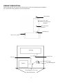
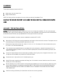
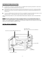
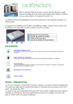
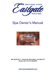
Ozone Systems
I nstallati o n & Owner's Man ual
UV-275
ClearWater Tech, LLC.
Integrated Ozone Systems
850-E Capitolio Way, San Luis Obispo, CA 93401 • 805-549-9724 • Fax: 805-549-0306 • E-mail: [email protected] • www.cwtozone.com
Copyright © 2009 - ClearWater Tech, LLC • Reproduction of any kind is prohibited • LIT81 • REV060311
IMPORTANT SAFETY INSTRUCTIONS
1.
PLEASE FOLLOW ALL INSTALLATION INSTRUCTIONS.
2.
Before attempting any electrical connections, be sure all power is off at the main
circuit breaker.
3.
The ultraviolet light produced by the UV-275 is harmful to your eyes and skin if
directly exposed. Do not look directly at the lamp. Always be sure power is off when
servicing.
4.
If remote mounting, Install the ozone generate at least five feet from the tub water
using non-metallic plumbing. Install the ozone generator no less than one foot above the
maximum water level to prevent water from contacting the electrical equipment.
5.
The electrical supply for this product must include a suitable rated switch or circuit breaker
to open all ungrounded supply conductors to comply with Section 42220 of the National
Electrical Code, ANSI / NFPA 70-1987. The disconnecting means must be readily
accessible to the occupant, but installed at least five feet from the tub water.
6.
This equipment must be v alidated by the manufactur e r for its intended use.
7.
SAVE THESE INSTRUCTIONS.
2
PRODUCT DESCRIPTION:
We recommend that you become familiar with the UV-275 unit by studying this illustration.
All components will be referred to by the names below.
Ozone Outlet
2.50” Dia.
Ozone Reaction
Chamber
UV Lamp View
Window
Bonding Lug
Power Cord
Air Pump
Check Valve
Air Line
UV Lamp
Lamp Retaining Nut
Ballast
Power Supply to UV Lamp
Mounting Brackets
3
PLUMBING:
There are two ways to plumb the UV-275:
1.
Using a tee in the air venturi line.
2.
Using a diffuser stone.
NOTE: All fittings, with the exception of a tee, will be provided by ClearWater Tech.
CAU TI ON: TH E O Z ON E D E LI V E R Y LI N E CA NN OT B E C OU P L E D T O A P R E S S U R I Z E D W AT E R
LI N E !
AIR LINE - TEE INSTALLATION:
N O T E : Use the following instructions if the venturi or air line of the spa is accessible. The air line is the upper
PVC pipe, flex or rigid, of the jet fittings. If the venturi line is not accessible, the instructions for the diffuser stone
should be followed. Consult your spa professional for the proper method on your spa.
For air line tee installation locations, see the installation schematic #T1 & #T2.
1.
Mount the UV-275 using the mounting brackets on the bottom of the electrical enclosure. The system can be
mounted using the mounting brackets or placed on it's nose.
2.
Determine the size of the venturi line, either 1/2", 3/4" or 1 1/2". Purchase a PVC tee the same size as your
line, with a 1/2" female threaded top.
3.
Turn the spa on high speed (blower not necessary). By having the spa on, water will evacuate this line. If
your selected plumbing location is in an area over the power pack, we recommend draining the spa. (see
caution on page 7)
4.
Cut the PVC pipe between the two lowest jets (if possible), this will give you the longest contact time. If the
low jets are not accessible, any location on this line will work.
5.
Cement the tee in place with the 1/2" threads opening up.
6.
Using Teflon tape, screw the provided tube fitting into 1/2" threads in the tee. Install one end of the ozone
delivery line on the tube fitting.
7.
Run the delivery line up from the tee to the highest point possible and cut the line here to install the check
valve. (See illustrations on installation schematic) NOTE: THE CHECK VALVE SHOULD BE MOUNTED
ABOVE THE WATER LINE. BE SURE THE FREE FLOW IS TOWARDS THE ELBOW OR AWAY FROM
THE OZONE UNIT.
8.
Continue running the delivery line back down and out to the ozone generator.
4
DIFFUSER STONE APPLICATION:
1.
A diffuser stone is supplied by ClearWater Tec h. This diffuser stone is specially produced for ozone and is
designed to give you years of service with very little care.
2.
Simply attach the open end of the tubing to the fitting at the bottom of the UV-275, and drop the diffuser
stone into the spa. When the ozonator is operating you should see tiny bubbles being dispersed from the
diffuser stone.
3.
The use of a diffuser stone will allow the UV-275 to be operated for longer periods without having to run the
equipment pack. It is the easiest and most convenient method for ozonating your spa.
NOTE: FOR OPTIMAL RESULTS, USE THE DIFFUSER STONE SIMULTANEOUSLY WITH THE FILTRATION
CYCLE.
N O T E : DIFFUSER STONES MAY BECOME CLOGGED AND RESULT IN AIR COMPRESSOR DAMAGE. TO
PREVENT THIS FROM HAPPENING, IT IS RECOMMENDED TO CLEAN YOUR DIFFUSER STONE ONCE A
MONTH. THIS CAN BE DONE BY SUBMERSING THE DIFFUSER STONE FOR A FEW HOURS IN A SOLUTION
MADE OF 50% WATER AND 50% MURIATIC ACID.
INSTALLATION SCHEMATIC:
Air Control Valve
(Must remain closed on air line installation)
Check Valve mounted ABOVE the water level
Location T1
Spa Air Line
Location T2
Location IM 2
Water Line
Location IM 1
Ozone Delivery Line
-5-
ELECTRICAL WIRING:
The optimum method is to have the ozone generator come on when the spa automatically comes on for filtration. In addition the
UV-275 has the abilit y to operate independently from all other functions due to the built-in air compressor. I f you are not familiar
with electrical circuitry, the installation should be done by a licensed electrician. All local codes must be observed.
There are several methods o f wiring the UV-275:
1. To a timer.
2. Directl y to the electrical panel.
3. To the low speed connection in the control box.
The UV-275 s ystems are available in 120 VAC, 1Ø, 60 HZ, 0.50 amperes or 220/240 VAC, 1Ø, 50/60 HZ, 0.30 amperes.
CAUTION: Be fore a tte mp ting any ele c tri c al hook -up, be sure the power is off a t th e m ain circuit box !
The UV-275 is intended to be wired using 18/3 water proof cord attached to the unit but can be hard wired using the
cord. To hard wire the s ystem: cut the plug o f f and strip back the exposed wires, run the black wire to position #1, #2
or #3 listed above. Run the neutral wire to a neutral terminal (protected by a GFCI). Then run the ground to a ground terminal.
BONDING REQUIREMENTS:
You must install a ground lead from the bonding lug (on the back o f the power pack) to the pool or spa's exterior ground line.
The line must be 6 AWG.
OPERATION
After the installation has been completed, the spa will operate as be fore. Again, for best results run the timer o f your
UV-275 simultaneously with the filtration c ycle.
NOTE: I f your UV-275 is installed to your air line, it is important to remember to keep the air dial(s) closed when not using the
spa.
The indicator light on the UV-275 will be on i f the unit is working, and you should smell a slight odor o f ozone from the spa.
RUNNING TIME:
For a spa that runs continuously, we recommend that the UV-275 s ystem be installed with a timer, a vailable from ClearWater
Tech. We suggest that the running time of the UV-275 start out with 4 hours. It is best to split this time up into two 2 hour
intervals, or four 1 hour intervals. We recommend that you start with longer periods and work your way down until y ou find the
optimum running time for your application.
Examples:
10-12 AM
10-12 PM
or
or
12-1 AM and 12-1 PM
6-7 AM and 6-7 PM
The bather load and frequency o f use will di f fer from owner to owner, there fore, you can adjust the time to fit your own
needs by increasing or decreasing the hours o f run time. NOTE: On commercial s ystems the filtration time will need
to be increased, please consult your dealer.
-6-
UNDERSTANDING YOUR WATER:
I f you are aware of a high concentration o f any mineral in your water (like calcium or iron), it is necessary to treat y our water
before starting the UV-275 s ystem. We suggest you take a sample of your water to a quali fied pool and spa dealer f or analysis.
They will make the proper recommendations o f product(s) needed to remove these minerals from your water. You should only
have to do this when you drain and fill new water into the spa.
I f your water is clean and clear, you can start the UV-275 s ystem right away. I f the water is dirt y or cloudy, we recommend that
you drain the water and thoroughly clean the filter(s) first.
CAUTION: I t is not re co m m ended tha t you drain an in-ground spa in the winter or a fter the firs t rain of the
s e a son. Ins te ad, you should use a shock tre a t m e nt bec aus e by draining you could possibly floa t the spa out
of the ground resulting in se v ere da m age.
OZONE AND BROMINE:
Ozone has a short hal f-li fe, or residual time, in your water. So there is a need to maintain a small residual o f another product in
the spa or pool. We recommend that you use Bromine. This Bromine residual will act as a buf fer when the ozone s ystem is not
operating. The bromine needs to be maintained at ONLY .8 ppm (parts per million), so that the trace amount o f product in the
water will not be noticed. Chlorine will work as a residual oxidizer, and ma y be used e f fecti vely in conjunction with the ozone
s ystem.
PREPARING YOUR WATER:
You should prepare your water by making the following adjustments and maintain these levels while using the UV-275 s ystem.
Bromine
or
Chlorine
pH
Total Alkalinit y
Calcium Hardness
1 to .8 ppm
1 to .5 ppm
7.2-7.6
80-150 ppm
180-250
Note: I f you experience any reaction with your water, such as coloring or unusual odor, please wait a few days to give the ozone
and filter s ystem time to work. I f the situation continues, consult your pool and spa dealer, possibly taking them a sample o f the
water.
SHOCK TREATMENT:
I f the water becomes cloudy with excessive oils or other contaminates, or a fter an unusually high bather load, we recommend
that you use a Non-chlorine shock treatment to assist the ozone in cleaning the water. These non-chlorine shock treatments are
available at your local pool or spa supply dealer, and are available under several di f ferent brand names, ask for assistance in
selecting the proper product.
FILTER CLEANING:
Ozone will keep your spa much cleaner than any other t ype o f spa or pool puri fication s ystem. The reason is that ozone
neutralizes body oils and soaps. A fter ozone kills the bacteria, the end product is ox ygen, carbon dioxide and filterable solids.
The filterable solids are usually at a higher level than with conventional sterilization processes, so your filter has a bit more work
to do. Keeping the filter clean will make a definite di f ference in the clarit y o f the water. Please set up a regular cleaning program,
or the end result will be poor flow when the low speed o f the pump comes on with the ozone s ystem. This will have a direct
ef fect on the amount o f ozone that will get into the water. An eas y check you can do without removing the filter is to look for air
bubbles through the jets (on air line installations) when the spa s ystem is on low speed (usually controlled by the timer). When
the filter is clean you will see many bubbles, when it is dirty you will hardly see any bubbles.
-7-
TROUBLE SHOOTING:
SITUATION: No indicator light
1. Check GFI to see if it has tripped.
2. Check lamp connection.
3. Check for blown lamp.
4. Check power supply
SITUATION: Ozone not present in water
1. Check for clean filter (a dirty filter will cause a low flow of ozone to spa).
2. Make sure air dial is closed on air line installations.
3. Make sure adjustable jets are all open and not loose.
4. Check for clogged jet (debris in line).
5. Check for kinked delivery line, blocked or reversed check valve.
6. Check diffuser stone to see that it has not been fouled.
SITUATION: Cloudy water with ozone present
1. Check pH balance.
2. Clean filter.
3. Check for other minerals in water.
4. Use a spa shock treatment to rid water of excess body oils.
5. Drain and clean spa and filter thoroughly.
SPECIFICATIONS UV-275:
Energy required: 120 VAC 0.5 AMPS or 220/240 VAC 0.3 AMPS
Rated up to: 500 gallon spa or 2000 gallon pool
Average lamp life: 9000 hours
Compressor rating: 6 PSI
Size: 7 x 5 x 10 Inches
Shipping Weight: 7 lbs.
8
ClearWater Tech, LL C L i mi t ed One-Year War ran ty
Summary of the Warranty
ClearWater Tech, LLC (“CWT”) makes every effort to assure that its products meet high quality and durability standards and warrants the products it manufactures
against defects in materials and workmanship for a period of one (1) year, commencing on the date of original shipment from CWT, with the following exceptions:
1) The warranty period shall begin on the installation date if the installation is performed within 90 days of the original shipment from CWT; 2) The warranty period
shall begin on the date of the bill of sale to the end user if the installation date is more 90 days after the original shipment date. To validate the warranty, a warranty
card, accompanied by a copy of the bill of sale, must be returned to CWT and must include the following information:
• End user name
• Complete address, including telephone number
• Date installed
• Complete model and serial number information
• Name of company from which the unit was purchased
Repairs and replacement parts provided under this warranty shall carry only the unexpired portion of this warranty or 90 days, whichever is longer.
Items Excluded from the Warranty
This warranty does not extend to any product and/or part from which the factory assigned serial number has been removed or which has been damaged or rendered
defective as a result of:
• an accident, misuse, alteration or abuse
• an act of God such as flood, earthquake, hurricane, lightning or other disaster resulting only from the forces of nature
• normal wear and tear
• operation outside the usage parameters stated in the product user’s manual
• check valve/solenoid valve failure
• use of parts not sold by CWT
• damage which may occur during shipping
• service or unit modification not authorized by CWT
• failure to meet service requirements as outlined in the I & O manual
Obtaining Service Under the Warranty
Any product and/or part not performing satisfactorily may be returned to CWT for evaluation. A Return Goods Authorization (RGA) number must first
be obtained by either calling or writing your local authorized dealer, distributor or CWT direct, prior to shipping the product. The problem experienced
with the product and/or part must be clearly described. The RGA number must appear prominently on the exterior of the shipped box(es). The product
and/or part must be packaged either in its original packing material or in comparable and suitable packing material, if the original is not available. You
are responsible for paying shipping charges to CWT and for any damages to the product and/or part that may occur during shipment. It is recommended
that you insure the shipment for the amount you originally paid for the product and/or part.
If, after the product and/or part is returned prepaid and evaluated by CWT, it proves to be defective while under warranty, CWT will, at its election,
either repair or replace the defective product and/or part and will return ship at lowest cost transportation prepaid to you except for shipments going
outside the 50 states of the United States of America. If upon inspection, it is determined that there is no defect or that the damage to the product
and/or part resulted from causes not within the scope of this limited warranty, then you must bear the cost of repair or replacement of damaged product
and/or part and all return freight charges. Any unauthorized attempt by the end user to repair CWT manufactured products without prior permission
shall void any and all warranties. For service, contact your authorized dealer or distributor or CWT direct at (805) 549-9724, extension 23.
Exclusive Warranty
There is no other expressed warranty on CWT products and/or parts. Neither this warranty, nor any other warranty, expressed or implied, including any
implied warranties or merchantability of fitness, shall extend beyond the warranty period. Some states do not allow limitations on how long an implied
warranty lasts, so that the above limitation or exclusion may not apply to you.
Disclaimer of Incidental and Consequential Damages
No responsibility is assumed for any incidental or consequential damages; this includes any damage to another product or products resulting from such a defect.
Some states do not allow the exclusion or limitation of incidental or consequential damages, so that above limitation or exclusion may not apply to you.
Legal Remedies of Purchaser
This warranty gives you specific legal rights and you may also have other rights which vary from state to state.
THIS STATEMENT OF WARRANTY SUPERSEDES ALL OTHERS PROVIDED TO YOU AT ANY PRIOR TIME.
C learWater Tech, L LC .
850 Capitolio Way, Suite E, San Luis Obispo, California 93401 • (805) 549-9724 • Fax: (805) 549-0306
9