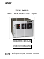
1
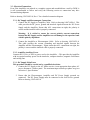
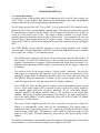
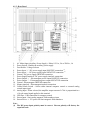
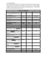
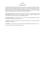
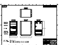
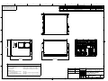
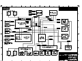
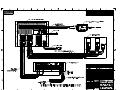
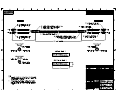
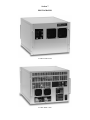
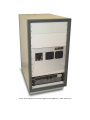
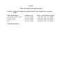
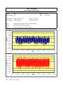
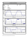
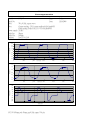
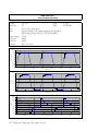
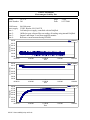
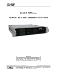
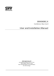
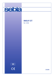
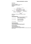
GM
MW
U
USER’S
S MAN
NUAL
M
MODEL
L: 231HC Biipolar Curreent Am
mplifierr
WARNING
The output from
f
the Model 231HC is pottentially lethal. Do not
operate withoout protective covvers and an insppection by an auuthorized
person.
PR
ROPRIETARY
THIS DOCUMEN
NT CONTAINS CON
NFIDENTIAL INFOR
RMATION PROPRIE
ETARY TO
GMW ASSOCIA
ATES. IT MUST NOT
N
BE REPROD
DUCED OR DISCLOSED TO
OTHERS OR USED IN ANY WAY EXCECPT FOR THE INSTA
ALLATION,
OPERATION OR
R MAINTENANCE OF
O GMW ASSOCIAT
TES PRODUCTS.
File No: 2331HC_Users_M
Manual_Rev_A
A
GM
MW
R
Revision
Date: 17 Decemberr, 2008
955
9 Industrial Road,
R
San Carrlos, CA 9407
70
Tel: (650)802-8292
E-mail:
E
sales@
@gmw.com Web:
W
http://www
w.gmw.com
F
Fax:
(650) 802
2-8298
TABLE OF CONTENTS
1 WARNINGS [ Refer to this section before operation ]
2.1 - Personal Safety
2.2 - Cable Connections
2.3 - Interlock Connections
Section 1
2
SPECIFICATIONS
Model 231HC General Specifications
Section 2
3
INSTALLATION
3.1 - Unpacking Instructions
3.2 - Rack Mounting
3.3 - Electrical Connections
Section 3
4 OPERATION
4.1 - System Description
4.1.1 - Front Panel
4.1.2 - Rear Panel
4.2 - Initial Operation
4.3 - External Control
4.4 - Computer Control
4.4.1 - USB 6251 DAQ
Section 4
5
Section 5
MAINTENANCE
6 DRAWINGS
231HC System in Bench Height Rack
General Assembly
Amplifier Block Diagram
System Connection Diagram
DC Supply to 231HC Amplifier
231HC Amplifier to Magnet Cable
Senis YM12 Signal & Power Cable
7
Section 6
11907-0046-0, Rev. B
11907-0068-0, Rev. C
13907-0002-1, Rev. C
13907-0003-0, Rev. C
16907-0030-0, Rev. A
16907-0031-0, Rev. A
16912-0000-0, Rev. A
PHOTOGRAPHS
231HC System in Bench Height Rack
8 231HC with GMW ELECTROMAGNETS
8.1 - Table - GMW Electromagnets and appropriate DC Power Supplies
8.2 - Performance Data
8.3 - Current and field noise measurements
Section 7
Section 8
Section 1
WARNINGS
REFER TO WARNINGS BELOW BEFORE OPERATING THE 231HC AMPLIFIER
2.1 - Personal Safety
Never service alone. Do not perform service to the 231HC and associated DC Power Supply
unless another person is present who is capable of rendering first aid.
The output from the model 231HC is potentially lethal. It is capable of delivering high voltages
at high current. Do not remove protective covers or leave cable terminations exposed. Do not
operate the amplifier if terminals or cables are damaged.
The 231HC Amplifier incorporates a capacitor bank of 0.2F capacitance to provide high peak
power. This capacitor bank and other internal components will remain charged for several
minutes even after the DC Power Supply is switched off.
Always disconnect the input dc power before servicing and ensure that sufficient time has passed
to completely discharge the capacitor bank before servicing the DC Power Supply, 231HC
Amplifier or its connected load. Always assume the presence of hazardous voltages. Always
connect a short insulated jumper cable across the dc input terminals before removing any
protective covers. Refer to Drawing 13907-0002-1.
2.2 - Current Connections
Special care should be taken to insure that the current terminations are secure and do not work
loose in operation. Local heating at the terminations can cause rapid oxidation leading to a high
contact resistance and high power dissipation at the terminals. If left unchecked this can cause
enough local heating to damage the current connection terminals.
2.3 - Interlocks
The 231HC Amplifier has interlock connections between the DC Power Supply and the
Electromagnet load. The interlocks must be connected for proper system functioning and
protection of the equipment, facility and to protect against personal injury. Attempting to
operate the system with the interlocks defeated is not recommended.
Section 2
SPECIFICATIONS
Table 1. Model 231HC Bipolar Current Amplifier Specifications
--------------------------------------------------------------------------------------------------------------------Electrical
Power Input (From DC Supply)
50V minimum to 160V maximum
Up to 1,000W required by the power amplifier
Recommended DC Power Supplies
Sorensen SGA 160/31 160V, 31A, 4,960W
Sorensen SGA 160/63 160V, 63A, 10,080W
Power Input for DC Power Supplies
Voltage
187 - 242VAC*
Current
SGA 160/31
21A
SGA 160/63
41A
200mF
20 x 10,000μF, 250VDC
Input Capacitor Bank
Power Input (Aux Power Supply)
Power Output
Control Modes
Computer Control
342-440VAC
396 - 528VAC
14A
13A
27A
26A
3 phase, 3 wire plus ground
* Standard delivery
115VAC, 50/60Hz, 2A
or 220VAC, 50/60hz, 1A
User selectable on rear panel
160V, 70A maximum
With SGA 160/31, approx. 3,960W average
With SGA 160/63, approx 9,080W average
National Instruments Multifunction DAQ, Model USB-6251
Current Control Resolution: 16 bits(1)
Current & Voltage Monitor Resolution:16 bits
Digital read back of amplifier and magnet interlock status
Magnetic field read back resolution:16 bits
Output Current Control(1)
Differential, ±10 volt analog input on rear panel
Input Impedance 50KΩ each input to ground, 25KΩ to each other
External Monitoring of Output Current & Voltage
Current Output:
±1V/10A, ±1%, Output Impedance 0.1Ω
Voltage Output:
±1V/20V, ±1%, Output Impedance 0.1Ω
Note (1): The Current output control may be via either the USB interface or the analog interface,
but not both.
Mechanical
231HC Amplifier
Form Factor
Overall Dimensions
Weight 47 kg (100 lbs)
8U rack mount fully enclosed chassis
482mm (19”) wide x 354mm (14”) high x 614mm (24.2”) deep
231HC Amplifier & SGA Power Supply in Optima Rack
Overall Dimensions
560.5 (22”) wide x 1,058 (41.6”) high x 823 (32.4”) deep
Weight (with Sorensen SGA 160/31)
135kg (300lbs)
Weight (with Sorensen SGA 160/63)
141kg (314lbs)
Section 3
INSTALLATION
Caution: The 231HC Amplifier’s mass is approximately 47 kg (100 lbs). In many cases, the
Amplifier will be pre-installed by GMW into a 19” EIA equipment rack. If it is not, care should
be taken during rack mounting to avoid personal injury or damage to the equipment.
3.1 - Unpacking Instructions and Damage Inspection
3.1.1 - Systems Shipped with a GMW Supplied Rack:
1. Remove all eight of the lag bolts located at the lower edge of all the side panels of the
crate top cover.
2. Gently rock the crate top cover to work it loose from the shipping crate base.
3. Use one person on each side of the shipping crate grip the side panels of the crate top
cover. Lift the crate top cover high enough to clear top of the rack, walk the cover
sideways to a clear area and place it upon the floor.
4. Inspect the rack and its contents to ensure that no damage has occurred during
shipment. If any damage is evident report the damage in detail to the shipper for
claim and simultaneously notify GMW in case an assessment of the damage must be
made. If no damage is found, proceed with the unpacking and installation.
5. Cut the straps that secure the rack to the pallet base.
6. Remove the wood block at the bottom front edge of the rack.
7. Carefully slide the rack forward and off of the pallet base.
8. Unpack any other system components as per their instruction manuals.
3.1.2 - Systems Shipped without a GMW Supplied Rack:
1. Open the shipping crate by removing the spring clips along the crate top panel.
2. Cut the straps that secure the amplifier into the shipping crate.
3. Using two people, carefully lift the amplifier clear of the shipping crate. Handles
have been provided on the front as well as the rear of the amplifier case for this.
Always lift the amplifier by all four handles.
4. Inspect the amplifier to ensure that no damage has occurred during shipment. If any
damage is evident report the damage in detail to the shipper for claim and
simultaneously notify GMW in case assessment of the damage must be made. If no
damage is found, proceed with the installation.
5. Unpack any other system components as per their instruction manuals.
3.2 - Rack Mounting
When rack mounting the 231HC Amplifier it is important to note that the vertical mounting
flanges alone are not strong enough to support the weight of the amplifier, and support angles on
each side, beneath the 231HC, must also be used. Failure to use adequate support angles will
result in equipment damage.
Take care when selecting a rack that it has enough depth to completely house the Amplifier and
DC Supply. The RC-351930 Bench Height Rack offered by GMW has an internal depth of
762mm. Typical installations would put the DC Supply at the bottom of the rack, with the
Amplifier just above, thus keeping the center of gravity as low as possible in the rack. Other
instrumentation may then be installed in to the upper sections of the rack.
Note: Telco style racks are NOT appropriate for the Amplifier and DC Supply.
3.3 - Electrical Connections
Even if the Amplifier was ordered as a complete system and assembled into a rack by GMW, it
is still recommended to follow and verify the following section as connections may have
loosened during shipment.
Refer to drawing 13907-0003-0, Rev. C for a detailed connection diagram.
3.3.1 - DC Supply and Electromagnet Connections
1. Connect the DC Supply to Amplifier Cable. Refer to drawing 16907-0030-0. This
cable provides the DC power, ground and interlock signals between the DC Power
Supply and the Amplifier. Ensure that ALL connections are tight, the polarity is
correct and the interlock cable is properly connected.
Warning: It is critical to ensure the correct polarity current connections
between the DC Supply and the Amplifier to avoid damage to the capacitor bank
which is polarity dependent.
2. Connect the Amplifier to Electromagnet Cable. Refer to drawing 16907-0031-0.
This cable provides the current, grounding and interlock signals between the
Amplifier and the Electromagnet. Again ensure that ALL connections are tight, the
polarity is correct and the interlock cable is properly connected.
3.3.2 - Amplifier Auxiliary Power
Connect the 115Vac or 220Vac power cord to the Amplifier. - This provides the Amplifier
with its required auxiliary power for the interlocks, computer interface, magnetic field sensor
and cooling fans.
3.3.1 - DC Supply Main Power
This procedure should be carried out by a qualified electrician.
1. Connect the DC Supply to the AC Mains service via an appropriate three-phase AC
power disconnect / breaker panel. The maximum input currents per phase are given
in Section 1, Specifications.
2. Ensure that the Electromagnet, Amplifier and DC Power Supply grounds are
connected. The DC Power Supply must be connected to the local service ground.
Refer to drawing 13907-0003-0.
Section 4
SYSTEM DESCRIPTION
4.1 - System Description
A complete system would typically consist of an appropriate SGA series DC power supply, the
GMW 231HC, a Senis magnetic field transducer, an electromagnet and finally an appropriate
computer and software or an external analog programming signal.
The DC Supply provides the 160V, 31A (or 160V, 63A) dc power to the 231HC Amplifier and is
buffered by the 231HC’s internal 200mF capacitor bank. The capacitor bank provides current
for short duration overloads of the DC Supply. The DC Supply is interlocked to the 231HC by
means of a relay contact in the 231HC. The Supply’s output is enabled on a closed contact,
providing protection should the interlock cable be disconnected. Two conditions will cause the
interlock relay to open, shutting down the DC Supply’s output: Failure in the auxiliary power
supply in the 231HC or a failure in the temperature or water flow interlocks on the electromagnet
load.
The 231HC Bipolar Current Amplifier integrates a Copley 231HC Amplifier with a 200mF
capacitor bank, a National Instruments USB-6251 Control with USB interface and an auxiliary
power supply into a single 19” rack mounting chassis.
The auxiliary power supply provides power for the cooling fans, interlocks and interface. It
also provides -12V and +12V (400mA each) on the rear panel for an optional external Senis
magnetic field transducer for magnetic field measurement and closed-loop field control. It is
important to note that if the auxiliary supply is not powered up, the DC Supply’s output will
be inhibited.
The interlock circuit for the magnet requires a ‘closed contact’ connection. Provision for
both magnet over temperature and water flow is provided, but they are connected in series
and simply ‘Magnet Fault’ is indicated on the status panel of the 231HC and when using the
NI USB-6251 DAQ, this information is available via the computer control software. In the
event of a magnet interlock fault, the output of the DC Supply is inhibited.
The NI USB-6251 DAQ interface provides computer control and monitoring of the system.
It uses a 16-bit analog output (±10V) to provide the drive signal to the Copley Amplifier.
The amplifier output voltage and current are monitored by two 16-bit input channels.
Complete amplifier and magnet interlock status is also monitored via its digital input
channels. When using an optional Senis magnetic field transducer, the field is read back on a
third 16-bit analog channel. For more information, please refer to the NI USB-6251 Manual
and section 4.5 in this manual.
The Copley 231HC Amplifier provides the power conversion from the fixed voltage DC
Supply to a programmable current source for the electromagnet. The current output is
proportional to the programming input of ±10V, supplied by either the NI USB-6251 or the
external analog voltage input. The amplifier is set by GMW to a full scale range of ±70A
output for ±10V input. For more information, please refer to the Copley Controls 231HC
Manual.
The optional Senis magnetic field transducer provides magnetic field monitoring for closed-loop
control feedback. It is powered by the auxiliary power supply in the 231HC.
4.1.1 - Front Panel
1.
2.
3.
4.
5.
6.
7.
8.
9.
10.
11.
12.
13.
Auxiliary Power - Indicates that auxiliary power is present
Magnet Interlock Fault - Indicates a fault with the magnet temperature or water flow
interlocks
Amplifier Power - Indicates when DC power is provided to the 231HC
Amplifier Ready - Indicates either ‘Ready’ (Green) or ‘Fault’ (Red)
DC Fault - Indicates when DC power is outside the normal operating limits
Over Current - Indicates that the output is disabled due to over current over limits
Over Temperature - Indicates the 231HC is disabled due to an over temperature
condition
Output Enabled - Illuminates when the 231HC output is enabled
Module Fault - Indicates the 231HC is disabled due to a fault in the amplifier’s
MOSFET power output module
Voltage Monitor Output - ±1V / 20V, 1%
Current Monitor Output - ±1V / 10A, 1%
Output Inhibit Control - Inhibits the output of the 231HC
Reset Control - Resets fault conditions
4.1.2 - Rear Panel
1.
2.
3.
4.
5.
6.
7.
8.
9.
10.
11.
12.
13.
14.
15.
16.
AC Mains Input (Auxiliary Power Supply) - Either 115Vac, 2A or 220Vac, 1A
Power Switch - Enables the auxiliary power supply
Fuse Holder / Voltage Selector
Power Input ‘+’ - DC power supply input POSITIVE connection (1)
Power Input ‘-‘ - DC power supply input NEGATIVE connection (1)
Ground - DC power supply GROUND connection
Power Supply Interlock - DC power supply interlock connection
Power Output ‘+’ - Electromagnet power output POSITIVE connection
Power Output ‘-’ - Electromagnet power output NEGATIVE connection
Ground - Electromagnet GROUND connection
Magnet interlock - Electromagnet interlock connection
Control Mode Switch - Selects either internal computer control or external analog
control input signal.
Analog Input - When selected, the amplifier output current of ±70A is proportional to a
±10 volt control signal applied to this terminal
USB Port - USB connection for computer control
Sensor Input - Senis analog magnetic field transducer input
Sensor Power - ± 12V power for Senis magnetic field transducer
Note:
(1) The DC power input polarity must be correct. Reverse polarity will destroy the
capacitor bank
4.2 - Initial Operational Testing
Once the 231HC system is connected it is time to perform initial system operational checks.
Start by switching on the auxiliary power supply in the 231HC. The switch is in the power entry
module at the rear of the unit. At this point the ‘Auxiliary Power’ LED in the status panel
should illuminate. The ‘Magnet Fault’ LED should be off, if it is not check that the magnet
interlocks are correctly connected and functioning.
If a system complete with computer and software was purchased, the Amplifier Control and
Monitoring software should be started now. Please refer to the software manual for
configuration details.
The next step is to provide DC power the 231HC. Ensure that the voltage and current controls of
the SGA DC Power Supply are set to the minimum output before turning on the main power to
the DC Supply. Turn on the DC Supply and set the current output control to about 5% (about 3
turns clockwise). Next slowly bring up the Voltage control. At about 20 volts, the ‘Amplifier
Power’, ‘Amplifier Ready’ (red aspect) and the ‘DC Fault’ LEDs on the status panel of the
231HC will illuminate. After about 35 volts, the status panel LEDs should change to ‘Amplifier
Power’, ‘Amplifier Ready (green aspect) and ‘Output Enabled’.
Please refer to the Copley Controls manual for the 231HC Amplifier for more information if
needed.
4.3 - External Control
To use the external control option, set the ‘Control Mode’ switch on the rear panel to ‘External’.
This disconnects the internal DAC and connects the Analog Input terminal to the amplifier
analog control input. One thing to note is that it is still possible to use the internal DaqPAD for
monitoring the 231HC even when using an external analog control signal.
Connect an analog voltage source to the Analog Input terminal. This source should be capable
of delivering voltages from -10V to +10V. The amplifier current output is proportional to the
analog control input voltage.
Take care not to exceed an instantaneous dc power dissipation in the electromagnet in excess of
4,160W when using the SGA 160/31 power supply, or 9,280W when using the SGA 160/63
power supply. If this is exceeded, the amplifier may enter a mode that draws more power than
the DC supply can provide and the DC power supply will shut down. When the DC supply
voltage drops, the amplifier enters a ‘DC Fault’ mode and shuts down. Once shut down, the DC
supply will recover, then the amplifier recovers, restarts and the cycle repeats. The only way to
break the cycle is to reduce analog control signal to zero.
4.4 - Computer Control
To use the external control option, set the ‘Control Mode’ switch on the rear panel to ‘Internal’.
This connects the internal DAC and disconnects the Analog Input terminal to the amplifier
analog control input.
Start up the computer software and ensure that everything configured correctly. Please refer to
the software manual for more information.
4.4.1 - USB-6251 DAQ
The National Instruments USB-6251 DAQ together with GMW’s Magnet Control software
provides control and monitoring of the 231HC Bipolar Amplifier. If GMW’s Magnet
Control software is not used, it is still possible to computer control the 231HC Bipolar
Amplifier by writing custom software to communicate with the USB-6251. The table below
describes the channels used and their functions.
Signal
USB-6251 Connections
Type
Direction
Current Control Output
±10V output proportional to ±70A
current output
Current Control Common
Current Monitor
±1V / 10A
Current Monitor Common
Voltage Monitor
±1V / 20V
Voltage Monitor Common
Field Monitor +
Field Monitor Field Monitor Common
+5V (Amplifier Power) - Active high,
the 231HC DC supply is providing
sufficient voltage for operation
Normal - Active low, the 231HC is
ready and will operate when not
inhibited
Inhibit - Active low, the front panel
inhibit switch is active
Module Fault - Active low, the
231HC has a fault in the MOSFET
power output module
DC Fault - Active low, one or more
DC voltages are outside operating
limits
Over Current - Active low, the
231HC is disabled due to current over
limits
Over Temperature - Active low, the
231HC is disabled due to an over
temperature condition
231HC Digital Ground
Interlock Status Interlock Status Common
6251 Terminal
Analog
Output
AO-0
Ground
Analog
Ground
Input
AO-GND
AI-1
Analog
Analog
Input
Input
AI-9
AI-0
Analog
Analog
Analog
Ground
Input
Input
Input
Ground
AI-8
AI-2
AI-10
AI-GND
Digital
Input
P0.0
Digital
Input
P0.1
Digital
Input
P0.2
Digital
Input
P0.3
Digital
Input
P0.4
Digital
Input
P0.5
Digital
Input
P0.6
Ground
Digital
Ground
Ground
Input
Ground
DGND
P0.7
DGND
Section 5
MAINTENANCE
The 231HC Bipolar Amplifier should operate for many years without any trouble provided that
the following basic maintenance points are observed. Always remember that the ac power
should be disconnected before performing any maintenance procedure. The 231HC generates
lethal voltages and must not be operated with damaged components, protective covers or cable
insulation. For more information, please refer to Section 2, Warnings
1. Electrical Connections: Ensure that all electrical connections are clean and tight. Ensure that
the insulation of all electrical cables is undamaged and repair or replace if necessary. All
electrical termination covers must be in place and firmly secured.
2. Warning Labels: Ensure that all protective covers on the system and the magnet are in place.
There are warning labels on all removable covers.
3. Cooling: Check that the fan screens are clean and free of blockage. Ensure that the fans are
operating at full efficiency.
4. Cleaning: To clean wipe the case with a soft cloth with a mild detergent or plain water. Do
not use any solvents as they may damage the finish.
Section 6
DRAWINGS
8
7
6
4
5
PROPRIETARY
3
ZONE
THIS DRAWING CONTAINS CONFIDENTIAL
INFORMATION PROPRIETARY TO GMW INC. IT MUST
NOT BE REPRODUCED OR DISCLOSED TO OTHERS OR
USED IN ANY OTHER WAY, IN WHOLE OR IN PART
EXCEPT AS AUTHORIZED IN WRITING BY GMW INC.
REV
A
B
C
2
REVISION HISTORY
DESCRIPTION
Release
Add Power Requirements Block
Update Service Panel
1
DATE
5 Sep, 06
20 Dec, 06
22 May, 08
APPROVED
Michael E. Duffy
Michael E. Duffy
Michael E. Duffy
F
F
E
E
D
D
C
354 [14"]
C
482 [19"]
B
626 [24.6"]
B
Power Requirements
Auxiliary AC Power:
Power One HAD12-0.4-A
Power One HB12-1.7-A
Cosel P15E-12
A
120VAC @ 0.4A / 240VAC @ 0.2A, 50/60Hz
120VAC @ 0.6A / 240VAC @ 0.3A, 50/60Hz
120VAC @ 0.3A / 240VAC @ 0.15A, 50/60Hz
Amplifier DC Power:
Sorenson / Elgar SGA160/31C Output:
AC Power Requirement:
Sorenson / Elgar SGA160/63C Output:
AC Power Requirement:
DRAWN
19 Dec, 06
Date
ENGINEERING
160V, 31A
187-242VAC, 3 Phase, 25A per phase 50/60Hz
160V, 63A
187-242VAC, 3 Phase, 41A per phase 50/60Hz
DO NOT SCALE
FROM DRAWING
Date
M. Duffy
CHECK
M. Duffy
M. Duffy
DIMENSIONS & TOLERANCES
UNLESS OTHERWISE SPECIFIED
19 Dec, 06
LINEAR
Date
X.XXX
19 Dec, 06
X.XX
INCHES
mm
±.005
±0.03
± .01
± 0.1
X.X
±.03
±0.3
X
±.06
±1
DEG.
±.5
±0.5
FINISH
63
1.6
THIRD ANGLE PROJECTION
GMW Associates
955 Industrial Road, San Carlos, CA 94070
Tel: (650) 802-8292. Fax: (650) 802-8298
231HC Bipolar Amplifier
General Assembly
SIZE
DRAWING No.
7
6
5
4
3
2
REV
A2 11907-0068-0
SCALE: NTS
8
A
TITLE
WT: -
kg
C
SHEET: 1
1
OF: 1
Section 7
PHOTOGRAPHS
231HC Front View
231HC Rear View
231HC & Sorenson SGA Power Supply in an Optima 19” Rack front view
Optima Rack rear view
Section 8
231HC with GMW ELECTROMAGNETS
8.1 Table - GMW Electromagnets and appropriate DC Power Supplies for use with the
231HC
GMW Electromagnet
Peak DC Power
Xantrex - Sorenson Power Supply
5403, 5403EG, 5403FC, 5403AC
3472-50, 3472-70
3473-50, 3473-70
5451
70A, 33V, 2,500W
70A, 50V, 3,500W
70A, 59V, 4,100W
70A, 25V, 1,800W
SGA 160/31, 160V, 31A, 4,960W
SGA 160/31, 160V, 31A, 4,960W
SGA 160/63, 160V, 63A, 10,080W
SGA160/31, 160V, 31A, 4,960W
8.2 Performance Data
GMW Associates
Electromagnet Stability Plot
Model:
5403
Serial Number: 246
Engr:
Date:
Field Sencor: Senis YM12-3-2-2T
Power supply: 231HC, Bipolar
Note 1:
Note 2:
Note 3:
Y.Qin
12/14/2006
Pole Gap: 30mm
Pole Face:38mm
50Hz low pass software filter on field reading
Field mode (closed loop control)
Field measured at the center of gap.
1.10010
1.10008
1.10006
Field (T)
1.10004
1.10002
1.10000
1.09998
1.09996
1.09994
1.09992
1.09990
13:05:00
13:15:00
13:25:00
13:35:00
Time
13:45:00
13:55:00
14:05:00
13:35:00
Time
13:45:00
13:55:00
14:05:00
45.10000
Current (A)
45.00000
44.90000
44.80000
44.70000
44.60000
44.50000
13:05:00
13:15:00
1Hr stability field mode.xls
13:25:00
GMW Associates
Electromagnet Stability Plot
Model:
5403
Serial Number: 246
Engr:
Date:
Field Sencor: Senis YM12-3-2-2T
Power supply: 231HC, Bipolar
Note 1:
Note 2:
Note 3:
Y.Qin
12/14/2006
Pole Gap: 30mm
Pole Face:38mm
50Hz low pass software filter on field reading
Field mode (closed loop control)
Field measured at the center of gap.
1.10010
1.10008
1.10006
Field (T)
1.10004
1.10002
1.10000
1.09998
1.09996
1.09994
1.09992
1.09990
13:00:20
13:00:25
13:00:30
13:00:35
13:00:40
Time
13:00:45
13:00:50
13:00:55
13:01:00
13:00:40
Time
13:00:45
13:00:50
13:00:55
13:01:00
45.00000
44.90000
Current (A)
44.80000
44.70000
44.60000
44.50000
44.40000
44.30000
44.20000
13:00:20
13:00:25
60sec stability field mode.xls
13:00:30
13:00:35
GMW Associates
Electromagnet waveform
5403
Engr:
246
Date:
50A, 0.5Hz, square wave
Current reading: 231P current readback+NI USB-6251
Field reading: Senis YM12-3-2-2T+NI USB-6251
Power supply: 231HC
30mm
Pole Gap:
38mm
Pole Face:
X=0, Y=0, Z=0
Position:
Model:
Serial No:
Note:
Note:
Y. Qin
12/20/2006
60
Current (A)
40
20
0
-20
-40
-60
0
1000
2000
3000Time (ms) 4000
5000
6000
7000
8000
0
1000
2000
3000 Time (ms) 4000
5000
6000
7000
8000
0
1000
2000
3000 Time (ms)4000
5000
6000
7000
8000
1.5
Field (T)
1.0
0.5
0.0
-0.5
-1.0
-1.5
200
150
Voutput (V)
100
50
0
-50
-100
-150
-200
5403 30mm gap, 38mm pole 50A 0.5Hz square.xls
GMW ASSOCIATES
Electromagnet: Typical Waveform
Model:
Serial No:
Pole Face:
Pole gap:
5403AC
1
10mm
10mm
Engr:
Date:
Page:
Power Supply:
PS SN:
Position:
Current:
Waveform:
231HC
2606FD05
X=Y=Z=0mm
60A peak to peak
1Hz, square
Y.Q.
1/26/2007
1 of 1
Current (A)
80
60
40
20
0
-20
-40
-60
-80
0
0.2
0.4
0.6
0.8
1
Time(second)
1.2
1.4
1.6
1.8
2
0
0.2
0.4
0.6
0.8
1
Time(second)
1.2
1.4
1.6
1.8
2
1.2
1.4
1.6
1.8
2
3
Bz (T)
2
1
0
-1
-2
-3
Magnet Voltage(V)
200
150
100
50
0
-50
-100
-150
-200
`
0
0.2
0.4
0.6
0.8
1
Time(second)
5403AC 10mm pole 10mmgap 1Hz 60A square waveform .xls
GMW Associates
Electromagnet waveform
Model:
Serial No:
Note:
Note:
3472-70
Engr:
Date:
Y. Qin
12/18/2006
70A, 0.5Hz, square wave
Current reading: 231P current readback+DAQpad6015
Field reading: Senis YM12-3-5-5T+DAQPad6015
Power supply: 231HC
50mm
Pole Gap:
100mm
Pole Face:
X=0, Y=0, Z=0
Position:
80
60
Current (A)
40
20
0
-20
-40
-60
-80
0
1000
2000
Time (ms) 3000
4000
5000
6000
0
1000
2000
Time (ms) 3000
4000
5000
6000
0
1000
2000
Time (ms) 3000
4000
5000
6000
1.5
Field (T)
1.0
0.5
0.0
-0.5
-1.0
-1.5
200
150
Voutput (V)
100
50
0
-50
-100
-150
-200
3472-70 100mm pole 50mm gap 0.5Hz square 70A.xls
GMW Associates
Electromagnet waveform
Model:
Serial No:
Note:
Note:
Power supply:
Pole Gap:
Pole Face:
Position:
3473-70
Y. Qin
Engr:
116
10/19/2006
Date:
60A, 0.2Hz, square wave
Current reading: 231P current readback+DAQpad6015
Field reading: Senis YM12-3-5-5T+DAQPad6015
231HC
10mm
75mm
X=0, Y=0, Z=0
80
60
Current (A)
40
20
0
-20
-40
-60
-80
0
2000
4000
6000 Time (ms) 8000
10000
12000
14000
0
2000
4000
6000 Time (ms) 8000
10000
12000
14000
0
2000
4000
6000 Time (ms) 8000
10000
12000
14000
3.0
Field (T)
2.0
1.0
0.0
-1.0
-2.0
-3.0
200
150
Voutput(V)
100
50
0
-50
-100
-150
-200
3473 75mm pole 10mm gap 0.2Hz square 60A.xls
GMW Associates
Electromagnet Stability Plot
Model:
3473-70
Serial Number: 246
Field Sencor:
Power supply:
Note 1:
Note 2:
Note 3:
Note 4:
Engr:
Date:
Y.Qin
10/17/2008
No field sensor
231HC, Bipolar, SN:134A7CE
Cold start power supply, controlled with int DAQPad
100Hz low pass software filter on reading, all reading using internal DAQPad
Output I and Output V read from amplifier monitor
Reference current measured using DF860R.
Output I
60.20
Current (A)
60.15
60.10
60.05
60.00
59.95
59.90
10:00:00
10:30:00
11:00:00
Time
11:30:00
12:00:00
DF 860R
60.20
Current (A)
60.15
60.10
60.05
60.00
59.95
Voltage (V)
59.90
10:00:00
48.00
47.50
47.00
46.50
46.00
45.50
45.00
44.50
10:00:00
10:30:00
11:00:00
Time
11:30:00
12:00:00
Output V
10:30:00
231HC 1 hour stability int Ip unit 2.xls
11:00:00
Time
11:30:00
12:00:00
GMW Associates
Electromagnet Stability Plot
Model:
3473-70
Serial Number 246
Engr:
Date:
Y.Qin
10/17/2008
Current (A)
Field Sencor: No field sensor
Power supply: 231HC, Bipolar, SN:134A7CE
Note 1:
Cold start power supply, controlled with ext power supply, HP E3620A.
Note 2:
100Hz low pass software filter on reading, all reading using internal DAQPad
Note 3:
Output I and Output V read from amplifier monitor
Note 4:
Reference current measured using DF860R. Ip is program voltage
60.15
60.10
60.05
60.00
59.95
59.90
59.85
59.80
59.75
13:00:00.
Output I
13:30:00.
14:00:00.
14:30:00.
15:00:00.
Current (A)
Time
60.15
60.10
60.05
60.00
59.95
59.90
59.85
59.80
59.75
13:00:00.
DF 860R
Ip
13:30:00.
14:00:00.
14:30:00.
15:00:00.
Time
Output V
Voltage (V)
47.60
47.40
47.20
47.00
46.80
46.60
13:00:00.
13:30:00.
14:00:00.
Time
231HC 1 hour stability ext Ip unit 2.xls
14:30:00.
15:00:00.