1
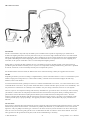
Strong Light Control Systems TM Installation, Setup, and Operation Manual (Covers LCS, CLD, AD, LDP, and AP Models) Cinema Products Revision 1.04 May 2009 Strong Light Control Systems Installation, Setup, and Operation Manual PR011 Revision 1.04 This manual describes the installation, setup and operation of the LCS, AD, CLD, LDP, and AP Dimmer and auxiliary cabinets. Optional CineNet and related equipment is covered in the following product reference manuals: ! ! ! ! ! ! ! ! ! ! ! ! ! ! ! ! ! ! ! ! PR001 CNA Installation Manual PR002 CNA-200 Setup and Operation Manual PR003 CNA-150 Setup and Operation Manual PR004 CNA-100 Setup and Operation Manual PR005 QDC-400 Setup and Operation Manual PR006 ACP-50 Installation and Setup Manual PR007 RVC-5 Installation and Setup Manual PR008 PCI-64 Gateway Interface Installation PR009 CineNet Host Software PR010 RCM-10/RSM-10/RSM-20 Installation and Operation Manual PR011 Strong Dimmer Installation, Setup, and Operation Manual PR012 eCNA-100 Automation Manual PR013 eCNA-150 Automation Manual PR014 eCNA-200 Automation Manual PR016 Strong FP350 Installation and Operation Manual PR017 Eprad FP350 Installation and Operation Manual PR018 Paging system Setup and Installation Manual PR019 VNC Setup and Operation Manual PR020 CineSuite Installation and Operation Manual PR021 eCNA-10 Automation Manual W arranty CineNet automation products, sold by STRONG INTERNATIONAL, are warranted against defects in materials and workmanship for one year from the date of purchase. There are no other express or implied warranties and no warranty of merchantability or fitness for a particular purpose. During the warranty period, STRONG INTERNATIONAL will repair or, at its option, replace components that prove to be defective, provided the unit is shipped prepaid to the manufacturer directly or via an authorized distributor. Not covered by this warranty are defects caused by modification, misuse or accidents and any further damage caused by inadequate packing for service return. STRONG INTERNATIONAL's obligation is restricted to the repair or replacement of defective parts and under no circumstances will STRONG INTERNATIONAL be liable for any other damage, either direct or consequential. Information in this document is subject to change without notice. No part of this document may be reproduced or transmitted in any form or by any means, electronic or mechanical, for any purpose, without the express written permission of STRONG INTERNATIONAL. © 1997 - 2009 STRONG INTERNATIONAL. All rights reserved. Table of Contents: Introduction . . . . . . . . . . . . . . . . . . . . . . . . . . . . . . . . . . . . . . . . . . . . . . . . . . . . . . . . . . . . . . . . . . . . . . . . . . . . . . . -1System components . . . . . . . . . . . . . . . . . . . . . . . . . . . . . . . . . . . . . . . . . . . . . . . . . . . . . . . . . . . . . . . . . . -1Installation . . . . . . . . . . . . . . . . . . . . . . . . . Installation Guidelines . . . . . . . . . Dimmer Cabinet Mounting . . . . . dimensions . . . . . . . . . . . . . . . . . . W iring Methods . . . . . . . . . . . . . . Parallel 2K W att Power Modules . . . . . . . . . . . . . .. .. .. .. .. .. . . . . . . . . . . . . .. .. .. .. .. .. . . . . . . . . . . . . .. .. .. .. .. .. QDC-400 based Dimmers and Auxiliary Cabinets . . . . . . . QDC-400 Dimmer Controller . . . . . . . . . . . . . . . The QDC and luminescence . . . . . . . . . . . . . . . . . QDC Operation in the LCS System. . . . . . . . . . . . Bypass Jumpers and Channel Override Switches . Status LED . . . . . . . . . . . . . . . . . . . . . . . . . . . . . . Switch Configuration . . . . . . . . . . . . . . . . . . . . . . Switch Definitions . . . . . . . . . . . . . . . . . . . . . . . . Multiple QDC-400 Control Boards . . . . . . . . . . . The 37811-B Input Board . . . . . . . . . . . . . . . . . . Transformer Wiring . . . . . . . . . . . . . . . . . . . . . . The 37870 2K W att Dimmer Module . . . . . . . . . 37811-A Control PCB . . . . . . . . . . . . . . . . . . . . . . . . . . . . . . . . . .. .. .. .. .. .. . . . . . . .. .. .. .. .. .. . . . . . . .. .. .. .. .. .. . . . . . . .. .. .. .. .. .. . . . . . . .. .. .. .. .. .. . . . . . . .. .. .. .. .. .. Setup . . . . . . . . . . . . . . . . . . . . . . . . . . . . . . . . . . . . . . . 37627 Analog Control Card, Basic Setup . . . Configuration . . . . . . . . . . . . . . . . . . . . . . . . . Adjustment Potentiometers . . . . . . . . . . . . . . The AP Expansion Cabinet . . . . . . . . . . . . . . . . . . . . . . . . . . . . . . .... .... .... .... .... Addendum . . . . . . . . . . . . . . . . . . . . . . . . . . . . . . . . . . . . . . Troubleshooting . . . . . . . . . . . . . . . . . . . . . . . . . . . QDC-400 Software Changes and Revision History BootLoader Changes: . . . . . . . . . . . . . . . . . . . . . . . . . . . . . . . . . . . . . . . . . . . . . . . . . . . . . . . . . . . . . . . . . . . . . . . . . . . . . . . . . . . . . . . . . . . . . . . . . . . .... .... .... .... .... .... .... .... .... .... .... .... .... . . . . . . . . . . . . .. .. .. .. .. .. . . . . . . . . . . . . . . . . .... .... .... .... .... .... .... .... .... .... .... .... .... . . . . . . . . . . . . .. .. .. .. .. .. . . . . . . . . . . . . . . . . .... .... .... .... .... .... .... .... .... .... .... .... .... . . . . . . . . . . . . .. .. .. .. .. .. . . . . . . . . . . . . . . . . .... .... .... .... .... .... .... .... .... .... .... .... .... . . . . . . . . . . . . .. .. .. .. .. .. . . . . . . . . . . . . . . . . .... .... .... .... .... .... .... .... .... .... .... .... .... . . . . . . . . . . . . . . . . . . -2-2-3-5-5-7- AD System operation . . . . . . . . . . . . . . . . . . . . . 37627 Analog Dimmer Controller . . . . 37627 Operation . . . . . . . . . . . . . . . . . The 37670 2K W att Dimmer Module . . . . . .... .... .... .... .... .... .... .... .... .... .... .... .... . . . . . . -21-22-23-23-24-24-25-25-25-27-28-29-30-30- . . . . .... .... .... .... .... .... .... .... .... .... .... .... .... . . . . . . LCS Dimmer Setup . . . . . . . . . . . . . . . . . . . . . . . . . . . . . . . . . . . . . . . . . . . . . . . . . . . . . . . . . . . . . . . . . . . . . . . . Menu Structure . . . . . . . . . . . . . . . . . . . . . . . . . . . . . . . . . . . . . . . . . . . . . . . . . . . . . . . . . . . . . . . . . . . . . Manual Control . . . . . . . . . . . . . . . . . . . . . . . . . . . . . . . . . . . . . . . . . . . . . . . . . . . . . . . . . . . . . . . . . . . . Using the LCS-2K/4K Dimmer with the CNA . . . . . . . . . . . . . . . . . . . . . . . . . . . . . . . . . . . . . . . . . . . . . eCNA-150 Dimmer Setup . . . . . . . . . . . . . . . . . . . . . . . . . . . . . . . . . . . . . . . . . . . . . . . . . . . . . . . . . . . . CNA-150 Dimmer Setup . . . . . . . . . . . . . . . . . . . . . . . . . . . . . . . . . . . . . . . . . . . . . . . . . . . . . . . . . . . . . CNA-100/150 soft overrides and program . . . . . . . . . . . . . . . . . . . . . . . . . . . . . . . . . . . . . . . . . . . . . . . . eCNA-200 Dimmer Set-up . . . . . . . . . . . . . . . . . . . . . . . . . . . . . . . . . . . . . . . . . . . . . . . . . . . . . . . . . . . CNA-200 Dimmer Set-up . . . . . . . . . . . . . . . . . . . . . . . . . . . . . . . . . . . . . . . . . . . . . . . . . . . . . . . . . . . . CNA-200 soft overrides and program . . . . . . . . . . . . . . . . . . . . . . . . . . . . . . . . . . . . . . . . . . . . . . . . . . . eCNA-200/ eCNA-10 W ebServer Dimmer Set-up . . . . . . . . . . . . . . . . . . . . . . . . . . . . . . . . . . . . . . . . . Host Dimmer Setup . . . . . . . . . . . . . . . . . . . . . . . . . . . . . . . . . . . . . . . . . . . . . . . . . . . . . . . . . . . . . . . . . CineSuite Dimmer Setup . . . . . . . . . . . . . . . . . . . . . . . . . . . . . . . . . . . . . . . . . . . . . . . . . . . . . . . . . . . . . LDP Dimmer Expansion Cabinets . . . . . . . . . . . . . . . . . . . . . . . . . . . . . . . . . . . . . . . . . . . . . . . . . . . . . . . . . . .... .... .... .... .... .... .... .... .... .... .... .... .... . . . . . . -11-11-12.-13-14-15-16-16-17-18-18-19-20- . . . . .... .... .... .... .... .... .... .... .... .... .... .... .... . . . . . . .. .. .. .. .. .. .. .. .. .. .. .. .. . . . . .... .... .... .... .... .... .... .... .... .... .... .... .... . . . . . . . . . . . . . . . . . . . . . . . . . . . . . . -33-33-33-33- .... .... .... .... .... .... .... .... .... .... .... .... .... .... .... .... .... .... .... .... .... .... .... .... .... .... .... .... .... .... .... .... .... .... .... .... .... .... .... .... .... .... .... .... .... .... .... .... .... .... . . . . . -33-33-34-35-36- . . . . . . . . . . . . . . . . . . . . . . . . . . . . . . . . . . . . . . . . . . . . -37-37-38-39- . . . . . . . . . . . . . . . . . . . . . . . . . . . . . . . . . . . . . . . . . . . . . . . . . . . . . . . . . . . . . . . . . . . . . . . . . . . . . . . . . . . . . . . . . . . . . . . . . . . . . . . . . . . . . . . . . . . . . . . . Additional Documentation . . . . . . . . . . . . . . . . . . . . . . . . . . . . . . . . . . . . . . . . . . . . . . . . . . . . . . . . . . . . . . . . . . . -41Major replacement parts . . . . . . . . . . . . . . . . . . . . . . . . . . . . . . . . . . . . . . . . . . . . . . . . . . . . . . . . . . . . . -41- Strong Lighting Control System 37890-C-2/4 . . . . . . . . . . . . . . . . . . . . . . . . . . . . . . . . . . . . . . . . . . . . . -422K to 4K Conversion . . . . . . . . . . . . . . . . . . . . . . . . . . . . . . . . . . . . . . . . . . . . . . . . . . . . . . . . . . . . . . . . -45- Strong Light Control Systems Introduction Introduction The dimmers featured in this manual offer many options and configurations to meet the various specialized needs of the end user. This product line contains several devices made up of familiar lighting control circuits as well as some new additions to make the task of lighting control much easier. Any 2000 watt dimmer from this series can be converted to a 4000 watt dimmer should a need arise for more lighting in the future. All units can be factory-configured for 220 Volt operation at the customer’s request. The large 8K cabinet can be configured for 2,4,6, or 8000 watts. This manual has been created to assist with the installation of your dimmer and provide some insight on the details of your unit’s operation. It contains general information for those who are not familiar with Strong’s lighting control systems as well as specific information related to newer system components. Should you feel that any subject is not adequately covered within this manual or the manual to which it refers, please contact us. It is our desire to make installation and operation of our products as efficient and trouble-free as possible. System components The CNA Light Control System is used to create custom lighting effects in the theatre auditorium. This system in its basic form consists of a control board and a dimmer power module. The QDC-400 is a 4 channel dimmer controller that can drive up to two 37870 (DPM-2KW ) power modules per channel. The (e)CNA automation can drive up to four QDC-400 control boards for a total of 16 channels. The (e)CNA automations currently support two lighting zones that can be configured for one or more of 16 channels. Total system control capacity when using a single CNA, four QDC-400's, and thirty two 2kW power modules is 64kW . The 37627 analog control board has 2 channels capable of driving two 37670 (2KW ) power modules each. This unit receives control commands from the relay outputs on your termination board or any other contact closure. The total system capacity for a single 37627 analog dimmer and four 2kW power modules is 8kW (although the installer can use as many 37627 control boards as desired with certain provisions). The 37670 and 37870 dimmer power modules are capable of handling 2000 watts of incandescent lighting each. They feature a line phase dependent firing circuit for voltage regulation and a 40 Amp triac mounted to a massive extruded aluminum heat sink. They are designed to run for extended periods of time at maximum load without generating excessive heat or failing. The 37670 dimmer power module functions only with the 37627 controller and the 37870 functions only with a QDC-400 controller. They cannot be interchanged. The following sections cover the installation, component description, setup, and use of these light dimming systems. Strong Dimmer User’s Manual -1- © 2009 EPRAD Inc. Installation Strong Light Control Systems Installation The following section describes general installation procedures applicable to each dimmer. Setup, configuration, and use will be described in subsequent sections and handled individually. Installation Guidelines Strong automation and dimmer systems are microprocessor-based theatre products. Field installations over the past several years have indicated that common wiring practices vary by region and by installation. For this reason, a set of guidelines which will assist with the successful installation of Strong’s computer equipment is listed below. Caution, please be sure that all power is removed from this unit and all others both connected, and to be connected prior to opening cabinet, installing, or servicing. Microcomputers can be affected by noise and power supply fluctuations. W hile these products were designed to function in a noisy environment and survive poor installations, it is to the benefit to the end user that these guidelines are followed. The items listed below are the result of many years of industrial experience and are common, accepted practices for the installation of industrial microcomputers. 1. Inspect the product for shipping damage immediately upon receipt. In the event of damage, file a claim with the carrier immediately. Do NOT attempt the installation of a damaged unit. 2. Verify that all the connectors are seated in their sockets and that all cables are firmly attached. 3. Verify the proper jumper and DIP switch configurations where applicable. 4. Verify that all requirements of national and local electrical codes are satisfied during installation. Run clean power (dedicated to the computer systems only) to all automations from the service entrance panel or the closest branch panel. The line, neutral and ground wires should all run back to the main service panel (separate from all other loads). 5. It is imperative that the automation and associated equipment have a good ground. This is important in terms of safety and performance. The automation has an interference filter for the AC inputs. The specific intent of the filter is to reduce the effect of interference (noise) on the AC line that provides power to the unit, by providing a “leakage” path to ground from the power lines. Important note: Unless an earth ground is provided this leakage can pose an electrical shock hazard. In new installations use a copper conductor (not the conduit) from the automation back to the service entrance ground. Connect all automations in the booth to this ground point. This arrangement is best and most reliable. If this is not practical, (such as a retrofit for example), provide the best “earth” ground possible. A second best setup would be to run copper wire back to the ground lug in a branch panel. The minimum acceptable grounding method is conduit ground back to the branch box. In some installations satisfactory operation with this ground may not be possible. 6. Do not run the line voltage power wires in the same raceways as the low voltage signal wires. This is important from both a safety standpoint and a system reliability standpoint. It is best to keep the dimmer control and communication wires separate from dimmer load wires. If it is essential that they be run in the same duct, keep them separated. © 2009 EPRAD Inc. -2- Strong Dimmer User’s Manual Strong Light Control Systems Installation Dimmer Cabinet M ounting The dimmers described in this manual should be mounted on a flat wall of appropriate construction as to support the weight of the dimmer and provide access to any controls or circuit breakers located on its front panel. Additionally, certain dimmer cabinets such as the LDP and AP series auxiliary chassis can be mounted to a digital projection base. These types of installations will typically be performed at the factory prior to shipment. The dimmer should be mounted in a fashion that will provide adequate space for ventilation. Do not block the convection vents located at the sides, bottom, and front of the cabinet. 4 inches minimum of clearance is recommended for the sides and 6 inches for the bottom. Remember: To install or remove the cabinet’s front cover panel, retaining screws must be accessed at the sides of the unit. If adequate side clearance is not maintained servicing could become difficult and time consuming. There are 4 holes, each .325" in diameter located inside the cabinet at the back for mounting hardware. Appropriate knock-outs are provided for conduit entry into the unit during installation. The diagrams shown below illustrate unit dimensions and space required for installation. Strong Dimmer User’s Manual -3- © 2009 EPRAD Inc. Installation © 2009 EPRAD Inc. Strong Light Control Systems -4- Strong Dimmer User’s Manual Strong Light Control Systems Installation The overall dimensions of the cabinet including front cover and protrusions are listed as follows: M odel W D H W eight LCS, CLD, AD 15.25" (38.73cm) 5" (12.7cm) 20.25" (51.435cm) 23 lbs / 10.4Kg AP, LDP 15.25" (38.73cm) 5" (12.7cm) 12.6" (32cm) 15 lbs / 5.4Kg LDP8K 27.25" (69.22 cm) 5" (12.7cm) 12.6" (32cm) 24 lbs / 10.9Kg W iring M ethods These drawings depict typical house or stage wiring examples. Each dimmer module contains a transformer connected to the same power line as the lights, which is used as a line reference for the controller. Since the house and stage lights are on different dimmer channels, they can be powered from different power line phases. This allows the installer to utilize a polyphase configuration, balancing the lighting load across distribution lines. There are two acceptable methods of wiring the 2KW power modules found in the dimmer cabinet to the lighting load. The first method involves wiring the return or neutral for the load and feed to the dimmer power module. The second method involves wiring the load return (neutral) to the power distribution panel. A neutral connection is still required at the power module. Since this wire will not carry much current, 18 AW G wire can be used. Strong Dimmer User’s Manual -5- © 2009 EPRAD Inc. Installation © 2009 EPRAD Inc. Strong Light Control Systems -6- Strong Dimmer User’s Manual Strong Light Control Systems Installation The dimmer modules are mounted in a wall mount cabinet, hence you must determine the appropriate location for the unit. W e recommend mounting it as close to the incoming power for the lights as possible. Power and signal/control lines may provide excellent conduction paths for rfi or electrical noise and long unshielded wire may serve as an efficient antenna. By minimizing the distance you are running the larger feed cables you are reducing the chance of erratic behavior. You may also want to consider keeping them at least six inches away from any audio cables and equipment since thyristor power or control lines may permit electrical noise to be induced into these cables. Entering the cabinet, you should have an appropriately sized supply or feed line. The supply line should be connected to the dimmer terminals identified as L1 (Hot, or Line) and L2 (Neutral) on the appropriate circuit. This will depend on your particular cabinet’s configuration. The cabinet should be properly grounded in accordance with local electrical code requirements. The load line for the lights is connected to terminal positions identified as HI and LO once again corresponding to the appropriate circuit. All wiring connections should be secured in their locations and tested by gently pulling them to ensure that they are firmly clamped in place. Inspect to be sure that the bare wire is contacting the terminal block contacts, and that the insulation is not interfering with conduction. Always double check your wiring for accuracy before applying power, damage as the result of improper connection will not be covered by your warranty. Additionally, the voltages and current involved in this unit can be harmful or deadly if applied improperly. Some dimmer power module cabinets are installed as part of a digital projection console, these units are mounted onto a larger cabinet, and will almost always be pre-wired for supply voltage and control wiring to the QDC-400 control board mounted in the CNA automation. See the documentation for the digital console for more information on this subject. Parallel 2K W att Power M odules W hen more than 2000 watts of power are required for the lighting circuit the 2KW dimmer modules can be paralleled. (This will probably only be necessary if all four QDC-400 channels are full or both on the 37627). This is accomplished by wiring the COMMON and GATE terminals between the two modules. Do not connect a wire between the REFERENCE terminals. Important: W hen modules are operating in parallel, the AC feed for both modules must be on the same power line phase. Strong Dimmer User’s Manual -7- © 2009 EPRAD Inc. Installation Strong Light Control Systems This method of configuration allows many possibilities. Paralleling modules can be used when it is desirable to run 4000 watts in one cabinet using a single channel (ex: House lights), or if there is the need, one could wire the gate and common signals to an external dimmer such as the LDP or the AP series of expansion cabinets. This wiring method allows no more than two power modules to be paralleled. © 2009 EPRAD Inc. -8- Strong Dimmer User’s Manual This page intentionally left blank Strong Dimmer User’s Manual -9- © 2009 EPRAD Inc. © 2009 EPRAD Inc. -10- Strong Dimmer User’s Manual Strong Light Control Systems LCS Description and Setup QDC-400 based Dimmers and Auxiliary Cabinets This section deals contains information for all Digital (QDC compatible) dimming systems and their components. QDC-400 Dimmer Controller The QDC-400 is a computerized four channel light dimmer controller. The QDC-400 connects to the LIN (Local I/O Network) and receives it’s set up parameters and commands from the CNA automation system or if using a LCS system, optionally the front panel user controls. Light levels for each channel can be stored and recalled by the CNA automation program. Each level can be set from 0% to 100% in 1% increments. Each level also has a “Fade-In” time associated with it. The Fade-In time controls how long it takes the lights to ramp to a new level. The Fade-In time can be set from 0 to 99 seconds with 1 second resolution. This controller was designed specifically to work with the 37870 dimmer module and is not compatible with the 37670 dimmer module. Strong Dimmer User’s Manual -11- © 2009 EPRAD Inc. LCS Description and Setup Strong Light Control Systems The QDC and luminescence The QDC-400 follows a level to output ratio called the “Square Law” dimming curve. It is an exponential relationship between percentage of light perceived and the percentage of light measured. The Square Law curve is a presumed relationship between perceived illuminance and measured illuminance. The theoretical Square Law dimming curve is shown below. Light Level output is continuous and flicker-free over the entire dim m ing range A table with the one hundred set points is generated from these equations. Each set point and it's corresponding output RM S value are shown below for a 120 volt input. This table may aide the technician in setting up light levels and can be used to calculate power consumption if necessary. The values in the table are theoretical values. The RMS output voltage is based on a nominal 120 vac input. Actual measurements may vary 1 or 2 volts on a true RMS meter. The QDC-400 applies a similar table of one hundred points and linearly interpolates all points in between to a 16-bit resolution providing extremely smooth ramping from level to level. © 2009 EPRAD Inc. -12- Strong Dimmer User’s Manual Strong Light Control Systems Set Point Output LCS Description and Setup Set Point Output Set Point Output Set Point Output 0% 0.0 V (RMS) 26% 54.06 V (RMS) 52% 81.48 V (RMS) 78% 103.59 V (RMS) 1% 7.86 V (RMS) 27% 55.28 V (RMS) 53% 82.40 V (RMS) 79% 104.37 V (RMS) 2% 11.84 V (RMS) 28% 56.48 V (RMS) 54% 83.32 V (RMS) 80% 105.15 V (RMS) 3% 15.05 V (RMS) 29% 57.67 V (RMS) 55% 84.23 V (RMS) 81% 105.93 V (RMS) 4% 17.85 V (RMS) 30% 58.84 V (RMS) 56% 85.14 V (RMS) 82% 106.70 V (RMS) 5% 20.37 V (RMS) 31% 59.99 V (RMS) 57% 86.03 V (RMS) 83% 107.47 V (RMS) 6% 22.69 V (RMS) 32% 61.13 V (RMS) 58% 86.92 V (RMS) 84% 108.23 V (RMS) 7% 24.86 V (RMS) 33% 62.25 V (RMS) 59% 87.81 V (RMS) 85% 108.99 V (RMS) 8% 26.90 V (RMS) 34% 63.36 V (RMS) 60% 88.68 V (RMS) 86% 109.75 V (RMS) 9% 28.85 V (RMS) 35% 64.46 V (RMS) 61% 89.56 V (RMS) 87% 110.50 V (RMS) 10% 30.70 V (RMS) 36% 65.54 V (RMS) 62% 90.42 V (RMS) 88% 111.25 V (RMS) 11% 32.49 V (RMS) 37% 66.61 V (RMS) 63% 91.28 V (RMS) 89% 112.00 V (RMS) 12% 34.20 V (RMS) 38% 67.67 V (RMS) 64% 92.14 V (RMS) 90% 112.74 V (RMS) 13% 35.86 V (RMS) 39% 68.72 V (RMS) 65% 92.99 V (RMS) 91% 113.48 V (RMS) 14% 37.47 V (RMS) 40% 69.76 V (RMS) 66% 93.83 V (RMS) 92% 114.22 V (RMS) 15% 39.03 V (RMS) 41% 70.79 V (RMS) 67% 94.67 V (RMS) 93% 114.95 V (RMS) 16% 40.55 V (RMS) 42% 71.80 V (RMS) 68% 95.51 V (RMS) 94% 115.68 V (RMS) 17% 42.03 V (RMS) 43% 72.81 V (RMS) 69% 96.33 V (RMS) 95% 116.41 V (RMS) 18% 43.48 V (RMS) 44% 73.81 V (RMS) 70% 97.16 V (RMS) 96% 117.13 V (RMS) 19% 44.90 V (RMS) 45% 74.80 V (RMS) 71% 97.98 V (RMS) 97% 117.86 V (RMS) 20% 46.28 V (RMS) 46% 75.78 V (RMS) 72% 98.79 V (RMS) 98% 118.57 V (RMS) 21% 47.64 V (RMS) 47% 76.75 V (RMS) 73% 99.60 V (RMS) 99% 119.29 V (RMS) 22% 48.97 V (RMS) 48% 77.71 V (RMS) 74% 100.41 V (RMS) 100% 120.00 V (RMS) 23% 50.27 V (RMS) 49% 78.66 V (RMS) 75% 101.21 V (RMS) 24% 51.55 V (RMS) 50% 79.61 V (RMS) 76% 102.01 V (RMS) 25% 52.82 V (RMS) 51% 80.55 V (RMS) 77% 102.80 V (RMS) QDC Operation in the LCS System Power Requirements The QDC-400 receives power from the (e)CNA automation, dimmer power module(s), and the auxiliary power transformer located in the LCS cabinet via the 37811-B input board. The QDC can operate from any of these sources independently, however the 37811-B power input is required when the QDC is to be used with a 37811-A display board as in the case of the LCS dimmer. Control and operation The QDC-400 receives the light level values from the (e)CNA or the front panel dimmer setup controls. If the dimmer modules are powered up and the (e)CNA is not, the lights will stay off until the (e)CNA is powered up. If the CNA loses power, the lights will hold their current state. W hen power is re-established to the CNA, the lights will go to the power up defaults (house up, stage up). The dimmer manual override switches on the CNA front panel are connected directly to the QDC-400 and will control the lights up and down (even if the (e)CNA is not powered up). These are typically wired when the QDC dimmer is located in the CNA chassis, the LCS dimmer has no such provision, however a similar system of manual overrides may be devised using the same connections. Strong Dimmer User’s Manual -13- © 2009 EPRAD Inc. LCS Description and Setup Strong Light Control Systems Bypass Jumpers and Channel Override Switches These jumpers are used only in conjunction with the (optional) channel override switches. Channel override switches are used to circumvent the electronic circuitry in the event of a QDC-400 control board failure. If channel override switches are not used the jumpers must be in the “AUTO” position. If the override switches are wired to the TS1 terminals, the jumpers must be in the “OFF” position. © 2009 EPRAD Inc. -14- Strong Dimmer User’s Manual Strong Light Control Systems LCS Description and Setup The QDC-400 provides override inputs individual channel override. Each of channel can be wired to a "DPDT" switch allowing the manual control of the lights in the event of a board failure. The channel override and cleaning lights switches are supplied by the user and should be mounted in a convenient location. Status LED The Status LED located on the QDC-400 control board indicates 1 of 6 condition codes. The Status LED is located on the right side of the control board. Use this status indicator to verify that the QDC is communicating over the LIN when used with a CNA automation. Condition 1: Fast Blink - The QDC-400 computer is working and is communicating properly with the CNA. Condition 2: 1 Blink On ,Pause 2 seconds - The QDC-400 computer is waiting for data from the CNA, and the outputs are disabled. This condition indicates that since a power up, the QDC-400 has not received data from the CNA. The lights are off and QDC-400 will wait indefinitely for communications to be established. Condition 3: 2 Blinks On, Pause 2 seconds - Communications Timeout, outputs are disabled. This condition indicates that communications were once established to the CNA and subsequently lost. The lights are off. Condition 4: 3 Blinks On, Pause 2 seconds - Communications Timeout, outputs are held. This condition indicates that communications were once established to the CNA and subsequently lost. The lights hold their current output level. The local Stage and House overrides will ramp outputs to the new level. Condition 5: 4 Blinks On, Pause 2 seconds - Running BOOTLOADER program. The Bootloader program should only be running if the ‘force bootloader’ switch is on or the a ‘Flash’ program upgrade is in process. Condition 6: 5 Blinks On, Pause 2 seconds - The QDC-400 is running in ‘Stand Alone’ mode. DIP switch S1-2 is on. Strong Dimmer User’s Manual -15- © 2009 EPRAD Inc. LCS Description and Setup Strong Light Control Systems Switch Configuration W hen using more than one QDC-400 the Id number must be configured on each board with the S1 DIP switch. The (e)CNA Local I/O Network (LIN) can support up to 32 devices. Each of these devices requires a unique ID number. IDs 13 through 16 are reserved for the QDC-400 control board. The ID must be set correctly to operate properly. The ID number determines which channel configuration or control record data the QDC-400 will use. ID 13 is dimmer card 1 and only cares about the “control record” for channels 1, 2, 3, 4. ID 14 is dimmer card 2 and only cares about the “control record” for channels 5, 6, 7, 8. Id 15 is dimmer card 3 and only cares about the “control record” for channels 9, 10, 11, 12. Id 16 is dimmer card 4 and only cares about the “control record” for channels 13, 14, 15, 16. ID switches are ignored in ‘Stand Alone’ mode. Switch Definitions © 2009 EPRAD Inc. -16- Strong Dimmer User’s Manual Strong Light Control Systems LCS Description and Setup M ultiple QDC-400 Control Boards The CNA automations can support up to four QDC-400 control boards. Each QDC-400 can drive four channels of up to 4000 watts. The drawing shows the dimmer system at maximum capacity. Any of the 16 channels can be configured for any of 16 pre-defined zones. This information is provided to give an example of the CNA and QDC-400 based dimmer system’s maximum power controlling ability. Few real world situations would require a dimmer that can run 64KW of light. 16 channels at 4000 watts per channel Strong Dimmer User’s Manual -17- © 2009 EPRAD Inc. LCS Description and Setup Strong Light Control Systems The 37811-B Input Board The LCS dimmer utilizes an opto isolated input board. This module lets the installer use external contact closures to trigger lighting changes independent of the (e)CNA automation. W hen used with an (e)CNA automation, inputs for House Up, Mid1, Mid2, and Down as well as Stage Up, Down, and an “All On” input. W hen the LCS dimmer is operated in standalone mode (Sw1 Pos2 On), this input module has the above inputs available as well as Mid1 and Mid2 for the Stage channel. The inputs labeled “aux” are not implemented, the “All On” input can be used to raise all lighting channels to their full up levels. All terminals marked Common on the 37811-B are connected, these commons however are not connected to the 12Vdc power terminals. Transformer W iring (LCS Dimmer Only) The LCS series of dimmers require an additional internal connection to 120/ 220 volts for the powering of the user interface (37811-A input and B display) board. This wire must be at least 18 AW G. There is a 1 Amp fuse located on the right wall of the cabinet that is inline with this circuit. Should the display fail to operate, this fuse and the associated power feed should be checked first. The transformer is factory wired for the operating voltage shown on the model number label at the front right of the unit. The following photo shows the termination points used in supplying power to the user display interface board. The transformer connection is marked QDC-400. Units such as the CLD and the AD do not need additional power and will not have these 2 positions on the terminal block. Note that on the 2K model dimmers, the channel 2 terminal block positions will not be populated. © 2009 EPRAD Inc. -18- Strong Dimmer User’s Manual Strong Light Control Systems LCS Description and Setup The 37870 2K W att Dimmer M odule The DPM -2KW dimmer module contains an optically isolated low power triac, a high power triac and a small isolation transformer. The transformer is connected to the same power line as the lighting load, to obtain a line reference. The triac firing pulse from the QDC-400 is connected to an optically isolated triac. This triac is used to apply gate current to the high power triac. The RFI filter reduces the electrical noise generated by the phase angle firing of the power triac. The reference signal is full wave rectified AC from the transformer. It provides the zero crossing timing reference and power to the QDC-400 board. Strong Dimmer User’s Manual -19- © 2009 EPRAD Inc. LCS Description and Setup Strong Light Control Systems 37811-A Control PCB The 37811-A control input PCB was designed to facilitate true standalone operation of the QDC-400. This interface board consists of an LCD screen that provides operational status and lighting setpoints, it interfaces the keypad for data entry and parameter changes, and has four LED bar graph displays that give a visual indication of the approximate percentage of light output in real time. A 50 position ribbon cable connects between the QDC-400 and the 37811-A. Changes made from this interface are stored in the QDC-400's memory and potentially sent to the (e)CNA. (See the next section for information regarding data entry and saved parameters) © 2009 EPRAD Inc. -20- Strong Dimmer User’s Manual Strong Light Control Systems LCS Description and Setup LCS Dimmer Setup (Standalone M ode) On power up the LCS will display the QDC-400 control board’s software version number and checksum. The home screen displays the light level for each enabled channel, which corresponds with the 10 segment LED bar graphs. The screen will automatically cycle through all enabled channels. Press the + or - key to manual select the channel you want display. Pressing the Home key will start the automatic cycle again. NO POW ER is displayed if QDC-400 does not detect a reference signal from the power module. This would indicate either a module is not present, does not have power or is possibly defective. Strong Dimmer User’s Manual -21- © 2009 EPRAD Inc. LCS Description and Setup Strong Light Control Systems To set-up the zones and levels for each channel, press [MENU][1]. Enter the password to gain access. Use the [ =],[ <],[ >] or [ ?] keys to scroll to the field you want to edit. Select the desired zone for each channel by pressing the [INC./+] or [DEC./-] keys and use the number keys to enter the level and fade time. Note: Only the House and Stage zones are supported in Stand-alone mode. In order to use Zones 3 through 16, the dimmer must be in CNA mode and connected to a CNA-200. The QDC-400 can also display various status messages. To access these screens press [MENU][2]. Press the [ >] and [ ?] keys to scroll. The QDC-400 supports the following five status messages: QDC-400 V 8 This is the software version of the QDC-400 control board. Checksum = 77 This is the software checksum Board #1 Reflects the setting of the DIP switches S1-7 and S1-8 Board #1 = ID 13 Board #2 = ID 14 Board #3 = ID 15 Board #4 = ID 16 LIN Network: OFF Reflects the setting of the DIP switch S1-2. OFF = Stand Alone Mode ON = CNA Mode Chan Ref: 12__ Displays the channels that are receiving a reference signal from the dimmer power module. To use the QDC-400 in standalone mode be sure that the S1-2 dip switch is in the ON position. If all 4 channels are set to None, the message “All Channels Disabled” will appear on the LCD. Both sets of manual control buttons are affected by this setting however, the “100%” button will still drive any connected dimmer to 100% brightness regardless of its assignment. M enu Structure: © 2009 EPRAD Inc. -22- Strong Dimmer User’s Manual Strong Light Control Systems LCS Description and Setup M anual Control Manual overrides are provided for both the House and Stage zones. The [All 100%] switch ramps all channels to 100% in 2 seconds. Pushing the switch again ramps the lights back to the latest control level in two seconds. A Photo showing the LCS Dimmer’s LCD display, here the output level is set at 71%. In the previous section describing the QDC-400's operation a table is provided to indicate how much voltage is applied to the lighting load for a given percentage of maximum level. Using the LCS-2K/4K Dimmer with the CNA The LCS-2K/4K dimmer can be used with all CNA Automation systems. The dimmer’s QDC-400 control board should be connected to the LIN. Dimmer data can be edited and saved both at the CNA and at the QDC-400. In order to synchronize the data, the following rules apply on how data is saved: 1. Both the QDC-400 and CNA are on and communicating and data is changed at the CNA. The data is transferred and saved to the QDC-400. 2. Both the QDC-400 and CNA are on and communicating and data is changed at the QDC-400. The data is transferred and saved to the CNA. The message TRANSFERRING DATA TO CNA is displayed for 2 seconds to indicate a successful transfer. 3. The QDC-400 is off and the CNA is on. Data is changed at the CNA. The data is transferred and saved to the QDC-400 when it is powered on. 4. The QDC-400 is on and the CNA is off. Data is changed at the QDC-400. The message TRANSFERRING DATA TO CNA is displayed followed by CAN’T CONNECT TO CNA. This message is displayed until a key is pressed or the CNA is powered on. The data is transferred and saved to the CNA when it is powered on and the message TRANSFER TO CNA SUCCESSFUL is displayed. Press any key to clear the message. Note, however, that if the QDC-400 is powered off and then back on before the CNA is powered on. The CNA will transfer and save it’s data to the QDC-400 overwriting the QDC-400 data. 5. Both the QDC-400 and CNA are powered up with changed data. The CNA wins. Data is transferred and saved to the QDC-400. Strong Dimmer User’s Manual -23- © 2009 EPRAD Inc. LCS Description and Setup Strong Light Control Systems Setup Hint: The QDC-400 along with the DPM-2KW dimmer module can be used to extend bulb life. W hen set to the proper level, the dimmer can be used to preheat the lamp filaments at a point just below that required for incandescence. This makes it possible to avoid high initial current surges that result when power is first applied to an incandescent lamp because of the low resistance of the cold filament. The high inrush current exposes the bulb filament to stress that can cause premature filament rupture. eCNA-150 Dimmer Setup To access the QDC-400 dimmer setup menu screens: From the main menu select: Set-Up (1), then choose Supervisory (1), Then select Dimmer (2) Enter your password if enabled, The Channel and Zone screen is the same as that of the CNA-150 CNA-150 Dimmer Setup The CNA-150 and QDC-400 Dimmer Control board allow the user to quickly configure lighting scenes. Enter the dimmer set-up screens by pressing [MENU][1][2] (or by pressing [MENU][ENTER][ ][ENTER]). Enter the password to gain access. The QDC-400 is a four channel dimmer and each channel must be appropriately set to either “House”, “Stage” or “None”. Note: Zones 3 through 16 are not supported by the CNA-150. W ith the cursor on the channel field the press [+] or [-] keys to select the appropriate light zone. Repeat this for all channels and exit dimmer set-up to save zone data. Re-enter dimmer set-up by pressing [MENU][1][2]. But, before programming the levels and fade-in times you need to understand how the CNA-150 controls the House and Stage light zones. There are four House light levels that can be programmed from the front panel: UP, MID 1, MID 2 and DOW N. The Stage lights operate with the House lights as follows: W hen programmed for: UP © 2009 EPRAD Inc. The lights do this: House Lights UP; Stage Lights UP MID 1 House Lights MID 1; Stage Lights DOW N MID 2 House Lights MID 2 DOW N House Lights DOW N;Stage Lights DOW N -24- Strong Dimmer User’s Manual Strong Light Control Systems LCS Description and Setup A typical program might look like the following example: M ovie: Program: Lights: Intermission UP House UP; Stage UP Previews MID 1 House MID 1; Stage DOW N Feature DOW N House DOW N; Stage DOW N Credits MID 2 House MID 2 Intermission UP House UP; Stage UP Based on the example above you could program the levels as follows: House UP = 80% 10 seconds House MID 1 = 40% 10 seconds House MID 2 = 40% 10 seconds House DOW N = 10% 10 seconds Stage UP = 100% 10 seconds Stage DOW N = 0% 10 seconds Note: You can ignore the Stage MID 1 and MID 2 levels. The CNA-150 does not currently use them. CNA-100/150 soft overrides and program Key Press/Cue Action UP House Lights UP; Stage Lights UP MID 1 House Lights MID 1; Stage Lights DOW N MID 2 House Lights MID 2 DOW N House Lights DOW N;Stage Lights DOW N eCNA-200 Dimmer Set-up To access the QDC-400 dimmer setup menu screens: From the main menu select: Set-up, choose Set-up Super, Then select Set-up Dimmer Enter your password if enabled, The Channel and Zone screen is the same as that of the eCNA-200. CNA-200 Dimmer Set-up CNA-200 software version 1.028 or higher is required. Enter the dimmer set-up screens by pressing [Set-up Dimmer] from the Set-up Supervisory menu. Enter the password to gain access. Strong Dimmer User’s Manual -25- © 2009 EPRAD Inc. LCS Description and Setup Strong Light Control Systems Enter high level Password. Press Set-up Dim m er. Each channel must be appropriately set to the desired zone. How these are configured will be determined by the “physical” wiring of the dimmer power modules and lights. The CNA-200 currently supports up to four QDC-400 Dimmer Control cards. The channels are assigned to the dimmer cards as follows: Dimmer Card 1 Channel 1, 2, 3, 4 Dimmer Card 2 Channel 5, 6, 7, 8 Dimmer Card 3 Channel 9, 10, 11, 12 Dimmer Card 4 Channel 13, 14, 15, 16 W ith the cursor on the channel field, enter the number of the channel you want to edit or press the [Prev Page] and [Next Page] keys. Select channel to edit. © 2009 EPRAD Inc. Select zone. -26- Strong Dimmer User’s Manual Strong Light Control Systems LCS Description and Setup Scroll right to the “zone” field and select either House, Stage or None with the [Prev Message] and [Next Message] keys. This field contains a list of 16 zones and None (disabled). Two of the zones are defined as House and Stage. The selections in the list are as follows: None ZONE 5 ZONE 10 ZONE 15 House ZONE 6 ZONE 11 ZONE 16 Stage ZONE 7 ZONE 12 ZONE 3 ZONE 8 ZONE 13 ZONE 4 ZONE 9 ZONE 14 Use the cursor keys to move to the Level and Fade-In Time fields. Enter the desired values for each with the number keys. The fade-in time controls how long it takes the lights to ramp to a new level. Legal values for level are 0 to 100%. Legal values for fade-in time are 0 to 99 seconds. CNA-200 soft overrides and program Key Press/Cue Action HOUSE UP House Lights UP HOUSE MID 1 House Lights MID 1 HOUSE MID 2 House Lights MID 2 HOUSE DOW N House Lights DOW N Key Press/Cue Action STAGE UP Stage Lights UP STAGE DOW N Stage Lights DOW N Strong Dimmer User’s Manual -27- © 2009 EPRAD Inc. LCS Description and Setup Strong Light Control Systems eCNA-200/ eCNA-10 W ebServer Dimmer Set-up The eCNA-200 (2.015 and up) and eCNA-10 have an embedded web server utility that was created to let the user change the QDC-400's dimmer settings on the eCNA automation. Typical examples are shown below, however each software revision may have a slightly different interface as features are added or improvements are made. © 2009 EPRAD Inc. -28- Strong Dimmer User’s Manual Strong Light Control Systems LCS Description and Setup Host Dimmer Setup Dimmer parameters can also be entered from the Host program and copied to the individual CNA automations. This allows the user to configure all the dimmers in the complex from a central location. The dimmers in an entire theatre complex can be set up in minutes regardless of the number of screens. This will save hours of setup time. Note: Host version 1.007 or higher is required. The Dimmer Zone Names screen allows user to enter an 8 character name for Zones 3 through 16. This text will then show up at the CNA setup and program screens. Host Version 1.007 Zone Names screen. Host access to QDC-400 parameters is gained by selecting the 100/150 or 200 menu, then selecting Set-up Supervisory. W ithin these menus you will find the Dimmer Menu screens shown above. Strong Dimmer User’s Manual -29- © 2009 EPRAD Inc. LCS Description and Setup Strong Light Control Systems CineSuite Dimmer Setup The previous example illustrated how the host program could be used to program dimmer lighting levels into the CNA automation. This task can also be completed using the CineSuite software package. A dimmer setup screen is given in the CineSuite Manager program. The lighting value tables can then be edited, stored on your PC, and sent to your automations. See the CineSuite manual for more information. LDP Dimmer Expansion Cabinets The LDP dimmer cabinets are described in the installation section and throughout this manual. These cabinets can be 2, 4, 6, and 8000 watt units. They feature the same basic circuit as the LCS and CLD dimmers but they have no control board. Rather, the control terminations are brought out to terminal blocks for connection to the appropriate controller. They feature power modules, wiring, a circuit breaker for each channel, and the protective cabinet. The expansion cabinets may be mounted remotely on a wall or locally on a digital projector base as described earlier in the installation section. © 2009 EPRAD Inc. -30- Strong Dimmer User’s Manual This Page Intentionally left Blank Strong Dimmer User’s Manual -31- © 2009 EPRAD Inc. © 2009 EPRAD Inc. -32- Strong Dimmer User’s Manual Strong Light Control Systems AD Description and Setup AD System operation Power Requirements The 37627 receives power from the dimmer power module(s). Control and operation The 37627 receives the light level values from the manually adjustable potentiometers on its PCB or from the front panel dimmer setup control potentiometers. Switch closures from an automation or similar GPIO system will initiate lighting transitions. The AP expansion cabinet is available for wiring in parallel with an AD dimmer or similar system using the 37627 control board. 37627 Analog Dimmer Controller The 37627 analog dimmer card is used in the stand alone analog dimmer. It has been superceded by the QDC-400 but is still a viable, cost effective alternative to full digital automation. The 37627 has adjustable controls on its PC board to handle the task of setting the fade time for lighting transitions as well as adjustments for maximum up, mids, and minimum down brightness for each of its two channels. Front panel controls on the AD series of dimmer cabinets allow convenient adjustments for the up and down levels and feature switches to select channel up or down. The analog dimmer card is wired to the termination board in a CNA system or can be controlled manually via switches on the front panel of the dimmer unit. The 37627 card can be integrated into virtually any automation or control system. This model will work with the 37670 power modules only. See your CNA installation manual for termination board wiring details. 37627 Operation The 37627 receives trigger “signals” from the Booth or Dual termination board, this is actually a switch closure and could come from any source. A timing circuit provides the transition rate for the up and down states of each channel. The pulse train output causes the dimmer power module’s triac to “fire” (conduct) at specific places on the 60 cycle AC waveform thus varying the pulsed voltage delivered to the light circuit. CNA overrides are connected in parallel with the 37627 board and will control the lights independent of the CNA’s state of operation. In the event of a power outage, upon return of service the dimmer control card will revert to its “Wake Up State” settings for house and stage as preset by the dip switch configuration. The 37670 2K W att Dimmer M odule The 37670 dimmer module is similar to the 37870 (DPM-2K), it contains an optically isolated triac, a high power triac and a small isolation transformer. The transformer is connected to the same power line as the lighting load, to obtain a line reference. The triac firing pulse from the analog dimmer is connected to the optically isolated triac. This triac is used to apply gate current to the high power triac. The RFI filter reduces the electrical noise generated by the phase angle firing of the power triac. The reference signal is full wave rectified AC from the transformer. It provides the zero crossing timing reference. The 37670 is only compatible with the analog dimmer board. Setup This section describes the setup and configuration of your dimmer. At this point you should have all of your load and line wiring completed. Procedures in this part of the manual will be used to setup, test, and verify that your unit operates. Both digital and analog dimmer controllers require the installer to do an initial setup where jumpers, switches, and potentiometers are configured to indicate that everything is working as it should. 37627 Analog Control Card, Basic Setup The 37627 control card also requires some basic initial setup. DIP switches and potentiometers are used to set various operational parameters. The 37627 receives control signals from the CNA system’s termination board (39331 or 39332, 39431, 39432-1) which trigger predetermined lighting events set up via adjustment potentiometers on the main circuit board. There are front panel controls on the AD series of dimmer cabinets that allow the user to adjust up and down Strong Dimmer User’s Manual -33- © 2009 EPRAD Inc. AD Description and Setup Strong Light Control Systems levels for each available channel without opening the cabinet. The AD series of dimmers can integrate into virtually any lighting control system that has relay outputs. Front panel switches allow manual control in the event of an automation failure. Configuration There is a series of DIP switches that control the “W ake-up” state on the PC board that needs to be set. These switches determine what state the lights will be in when the unit is first powered up. They are clearly labeled, one switch on each group (SW 1 or SW 2) can be set to ON and this will determine the wake up state for the corresponding channel. © 2009 EPRAD Inc. -34- Strong Dimmer User’s Manual Strong Light Control Systems AD Description and Setup Adjustment Potentiometers The basic output levels are adjusted via the onboard (or outboard) potentiometers. These are clearly marked and will adjust the light output from 0 to 100%. External control, when selected, is only available for the UP and DOW N levels of each channel. At TB-1 the screw down terminal block there are connections for external triggering of events via the CNA termination boards and connections for dimmer power module control wiring. Basic setup can be accomplished by using the front cabinet bypass switches (to override any CNA control) and adjusting the pots until desired lighting levels are reached, internally it may be desirable to set the up and down transition rates as well as the half up and down levels since there are no front user controls for these settings. These level switches can also be accessed via the unit’s connection to the termination board and can be initiated at the CNA. The appropriate AD pot is then adjusted to provide the desired lighting transition rates and levels. Strong Dimmer User’s Manual -35- © 2009 EPRAD Inc. AD Description and Setup Strong Light Control Systems As shown in the accompanying illustrations, there is a series of potentiometers and jumpers on the circuit board. The Jumpers control whether the dimmer adjustments are set on-board or whether the adjustments are set externally via P1. This P1 functionality is utilized when the 37627 board is in a AD controller. Set all jumpers to 2-3 (they will normally be configured this way when they leave the factory). This enables off board front panel level control. The AP Expansion Cabinet The AP dimmer cabinets are described in the installation section and throughout this manual. These cabinets can be 2 and 4000 watt units. They feature the same basic circuit as the AD dimmers but they have no control board. Rather, the control terminations are brought out to terminal blocks for connection to the appropriate controller. They feature power modules, wiring, a circuit breaker for each channel, and the protective cabinet. © 2009 EPRAD Inc. -36- Strong Dimmer User’s Manual Strong Light Control Systems Addendum Addendum Troubleshooting Care has been taken in the writing of this manual to make special note of potential problems that the installer can avoid. Rather than list all likely faults that can occur during testing, a functioning unit will be defined for the purpose of analyzing and identifying a problem. 1) Power feed: Be sure power is connected to your unit. Check with a volt meter to see that voltage is present between the black and white wire terminations at the dimmer power module. Making sure that the breaker(s) are in the “ON” position you should have 120 or 220 Volts depending on your model. If voltage is not present, trace the power back to the terminal block, a meter should show voltage between the recessed screws where the power feed enters the circuit (L1 and L2). If there is no voltage at the module, but there is voltage at the terminal block, suspect open wiring to the circuit breaker, on rare occasion a circuit breaker can fail. The breaker can be removed and the continuity can be checked with your meter’s Ohms setting. If there is no voltage at the terminal block, suspect the input feed lines, either at the terminal block connection, or at your main feed circuit. Note: The LCS dimmer has a secondary power connection that supplies additional current to run the front panel display circuitry. Check for proper line voltage at the terminal block positions for this feed. Observe and test if necessary the fuse located on the side wall of the unit. The next item to check would be the load, with the power removed and your meter set to measure ohms, check the resistance across the “Hi and Lo” terminals on the dimmer power module. There should be a low resistance indicating that a load is present. If there is a high or infinite resistance, check the load connection at the terminal block, a low resistance should appear, if infinite resistance is measured, check your connections, there is an open circuit on the load side. If you measure resistance, there is an open between the terminal block and the power module. In the event that there is proper voltage at the dimmer power modules and the load side circuit is complete, suspect the control circuitry. 2) Power module: After determining that your power modules have the proper voltage supply, check the module circuitry. The easiest way to accomplish this would be to use the manual override switches, these typically bypass the programmable control circuitry altogether, thus eliminating the possibility of programming/ setup errors. Your unit’s problem then probably lies within the control board itself when the bypass switches do not function. In the case of a 4K unit the channels are wired separate, if one works but the other doesn’t, the channels can be substituted and re-checked to see if the problem lies in the power module, or if it is confined to the controller. 3) Programming/ Setup: If your dimmer checks out fine up to this point the problem most likely lies within the automation or actuator that closes a contact. The analog controller responds to switch closure, this can be manually checked with either a substitution or a measurement. W ire a switch to your analog board’s input terminals (37627) then close the contacts. This should tell whether your problem lies in the 37627, or your termination board/ external control. The measurement method is accomplished by measuring a change from infinite to zero ohms when your external circuit is actuated (Note that the control board should not be connected to your relay or switch when using this method). The QDC dimmer can be checked by looking at the status indicator LED on the main board. If it is flashing rapidly, you have LIN communications with your automation. Network communication but no operation except when bypassed is a good indicator that programming or setup errors have been made. If there is no LIN communication, check your wiring etc... See the section on QDC operation in this manual for the meanings of the various LED flash sequences. Check to see that the dimmer appears on the LIN if using an (e)CNA automation or Host gateway interface. The LIN status screen should report a QDC, firmware version, and a net ID. The above process can be adapted to the AP and LDP expansions, the primary difference of course being that there is no control circuitry to check. The control cables should be verified to make sure that they are wired as specified in this manual. If further help is required in troubleshooting, contact strong international. Strong Dimmer User’s Manual -37- © 2009 EPRAD Inc. Addendum Strong Light Control Systems QDC-400 Software Changes and Revision History Version: 1.00 Checksum: 227 Date: 3/4/98 Initial software written to support functions of QDC-400 Dimmer control. Version: 2.00 Checksum: 230 Date: 3/26/99 Revised code to improve operation. (Changed "BCLR OC1D,#$08" to "BSET OC1D,#$08" in OC1IRQ service routine.) Version: 3.00 Checksum: 47 Date: 4/26/99 Now allows Time of 0 seconds to support "change now" for light levels Increased Dimmer maximum time from 60 to 99 seconds. Added support for Dip Switch setting of LIN ID: S1-7 S1-8 LIN ID O O 13 O C 14 C O 15 C C 16 Added provisions for Dimmer channels to be configured for any 1 byte zone number. Channels configured for other than House or Stage do not support soft (overrides at the dimmer). Loss of Communications causes these channels to turn off. Version: 5.00 Checksum: 57 Date: 2/4/2000 Now supports LSN FLASH update Network commands The QDC-400's LSN Network address is the same as the CNA-100/150/200's LSN Physical Id it is connected to. The QDC-400's LSN Logical Id is based on it's S1 DIP Switch setting S1-2 Off Off On On S1-LIN Off On Off On Id LSN 13 14 15 16 Logical Id 36 38 40 42 Version: 6.00 Date: 6/6/2000 W hen Running this Bootloader program, the CNA-150/200 and Host programs will show "DevErr" or "W rong Device Type" on the LIN Network Status Screen. Also when switching between Bootloader and Application programs the CNA-150/200 may experience a LIN Communications Fault (Since the communications are interrupted for a brief period). Asserting the Fault depends on the number of devices connected and the length of time it takes to the QDC-400 to switch programs. These messages and faults are normal and can (may) be expected when running the Bootloader © 2009 EPRAD Inc. -38- Strong Dimmer User’s Manual Strong Light Control Systems Addendum Version: 8A Checksum: 77 Date: 4/22/04 Improved noise immunity and made unit operate better with 50 Hz power line frequency Dimmer screen now displays “transfer to CNA failed” message for 2 seconds rather than waiting for a second key to be depressed BootLoader Changes: Version: 001 Checksum: 20 Date: 2/4/2000 Created Bootloader Program for the QDC-400 Version: 002 Checksum: 147 Date: 5/9/2000 Increased rate at which watchdog is toggled Now Toggles watchdog in FL_Progbk routine Version: 003 Checksum: 221 Date: 10/7/2002 Re-wrote FL_Erase routine, this allows full erasure of lettered AMD flash chipsets. Version: 004 Checksum: 208 Date: 10/9/2003 Added firmware support for the 37811-A front panel interface. Strong Dimmer User’s Manual -39- © 2009 EPRAD Inc. Additional Documentation The documentation in this section is provided for the support of various non-standard installations. The AD and LCS can be built from retrofit kits that let the installer re-use their old QDC-400 board / 37627 board and their existing power modules. Other conversion kits are available for the installer who wishes to upgrade their 2K dimmer into a 4K dimmer, or a 2, 4, 6, or 8K configuration due to system expansion. M ajor replacement parts: Below is a listing of the major components that make up the Various dimmer models, use this table when ordering replacements or inquiring about repairs. Part Description Dimmer Power Module Strong P/N M odel 37870 LCS 20A Circuit Breaker 37619 LCS Display Board 37811 LCS 37810 LCS Fuse 1A Fast Acting 60612 LCS 2K --> 4K Conversion Kit 37890-K LCS Front Panel w/ Keypad 37890-FP LCS 37870 CLD 20A Circuit Breaker 37619 CLD 2K --> 4K Conversion Kit 37890-K CLD QDC-400 Control Board Dimmer Power Module 5198343 OEM P/N 5198346 5198343 QDC-400 Control Board 5198346 37810 CLD Dimmer Power Module 5198343 37870 LDP 20A Circuit Breaker 37619 LDP 2K --> 4K Conversion Kit 37893-K LDP 37670 AD 20A Circuit Breaker 37619 AD 2K --> 4K Conversion Kit 37891-K AD Analog Control Board 37627 AD External Level adjustment Board 37629 AD Switch, DPDT Rocker 39337 AD 37670 AP 20A Circuit Breaker 37619 AP 2K --> 4K Conversion Kit 37894-K AP 10A Circuit Breaker 37618 All 220V Dimmer Power Module Dimmer Power Module 2198518 2198518 Other replacement parts available upon request, contact STRONG International with your needs. © 2009 EPRAD Inc. -40- Strong Dimmer User’s Manual Strong Lighting Control System 37890-C-2/4 This document outlines the process of building an LCS dimmer from the 37890-C-x Kit and customer supplied parts. Needed: Conversion parts: The parts that are required include hardware, firmware, and the cabinet. Check for: 1 Replacement eeprom I.C. (where needed) 1 Cabinet Assembly Tools Needed: Phillips head screw driver Flat blade screw driver Multimeter (Optional) Installer Provides: 1 QDC-400 Dimmer Control Board 1 (or 2) 37870 Dimmer Power M odule(s) Time Needed: Variable, but should take ½ hour or so for the actual conversion portion of the job. Note: Please inspect all kit components for shipping damage. Never attempt to install damaged parts. Electronic components including PC boards and eeproms are static sensitive. Use necessary precautions whenever possible. Procedure: All tasks should be performed with no power or load wiring connected to the dimmer circuitry for ease of conversion and safety. This procedure should only be performed by a qualified technician familiar with electronic/ computer devices or experience working with both low and high voltage circuitry Transfer your old QDC-400 as shown, upgrading the firmware if necessary. The latest version is 8.0, No earlier versions will function with the front panel display. Once the chip has been replaced, mount and connect your dimmers as shown in the diagram. Once power and control wiring has been attached, install the aux input board to the QDC as illustrated. Connect the orange plug from the transformer assembly. W ire power as shown in the diagram to the transformer inputs. Apply power and test unit. If no characters appear on the display, it may be necessary to adjust the contrast control on the front panel of the dimmer. If the backlight and LED bar graph displays don’t illuminate, be sure that the transformer is getting the required 120 volt input at the terminal block. Also check for around 15 Volts AC at the orange connector. ->W hen required, remove the memory IC labeled U6 on the QDC-400 (37810 board). Install replacement upgrade IC and make sure orientation is the same. Use a small flat-blade screwdriver to pry the IC from its socket. Install the new chip paying careful attention to avoid bending the leads entering the socket. Take care not to damage the circuit board under the IC with the screwdriver tip. ->Carefully slide the 37811B QDC input board toward the right so as to properly engage the 90 Degree connector with the mating connector on the QDC (37810) control board. Use the four 6-32 sems screws to secure this circuit board to the threaded pem standoffs below. Strong Dimmer User’s Manual -41- © 2009 EPRAD Inc. ->Attach the red and black harness’ orange connector to P5 on the 37811-B QDC input board. This connector is polarized and will only install in one direction without excessive force. ->Once installed, connect the ribbon cable from the 37811-A control board assembly to the QDC (37810) “J6” connector. This cable will already be installed at the control board, simply plug the cable into the QDC 37810. ->Inspect your work before applying power: ->Connect outgoing load and incoming mains wiring and select a source for the 120Volt transformer feed. This can be an circuit that is feeding the dimmers, or an independent source. ->Test unit. LCD backlight should illuminate and status messages should appear. If using a CNA automation as a controller, be sure to connect your LIN wiring before securing the control panel. If using the LCS Dimmer in standalone mode, be sure to connect the appropriate wiring to the 37811-B input board. ->If everything seems to be functioning as expected, install the front cover and tighten the mounting screws. Troubleshooting: Reasonable care should be taken with the conversion kit installation process. Common problems may be located easily with a ohmmeter with power and load disconnected. Follow the block diagram presented here to check continuity where wiring has been removed and reconnected at the terminal block. All other components are pre-wired, pre-tested and should not present any problems unless damaged during shipment or installation. If the front panel display shows a series of solid blocks on the LCD, it is probable that you have an older firmware version in your 37810 (QDC-400) board. This firmware can potentially be upgraded with CineSuite software over a network or physically exchanged as shown in this guide. Improper installation of U6 may result in damage. Should you experience any difficulties during installation or testing, please refer to the LCS dimmer manual available at www.eprad.com or call us at 419-666-3266. © 2009 EPRAD Inc. -42- Strong Dimmer User’s Manual Strong Dimmer User’s Manual -43- © 2009 EPRAD Inc. 2K to 4K Conversion: Introduction All 2K version dimmers ship with only one dimmer power module and are capable of supporting up to 2,000 watts of incandescent lighting load. Some users may find it necessary to convert their single-channel 2K unit over to a dual-channel 4K unit or single channel 4K unit at a future date. This is usually for one of two reasons. Either the current configuration is not capable of handling the amount of lighting present in the auditorium due to an expansion or increase in lighting to be controlled, or the operator would like to have a second independent lighting channel. Strong offers a convenient kit that will allow the user to install their own power module upgrade. These instructions are provided to guide the installer with this process. If you are not competent in working with electricity, please have a qualified electrician, technician, or other technically oriented person complete this process. If a suitable installer cannot be found, the dimmer unit can be returned to Strong’s facility for upgrade and conversion. The Kit Depending on whether you have an analog or a digital dimmer, your kit will contain either a 37670 or a 37870 dimmer power module, a high power wiring harness, a control cable assembly, a manual control switch and wiring(for the AD only), hardware, and a circuit breaker. You will need this document, a phillips screw driver, a medium sized flat-blade screw driver, a 5/16 hex-head nut driver, and a small flat-blade screw driver. The procedure should take about 15 minutes but allow plenty of time in case of difficulty. You may wish to have a multi-meter or continuity tester on hand to test your wiring connections, however it is not required. Caution, if you are not competent working with electricity and hand tools, get someone who is to do the job. Power entering your dimmer’s cabinet must be completely disconnected before removal of the front panel. Merely switching off the front panel breakers will not disconnect anything but the dimmer power module from the incoming mains source. The main breaker(s) that feed both the dimmer and the load must be locked out/ tagged so there is no chance of a mishap that could result in personal injury or property damage. The upgrade procedure is simple, safe and fast if all proper precautions are followed. The Procedure Power must be completely disconnected and the work area prepared with tools and instructions handy loosen the 4 screws that hold the front panel to the main chassis. Your dimmer is probably wall mounted, so you will find the screws to the left and right sides. They are phillips/ hex head types, a nut driver can also be used, but you will need the screw driver later anyway. Once the screws are loosened, gently pull the cover out and detach the slide on connector at the chassis bottom. This is the safety ground wire that grounds the front panel, it MUST be installed during re-assembly. © 2009 EPRAD Inc. -44- Strong Dimmer User’s Manual Set the front panel aside where it will be out of your way. Next, look at the breaker mounting bracket located to the middle left of the cabinet, at the side of the unit you will see 2 screws. Remove them with your phillips screw driver and pull the bracket up and over toward the center of the unit. Don’t lose the screws. Make a note of where the current circuit breaker is and how it is oriented in the bracket. Pry out the block off plate where the second circuit breaker is to be installed. You may find it easier to remove the existing breaker in order to get better access to the bracket. Once the plate is removed and the existing breaker re-installed (if removed), insert the new breaker assembly with attached wiring harness through the hole and insert and tighten mounting screws. Replace the breaker bracket and secure it with the two screws initially removed from the side of the cabinet. Route the 4 black circuit breaker wires through the notched area at the bottom of the bracket. The wiring harness will have three high-power dimmer wires bundled with the black breaker wires. Using the two 8-32 x 1/4" screws supplied, mount the new dimmer power module as illustrated. It should be oriented opposite the existing dimmer power module and rotated 180 degrees. Insert the fork connectors from the wiring harness into the terminal block on the dimmer power module and tighten the screws to secure the connection. The wiring order at the module is Red, Blue, W hite, Black from back to front. Route the wiring harness down through the center of the cabinet and insert the bare wires into the white terminal block on the main chassis. These are ordered Red, Blue, W hite, Black from left to right. Tighten the screws at the terminal block after ensuring that no wires are protruding or exposed. Gently pull each wire to verify that it is making a safe and reliable physical contact. Inspect to be certain that the terminal block is clamping the wire and not the wire’s insulation. Contact with only the wire’s insulation will not provide a suitable electrical connection. Remove and re-insert the end if the insulation is clamped instead of the wire. Strong Dimmer User’s Manual -45- © 2009 EPRAD Inc. Next connect the gray multi-conductor dimmer control wire to the small terminal block at the outside edge of the dimmer power module. From back to front the order is Green (or white), Black, Red as shown in the illustration. This wire is routed through the opening between the dimmer area and the control section in the cabinet. The cable will be terminated in either a multi-pin connector or individual fork type connectors. They attach to the control board as illustrated, or in the case of the LDP or AP series expansion, they attach to the terminal block to the right of the cabinet. For connection to the AD dimmer fork type terminals are connected as shown. Next remove and set aside the 2 screws that retain the front hinged control panel. The panel is rotated downward so the manual control switch is exposed on the AD series, or the control panel circuitry is exposed on the LDP series dimmer. This procedure will provide better access to the location of the gray dimmer control cable connections. Install the manual control switch through the control panel on the AD series dimmer after removing the block off insert. The switch’s connections should be to the left side of the switch when looking from the front of the unit. If the switch orientation is reversed during this procedure, the up and down functions will work opposite of what they should. The switch will have a cable assembly attached, the red connector needs to be placed on the small control board in a position labeled P3. The connector is polarized to eliminate errors in wiring. W ith the LDP series dimmer the manual controls are already present therefore no further conversion wiring is needed. W ire Load and line power connections to your new lighting circuit as outlined in the Strong dimmer setup and installation manual. This completes the installation, for re-assembly reverse the disassembly process: rotate control plate, secure with two flat head undercut screws, inspect wiring, connect front cover safety ground, replace front cover, tighten 4 screws. © 2009 EPRAD Inc. -46- Strong Dimmer User’s Manual Strong Dimmer User’s Manual -47- © 2009 EPRAD Inc. Testing Apply power to the cabinet and test unit. Follow the set up procedure as outlined in the Dimmer setup and operation manual. If unit does not operate as expected, verify all connections, setup, and operational parameters. If you require technical assistance, call Strong international or consult a qualified technician. Deviation The above configuration should suit most installations. For other wiring configurations such as parallel modules, or auxiliary cabinet wiring please refer to your dimmer manual or consult Strong International for a solution. This document is only intended to serve as a guide for the installation of the 4K conversion package. It should be noted that a similar kit will be used to convert a 4K to a 6K, and a 6K to an 8K dimmer, the installation will be basically the same. Parts Listing By Kit: 37890-K 37821B assembly including Circuit Breaker, screws and harness 37829 Dimmer Control Cable 37870 Dimmer Power Module and mounting hardware* 37891-K 37821B assembly including Circuit Breaker, screws and harness 37634B Dimmer Control Cable 37670 Dimmer Power Module and mounting hardware* 37632 M anual control Switch Cable assembly with 39337 Switch 37892-K 37821B assembly including Circuit Breaker, screws and harness 37829 Dimmer Control Cable 37870 Dimmer Power Module and mounting hardware* 37893-K 37821B assembly including Circuit Breaker, screws and harness 37634A Dimmer Control Cable 37870 Dimmer Power Module and mounting hardware* 37894-K 37821B assembly including Circuit Breaker, screws and harness 37634A Dimmer Control Cable 37670 Dimmer Power Module and mounting hardware* * Dimmer Power M odule mounting hardware consists of two 8-32 x 1/4 phillips-head screws with internal star washers. © 2009 EPRAD Inc. -48- Strong Dimmer User’s Manual