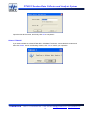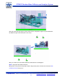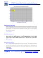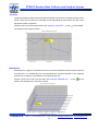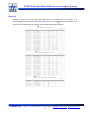
1
PT690 Vibration Data Collector and Analysis System
PT690 Vibration Data Collector
User Manual
Installation, Operation, Maintenance
ProvibTech.
11011 Brooklet Dr., Ste 360, Houston, TX 77099, USA
Phone: +1-713-830-7601, Fax: +1-281-754-4972, Email: [email protected] , Web: www.provibtech.com
PT690-USR-B-6 Copyright © 2007 by ProvibTech
ProvibTech
Phone: +1-713-830-7601 Fax: +1-281-754-4972 [email protected] , www.provibtech.com
1
PT690 Vibration Data Collector and Analysis System
Table of Content
PT690 Vibration Data Collector Introduction.................................................................................................................................3
Introduction......................................................................................................................................................... 3
Features............................................................................................................................................................... 4
Electrical ............................................................................................................................................................. 4
Physical............................................................................................................................................................... 5
Software Running Environment ......................................................................................................................... 6
PT690-DC Data Collector Installation............................................................................................................................................7
Field Wiring Diagram......................................................................................................................................... 7
Keyboard ............................................................................................................................................................ 8
PT690-DC Data Collector Operation............................................................................................................................................10
Charge PT690-DC ............................................................................................................................................ 10
PT690-DC Operation........................................................................................................................................ 10
View Measurement Result................................................................................................................................ 12
PCM690LT Software Operation...................................................................................................................................................13
PCM690LT features ......................................................................................................................................... 13
Software Install and Uninstall........................................................................................................................... 13
Software Running and Exit............................................................................................................................... 16
Device Management ......................................................................................................................................... 16
Switch Device................................................................................................................................................... 19
Setup Menu....................................................................................................................................................... 20
File Menu.......................................................................................................................................................... 26
Edit Menu ......................................................................................................................................................... 27
Analysis Menu .................................................................................................................................................. 33
View Menu ....................................................................................................................................................... 37
Communication Menu ...................................................................................................................................... 42
Window Menu .................................................................................................................................................. 44
Help Menu ........................................................................................................................................................ 44
PT690 System Maintenance .........................................................................................................................................................45
Accessories ....................................................................................................................................................... 45
Troubleshooting................................................................................................................................................ 45
CAUTION ........................................................................................................................................................ 45
Appendix I. Glossary ....................................................................................................................................................................46
ProvibTech
Phone: +1-713-830-7601 Fax: +1-281-754-4972 [email protected] , www.provibtech.com
2
PT690 Vibration Data Collector and Analysis System
PT690 Vibration Data Collector Introduction
Introduction
PT690 system consists of PT690-DC data collector and PCM690LT analysis software.
ProvibTech provides a cost effective, yet feature rich solution in machine condition monitoring.
The PT690 is ideal for large plants which require several vibration data collectors and/or for
plants with a limited budget in condition monitoring.
PT690-DC will collect and store waveform, spectrum, overall vibration and alarm status of each
point in a route. It also processes the information and displays the measurement-point ID, the last
measurement data, the overall vibration, and the alarm status. With the PT690, a user has the
ability to manually enter process variables which are then recorded by the PT690.
With advanced digital processing, this “smart measurement” is available to display acceleration,
velocity and displacement simultaneously. It is simple to use; any field service personnel can use
the PT690-DC with little or no training.
Once the collected data from the PT690 is up-loaded to the PCM690 analysis software, one may
analyze the machine condition with: alarm list, spectrum, trend, or with a visual inspection of a
machine image to obtain an understanding of the machine condition.
For vibration expert who requires additional information for analysis, the PCM690 offers
waveform, spectrum, and waterfall for each measured point. With further analysis of each plot
ProvibTech
Phone: +1-713-830-7601 Fax: +1-281-754-4972 [email protected] , www.provibtech.com
3
PT690 Vibration Data Collector and Analysis System
with harmonics, sideband, zoom, mark, etc, one can also compare the collected spectrum with
standard spectrum to locate deviations.
ProvibTech offers a network type, PCM690-SQL, which interfaces with Microsoft SQL database.
Data from any computer (various subsidiary companies or locations) can be up-loaded to a
central SQL database server.
Features
9
Simultaneously
measuring
acceleration,
velocity and displacement
9
Route is programmable up to 500 points
9
User friendly interface
9
Powerful analysis software with spectrum,
waveform, waterfall, trend and machine image
9
4 lines display with back light
9
Auto power off
9
Hand input process data
9
Machine image with condition status and
overall level
9
Software supports multiple data collectors
9
Cost effective solution for in-depth condition monitoring
9
Simple up-grade from vibration meter
Electrical
9
9
Frequency Response (+/- 3db)
Acceleration:
2 ~ 1,000 Hz
Velocity:
5 ~ 1,000 Hz
Displacement:
5 ~ 1,000 Hz
Measurement Range
Acceleration (pk or RMS): 0 ~ 20g
Velocity (pk or RMS): 0 ~ 100 mm/sec (0 ~ 4 in/sec)
Displacement (pk-pk): 0 ~ 2,000 um (0 ~ 80 mil)
Process Variable: Hand input
Peak and pk-pk are RMS converted.
9
Waveform and Spectrum
ProvibTech
Phone: +1-713-830-7601 Fax: +1-281-754-4972 [email protected] , www.provibtech.com
4
PT690 Vibration Data Collector and Analysis System
Collect and store 1,000 data for each point.
400 lines of resolution in spectrum
9
Route
64 maximum PT690-DC.
500 maximum measurement-points.
Route can be configured to three hierarchy layers with Machine-Train, Machine, and point.
Each point can be configured to measure acceleration, velocity, and displacement or have a hand
input.
Manual hand input can be any number such as thrust position, or process variable.
Each point has its own point ID with up to 12 letters or number.
9
Alarms
Dual alarms for each point.
9
Display
LCD 128 * 64 with blue backlight, 4 lines, 18 letters
PT690-DC will display point ID, last measurement data, current measurement data, unit, Alarm
status, and battery status
9
Power Converter
90 ~ 250 VAC, 5W
9
Battery
Li-H rechargeable battery 1100mAH
9
Measurement Error: +/- 5%
9
Data transfer
Once the data collector receives the machine route and point configuration information, it uploads
the last measured data to the host PC for in-depth analysis and data storage.
9
Memory
RAM 10Mb
ROM: Flash, 10Mb
9
Approval:
CE
Hazardous area CEC approval: iaIICT4
Physical
9
Temperature
Operation: -20oC ~ + 65oC (-4oF ~ +140oF)
Storage: -40oC ~ + 85oC (-40oF ~ +185oF)
9
Dimension
ProvibTech
Phone: +1-713-830-7601 Fax: +1-281-754-4972 [email protected] , www.provibtech.com
5
PT690 Vibration Data Collector and Analysis System
180mm * 82mm * 53mm (7in * 3.2in * 2in)
9
Weight
240g (0.5lb)
Software Running Environment
9
Operation System: Windows 2000 or Windows XP
9
CPU: P4 2.0GHz
9
Memory: 512MB
9
Hard Disk: 40G
9
Display: VGA
ProvibTech
Phone: +1-713-830-7601 Fax: +1-281-754-4972 [email protected] , www.provibtech.com
6
PT690 Vibration Data Collector and Analysis System
PT690-DC Data Collector Installation
Field Wiring Diagram
Field Wiring Diagram 1
Field Wiring Diagram 2
ProvibTech
Phone: +1-713-830-7601 Fax: +1-281-754-4972 [email protected] , www.provibtech.com
7
PT690 Vibration Data Collector and Analysis System
Keyboard
4 lines display with backlight
AVD
Up
M
M
ID
Down
ON/OFF
OK
Numbers
Positive/Minus Sign
Dot Sign
Above picture shows structure of the keyboard and display.
Keyboard Description
9
M: Press this button to start data collection.
9
AVD: Press this button to switch to the smart AVD. Smart AVD is a type of measurement-point
which is special for PT690-DC and pre-defined. Smart AVD is used to measure acceleration,
velocity, displacement. Smart AVD is displayed by default when PT690-DC is turned on. If
customer chooses the smart AVD and presses M, PT690-DC will connect data continuously unless
customer switches to another measurement-point. PT690-DC won’t stop collection until you press
M again.
9
Up: Press this button to switch to the previous measurement-point.
9
Down: Press this button to switch to the next measurement-point.
9
ON/OFF: Press this button to turn on or turn off PT690-DC.
9
ID: Press this button to input ID of some measurement-point. Press OK and after it, PT690-DC will
switch to this measurement-point. It’s convenient for you to view information of this
measurement-point.
9
OK: Confirm current operation for measurement-points.
9
Positive/Minus Sign: Positive sign and minus sign input.
9
Dot Sign: Dot Sign input.
9
0, 1……9: Numeric input.
ProvibTech
Phone: +1-713-830-7601 Fax: +1-281-754-4972 [email protected] , www.provibtech.com
8
PT690 Vibration Data Collector and Analysis System
4 Lines Display
9
Smart AVD: line1 displays measurement-point name while line1, line2 and line3 respectively
display measure value of acceleration, velocity and displacement.
9
Normal routing measurement-point: line1 and line 2 will display point name by format of
point ID: machine-train machine measurement-point. Line3 indicates measure value and
line4 displays alarm status.
9
The display will first show the full-name of the routing point, and then shrink into two lines.
9
If this is not the first measurement, when you just turn to this measurement point, you will
see an indication of the last measurement for 2 seconds, and then ready for this
measurement.
9
For vibration that over the alarms set-point, alert will show as A and danger will show a D on
line 4 after the measurement.
Backlight and Power
9
PT690-DC will shut down the backlight in two minutes after no user action. User can activate
the backlight by pressing any numerical key.
9
PT690-DC will automatically turn off in three minutes after no user action.
9
Communication with the computer: PT690-DC must be turned on with backlight; otherwise it
will display Connection error.
ProvibTech
Phone: +1-713-830-7601 Fax: +1-281-754-4972 [email protected] , www.provibtech.com
9
PT690 Vibration Data Collector and Analysis System
PT690-DC Data Collector Operation
Charge PT690-DC
1.> First time to use PT690-DC, charge the battery for 8 hours.
2.> Press ON/OFF button to operate PT690-DC.
3.> Charging indication: If screen displays use it before charged up, it indicates that the
rechargeable battery needs to be charged. If power is low, PT690-DC will stop working.
4.> In normal operation condition, each charge will maintain PT690-DC operation for about 12
hours.
PT690-DC Operation
Download Routing
1.> You must download routing information before using it.
2.> Run PCM690LT software and make sure that PT690-DC is connected with your computer
and turned on.
3.> Following the steps: See below.
9
For a new PT690 Device first connecting to the upper-computer, following window will
appear:
9
For a PT690 Device connecting to the upper-computer, the point’s information in
upper-computer has changed, following window will appear:
ProvibTech
Phone: +1-713-830-7601 Fax: +1-281-754-4972 [email protected] , www.provibtech.com
10
PT690 Vibration Data Collector and Analysis System
CAUTION: the point’s information contains point’s number, points parameters setup, trains
setup, machines setup.
9
And for a PT690 Device connecting to the upper-computer, point’s information hasn’t
changed but new data is collected to upload, following window appears:
a)
Select Communication->Download measurement point parameter to download
updated measurement-point information to PT690-DC.
b)
Click Communication->Download Metric/English Unit to download unit information for
PT690-DC.
Select the measurement-point from Route
1.> Press AVD, the screen will display Point: Smart AVD.
2.> Press Up, ID will back to the previous point; in the same way, press Down, ID will forward to
the next point. Screen will show detailed information of these points at the same time.
3.> Or enter the point ID you needed. Press ID and PT690-DC will jump to this point directly.
Screen will show detailed information of this point.
Perform Measurement
1.> Select the point by the methods mentioned in Select the measurement-point from Route.
2.> Put the transducer on the respected location on machine.
ProvibTech
Phone: +1-713-830-7601 Fax: +1-281-754-4972 [email protected] , www.provibtech.com
11
PT690 Vibration Data Collector and Analysis System
3.> Press M to measure. Waiting for several seconds, PT690-DC will display vibration value and
alarm status.
4.> If there is no transducer or the transducer is not well connected, PT690-DC will display check
the connection of the sensor and the cable.
5.> If the measurement-point is a manual input point, you can manually enter the measurement
value and then pressing M or OK.
6.> Select the next measurement point.
7.> Repeat above steps until all measurement-points finished measurement.
Data Upload
1.> Connect PT690-DC with your computer and run PCM690LT software. Turn on PT690-DC.
2.> If connection correct and there is new data to upload, a window below will pop-up and
Communication->Upload Data will be enabled.
3.> You can upload new data to your computer by clicking this command.
CAUTION:
9
Do not operate PT690-DC when it is downloading from upper-computer.
9
As long as PT690-DC communicates with the upper-computer (downloading or uploading),
the display TRANSFERRING DATA will always appear. At this time, customer can not
operate PT690-DC. Customers should disconnect the cable between PT690DC and
upper-computer if want to operate PT690-DC.
View Measurement Result
The same as Select the measurement-point from Route, after selecting the point, and if this
point has already completed measurement, screen will display the results.
ProvibTech
Phone: +1-713-830-7601 Fax: +1-281-754-4972 [email protected] , www.provibtech.com
12
PT690 Vibration Data Collector and Analysis System
PCM690LT Software Operation
PCM690LT features
Basic Analysis:
9
Route
9
Running status on machine image
9
Trend plot
9
Alarm list
9
Overall vibration list
9
Advanced Analysis:
9
Waveform plot
9
Spectrum plot
9
Spectrum with standard waveform
9
Waterfall plot
Functions:
9
Marker
9
Zoom
9
Harmonics
9
Sideband
9
Works with multiple data collectors
9
Print
9
System configuration
9
English or metric unit
Operation System:
9
Windows 2000 or Windows XP
Software Install and Uninstall
Installation
Put the installation CD into CD-driver, supposing that the CD-driver is G and then double-click file
of Setup.exe in directory of G:\ to start this installation programme.
1.
Show welcome information. Click Next to continue.
ProvibTech
Phone: +1-713-830-7601 Fax: +1-281-754-4972 [email protected] , www.provibtech.com
13
PT690 Vibration Data Collector and Analysis System
2.
Choose destination location and then click Next to continue.
3.
Click Next to continue the installation process. If you see Locked File Detected window,
mark the check box Don’t display this message again and then click Ignore to continue.
4.
Click Next until the installation complete. And then click Finish. Select whether to restart
your computer.
ProvibTech
Phone: +1-713-830-7601 Fax: +1-281-754-4972 [email protected] , www.provibtech.com
14
PT690 Vibration Data Collector and Analysis System
Uninstall
You can uninstall PCM690LT software in two ways below:
1.
Open Start/All Programs/PCM690->Uninstall to uninstall PCM690LT software. Click OK in
following window.
2.
Open the control panel; double-click command of Add/Remove Programme. Choose
PCM690 from this page and then click Add/Remove to uninstall this software.
ProvibTech
Phone: +1-713-830-7601 Fax: +1-281-754-4972 [email protected] , www.provibtech.com
15
PT690 Vibration Data Collector and Analysis System
Software Running and Exit
Two methods to run PCM690LT software:
9
Double-click shortcut of PCM690LT on the desktop;
9
Click Start/All Programs/PCM690->PCM690LT in programme menu.
Click File->Exit to quit from PCM690LT software.
Device Management
Click Setup->Device Management… to open Device Management window.
Add a new PT690-DC
Make sure a new PT690-DC connects to your computer and well communicates with the
computer. Click Add on Device Management window, if no new PT690-DC is connected, the
following window will appear:
ProvibTech
Phone: +1-713-830-7601 Fax: +1-281-754-4972 [email protected] , www.provibtech.com
16
PT690 Vibration Data Collector and Analysis System
Or you will see the window below.
Click OK to open Add Device window.
9
Device Name: Named for this PT690-DC.
9
Device SN: The SN which is pre-defined is used to identify this new PT690-DC.
Finally, click OK to complete this operation.
Modify Device Name
If more than one PT690-DC has existed in PCM690LT software, click the device name in Device
List and then click Modify to open Modify Device Information… window.
ProvibTech
Phone: +1-713-830-7601 Fax: +1-281-754-4972 [email protected] , www.provibtech.com
17
PT690 Vibration Data Collector and Analysis System
Input the new device name, and finally click OK to complete it.
Delete a PT690-DC
If you want to delete an existed PT690-DC in PCM690LT software, choose the device name and
then click Delete. And in the following window, click Yes to confirm your operation.
ProvibTech
Phone: +1-713-830-7601 Fax: +1-281-754-4972 [email protected] , www.provibtech.com
18
PT690 Vibration Data Collector and Analysis System
Switch Device
If the current user view doesn’t match the PT690-DC which is going to connect with
upper-computer, your can click File->Switch Device… to switch to the correct user view.
9
Select the correct device name in Device Name list above and then click Switch to switch to
the correct PT690-DC.
9
Mark the check box Login this device by default and next time you run PCM690LT software,
you will log on the user view of the PT690-DC you had selected in list of Device Name.
CAUTION:
Maximum 64 PT690-DC are allowed.
ProvibTech
Phone: +1-713-830-7601 Fax: +1-281-754-4972 [email protected] , www.provibtech.com
19
PT690 Vibration Data Collector and Analysis System
Setup Menu
System Setup
Click Setup->System Setup… to System Setup window.
9
Unit: Setup the unit mode of measured data in PCM690LT software (English Unit or Metric).
9
Spectrum Depth: Setup the maximum spectrum depth.
9
Trend Depth: Setup the maximum trend depth.
Machine Train Management
Click Setup->Machine Train Management… to open Machine Train Management window.
Add a new machine-train
Click Add to add a new machine-train.
ProvibTech
Phone: +1-713-830-7601 Fax: +1-281-754-4972 [email protected] , www.provibtech.com
20
PT690 Vibration Data Collector and Analysis System
Enter a new machine-train name and then click OK to save the operation.
CAUTION:
Maximum 32 machine-trains are allowed under a PT690-DC.
Modify machine-train name
Choose a machine-train in the list and click Modify to rename this machine-train. Enter the new
name and then click OK to save this operation.
Delete a machine-train
Choose a Machine-Train name and click Delete. Click Yes to delete all information of this
machine-train from PCM690LT software.
ProvibTech
Phone: +1-713-830-7601 Fax: +1-281-754-4972 [email protected] , www.provibtech.com
21
PT690 Vibration Data Collector and Analysis System
Machine Management
Click Setup->Machine Management… to open Machine Management window.
Add a new machine
Choose a machine-train first and then click Add to open Add Machine window.
9
Machine Name: enter the new machine name.
9
Picture Path: choose a picture (*.bmp) for this new machine. Click Choose Picture and
choose the picture path for the new machine.
Finally, Click OK to save the operation.
CAUTION:
9
Maximum 128 machines are allowed under a PT690-DC.
9
Pictures only by *.bmp format are allowed.
Modify machine information
Choose name of the machine to be modified and click Modify to open Modify Machine window.
ProvibTech
Phone: +1-713-830-7601 Fax: +1-281-754-4972 [email protected] , www.provibtech.com
22
PT690 Vibration Data Collector and Analysis System
9
Rename this machine or appoint a new picture (*.bmp) for this machine.
9
Click OK to save this operation.
Delete a machine
Choose name of the machine to be deleted, and then click Delete. Finally, click Yes in following
window to delete all information about this machine from PCM690LT software.
ProvibTech
Phone: +1-713-830-7601 Fax: +1-281-754-4972 [email protected] , www.provibtech.com
23
PT690 Vibration Data Collector and Analysis System
Measure Point Management
Click Setup->Measure Point Management… to open Measurement Point Management window.
Add a new measurement-point
Choose a machine under some machine-train in the list and then click Add to add a new point.
9
Measurement Point Name: Name for this new point.
9
Picture Path: Choose a picture (*.bmp) for this point. Click Choose Picture to select the
picture path.
9
Measurement Point Type: Choose measurement type of the transducer located on this
point: Acc (Acceleration), Vel From Acc (from Acceleration to Velocity), Dis From Acc (from
Acceleration to displacement), and Hand Input. For Hand Input point, you can not view the
waveform plot, spectrum plot, and trend plot.
9
Measurement Type: Choose type of the measurement value: PK, PK-PK, and RMS.
9
Spectrum Resolution: Appointed by PCM690LT software. The default is 400.
9
Sampling Frequency: Appointed by PCM690LT software. The default is 2000.
9
Work Frequency: The actual work frequency of the machine-train. It is appointed by
customer
ProvibTech
Phone: +1-713-830-7601 Fax: +1-281-754-4972 [email protected] , www.provibtech.com
24
PT690 Vibration Data Collector and Analysis System
9
Sensitivity: Sensitivity of the transducer located on this point. The value is given by the
factory which provides this transducer.
9
Full Scale Range: Two levels: full scale high and full scale low.
9
Alarm Range: Four levels: Danger High, Alert High, Alert Low, and Danger Low.
CAUTION:
9
Maximum 500 measurement-points are allowed under a PT690-DC.
Modify information of measurement-point
Choose name of the point to be modified and then click Modify to open Modify Measurement
Point window.
Delete a measurement-point
Choose name of the point to be deleted, and then click Delete. Finally, click Yes in following
window to delete all information about this point from PCM690LT software.
ProvibTech
Phone: +1-713-830-7601 Fax: +1-281-754-4972 [email protected] , www.provibtech.com
25
PT690 Vibration Data Collector and Analysis System
File Menu
Open Database
Click File->Open Database…to choose a storage path of the pre-defined database and open this
database.
In PCM690LT software, information about all PT690-DC devices, trains, machines, points are
saved in the database. The name of this database in PCM690LT software is Vibrate and this
name is defined by software and can not be changed by customers.
If you click Open Database and choose a directory [E:\PCM690\Vibrate], that’s meaning you
want to open Vibrate in directory of [E:\PCM690].
Customer can not change the database name. And if the file is inexistent, you will fail to open this
Vibrate.
Backup Database
Click File->Backup Database… and choose a path, then you will save a file named Vibrate which
notes information about all PT690-DC, trains, machines, points under these devices in the path.
For example: if you choose E:\PCM690LT as the backup path, the database-file named Vibrate
will save in the directory of E:\PCM690LT.
Restore Database
If the database is damaged by some unpredictable factors when you are running PCM690LT
software, and you had backup this database before, then you can restore the database by
clicking File->Restore Database…. Select this command and choose the path of the restored
database, then the database will be copied to the directory in which the damaged database is
saved.
For example: if the database you backup is in directory of E:\ and the target path is C:\PCM690,
you should choose the path as E:\Vibrate. And the file Vibrate in path of E:\ will be copied to the
target path and replace the damaged one.
Print, Print Preview, and Print Setup
Print Setup
Click File->Print Setup… to setup the property of the printer and paper.
Print Preview
Click File->Print Preview… to preview the graphs or sheets you are going to print.
ProvibTech
Phone: +1-713-830-7601 Fax: +1-281-754-4972 [email protected] , www.provibtech.com
26
PT690 Vibration Data Collector and Analysis System
Print
Click File->Print… to print the current graph or sheet.
Edit Menu
Rename and Delete
Right-click a node in the tree view (the node can be a train, a machine or a point), and then the
relative menu will pop up.
9
Rename: Click Rename… in above menu or click Edit->Rename…menu to appoint a new
name.
9
Delete: Click Delete in above menu or click Edit->Delete…menu to delete this node from
PCM690LT software.
Edit Picture
In PCM690LT software, we provide tools to let customers edit pictures for machines and points in
range of the user view. With command of Edit Picture, the user interface is displayed friendlier.
Following, we give an entire example to edit pictures for machine-trains, machines and points.
Example:
In the following example, we create a new machine-train named Train2. Under Train2, we create
two machines Machine1 and Machine2. Also we create two points under Machine1: Point1 and
Point2; we create two points under Machine2: Point3 and Point4. Customers can consult User
Manual to get information about how to create a new machine-train (machine or point). After you
complete the setup on new machine-train, machines and points, you will see the following user
view:
ProvibTech
Phone: +1-713-830-7601 Fax: +1-281-754-4972 [email protected] , www.provibtech.com
27
PT690 Vibration Data Collector and Analysis System
In the above window, you will see pictures about machines and points are in the top left corner,
so the next you should do is to edit those pictures in a proper location you want.
Following the steps:
Step1: Click Edit->Edit Picture… to mark it;
Step2: Choose a picture and left-press the mouse to drag this picture to a proper location in the
view region.
Step3: Repeat Step2 until all pictures are moved to a proper location. Supposing that we had
moved pictures to the location described in the following picture.
Step4: Link machine and machine with a line.
Right-click picture of Machine2, a menu will pop-up.
ProvibTech
Phone: +1-713-830-7601 Fax: +1-281-754-4972 [email protected] , www.provibtech.com
28
PT690 Vibration Data Collector and Analysis System
Click Link Machine command and then click picture of Machine1. After you did that, a line
connects Machine2 to Machine1 appears.
If you want cancel the line between Machine1 and Machine2, you can do the following operation.
Right-click picture of Machine2 again and you will see command Link Machine.
ProvibTech
Phone: +1-713-830-7601 Fax: +1-281-754-4972 [email protected] , www.provibtech.com
29
PT690 Vibration Data Collector and Analysis System
Click this command and finally click the location which is beyond the region of picture Machine1
and Machine2 (just click blank place in the view).
After you did that, the line between Machine2 and Machine1 will disappear.
Step5: Link points with relative machine.
Drag picture of the points to the proper location. Right-click picture of Point3 and command Stud
on Machine Picture will pop up.
ProvibTech
Phone: +1-713-830-7601 Fax: +1-281-754-4972 [email protected] , www.provibtech.com
30
PT690 Vibration Data Collector and Analysis System
Click this command and click the very location on picture of Machine2. The result is shown
below.
If Point3 doesn’t belong to Machine2, another window will appear to notice you.
Step6: Repeat Step5 until you complete it. The result is below:
ProvibTech
Phone: +1-713-830-7601 Fax: +1-281-754-4972 [email protected] , www.provibtech.com
31
PT690 Vibration Data Collector and Analysis System
Set As the Standard Data
Standard data is appointed by customer. You can but appoint one standard data under a point.
Once the standard data is appointed, you can compare waveforms painted by different data
streams with the standard waveform to observe the running condition of machine-trains.
Delete Point Data
9
Right-click a point in the tree view and then click Delete Point Data… in the listed menu.
9
Click a point in the tree view and then click Edit->Delete Point Data…. Following window
appears: click Yes and then you will delete all data (all piece) under this point.
ProvibTech
Phone: +1-713-830-7601 Fax: +1-281-754-4972 [email protected] , www.provibtech.com
32
PT690 Vibration Data Collector and Analysis System
Analysis Menu
Waveform Plot
Waveform plot is a type of plots which presents or displays the function relation between
instantaneous amplitude of signal and time. In a waveform plot, the X-axis represents time
domain, and the Y-axis represents amplitude. Compare the waveform plot with the pasted to
analyze the variational trend of the amplitude.
Choose a piece under a point right-hand the user view and then click Analysis->Waveform Plot…
or click
on the toolbar. The waveform plot is below:
Spectrum Plot
Spectrum plot is an XY plot in which the X-axis represents vibration frequency and the Y-axis
represents vibration amplitude. Choose a piece under a point right-hand the user view and then
click Analysis->Spectrum Plot… or click
ProvibTech
on the toolbar. The spectrum plot is below:
Phone: +1-713-830-7601 Fax: +1-281-754-4972 [email protected] , www.provibtech.com
33
PT690 Vibration Data Collector and Analysis System
Shaft XY Vibration Graph-Overall
Overall vibration graph presents the correspondence relations on the amplitude of channel X and
channel Y. Measurement-points which have the dual-channels are allowed to show the overall
vibration graph. The X-axis represents the amplitude of channel X, and then Y-axis represents
the amplitude of channel Y.
**Future Release
Shaft XY Vibration Graph-1x
1X: In a complex vibration signal, notation for the signal component that occurs at the rotative
speed frequency, also called synchronous. 1X Shaft XY vibration graph is a type of overall
vibration graph in which the vibration frequency equals to the components of shaft rotation
speed.
** Future Release
Shaft XY Vibration Graph-2x
2X: In a complex vibration signal, notation for signal components having frequencies equal to
exact two times of shaft rotative speed, also called harmonic. 2X Shaft XY vibration graph is a
type of overall vibration graph in which the vibration graph equals to exact two times of shaft
rotative speed.
**Future Release
ProvibTech
Phone: +1-713-830-7601 Fax: +1-281-754-4972 [email protected] , www.provibtech.com
34
PT690 Vibration Data Collector and Analysis System
Trend Plot
Trend plot presents a relation with the measured variable versus time in Cartesian format or polar
format. The X-axis of trend plot in Cartesian format represents the time domain and the Y-axis
represents vibration amplitude.
Choose a point on the tree view and then click Analysis->Trend Plot… or click
on the toolbar.
The trend plot of this point is below:
Waterfall Plot
Waterfall plot is a graph in Cartesian format which presents amplitude versus frequency spectra
at series time. In a waterfall plot, time and amplitude are usually presented on two separate
vertical axes. Frequency is measured on the horizontal (X) axis.
Choose a point on the tree view and then click Analysis->Waterfall Plot… or click
on the
toolbar. The waterfall plot of this point is below:
ProvibTech
Phone: +1-713-830-7601 Fax: +1-281-754-4972 [email protected] , www.provibtech.com
35
PT690 Vibration Data Collector and Analysis System
Alarm List
Choose a node on the tree view (this node can be a machine-train, a machine, or a
measurement-point), and then click Analysis->Alarm List… or click
button on the toolbar. The
alarm list of a machine-train, a machine, and a measurement-point is below:
ProvibTech
Phone: +1-713-830-7601 Fax: +1-281-754-4972 [email protected] , www.provibtech.com
36
PT690 Vibration Data Collector and Analysis System
View Menu
Toolbar and Status Bar
Toolbar:
(1): Open database
(2): Backup database
(3): Restore database
(4): Switch device
(5): User view
(6): Edit picture information
(7): View waveform plot
(8): View spectrum plot
(9): View overall vibration graph
(10): View 1X shaft XY vibration graph
(11): View 2X shaft XY vibration graph
(12): View plots painted by standard data
(13): View frequency multiply information in one spectrum plot
(14): View side band information in one spectrum plot
(15): View trend plot
(16): View waterfall plot
(17): View alarm list
(18): Plots zoom in
(19): Plots Restore
(20): View information about copyright and version information of PCM690LT software
Status Bar:
Display or hide the status bar.
The status bar will display the description of the selected commands. And also the keypad status.
ProvibTech
Phone: +1-713-830-7601 Fax: +1-281-754-4972 [email protected] , www.provibtech.com
37
PT690 Vibration Data Collector and Analysis System
Big Icon, Small Icon, List, and Details
Big Icon:
Show data streams under points by big icon.
Small Icon:
Show data streams under points by small icon.
List:
List data streams under points by order of the collection time (from late to early).
Details:
Show detailed information of data streams (Collection time and Measure value) under points by
order of the collection time (from late to early).
User View
User View in PCM690LT is a type of view which presents hierarchy layers with machine-train,
machine, and measurement-point of a PT690-DC.
Left-hand of our user view is tree view which presents three hierarchy layers with machine-train,
machine and measurement-point. Select an item in tree view, on the right hand side, windows
will display information about this item. For example you select a measurement-point, window
right-hand will display measurement data streams under this measurement-point.
The color of measurement-point icons indicates:
9
Green: OK
9
Yellow: Alarm
9
Red: Danger
Definition of alarms:
9
For vibration measurement, if the overall is higher than the set-point, alarm will be triggered.
9
For displacement or process variable, the set-point will be a range with high and low
set-point. If the overall is beyond this range, alarm will be triggered.
9
Only status of the most recent measured date will be displayed.
9
A machine status will be the most severe status of its point.
9
A machine train status will be the most severe status of its machines.
ProvibTech
Phone: +1-713-830-7601 Fax: +1-281-754-4972 [email protected] , www.provibtech.com
38
PT690 Vibration Data Collector and Analysis System
Zoom in and Restore
Zoom in:
When you are viewing a plot (The plot can be a waveform plot, a spectrum plot, or a trend plot),
click Edit->Zoom In… or
button on toolbar. Finally, move your mouse to select a rectangular
region. The plot in this region will zoom in.
Above picture shows the original waveform plot before zooming in while below picture shows
waveform plot which has zoomed in.
9
After the magnification, the plot can be dragged or move around to display other part of this
plot.
9
Just drag your mouse to complete it.
Restore:
Click View->Restore… or
ProvibTech
on toolbar to restore the magnified plot to its original size.
Phone: +1-713-830-7601 Fax: +1-281-754-4972 [email protected] , www.provibtech.com
39
PT690 Vibration Data Collector and Analysis System
Frequency Multiply
When you are viewing the spectrum plot, click Edit->Frequency Multiply… or click
on the
toolbar. If you select a point L on the plot now, the spectrum plot will show four points near L
which are marked by Red Furcation. Importantly, the frequency values which the four points are
relevant to are n times as many as the frequency value of point L.
Side Band
When you are viewing the spectrum plot, click Edit->Side Band… or click
on the toolbar. If you
click a point M on the plot, spectrum plot will display five peak-value points nearest to M, at the
same time, the five points will be marked by Red Furcation.
ProvibTech
Phone: +1-713-830-7601 Fax: +1-281-754-4972 [email protected] , www.provibtech.com
40
PT690 Vibration Data Collector and Analysis System
Standard Data
If you had appointed the standard data, you can view the stand waveform when you are viewing
a waveform plot or a spectrum plot.
Click View->Standard Data… or click
on the toolbar to view the standard waveform plot or
standard spectrum plot.
ProvibTech
Phone: +1-713-830-7601 Fax: +1-281-754-4972 [email protected] , www.provibtech.com
41
PT690 Vibration Data Collector and Analysis System
Communication Menu
Scan Device
Click Communication->Scan Device… and you will see following window:
Ensure that:
9
PT690-DC has well connected with the upper-computer;
9
PT690DC has turned on
Following windows may appear:
9
Succeed in communicating with the PT690-DC:
9
Succeed in Communicating with the PT690-DC and new data is collected.
ProvibTech
Phone: +1-713-830-7601 Fax: +1-281-754-4972 [email protected] , www.provibtech.com
42
PT690 Vibration Data Collector and Analysis System
9
Succeed in communicating with the PT690-DC and data in PCM690LT software has
changed.
Download measurement point parameter
If data in PCM690LT software has changed, you should re-download the data to PT690-DC. Just
click Communication->Download measurement point parameter… to complete it.
Upload Data
If there is new data in PT690-DC, you should upload the data to the upper-computer. Just click
Communication->Upload Data… to complete it.
Download Metric/English Unit
Click Communication->Download Metric/English Unit… to setup the unit mode for PT690-DC.
Choose the proper unit mode and then click Download to download the unit mode to PT690-DC.
ProvibTech
Phone: +1-713-830-7601 Fax: +1-281-754-4972 [email protected] , www.provibtech.com
43
PT690 Vibration Data Collector and Analysis System
Window Menu
Cascade: Overlap all the opened windows.
Tile: Tile all the opened windows.
Arrange Icons: List all minimized windows in the bottom of the main windows.
Help Menu
Help Topic: Show on-line help.
About PCM690LT: Show version, build serial number, copyright and creator of PCM690LT
software.
ProvibTech
Phone: +1-713-830-7601 Fax: +1-281-754-4972 [email protected] , www.provibtech.com
44
PT690 Vibration Data Collector and Analysis System
PT690 System Maintenance
Accessories
9
TM0782A:
Accelerometer
9
PT690-case:
PT690 system carrying case
9
PT600-TP:
Accelerometer tip, 50mm
9
PT600-MG:
Magnet for accelerometer
9
PT690-CB1:
Cable for data collector and computer
9
PT690-CB2:
Cable for data collector and accelerometer
9
PT690-CB3:
Cable for data collector and BNC port
9
PT690-BATT:
Rechargeable battery
9
PT690-PWR:
Power converter
9
PT690-DC-CASE:
PT690-DC case
9
PT690-USR:
User manual
9
PT690-PC:
Laptop PC configured for PT690
Troubleshooting
PT690-DC can not be turned on
1.
Charge the battery for 8 hours. Then try to turn on PT690-DC.
2.
With the external power attached, try to turn on PT690-DC.
No communication between PT690-DC and PC
1.
PT690-DC turned on with backlight.
2.
Cable PT690CB-1 is OK.
No data collected with PT690-DC and the sensor
1.
Sensor is bad.
2.
Cable is broken.
CAUTION
1.
Do not operate PT690-DC when it is communicating (uploading or downloading) with the
upper-computer!
2.
As
long
as
PT690-DC
communicates
with
the
upper-computer,
the
display
TRANSFERRING DATA will always appear. At this time, customer can not operate
PT690-DC.
Customers
should
disconnect
the
cable
between
PT690DC
and
upper-computer if want to operate PT690-DC.
ProvibTech
Phone: +1-713-830-7601 Fax: +1-281-754-4972 [email protected] , www.provibtech.com
45
PT690 Vibration Data Collector and Analysis System
Appendix I. Glossary
* Absolute Vibration
Vibration of an object as measured relative to an inertial (fixed) reference frame. Accelerometers and
velocity transducers measure absolute vibration typically of machine housings or structures; thus they are
referred to as seismic transducers or inertial transducers.
* Acceleration
The time rate of change of velocity. For harmonic motion, this is often expressed as g or a. Typical units for
acceleration are feet per second per second (ft/s2), meters per second per second (m/s2), or more
commonly "g" (where g = acceleration of earth's gravity = 386.1 in/s2 = 32.17 ft/s2 = 9.81 m/s2).
Acceleration measurements are generally made with piezoelectric accelerometers and are typically used to
evaluate high frequency machine casing or bearing housing response characteristics.
* Accelerometer
An accelerometer is an inertial transducer which converts the acceleration characteristic of vibration into a
proportional electric signal.
* Acceptance Region
Trend information of the 1X or 2X vibration vectors (amplitude and phase lag angle) presented in polar
format, or the shaft average centerline position in Cartesian format.
The user defines the normal
Acceptance Region for each shaft radial vibration or position measurement on the machine, based on
historical data for the machine under all normal operating conditions.
Some systems provide hardware and/or software alarm (Alert and Danger) set point capability. Alarm set
points are set independently for maximum and minimum values of both amplitude and phase. Acceptance
Region information is the most important indicator of a shaft crack.
* Aero-derivative
Aircraft jet engines that have been adapted and modified for industrial use.
* Aliasing
False frequency components caused by sampling a dynamic signal at too low a sampling frequency. The
sampling frequency must be at least twice the highest frequency of interest or the highest frequency
component in the signal. This effect can be eliminated by adjusting the sampling frequency, or using a
low-pass filter on the signal prior to sampling (anti-aliasing.) The primary disadvantage of anti-aliasing (as is
the case with virtually any type of filtering) is that phase and amplitude errors are incurred.
* Alignment
The positioning of machine components; bearings, rotors, casing, foundation, piping, etc., with respect to
each other for efficient transfer of power. Various alignment requirements utilize different techniques of cold
ProvibTech
Phone: +1-713-830-7601 Fax: +1-281-754-4972 [email protected] , www.provibtech.com
46
PT690 Vibration Data Collector and Analysis System
and hot machine measurement including optical, mechanical (dial indicators), electronic (proximity probes),
and laser.
* Amplification Factor, Non-synchronous
A measure of the susceptibility of a rotor system vibration response to a non-synchronous harmonic exciting
force at a rotor system natural frequency. Synchronous amplification factor differs from non-synchronous
amplification factor due to the existence of destabilizing tangential forces which depend on shaft rotative
speed. At high rotative speeds these destabilizing factors cause a decrease in system quadrature dynamic
stiffness and result in a non-synchronous amplification factor higher than the synchronous amplification
factor.
* Amplification Factor, Synchronous
A measure of the susceptibility of a rotor system vibration response to an imbalance-related exciting force
when shaft rotative speed is equal to a rotor system natural frequency. A calculation technique is similar to
measuring the Q of a filter (the center frequency divided by the bandwidth), i.e., the balance resonance
speed divided by the difference between the speeds at the -3dB amplitude values. Caution should be used
when applying this latter method because of the potential mechanical abnormalities of machinery vibration
response.
In general, a high synchronous amplification factor indicates low system quadrature dynamic stiffness,
whereas a low amplification factor generally indicates high system quadrature dynamic stiffness.
Due to several factors, amplification factor measured during machine startup is different from that measured
during coast down. Also called machine Q, synchronous amplification factor differs from non-synchronous
amplification factor by an amount related to the existence of a tangential force which depends on actual
shaft rotative speed. See Dynamic Stiffness, Quadrature.
* Amplitude
The magnitude of periodic dynamic motion (vibration). Amplitude is typically expressed in terms of signal
level, e.g., millivolts or milliamps, or the engineering units of the measured variable, e.g., mils, micrometres
(for displacement), inches per second (for velocity), etc. The amplitude of a signal can be measured in terms
of peak-to-peak, zero-to-peak, root mean square, or average.
* Amplitude and Phase Versus Time (APHT)
An acronym used to describe the trend plot of plot vibration amplitude and phase data. This data may be
presented in both Cartesian and polar formats. Commonly used for 1X, 2X and nX vibration data.
* Anti-aliasing Filter
A low-pass filter which is used to eliminate false frequency components from the spectrum of a digitally
sampled signal. See Aliasing.
* Anti-Swirl
ProvibTech
Phone: +1-713-830-7601 Fax: +1-281-754-4972 [email protected] , www.provibtech.com
47
PT690 Vibration Data Collector and Analysis System
A technique used in fluid handling machines to decrease or prevent the development of fluid circumferential
flow around the rotor in bearings and seals, and to improve rotor stability.
* Asynchronous or Non-synchronous
Vibration frequency component which is different than shaft rotative speed. Sometimes used to mean any
vibration frequency which is not an integer multiple or fraction of rotative frequency. See Synchronous.
* Attitude Angle
The included angle between the direction of the vector sum of all the unidirectional, steady state, radial
loads (Preloads) on a rotor and a line connecting the bearing and shaft centers. Sometimes confused with
Rotor Position Angle, since the preload historically and incorrectly, was considered to be primarily gravity on
horizontal machines. See Rotor Position Angle and Eccentricity Ratio, Average.
* Average
An amplitude detection technique used for sine wave vibration signals; the half cycle average is 0.637 x
zero-to-peak amplitude. Average amplitude detection is not used by ProvibTech because machinery
vibration signals are most often non-sinusoidal in form and the peak-to-peak, or peak amplitude, cannot be
correctly computed.
* Average Shaft Position
The static or average position of the shaft relative to a stationary component on the machine to which the
probe is mounted. The most common application is rotor axial thrust position relative to the thrust bearing.
Another important application is shaft average radial position in the bearing. These measurements are
made using the dc (position) component of the proximity probe signal. Two proximity probes mounted in an
XY configuration are required for the two-dimensional radial position measurement.
* Axial
In the same direction as the shaft centerline.
* Axial Position
The average position, or change in position, of a rotor in the axial direction with respect to some fixed
reference. Typically, the reference is the thrust bearing support structure or other casing member to which
the probe is mounted. The probe may observe the thrust collar directly or some other integral, axial shaft
surface, as long as it is within about 12 inches of the thrust bearing. Also called thrust position. See
Differential Expansion.
* Balance-of-Plant Machinery
That group of rotating machinery which is not critical to any part of the overall plant process. Many of these
machines operate in tandem or spared installations.
* Balance Resonance Speed
ProvibTech
Phone: +1-713-830-7601 Fax: +1-281-754-4972 [email protected] , www.provibtech.com
48
PT690 Vibration Data Collector and Analysis System
A shaft rotative speed (or speed region) which equals a natural frequency of the rotor system. When a rotor
accelerates or decelerates through this speed region, the observed vibration characteristics are (1) a peak
in the 1X Amplitude and (2) a more rapid change in the 1X vibration phase lag angle.
* Balancing
Adjusting the radical mass distribution of a rotor so that the mass centerline (principal inertia axis)
approaches or coincides with the rotor rotational axis. This reduces the 1X lateral vibration of the rotor and
the forces on the bearings due to imbalance inertia forces.
* Band-Pass Filter
A filter that has a single transmission band extending from a non-zero lower corner frequency to a finite
upper corner frequency. The corner frequencies are the frequencies on either side of the center frequency
where the amplitude is attenuated by 3dB. At the center frequency, the signal amplitude is not attenuated.
* Bandwidth
The span between the corner frequencies of a band-pass filter. Normally expressed in terms of frequency
for constant bandwidth filters and as a percent of the center frequency for constant percentage (constant Q)
filters. See Band-Pass Filter.
* Blade Passing Frequency
A potential vibration frequency on any bladed machine (turbine, axial compressor, fan, propeller, etc.). It
equals the number of blades (on a disk or stage) times shaft rotative speed.
* Bode Plot
A pair of graphs in Cartesian format displaying the 1X vibration vector (phase and amplitude) response as a
function of shaft rotative speed. The Y axis of the top graph represents 1X phase lag angle, while the Y axis
of the bottom graph represents 1X amplitude. The common X axis represents shaft rotative speed.
Sometimes called an imbalance response plot. Also used for 2X, 3X, ETC. .Vibration response vectors.
* Bow
A shaft condition such that the geometric shaft centerline is not straight. Usually the centerline is bent in a
single plane due to gravity sag, thermal warpage, etc.; however, the bow may be three dimensional
(corkscrew). Shaft bow can be detected by measuring the shaft relative displacement with a proximity
probe(s) at rotor slow roll speed. See Eccentricity Peak-to-Peak.
* Calibration Weight
Used in rotor balancing procedures, a weight of known magnitude which is placed on the rotor at a known
location, under known operating conditions, in order to measure the resulting change in machine 1X
vibration response. In effect, such a procedure "calibrates" the rotor system (a known input is applied, and
the resultant output is measured) for its susceptibility to imbalance. Sometimes called "trial weight"
ProvibTech
Phone: +1-713-830-7601 Fax: +1-281-754-4972 [email protected] , www.provibtech.com
49
PT690 Vibration Data Collector and Analysis System
* Campbell Diagram
A diagram used in rotating machinery design. A tool for selecting and checking shaft operational rotative
speeds and other possible forcing function frequencies against the spectrum of natural frequencies to avoid
resonances. The X axis represents the various possible excitation frequencies, i.e., rotative speed (1X), oil
whirl (.40-.48X), blade or vane passing frequencies, gear mesh frequencies, etc. The Y axis represents the
lateral and torsional natural frequencies. The term is sometimes used incorrectly to describe the Cascade
Plot and Waterfall Plot. See torsional vibration
* Cartesian Format
A rectangular graphical format consisting of a vertical (Y) axis and a horizontal (X) axis. This format is used
to graph the results of one variable as a function of another; e.g., vibration amplitude versus time (trend),
amplitude versus frequency (spectrum) and nX amplitude versus shaft rotative speed (Bode).
* Cascade Plot
A graph in Cartesian format displaying amplitude versus frequency spectra at series shaft rotative speeds.
Shaft rotative speed and amplitude are usually presented on two separate vertical axes. Frequency is
measured on the horizontal (X) axis. This data format is used to evaluate the change in vibration frequency
characteristics during machine transient conditions. See Waterfall Plot.
* Casing Expansion
A measurement of the axial position of the machine casing relative to a fixed reference, usually the
foundation. The measurement is typically made with an LVDT installed on the foundation at the opposite
end of the machine from the point where the casing is attached to the foundation. Changes in casing axial
position are the result of thermal expansion and contraction of the casing during startup and shutdown. The
measurement is usually incorporated as part of a TSI system.
* Center Frequency
For band-pass filters the arithmetic center of a constant bandwidth filter or the geometric center (midpoint on
a logarithmic scale) of a constant percentage filter.
* Channel
A transducer and the instrumentation hardware to display its output signal.
* Cold Water Stands
An arrangement of piping and brackets installed along a machine foundation for hot alignment
measurements. Proximity probes observe exposed shaft areas or targets on the machine casing from
brackets through which water circulates. This provides a thermally stable reference for the alignment
measurement.
* Communications Processor
ProvibTech
Phone: +1-713-830-7601 Fax: +1-281-754-4972 [email protected] , www.provibtech.com
50
PT690 Vibration Data Collector and Analysis System
An interface module used in an on-line monitoring system to communicate data from the monitor rack to the
computer. ProvibTech Communications Processors include Dynamic Data Manager (steady state static
data and steady state dynamic data), Transient Data Manager (steady state, transient static data and
transient dynamic data), and Process Data Manager (process variable data).
* Constant Bandwidth Filter
A band-pass filters having a fixed frequency bandwidth regardless of center frequency.
* Constant Percentage Filter
A band-pass filters whose bandwidth is a fixed percentage of the center frequency. Also called constant Q
filter.
* Critical Machinery
That group of rotating equipment which is absolutely necessary to a major part of the plant process. When
critical machinery is not operating, that part of the process is not operating. Machines in this category are
usually un-spared and are typically monitored continuously.
* Critical Speed(s)
In general, any shaft rotative speed which is associated with high (dangerous level) vibration amplitude.
Often, critical speed is used to describe a shaft rotative speed equal to a rotor system natural frequency.
This is more correctly called a balance resonance speed.
* Critical Speed Map
An XY (Cartesian) diagram used in rotating machinery design as a tool to approximate the effect of changes
in bearings supports, and pedestal designs on system natural frequencies. The X axis represents bearing
stiffness and the Y axis represents rotor system natural frequency.
* Cross Axis Sensitivity
The ratio of change in the signal output to an incremental change in the input along any axis perpendicular
to the sensitive axis of an inertial (seismic) transducer.
* Cross Talk
Interference or noise in a transducer signal or channel which originates in another transducer or channel.
When using proximity probes, cross talk can occur when the tips of two (or more) probes are too close
together. The interaction of the probes' electromagnetic fields causes a noise component in each of the
transducers' output signals. The frequency of the noise component is the difference (beat frequency) of the
two proximate oscillator frequencies.
* Cycle
One complete sequence of values of a periodic quantity.
* Decibels
ProvibTech
Phone: +1-713-830-7601 Fax: +1-281-754-4972 [email protected] , www.provibtech.com
51
PT690 Vibration Data Collector and Analysis System
A numerical expression of the ratio of the power or voltage levels of electrical signals. dB = 10 log P1/P2 =
20 log V1/V2.
* Difference Analysis
A method for evaluating the change in a measurement variable. Two sets of data are collected at different
points in time, or under different conditions, and are subtracted from each other.
* Differential Expansion
The measurement of the axial position of the rotor with respect to the machine casing at some distance from
the thrust bearing. Changes in axial rotor position relative to the casing affect axial clearances and are
usually the result of thermal expansion during startup and shutdown. The measurement is typically made
with a proximity probe transducer mounted to the machine casing and observing an axial surface (e.g.,
collar) of the rotor. The measurement is usually incorporated as part of a TSI system.
* Differential Phase
A technique which measures the phase difference between vibration signals of a chosen single frequency at
different longitudinal locations on a rotor system. It is used for location of the source of instability. The
vibration signal whose phase leads all others usually indicates the transducer location closest to the source
of the instability.
* Direct Data
Data or a signal, which represents the original transducer signal. Sometimes called unfiltered, raw, all pass,
or overall data or signal.
* Displacement
The change in distance or position of an object relative to a reference. Machinery vibration displacement is
typically a peak-to-peak measurement of the observed vibrational motion, and is usually expressed in units
of mils or micrometres. Proximity probes measure displacement directly. Signal integration is required to
convert a velocity signal to displacement.
* Dual Path
A signal conditioning technique used in vibration monitors whereby a single transducer input is processed
through two separate signal conditioning paths in the monitor. Each signal conditioning path can have its
own engineering units of measurement (e.g., displacement and velocity), optional filtering, alarm set points
and displays.
* Dual Probe
A transducer set consisting of a proximity probe and velocity transducer installed radially at the same point
(usually in a common junction box on the machine bearing housing). Four separate measurements are
provided by this transducer system. The proximity probe measures (1) shaft relative radial position within
the bearing clearance, and (2) shaft dynamic motion relative to the bearing. The velocity transducer
ProvibTech
Phone: +1-713-830-7601 Fax: +1-281-754-4972 [email protected] , www.provibtech.com
52
PT690 Vibration Data Collector and Analysis System
measures (3) machine casing absolute vibration. When the velocity signal is integrated to displacement
and added to the shaft relative signal, the summation represents (4) shaft absolute motion.
* Dual Voting
A logical AND relationship between two independent monitor inputs; they must agree before any action is
taken. For example, two transducer input signals must both exceed an amplitude set point (usually the
Danger set point only) before an actual alarm condition is indicated by the monitor. If only one transducer
input exceeds the set point, then no alarm is initiated in the monitor.
* Dynamic Data
Data (steady state and/or transient) which contain that part of the transducer signal representing the
dynamic (e.g., vibration) characteristics of the measured variable. Typical dynamic data presentations
include Orbit, Timebase, spectrum, Polar, Bode, Cascade, and Waterfall. From this data it is possible to
derive static data such as amplitude, frequency filtered amplitude, and phase lag angle from the signal. See
Steady State Dynamic Data and Transient Dynamic Data.
* Dynamic Stiffness
Spring stiffness of the mechanical system complemented by the dynamic effects of mass and damping
which act against an applied dynamic force to limit vibration response.
* Dynamic Stiffness, Direct
The component of mechanical system Dynamic Stiffness, consisting of modal mass, stiffness, and cross
couple damping terms, which collinearly opposes the applied force.
* Dynamic Stiffness, Quadrature
The component of a Dynamic Stiffness mechanical system Dynamic Stiffness in a fluid environment,
consisting of 1) the viscous damping (the reaction of the fluid when the shaft presses on it); and 2) the fluid
wedge support term (the reaction of the shaft when the fluid pushes on it). The latter is cross-coupled
stiffness (tangential force component). Quadrature dynamic stiffness acts perpendicularly to the applied
force (90 degrees out of phase).
* Eccentricity, Mechanical
The variation of the outer diameter of a shaft surface when referenced to the true geometric centerline of the
shaft. Out-of-roundness. See Mechanical Runout.
* Eccentricity Peak-to-Peak
The measurement of shaft bow at slow roll speed. The shaft bow may be due to; (1) fixed mechanical bow,
(2) temporary thermal bow, or (3) temporary bow due to any sort of sag or bow at rest, sometimes called
gravity bow.
* Eccentricity Ratio, Average
ProvibTech
Phone: +1-713-830-7601 Fax: +1-281-754-4972 [email protected] , www.provibtech.com
53
PT690 Vibration Data Collector and Analysis System
A dimensionless quantity representing the average position of the shaft within the bearing (or seal). The
average eccentricity ratio, obtained by dividing the distance between the average position of the shaft
centerline and the bearing (seal) centerline by the radial clearance, can vary between zero and one. Zero
represents the shaft concentric with the bearing (seal), and one represents the shaft in contact with the
bearing (seal). A trend of decreasing eccentricity ratio can indicate a potential stability problem. See Rotor
Position Angle and Attitude Angle.
* Eccentricity Ratio, Dynamic
A dimensionless quantity representing the instantaneous position of the shaft within the bearing (or seal).
The dynamic eccentricity ratio, obtained by dividing the distance between shaft and bearing (seal)
centerlines by the radial clearance, can vary between zero and one. Zero represents the shaft concentric
with the bearing (seal), and one represents the shaft in contact with the bearing (seal). See Eccentricity
Ratio, Average.
* Eddy Current
Electrical current which is generated in a conductive material when such material intercepts the
electromagnetic field of a proximity probe.
* Electrical Runout
A noise component in the output signal of a proximity probe transducer system resulting from non-uniform
electrical conductivity and magnetic permeability properties of the observed material. Also caused by local
(spot) magnetic fields on the circumference of the shaft surface. A change in the Proximate output signal
which does not result from a probe gap change (dynamic motion or change in average shaft position). The
error repeats exactly with each shaft revolution. See Mechanical Runout.
* Element Passage Frequency
(EPx) For purposes of studying rolling element bearings, using either bearing housing transducers or the
ProvibTech REBAM system, EPx is a symbolic indication of the rate at which rolling elements pass a fixed
point on either the inner or outer race. Harmonics of the element passage frequency are then indicated as
2EPx, 3EPx, .., nEPx.
* Error
The difference between the indicated value and the true value of the measured variable. It is often
expressed as relative error, i.e., as a percent of the output reading of the transducer.
* Essential Machinery
That group of rotating equipment which is critical to part of the plant process. When essential machinery is
not operating, the overall plant is not operating to full capacity. Machines in this category can be spared or
un-spared and are typically monitored continuously.
* Filter
Electronic circuitry designed to pass or reject a specific frequency band of a signal.
ProvibTech
Phone: +1-713-830-7601 Fax: +1-281-754-4972 [email protected] , www.provibtech.com
54
PT690 Vibration Data Collector and Analysis System
* Fluid Circumferential Average Velocity Ratio
A dimensionless ratio of the average rate of rotation of a fluid (in a bearing or seal clearance or in rotor to
stator periphery) in the direction of shaft rotation divided by shaft rotative speed. Lambda times rotative
speed is the angular velocity at which the fluid force rotates. Sometimes this is used as the ratio of oil (fluid)
whirl frequency to rotative frequency (approximate value).
* Fluid Induced Instabilities
Rotor self-excited lateral vibrations (whirl and whip) due to fluid/solid interaction in bearings, seals, and
other "cylinder within a cylinder'' parts of a machine.
Whirl causes the shaft dynamic motion to be forward and circular (or elliptical), and at a frequency
proportional to shaft rotative speed. The vibration frequency of whirl is a function of the fluid circumferential
average velocity in the bearing, seal or rotor periphery.
Typically whirl for bearings varies from 0.3X to
0.49X (just less than one-half of shaft rotative speed).
Whip occurs when whirl vibration frequency approaches a rotor system's natural frequency, most often the
rotor first balance resonance. The mechanism is not limited to oil lubricated bearings, but can occur when
any fluid (e.g., oil, steam, process gas, etc.) is enclosed within a small clearance area between two body
surfaces, one of which is rotating and dragging the enclosed fluid into circumferential rotation. While the
fluid average frequency is then usually below half rotative speed, changes may occur when the fluid is
tangentially accelerated, for instance due to recirculation, or decelerated such as in anti-swirl seals.
* Forced Vibration
The response vibration of a mechanical system due to a forcing function (exciting force). Typically, forced
vibration has the same frequency at that of the exciting force.
* Free Vibration
Vibration response of a mechanical system following an initial perturbation (change of position, velocity or
force). Depending on the kind of perturbation, the mechanical system responds with free vibrations at one or
more of its natural frequencies.
* Frequency
The repetition rate of a periodic vibration per unit of time. Vibration frequency is typically expressed in units
of cycles per second (Hertz) or cycles per minute (to more easily relate to shaft rotative speed frequency).
In fact, since many common machine malfunctions produce vibration which has a fixed relationship to shaft
rotative speed, vibration frequency is often expressed as a function of shaft rotative speed. 1X is a vibration
with a frequency equal to shaft rpm, 2X vibration is twice shaft rpm, 0.5X is a frequency equal to one-half
shaft rpm, etc.
* Frequency Component
The amplitude, frequency and phase characteristics of a component of a dynamic signal.
* Frequency Response
ProvibTech
Phone: +1-713-830-7601 Fax: +1-281-754-4972 [email protected] , www.provibtech.com
55
PT690 Vibration Data Collector and Analysis System
The measured amplitude and phase response characteristics of a mechanical or electronic system with
respect to frequency.
*g
The value of acceleration yielded by the force of earth's gravity, which varies somewhat with latitude and
elevation. By international agreement, 9.8 m/s2 = 386 in/s2 = 32.17 ft/s2 has been chosen as the standard
acceleration due to gravity.
* Gear Mesh Frequency
A potential vibration frequency on any machine which contains gears. It equals the number of gear teeth
times shaft rotative speed.
* Harmonics
A series of vibration signal components whose frequencies are integer multiples of the fundamental, or
lowest frequency, vibration component.
* Harmonic Vibration
Sinusoidal vibration with a single frequency component.
* Heavy Spot
A term used to describe the position of imbalance. It is the angular location of the imbalance vector (the
summation of the mass imbalance distribution) at a specific lateral location (in one plane) on a rotor. See
High Spot.
* Hertz
(Hz) Unit of frequency measurement in cycles per second.
* High Frequency
For purposes of studying rolling element bearings, a frequency range, typically above 5 kHz, used to
measure the very high vibration frequencies associated with microscopic faults in bearing components.
While this technique may provide the earliest warning of impending bearing failure for some types of bearing
faults, there are several other machine malfunctions which can produce vibrations in this range (e.g.,
cavitation, rubs, etc.)
In addition, the high frequency measurement technique sometimes provides
warnings too early, long before any maintenance (bearing replacement) needs to be considered.
* High-Pass Filter
A filter having a single transmission band extending from some finite lower corner frequency (defined as the
point where amplitude is attenuated by 3 dB) to infinite frequency (or the upper frequency response limit of
the transducer or instrument).
* High Spot
ProvibTech
Phone: +1-713-830-7601 Fax: +1-281-754-4972 [email protected] , www.provibtech.com
56
PT690 Vibration Data Collector and Analysis System
The term used to describe the response of the shaft due to imbalance force. It is the angular location on the
shaft directly under the vibration probe when the shaft makes its closest approach to that probe. Also, the
location on the shaft surface under a proximity probe when the 1X filtered vibration signal produced by the
probe reaches its positive peak.
* Hysteresis
The difference in levels (dead band) between the trigger threshold and the reset designed to reduce false
triggering.
* Inertially Referenced
Motion that is referenced to a mass whose inertia keeps it stationary, yielding absolute motion. Also
describes a transducer with an internal inertial reference mass.
* Influence Vector
Used in balancing, the 1X vibration response vector due to a calibration weight, divided by the calibration
weight vector at a particular shaft rotative speed. The measured vibration vector divided by the unbalance
force vector represents the rotor's transfer function. If the description of the influence vector contains the
shaft rotative speed term and the radius at which the calibration weight is placed on (or removed from) the
rotor, the influence vector is the inverse of the synchronous dynamic stiffness vector. See Influence Vector,
Direct and Influence Vector, Longitudinal.
* Influence Vector, Direct
An influence vector where the measured vibration vector and the unbalance force vector are at or near the
same plane along the rotor axis.
* Influence Vector, Longitudinal
An influence vector where the measured vibration vector and the unbalance force vector are at different
longitudinal planes along the rotor axis.
* Integrator
An electronic circuit that converts a velocity signals to a displacement signal or converts an acceleration
signal to a velocity signal.
* Isotropic Supports
Rotor support systems that provide uniform dynamic stiffness in all radial/lateral directions.
* Keyphasor Pulse
That change in the output signal of the Keyphasor Transducer caused by the Keyphasor Event.
* Keyphasor Transducer
ProvibTech
Phone: +1-713-830-7601 Fax: +1-281-754-4972 [email protected] , www.provibtech.com
57
PT690 Vibration Data Collector and Analysis System
A transducer that produces a once-per-shaft-turn voltage pulse, called the Keyphasor signal. This signal is
used primarily to measure shaft rotative speed and as a reference for measuring vibration phase lag angle.
It is an essential element in measuring rotor slow roll bow/runout information.
The Keyphasor transducer is typically a proximity probe (recommended for permanent installations in which
the probe observes a physical gap change event), an optical pickup (used for temporary installations in
which the pickup observes a change in reflectivity event) or a magnetic pickup. Keyphasor is a ProvibTech
registered trademark.
* Linearity (Calibration)
The closeness of a calibration curve to a specific straight line, expressed as the maximum deviation of any
calibration point on a specified straight line, in any one calibration increment.
* Load Zone
An angular region around a rolling element bearing where there is maximum compressive force between
the shaft and the outer race of the bearing. Probes for bearing activity measurement (REBAM) would
normally be placed in this zone for best (or most sensitive) measurements. Also, the direction of steady
state load on any, including fluid film, bearing. "Normal" load can result from the force of gravity (for
horizontal machines), gear mesh forces, fluidic forces, etc.
* Low-Pass Filter
A filter having a single transmission band extending from zero frequency (or the lower frequency response
limit of the transducer or instrument) to some finite upper corner frequency (defined as the point where
amplitude is attenuated by 3 dB).
* LVDT
Acronym for Linear Variable Differential Transformer. A contacting displacement transducer consisting of a
movable core and a stationary transformer. The core is attached to the part to be measured and the
transformer is attached to a fixed reference.
The most common application is casing expansion
measurement where the core is attached to the casing and the transformer (LVDT housing) is attached to
the machine foundation. Also used for valve position measurements.
* Mechanical Runout
A noise component in the output signal of a proximity probe transducer system; a probe gap change which
does not result from either a shaft centerline position change or shaft dynamic motion. Common sources
include out-of-round shafts, scratches, chain mark, dents, rust or other conductive build-up on the shaft,
stencil mark, flat spots, and engravings. See Runout and Electrical Runout.
* Micro-inch
A unit of length or displacement equal to 10^-6 inches or 10^-3 mils.
* Micro-metre
ProvibTech
Phone: +1-713-830-7601 Fax: +1-281-754-4972 [email protected] , www.provibtech.com
58
PT690 Vibration Data Collector and Analysis System
A unit of length or displacement equal to 10^-6 metres. One micro-metre equals 0.0394 mil. Also called
micron (obsolete).
* Micro-Prox
A high sensitivity ProvibTech Proximitor used to accurately and rapidly measure probe gap changes of a
few micro-inches.
* Mil
A unit of length or displacement equal to 0.001 inch. One mil equals 25.4 micrometres.
* Mode Shape of the Rotor
The deflected shape of a rotor at a specific rotative speed caused by an applied specific forcing function
such as imbalance. Note, this is a three dimensional presentation of rotor lateral (See Lateral Vibration)
deflection in vibration mode along the shaft axis.
* Modulation, Amplitude (AM)
The process whereby variation in the amplitude of a vibration signal results in modulation of the amplitude of
a carrier signal. AM is used when high frequency signal recordings are needed (i.e. gear mesh). AM tape
recorders, also called direct, have a finite lower frequency response above zero (dc) Hertz. They capture
dynamic data above the lower response frequency, but not the average shaft position data (dc voltage)
which is available from a proximity probe signal.
* Modulation, Frequency (FM)
The process whereby variation in the amplitude of a vibration signal results in a variation a carrier
frequency. FM tape recordings have a low frequency response down to dc (zero Hertz). This allows
recording of proximity probe dc gap voltages which represent average shaft position.
* Narf
Acronym for Natural Axial Resonant Frequency; usually refers to axially compliant couplings.
* Natural Frequency
The frequency of free vibration of a system. The frequency at which a lightly damped system will oscillate
upon momentary displacement from its steady position by a transient force. The natural frequencies of a
multiple degree of freedom system are the frequencies of the normal modes of vibration. See Resonance.
* Nodal Point (Node)
A point of minimum (or zero) shaft deflection in a specific mode shape. May readily change location along
the shaft axis due to changes in residual imbalance or other forcing functions, or due to changes in dynamic
stiffness such as increased bearing clearance. This is often a location of minimum shaft absolute
displacement.
Vibration immediately on each side of the node is 180 degrees out of phase.
See
Pivotal/Conical Diagram under Mode Shape.
ProvibTech
Phone: +1-713-830-7601 Fax: +1-281-754-4972 [email protected] , www.provibtech.com
59
PT690 Vibration Data Collector and Analysis System
* Noise
Any component of a transducer signal which does not represent the variable intended to be measured.
* Non-symmetric (Anisotropic) Rotor
A rotor whose cross-section has two different geometric moments of inertia (for example, an elliptical
cross-section) and/or the supports have different stiffness characteristics in the horizontal and vertical
directions. See Symmetric Rotor.
* Notch Filter
A filter which has a single rejection band extending from a finite lower cutoff frequency greater than zero to
a finite upper cutoff frequency. Frequencies within the rejection band are eliminated or attenuated while
frequencies outside the rejection band are retained. The opposite of a band-pass filter.
* Nulling
Subtraction of the shaft slow roll speed value for 1X electrical runout or mechanical runout vector
component from the corresponding transducer signal nX vector component.
* Nyquist Plot
A type of graphical presentation in polar format used to evaluate the stability of an automatic control system.
This term should not be used to describe a similar polar presentation of machine vibration vector data. See
Polar Plot.
* Octave
A 2 to 1 ratio between two frequencies. An octave higher than some frequency F is 2F; an octave lower is
one-half F.
* 1X
In a complex vibration signal, notation for the signal component that occurs at the rotative speed frequency.
Also called synchronous.
* 1/2X, 1/3X, 2/5X, 4/9X, ETC.
In a complex vibration signal, notations for signal components having frequencies equal to fractions of
rotative speed. Also called sub-harmonic and sub-synchronous.
* Optical Pickup
A non-contacting transducer which emits light from an internal infrared LED, and detects the level of
reflected light with a phototransistor. The most common application of this pickup is as a temporary
Keyphasor transducer, observing a once-per-turn change in shaft reflectivity (dark or light paint spot or
small strip of highly reflective tape on the shaft).
ProvibTech
Phone: +1-713-830-7601 Fax: +1-281-754-4972 [email protected] , www.provibtech.com
60
PT690 Vibration Data Collector and Analysis System
* Orbit
The dynamic, two dimensional path of the centerline motion of a machine component, which is observed by
XY transducers, in the plane of those transducers. When the transducers are XY shaft proximity probes, it
is the shaft centerline lateral vibration, called precession. Observed with an oscilloscope in the X versus Y
mode. Sometimes called orbital motion, or Lissajous presentation.
* Outer Race
For rolling element bearings, a generally cylindrical component which is positioned between the rolling
elements and the bearing housing.
* Peak-to-Peak Value
The difference between positive and negative extreme values of an electronic signal or dynamic motion.
See Amplitude.
* Period
The time required for a complete oscillation or for a single cycle of events. The reciprocal of frequency.
* Periodic Vibration
Oscillatory motion whose amplitude pattern repeats in time.
* Perturbation
Application of a forcing function to a system by means of an external device in order to study the system
characteristics. Also called excitation.
* Perturbation Technique
A part of modal testing. A method of identifying the dynamic characteristics of a mechanical system (rotors
in particular) by comparing a known input force to the measured response. The perturbation force may be at
any frequency, including shaft rotative frequency, (as in the case of unbalance) and zero frequency (zero
speed), as in the case of a steady state load.
The perturbation force may be applied in one direction only (unidirectional), or in two directions
simultaneously, as in the case of a circular or elliptical force. If the non-synchronous perturbation force is
applied to the rotating shaft in two axes simultaneously, it may be forward (in the direction of shaft rotation)
or reverse (against the direction of rotation).
Direct perturbation of the rotating shaft by a rotating force input of known force amplitudes, phase and
frequency across ranges of all of these, while measuring the motion response vectors of the rotor system at
the same frequency, can yield the meaningful dynamic stiffness of a rotor system. This methodology can be
applied for identification of nonlinear, non-symmetric, and discontinuous systems.
A "gong” test (impulse test) may yield some basic simple data. A unidirectional swept sine perturbation
applied to the support system is an improvement over the "gong" test. Swept sine input to the rotor by a
known displacement is another improvement, but the readout must be the response force vector which is
very difficult to instrument accurately.
ProvibTech
Phone: +1-713-830-7601 Fax: +1-281-754-4972 [email protected] , www.provibtech.com
61
PT690 Vibration Data Collector and Analysis System
* Phase Lag Angle
The timing relationship, in degrees, between two vibration signals, or a Keyphasor pulse and a vibration
signal; also, the phase difference between two signals such as the input force signal and output response
signal. The "lag" corresponds to "minus" in mathematical formulations.
* Piezoelectric
Any material which provides a conversion between mechanical and electrical energy. For a piezoelectric
crystal, if mechanical stresses are applied on two opposite faces, electrical charges appear on another pair
of faces.
* Plant Summary Report
Information available from on-line computerized monitoring systems typically representing the status of all
measured variables, monitors, alarms, and trends for a user-defined time period (usually the previous work
shift or 24 hours).
* Polarity
In relation to transducers, the direction of output signal change (positive or negative) caused by motion
toward or away from the transducer in its sensitive axis. Convention is that motion toward the transducer
will produce a positive signal change.
* Polar Format
A graphical format consisting of a center reference point surrounded by concentric circles. Vector
information is graphed on this format by plotting magnitude (vibration amplitude) as the length of a radial
line, and phase (vibration phase lag angle) as the clock position of the line.
* Polar Plot
Polar format presentation of the locus of the 1X (or 2X,...) shaft vibration vector from a single channel as a
function of shaft rotative speed. The Polar Plot is generated by in-phase and quadrature signals, usually
during machine startup or coast down (transient operation). This plot is sometimes incorrectly called a
Nyquist Plot.
* Preload
A unidirectional, radial (side) load due to external or internal mechanisms. Categorized as a "soft" or "hard"
preload. A soft preload may shift in direction or magnitude, and can act to stabilize or destabilize the
dynamic condition of the machine. A hard preload is usually fixed and acts to stabilize.
* Prime Spike
In the study of rolling element bearings, a frequency range which encompasses, as a minimum, the primary
bearing fault frequencies and harmonics.
* Probe Gap
ProvibTech
Phone: +1-713-830-7601 Fax: +1-281-754-4972 [email protected] , www.provibtech.com
62
PT690 Vibration Data Collector and Analysis System
The physical distance between the face of a proximity probe tip and the observed surface. The distance can
be expressed in terms of displacement mils, micrometres, or in terms of voltage (millivolts). Standard
polarity convention dictates that a decreasing gap results in an increasing (less negative) output signal.
* Probe
Specifically, a proximity probe transducer, although sometimes used to describe any transducer.
* Probe Orientation
The angular location of a probe with respect to a polar coordinate system when viewed from the driver end
of the machine. Typically, zero degrees are at top dead center (vertical) or at the horizontal right (3 o'clock)
position on the coordinate system.
* Proximitor
A ProvibTech signal conditioning device which sends a radio frequency signal to an eddy current proximity
probe, demodulates the probe output, and provides output signals proportional to both the average and
dynamic probe gap distances. Also called an oscillator-demodulator. Proximitor is a ProvibTech registered
trademark.
* Proximity Probe
A non-contacting device which measures the displacement motion and position of an observed surface
relative to the probe mounting location. Typically, proximity probes used for rotating machinery
measurements operate on the eddy current principle and measure shaft displacement motion and position
relative to the machine bearing(s) or housing. See Relative Transducer.
* Q, Filter
Filter selectivity, i.e, the relative band of frequencies passed or rejected by the filter. The narrower the band
of frequencies, the higher the Q, and the broader the band, the lower the Q. This is computed by Q = fc /
delta-f where fc is the center frequency and delta-f is the bandwidth of the filter at the 3dB points.
* Q, Machine
Derived from Q, Filter. Used to describe the synchronous amplification factor of a rotor system. See
Synchronous Amplification Factor.
* Radial
A direction on a machine which is perpendicular to the shaft centerline in the XY plane; usually refers to
direction of shaft lateral or casing motion or measurement.
* Radial Vibration
Shaft dynamic motion or casing vibration which is measured in a direction perpendicular to the shaft axis.
* Raster Plot
ProvibTech
Phone: +1-713-830-7601 Fax: +1-281-754-4972 [email protected] , www.provibtech.com
63
PT690 Vibration Data Collector and Analysis System
A type of Cascade or Waterfall plot, usually with a skewed Y axis so that the plot has an isometric
appearance.
* Real Time Analyzer
A term used to describe an instrument which displays a vibration frequency spectrum.
* REBAM
An acronym for Rolling Element Bearing Activity Monitor, which is a ProvibTech method and system for
monitoring and analyzing the performance of rolling element bearings using eddy current transducers and
Micro-PROX .
* Relative Vibration
Vibration measured relative to a chosen reference. Proximity probes measure shaft dynamic motion and
position relative to the probe mounting, usually the bearing or bearing housing.
* Relative Transducer
A proximity probe observing shaft motion relative to the probe mounting, usually the bearing or bearing
housing.
* Repeatability
The ability of a transducer or readout instrument to repeat measurements, under the same conditions,
within narrow limits. Precision is the measure of repeatability.
* Resolution
The smallest change in applied stimulus that will produce a detectable change in the instrument output.
* Resonance
The condition in which a forcing frequency coincides with a natural frequency of the system. A resonance
typically is identified by an amplitude peak, accompanied by a maximum rate of change of phase lag angle.
See Balance Resonance Speed.
* Rod Drop
On a reciprocating compressor, the measurement of the position change of the piston rod relative to a fixed
reference point as the piston drops in the cylinder due to piston rider ring deterioration. The position
measurement can indicate either the average position of the rod over the full stroke or the instantaneous
position of the rod at a specific point in the stroke.
* Rod Drop, Average Position
On a reciprocating machine, the measurement of the average position change of a piston rod over the full
stroke of the piston relative to a fixed reference on the cylinder. This measurement is usually achieved by
evaluating the average dc gap voltage change of a proximity probe mounted to the fixed reference.
ProvibTech
Phone: +1-713-830-7601 Fax: +1-281-754-4972 [email protected] , www.provibtech.com
64
PT690 Vibration Data Collector and Analysis System
* Rod Drop, Instantaneous Position
On a reciprocating machine, the measurement of the position change of a piston rod at one specific event
during the full stroke of the piston, relative to a fixed reference of the cylinder. This measurement is usually
achieved by evaluating the instantaneous dc gap voltage change of a proximity probe mounted to the fixed
reference. Timing of the measurement is provided by a Keyphasor probe.
* Rolling Element Bearing
(Antifriction Bearing) A bearing which uses rolling elements (rollers or balls) to support the load of a rotating
shaft and to minimize friction.
* Rolloff
The rate of attenuation of amplitude and phase with respect to frequencies above (or below) a certain point.
Thus a low-pass filter is designed to provide amplitude and phase rolloff at high frequencies, and a
high-pass filter is designed to provide rolloff at low frequencies. Commonly rated in dB per octave.
* Rolling Elements
Components in a rolling element bearing (generally rollers or balls) which support the rotating load of a
shaft.
* ROMIS Rotating Machinery Information Systems and Services
ProvibTech's ROMIS product offerings include on-line and periodic monitoring systems and diagnostic
instruments/systems which provide information for operations personnel, plant engineers, and rotating
machinery specialists including: overall values, trends, correlation of performance-related variables,
steady-state dynamic data, and transient dynamic data. ROMIS is applicable to transducer and monitoring
systems, diagnostics and test equipment, and services.
* Root Mean Square (RMS)
Square root of the arithmetic average of a set of squared instantaneous values. Used as a measure of
amplitude; rms equals 0.707 x peak (sine wave only). (0.707 = 1/squareroot (2)). See Amplitude.
* Rotor Position Angle
The angle between an arbitrary reference through the center of a bearing (typically vertical down in a
horizontal machine) and the line connecting the bearing and shaft centers, measured in the direction of rotor
rotation. Used to indicate the presence of abnormal preloads on a machine, but NOT the stability of the
rotor/bearing system. See Attitude Angle.
* Rotor Vibration Region
As applied to the study of rolling element bearings, using either bearing housing transducers or the
ProvibTech REBAM system, a low-pass frequency range which includes vibration signals of the principal
frequency components due to rotor/rolling element defects, but excludes any significant frequency
ProvibTech
Phone: +1-713-830-7601 Fax: +1-281-754-4972 [email protected] , www.provibtech.com
65
PT690 Vibration Data Collector and Analysis System
components due to internal bearing defects. Typically, this frequency range is from one-fourth times shaft
rotative speed (1/4X) to approximately three times shaft rotative speed.
* RTD
An acronym for Resistance Temperature Detector; a sensor which measures temperature and change in
temperature as a function of resistance.
* RUB
Machine malfunction consisting of contact between the rotating and stationary parts of a machine involving
friction, impacting, and changes in system stiffness.
* Runout Compensation
Electronic correction of a transducer output signal for the error resulting from runout. See Nulling
* Scale Factor
The change in output per change in input (sensitivity) of a transducer. Also, the factor by which a signal
must be increased or decreased to meet the input requirements of an instrument.
* Seismic Transducer
Any vibration transducer which measures the absolute vibration of an object. Accelerometers and velocity
transducers measure absolute vibration, typically of machine housing or structures, and thus are both
referred to as seismic, or inertial, transducers.
* Sensitivity
The ratio of the change in the output to a change in the input. A typical sensitivity for a proximity probe
transducer is 200 millivolts per mil (7.84 volts per millimetre).
* Shaft Average Centerline Plot
Transient or trend plot of the shaft average radial centerline position within the bearing clearance, presented
in Cartesian format. See Average Shaft Position.
* Shaft Rotative Speed
The frequency at which a shaft is rotating at a given moment, usually expressed in units of revolutions per
minute (rpm); may also be expressed in radians per second (mostly for laboratory work). 100 rpm equals
approximately 10 radians per second; (100 rpm = 100 PI/30 radians per second).
* Signal Attenuation
A desired reduction in amplitude of a signal without changing the frequency and phase. Also, the decrease
in amplitude and phase that results from the transmission of vibration energy from one machine part to
another (e.g., shaft to bearing housing).
* Signal Conditioner
ProvibTech
Phone: +1-713-830-7601 Fax: +1-281-754-4972 [email protected] , www.provibtech.com
66
PT690 Vibration Data Collector and Analysis System
A device placed between a signal source and a readout instrument to change the signal. Examples:
attenuators, preamplifiers, signal converters (for changing one electrical quantity into another, such as volts
to amps or analog to digital), and filters.
* Signal Gain
The increase (or decrease) in magnitude of a signal. Also, the amount of voltage amplification utilized to
enlarge small electronic signals up to full scale range on instruments such as FM tape recorders. This
nondimensional number is usually in even steps of 2, 5, and 10.
* Signature
Term sometimes applied to a vibration frequency spectrum which is distinctive and special to a particular
machine or component, system or subsystem at a specific point in time, under specific machine operating
conditions, etc.
Often fails to include the basic signal measurement of phase.
Used for historical
comparison of mechanical condition over the operating life of the machine.
* Slow Roll Speed
Low rotative speed at which dynamic motion effects from such forces as imbalance are negligible. The
speed at which shaft bow and runout can be measured.
* Spall
In rolling element bearings, a flake or chip of metal removed from one of the bearing races or from a rolling
element. Spalling is evidence of serious bearing degradation and may be detected during normal bearing
operation by observing increases in the signal amplitude of the high frequency or Prime Spike region
vibration signals.
* Spectrum
Commonly a presentation of the amplitudes of a signal's components as a function of its frequency.
* Spectrum Plot
An XY plot in which the X axis represents vibration frequency and the Y axis represents vibration amplitude.
* Stability of a Mechanical System (Liapunoff Definition, Stability "In The Small")
A mechanical system is stable if external small perturbation of its regime will create a resultant small change
of the previous steady state regime. The perturbation can be introduced by applying an impulse force or
changing the initial conditions of displacement and/or velocity. A system is asymptotically stable if small
perturbation causes a decaying transient response, leading to the previous steady state regime.
Note that these definitions refer to some quantitatively undefined "small" actions. If a mechanical system
exhibits several steady state regimes of motion, the definitions apply equally to each one. Note also that,
according to these definitions, oil whirl is stable (while the rotor undergoes instability).
* Stability of a Mechanical System (Practical Definition)
ProvibTech
Phone: +1-713-830-7601 Fax: +1-281-754-4972 [email protected] , www.provibtech.com
67
PT690 Vibration Data Collector and Analysis System
A mechanical system is stable if any practical perturbation results in a system response with amplitudes
within acceptable, prescribed levels.1
* Stability of a Rotating Machine
A rotating machine is stable if, at operating speeds, the rotational motion of all rotating elements (shafts,
disks, blades, etc.) and the steady equilibrium of non-rotating parts (supports, bearings, cases, foundations,
etc.) are not accompanied by various modes of vibration with amplitudes exceeding prescribed acceptable
levels. This definition also applies to machine startups and coast downs when shaft rotative speed is
variable.
* Static Data
Data which describes the quantitative characteristics of the measured parameter. Static data can also
include quantitative values describing the conditions under which the parameter was measured. For
predictive maintenance purposes, static data is typically presented in various forms of trend plot and
displays/lists of current values. Examples of static data include vibration amplitude, phase lag angle,
frequency, average shaft position, shaft rotative speed, time, date, monitor alarm and OK status.
* Steady State Data
Data (static and/or dynamic) acquired from a machine, at constant shaft rotative speed.
* Steady State Dynamic Data
Dynamic data acquired under steady state machine conditions. Typical data presentations include orbit,
timebase and spectrum. This data can be instantaneously trended. See Dynamic Data and Steady State
Data.
* Steady State Static Data
Static data acquired under steady state machine conditions. Example: shaft centerline position. See
Static Data and Steady State Data.
* Strain Gauge
A transducer which reacts to changes in strain, typically through changes in resistance.
* Stress
A force acting on a body (e.g., shaft) per unit area.
Usually measured in terms of lbs/in^2 or
Newton/meter^2.
* Sub-harmonic
Sinusoidal component of a vibration signal that is a sub-multiple (integer fraction) of a fundamental
frequency.
* Sub-synchronous
Component of a vibration signal which has a frequency less than shaft rotative speed.
ProvibTech
Phone: +1-713-830-7601 Fax: +1-281-754-4972 [email protected] , www.provibtech.com
68
PT690 Vibration Data Collector and Analysis System
* Super-harmonic
Sinusoidal component of a vibration signal that is an integer multiple of a fundamental frequency.
* Super-synchronous
Component of a vibration signal which has a frequency greater than shaft rotative speed.
* Suppression
The practice of using electronic circuitry to arithmetically subtract (suppress) the amplitude of an unwanted
signal (noise). It is not recommended for vibration measurement and/or monitoring because most noise
sources are vector, not scalar, quantities.
* Sweep Frequency Filter
A type of bandpass filter which is automatically swept (tuned) through a frequency range of interest. An
instrument which incorporates this type of filter can be used to generate a vibration frequency spectrum. A
change in the frequency content of the measured signal during the time required to sweep through the
frequency range will cause the spectrum to smear.
* Swirl Ratio
See Fluid Circumferential Average Velocity Ratio.
* Synchronous
The component of a vibration signal that has a frequency equal to the shaft rotative frequency (1X).
* Thermocouple
A temperature sensing device comprised of two dissimilar metal wires which, when thermally affected
(heated or cooled), produce a proportional change in electrical potential at the point where they join.
* Threshold
The level at which a trigger or other function is initiated.
* Timebase Plot
A presentation of the instantaneous amplitude of a signal as a function of time. A vibration waveform can be
observed on an oscilloscope in the time domain.
* Torque
A measure of the tendency of a force to cause rotation. Equal to the force multiplied by the perpendicular
distance between the line of action of the force and the center of rotation.
* Torque, Average
The constant amplitude component of the moment (force couple) applied to a rotor, in order to sustain
rotational speed, angular acceleration or load requirements.
ProvibTech
Phone: +1-713-830-7601 Fax: +1-281-754-4972 [email protected] , www.provibtech.com
69
PT690 Vibration Data Collector and Analysis System
* Torque, Dynamic
The instantaneous amplitude of the time-varying component of the moment applied to a rotor, typically
resulting from a variation in driving load or torque.
* Torque, Static
The force times the perpendicular distance between the force's line of action and the center of rotation
(moment) as applied to a structure (non-rotating).
* Torsional Vibration
Time variation of the angle of twist, typically measured in tenths of degrees pp.
* TorXimitorTM
A ProvibTech non-contacting, signal conditioning device which senses strain and outputs a signal
proportional to torque. TorXimitorTM continuously measures dynamic as well as static torque.
TorXimitorTM is a trademark of ProvibTech Corporation.
* Transducer
A device for translating the magnitude of one quantity into another quantity. The second quantity often has
units of measure different from the first and serves as the source of a useful signal. Vibration transducers
convert mechanical motion into a proportional electronic signal (typically a voltage-proportional signal).
* Transient Data
Data (static and/or dynamic) acquired under transient machine conditions (startup and coast-down).
* Transient Dynamic Data
Dynamic data acquired under transient machine conditions. Typical transient dynamic data presentations
include Polar, Bode and Cascade. See Dynamic Data and Transient Data.
* Transient Static Data
Static data acquired under transient machine conditions. See Static Data and Transient Data.
* Transient Vibration
The temporarily sustained vibration of a mechanical system. It may consist of forced or free vibration or
both. Usually transient vibration is associated with instantaneous changes in machine condition such as
speed, load, etc.
* Trend Data
The periodic recording/storage of static and/or dynamic data for the purpose of observing changes as a
function of time. Trend data is the most fundamental level of information in any predictive maintenance
program.
* Trend Interval
ProvibTech
Phone: +1-713-830-7601 Fax: +1-281-754-4972 [email protected] , www.provibtech.com
70
PT690 Vibration Data Collector and Analysis System
The time period between consecutive data points on a Trend Plot.
* Trend Period
The complete time frame (beginning to end of data) of a Trend Plot
*Trend Plot
A presentation in Cartesian format or polar format of a plot with the measured variable versus time.
* Trigger
Any event which can be used as a timing reference. A trigger for an oscilloscope will initiate the sweep of the
beam across the face of the CRT. A trigger signal for a digital vector filter is a Keyphasor pulse which
serves to align the center frequency of the band-pass filter to shaft rotative speed. It provides a reference
from which to measure shaft rotative speed, 1X amplitude and phase lag angle.
* Trip Multiplier
That function provided in a monitor system to temporarily increase the alarm (Alert and Danger) setpoint
values by a specific multiple (usually two or three). This function is normally applied by manual (operator)
action during startup to allow a machine to pass through high vibration speed ranges without monitor alarm
indications. Such high vibration speed ranges may include system resonances and other normal transient
vibrations. Also called set point multiplier.
* TSI
Acronym for Turbine Supervisory Instrumentation. A TSI system is a continuous monitoring system
generally used on turbogenerator sets. It can include such measurement parameters as shaft radial
vibration, shaft absolute vibration, axial position, differential expansion, case expansion, valve position,
eccentricity peak-to-peak, zero speed, and shaft rotative speed. The system may also include a vector filter
which measures vibration phase lag angle for each vibration frequency. The TSI system consists of
measurement transducers, monitors, interconnecting wiring and usually strip chart recorders or a
microprocessor-based monitoring/data acquisition system.
* 2X, 3X, ETC.
In a complex vibration signal, notation for signal components having frequencies equal to exact multiples of
shaft rotative speed. Also called harmonic, super-harmonic, and super-synchronous.
* Unbalance
Unequal radial mass distribution on a rotor system; a shaft condition where the mass centerline (principal
inertial axis) does not coincide with the geometric centerline. Also, the effective mass that causes rotor
vibration.
* Valve Position
ProvibTech
Phone: +1-713-830-7601 Fax: +1-281-754-4972 [email protected] , www.provibtech.com
71
PT690 Vibration Data Collector and Analysis System
A measurement of the position of the process inlet valves on a machine, usually expressed as a percentage
of the valve opening; zero percent is fully closed, 100 percent is fully open. The measurement is usually
made with an LVDT and is incorporated as part of a TSI system.
* Vane Passing Frequencies
A potential vibration frequency on vaned impeller compressors, pumps, and other machines with vaned
rotating elements. It is represented by the number of vanes (on an impeller or stage) times shaft rotative
speed.
* Vector
A quantity which has both magnitude and direction. For a vibration vector, magnitude is expressed as
amplitude (displacement, velocity, or acceleration) and direction as phase lag angle (degrees).
For
example, the 1X vibration vector measured at shaft operating speed, e.g., for balancing purposes, will be
described as a magnitude (mils or micrometres) acting in a particular direction (degrees). The vector data
presentation which is easiest to interpret is the polar format. See Acceptance Region and Polar Plot.
* Vector Filter
An electronic instrument that automatically adjusts a band-pass filter center frequency to coincide with the
frequency determined by an external electronic input pulse (Keyphasor). Typically, a digital vector filter is
used to automatically filter a vibration signal at rotative speed (1X) frequency, (or 2X or other single
frequency) especially under transient rotor speed conditions. Among other functions, a vector filter provides
the dc proportional signals (shaft centerline).
* Velocity
The time rate of change of displacement. Typical units for velocity are inches/second or millimeters/second,
zero-to-peak. Velocity measurements are used to evaluate machine housing and other structural response
characteristics. Electronic integration of a velocity signal yields displacement.
* Velocity Transducer
An electromechanical transducer, typically of inertial design, used for measuring bearing housing and other
structural absolute vibration. Seismoprobe is a ProvibTech registered trademark for this type of velocity
transducer.
* Velomitor®
A piezoelectric velocity sensor with no moving parts that contains an accelerometer crystal and a built-in
amplifier/integrator. This type of seismic sensor is used for casing vibration measurements on rotating
machinery equipped with rolling element bearings and frame vibration measurements on reciprocating
machinery. It measures absolute vibration relative to free space. Also see Seismic Transducer.
* Vibration
The oscillatory (back and forth) motion of a physical object.
ProvibTech
Phone: +1-713-830-7601 Fax: +1-281-754-4972 [email protected] , www.provibtech.com
72
PT690 Vibration Data Collector and Analysis System
* Vibration Form
The characteristics of vibration signals which may be observed on an oscilloscope. Typical displays are
timebase waveform and shaft Orbit. See Orbit and Waveform.
* Waterfall Plot
Similar to Cascade plot, except that one vertical axis is usually time instead of shaft rotative speed (rpm).
See Cascade Plot.
* Waveform
A presentation or display of the instantaneous amplitude of a signal as a function of time. A vibration
waveform can be observed on an oscilloscope in the timebase mode.
* Wobulator
A mechanical device which generates dynamic motion of an observed surface at a known amplitude and
frequency. The surface is observed by a proximity probe for the purpose of calibration of a vibration monitor.
ProvibTech's TK3-2 incorporates a wobulator.
* XY
Orthogonal (perpendicular) axes in a Cartesian coordinate system. Usually used as a reference for
orthogonal (mutually perpendicular) radial vibration transducers. Y represents the vertical axis and X
represents the horizontal axis.
* Zero-to-Peak Value
One-half of the peak-to-peak value. See Amplitude.
* REFERENCES:
1.
Dictionary of Instrumentation Technology, Machine Design. Penton/IPC, Inc. Cleveland, Ohio.
2.
Electrical Transducer Nomenclature and Terminology. Instrument Society of America,
Philadelphia, Pennsylvania.
3.
Electronic Engineer's Handbook. McGraw-Hill Book Company, New York, New York.
4.
Mark's Mechanical Engineering Handbook. McGraw-Hill Book Company, New York, New York.
5.
Mechanical Equipment Standards for Refinery Service. American Petroleum Institute,
Washington, D.C.
ProvibTech
Phone: +1-713-830-7601 Fax: +1-281-754-4972 [email protected] , www.provibtech.com
73