1
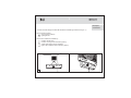
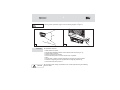
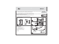
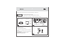
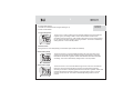
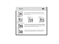
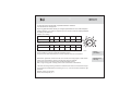
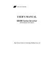
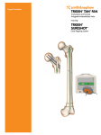
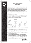
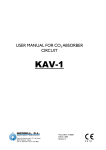
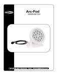
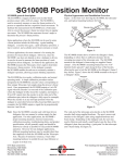
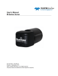
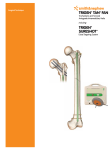
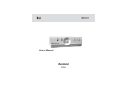
BU
User’s Manual
2009
2
CONTENTS
BU
1. Functions
p. 3
2. Circuit symbols
p. 3
3. Package
p. 4
4. Specifications
p. 4
5. Operating conditions
p. 4
6. Safety requirements
p. 4
7. Description and structure
p. 5
8. Installation
p. 6
9. Connecting to supply network
p. 7
10. Configuring and set-up
p. 9
11. Storage precautions
p. 11
12. Manufacturer's warranty
p. 11
13. Acceptance certificatep
p. 12
14. Warranty card
p. 12
BU
3
Functions
The device is multifunctional fan control unit (further BU).
BU is used to operate mode of fans located in accommodation space (kitchen, bathroom,
bedroom...).
BU can include depending on model (tab. 1) automatic control function based on use of
moisture sensor (hygrostat), lighting sensor (photo switch), moving sensor, timer and hand
control of inner and outer switch.
Also BU provides cyclic turning the power on and off. Using switches you can set any
function mode fit to situation.
For example, in the toilet you can use lighting sensor and timer. So the fan will turn on
when somebody comes in and will keep working for 10 (for example) minutes.
VENTS BU-1-60 Õ
Circuit
symbols
Models, (tab. 1)
Maximum power capacity, W
Phase's number in supply network: 1
Device type: BU - control unit
Table 1. Models
model
VENTS BU-1-60 TF
VENTS BU-1-60 THF
VENTS BU-1-60 THPF
VENTS BU-1-60
options
switch
timer
lighting sensor
moisture sensor
moving sensor
4
Package
Specifications
Operating
conditions
Safety
requirements
!
CAUTION
NOT ALLOWED
!
CAUTION
BU
Package includes:
- control unit 1pc;
- user's manual 1 pc;
- package box 1pc.
Voltage 220-240 V, 50 Hz
Maximum capacity 60 W
Loading type inductive, active
Protection power IP34
Dimensions, less than 151x46x27 mm
Environment temperature 0°C ... +40°C
Adjust range of moisture threshold 40-100 %.
BU installing must be carried by an electrician specialist according to
existing regulations.
The ambient air must include no explosive and corrosive impurities.
Using BU out of temperature range and in the rooms with aggressive impurities in the air.
BU scheme is under voltage. Install only when voltage is off.
BU
5
Description
and structure
To reach the best design and effect BU should be installed right under the fan (pic. 1)
BU front panel includes:
moving sensor (option)
lighting sensor
BU function modes are indicated by:
red LED the fan is on;
red LED moving sensor actuation (option);
yellow LED lighting sensor actuation;
green LED moisture sensor actuation (option).
1
6
!
CAUTION
BU
Moving sensor operative range is 5 m and viewing angle is 1300(pic. 2).
130Î
5m
2
3
Installation
BU installation requires:
- to take off BU front panel;
- to choose BU installation position and to outline it with the pencil (pic. 3);
- to make holes for dowels;
- to screw screws into the dowels;
- to mount BU back panel on screws and to move it upwards;
- to fix it;
- to connect BU to supply network (read about connecting to supply network)
- to make its configuring and set-up (read about configuring and set-up);
- to mount BU front panel and fix it.
!
CAUTION
BU mounting holes' design requires BU to be moved upwards during the installing
and then fixed.
BU
7
1. Connecting to supply network must be provided with the switch with the clearance between
the contact not less than 3 mm mounted into the fixed wiring.
BU connecting depends on its model. Explore connecting scheme
(pic. 5a for model BU-1-60 and pic. 5b for models BU-1-60 TF, BU-1-60 THF, BU-1-60 THPF).
Install only when the power is off (pic. 4).
Installation should be done carefully to keep BU's electronics safe.
Connecting to
supply network
!
CAUTION
2. Connect BU supply wire to outer automatic switch.
X
S1
Scheme markings
LT
L
M
M
N
L
S1
B
220-240 V
5a
N
S2
S1
X
LT
L
M
M
N
L
220-240 V
4
5b
B
N
Scheme markings:
B - fan (pic. 6);
S1 - automatic switch (pic. 4);
S2 - outer switch (pic. 7);
X - input terminal block (pic. 6).
Recommended wire marking:
L - brown
N - blue
Scheme marking
fan's input
terminal block
6
Â
BU
8
3. Open the fan. Connect supply wire to the input terminal block. Close the fan.
!
CAUTION
Fan's connecting depends on its model.
We recommend you to explore its passport before connecting.
4. Connect BU input terminal block (pic. 8) according to connection scheme (pic. 5à or 5b).
RP2
Scheme marking
Outer switch
S2
On
12 3 4
Off
RP1
Input terminal block X
7
8
5. Configure BU for your purposes (read about
configuring and set-up).
6. Put on the front panel and fix it.
7. Turn BU on by setting the switch into ON position
(pic. 9).
If everything is done correctly, the fan starts working
in the set mode.
If the fan fails to work, please carry out its
diagnostics using this manual.
9
Function
modes switch
BU
9
To configure BU settings:
1. Choose one of the five modes using the switch (pic. 8).
Configuring
and set-up
Function modes' details.
1.1 Hygrostat (option)
ON
1
2
3
4
The fan turns on when moisture level is exceeded. Moisture level is set with RP1
regulator (pic. 8) according to table 3. Green LED indicates moisture level
exceeding and turns the fan on. After moisture level drops, the fan will be working
for the time set with RP2 regulator according to table 2. The mode is activated by
setting switches 1 and 2 into ON position.
1.2 Photo switch
Turning the fan on and off depending on illumination (two modes are available):
Photo switch (dark)
The fan is turned on in 5 seconds after the light in the room turns OFF. Fan's
working time is set with the RP2 regulator according to the table 2. Operating
threshold is set with RP1 regulator. Yellow LED indicates illumination threshold
exceeding. The mode is activated by setting switch 1 into ON position.
ON
1
2
3
4
Photo switch (light)
ON
1
2
3
4
The fan is turned on in 10 seconds after the light in the room turns ON. After the
light turns off, the fan keeps working for the time set with the RP2 regulator
according to the table 2. Operating threshold is set with RP1 regulator. Yellow LED
indicates illumination threshold exceeding. If the light stays turned on over 60
minutes, the fan turns off. The mode is activated by setting switch 2 into On
position.
BU
10
1.3 Outer signal control
The fan is turned on in 3 seconds with the inner or outer switch. After being
turned on it keeps working for the time set with RP2 regulator. The mode is
activated y setting switch 3 into On position and can be combined with hygrostat
and photo switch modes.
ON
1
2
3
4
Combining with
photo switch mode (dark)
Combining with
hygrostat mode
ON
1
ON
2
3
4
1
Combining with
photo switch mode (light)
ON
2
3
4
1
2
3
4
1.4 Moving sensor (option)
ON
1
2
3
4
The fan is turned on after detecting movement of rather big object (for example
human) in the sensor's operating range. Sensor's operating range is limited with
5 m distance and 130º viewing angle. After the movement ends the fan keeps
working for the time set with RP2 regulator according to the table 2. The mode is
activated by setting switches 3 and 4 into On position.
1.5 Cyclic
ON
1
The fan is turned on periodically. It keeps working for the time set with RP2
switch and stays still for the time set with RP1 switch according to the table 2.
The mode is activated by setting switches 1, 2, 3 and 4 into Off position.
2
3
4
BU
11
2. Carry BU set-up with the help of potentiometers RP1 and RP2.
Use screwdriver for this purpose.
By turning potentiometer's handle you configure parameters from the mode description.
Setting handle on one of the six segments you can choose a value of needed parameter
according to the table 2, 3.
Table 2. Time settings
3
4
Position
1
2
3
4
5
6
Time
5 sec.
5 sec.
10 sec.
15 sec.
20 sec.
30 sec.
2
5
3
4
5
6
1
6
Table 3. Moisture settings (option)
Position
Moisture
1
2
40...50 % 50...60 % 60...70 % 70...80 % 80...90 % 90...100 %
Keep BU in manufacturer's package in ventilated room under the temperature +5ºC - +40ºC
and air humidity not over 60% (under the temperature +20ºC).
The presence of acids, alkalis and other corrosive impurities in the air is not allowed.
Storage
precautions
Manufacturer guaranties normal work of BU for 12 months from being bought in retail network
if all the rules of transporting, keeping, mounting and using were followed.
The warranty doesn't cover devices with mechanical damage features.
With no sign of buying date, warranty period counts from the date of manufacture.
Manufacturer's
warranty
If BU work fails during warranty period and it's manufacturer's fault, the customer has the right
to change BU at the Manufacturer's according to art. 14 p. 9 of “The law about customers' right
protection”.
Warranty service and exchange:
01030, Kiev, Kotsubynsky st., 1
BU
12
!
CAUTION
Acceptance
certificate
MANUFACTURER isn't responsible for the damage appeared after BU misuse or in
the result of rude mechanical invasion.
BU owner must follow the manual.
Fan control unit “BU-1-60_________________”
corresponds
TU U 30637114-001-2000 and fits for operation
Inspector's stamp
Date of manufacture
Seller
Name of the shop, seller's stamp
Selling date
Warranty
card
V24EN-03