1
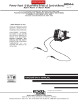
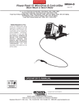
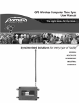
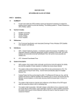
Wireless Tone Generator User Manual
Synchronised Solutions for every type of facility
SCHOOLS
HEALTHCARE
GOVERNMENT
INDUSTRIAL
CORPORATE
CONTENT
Precautions . . . . . . . . . . . . . . . . . . . . . . . . . . . . . . . . . . . . . . . . . . . . . . . . . . . . . . . . . . . . . . . . . . . . . . . . . 4
Safety Precautions . . . . . . . . . . . . . . . . . . . . . . . . . . . . . . . . . . . . . . . . . . . . . . . . . . . . . . . . . . . . . . . 4
Equipment Precautions . . . . . . . . . . . . . . . . . . . . . . . . . . . . . . . . . . . . . . . . . . . . . . . . . . . . . . . . . . . . 4
Declaration of Conformity . . . . . . . . . . . . . . . . . . . . . . . . . . . . . . . . . . . . . . . . . . . . . . . . . . . . . . . . . . . . . 5
Product Description . . . . . . . . . . . . . . . . . . . . . . . . . . . . . . . . . . . . . . . . . . . . . . . . . . . . . . . . . . . . . . . . . . 6
System Components . . . . . . . . . . . . . . . . . . . . . . . . . . . . . . . . . . . . . . . . . . . . . . . . . . . . . . . . . . . . . . . . . 6
Wireless Tone Generator Unit . . . . . . . . . . . . . . . . . . . . . . . . . . . . . . . . . . . . . . . . . . . . . . . . . . . . . . . 5
Primex Wireless Event Scheduler Pro Software . . . . . . . . . . . . . . . . . . . . . . . . . . . . . . . . . . . . . . . . 5
Transmitter . . . . . . . . . . . . . . . . . . . . . . . . . . . . . . . . . . . . . . . . . . . . . . . . . . . . . . . . . . . . . . . . . . . . . 5
Other Parts . . . . . . . . . . . . . . . . . . . . . . . . . . . . . . . . . . . . . . . . . . . . . . . . . . . . . . . . . . . . . . . . . . . . . 5
Feature Overview . . . . . . . . . . . . . . . . . . . . . . . . . . . . . . . . . . . . . . . . . . . . . . . . . . . . . . . . . . . . . . . . . . . . 7
Switch IDs . . . . . . . . . . . . . . . . . . . . . . . . . . . . . . . . . . . . . . . . . . . . . . . . . . . . . . . . . . . . . . . . . . . . . . 7
Channel Number Switch . . . . . . . . . . . . . . . . . . . . . . . . . . . . . . . . . . . . . . . . . . . . . . . . . . . . . . . . . . . 7
Tone Volume Dial . . . . . . . . . . . . . . . . . . . . . . . . . . . . . . . . . . . . . . . . . . . . . . . . . . . . . . . . . . . . . . . . 7
Test Button . . . . . . . . . . . . . . . . . . . . . . . . . . . . . . . . . . . . . . . . . . . . . . . . . . . . . . . . . . . . . . . . . . . . . 7
Signal Indicator . . . . . . . . . . . . . . . . . . . . . . . . . . . . . . . . . . . . . . . . . . . . . . . . . . . . . . . . . . . . . . . . . . 7
Audio Output Jack . . . . . . . . . . . . . . . . . . . . . . . . . . . . . . . . . . . . . . . . . . . . . . . . . . . . . . . . . . . . . . . 7
Access Covers . . . . . . . . . . . . . . . . . . . . . . . . . . . . . . . . . . . . . . . . . . . . . . . . . . . . . . . . . . . . . . . . . . 7
Relay Output Terminals . . . . . . . . . . . . . . . . . . . . . . . . . . . . . . . . . . . . . . . . . . . . . . . . . . . . . . . . . . . . 7
Hardware Setup . . . . . . . . . . . . . . . . . . . . . . . . . . . . . . . . . . . . . . . . . . . . . . . . . . . . . . . . . . . . . . . . . . . . . 7
Prerequisites . . . . . . . . . . . . . . . . . . . . . . . . . . . . . . . . . . . . . . . . . . . . . . . . . . . . . . . . . . . . . . . . . . . . 7
Location of the Wireless Tone Generator . . . . . . . . . . . . . . . . . . . . . . . . . . . . . . . . . . . . . . . . . . . . . . . . 8
Setting Switch Preferences . . . . . . . . . . . . . . . . . . . . . . . . . . . . . . . . . . . . . . . . . . . . . . . . . . . . . . . . . . . . 8
Set Channel Number . . . . . . . . . . . . . . . . . . . . . . . . . . . . . . . . . . . . . . . . . . . . . . . . . . . . . . . . . . . . . 9
Switch Setting for Multiple Transmitters . . . . . . . . . . . . . . . . . . . . . . . . . . . . . . . . . . . . . . . . . . . . . . . 9
Set Switch ID . . . . . . . . . . . . . . . . . . . . . . . . . . . . . . . . . . . . . . . . . . . . . . . . . . . . . . . . . . . . . . . . . . . 9
Determining the Correct Switch ID . . . . . . . . . . . . . . . . . . . . . . . . . . . . . . . . . . . . . . . . . . . . . . . . . . . 9
Set Dip Switches . . . . . . . . . . . . . . . . . . . . . . . . . . . . . . . . . . . . . . . . . . . . . . . . . . . . . . . . . . . . . . . . . 9
Connecting to Your PA and/or Bell System . . . . . . . . . . . . . . . . . . . . . . . . . . . . . . . . . . . . . . . . . . . . . . 10
Audio Output . . . . . . . . . . . . . . . . . . . . . . . . . . . . . . . . . . . . . . . . . . . . . . . . . . . . . . . . . . . . . . . . . . . 10
Relay Output . . . . . . . . . . . . . . . . . . . . . . . . . . . . . . . . . . . . . . . . . . . . . . . . . . . . . . . . . . . . . . . . . . . 11
Attach Antenna . . . . . . . . . . . . . . . . . . . . . . . . . . . . . . . . . . . . . . . . . . . . . . . . . . . . . . . . . . . . . . . . . 11
Connect Power . . . . . . . . . . . . . . . . . . . . . . . . . . . . . . . . . . . . . . . . . . . . . . . . . . . . . . . . . . . . . . . . . 11
Test Button . . . . . . . . . . . . . . . . . . . . . . . . . . . . . . . . . . . . . . . . . . . . . . . . . . . . . . . . . . . . . . . . . . . . 11
Securing the Wireless Tone Generator . . . . . . . . . . . . . . . . . . . . . . . . . . . . . . . . . . . . . . . . . . . . . . . 12
Software Setup . . . . . . . . . . . . . . . . . . . . . . . . . . . . . . . . . . . . . . . . . . . . . . . . . . . . . . . . . . . . . . . . . . . . . 12
Updating the Tone Schedule . . . . . . . . . . . . . . . . . . . . . . . . . . . . . . . . . . . . . . . . . . . . . . . . . . . . . . . . . . 12
Troubleshooting . . . . . . . . . . . . . . . . . . . . . . . . . . . . . . . . . . . . . . . . . . . . . . . . . . . . . . . . . . . . . . . . . . . . 12
Power Failure . . . . . . . . . . . . . . . . . . . . . . . . . . . . . . . . . . . . . . . . . . . . . . . . . . . . . . . . . . . . . . . . . . 12
Transmitter Loses Power But The Wireless Tone Generator Does Not . . . . . . . . . . . . . . . . . . . . . . 13
Wireless Tone Generator Loses Power But The Transmitter Does Not . . . . . . . . . . . . . . . . . . . . . . 13
Wireless Tone Generator And The Transmitter Lose Power . . . . . . . . . . . . . . . . . . . . . . . . . . . . . . 13
Tones Not Occurring As Expected . . . . . . . . . . . . . . . . . . . . . . . . . . . . . . . . . . . . . . . . . . . . . . . . . . 13
If The Green Light Is On But Not Flashing . . . . . . . . . . . . . . . . . . . . . . . . . . . . . . . . . . . . . . . . . . . . 13
If The Green Light Is Flashing, But The Wireless Tone Generator Is Not Operating . . . . . . . . . . . . 13
Specifications . . . . . . . . . . . . . . . . . . . . . . . . . . . . . . . . . . . . . . . . . . . . . . . . . . . . . . . . . . . . . . . . . . . . . .13
Typical Applications . . . . . . . . . . . . . . . . . . . . . . . . . . . . . . . . . . . . . . . . . . . . . . . . . . . . . . . . . . . . . . . . .15
-3-
Precautions
Safety Precautions
Warning: The Wireless Tone Generator must be installed by a qualified electrician who
understands the paging or intercom system with which the Wireless Tone
Generator is interfacing. The installer must also know and adhere to the local
codes and regulations.
Warning: The Transmitter and the Wireless Tone Generator are designed for indoor
use only and they are not weather protected.
Warning: Operating the Transmitter or Wireless Tone Generator outdoors during
adverse weather conditions is an electrical hazard and may damage the
devices and nullifies the warranty.
Warning: It is recommended that standard acceptance procedures be followed prior to
operating this equipment in the proximity of life support systems.
Equipment Precautions
Warning: Disconnect power from the Wireless Tone Generator before removing either
cover and do not reconnect power until both covers are secured. Do not make
any adjustments or connections while power is supplied to the unit. Except
during setup, the larger cover should remain closed and secure.
Warning: No servicable in the equipment
Warning: In order to turn the transmitter off, unplug the power supply unit from the wall.
The transmitter must be placed within the vicinity of a wall outlet.
-4-
Declaration of Conformity
We,
Primex Wireless, Inc.
Of
965 Wells Street
Lake Geneva, WI 53147
U.S.A.
declare under our sole responsibility that the product
The primex Wireless Synchronised Time System including the FM68 Radio Transmitter, the OFM
12.5AC-03 Optic Clock, the KRS-TRS-009-01 Bell Receiver, the KRS-XXS-009-01 Repeater, the
KRS-XXS-009-02 Network Receiver, the 2.5” x 4 digit LED Digital Clock, the 2.5” x 6 digit LED
Digital Clock, the 2.5” x 4 digit Dual LED Digital Clock, the 4” x 4 digit LED Digital Clock, the 4” x 6
digit LED Digital Clock, and the 4” x 4 digit Dual LED Digital Clock
to which this declaration relates, is in conformity with the following standards and/or other
normative documents.
ETS EN 300 220-3
ETS EN 301 489-3
EN 61010
We herby declare that [all essential radio test suites have been carried out and that] the
above named product is in conformity to all the essential requirement of Directive 199/5/EC.
The conformity assessment producer referred to in Article 10 and detailed in Annex [II] Of Directive
1999/5/EC has been followed.
The equipment will also carry the class identifier:
The technical documentation relevant to the above equipment will be held at:
Primex Wireless, Ltd.
Unit G420
Dean Clough
Halifax
West Yorkshire
HX3 5AX
Phone: 0800-3896996
-5-
Product Description
The Wireless Tone Generator receives wireless time signals from the Primex Wireless Transmitter and it produces a tone over an existing PA system and/or initiates bells the bells at precise scheduled times. The
Wireless Tone Generator is designed to interface and be compatible with most available PA or bell systems.
A precise schedule of the tones is created with the Event Scheduler Pro software programme using a
Windows-based PC. Once the schedule is developed, it is downloaded from the PC to the Transmitter. The
schedule is stored in the Transmitterʼs memory and can be easily changed in the future by using the software. By dedicating a computer to the transmitter and using remote access software you are able to remotely download bell schedules into the Transmitter from the convenience of your own computer.
This manual details the installation and operation of the Wireless Tone Generator hardware unit. Instructions
on installing and using the Event Scheduler Pro software programme can be found in the Event Scheduler
Pro Manual. For information on the Transmitter, see the GPS Wireless Clock System User Manual.
System Components
Wireless Tone Generator Unit
The Wireless Tone Generator unit receives precise time signals from the transmitter then,
according to its software programming, provides either N/O or N/C dry
contacts for bell system operation or a low impedance audio tone output
Switch ID #
for a PA system.
Antenna
Primex Wireless Event Scheduler Pro Software
This software programme runs on a Windows-based PC and is used to
set the precise schedule of the tones. The programme comes on a CDROM and must be installed onto the PC before the Transmitter can be
used (see the Event Scheduler Pro Manual). Once the schedule is
developed, it is downloaded from the PC to the Transmitter. The schedule is stored in the Transmitterʼ s memory and can be easily changed in
the future by using the software.
Channel
Number
Transmitter
The Transmitter continuously broadcasts the precise time to the Wireless Tone Generator. The Transmitter
operates on OFCOM licenced FM frequencies that have good building penetration and are regulated to minimize interference on the selected channel. The Transmitter also stores the tone schedule in its non-volatile
memory and broadcasts it to the Wireless Tone Generator.
Other Wireless Tone Generator Parts:
• Antenna
• DB9 Computer Cable
• Power Supply
• Audio Patch Cable
• 3-Spade Audio Patch Cable
If for any reason any of the above parts are missing or damaged please contact Primex Wireless
at 0800-3896996.
-6-
Feature Overview
Switch IDʼs
Switch IDʼs set the identification code for the Wireless Tone Generator (0-99). Only the first 25 IDs are valid
(0-24)
Channel Number Switch
This must be set to the same channel number that the Transmitter is broadcasting the schedule from.
Tone Volume Dial
Controls the volume of the tone. Rotating the volume knob to the right (clockwise) increases the loudness of
the tone. Rotating the volume knob to the left (counter-clockwise) decreases the loudness of the tone. The
Wireless Tone Generator volume control is factory preset at 25%.
Note: It is recommended that if the tone is not loud enough, the volume control first be adjusted on the
external system.
Test Button
Confirms the proper installation of the Wireless Tone Generator. Holding down the test button will generate a
tone to the connected PA system and initiates power to the bell systems that are correctly connected. In an
emergency, the tone/bell test button can be used to generate a tone/bell at any given time.
Signal Indicator
A green LED will flash each time a transmitted signal is received by the Wireless Tone Generator from the
Transmitter. It will flash once a second if it is receiving a good signal.
Audio Output Jack
The audio output jack connects via a cable to the audio input jack on the PA system to transmit the tone signal.
Access Covers
The Wireless Tone Generator has two access covers. The smaller cover is for access to relay terminals. The
larger cover is only for access to the electronics of the Wireless Tone Generator, including the dip switches.
Except during initial setup, the larger cover should remain closed and secure.
Relay Output Terminals
The two relay output terminals, one normally open and the other normally closed, provide a relay output connection to a PA and/or bell system.
Hardware Setup
Prerequisites
Note: In areas that requires multiple schedules and/or different schedules, you may require multiple
Wireless Tone Generators. When programming schedules, make sure you use different Switch ID
numbers for each different schedule. Set the corresponding Wireless Tone Generator to the
matching Switch ID number. If your installation requires multiple transmitters, make sure that each
transmitter has the bell or tone schedule downloaded into it.
Call Primex Wireless tech support at 0800-3896996 for details on setting up a multiple Wireless Tone
Generator installation.
-7-
Warning: The Wireless Tone Generator must be installed by a qualified electrician who
understands the paging or bell system with which the Wireless Tone Generator
is interfacing. The installer must also know and adhere to the local codes and
regulations.
Before you begin installation, check the following:
1. A Primex Wireless Transmitter with GPS receiver must be set up and operating to ensure proper
installation. For Transmitter details see the GPS Wireless Clock System User Manual.
2. A PA system and or electro-mechanical bell system must be installed.
Note: It is not necessary to set up the Event Scheduler Pro software at the time of installation of the
Wireless Tone Generator. The Event Scheduler Pro can be added at a later time to complete the
functionality of the system.
Location of the Wireless Tone Generator
The Wireless Tone Generator can be located anywhere within transmission range of the Transmitter, in a
place that is convenient for connection to the PA and/or bell system. Normally, the Wireless Tone Generator
would be within close proximity (within 8 feet) of the PA system. For PA amplifiers that have a balanced input
the Wireless Tone Generator can be located at greater distances (50 feet) from the PA amplifier. For amplifiers that do not have a balanced input increasing the distance beyond 8 feet is not recommended. For best
reception the antenna should point vertically with respect to the ground.
Setting Switch Preferences
Warning: Disconnect power from the Wireless Tone Generator before removing either
cover and do not reconnect power until both covers are secured. Do not make
any adjustments or connections while power is supplied to the unit. Except during
setup, the larger cover should remain closed and secure.
The Wireless Tone Generator has several user-adjustable switches that control a particular function:
• Channel # (external switches)
• Switch ID (external switches)
• Automatic Channel Scanning (PCB only/Switch #4)
• British Summer Time (PCB only/Switch #5 )
• Switch Defined Closure (PCB only/Switches 6, 7, 8)
Be sure that all switch settings are correct to ensure the proper functioning of the Wireless Tone Generator.
-8-
All Wireless Tone Generators are factory preset to the following:
• Channel set to ”1”
• Switch ID set to “00”
• Volume Control set to “25%”
IMPORTANT NOTE: If these factory presets meet your needs for setup then you do not
need to make any adjustments to the switches.
Set Channel Number
The Wireless Tone Generator must be set to receive the same channel being broadcast by the Transmitter.
The channel number setting for the Transmitter can be found on its front display in the lower right hand corner (For details, see the GPS Wireless Clock System User Manual).
Set the Wireless Tone Generator to operate on the same channel as the Transmitter by using the channel
number rotary switch located on the front of the Wireless Tone Generator (see above figure). If you are using
multiple Transmitters, see “Switch Setting for Multiple Transmitters” section.
Warning: Only set the channel on the Transmitter to the frequency specified on the
OFCOM licence.
Note: The Wireless Tone Generator is factory preset to Channel 1. If the Transmitter is operating on
Channel 1 you do not need to change the channel setting on the Wireless Tone Generator.
If the Transmitter is not set to Channel 1, set the channel switch on Wireless Tone Generator to the
corresponding channel.
Switch Setting for Multiple Transmitters
If your site is using multiple Transmitters operating on different channels, you may set your Wireless Tone
Generators to receive transmissions from any Transmitter within range by selecting “automatic channel
scanning”. Activate the automatic channel scanning by setting dip switch #4 to the OFF position.
Note: Cycle power for this change to take effect. See “Set Dip Switches” for more information.
Warning: The same schedule must still be downloaded into every Transmitter if you activate automatic
channel scanning. If you have different schedules, you will need to set the channel number
on the Wireless Tone Generator to the specific Transmitter that you have downloaded that
particular schedule into.
Set Switch ID (See Figure on page 9.)
The Switch ID corresponds to the zone to which the Wireless Tone Generator is assigned. It is set by using
the two red knobs labeled "Switch ID" at the top of the Wireless Tone Generator. The Switch ID is a two-digit
number with the left knob setting the first digit and the right knob setting the second digit. For example, to set
the Switch ID to 05, set the left rotary switch to 0 and the right rotary switch to 5. To set the Switch ID to 23,
set the left rotary switch to 2 and the right rotary switch to 3, etc.
Determining the Correct Switch ID:
The Switch ID must match the schedule ID specified in the Event Scheduler Pro. There are twenty five allowable IDʼs from 00 to 24. Use 01 for the first Wireless Tone Generator.
-9-
Note: If your application needs only one Wireless Tone Generator then you need only one zone. If you
require multiple Wireless Tone Generators, each one must be assigned a different Switch ID and
different zones must be set up in the Event Scheduler Pro. See the Event Scheduler Pro Software
Manual for further details.
Set Dip Switches
The dip switches select options for automatic British Summer Time Adjustments, Automatic Channel
Scanning, and Switch Defined Closure Event Types.
To access the dip switches you must remove the smaller access cover and then the larger access cover.
The figure on page 14 shows the location. To change a dip switch setting, carefully move the switch between
settings.
• For British Summer Time (BST) bypass, set switch #5 to the “ON” position.
• For Automatic Channel Scanning (RF scan), set switch #4 to the “OFF” position.
• For Switch Defined Closure Event Types, see the Switch Defined Closure Table in this manual (see
page 14).
Note: Cycle power for this change to take effect.
Connecting to PA and/or Bell System
Warning: Only use local code approved methods to connect the Wireless Tone Generator
to your PA and/or bell system.
The Wireless Tone Generator must be physically connected to your PA and/or bell system in order to function.
Note: In installations with multiple Wireless Tone Generators, any unit may be used for the tone output
via the “audio output”, or for switching via the “contacts”. In some installations, you may choose to
use both outputs (audio and switching) to satisfy your needs. For assistance, call Primex Technical
Support at 0800-3896996.
Audio Output
The Wireless Tone Generator has an isolated transformer output. Primex supplies two styles of audio cables.
One is for amplifiers with a terminal block and the other is for the standard RCAtm type audio input.
Using the appropriate cable, connect the audio output port from the Wireless Tone Generator to the audio
input port on the PA system. Refer to the installation manual of your PA system for instructions on where to
connect the output. Locate the correct connection points on the existing PA system that provides the desirable result for the Wireless Tone Generator supplied tone.
USING AUDIO
PATCH CABLE
USING 3-SPADE
AUDIO PATCH CABLE
P.A. RECEIVER BACK
P.A. RECEIVER BACK
P.A. RECEIVER BACK
WIRELESS TONE
GENERATOR
WIRELESS TONE
GENERATOR
WIRELESS TONE
GENERATOR
USING BOTH AUDIO OUTPUT
AND RELAY OUTPUT
BELL
RELAY
AS
NEEDED
AUDIO
VOLUME
TO CONNECTION POINTS
WITHIN P.A. RECEIVER
9VDC
AUDIO
VOLUME
9VDC
AUDIO
9VDC
VOLUME
TO AUDIO INPUT
NO or NC
TO AUDIO OUTPUT
TO AUDIO OUTPUT
TO AUDIO OUTPUT
-10-
TO AUDIO INPUT
Relay Output
Warning: When connecting to the Relay Output terminals, the larger cover should remain
closed and secure. Only the smaller cover should be open.
Warning: Remain within safe operating limits of the relay specification at all times. 4.4A
250VAC Max.
If desired, connect the relay output to the devices to be controlled by the Wireless Tone Generator. You can
connect to either the normally open or normally closed relay cycle.
There are two relay output terminals on the Wireless Tone Generator under the small cover. The left two
screws are the “normally open” terminal, labelled "NO." The right two screws are the “normally closed” terminal, labeled "NC." The relay of the Wireless Tone Generator opens and closes to reflect the action programmed and stored in the non-volatile memory of this Wireless Tone Generator.
Attach Antenna
Attach the antenna to the Wireless Tone Generator. Operating without the antenna being properly connected
will greatly reduce operating range, but will not harm it.
Connect Power
Warning: Re-attach the covers on the Wireless Tone Generator and secure them before
connecting power to the unit. Do not plug in the power transformer until after
the covers have been secured.
Once the Wireless Tone Generator has been connected to a PA and/or bell system and the covers have been
secured you can connect it to electrical power. Plug the Wireless Tone Generator power transformer into a
full time 220-240 volt outlet, then into the power input receptacle on the bottom of the Wireless Tone
Generator case. The power input is labeled "9 VDC."
Warning: Use only the power transformer supplied by Primex.
The green LED should begin to flash when the Wireless Tone Generator is receiving a signal
from the Transmitter. This generally takes approximately 20 seconds. If the green light is not
flashing, see the Troubleshooting section of this manual.
Test Button
Confirm the proper installation and operation of the Wireless Tone Generator by using the test
button on the front of the Tone Generator. To initiate the tone, press down and hold the test
button until the tone is heard. Once released, the test button tone will stop.
The test button can also confirm that the Wireless Tone Generator is
receiving a good signal. Pushing and immediately releasing the test
button activates the "beep function." When the Wireless Tone Generator
is receiving a valid time signal from the Transmitter it will beep
continuously for one minute.
The Wireless Tone Generator needs a signal from the Transmitter to give
it time information as well as event information. If it is located in a
marginal reception area, it will still function as long as it receives the
information that it needs initially. If it does not receive again, assuming
-11-
Antenna
Switch ID #
Channel
Number
that the power has not been interrupted, it will "free run" on its own clock and will continue to operate on its
memoryʼs current event information. Keep in mind that larger schedules take longer to send from the
Transmitter to the Wireless Tone Generator.
Note: This download may take 30 or more seconds to complete.
You can adjust the volume of the tone using the volume dial on the bottom of the Wireless Tone Generator
case. Note: The Wireless Tone Generator volume control is factory preset at 25%. Rotating the volume knob
to the right (clockwise) increases the loudness of the tone. Rotating the volume knob to the left (counterclockwise) decreases the loudness of the tone.
Securing the Wireless Tone Generator
It is important to secure the Wireless Tone Generator base to a solid object to protect it from damage and
ensure its continued functioning. The base has four tabs where it can be screwed onto any solid surface.
Hardware setup of the Wireless Tone Generator is now complete. Once the Scheduler Software has been
installed and set up, the Wireless Tone Generator will be fully functional.
Software Setup
The tone schedule of the Wireless Tone Generator is set using the Event Scheduler Pro Software. This software must be loaded into a PC computer and the desired schedule must be entered into the software programme. See the Event Scheduler Pro Manual for detailed instructions on installing and using the application.
After the software has been installed and the schedule entered into the software, the schedule must be
downloaded from your computer into the Transmitter using the supplied DB9 connector cable. Once the
download is complete, remove the DB9 connector cable from the Transmitter and the computer.
Updating the Tone Schedule
To change the tone schedule, enter the new schedule into the Event Scheduler Pro software programme,
then upload the new schedule into the Transmitter. See the Event Scheduler Pro Software User Manual for
detailed instructions. Once the new schedule has been downloaded into the Transmitter, the updated programme is immediately transmitted to the Wireless Tone Generator from the Transmitter. The Wireless Tone
Generator operation will reflect the updated programme from the time it receives the updated programme
data. This may take up to 20 minutes.
Troubleshooting
Power Failure
The Wireless Tone Generator does not need to be manually reset after power failure.
Note: It is highly recommended that both the Transmitter and the Wireless Tone Generator are plugged
into a UPS backup.
-12-
Transmitter Loses Power But The Wireless Tone Generator Does Not
The Wireless Tone Generator will continue normal operation using its own internal clock. On restoration of
power to the Transmitter, the Transmitter will look for a time signal from the GPS Receiver and on reception
of the GPS time signal, the Transmitter will begin transmission. In this situation, the Wireless Tone Generator
continues to function normally, but its timekeeping may drift slightly up to 1 second per day while the
Transmitter is off.
Wireless Tone Generator Loses Power But The Transmitter Does Not
The Wireless Tone Generator will not function until power is restored and it has received a valid time signal
from the Transmitter. Since the programme information is stored in the Wireless Tone Generator's nonvolatile memory, it only needs to receive the time from the Transmitter to resume proper operation. In this situation, the Wireless Tone Generator will start proper operation within a few seconds after power is restored.
Wireless Tone Generator And The Transmitter Lose Power
The Wireless Tone Generator will not function until power is restored to both, and the Transmitter has
received a valid time signal from the GPS Receiver. In this situation, it should take from one minute to two
minutes under good GPS signal reception; however, under poor signal reception conditions it may take
longer.
Tones Not Occurring As Expected
If tones are not occurring as expected, follow the steps below to determine the problem and solution.
If The Green Light Is On But Not Flashing:
1. This means the Wireless Tone Generator is not receiving a signal from the Transmitter (this process
takes approximately 20 seconds.)
2. Verify power by confirming green LED is lit on front of Tone Generator.
3. Check that the Transmitter is operating properly. For details on troubleshooting the Transmitter, refer to
The GPS Wireless Clock System Manual.
4. If the Transmitter is operating properly, then something may be interfering with the signal or reducing
the signal range. This could be the result of localised interference that can be corrected by adjusting
the location of the Wireless Tone Generator. Move the Wireless Tone Generator around in close proximity of the original installation site until a good signal is verified by the flashing green light. Find an
appropriate location where there is both a strong signal (green LED flashes once per second) and a
convenient place for the Wireless Tone Generator to be secured.
5. Secure the Wireless Tone Generator at the new location and verify that the new antenna placement is
getting the signal. Verify this by confirming that the green LED is flashing on the front of the Tone
Generator.
6. If the new location is not getting the signal, try another location by repeating the use of the Test Button
on the Wireless Tone Generator.
If The Green Light Is Flashing, But The Wireless Tone Generator Is Not Operating:
1. Check the proper operation of the Transmitter by referring to the GPS Wireless Clock System User
Manual.
2. Verify that the channel set on the Wireless Tone Generator coincides with the channel being used by
the Transmitter. If different, correct the switch settings on the Wireless Tone Generator.
-13-
3. Verify that the Switch ID agrees with the zone specified in the Event Scheduler Pro software programme. Verify that the Event Scheduler Pro software programme in the Transmitter is using the correct zone and if not, modify the programme or the Wireless Tone Generator Switch ID setting as necessary to correct the zone. See the Event Scheduler Pro Software User Manual for details.
4. Check the connection points for the wiring between the Wireless Tone Generator and the PA and/or
bell systems.
5. If the Wireless Tone Generator seems to be operating properly, but no announcement is being heard
over the PA system or the bells are not functioning properly, check out the operation of the PA system
or bell system and correct the problem. Verify that the PA and/or bell system is working correctly for
other functions not controlled by the Wireless Tone Generator. Refer to your PA and/or bell system
manual for troubleshooting details.
6. Check the green indicator light again to verify that the Wireless Tone Generator is receiving an
acceptable signal.
7. If after going through the above troubleshooting steps the Wireless Tone Generator is still not
operating, call technical support at 0800-3896996.
Switch Defined Closure 1 Table
SWITCH 6
ON
OFF
ON
OFF
OFF
ON
ON
OFF
SWITCH 7
ON
ON
OFF
OFF
ON
ON
OFF
OFF
SWITCH 8
ON
ON
ON
ON
OFF
OFF
OFF
OFF
CLOSURE
100 ms
250 ms
375 ms
400 ms
8s Delayed**
14s Delayed**
10s
7s
**These events will occur at the end of the scheduled minute. It is also
required that at least 1 minute is left between events using either of the
delayed switches defined in closure events.
All switch settings for switch defined closure 2 produce a 100ms closure.
Specifications
Power Source = 220-240 VAC to connect the 9 volt switching power supply to Wireless Tone Generator
(6 ft. cord on power supply)
Switching Contacts = ''Form D'' (one set each) normally open and normally closed
Switch Ratings
1. Contact Ratings:
a. 4.4 amp 1/6HP 125, 250AC
b. 4.4 amp. 20 VDC
2. C Break Ratings
a. 30 Watt Maximum
b. 1 amp. 30 VDC; 24 amp. 125 VDC
-14-
Audio Output
1. Isolation transformer with centre tap 600/150 ohms output impedance
2. Variable output and line level
Switch Identification Codes = 25
Selectable Channels = 4 (plus Automatic Channel Search)
programmable Events = 96 with 7-day selectable operations
Selectable Options For Each Event
• None
• Tone on for 1 second
• Tone on for 2 seconds
• Tone on for 3 seconds
• Tone on for 5 seconds
• Tone on indefinitely
• Tone off indefinitely
• Tone on for 2 seconds, off for 1 second, on for 2 seconds, off
• Tone on for 1 second, off for 1 second, repeated 5 times.
• Switch defined closure*
• Switch defined closure 1 : 100 ms, 25O ms, 375 ms, 8s delayed **, 14s delayed **, 10s, 7s,
• Switch defined closure 2 : 100 ms
* Switch defined closure events are used to accommodate Master Clock updates and with relay
closures only. They are configured with dip switches inside the Wireless Tone Generator.
** These events occur at the end of the scheduled minute. It is also required that at least 1 minute is
left between events using either of the delayed switch defined closure events.
Typical Applications for the Primex Wireless Tone Generator (WTG)
Disclaimer: This section describes how to use the Wireless Tone Generator to control equipment in
customer’s facilities that are produced and serviced by companies other than Primex Wireless. It is
recommended that all necessary wiring be performed by a qualified electrician who has knowledge of
the equipment the WTG is being interfaced with.
1. Bell/Tone Configuration
The Wireless Tone Generator most common application is in schools. There it is used to activate the bells
or tones that denote the beginning or end of class periods according to a pre-programmed schedule. In
tone configurations (Fig. 1), the Wireless Tone Generator produces a line-level tone that is accessible via a
mini-jack which can be amplified and distributed throughout the facility using the school’s existing PA system. Below is a simple diagram showing tone configuration:
-15-
In addition, there are three other ways to use the Wireless Tone Generator to synchronise bells or tones to
the Primex Wireless GPS Clock System. See Fig. 4 for bell configuration. Alternate uses are outlined on the
next page:
2. Master Clock Synchronisation (Applicable Systems)
Some facilities that install the Primex Wireless Clock System may already have an existing bell/tone
scheduling system installed and do not want to use our scheduling software but want to replace their
existing clocks with clocks from Primex Wireless. In this type of set-up, the Wireless Tone Generator
could possibly be used to synchronise the existing scheduler to the new clocks. This will make the bell or
tone events occur in sync with the Primex Wireless Clock System.
All types of bell scheduler equipment utilize some sort of master clock to coordinate the timing of the
annunciated events. The ability of the Wireless Tone Generator to synchronise a master clock depends on
whether the master clock was designed to accept an external synchronisation by switched contacts. If this
external sync feature does exist, there might be two screw terminals labelled. Possible labels could be;
“Ext. Sync” or “reset” on the rear panel of the equipment, or possibly on the circuit board inside the unit.
(See Fig. 2)
Some master clocks are pre-programmed to reset to a specific time, for example at 2:00 AM, when these
terminals are briefly shorted together the master clock is updated. The master is updated to correct any
minor drift that occurred in the past 24 hours. Some systems give the service technician the option to programme the time the master clock will change to when the terminals are shorted. In either case, the
Wireless Tone Generator can be programmed to provide a normally open (NO) or normally closed (NC) relay
contact closure at precise times as needed to perform the synchronisation, also called a “time update”.
Time updates are generally scheduled to occur once per day. The amount of time drift in a 24-hour period
depends on the accuracy of the master clock.
Contact your system’s service provider to see if the time update feature is available.
-16-
3. Synchronised Bell/Tones, or “All Call”
If a master clock cannot be updated via the Wireless Tone Generator, another method of synchronising bells
and tones to the Primex Wireless GPS Clocks is to use the Wireless Tone Generator to activate the “manual
test” or “override” of an existing bell or tone scheduler. In this case, the bell or tone scheduler equipment
must have what is commonly referred to as an “All Call” button, or a switch that can be activated to manually
sound all the bells at once. The two wires that are switched together to activate the bells or tones must be
accessible on the scheduler equipment. These wires are connected to the Wireless Tone Generator’s normally open (NO) contacts as shown in Fig. 3 below:
4 . Outdoor Bells or Horns
Disclaimer: This section describes how to use the Wireless Tone Generator to control high voltage (220-240
Volt) devices. It is recommended that all wiring be performed by a qualified electrician.
Many facilities have outdoor bells or horns to annunciate the beginning and end of scheduled events. See
Fig. 4 for an example of the wiring between a bell or horn and the Wireless Tone Generator (indoor applications).
-17-
For outdoor installations of bells, it is necessary to mount the Wireless Tone Generator unit indoors in a temperature-controlled environment. Typically, the Wireless Tone Generator is mounted on the inside of an exterior wall and a wire pair is pulled through the wall to the bell, which is mounted outside as shown in Fig. 5
below:
OTHER APPLICATIONS FOR THE WIRELESS TONE GENERATOR
Disclaimer: This section describes how to use the Wireless Tone Generator to control devices that are outside the original intentions for which this product was designed. While these applications can be performed
contacting Primex Wireless technical support is recommended to discuss your unique application. All wiring
must be performed by a qualified electrician.
In addition to scheduling bells, the Wireless Tone Generator or the Wireless Industrial Controller can be used
for a variety of other applications, including the control of lights in a building, regulation of thermostats for
heaters and air conditioners, and the activation of alarm systems. The Wireless Tone Generator is even
capable of starting coffee pots in employee break areas at specified times.
It is imperative that the user or installer be technically qualified to determine compatibility, as the Wireless
Tone Generator is limited to switching up to 4.4 amps of current. Note that the DC rating is lower due to its
propensity to arc.
Maximum ratings for Wireless Tone Generator relay contacts:
4.4A, 1/6 hp, 125V, 250V AC
4.4A, 20 volts DC
(DC Break ratings: 30W max: 1A @ 30 VDC, .24A @ 125 VDC)
A generic control function diagram is shown in Fig. 6 below:
-18-
Controlling High Power Devices:
Sometimes it is desired to control a device that draws more than 4.4A of current. An example might be an
office building that has wall-type air conditioners that are not controlled by a low-voltage thermostat. An air
conditioner draws more than 4.4A, so it cannot be controlled directly by the Wireless Tone Generator. In order
to accomplish this, it is necessary to use the Wireless Tone Generator to control a contactor or high current
rated relay as shown in Fig. 7 below:
Phone:0800-3896996 Fax: 01422-349462
www.primexwireless.co.uk
[email protected]
Primex Wireless, Inc. ©2005, Patents Pending. Printed in the USA.
41002M
4/28/05