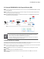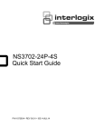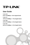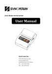
1
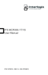
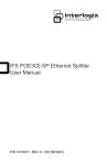
IFS POE302-EX User Manual P/N 1072690 • REV A • ISS 23OCT13 Copyright Trademarks and patents Manufacturer © 2013 United Technologies Corporation Interlogix is part of UTC Climate Controls & Security, a unit of United Technologies Corporation. All rights reserved. The IFS POE302-EX name and logo are trademarks of United Technologies. Other trade names used in this document may be trademarks or registered trademarks of the manufacturers or vendors of the respective products. Interlogix 3211 Progress Drive, Lincolnton, NC 28092 USA Authorized EU manufacturing representative: UTC Climate Controls & Security B.V., Kelvinstraat 7, 6003 DH Weert, Netherlands Intended use Certification FCC compliance ACMA compliance Canada European Union directives Contact Information Use this product only for the purpose it was designed for; refer to the data sheet and user documentation for details. For the latest product information, contact your local supplier or visit us online at www.interlogix.com. N4131 This equipment has been tested and found to comply with the limits for a Class A digital device, pursuant to part 15 of the FCC Rules. These limits are designed to provide reasonable protection against harmful interference when the equipment is operated in a commercial environment. This equipment generates, uses, and can radiate radio frequency energy and, if not installed and used in accordance with the instruction manual, may cause harmful interference to radio communications. You are cautioned that any changes or modifications not expressly approved by the party responsible for compliance could void the user's authority to operate the equipment. Notice! This is a Class A product. In a domestic environment this product may cause radio interference in which case the user may be required to take adequate measures. This Class A digital apparatus complies with Canadian ICES-003. Cet appareil numérique de la classe A est conforme á la norme NMB-003du Canada. 2004/108/EC (EMC Directive): Hereby, UTC Climate Controls & Security Corporation, Inc. declares that this device is in compliance with the essential requirements and other relevant provisions of Directive 2004/108/EC. For contact information, see www.interlogix.com or www.utcfssecurityproducts.eu. IFS POE302-EX User Manual TABLE OF CONTENTS IFS POE302-EX USER MANUAL ....................................................................................1 2 INTRODUCTION ..............................................................................................................4 2 1.1 Package Contents ................................................................................................................................4 2 1.2 Key Features.........................................................................................................................................4 2 1.3 Technical Specification .......................................................................................................................5 3 HARDWARE DESCRIPTION ...........................................................................................7 3 2.1 Product Outlook ...................................................................................................................................7 3 2.2 Ports Connection .................................................................................................................................8 3 2.3 LED Definition: .....................................................................................................................................8 3 HARDWARE INSTALLATION .........................................................................................9 4 3.1 Before Installation................................................................................................................................9 4 3.2 Connect POE302-EX to the Power Source Equipment (PSE)..........................................................9 4 3.3 Connect POE302-EX to the Powered Device (PD) ......................................................................... 10 4 CONTACTING TECHNICAL SUPPORT ........................................................................ 14 4 3 IFS POE302-EX User Manual Introduction 1.1 Package Contents Thank you for purchasing the IFS POE302-EX IEEE 802.3at Power over Gigabit Ethernet Extender, your Power over Gigabit Ethernet Extender package contains the following contents: Check the contents of your package for following parts: IEEE 802.3at Power over Gigabit Ethernet Extender x1 User's Manual x1 If any of these pieces are missing or damaged, please contact your dealer immediately, if possible, retain the carton including the original packing material, and use them against to repack the product in case there is a need to return it to us for repair. 1.2 Key Features IEEE 802.3at / 802.3af Power over Ethernet compliant Complies with IEEE 802.3 / 802.3u / 802.3ab 10/100/1000Base-T Extends the range of PoE an additional 100 meters (328ft.) Auto-detect and protect of PoE equipment from being damaged by incorrect installation Multiple units, daisy-chain installation support Forwards both Ethernet data and PoE power to remote device No external power cable installation required Compact size, Wall-mountable design Plug-and-Play installation 4 IFS POE302-EX User Manual 1.3 Technical Specification Model POE302-EX Interfaces LAN IN 1 x 10/100/1000Base-T Ethernet with IEEE 802.3at / 802.3af PoE “Data + DC” in Auto MDI/MDI-X, Auto-negotiation RJ-45 connector LAN OUT 1 x 10/100/1000Base-T Ethernet with IEEE 802.3at / 802.3af PoE “Data + DC” out Auto MDI/MDI-X, Auto-negotiation RJ-45 connector Power over Ethernet PoE Standard IEEE 802.3af (Power over Ethernet) IEEE 802.3at (High Power over Ethernet Pre-Standard) PoE Power Supply Type Mid-Span / Type B PoE Power Output 52V DC, 510mA, Max. 26 Watts Power Pin Assignment 4/5(+), 7/8(-) Maximum Distance 3 units, daisy-chain installation with 500m support Hardware Specification Data Rate 10/100/1000Mbps Switch Architecture Store-and-Forward Switch Throughput 10Mbps:14880pps@64Bytes 100Mbps:148810pps@64Bytes 1000Mbps:1488000pps@64Bytes Maximum Frame Size 1552Bytes Flow Control Back pressure for Half-Duplex IEEE 802.3x Pause Frame for Full-Duplex • LED Indicators • • 1x PoE IN (Green) 1 x LAN Data (Green) 1 x PoE OUT (Green) Protection ESD(Ethernet): 2KV(TBD) Surge (EFT for power) : 2KV(TBD) Dimension (W x D x H) 94 x 70 x 26 mm Weight 197g Power Requirement IEEE 802.3at compliant with voltage within 52V-56V DC Power Consumption 3.2 Watts (system maximum) Mechanical Metal / Wall Mountable / Optional kit for Din-Rail Mount Network Cable 10Base-T: 4-Pair UTP Cat. 5 up to 100m (328ft) 100Base-TX: 4-Pair UTP Cat. 5 up to 100m (328ft) 1000Base-T: 4-Pair UTP Cat. 5e, 6, up to 100m (328ft) EIA/TIA-568 100-ohm STP (100m, 328ft) Standards Conformance Regulation Compliance FCC Part 15 Class A, CE Standard Compliance IEEE 802.3 10Base-T Ethernet IEEE 802.3u 100Base-TX Fast Ethernet IEEE 802.3ab 1000Base-T Gigabit Ethernet IEEE 802.3af Power over Ethernet IEEE 802.3at Power over Ethernet (Pre-standard) IEEE 802.3x Flow Control 5 IFS POE302-EX User Manual Environment Operating Temperature: Relative Humidity: -10 ~ 60 Degree C 5 ~ 95% (non-condensing) Storage Temperature: Relative Humidity: -40 ~ 85 Degree C 5 ~ 95% (non-condensing) Distance will often be shorter due to power delivery voltage-drop on the wire. The maximum distances will vary on the quality of the UTP cable and environment. 6 IFS POE302-EX User Manual Hardware Description 2.1 Product Outlook 7 IFS POE302-EX User Manual 2.2 Ports Connection Connect the PoE IN port from following 802.3at / 802.3af PSE device through a CAT-5/5e/6 UTP cable: • PoE injector IN Port • PoE Injector Hub • PoE Ethernet Switch • Previous POE302-EX Connect the PoE OUT port to following 802.3at / 802.3af PD device through a CAT-5/5e/6 UTP cable: • PoE IP Camera OUT Port • PoE VoIP Phone • PoE Wireless AP • PoE Splitter • Next POE302-EX 2.3 LED Definition: LED PoE IN Color Green LNK/ACT Green PoE OUT Green Function Lights to indicate the port is providing 52-56V (802.3at) / 48V (802.3af) DC in-line power. Lights to indicate the port is link up. Blink: indicate that the extender is actively sending or receiving data over IN port. Lights to indicate the port is providing 52-56V (802.3at) / 48V (802.3af) DC in-line power. 8 IFS POE302-EX User Manual Hardware Installation This product provides three different running speeds – 10Mbps, 100Mbps and 1000Mbps in the same device and automatically distinguishes the speed of incoming connection. This section describes the hardware features of POE302-EX. Before connecting any network device to the POE302-EX, read this chapter carefully. 3.1 Before Installation Before your installation, it is recommended to check your network environment. If there is any far away IEEE 802.3at / 802.3af devices need to power on, the POE302-EX can provide you a way to supply power for this Ethernet device conveniently and easily. The POE302-EX is installed between the PSE (Power Source Equipment) and the PD (Powered Device); it is powered by PSE and forwards the Ethernet data and remaining POE power to the PD. The POE302-EX doesn’t require an external power supply and it can be installed easily just plug and play; that means the operator does not need to configure the POE302-EX. The POE302-EX injects power to the PDs without affecting the data transmission performance. It offers a cost effective and quick solution to extend power and data an additional 100m. 1. To provide you better PoE power and data extension quality, we strongly recommend that you use “Solid UTP Cable” when installing POE302-EX. 2. The POE302-EX can be installed with third-party device if the device complied with IEEE 802.3at / 802.3af standard. 3.2 Connect POE302-EX to the Power Source Equipment (PSE) There are 2 RJ-45 ports in the PoE Extender, of which the “IN” port functions as "PoE (Data and Power) input" and the ”OUT” port on the other side functions as "PoE (Data and Power) output". Step 1: Connect a standard Cat.5/5e/6 UTP cable from Power Source Equipment (PSE), such as PoE Switch, PoE Injector hub and single port PoE injector, to the “IN” port of POE302-EX. Step 2: The PSE delivers both Ethernet Data and PoE power over UTP cable to the POE302-EX and the “PoE IN” LED will be steady on. 1. The POE IN LED turn on steady green means POE302-EX is being powered successfully with PoE class 0. 2. If POE IN LED does not turn on, please check the remote PSE or the cable with a PC or a network device to see if the cable is correct. Or with an IEEE 802.3at / 802.3af device such as the target PD to check the power injection is correct either. 9 IFS POE302-EX User Manual 3.3 Connect POE302-EX to the Powered Device (PD) Step 3: Connect the additional Cat.5/5e/6 cable that will be used to connect to the remote Powered Device (PD) to the “OUT” port of POE302-EX. Step 4: The "OUT" port is also the power injectors which transmit DC Voltage to the Cat.5/5e/6 cable and transfer data and power simultaneously between the PSE and PD. Step 5: Once POE302-EX detects the existence of an IEEE 802.3at / 802.3af device, the “PoE OUT” LED indicator will be steady, ON to shows it is providing power. 1. If the connected device is not fully complying with IEEE 802.3at / 802.3af standard or in-line power device, the PoE OUT LED indicator of POE302-EX will not be steady on. 2. According to IEEE 802.3at / 802.3af standard, the POE302-EX will not inject power to the cable if not connecting to a standard IEEE 802.3at / 802.3af device. 3.4 Multiple PoE Extender Installation The POE302-EX PoE Extender supports multiple units, daisy-chain installation. They can be employed in series for even longer distances based on remote PoE IP Camera or PoE Wireless Access Point power requirement. Step 1: Connect the additional Cat.5/5e/6 cable from the “OUT” port of the first POE302-EX, the other end of the UTP cable be used to connect to the “IN” port of remote / next POE302-EX. Step 2: The “PoE OUT” LED indicator of the first POE302-EX will be steady to shows it is providing power to next PoE Extender. Step 3: The “PoE IN” LED on the next POE302-EX will steady on. Step 4: Connect the additional Cat.5/5e/6 cable to the remote PoE powered device to the “OUT” port of next or third POE302-EX. 10 IFS POE302-EX User Manual 1. Per POE302-EX will take 3.2 Watts maximum for the system itself, please check the total power consumption of your IEEE 802.3at / 802.3af PD and the POE302-EX before you make the daisy-chain connection. If the overall power consumption is overloaded, the local PSE could shutdown the whole power system. 2. Per POE302-EX cable segment is limited in 100 meters Cat.5/5e/6 UTP wire from its IN/OUT port to the other data end, use of any other non standard cable or over distance could results in unstable connection. 11 IFS POE302-EX User Manual 3.5 Optional - DIN-Rail Mounting There are two DIN-Rail holes on the left side of the POE302-EX that allows the converter can be easily installed with DIN-Rail mounting. The IFS optional DIN-Rail mounting Kit – RKE-DIN can be order separately. When need to replace the wall mount application with DIN-Rail application on the POE302-EX, please refer to following figures to screw the DIN-Rail on the converter. To hang the POE302-EX, follow the below steps: Step 1: screw the DIN-Rail on the POE302-EX. Step 2: Lightly press the button of DIN-Rail into the track. 12 IFS POE302-EX User Manual Step 3: Check the DIN-Rail is tightly on the track. You must use the screws supplied with the mounting brackets. Damage caused to the parts by using incorrect screws would invalidate your warranty. 13 IFS POE302-EX User Manual Contacting Technical Support Contact technical support if you encounter any difficulties during this installation. Please make sure you have the requested diagnostic or log files ready before you contact us by phone or go to www.interlogix.com/customer-support. Technical Support Europe, Middle East and Africa W Select Contact Us at www.utcfssecurityproducts.eu North America T +1 855.286.8889 E [email protected] Australia E [email protected] 14