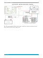
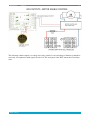
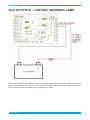
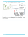
1
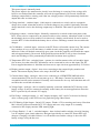
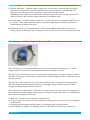
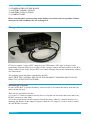
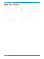
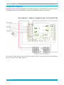
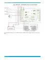
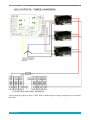
BCU-PEV-2.X
MANUAL
1.0
EV Power BCU-PEV-2.x Battery
Control Unit Instructions.
Introduction
The EV Power system consists of two main components, cell balancing/monitoring modules and the
Battery Control Unit (BCU). The cell modules bolt directly onto the LFP battery cells and work as
standalone balancers. They also monitor the cell voltage and raise an alarm via a daisy chain current
loop.
This manual deals with the BCU component only. There is a separate manual for the cell modules.
The EV Power Battery Control Unit is designed for Lithium Ion (eg. LiFePO4, LFP) batteries. It
has been developed to provide essential battery information in a simple concise format. It is
designed to be easy to install and use.
The BCU monitors overall battery parameters and also monitors the cell module signal current loop
for errors. If an error occurs the BCU takes action to rectify the problem and / or disables the
battery to prevent damage.
Via a remote OLED display the BCU can provide necessary user feedback of battery voltage,
current, power, amp-hours consumed and state-of-charge (SOC).
BCU-PEV Features
PAGE 1 OF 19
BCU-PEV-2.X
MANUAL
1.0
This PEV-2.x battery control unit is designed for applications that use Lithium batteries where
specific information about the battery’s voltage, current and state of charge is required. This may
include electric vehicles and solar power systems.
The unit is designed to to directly control the EV Power range of PFC chargers with the correct
charge curve. It has no internal contactor to directly disconnect the battery but it does have a 12V
relay output to drive an external (non-latching) relay.
The BCU works in conjunction with EV Power LFP Cell Modules to perform comprehensive
protection, monitoring and user feedback of key battery information.
Key Features:
•
•
•
•
•
•
•
•
•
•
•
•
•
•
•
•
•
Dash mount 2 line OLED display unit. Displays Volts, Amps, Amphours and % SOC
BCU is powered directly from the battery (12V, 24V, 36V, 48V, 60V, or 90-350VDC).
Voltage range must be specified at purchase.
External hall effect current sensor. No contact with HV cabling.
Enclosed flange mount polycarbonate box, IP54 rated against dust and splashing water.
Automatic battery capacity calibration
0-5V external fuel gauge output (fuel gauge not supplied)
External contactor driver, up to 2A coil current
Direct charge control for up to three PFC chargers. No CAN bus required.
Alternator (fast charge) enable output voltage free contact.
Current limit feature to prevent excessive discharge currents.
Complete Package includes BCU enclosure, external monitor display and current sensor
Self calibrating battery capacity calculations.
Internal alarm buzzer for audible warning.
Simple to understand and install.
Low power requirement
Reduced overall cost for instrumentation as no external Ah meters are required
Designed and manufactured in Australia
At order time the following information is required:
•
•
•
•
•
•
Number and type of cells in the battery (4-100 cells) 312V nominal maximum.
Amp-hour capacity of the battery pack (40-1000Ah)
Expected max current draw for current limiting (300A max continuous current)
Is charge interlock required to prevent discharge when charger is attached? (eg an EV)
Is the PFC charger external enable control?
External generator or fast charger start SOC% and stop SOC%
OR low SOC warning indicator level.
Read these instructions several times before commencing
installation.
PAGE 2 OF 19
BCU-PEV-2.X
MANUAL
1.0
BCU-PEV Specifications
SPECIFICATIONS
BCU-PEV-HV
MIN
MAX
Power Input (VDC), Note: 12VDC input option available for higher or lower voltages.
12
350
Power Consumption (W)
1
5
Cell Modules monitored
0
100
Weight (g) without accessories
550
Dimensions, 205 x 125 x 56mm
Volts resolution
±1
Amps resolution
±1
Ah resolution
±1
%SOC resolution
±1
Amps range, Note: current may be higher but will be measured as maximum 300A
-300
+300
Volts Range
0
350
Amphour Range
0
-1000
Battery temperature warning level (internal PTC thermistor)
70°C
State of Charge Range %
0
100
State of Charge output (Volts)
0
4.8
-
Objective of this manual
This manual will help with installation and operation of the battery control unit in conjunction with
EV Power cell balancing modules.
An understanding of electrical principles and competence with electrical tools is required. Ability
to use the volts, amps and Ohms setting of a multimeter is a prerequisite.
Disclaimer
This is a guide only. Potentially lethal voltages and currents are involved when working with
batteries. It is the responsibility of the installer to have the appropriate qualifications and
skills for working with high voltages. No liability whatsoever will be assumed by EV Power
for injury, accidents or damage resulting from the use of these instructions or any EV Power
supplied components.
PAGE 3 OF 19
BCU-PEV-2.X
MANUAL
1.0
Danger High Voltage
Do not try to charge or discharge Lithium (LFP) batteries
without the BCU installed. One over-charge or over-discharge
can cause permanent damage.
Charge the battery fully regularly and before storage.
Storage of a nearly flat battery can result in a dead battery.
Every effort has been made to make this apparatus as reliable and robust as possible. However
electronics can fail if incorrectly installed or used outside its design parameters. The BCU-PEV is
designed to be the last line of battery protection and should not always be relied upon to
disconnect the battery under normal operating conditions. Connected loads and chargers
should also have inbuilt low/high voltage cutoff mechanisms.
EV Power assumes no responsibility for battery damage resulting from failure of the BCU or
associated electronics.
How it works - Usage
The BCU performs a number of functions:
1) It monitors the cell balancing module loop for over/under voltage condition in any individual
cell, flags a weak, unbalanced or faulty cell.
2) Monitors the overall battery voltage for battery over or under-voltage condition (flat battery)
3) Checks for over-temperature conditions.
4) Monitors battery charge and discharge currents via an isolated hall effect current sensor.
Displays battery volts, amps, Amphours consumed and percent state-of-charge on a remote 2 line
OLED monitor.
5) Controls up to three PFC type chargers via switched or PWM enable lines (no CANbus
required)
6) Controls discharge devices/ motors via a switched enable line.
7) Voltage free contact (100mA max) to control an external generator or fast DC charger.
8) Provides direct 12V power to a discharge relay or DC contactor
PAGE 4 OF 19
BCU-PEV-2.X
MANUAL
1.0
9) Has an optional charger interlock input to prevent motor operation while a charger is connected.
10) Provides a 0-5V output to drive an external fuel level (SOC) meter.
Power Supply Choices
The BCU can be powered directly from the battery pack itself. This means that it does not
necessarily require an external 12V supply, although this is also an option.
There are four choices of internal power supply:
1) 9- 18VDC 12V Nominal (~4 cells)
2) 18 - 36VDC - 24V Nominal (~8 cells)
3) 36 - 72VDC - 48V Nominal (~16 cells)
4) 90 -350VDC - 96 - 312V Nominal (30 - 96 cells)
For reliable operation outside these voltage ranges choose the 12V supply and use a 12V auxiliary
battery for the BCU power supply.
For 12V powered BCU only the voltage sense cable should be connected to the battery positive and
negative via a 500mA fuse away from any traction cables.
Description of connections:
1) Power Supply Input as specified at order - This is the DC power to the BCU. The BCU-PEV has
an internal power supply to step down the battery pack voltage to isolated 12VDC which is used
for the controllers internal functions. It is designed for connection directly to the battery it is
controlling.
This has the advantage of safety, not mixing external 12V supply with battery HV lines. It also
means the BCU can be used without any other external peripherals or auxiliary batteries.
PAGE 5 OF 19
BCU-PEV-2.X
MANUAL
1.0
This power input is internally fused.
The power input is also monitored to check if over-discharge is occurring. If the voltage falls
below a user defined limit the controller will wait for approximately 30 seconds, disable the
discharge output, flash a warning, and if the low voltage persists it will permanently disable the
output and enter an alarm state.
2) Charge interlock - switched input - if this input is connected to a switch, such as a magnetic
charge door switch, when that switch is closed the charger(s) are enabled. Optionally when the
charge interlock is active the discharge output may be disabled. This must be specified at order
time.
3) Discharge control - switched input - Normally connected to a switch on the front panel of the
BCU. It may also be connected to an external switch or relay contacts, when that switch is closed
the discharge devices will be enabled. It is effectively a battery on/off switch. It can be used to
reset the BCU if it has disabled the battery due to an error. Discharge control does not affect the
charger.
4) Cell Modules - switched input - connects to the EV Power cell module current loop. The current
loop conducts if every cell in the battery is within its safe voltage range. It is open circuit
otherwise. If the cell module current loop goes open circuit the controller will disable the output
and wait approximately 30 seconds. If the problem persists the BCU will go into closedown
mode and discharge will be permanently disabled and an alarm state registered.
5) Temperature PTC fuse - switched input - operates in a similar manner to the cell modules input.
One or more low ohm value PTC thermistors can be connected in series to this input. The EV
Power supplied thermistor is 100 Ohm and increases to open circuit at approximately 70 Celcius.
6) Display monitor output - digital - four wires connecting to the remote display monitor and
button. The remote display shows volts, amps, Ah, kW and %SOC.
7) Current Sensor Input - analogue - three wires connecting to a LEM HTFS-200P hall effect
current transducer. This device can measure up to +/- 300 Amps. Currents beyond that are
acceptable but will not be measured. Generally such currents are for very short duration and will
not affect the overall Ah calculations.
8) Voltage Input - analogue - this is normally internally connected within the BCU directly to the
battery voltage. It may be connected externally to the battery for custom applications where the
BCU is powered by an external 12V supply.
9) Fuel Gauge - analogue output - 0 - 4.8V output, 0=empty, 4.8V = full. Can be used to directly
drive a remote gauge or the EV Power bar graph fuel gauge. Max 20mA.
10)12V Warning Light Output - On/off 12V output - Flashes 12V for warnings and errors. Note that
this is directly powered from the BCU 12V supply and not a relay output. It is normally
connected to the display monitor LED warning light.
11) Charge Enable 1, 2 and 3 - switched outputs - three isolated enable switches closed if charging
is to be enabled, open circuit otherwise. Designed specifically to control EV Power PFC type
chargers. Charging is disabled if there is a cell module error and the voltage is above the full
battery voltage set by the the user.
PAGE 6 OF 19
BCU-PEV-2.X
MANUAL
1.0
12) Enable Alternator - switched output, voltage free - can be used to start and stop an external
generator or to control the field of an alternator. It can also be used for controlling DC fast
charging. On = alternator active. Specified as upper and lower SOC limits.
Alternatively this output may be specified to switch on when the battery reaches a low SOC in
order to control a dash mount warning light and/or crawl home mode.
13) Enable Motor - switched output, voltage free - closed if the motor or discharge controller is to
be enabled. If the charge interlock input is closed this output may be disabled. It will also be
disabled during warnings and errors.
14) Discharge relay - 12V powered output - mirrors Enable Motor output with 12V power to
directly operate a discharge relay or contactor. It can control devices with coil currents up to 2A.
Mounting and Adjusting the Current Sensor
The current sensor is a non contact Hall effect type. It can accurately measure up to +/- 300A.
Larger currents are allowed but will be measured at the maximum level only.
The blue toroid must be placed over the main cable(s) to the positive or negative battery terminal.
Note that both charge and discharge currents must be routed through this cable or the unit will not
register correctly.
The top side of the toroid must face in the same direction as the conventional discharge current
flow. Check this by watching the display when discharging. Amps should be negative. When
charging the Amps display should be positive.
The current sensor comes factory calibrated to read zero amps at no-load. If non-zero amps shows
on the monitor or the Ah display on the monitor is drifting over time when there is no load then the
sensor may need adjusting. To do this:
1) Make sure all loads are disconnected except the BCU.
2) Using a small electricians screw driver adjust the trimpot on the sensor until “-0A” is displayed
on the monitor.
3) Gradually turn the trimpot until the minus sign disappears and no longer flashes.
4) Check that the Ah display is not drifting by leaving the BCU switched on for an hour or so.
PAGE 7 OF 19
BCU-PEV-2.X
MANUAL
1.0
The BCU Monitor Display Screen
The BCU has two display modes, just press and hold the monitor button to toggle between them.
This button may also be pressed to reset any error conditions.
MODE 1 : Battery Volts, Amps, Amphours consumed, State of Charge %
MODE 2 : Battery Volts, Kilowatts, E=============F fuel level display.
" DISCHARGE OFF " - an information only message when the discharge enable switch is off. The
main contactor driver is off but charging is still enabled.
" BATTERY FULL " - an information only message to register that the battery has passed 99%
charge. The Amphour counter is reset to zero at this point.
"BATTERY FAULT !!" - warning message. One or more of the battery cells is outside its safe
voltage range. This can occur if the battery pack is unbalanced or if there is a faulty cell or cell
module.
"BATTERY LOW!! " - warning message. The battery is under its empty voltage. This occurs when
the battery is flat or sometimes on high current draws during cold weather.
"BATTERY OVERVOLT" - warning message. Occurs if the battery is past its maximum allowable
voltage. This usually means the charger is incorrectly adjusted.
"OVER CURRENT! " - warning message. The battery is being drawn at more than its rated
current draw. If this condition persists for more than 30 seconds the BCU will close down.
"OVER TEMP !! " - warning message that the BCU thermistor is out of range, depends on its
location.
If a warning message is presented for more than 30 seconds the BCU will go into closedown
mode and disconnect the discharge relay and prevent charging. This may be temporarily reset
by pressing the display button or switching off/on the discharge enable line.
When the monitor registers an error the warning light will also flash. The number of flashes
indicates the highest priority error condition.
1 = CELL MODULE CURRENT LOOP - BROKEN LOOP BATTERY FAULT ERROR
PAGE 8 OF 19
BCU-PEV-2.X
MANUAL
1.0
2 = TEMPERATURE OUTSIDE RANGE
3 = BATTERY UNDER-VOLTAGE
4 = BATTERY OVER-VOLTAGE
5 = CURRENT LIMIT
Please note that there is a known bug in the display screen that causes it to produce Chinese
characters in cold conditions. We are working on it.
Charger Control
EV Power supplies a range of PFC chargers to suit LFP batteries. This type of charger can be
permanently connected directly to to battery. It has a charge control cable that connects to the BCU
charge control circuit. In this way the BCU can control charging directly and automatically without
user intervention.
The charging system should be controlled by the BCU.
NOTE THAT THE CONTROL INPUTS ON THE SEPARATE CHARGERS MUST NOT BE
DIRECTLY CONNECTED TOGETHER.
Discharge Control
In order for the BCU to protect the battery it must be able to disconnect the battery from the load
and/or disable the load.
There are two possibilities for this:
1) Use the 12V contactor output to directly drive a relay that can disconnect the motor and/or any
DC/DC converter or other loads.
2) Use the switched motor enable output to disable the motor, either by a disable function or by
inhibiting the throttle. If this output is employed then the 12V output of 1) can be used to control
only the DC/DC converter.
PAGE 9 OF 19
BCU-PEV-2.X
MANUAL
1.0
State of Charge Calculations
The BCU counts the Amps in and out of the battery and calculates the state of charge over time.
Charging amps in are measured as positive and amps discharge are measured as negative. Using this
information it also calculates the state of charge (SOC) of the battery as a percentage of the
battery Ah capacity. Note that there is no way to alter the default factory setting of the Ah capacity
of the battery pack to the BCU. However the BCU will self calibrate based on the deepest discharge
and battery voltage at deep discharge.
When the battery is discharged to a point where the low voltage warning is activated for more than
5 seconds the Ah capacity will be set to the current Ah level. This will become the limit of 0% SOC
capacity.
Should the battery lose capacity over time the SOC will be automatically updated to reflect this.
When the battery voltage rises above the fully charged limit the SOC is automatically reset to zero
as the battery is full.
Note that if power to the BCU is removed it will revert to the factory preset Ah capacity.
PAGE 10 OF 19
BCU-PEV-2.X
MANUAL
1.0
Connection Diagrams
Please refer to the connection diagrams on the following pages. The schematic is too large to put in
one diagram and several combinations of charge and discharge methods are possible.
For use with 12-60V batteries and also 90-312V batteries. BCU is powered directly from the battery
pack. No external 12V supply required.
PAGE 11 OF 19
BCU-PEV-2.X
MANUAL
1.0
For use with any battery of 12-312VDC. External 12VDC auxiliary supply required to power the
BCU.
PAGE 12 OF 19
BCU-PEV-2.X
MANUAL
For use with a single EV Power 700W or 1.5kW PFC charger.
PAGE 13 OF 19
1.0
BCU-PEV-2.X
MANUAL
1.0
3 phase charging with up to three 1.5kW, 3kW or 4kW chargers. Charger outputs may be connected
in parallel.
PAGE 14 OF 19
BCU-PEV-2.X
MANUAL
1.0
The BCU has a 12V powered output that can directly control a discharge contactor with a 12V coil
of up to 2A. In some situations a precharge circuit may be required to prevent the contacts from
“welding” shut if the application has large capacitors as many motor controllers do. This can be as
simple as a resistor which keeps the capacitors charged when the contactor is off. However take
care that it does not slowly drain the battery if left connected.
Note the use of the fuel gauge output to drive a 0-5V type gauge. Not suitable for direct
connection to automotive fuel gauges.
PAGE 15 OF 19
BCU-PEV-2.X
MANUAL
The 12V control output can also be used to control a small relay which can switch power to the
motor controller in the event of a battery fault.
PAGE 16 OF 19
1.0
BCU-PEV-2.X
MANUAL
1.0
The discharge enable output is a voltage free relay contact. It can switch up to 100mA so should be
used only in conjunction with signal circuits. It is NC and opens if the BCU enters the Closedown
state.
PAGE 17 OF 19
BCU-PEV-2.X
MANUAL
1.0
One of the options for this output is to switch a warning light in the event that the battery SOC falls
below a safe threshold, usually 10%. This is useful in traction applications. The output could also be
used to switch a motor controller input to “limp home” mode.
PAGE 18 OF 19
BCU-PEV-2.X
MANUAL
1.0
The alternative option for this voltage free output is to close when the battery SOC goes below a
lower threshold (say 30%) and then open when it reaches an upper threshold (say 80%). This can be
used in house power applications where a diesel generator with auto-start is employed to fast charge
the battery if it gets low.
Notes
PAGE 19 OF 19