1
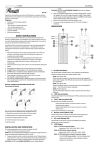
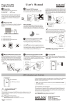
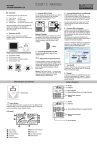
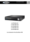
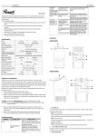
INSTALLATION AND OPERATION:
The following steps explain how to connect and operate the UPS.
1.
Connect the UPS to a grounded power outlet.
NOTE: It is recommended that the battery be charged for at least 8 hours to
ensure full charge before placing the UPS in service.
2.
Plug your computer, monitor or load to be protected into the “Battery Backup &
Surge Protection” outlets. (These outlets will provide emergency battery backup
Power Solutions for All Your Needs
power during power problems as well as protection from surges and spikes.)
The uninterruptible power system (UPS) protects your sensitive electronic equipment
CAUTION: Do NOT plug LASER PRINTERS into the “Battery Backup”
outlets.
CAUTION: Do NOT plug ACCESSORY SURGE strips into the “Battery
Backup outlets.
3. Plug your peripheral equipment or non-critical loads (printer, scanner, fax,
speaker, etc.) into the “Surge Protection” outlets. (These outlets provide
surge and spike protection only they will NOT provide battery backup
power during a utility power failure).
from power problems such as power failures, power sags, power surges, brownouts,
4.
Switch on the UPS while the connected equipment is off.
and line noise.
5.
Turn on your connected equipment when the “AC mode” LED light is illuminated.
Features:
INDICATORS
TOW-1500LCD
USER’S MANUAL
•
•
Processor-controlled voltage regulation
Eight outlets
- Four with surge and backup protection
- Four with surge protection only
•
Telephone line surge protection jacks
•
Cold start capability
•
USB communication port
SAFETY INSTRUCTIONS
Once you have received the UPS product, you should remove and inspect the
product for shipping damage. If any damage is found, please notify the carrier and
your dealer. Please keep the shipping carton and the packing foam in the event the
product must be returned to the factory for service.
A qualified technician must perform maintenance, other than battery replacement.
Failure to do so could result in an electrical shock.
Although the unit may be
unplugged from utility power, hazardous voltage still may be present through the
battery.
1.
Place the UPS indoors in an area that has adequate airflow and is free from
excessive dust. Do NOT allow the UPS to be exposed to moisture, rain,
excessive heat or direct sunlight.
2.
1. On/Off Push Button
This On/Off switch controls power to your equipment and performs a self-test
to detect inverter, line, battery status & LEDs.
NOTE: Turn on the UPS.
Press and hold the switch for more than one second and release the
switch after the beep. The UPS will start and provide the stable power to
your equipments.
Use of the UPS product in life support applications where failure of this
equipment can reasonably be expected to cause failure of life support equipment
or to significantly affect its safety or effectiveness is NOT recommended.
3.
Always disconnect the input power cord from the wall outlet before replacing the
NOTE: Turn off the UPS.
Press and hold the switch for more than one second and release the
switch. The UPS will shut down completely.
battery.
4.
When replacing the battery, use the same number and type of battery.
5. Do NOT dispose of the battery in a fire: the battery may explode.
6. Do NOT open or mutilate the battery. Batteries contain an electrolyte that
is toxic and harmful to both the skin and eyes.
7.
8.
NOTE: Perform Self-test.
The UPS will perform self-test for about 5 seconds when the UPS is
turned on.
Proper disposal of the battery is required. Please refer to your local
laws/regulations regarding battery disposal.
Use tools with insulated handles to replace the battery to avoid personal injury.
Due to energy hazards, please remove wristwatches and jewelry such as rings
when replacing battery.
BATTERY CONNECTION REQUIRED BEFORE USE!
Connecting the Battery!
2. LCD Choose Button
Click the switch each time it will display the UPS's special status and data’s
on the screen.
3.
Fault / Warning (Red) LED
Indicates that a fault condition has occurred.
-
Flashing Red LED indicates an overload condition or that the
battery should be replaced.
-
Solid On LED indicates that the output is shorted or an internal
UPS fault exits.
See the Indicator Table below for further detail.
4. Backup mode (Yellow) LED
Indicates that the UPS is operating on battery and providing regulated AC
power to the backup only outlets and the connected equipment.
5.
AC mode (Green) LED
Indicates that AC utility power is present and regulated power (AVR) is
applied to the connected equipment.
6.
LCD Display
State 1: UPS load capacity display.
How to hook up the battery before installing the UPS?
1. Remove the screws from the bottom of the front panel.
2. Grasp the panel cover downward off the UPS.
3. Connect the battery positive wire (red).
4. Put the front panel cover upward.
5. Bolt the screws.
Load pixel is 20%--40%--60%--80%--100%
State 2: UPS battery capacity display.
Battery pixel is 20%--40%--60%--80%--100%
State 3: UPS input/output voltage & frequency display.
Click the LCD choose switch, it will cycle display input
voltage, input frequency, output voltage and output
frequency on the screen.
7. USB Communication Port
Battery Name
Recycling inside the USA
The built-in USB port connects to your computer. The PowerGuard Smart
Vision Battery
1-877-730-2877
First Power Battery
1-877-730-2877
BB Battery
1-800-278-8599
monitoring and shutdown software provided can automatically save your files
and shut down your computer in the event of a prolonged power outage. The
software also provides information regarding the status of your utility power line
Installing software
SPECIFICATIONS
Follow the on-screen
instructions.
Model Numbers
TOW-1500LCD
Capacity
1500 VA / 900W
120 Vac
Nominal Input Voltage
If autoplay is not enabled on the computer, please follow instructions below:
‧ Double-click on My Computer on the desktop.
‧ Double-click on the CD-ROM drive icon and follow the on-screen
instructions.
Nominal Output Voltage
Automatic Voltage
Regulation (AVR)
Frequency
108-130Vac(±3%)
50 / 60 Hz auto sensing
8 Outlets (4 Battery Backup & Surge Protection;
4 Surge Protection only)
Outlets
8. Data /Phone/Fax Protection Connectors
120 Vac
Lighting / Surge Protection
320 Joules
9. “Surge Only” Outlets
Transfer time to Battery/AC
2-6ms typical
Four Nema 5-15R output receptacles that will provide surge and spike
Battery Type
protection only
Maintenance free lead-acid battery
Battery Specification
(2)* 12V 9 Ah
10. “Battery & Surge” Outlets
Typical Backup Time
Up to 55 Minutes
Four Nema 5-15R output receptacles that will provide both battery backup and
LAN / Phone / Fax Protection
surge protection.
Short Circuit Protection
11. AC Input Power Cord
Plug the AC power cord into your power source
Circuit Breaker
Communication Port
USB
Operation Temperature
0°C–40°C
Operation Relative Humidity
12. Coax in :
RJ11/45
0 to 95% non-condensing
Storage Temperature
TV/TNT/Satellite reception protection
-15°C–50°C
Net Weight
13. Circuit Breaker (re-settable)
29.3 lb
10.8 x 3.4 x 16.1 IN
Dimensions (HxWxD)
The button will protrude when the overload condition occurs. If the button
protrudes, disconnect some non-essential equipment and reset the circuit
Specifications may change without prior notice.
breaker by pushing the button inward.
All Trade Marks Belong To Their Respected Owners
14. Coax out:
TROUBLESHOOTING
TV/TNT/Satellite reception protection
Symptom
INDICATOR TABLE
Status Indicators
The UPS provides both visual and audible status indicators. Visual indicators consist
of three LEDs to represent the following conditions:
•
On utility power operation
•
On battery power operation
•
UPS fault/alarm
LED and Alarm Indicator Table
UPS Status
Self-test
AC mode
Normal
( on utility)
Self Low
battery
overload
DC mode
( on battery)
Normal
Low
battery
Overload
Short/Fault mode
Over-Bat/Bat Fault
Green
LED
Red LED
Yellow
LED
Alarm
On
Blink 1
X
X
B1
X
On
Blink2
X
B5
On
Blink2
X
B2
X
X
X
X
On
Blink2
B1
B3
X
X
X
Blink2
On
Blink2
On
X
X
B2
On
B4
* Blink 1 : ON 0.5 seconds / OFF 1 seconds
* Blink 2 : ON 0.25 seconds / OFF 0.25 seconds
* B1: 1 beep / 5 seconds: ON 0.25 seconds / OFF 4.75 seconds
* B2: 1 beep / 0.5 seconds :ON 0.25 seconds / OFF 0.25 seconds
* B3 : 2 beeps / 5 seconds: ON 0.25 seconds / OFF 0.25 seconds 2 times, 4 seconds OFF
* B4 :
3 beeps / 5 seconds: ON 0.25 seconds / OFF 0.25 seconds 3 times, 3.5 seconds OFF
* B5: 3beeps / 30seconds :ON 0.25 seconds / OFF 0.25 seconds 3 times, 28.5seconds OFF
Recycling Information:
Your UPS contains Non-Spill Sealed Lead Batteries. On the battery you will
find the battery name. Please reference the chart below for recycling
information. Other brand(s) of battery please contact Maruson Technology
Corp. If outside the USA or Canada, please contact your local authorized
distributor.
Possible Cause
UPS will not turn The UPS is not
on
connected to the
power source.
Circuit Breaker has
tripped.
Action to Take
Ensure the UPS is securely
connected to an AC outlet.
Reduce the amount of equipment
plugged into the “Battery Backup &
Surge Protection” outlets of the UPS.
Reset the circuit breaker by pushing it
back in. Switch the UPS back on.
UPS is making a The “Battery Backup & Turn off the UPS and reduce the
amount of equipment connected to
continuous sound Surge Protection”
these outlets.
outlets are overload.
and the
“Overload”
indicator is on
UPS does not The UPS battery is
Charge the battery for 8 hours. The
discharged due to a
UPS runtime is reduced until the
provide
power outage and has
battery is fully charged.
expected
not recharged.
runtime
Back-UPS is heavily Unplug non-essential equipment
loaded.
(printers, scanners, etc) from the
Battery Backup outlets and plug into
'Surge Only' outlets
Disconnect non-essential equipment
UPS does not
The UPS circuit
power essential breaker “ tripped” . from the UPS. Reset (push in) the
circuit breaker and switch the UPS on.
equipment during
Plug equipment in one-at-a-time. If the
an outage
circuit breaker trips again, disconnect
the device that caused the breaker to
trip.
Replace the battery or the battery
The battery has
reached the end of its module.
life.
Unplug device from 'Surge Only' outlet
Equipment plugged
and move to a 'Battery Backup outlet.
into a Surge Only
outlet.
Flashing
Internal UPS fault.
Contact Technical Support (see
Indicators
Service and Support below).
Maruson Technology Corp. Tel: (626)912-8388 Fax: (626)912-8680
18557 East Gale Ave.
E-mail: [email protected]
City of Industry, CA. 91748 Web: www.MarusonUSA.com