1
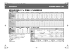
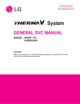
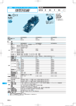
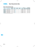
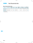
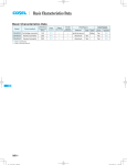
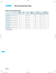
Basic Characteristics Data
Basic Characteristics Data
Model
TUNS50F
TUNS100F
TUNS300F
TUNS500F
TUNS700F
Circuit method
Switching
frequency
[kHz]
Active filter
80-600
Flyback converter
100-300
Active filter
80-600
Forward converter
300
Active filter
100
Half-bridge converter
400
Active filter
100
Half-bridge converter
400
Active filter
100
Half-bridge converter
400
*1 The value of input current is at ACIN 100V and rated load.
*2 Refer to instruction manual.
TUNS
TUNS-12
Input
current
[A] *1
Inrush
current
protection
circuit
Material
0.67
Thermistor
Aluminum
1.3
Thermistor
3.6
PCB/Pattern
Single Double
sided
sided
Series/Parallel
operation availability
Series
operation
Parallel
operation
Yes
Yes
*2
Aluminum
Yes
Yes
*2
SCR
Aluminum
Yes
Yes
*2
6.0
SCR
Aluminum
Yes
Yes
*2
8.6
SCR
Aluminum
Yes
Yes
*2
AC-DC Power Supplies Power Module type Instruction Manual
TUNS50F, TUNS100F
TUNS300F, TUNS500F, TUNS700F
1 Pin Connection
TUNS-14
1 Pin Connection
TUNS-21
2 Connection for Standard Use
TUNS-14
2 Connection for Standard Use
TUNS-21
3 Wiring Input/Output Pin
TUNS-15
3 Wiring Input/Output Pin
TUNS-22
3.1
Wiring input pin
TUNS-15
3.1
Wiring input pin
TUNS-22
3.2
Wiring output pin
TUNS-15
3.2
Wiring output pin
TUNS-22
3.3
Wiring +BC/-BC pins
TUNS-15
3.3
Wiring +BC/-BC pins
TUNS-22
4 Function
4 Function
TUNS-23
4.1
Input voltage range
TUNS-16
4.1
Input voltage range
TUNS-23
4.2
Overcurrent protection
TUNS-16
4.2
Overcurrent protection
TUNS-23
4.3
Overvoltage protection
TUNS-16
4.3
Peak current protection
TUNS-23
4.4
Thermal protection
TUNS-16
4.4
Overvoltage protection
TUNS-23
4.5
Remote sensing
TUNS-16
4.5
Thermal protection
TUNS-23
4.6
Adjustable voltage range
TUNS-17
4.6
Remote ON/OFF
TUNS-23
4.7
Withstanding Voltage/Isolation Voltage
TUNS-17
4.7
Remote sensing
TUNS-24
4.8
Adjustable voltage range
TUNS-24
4.9
Inverter operation monitor (IOG)
TUNS-25
4.10
Withstanding Voltage/Isolation Voltage
TUNS-25
5 Series and Parallel Operation
TUNS-17
5.1
Series operation
TUNS-17
5.2
Parallel operation
TUNS-17
6 Implementation-Mounting Method
7
TUNS-16
5 Series and Parallel Operation
TUNS-25
5.1
Series operation
TUNS-25
5.2
Parallel operation
TUNS-25
5.3
N+1 redundant operation
TUNS-26
6 Implementation-Mounting Method
TUNS-26
TUNS-18
6.1
Mounting method
TUNS-18
6.2
Stress to the pins
TUNS-18
6.3
Cleaning
TUNS-18
6.4
Soldering temperature
TUNS-18
6.5
Derating
TUNS-18
6.1
Mounting method
TUNS-26
6.6
Heat sink (Optional parts)
TUNS-19
6.2
Stress to the pins
TUNS-26
6.3
Cleaning
TUNS-26
6.4
Soldering temperature
TUNS-26
6.5
Derating
TUNS-26
Lifetime expectancy depends on TUNS-20
stress by temperature difference
7 Peak current
8
TUNS-27
Lifetime expectancy depends on TUNS-28
stress by temperature difference
TUNS-13
TUNS
AC-DC Power Supplies Power Module type
1 Pin Connection
¿TUNS50F
TUNS50F, TUNS100F
Instruction Manual
2 Connection for Standard Use
¡To use TUNS series, connection shown in Fig.2.1 and external
components are required.
7-VOUT
6TRM
5+VOUT
1AC1
¡This product uses conduction cooling method (e.g. heat radiation
from the aluminum base plate to the attached heat sink).
Reference: 6.5 ”Derating”
2AC2
3+BC 4-BC
2-FG
Heatsink
¿TUNS100F
+S
TH1
F1
9-VOUT
1AC1
8-S
7TRM
6+S
2AC2
AC IN
Noise
filter
FG
FG
+VOUT
TUNS50F
Co
TUNS100F
AC2
-VOUT
AC1
C1
FG
+BC
Cbc
+
Load
-BC -S
+ C2
CY
5+VOUT
+S, -S : TUNS100F
3+BC 4-BC
4-FG
Fig.2.1 Connection for standard use
Fig.1.1 Pin connection (bottom view)
Table 1.1 Pin connection and function
TUNS
No.
Pin
Function
TUNS50F TUNS100F Connection
AC1
1
1
AC input
AC2
2
2
+BC
+BC output
3
3
-BC
-BC output
4
4
+VOUT +DC output
5
5
-VOUT -DC output
7
9
-S
Remote sensing (-)
8
+S
Remote sensing (+)
6
TRM
Adjustment of output voltage
6
7
FG
Mounting hole (FG)
TUNS-14
Table 2.1 External components
No. Symbol
Components
1
F1 Input fuse
2
C1 Input Capacitor
3
Noise Filter
4
CY Y capacitor
5 TH1 Inrush current protection thermistor
6
Co Output capacitor
7 Cbc Smoothing Capacitor for boost voltage
8
C2 Capacitor for boost voltage
9
Heatsink
Reference
3.1 “Wiring input pin (1)”
3.1 “Wiring input pin (2)”
3.1 “Wiring input pin (3)”
3.1 “Wiring input pin (4)”
3.2 “Wiring output pin (1)”
3.3 “Wiring +BC/-BC pins (1)”
3.3 “Wiring +BC/-BC pins (2)”
6.6 “Heat sink”
AC-DC Power Supplies Power Module type
3 Wiring Input/Output Pin
Instruction Manual
TUNS50F, TUNS100F
¡The output voltage may become unstable at low temperature due
to the ESR of power thermistor. In this case, increase the capacitance of Cbc more than recommended value or connect same
capacitors in parallel. Please evaluate before use.
3.1 Wiring input pin
3.2 Wiring output pin
(1) F1 : External fuse
¡Fuse is not built-in on input side. In order to protect the unit, install
the slow-blow type fuse on input side (as shown in Table 3.1).
Table 3.1 Recommended fuse (Slow-blow type)
Model
Rated current
TUNS50F
2A
TUNS100F
3.15A
(1) Co : Output capacitor
¡Install an external capacitor Co between +VOUT and -VOUT pins
for stable operation of the power supply (Fig.2.1).
Recommended capacitance of Co is shown in Table 3.3.
¡Select the high frequency type capacitor. Output ripple and startup waveform may be influenced by ESR-ESL of the capacitor and
the wiring impedance.
(2) C1 : External Capacitor for input side
¡Install a capacitor Co near the output pins (within 50mm from the
pins).
¡Install a film capacitor as input capacitor C1 of which the capacitance and ripple current capability are above the values shown in
¡When the power supply is used under 0C ambient temperature,
output ripple voltage increases. In this case, connect 3 capacitors
Table 3.2.
Co in parallel connection.
¡Use a safety approved capacitor with 250V ac rated voltage.
¡If C1 is not connected, it may cause the failure of the power sup-
Table 3.3 Recommended capacitance Co[μF]
ply or external components.
Temperature of base plate
Tc=0 to +100C
Tc=-40 to +100C
Model
Table 3.2 Input Capacitor C1
No.
Model
1
2
TUNS50F
TUNS100F
Rated ripple
Voltage Capacitance
current
1μF or more 3A or more
AC250V
1μF or more 3A or more
Output voltage
(V)
5
12
24
TUNS50F
TUNS100F
TUNS50F
TUNS100F
2200
470
220
2200
470
220
2200×3
470×3
220×3
2200×3
470×3
220×3
The specified ripple and ripple noise are measured by the method
(3) CY : Noise filter/Decoupling capacitor
introduced in Fig.3.1.
50mm
¡The product doesn’t have noise filter internally.
Please connect external noise filter and primary decoupling capaci-
+S
¡The operation of the power supply may be unstable due to the
resonance of the filter or inductance.
¡Install a correspondence filter, if it is required to meet a noise
standard or if the surge voltage may be applied to the unit.
¡Install a primary decoupling capacitor CY, with more than 470pF,
near the input pins (within 50mm from the pins).
¡When the total capacitance of the primary decoupling capacitor is
more than 8800pF, the nominal value in the specification may not
TH1
F1
tor CY for low line noise and stable operation of the power supply.
AC IN
Noise
filter
FG
FG
C4 :
5V,12V 10mF
24V 4 .7mF
+VOUT
TUNS50F
TUNS100F
AC2
-VOUT
AC1
C1
FG
+BC
Cbc
Co
TUNS
+
C4 Load
-BC -S
+ C2
1.5m
CY 50W
Coaxial
Cable
R
Oscilloscope
BW:100MHz
C R=50W
C=0.01mF
+S, -S : TUNS100F
Fig.3.1 Method of Measuring Output Ripple and Ripple Noise
be met by the Hi-Pot test between input and output. A capacitor
should be installed between output and FG.
3.3 Wiring +BC/-BC pins
(4) TH1 : Inrush current limiting thermistor
(1) Cbc : Smoothing capacitor for boost voltage
¡It has a possibility that internal components fail by inrush current,
so please use power thermistor or inrush current limiting circuit to
¡In order to smooth boost voltage, connect Cbc between +BC and
-BC. Recommended capacitance of Cbc is shown in Table3.4.
keep input current below 60A.
¡If you use power thermistor and turn the power ON/OFF repeatedly within a short period of time, please have enough intervals
so that a power supply cools down before being turned on. And
appropriate intervals should be set even if inrush current limiting
circuit except power thermistor is used.
¡Note that +BC and -BC terminals have high voltage (DC385V typ).
¡Keep the capacitance within the allowable external capacitance.
¡Select a capacitor of which the boost voltage ripple voltage does
not exceed 30Vp-p.
¡When the power supply is operated under -20C, it may make
the boost voltage unstable due to the characteristic of equivalent
series resistor. Please choose the capacitor which has more than
recommended capacitance.
TUNS-15
AC-DC Power Supplies Power Module type
Table 3.4 Recommended capacitance Cbc
No.
Model
Voltage
Cbc
1
TUNS50F
DC420V
82μF
Allowable
capacitance range
47 to 150μF
2
TUNS100F
or more
120μF
68 to 220μF
TUNS50F, TUNS100F
Instruction Manual
4.4 Thermal protection
¡When the power supply temperature is kept above 100C, the
thermal protection will be activated and simultaneously shut down
the output.
When the thermal protection is activated, shut off the input voltage
and eliminate all the overheating conditions. To recover the output
(2) C2 : Capacitor for boost voltage
voltage, keep enough time to cool down the power supply before
¡Install external capacitors C2 with capacitance shown in table 3.5.
¡If capacitors C2 are not installed, it may cause the failure of the
power supply or external components.
Table 3.5 Recommended capacitance C2
No.
Model
Voltage
1
2
TUNS50F
TUNS100F
DC450V
Rated ripple
current
0.47μF or more 1A or more
0.47μF or more 1A or more
Capacitance
turning on the input voltage again.
4.5 Remote sensing
¿TUNS50F
¡Remote sensing is not built-in.
¿TUNS100F
¡Remote sensing is built-in.
(1) When the remote sensing function is not in use
4 Function
+S
TUNS100F
4.1 Input voltage range
¡The input voltage range is from 85 VAC to 264 VAC.
¡In cases that conform with safety standard, input voltage range is
AC100-AC240V(50/60Hz).
¡Be aware that use of voltages other than those listed above may
result in the unit not operating according to specifications, or may
cause damage. Avoid square waveform input voltage, commonly
used in UPS units and inverters.
TUNS
4.2 Overcurrent protection
¡Overcurrent protection is built-in and comes into effect at over
105% of the rated current.
Overcurrent protection prevents the unit from short circuit and
+VOUT
+
Load
Co
-VOUT
-S
Short at pin root
Fig. 4.1 Connection when the remote sensing is not in use
¡When the remote sensing function is not in use, it is necessary to
confirm that pins are shorted between +S & +VOUT and between
-S & -VOUT.
¡Wire between +S & +VOUT and between -S & -VOUT as short as
possible.
Loop wiring should be avoided.
This power supply might become unstable by the noise coming
from poor wiring.
(2) When the remote sensing function is in use
overcurrent condition. The unit automatically recovers when the
Wire as close as possible
fault condition is cleared.
¡When the output voltage drops at overcurrent, the average output
current is reduced by intermittent operation of power supply.
4.3 Overvoltage protection
¡Overvoltage protection circuit is built-in. If the overvoltage protection circuit is activated, shut down the input voltage, wait more
+S
TUNS100F +VOUT
-VOUT
-S
+
Co
Load
Fig. 4.2 Connection when the remote sensing is in use
than 3 minutes and turn on the AC input again to recover the output voltage. Recovery time varies depending on such factors as
input voltage value at the time of the operation.
Remarks:
Please note that devices inside the power supply might fail when
voltage of more than rated output voltage is applied to output terminal of the power supply. This could happen when the customer
tests the overvoltage performance of the unit.
To check the function of overvoltage protection, adjust the output
voltage by changing TRM voltage. Please contact us for details.
TUNS-16
¡Twisted-pair wire or shield wire should be used for sensing wire.
¡Thick wire should be used for wiring between the power supply
and a load.
Line drop should be less than 0.5V.
Voltage between +VOUT and -VOUT should remain within the
output voltage adjustment range.
¡If the sensing patterns are short, heavy-current is drawn and the
pattern may be damaged.
The pattern disconnection can be prevented by installing the protection parts as close as a load.
AC-DC Power Supplies Power Module type
¡As wiring or load impedance may generate oscillation or large
fluctuations in output voltage, make sure enough evaluation is
given advance.
4.6 Adjustable voltage range
¡Output voltage between +VOUT and -VOUT can be adjusted by
connecting external resistors to TRM.
¡When the output voltage adjustment is not used, open the TRM
pin respectively.
¡When the output voltage adjustment is used, note that the overvoltage protection circuit operates when output voltage is set too
high.
TUNS50F, TUNS100F
Instruction Manual
5 Series and Parallel
Operation
5.1 Series operation
¡Series operation is available by connecting the outputs of two or
more power supplies as shown below. Output current in series
connection should be lower than the lowest rated current in each
unit.
Power
Supply
depending on the types of resistors and potentiometers, please
Power
Supply
use resistors and potentiometers of the following specifications:
Resistors ............. Metal film type, coefficient less than ±100ppm/C
Power
Supply
Output voltage will increase if the resistance between 2 and 3 is
reduced by turning the potentiometer.
Power
Supply
Recommended values for external components are shown in
Load
(b)
¡Output voltage can be adjusted by connecting an external potentiometer (VR1) and resistors (R1 and R2) as shown in Fig. 4.3.
Load
Potentiometers ... Cermet type, coefficient less than ±300ppm/C
Load
(a)
¡The wiring to the potentiometer should be as short as possible.
As the ambient temperature fluctuation characteristics deteriorate
Table 4.1.
Consult us if the power module is used in a different configuration.
5.2 Parallel operation
+VOUT
+S
External Resistor R1
2
1
External VR1
5kW
3
External Resistor R2
¡Parallel operation is not possible.
¡Redundancy operation is available by wiring as shown below.
+S
+VOUT
I1
I3
-VOUT
-S
-S
-VOUT
+S, -S : TUNS100F
Fig. 4.3 Connecting External Devices (TUNS50F/TUNS100F)
+S
+VOUT
Table 4.1 Recommended Values of External Resistors (TUNS50F, TUNS100F)
-VOUT
-S
No.
1
2
3
Output
Voltage
5V
12V
24V
Adjustable Range
VOUT±5%
VOUT±10%
R1
R2
R1
R2
10kW
2.7kW
4.7kW
1kW
12kW
2.2kW
5.6kW
560W
27kW
1.8kW
15kW
470W
4.7 Withstanding Voltage / Isolation Voltage
TUNS
Load
TUNS50F TRM
TUNS100F
Fig. 5.1 Examples of series operation
I2
+S, -S : TUNS100F
Fig. 5.2 Example of Redundancy Operation
¡Even a slight difference in output voltage can affect the balance
between the values of I1 and I2.
Please make sure that the value of I3 does not exceed the rated
current of a power supply.
¡When testing the withstanding voltage, make sure the voltage
is increased gradually. When turning off, reduce the voltage
I3
the rated current value
gradually by using the dial of the hi-pot tester. Do not use a
voltage tester with a timer as it may generate voltage several
times as large as the applied voltage.
TUNS-17
AC-DC Power Supplies Power Module type
6 ImplementationMounting Method
TUNS50F, TUNS100F
Instruction Manual
6.3 Cleaning
¡Clean the product with a brush. Prevent liquid from getting into
the product.
Do not soak the product into liquid.
¡Do not stick solvent to a name plate or a resin case.
(If solvent sticks to a name plate or a resin case, it will cause
6.1 Mounting method
to change the color of the case or to fade letters on name plate
¡The unit can be mounted in any direction. When two or more
power supplies are used side by side, position them with proper
away.)
¡After cleaning, dry them enough.
intervals to allow enough air ventilation. Aluminum base plate temperature of each power supply should not exceed the temperature
range shown in derating curve.
¡Avoid placing the AC input line pattern layout underneath the unit.
It will increase the line conducted noise. Make sure to leave an
ample distance between the line pattern layout and the unit. Also
6.4 Soldering temperature
¡Flow soldering: 260C for up to 15 seconds.
¡Soldering iron (26W): 450C for up to 5 seconds.
avoid placing the DC output line pattern underneath the unit be-
6.5 Derating
cause it may increase the output noise. Lay out the pattern away
(1) Input voltage derating curve
from the unit.
¡Avoid placing the signal line pattern layout underneath the unit
because the power supply might become unstable. Lay out the
Input voltage derating curve is shown in Fig.6.2.
pattern away from the unit.
Load Factor [%]
¡High-frequency noise radiates directly from the unit to the atmosphere. Therefore, design the shield pattern on the printed circuit
board and connect it to FG.
The shield pattern prevents noise radiation.
¡When a heat sink cannot be fixed on the base plate side, order the
power module with ”-T” option. A heat sink can be mounted by affix-
100
80
85 90
ing a M3 tap on the heat sink.
[AC V]
Fig. 6.2 Input voltage derating curve
Please make sure a mounting hole will be connected to a grounding
capacitor CY.
(2) Output voltage derating curve
Table 6.1 Mounting Hole Configuration
TUNS
Standard
Optional : -T
¡Use the power modules with conduction cooling (e.g. heat dissipation from the aluminum base plate to the attached heat sink).
Mounting hole
M3 tapped
f3.4 thru
Fig. 6.3 shows the derating curves with respect to the aluminum
base plate temperature. Note that operation within the hatched
areas will cause a significant level of ripple and ripple noise.
6.2 Stress to the pins
¡When too much stress is applied to the pins may damage internal
connections. Avoid applying stress in excess of that shown in Fig.
6.1.
¡Please measure the temperature on the aluminum base plate
edge side when you cannot measure the temperature of the center part of the aluminum base plate.
In this case, please take 5deg temperature margin from the derat-
¡The pins are soldered onto the internal PCB.
Therefore, Do not bend or pull the leads with excessive force.
ing characteristics shown in Fig.6.3.
¡Mounting hole diameter of PCB should be 3.5mm to reduce the
stress to the pins.
sible when the up and down of the temperature are frequently
¡Fix the unit on PCB (fixing fittings) by screws to reduce the stress
to the pins. Be sure to mount the unit first, then solder the unit.
Contact us for more information on cooling methods.
+VOUT, -VOUT
Less than
39.2N(4kgf)
Less than
39.2N(4kgf)
Less than
39.2N(4kgf)
Others
Less than
19.6N(2kgf)
Less than
19.6N(2kgf)
Fig. 6.1 Stress to the pins
TUNS-18
Less than
19.6N(2kgf)
Please reduce the temperature fluctuation range as much as posgenerated.
AC-DC Power Supplies Power Module type
10
100
1
(75)
50
1TUNS50F/TUNS100F
0
-40
-20
0
20
40
60
(85)
80
100
Aluminum base plate temperature Tc [C]
Thermal resistance(C/w)
Load Factor [%]
Instruction Manual
TUNS50F, TUNS100F
8
F-QB -F1/F2
F-QB -F3/F4
F-QB -F5/F6
6
4
2
Tc
Measuring point
0
0.0
0.5
1.0
1.5
2.0
Wind velocity(m/s)
2.5
3.0
Fig.6.5 Thermal Resistance of Heat Sink(Forced Air)
¿TUNS100F
TUNS50F
TUNS100F
Table 6.2 Types of Heat Sinks Available
Size[mm]
No.
Fig.6.3 Derating curve
6.6 Heat sink (Optional parts)
¡The power module works with conduction cooling and needs heat
dissipation using heat sinks. Optional heat sinks are available for
TUNS50F/TUNS100F Series. Refer to Table 6.1 and Table 6.2 for
1
2
3
4
5
6
Model
H
F-CBS-F1 12.7
F-CBS-F2 12.7
F-CBS-F3 25.4
F-CBS-F4 25.4
F-CBS-F5 38.1
F-CBS-F6 38.1
W
details on the thermal resistance of heat sinks.
W
D
57.9
58.4
57.9
58.4
57.9
58.4
61.5
61.0
61.5
61.0
61.5
61.0
Thermal resistance[C/W]
Convection
Forced Air
(0.1m/s)
7.5
4.6
3.0
Style
Horizontal
Vertical
Horizontal
Refer Fig.6.7
Vertical
Horizontal
Vertical
W
¿TUNS50F
1
2
3
4
5
6
F-QB-F1
F-QB-F2
F-QB-F3
F-QB-F4
F-QB-F5
F-QB-F6
H
W
D
12.7
12.7
25.4
25.4
38.1
38.1
58.4
58.7
58.4
58.7
58.4
58.7
37.6
37.3
37.6
37.3
37.6
37.3
14.0
7.5
5.0
D
Thermal resistance[C/W]
Convection
Forced Air
(0.1m/s)
Style
Horizontal
Vertical
Horizontal
Refer Fig.6.5
Vertical
Horizontal
Vertical
TUNS
H
Model
W
H
Size[mm]
No.
D
Table 6.1 Types of Heat Sinks Available
W
Horizontal
Vertical
D
D
Fig. 6.6 Heat Sink Types
Vertical
Fig.6.4 Heat Sink Types
Thermal resistance(C/w)
Horizontal
H
H
6
5
F-CBS-F1/F2
F-CBS -F3/F4
F-CBS-F5/F6
4
3
2
1
0
0.0
0.5
1.0
1.5
2.0
Wind velocity(m/s)
2.5
3.0
Fig.6.7 Thermal Resistance of Heat Sink(Forced Air)
TUNS-19
AC-DC Power Supplies Power Module type
7 Lifetime expectancy depends on
stress by temperature difference
¡Regarding lifetime expectancy design of solder joint, following
contents must be considered.
It must be careful that the soldering joint is stressed by temperature rise and down which is occurred by self-heating and ambient
temperature change.
The stress is accelerated by thermal-cycling, therefore the temperature difference should be minimized as much as possible if
temperature rise and down is occurred frequently.
¡Product lifetime expectancy depends on the aluminum base plate
central temperature difference (DTc) and number of cycling in a
day is shown in Fig.7.1.
If the aluminum base plate center part temperature changes frequently by changing output load factor etc., the above the lifetime
expectancy design should be applied as well.
Lifetime expectancy [years]
Please contact us for details.
10
5
1time
2times
3times
4times
5times
0
25
TUNS
ON/OFF /1day
ON/OFF /1day
ON/OFF /1day
ON/OFF /1day
ON/OFF /1day
30
35
40
45
50
55
60
65
70
The aluminum base plate central temperature differenceDTc [C]
Fig.7.1 Lifetime expectancy against rise/fall temperature difference
Application manuals available at our website.
Recommended external components are also introduced for your
reference.
TUNS-20
TUNS50F, TUNS100F
Instruction Manual
AC-DC Power Supplies Power Module type TUNS300F, TUNS500F, TUNS700F
1 Pin Connection
2 Connection for Standard Use
¿TUNS300F/TUNS500F/TUNS700F
1 AC1
7 -VOUT
2 AC2
6 +VOUT
8 -S
9 +S
0 TRM
å IOG
¡To use TUNS series, connection shown in Fig.2.1 and external
components are required.
¡This product uses conduction cooling method (e.g. heat radiation
from the aluminum base plate to the attached heat sink).
Reference: 6.5 ”Derating”
Heatsink
4-FG
3 R 4 +BC 5 -BC
F1
AC IN
Noise
filter
Fig.1.1 Pin connection (bottom view)
FG
FG
Table 1.1 Pin connection and function
No.
1
2
3
4
5
6
7
8
9
0
å
∫
ç
-
Pin
Connection
AC1
AC2
R
+BC
-BC
+VOUT
-VOUT
-S
+S
TRM
IOG
RC1
RC2
FG
Instruction Manual
C1
+S
+VOUT
AC1 TUNS300F
Co
TUNS500F
AC2 TUNS700F
-VOUT
-S
+BC -BC
FG R
C3
Function
TFR1
+ C2
Cbc
+
Load
CY
AC input
External resistor for inrush current protection
+BC output
-BC output
+DC output
-DC output
Remote sensing (-)
Remote sensing (+)
Adjustment of output voltage
Inverter operation monitor
Remote ON/OFF (Option)
Mounting hole (FG)
¿TUNS700FOO-P (OPTION)
1 AC1
7 -VOUT
2 AC2
6 +VOUT
8 -M
9 +M
0 NC
å IOG
Fig.2.1 Connection for standard use
Table 2.1 External components
No.
1
2
3
4
5
6
7
8
9
Symbol
F1
C1
CY
Co
Cbc
C2,C3
TFR1
-
Components
Input fuse
Input Capacitor
Noise Filter
Y capacitor
Output capacitor
Smoothing Capacitor for boost voltage
Capacitor for boost voltage
Inrush current protection resistor
Heatsink
Reference
3.1 “Wiring input pin (1)”
3.1 “Wiring input pin (2)”
3.1 “Wiring input pin (3)”
3.2 “Wiring output pin (1)”
3.3 “+BC/-BC pins (1)”
3.3 “+BC/-BC pins (2)”
3.3 “+BC/-BC pins (3)”
-
4-FG
3 R 4 +BC 5 -BC
Fig.1.2 Pin connection (bottom view)
Table 1.2 Pin connection and function
No.
8
9
0
Pin
Connection
-M
+M
NC
Function
Output voltage monitor terminal
No connection
Other than the above are the same as standard products.
Please refer to Table 1.1.
TUNS-21
TUNS
AC-DC Power Supplies Power Module type TUNS300F, TUNS500F, TUNS700F
3 Wiring Input/Output Pin
Instruction Manual
¡When the power supply is used under 0C ambient temperature,
output ripple voltage increases. In this case, connect 3 capacitors
Co in parallel connection.
Table 3.3 Recommended capacitance Co[μF]
3.1 Wiring input pin
Model
(1) F1 : External fuse
¡Fuse is not built-in on input side. In order to protect the unit, install
the slow-blow type fuse on input side (as shown in Table 3.1).
Table 3.1 Recommended fuse (Slow-blow type)
Model
Rated current
TUNS300F
10A
TUNS500F/TUNS700F
15A
Output voltage
(V)
12
28
48
Temperature of base plate
Tc=0 to +100C
Tc=-40 to +100C
TUNS300F/TUNS500F
TUNS300F/TUNS500F
TUNS700F
TUNS700F
2200
2200×3
1000
1000×3
470
470×3
The specified ripple and ripple noise are measured by the method
introduced in Fig.3.1.
50mm
(2) C1 : External Capacitor for input side
F1
¡Install a film capacitor as input capacitor C1 of which the capacitance and ripple current capability are above the values shown in
AC IN
C1
FG
Table 3.2.
¡Use a safety approved capacitor with 250V ac rated voltage.
¡If C1 is not connected, it may cause the failure of the power supply or external components.
C4 :
12V 10mF
28V 4.7mF
48V 2.2mF
No.
Model
1
2
3
TUNS300F
TUNS500F
TUNS700F
Voltage
Capacitance
2μF or more
AC250V 2μF or more
3μF or more
+S
+VOUT
AC1 TUNS300F
TUNS500F
AC2 TUNS700F
-VOUT
-S
+BC -BC
FG R
C3
Co
C2
TFR1 +
CY
Cbc
+
C4
1.5m
50W
Coaxial
Cable
Load
R
C
Oscilloscope
BW:100MHz
R=50W
C=0.01mF
Fig.3.1 Method of Measuring Output Ripple and Ripple Noise
Table 3.2 Input Capacitor C1
Rated ripple
current
5A or more
5A or more
5A or more
(3) CY : Noise filter/Decoupling capacitor
¡The product doesn’t have noise filter internally.
Please connect external noise filter and primary decoupling capaci-
TUNS
Noise
filter
tor CY for low line noise and stable operation of the power supply.
¡The operation of the power supply may be unstable due to the
resonance of the filter or inductance.
¡Install a correspondence filter, if it is required to meet a noise
standard or if the surge voltage may be applied to the unit.
¡Install a primary decoupling capacitor CY, with more than 470pF,
near the input pins (within 50mm from the pins).
¡When the total capacitance of the primary decoupling capacitor is
more than 8800pF, the nominal value in the specification may not
be met by the Hi-Pot test between input and output. A capacitor
should be installed between output and FG.
3.3 Wiring +BC/-BC pins
(1) Cbc : Smoothing capacitor for boost voltage
¡In order to smooth boost voltage, connect Cbc between +BC and
-BC. Recommended capacitance of Cbc is shown in Table3.4.
¡Note that +BC and -BC terminals have high voltage (DC380V typ).
¡Keep the capacitance within the allowable external capacitance.
¡Select a capacitor of which the boost voltage ripple voltage does
not exceed 30Vp-p.
¡When the power supply is operated under -20C, it may make
the boost voltage unstable due to the characteristic of equivalent
series resistor. Please choose the capacitor which has more than
recommended capacitance.
Table 3.4 Recommended capacitance Cbc
No.
Model
1
2
3
TUNS300F
TUNS500F
TUNS700F
Voltage
DC420V
or more
Allowable
capacitance range
470μF
390 to 2200μF
390μFX2
390 to 2200μF
390μFX2
470 to 2200μF
Cbc
3.2 Wiring output pin
(2) C2, C3 : Capacitor for boost voltage
(1) Co : Output capacitor
¡Install external capacitors C2, C3 with capacitance shown in table
3.5.
¡Install an external capacitor Co between +VOUT and -VOUT pins
for stable operation of the power supply (Fig.2.1).
¡If capacitors C2, C3 are not installed, it may cause the failure of
the power supply or external components.
Recommended capacitance of Co is shown in Table 3.3.
¡Select the high frequency type capacitor. Output ripple and startup waveform may be influenced by ESR-ESL of the capacitor and
the wiring impedance.
¡Install a capacitor Co near the output pins (within 50mm from the
pins).
TUNS-22
Table 3.5 Recommended capacitance C2 and C3
No.
Model
Voltage
Capacitance
1
2
3
TUNS300F
TUNS500F
TUNS700F
DC450V
1μF or more
1μF or more
1μF or more
Rated ripple
current
3A or more
3A or more
3A or more
Instruction Manual
AC-DC Power Supplies Power Module type TUNS300F, TUNS500F, TUNS700F
(3) TFR1 : Inrush current limiting resistor 4.7ohm - 22ohm
¡Connect a resistor between R pin and +BC pin for inrush current protection. The surge capacity is required for TFR1, please
contact component mfg. Wirewound resistor with thermal cut-offs
type is required.
Remarks:
Please note that devices inside the power supply might fail when
voltage of more than rated output voltage is applied to output terminal of the power supply. This could happen when the customer
tests the overvoltage performance of the unit.
4.5 Thermal protection
4 Function
¡When it exceeds the Derating (Section 6.5), the thermal protection
will be activated and simultaneously shut down the output.
When the thermal protection is activated, shut off the input voltage
4.1 Input voltage range
and eliminate all the overheating conditions. To recover the output
voltage, keep enough time to cool down the power supply before
¡The input voltage range is from 85 VAC to 264 VAC.
¡In cases that conform with safety standard, input voltage range is
AC100-AC240V(50/60Hz).
¡Be aware that use of voltages other than those listed above may
result in the unit not operating according to specifications, or may
cause damage. Avoid square waveform input voltage, commonly
used in UPS units and inverters.
4.2 Overcurrent protection
¿TUNS300F/TUNS700F
¡Overcurrent protection is built-in and comes into effect at over
105% of the rated current.
Overcurrent protection prevents the unit from short circuit and
turning on the input voltage again.
4.6 Remote ON/OFF
¿-R1
¡Remote ON/OFF is possible by applying a voltage between RC1
and RC2 pin. External DC power source is necessary to operate
remote control.
External current limiting resistor Rrc is necessary.
¡When power supply shut off by over voltage protection or
overheating protection, it can be recovered by toggling Remote
ON/OFF signal.
Table .4.1 Remote ON/OFF connection specification
overcurrent condition. The unit automatically recovers when the
fault condition is cleared.
¡When the output voltage drops at overcurrent, the average output
current is reduced by intermittent operation of power supply.
No.
1
2
ITEM
Function
Base pin
3
Output ON
4
Output OFF
¿TUNS500F
¡Overcurrent protection is built-in and comes into effect at over
101% of the peak current.
Overcurrent protection prevents the unit from short circuit and
OUTSIDE OF TUNS
Rrc
¡When the output voltage drops at overcurrent, the average output
current is reduced by intermittent operation of power supply.
again (intermittent operation mode).
4.4 Overvoltage protection
¡Overvoltage protection circuit is built-in. If the overvoltage protection circuit is activated, shut down the input voltage, wait more
than 3 minutes and turn on the AC input again to recover the output voltage. Recovery time varies depending on such factors as
INSIDE OF TUNS
150
12mA max
Vrc
RC2
¡Peak current protection is built-in. When the power supply is operated at over peak load based on section 7 (Peak current), this
current condition has not been released, the output will reduced
RC1
SW
¿TUNS500F
¡A few seconds later, a unit automatically recovers. But if the over-
(5mA typ, 3mA min)
TUNS
fault condition is cleared.
function comes into effect and reduce the output.
(0.5V max, 0.1mA max)
SW SHORT
¡Sink current of RC1 must be kept up to 12mA.
overcurrent condition. The unit automatically recovers when the
4.3 Peak current protection
RC1, RC2
Output is OFF in ”L”
RC2
SW OPEN
Fig .4.1 RC Connection Example
*Please be careful not to connect RC1 and RC2 opposite.
It may cause a failure of power supply.
¡Remote ON/OFF circuit (RC1, RC2) is isolated from the input and
output and FG.
¿-R2
¡”-R2” can reduce standby power than “-R1”.
¡The usage is same as option “-R1”.
Please refer to option “-R1”
■Standby power
0.5Wtyp (AC100V), 1.2Wtyp (AC200V)
input voltage value at the time of the operation.
TUNS-23
AC-DC Power Supplies Power Module type TUNS300F, TUNS500F, TUNS700F
Instruction Manual
4.7 Remote sensing
4.8 Adjustable voltage range
¡Remote sensing is built-in.
(1) When the remote sensing function is not in use
¡Output voltage between +VOUT and -VOUT can be adjusted by
connecting external resistors to TRM.
¡When the output voltage adjustment is not used, open the TRM
pin respectively.
+S
TUNS300F +VOUT
TUNS500F
TUNS700F -VOUT
+
Load
Co
-S
¡When the output voltage adjustment is used, note that the overvoltage protection circuit operates when output voltage is set too high.
¡The wiring to the potentiometer should be as short as possible.
As the ambient temperature fluctuation characteristics deteriorate
Short at pin root
Fig. 4.2 Connection when the remote sensing is not in use
¡When the remote sensing function is not in use, it is necessary to
confirm that pins are shorted between +S & +VOUT and between
-S & -VOUT.
¡Wire between +S & +VOUT and between -S & -VOUT as short as
possible.
Loop wiring should be avoided.
This power supply might become unstable by the noise coming
from poor wiring.
depending on the types of resistors and potentiometers, please
use resistors and potentiometers of the following specifications:
Resistors ............. Metal film type, coefficient less than ±100ppm/C
Potentiometers ... Cermet type, coefficient less than ±300ppm/C
¡Output voltage can be adjusted by connecting an external potentiometer (VR1) and resistors (R1 and R2) as shown in Fig. 4.4.
Output voltage will increase if the resistance between 2 and 3 is
reduced by turning the potentiometer.
Recommended values for external components are shown in
Table 4.2.
Consult us if the power module is used in a different configuration.
(2) When the remote sensing function is in use
+VOUT
+S
Wire as close as possible
External Resistor R1
TUNS300F
TUNS500F TRM
TUNS700F
+S
TUNS300F
+VOUT
TUNS500F
TUNS700F -VOUT
+
Co
Load
External Resistor R2
-S
-S
-VOUT
Fig. 4.3 Connection when the remote sensing is in use
TUNS
¡Twisted-pair wire or shield wire should be used for sensing wire.
¡Thick wire should be used for wiring between the power supply
and a load.
Line drop should be less than 0.5V.
Voltage between +VOUT and -VOUT should remain within the
output voltage adjustment range.
¡If the sensing patterns are short, heavy-current is drawn and the
pattern may be damaged.
The pattern disconnection can be prevented by installing the protection parts as close as a load.
¡As wiring or load impedance may generate oscillation or large
fluctuations in output voltage, make sure enough evaluation is
given advance.
2
1
External VR1
5kW
3
Fig. 4.4 Connecting External Devices (TUNS300F/TUNS500F/TUNS700F)
Table 4.2 Recommended Values of External Resistors (TUNS300F/TUNS500F/TUNS700F)
No.
1
2
3
Output
Voltage
12V
28V
48V
Adjustable Range
VOUT±5%
VOUT±10%
R1
R2
R1
R2
12kW
6.8kW
39kW
2.2kW
27kW
1.0kW
68kW
47kW
¿-Y1
¡Adjustable voltage range of 48V output is changed to ± 20%.
*Adjustable voltage range of standard type except 48V output is
±20%.
¡Safety standard, is considered as Non-SELV output.
TUNS-24
Instruction Manual
AC-DC Power Supplies Power Module type TUNS300F, TUNS500F, TUNS700F
4.9 Inverter operation monitor (IOG)
¡By using the inverter operation monitor (IOG), condition of the inverter can be monitored.
The following 1 or 2 conditions make the IOG signal turns “H”
from “L” within 1 second.
1 Malfunction of inverter
2 Output voltage is rapidly dropped by adjusting output voltage
Specification of IOG is shown in Table 4.3.
Table 4.3 Specification of IOG
No.
Item
1
Function
2
3
4
5
6
Base pin
Level voltage "L"
Level voltage "H"
Maximum sink current
Maximum applied voltage
IOG
Normal operation "L"
Malfunction of inverter "H"
-S
0.5V max at 10mA
Open corrector
10mA max
35V max
4.10 Withstanding Voltage / Isolation Voltage
¡When testing the withstanding voltage, make sure the voltage
is increased gradually. When turning off, reduce the voltage
gradually by using the dial of the hi-pot tester. Do not use a
5.2 Parallel operation
¡Parallel operation is not possible.
¿ –P (TUNS700F)
¡This option is for parallel operation.
¡Sensing and adjustment of the output voltage are not possible at
the time of the use with this option.
¡As variance of output current drew from each power supply is
maximum 10%, the total output current must not exceed the value
determined by the following equation.
(Output current in parallel operation)
=(the rated current per unit) x (number of unit) x0.9
Total number of units should be no more than 5 pieces.
¡To improve the load sharing of each unit, please use the same
length from each unit to the load.
¡Connect each input pin for the lowest possible impedance.
When the number of the units in parallel operation increases, input
current increases. Adequate wiring design for input circuitry such
as circuit pattern, wiring and current for equipment is required.
¡If temperatures of aluminum base plates are different in the power
supply for parallel operation, values of output current will change
greatly.
voltage tester with a timer as it may generate voltage several
Design radiation to equalize plate temperatures by attaching the
times as large as the applied voltage.
same heatsinks.
+M
+VOUT
F1
5 Series and Parallel
Operation
Noise
filter
AC IN
AC1
Co
C1
AC2
FG
FG
FG R
C3
5.1 Series operation
TFR1
¡Series operation is available by connecting the outputs of two or
more power supplies as shown below. Output current in series
FG
FG
FG R
C3
Load
Power
Supply
Load
Load
Power
Supply
Fig. 5.1 Examples of series operation
CY
Co
FG R
C3
+
+M
+VOUT
C1
AC2
(b)
+ C2
Cbc
AC1
FG
FG
Power
Supply
TFR1
F1
Noise
filter
TUNS
-VOUT
-M
+BC -BC
unit.
(a)
CY
Co
C1
AC2
Load
+M
+VOUT
AC1
connection should be lower than the lowest rated current in each
Power
Supply
+ C2
Cbc
F1
Noise
filter
+
-VOUT
-M
+BC -BC
+
-VOUT
-M
+BC -BC
TFR1
+ C2
Cbc
CY
Fig. 5.2 Parallel operation
¡Please refer to the application manuals for details of -P type.
Application manual is on our web site.
TUNS-25
AC-DC Power Supplies Power Module type TUNS300F, TUNS500F, TUNS700F
Instruction Manual
5.3 N+1 redundant operation
6.2 Stress to the pins
¡Redundancy operation is available by wiring as shown below.
¡When too much stress is applied to the pins may damage internal
connections. Avoid applying stress in excess of that shown in Fig.
I1
+S
+VOUT
I3
Load
-VOUT
-S
6.1.
I2
+S
+VOUT
¡The pins are soldered onto the internal PCB.
Therefore, Do not bend or pull the leads with excessive force.
¡Mounting hole diameter of PCB should be 3.5mm to reduce the
stress to the pins.
¡Fix the unit on PCB (fixing fittings) by screws to reduce the stress
to the pins. Be sure to mount the unit first, then solder the unit.
-VOUT
-S
Fig. 5.3 Example of Redundancy Operation
¡Even a slight difference in output voltage can affect the balance
between the values of I1 and I2.
Please make sure that the value of I3 does not exceed the rated
+VOUT, -VOUT
Less than
39.2N(4kgf)
Others
Less than
19.6N(2kgf)
Less than
39.2N(4kgf)
Less than
19.6N(2kgf)
current of a power supply.
I3
the rated current value
6 ImplementationMounting Method
6.1 Mounting method
¡The unit can be mounted in any direction. When two or more
power supplies are used side by side, position them with proper
Less than
19.6N(2kgf)
Less than
39.2N(4kgf)
Fig. 6.1 Stress to the pins
6.3 Cleaning
¡Clean the product with a brush. Prevent liquid from getting into
the product.
Do not soak the product into liquid.
¡Do not stick solvent to a name plate or a resin case.
(If solvent sticks to a name plate or a resin case, it will cause
to change the color of the case or to fade letters on name plate
away.)
¡After cleaning, dry them enough.
intervals to allow enough air ventilation. Aluminum base plate tem-
6.4 Soldering temperature
range shown in derating curve.
¡Flow soldering: 260C for up to 15 seconds.
¡Soldering iron (26W): 450C for up to 5 seconds.
¡Avoid placing the AC input line pattern layout underneath the unit.
It will increase the line conducted noise. Make sure to leave an
ample distance between the line pattern layout and the unit. Also
6.5 Derating
avoid placing the DC output line pattern underneath the unit because it may increase the output noise. Lay out the pattern away
from the unit.
¡Avoid placing the signal line pattern layout underneath the unit
because the power supply might become unstable. Lay out the
(1) Intput voltage derating curve
¿TUNS700F
¡Input voltage derating curve is shown in Fig.6.2.
pattern away from the unit.
¡High-frequency noise radiates directly from the unit to the atmosphere. Therefore, design the shield pattern on the printed circuit
board and connect it to FG.
The shield pattern prevents noise radiation.
¡When a heat sink cannot be fixed on the base plate side, order the
power module with ”-T” option. A heat sink can be mounted by affixing a M3 tap on the heat sink.
Please make sure a mounting hole will be connected to a grounding
100
85
85
100
[AC V]
Fig. 6.2 Input voltage derating curve
capacitor CY.
Table 6.1 Mounting Hole Configuration
Standard
Optional : -T
TUNS-26
[%]
Load factor
TUNS
perature of each power supply should not exceed the temperature
Mounting hole
M3 tapped
f3.4 thru
AC-DC Power Supplies Power Module type TUNS300F, TUNS500F, TUNS700F
(2) Output voltage derating curve
¡Use the power modules with conduction cooling (e.g. heat dissipation from the aluminum base plate to the attached heat sink).
Fig.6.3 shows the derating curves with respect to the aluminum
base plate temperature. Note that operation within the hatched
areas will cause a significant level of ripple and ripple noise.
¡Please measure the temperature on the aluminum base plate
edge side when you cannot measure the temperature of the center part of the aluminum base plate.
In this case, please take 5deg temperature margin from the derating characteristics shown in Fig.6.3.
Please reduce the temperature fluctuation range as much as possible when the up and down of the temperature are frequently
generated.
Contact us for more information on cooling methods.
1
1TUNS300F
50
¿TUNS500F
¡The unit can generate the peak current under the following conditions.
-t1[10[sec]
-Ip[Rated peak current
-Iave[Rated current
-Duty=t1/ (t1+t2) x 100[%] [35%
[A]
Ip : Peak current
Iave : Average current
t1
0
-40
7 Peak current
Output current
Load Factor [%]
100
-20
0
20
40
60
Instruction Manual
80
t2
100
Aluminum base plate temperature Tc [C]
Fig. 7.1 Peak current
Load Factor [%]
100
1
(75)
1TUNS500F12
2TUNS500F28,TUNS500F48
50
2
0
-40
-20
0
20
40
(75) (85)
80
60
100
Aluminum base plate temperature Tc [C]
Load Factor [%]
100
2
TUNS
(75)
1TUNS700F12
2TUNS700F28,TUNS700F48
50
1
0
-40
(50)
-20
0
20
40
(70)
60
80
100
Aluminum base plate temperature Tc [C]
Tc
Measuring point
TUNS300F / TUNS500F / TUNS700F
Fig.6.3 Derating curve
TUNS-27
AC-DC Power Supplies Power Module type TUNS300F, TUNS500F, TUNS700F
8 Lifetime expectancy depends on
stress by temperature difference
¡Regarding lifetime expectancy design of solder joint, following
contents must be considered.
It must be careful that the soldering joint is stressed by temperature rise and down which is occurred by self-heating and ambient
temperature change.
The stress is accelerated by thermal-cycling, therefore the temperature difference should be minimized as much as possible if
temperature rise and down is occurred frequently.
¡Product lifetime expectancy depends on the aluminum base plate
central temperature difference (DTc) and number of cycling in a
day is shown in Fig.8.1.
If the aluminum base plate center part temperature changes frequently by changing output load factor etc., the above the lifetime
expectancy design should be applied as well.
Lifetime expectancy [years]
Please contact us for details.
10
5
1time
2times
3times
4times
5times
ON/OFF /1day
ON/OFF /1day
ON/OFF /1day
ON/OFF /1day
ON/OFF /1day
0
25
30
35
40
45
50
55
60
65
70
The aluminum base plate central temperature differenceDTc [C]
TUNS
Fig.8.1 Lifetime expectancy against rise/fall temperature difference
Application manuals available at our website.
Recommended external components are also introduced for your
reference.
TUNS-28
Instruction Manual