1
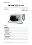
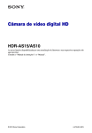
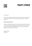
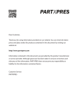
SARAD
GmbH
Analogous Radon Sensor
-1-
User Manual
Analogous Radon Sensor
(Indoor Air Sensor / Soil Gas Sensor)
Version 12/2007
SARAD GmbH
Wiesbadener Straße 10
D-01159 Dresden
GERMANY
Tel.: +49 (0)351 / 6580712
FAX: +49 (0)351 / 6580718
e-mail: [email protected]
Internet: www.sarad.de
Important hint
The unit contains touchable parts which are biased with a high voltage even if the
power supply has been interrupted. This can cause a dangerous electrical shock. Only
skilled personnel trained in handling this type of equipment should open the
enclosure.
Content
Common................................................................................................................................ 2
Theory of Operation .............................................................................................................. 2
Analogous Outputs................................................................................................................ 4
Defining the Measurement Range ..................................................................................... 4
Connecting the analogous outputs to a data acquisition system ........................................ 5
Voltage output configuration .......................................................................................... 5
Current output configuration .......................................................................................... 5
Test Function..................................................................................................................... 6
Digital Output ........................................................................................................................ 6
Alarm Output ..................................................................................................................... 6
Pulse Output...................................................................................................................... 7
Test Function..................................................................................................................... 8
Serial Interface (RS232) ........................................................................................................ 8
Internal Data Logger.............................................................................................................. 8
Starting and Stopping a Measurement .................................................................................. 9
Power Supply ........................................................................................................................ 9
Connectors...........................................................................................................................10
Indoor Air Sensor..............................................................................................................10
Electronic Box for Soil Gas Probe.....................................................................................11
Technical data......................................................................................................................12
Manual_AnalogousRadonSensor_EN_05-12-07.doc
SARAD
GmbH
Analogous Radon Sensor
-2-
Common
The Analogous Radon Sensor converts a measured Radon or Thoron concentration into an
analogous signal with a span of either 0 to 1 V or 0 to 20 mA. The measurement range can
be matched to the local requirements by software. A programmable digital switch output can
be used as an alarm switch or a nuclide selective pulse (counting) output. If the pulse output
is used to determine the concentration values, the analogous outputs can be programmed to
provide the signals of the internal Temperature and Humidity sensor. The variable signal
routing opens a wide range of possibilities for the interconnection of the Analogous Radon
Sensor with external data acquisition and control systems. The unit can be operated as a
“stand alone” Radon monitor due to its internal data logger and the serial interface.
The unit is shipped with the latest release of the Radon Vision software. Please read the
related chapters of software manual.
Theory of Operation
Radon and Thoron will enter the high voltage biased measurement chamber by diffusion
and/or pumping. The daughter nuclides Po-218 and Po-216 generated by the Radon/Thoron
decay inside the chamber are ionised for a short time. These ions are collected by the
electrostatic field on the surface of a semiconductor detector. The decay events of Po218/Po-216 and also those of all following daughter products of the Radon/Thoron decay
chain will be counted by the detector. The detector electronics provide voltage pulses; the
pulse height is proportional to the different emission energy of the single nuclides. A
subsequent multi-channel analyser (MCA) records the frequency distribution (alpha
spectrum) of the detected decays respective their emission energy.
Serial Interface (RS232)
HV BIAS
TX
Radon Chamber
MCA
rH/T
Gauge
Data Memory
(non volatile)
Power Supply
Microprocessor
Diffusion Chamber
RX
PUMP
Digital Output
DAC 1
D
A
DAC 2
D
Real Time Clock
A
Fig. 1 Block diagram Indoor Air Sensor (with internal pump option)
Manual_AnalogousRadonSensor_EN_05-12-07.doc
Analogous Output 1
Analogous Output 2
GmbH
Analogous Radon Sensor
SUB-D9
SARAD
Cable Connection up to 10 m
-3-
Serial Interface (RS232)
RX
MCA
Radon
Chamber
Power Supply
Data Memory
(non volatile)
Microprocessor
HV BIAS
Soil Gas Probe
7-pin CA
Electronic Box
TX
Digital Output
DAC 1
D
A
DAC 2
D
Real Time Clock
Analogous Output 1
Analogous Output 2
A
rH/T Sensor
Fig. 1b Block diagram of the Soil Gas Sensor (soil probe and electronic unit separated)
Five separate energy intervals (Region of Interest = ROI) are defined within the alpha
spectrum to cover the single daughter products. The assignments are given in the table
below:
ROI1 Po-210
ROI2 Po-218
ROI3 Po-216
ROI4 Po-214
ROI5 Po-212
The limits of each ROI are defined by a lower and an upper channel within the alpha
spectrum. The limits have been determined during the energy calibration by the
manufacturer. The calculation of the concentration values of Radon and Thoron are based
on the number of detected decay events within a pre-defined counting interval (also named
sample or integration interval). For detailed information read the application notes AN-002
and AN-004.
Manual_AnalogousRadonSensor_EN_05-12-07.doc
SARAD
GmbH
Analogous Radon Sensor
-4-
Analogous Outputs
The Analogous Radon Sensor offers two analogous signal outputs which can be factory
configured either as voltage output (0 ... 1V) or current loop (0 ... 20 mA). The signals are
generated by a digital to analogue converter (DAC) with subsequent buffer amplifier. The
DAC resolution is 10 bit resulting in a minimum output step width of 1 mV or 0.02 mA.
The voltage/current values are calculated at the end of each integration interval with respect
to the measured Radon/Thoron concentration and the user defined measurement range.
the output voltage will be changed after completing the current interval and remains at this
level until the subsequent interval has been completed
The instrument offers the possibility to output the Temperature and Humidity signal at the
analogous outputs instead of the concentration values. The table below shows the
assignment of the output channels.
rH/T setting
Analogous Output 1
Analogous Output 2
rH/T output disabled
Radon Concentration
Thoron Concentration
rH/T output enabled
Temperature
relative Humidity
Defining the Measurement Range
To fit the measurement range to the analogous output range, an upper measurement range
limit has to be defined. The lower range limit is always set to zero meaning that 0 Bq/m³
resulting in an output signal of 0 V or 0 mA. The upper limit defines the concentration value
where an output signal of 1 V or 20 mA is generated. The expected signal voltage for a
measured concentration value can be calculated by:
VOUT = measured value * 1 V / upper range limit
or
IOUT = measured value * 20 mA / upper range limit
Example:
5000 Bq/m³ has been defined as upper range limit, the actual reading is 2363 Bq/m³. The
output voltage will be set to:
VOUT = 2363 Bq/m³ * 1 V / 5000 Bq/m³ = 0,473 V
A current output will be set to:
IOUT = 2363 Bq/m³ * 20 mA / 5000 Bq/m³ = 9,45 mA.
Readings above the upper limit generate output levels of 1 V or 20 mA. If the measured
values appear frequently close to the upper limit, the range limit should be extended.
From the start of a new sample until finishing the first integration interval 0 V or 0 mA are
applied to the outputs.
The output ranges for the Temperature and Humidity sensor are fixed:
0 ... 1 V / 0 … 20 mA = 0 ... 50 °C
0 ... 1 V / 0 … 20 mA = 0 ... 100 %rF
Manual_AnalogousRadonSensor_EN_05-12-07.doc
SARAD
GmbH
Analogous Radon Sensor
-5-
Connecting the analogous outputs to a data acquisition system
Voltage output configuration
The output impedance of the buffer amplifier is approximately 50 Ohm. Therefore, the input
impedance of the connected signal input should not be lower than 10 kOhm. If longer signal
wires are used, the power supply grounds of the Analogous Radon Sensor and the data
acquisition system should be galvanically isolated by a transformer or by an isolated DC/DC
converter.
Radon Sensor
Data Acquisition System
VIN
0 ... 1V
VOUT
V
DAC
GND
min.
10 kOhm
GND
Fig. 2 Connection to a 0 ... 1 V input
Current output configuration
The maximum driving voltage of the current loop is 4.5 V. To get the full signal range, the
connected load resistance must not exceed the value of 225 Ohm.
Case 1 Connection to a galvanic (e.g. optical) isolated current input:
Radon Sensor
Data Acquisition System
IIN+
IOUT+
VDAC
IINIOUT-
isolated input
GND
50 Ohm
GND
Fig. 3 Connection to an isolated 0 ... 20 mA input
Case 2 Connection to a voltage input using a conversion resistor:
Radon Sensor
Data Acquisition System
IOUT+
VIN
RC max.
225 Ohm
VDAC
IOUT-
GND
GND
GND
VIN = R C* I
50 Ohm
Fig. 4 Connecting the current loop to a voltage input
Manual_AnalogousRadonSensor_EN_05-12-07.doc
SARAD
GmbH
Analogous Radon Sensor
-6-
The galvanic isolation of the ground potential (GND) of the Analogous Radon Sensor and the
data acquisition system is strictly required in case 2. The voltage span can be defined by the
value of the conversion resistor RC (max. 225 Ohm) following Ohm’s law: RC = E / I.
Example:
The desired input voltage for a 20 mA full scale output signal shall be 4 V:
R = 4 V / 20 mA = 200 Ohm
Test Function
This feature allows the operator to apply a user defined voltage (0 ... 1000 mV) to the
analogous outputs by the PC-software. It may be very helpful to check the signal flow
without Radon atmosphere if the sensor is used in complex data acquisition systems. If the
outputs are configured as current loops, the desired current values have to be converted into
their voltage equivalents first (the software will accept voltage values only, e.g. 10 mA 500mV). The test function is only available if a running measurement has been stopped
before.
Digital Output
The driver stage of the digital output consists of an N-channel FET with an inserted pull-up
resistor of 10 kOhm, this is tied to the internal supply voltage of 5 Volts (figure). This allows
connection of the output directly to the TTL/CMOS inputs of a subsequent data acquisition
system. The signal is active LOW. That means, if the output is active the terminal is tied to
ground potential (GND).
Radon Sensor
Data Acquisition System
+5V
10kOhm
TTL IN
min.
100kOhm
DOUT
GND
GND
Fig. 5 Connection to a TTL/CMOS input
The digital output can be programmed by software either as an alarm switch or as a nuclide
sensitive pulse output.
Alarm Output
The output becomes active if the measured concentration value exceeds a user defined alert
level. The output remains active until the concentration drops below this level for at least one
sample interval. If a relay is to be connected directly to the output, the applied coil voltage
has to be less than or equal to 5 Volts. If higher coil voltages are required the internal pull-up
resistor has to be removed by the manufacturer. A recovery diode has to be connected in
parallel with the relay coil (figures below).
Manual_AnalogousRadonSensor_EN_05-12-07.doc
SARAD
GmbH
Analogous Radon Sensor
-7-
The maximum sink current is 50 mA, the maximum applied voltage to the output terminal is
15 Volts.
+5V max.
Radon Sensor
+5V
10kOhm
DOUT
GND
Fig. 6 Direct 5V relay connection
+15V max.
Radon Sensor
+5V
DOUT
GND
Fig. 7 Connecting a relay with higher coil voltage than 5V
The alert output offers a simple way to detect a temporary range overflow. If the alert level is
set to the same value ie the upper limit of the measurement range. The output then becomes
active (LOW) as soon as the concentration exceeds the given limit. The output signal can
then be connected to an additional input of the data acquisition system.
Pulse Output
The usage of the pulse output for the Radon/Thoron measurement is recommended if
concentration changes over few magnitudes of order are expected. If the analogous signal is
to be used, then the upper range limit has to be set to the maximum expected concentration
value. Because of the limited output step width (1024 steps), small concentration changes
would become invisible.
Example:
The maximum expected Radon concentration is around 900 kBq/m³. The upper range limit
has to be set at least to 1000 kBq/m³. If now appear low concentrations, say below 1000
Bq/m³, a change from 600 Bq/m³ to 800 Bq/m³ can not be detected.
Further advantages of the pulse output are the direct information about the counting statistics
(related to the statistical error) and the possibility to use the analogous outputs to log the
Temperature and Humidity simultaneously.
The decay events of the single nuclides can be masked for the pulse output using the five
assigned ROI. Each ROI can be enabled/disabled independently by software (see manual
Radon Vision). All enabled ROI’s are logical “AND” gated. Then the decay of different nuclide
results are in an output pulse. The TTL/CMOS output pulses (HIGH-LOW-HIGH) will be
present for only a few Microseconds after the decay event. The pulse width is approximately
Manual_AnalogousRadonSensor_EN_05-12-07.doc
SARAD
GmbH
Analogous Radon Sensor
-8-
16 microseconds. Take care with the input capacitance (including cable) of the data
acquisition system. Values higher than 300 pF together with the internal 10 kOhm pull-up
resistor result in flat signal slopes.
The Radon concentration is linearly proportional to the number of detected decay events of
the Po-218 (ROI2) and the Po-214 (ROI4).
The Thoron concentration is linearly proportional to the number of detected Po-216 decays
(ROI3).
The calculation procedures are shown in the table below:
ROI1 ROI2 ROI3 ROI4 ROI5 Value
X
Radon (fast)
X
X
Radon (slow)
X
Radon (Po-214 only)
X
Thoron
Calculation
CRn (fast) = N / (T * Sfast)
CRn (slow) = N / (T * Sslow)
CRn(Po-214) = N / (T *(Sslow – Sfast))
CTn = N / (T * SThoron)
X
ROI disabled
ROI enabled
N
T
S
Number of counts detected within all enabled ROI
Time period used for counting
Sensitivity (calibration constant stated within the calibration certificate)
In mixed atmospheres (both, Radon and Thoron are present) an influence of each value to
the other is given. In this case only the Po-214 (ROI4) should be used to calculate the Radon
concentration (third line in the table). For additional information read the application note
AN-004.
Test Function
For signal flow check, the digital output can be activated/deactivated by software. The test
function is only available if a running measurement has been stopped before.
Serial Interface (RS232)
The serial interface allows operation parameters to be adjusted and to download the data
stored by the internal data logger. This offers the possibility of getting the actual readings
while the measurement is still running. All necessary functions for this are provided by the
PC software. The simple binary transfer protocol will be forwarded on request.
Internal Data Logger
The time distributions of Radon and Thoron as well as Temperature and Humidity are
recorded and stored by the internal data logger. In addition the alpha spectrum of the whole
measurement period is available. The time distribution is stored in a non-volatile memory
while the sum spectrum is lost in the event of a power interruption. The memory allows
storage of up to 344 records. If this limit is reached, the data logging will be stopped
automatically. The functions of the analogous and digital outputs are not affected. The data
can be read from the logger after stopping the sample by software control. After starting a
new measurement, the older data will be overwritten if the first integration interval has been
Manual_AnalogousRadonSensor_EN_05-12-07.doc
SARAD
GmbH
Analogous Radon Sensor
-9-
completed. Repeating a data download is possible by stopping the measurement again
during this period. The alpha spectrum will still be lost because it contains counts already
detected since restarting.
Starting and Stopping a Measurement
The measurement starts automatically once a supply voltage has been applied to the unit.
The operation parameters will remain unchanged because they are stored in a non-volatile
memory. This ensures the restart of the system in the event of an unintended power
interruption without any external intervention. The measurement has to be stopped to use
the test functions, download the data, or if operation parameters are to be changed.
Following that, the measurement has to be started again by a short power interruption or by
the software. The internal real time clock is not buffered and will loose its data after power
interruptions. This is not a problem if only the analogous/digital outputs are used. In this
case, the time synchronisation is provided by the subsequent data acquisition system. Be
careful if the internal data logger is to be used. Set the time first and then start a
measurement, both functions are altered via Radon-Vision software. Failure to set the time
will result in the stored time distribution always starting at January 1st 2000.
Power Supply
The Analogous Radon Sensor accepts supply voltages between 11.2 and 15 Volts. This
allows the usage of an AC/DC adapter as well as a 12 V lead acid battery. The total current
consumption is less than 100 mA including 2 x 20 mA for the analogous signal currents. A
galvanic isolation of the Analogous Radon Sensor from the power line and from the data
acquisition system is always recommended. It is strictly required if the outputs are
configured as current loop and connected to the ground potential of the data acquisition
system (e.g. if a conversion resistor is used). This isolation avoids ground loops in the event
of voltage outputs which can shift the analogous signal levels, especially if long signal cables
are used.
Mains Power
P
N
AC
GND
11.2 ... 15VDC
DC
IOUT+/VOUT
Data Acquisition System
IN
IOUT-/GND
Radon Sensor
GND
Fig. 8 Simple galvanic isolation of the Analogous Radon Sensor
Manual_AnalogousRadonSensor_EN_05-12-07.doc
SARAD
GmbH
Analogous Radon Sensor
- 10 -
Connectors
The Analogous Radon Sensor provides four connectors. The figures show the front view of
the connectors. The pin assignment is stamped into the plastic housing of the sockets.
Two different types of connectors (Hirschmann or Binder) are used depending on the product
version.
Indoor Air Sensor
Manufacturer: HIRSCHMANN series CA (IP67)
Power supply (four pin wall mounted male connector)
1 GND
2 Supply voltage (11.2 to 15 Volts)
3 not connected
4 not connected
3
2
1
Serial interface (7-pin wall mounted male connector)
1 GND
2 RS232 TX (transmitter output of the Analogous Radon Sensor)
3 RS232 TX (receiver input of the Analogous Radon Sensor)
4 not connected
5 not connected
6 not connected
7 not connected
4
3
7
2
1
5
6
Digital output (four pin wall mounted female connector)
1 GND
2 DOUT
3 not connected
4 not connected
3
2
1
Analogous outputs (7-pin wall mounted female connector)
1 Analogous output 1; V_OUT / I_OUT+
2 Analogous output 1; GND / I_OUT –
3 Analogous output 2; V_OUT / I_OUT+
4 Analogous output 2; GND / I_OUT5 not connected
6 not connected
7 not connected
Manual_AnalogousRadonSensor_EN_05-12-07.doc
4
5
6
3
7
2
1
SARAD
GmbH
Analogous Radon Sensor
- 11 -
Electronic Box for Soil Gas Probe
Manufacturer: BINDER series 710
Power supply (two pin female socket)
1 GND
2 Supply voltage (11.2 to 15 Volts)
1
2
Serial interface (four pin female socket)
1 GND
2 RS232 TX (transmitter output of the Analogous Radon Sensor)
3 RS232 RX (receiver input of the Analogous Radon Sensor)
4 not connected
2
3
1
4
Digital output (three pin female socket)
1 GND
2 DOUT
3 not connected
2
1
3
Analogous outputs (five pin female socket)
1 Analogous output 1; V_OUT / I_OUT+
2 Analogous output 1; GND / I_OUT –
3 Analogous output 2; V_OUT / I_OUT+
4 Analogous output 2; GND / I_OUT5 not connected
Manual_AnalogousRadonSensor_EN_05-12-07.doc
3
2
4
1
5
SARAD
GmbH
Analogous Radon Sensor
- 12 -
Technical data
Theory of operation
High voltage biased chamber with semiconductor detector
Sampling
Diffusion through a large area 125µm silicon rubber membrane
internal sealed air loop, optionally driven by a pump
Sensitivity
Indoor Air Sensor
Soil Gas Probe
typical 3.1/6.5 counts/min @ 1000 Bq/m³ (fast/slow)
typical 0.8/1.8 counts/min @ 1000 Bq/m³ (fast/slow)
Response time (125µm silicon membrane)
Indoor Air Sensor
30/150 Minutes (fast/slow) with pump option
Soil Gas Probe
60/180 Minutes (fast/slow)
Range
Radon
Temperature
Humidity
Enclosure
Indoor Air Sensor
Material
Dimensions
Weight
Soil Gas Sensor
Material
Dimensions
Weight
0 ... 10 MBq/m³
0 ... 50 °C
0 ... 100%
Aluminium (powder coated), wall mounting possible
280 mm x 230 mm x 111 mm (W x H x D)
approx. 4000 g
Electronic box Aluminium (powder coated)
Soil Gas Probe stainless steel and Acetal
Electronic box 175 mm x 57 mm x 32 mm (W x H x D)
Probe 76.1 mm dia. x 125 mm
Electronic box approx. 250 g
Probe approx. 650 g
Integration interval
1 ... 255 Minutes adjustable in 1 Minute steps
Radon calculation
Alpha spectroscopy
Memory
344 data records and sum spectrum, non-volatile
Interface
Analogue
either 2 x 0 ... 1 V or 0 ... 20 mA (1024 steps)
either Radon/Thoron OR Temperature/Humidity
upper range value programmable
for detailed electrical specifications see manual
Digital
Open drain with internal pull-up resistor (TTL/CMOS)
Alert switch OR direct output of decay pulses
for detailed electrical specifications see manual
Serial
115200 baud, 8N1, only RXD, TXD and GND are used
Power supply
11.2 ... 15 VDC, < 100 mA
Software
Radon Vision
Manual_AnalogousRadonSensor_EN_05-12-07.doc