1
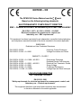
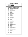
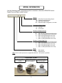
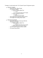
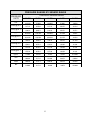
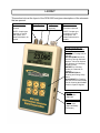
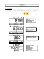
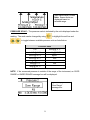
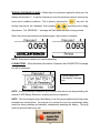
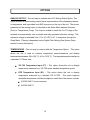
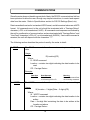
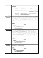
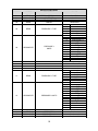
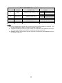
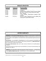
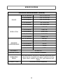
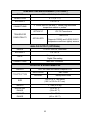
HIGH PRECISION / RESOLUTION DIGITAL PRESSURE METERS DPM-2300 SERIES USER MANUAL BC BIOMEDICAL DPM-2300 SERIES TABLE OF CONTENTS WARNINGS, CAUTIONS, NOTICES ............................................................................. ii DESCRIPTION .............................................................................................................. 1 LAYOUT ......................................................................................................................... 7 SCREENS ...................................................................................................................... 8 KEYS............................................................................................................................ 13 OPTIONS ..................................................................................................................... 15 COMMUNICATIONS .................................................................................................... 16 MANUAL REVISIONS .................................................................................................. 21 LIMITED WARRANTY ................................................................................................. 21 SPECIFICATIONS ....................................................................................................... 22 NOTES ......................................................................................................................... 25 i WARNING - USERS The DPM-2300 is for use by skilled technical personnel only. WARNING - USE The DPM-2300 is intended for testing only and should never be used in diagnostics, treatment or any other capacity where it would come in contact with a patient. WARNING - CONNECTIONS All connections to patients must be removed before connecting the DUT to the DPM-2300. A serious hazard may occur if the patient is connected when testing with the DPM-2300. CAUTION - MODIFICATIONS The DPM-2300 is intended for use within the published specifications. Any application beyond these specifications or any unauthorized user modifications may result in hazards or improper operation. CAUTION - SERVICE The DPM-2300 is intended to be serviced only by authorized service personnel. Troubleshooting and service procedures should only be performed by qualified technical personnel. CAUTION - INSPECTION The DPM-2300 Series Meters should be inspected before each use for wear and the Meter should be serviced if any parts are in question. ii CAUTION - CLEANING Do not immerse. The Meter should be cleaned by wiping gently with a damp, lint-free cloth. A mild detergent can be used if desired. CAUTION - LIQUIDS Do not submerge or spill liquids on the DPM2300. Do not operate the DPM-2300 if it may have been exposed to fluid. CAUTION - ENVIRONMENT Exposure to environmental conditions outside the specifications can adversely affect the performance and accuracy of the DPM-2300. If the unit is outside the Operating Specifications, allow it to acclimate to specified conditions for at least 30 minutes before attempting to operate it. CAUTION – MEDIA COMPATIBILITY The DPM-2300 is intended to be used with only non-corrosive, non-ionic, or otherwise pure fluids and/or gases that are compatible with sensor materials including glass, silicon, ceramic, epoxy, RTV, gold, aluminum and nickel. iii NOTICE – CE The DPM-2300 Series Meters bear the mark Based on the following testing standards: ELECTROMAGNETIC COMPATIBILITY DIRECTIVE EMC – Directive 89/336/EEC as amended by 92/31/EEC and 93/68/EEC EN 61326-1:1997 + A1:1998 + A2:2001 + A3:2003 “Electrical equipment for measurement, control and laboratory use – EMC requirements” This equipment has been type tested by an independent, accredited testing laboratory and compliance was demonstrated to the above standard to the extent applicable. EMISSIONS Radiated and Line Conducted Emissions EN 61000-3-2:2000 EN 61000-3-3:1995 + A1:2001 Harmonic Current Emissions Voltage Fluctuation and Flicker IMMUNITY– CLASS C EN 61000-4-2:1995 + A1:1998 + A2:2001 EN 61000-4-3:2002 EN 61000-4-4:1995 + A1:2001 + A2:2001 EN 61000-4-5:1995 + A1:2001 EN 61000-4-6:1996 + A1:2000 EN 61000-4-11:1994 + A1:2001 Electrostatic Discharge Radiated Electric Field Immunity Electrical Fast Transients / Bursts Surge Voltage Conducted Disturbance Voltage Dips and Short Interrupts LOW VOLTAGE DIRECTIVE EC – Directive 73/23/EC EN 61010-1:2001 “Safety requirements for electrical equipment for measurement, control, and laboratory use – General requirements” This equipment has been type tested and compliance was demonstrated to the above standard to the extent applicable. iv NOTICE – SYMBOLS Symbol Description Center Negative NOTICE – ABBREVIATIONS ANSI ASCII BCD C cmH20 ° DUT DC American National Standards Institute American Standard Code for Information Interchange Binary Coded Decimal Celsius centimeters of water degree(s) Device Under Test Direct Current Euro European F Fahrenheit FS inHg inH20 kg 2 kg/cm Full Scale inches of mercury inches of water kilogram(s) kilogram(s) per centimeter squared kHz kilohertz kPa kilopascal(s) Max Maximum µA microampere(s) mA milliampere(s) mBar mm mmHg Min NEDA milliBar(s) millimeter(s) millimeter(s) of mercury Minimum National Electronic Distributors Association Lbs pounds PSI pounds per square inch Pres Pressure RH RTD s Temp USA V VDC Relative Humidity Resistive Thermal Device second(s) Temperature United States of America Volt(s) Volt(s) Direct Current v NOTICE – DISCLAIMER BC GROUP INTERNATIONAL, INC. WILL NOT BE RESPONSIBLE FOR ANY INJURIES SUSTAINED DUE TO UNAUTHORIZED EQUIPMENT MODIFICATIONS OR APPLICATION OF EQUIPMENT OUTSIDE OF THE PUBLISHED INTENDED USE AND SPECIFICATIONS. NOTICE – DISCLAIMER BC GROUP INTERNATIONAL, INC. RESERVES THE RIGHT TO MAKE CHANGES TO ITS PRODUCTS OR SPECIFICATIONS AT ANY TIME, WITHOUT NOTICE, IN ORDER TO IMPROVE THE DESIGN OR PERFORMANCE AND TO SUPPLY THE BEST POSSIBLE PRODUCT. THE INFORMATION IN THIS MANUAL HAS BEEN CAREFULLY CHECKED AND IS BELIEVED TO BE ACCURATE. HOWEVER, NO RESPONSIBILITY IS ASSUMED FOR INACCURACIES. NOTICE – CONTACT INFORMATION BC BIOMEDICAL BC GROUP INTERNATIONAL, INC. 3081 ELM POINT INDUSTRIAL DR. SAINT CHARLES, MO 63301 USA 1-800-242-8428 1-314-638-3800 www.bcgroupintl.com [email protected] DPM-2300 Series User Manual www.bcgroupintl.com 07/12 Copyright © 2012 Made in the USA Rev 06 vi BC BIOMEDICAL DPM-2300 SERIES DIGITAL PRESSURE METERS The Model DPM-2300 Series is a family of microprocessor-based, high-precision Pressure Meters, which are intended for use in the evaluation and servicing of a wide variety of medical, commercial and industrial applications. These meters measure compatible gas and liquid pressures in various engineering units. Available optional features include a RS232 port for remote control and data collection, a DC analog output option, and an optional temperature sensor input (either YSI 700 Series or 100 Ω RTD Probe). The following are highlights of the main features: DPM-2301 (Basic Features): GRAPHICAL LCD DISPLAY WITH CURSOR SELECTION OF OPTIONS AND SETUP OF PARAMETERS ± 0.05% FS PRESSURE ACCURACY DIGITAL CALIBRATION AND ZERO OFFSET ADJUSTMENT – NO POTS TO TURN 24 BIT MEASUREMENT PROGRAMMABLE DIGITAL FILTER 13 ENGINEERING UNITS: PSI mmHg @ 0 °C inH2O @ 4 °C mmHg @ 20 °C inH2O @ 20 °C kg/cm2 inH2O @ 60 °F kPa cmH2O @ 20 °C mBar inHg @ 0 °C Bar inHg @ 20 °C SELECTABLE DISPLAY OPTIONS AND DIGIT SIZES BATTERY LIFE DISPLAY (0 to 100%) SOFTWARE-ADJUSTABLE DISPLAY CONTRAST MAX and MIN PRESSURE VALUE CAPTURE AND STORAGE DPM-2302 MODEL ADDS: RS-232 SERIAL COMMUNICATIONS SECOND PRESSURE SENSOR ADDS: INDEPENDENT PRESSURE CHANNEL SEPARATE AND COMBINED DISPLAY OPTION ANALOG OUTPUT OPTION (OPTION DC) ADDS: OPTION DC - DC ANALOG OUTPUT (REFRESH RATE DEPENDENT UPON DIGITAL FILTER SETTING) BNC OUTPUT CONNECTOR ± 0.1% FS ACCURACY 1 TEMPERATURE OPTION ADDS: OPTION Y7 - YSI 700 TEMPERATURE PROBE INTERFACE OPTION R1 - 100 Ω RTD TEMPERATURE PROBE INTERFACE -20.0 TO 100.0 °C / -4.0 TO 212.0 °F TEMPERATURE RANGE ± 0.5% FS ACCURACY MAX and MIN TEMPERATURE VALUE CAPTURE AND STORAGE OPTIONAL ACCESSORIES: BC20-21100 BATTERY ELIMINATOR (USA Version) BC20-21101 BATTERY ELIMINATOR (Euro Version) BC20-41337 RS-232 COMMUNICATIONS CABLE (7PIN MINI-DIN TO DB-9F) BC20-41339 USB COMMUNICATIONS ADAPTER (DB-9M TO USB-A) FOR USE WITH BC20-41337 BC20-30106 SOFT-SIDED CARRYING CASE BC20-01005 UNIVERSAL MANOMETER (PRESSURE) ADAPTER KIT BC20-01006 YSI 700 TEMPERATURE PROBE BC20-01008 RTD (100 Ω) TEMPERATURE PROBE 2 MODEL INFORMATION Use the following model configuration guide to construct or decode a DPM-230X series Digital Pressure Meter model number: DPM 230X X X X X Options DC FC MC Sxx = = = = DC (Direct Current) Analog Output Female Quick-Disconnect Male Quick-Disconnect Special Coupler Configuration, see table Temperature Sensor Option N = Not Applicable Y7 = YSI 700 R1 = 100 Ω RTD Pressure 2 Range (Left Port) N = Not Applicable 100 = Max 100 PSI (Default Quick-Disconnect) 75 = Max 75 PSI (Default Quick-Disconnect) 10 = Max 10 PSI (Default Male Luer Lock) 5 = Max 5 PSI (Default Male Luer Lock) .3 = Max 0.3 PSI (Default Male Luer Lock) Pressure 1 Range (Right Port) 100 = Max 100 PSI (Default Quick-Disconnect) 75 = Max 75 PSI (Default Quick-Disconnect) 10 = Max 10 PSI (Default Male Luer Lock) 5 = Max 5 PSI (Default Male Luer Lock) .3 = Max 0.3 PSI (Default Male Luer Lock) Model 2301 = Basic Model 2302 = Adds RS-232 Note: The FC or MC options are not applicable when the “–Sxx” option is specified. COUPLER TYPES MALE LUER LOCK FEMALE QUICKDISCONNECT 3 MALE QUICKDISCONNECT Example model numbers: DPM-23017510NFC o Model DPM-2301 (Basic Model) o Two Pressure Ranges: Pressure 1 Range (Right Port): 75 PSI Female Quick-Disconect Coupler Pressure 2 Range (Left Port): 10 PSI Male Luer Lock Coupler o Not equipped with Temperature Sensor Option o Not equipped with Analog Output Option DPM-230210075Y7DCFC o Model DPM-2302 (Basic Model plus RS-232) o Two Pressure Ranges: Pressure 1 Range (Right Port): 100 PSI Female Quick-Disconnect Coupler Pressure 2 Range (Left Port): 75 PSI Female Quick-Disconnect Coupler o YSI 700 Series Temperature Sensor Option o DC Analog Output Option For additional coupler options, the “-Sxx” Special Coupler Configurations option overrides default coupler options to those listed in the following table: SPECIAL COUPLER CONFIGURATIONS Option Pressure 1 Coupler (Right Port) Pressure 2 Coupler (Left Port) S01 S02 S03 S04 S05 S06 S07 S08 S09 S10 S11 S12 Female Quick-Disconnect Female Quick-Disconnect Female Quick-Disconnect Female Quick-Disconnect Male Quick-Disconnect Male Quick-Disconnect Male Quick-Disconnect Male Quick-Disconnect Male Luer Lock Male Luer Lock Male Luer Lock Male Luer Lock Female Quick-Disconnect Male Quick-Disconnect Male Luer Lock Not Applicable Female Quick-Disconnect Male Quick-Disconnect Male Luer Lock Not Applicable Female Quick-Disconnect Male Quick-Disconnect Male Luer Lock Not Applicable 4 Examples of model numbers with “-Sxx” Special Coupler Configurations option: DPM-2301105NS03 o Model DPM-2301 (Basic Model) o Two Pressure Ranges: Pressure 1 Range (Right Port): 10 PSI Female Quick-Disconnect Coupler Pressure 2 Range (Left Port): 5 PSI Male Luer Lock Coupler o Not equipped with Temperature Sensor Option o Not equipped with Analog Output Option DPM-230210NY7DCS08 o Model DPM-2302 (Basic Model plus RS-232) o One Pressure Range: Pressure 1 Range (Right Port): 10 PSI Female Quick-Disconnect Coupler Not equipped with Pressure 2 Range o YSI 700 Series Temperature Sensor Option o DC Analog Output Option 5 PRESSURE RANGES BY SENSOR RANGE PRESSURE UNITS PSI mmHg @ 0° C mmHg @ 20° C inHg @ 0° C inHg @ 20° C cmH2O @ 20° C inH2O @ 4° C inH2O @ 20° C inH2O @ 60° F kg/cm 2 kPa mBar Bar PRESSURE SENSOR RANGE 100 PSI 75 PSI 10 PSI 5 PSI 0.3 PSI -13.500 to 100.000 -698.2 to 5171.5 -700.6 to 5190.3 -27.486 to 203.602 -27.586 to 204.342 -951.8 to 7043.2 -373.6 to 2768.1 -374.3 to 2772.9 -374.1 to 2770.8 -.9491 to 7.0306 -93.08 to 689.48 -930.8 to 6894.8 -.9308 to 6.8948 -13.500 to 75.000 -698.2 to 3878.6 -700.6 to 3892.7 -27.486 to 152.702 -27.586 to 153.256 -951.8 to 5282.4 -373.6 to 2076.1 -374.3 to 2079.7 -374.1 to 2078.1 -.9491 to 5.2730 -93.08 to 517.11 -930.8 to 5171.1 -.9308 to 5.1711 -10.0000 to 10.0000 -517.15 to 517.15 -519.00 to 519.03 -20.3602 to 20.3602 -20.4342 to 20.4342 -704.32 to 704.32 -276.81 to 276.81 -277.29 to 277.29 -277.08 to 277.08 -.70307 to .70307 -68.948 to 68.948 -689.48 to 689.48 -.68948 to .68948 -5.0000 to 5.0000 -258.57 to 258.57 -259.51 to 259.51 -10.1801 to 10.1801 -10.2171 to 10.2171 -352.16 to 352.16 -138.40 to 138.40 -138.64 to 138.64 -138.54 to 138.54 -.35153 to .35153 -34.473 to 34.473 -344.74 to 344.74 -.34474 to .34474 -.30000 to .30000 -15.514 to 15.514 -15.571 to 15.571 -.61081 to .61081 -.61303 to .61303 -21.129 to 21.129 -8.304 to 8.304 -8.319 to 8.319 -8.312 to 8.312 -.021092 to 0.21092 -2.0684 to 2.0684 -20.684 to 20.684 -.020684 to .020684 6 LAYOUT This section looks at the layout of the DPM-2300 and gives descriptions of the elements that are present. Pressure Port #2: Male Luer coupler pictured Analog Output: BNC (Optional) Temperature: ¼” Phone Jack (Optional) NOTE: Coupler type depends on sensor and options, see Model Information for details. Pressure Port #1: Female QuickDisconnect pictured NOTE: Coupler type depends on sensor and options, see Model Information for details. 6 Light Touch Keys for Selecting Parameters and Settings: POWER for Turning Unit On and Off UP and DOWN Arrows for Scrolling Through Selected Options. When No Options are Selected, for Changing Display Screen SELECT for Choosing Setting or Parameter to Change SETUP/RETURN for Entering and Exiting Setup Menu HOLD/RESET for Freezing the Unit at its Current Setting and for Clearing the Min/Max Value in Capture Register RS-232: 7 pin Mini-Din (Optional) Power: 2.1 mm Jack (Optional Battery Eliminator) 7 SCREENS MAIN SCREENS – There can be up to four main screens, depending on the model. They are PRESSURE 1, PRESSURE 2, TEMPERATURE, COMBINED and INPUTS. The available screens can be toggled through using . Pressure Display with Min/Max Option selected Pressure Port 2 Display with Min/Max Option selected Temperature Display with Min/Max Option selected Combined Screen showing: Pressure Port 1 Pressure Port 2 Temperature 8 Input Identification Screen Note: Sensor limits are displayed based on selected range. PRESSURE SCALE – The pressure scale is indicated by the units displayed under the reading. The scale can be changed by using to highlight the unit line and to toggle between available pressure units as listed below. Pressure Units PSI mmHg @ 0 °C inH2O @ 4 °C inH2O @ 20 °C mmHg @ 20 °C kg/cm2 inH2O @ 60 °F kPa cmH2O @ 20 °C mBar inHg @ 0 °C Bar inHg @ 20 °C NOTE: If the measured pressure is outside of the range of the instrument, an OVER RANGE or UNDER RANGE message box will be displayed. Typical display with “Over Range” message box. 9 TEMPERATURE SCALE – The temperature scale is indicated by the units displayed under the reading. The scale can be changed by using to highlight the unit line and to toggle the temperature units between Degrees Celsius (°C) and Fahrenheit (°F). NOTE: If the measured temperature is outside of the range of the instrument, an OVER RANGE or UNDER RANGE message box will be displayed. For models with the YSI option, the NO PROBE message box will be displayed when the unit detects an open connection. For models with the RTD option, the OVER RANGE message box will also be displayed with an open connection. Typical display with “No Probe” message box. NOTE: YSI option only SYSTEM SETUP – The Setup Mode allows the user to adjust the configuration of the meter. The Setup screen can be entered using the changed by using key. The parameters can be to highlight the line and options. The Setup screen can be exited using the 10 to toggle the available key. The following is a breakdown of the parameters available in the configuration of the unit and their available options: System Setup Configuration Parameter Display Min/Max Analog Scale Description Selects whether the Min and Max values will be displayed on the main screens (except COMBINED). Analog Output Scaling voltage. This is the maximum analog output voltage. The output is scaled to this voltage over the positive range of the selected analog source. Analog Source Selects the source reading for the analog output Contrast Adjust Sets the contrast of the display screen. Determines the period of inactivity before the meter is turned OFF. A timer is started when the meter is turned ON and is reset each time a key is pressed. When the timer reaches the value set in this parameter, the power is automatically turned OFF. (NOTE: Setting this parameter to 0 disables the Auto Off timer. When running from line power, the meter does not automatically shut off.) Displays current life of the battery. At 10%, a warning screen will appear. Auto Off Timer Battery Life Beep Length Filter – Pres 1 Filter – Pres 2 Filter – Temp RTD Type (OPTION R1) Software Sets audible beep duration. Determines the number of samples that are averaged in the digital filter. The software has a Digital Filter that averages the readings to produce a stable display. (NOTE: Increasing this setting will cause a more stable display. However, it will also cause a slower response to small changes. The best setting is the smallest number that provides a stable display.) Sets the Temperature Coefficient (alpha) to match that of the RTD probe. Displays current software program. 11 Range yes/no 1.0 to 4.0 Volts Pres1, Pres2, or Temp 0 to 20 0 to 30 Minutes 0 to 100% (Read Only) 0 to 15 0 to 10 Seconds 0.00385/°C or 0.00392/°C (Read Only) ZEROING PRESSURE SCALES – When there is no pressure applied to either port, the display should read “0.” It may be necessary to zero the pressure scales to remove any errors due to ambient conditions. This is done by pressing the zeroing instructions are displayed, then pressing key until the simultaneously to begin the process. The “ZEROING…” message will flash while the scale is being zeroed. When the zeroing instructions are displayed again, the process is complete. NOTE: Each sensor needs to be zeroed separately. LOW BATTERY – When the battery life reaches 10 percent, the LOW BATTERY message box will be displayed. Typical display with “Low Battery” message box. NOTE: A battery eliminator receptacle is provided so that the unit can be powered by the optional 9 VDC Battery Eliminator, enabling continuous operation. NOTE: The unit is shipped with a Red Battery Lock-Out plug installed into the line power receptacle as shown below. Its purpose is to prevent the unit from accidentally being turned on during handling and transport, subsequently depleting the battery. This plug must be removed before any use! 12 KEYS Six tactile-touch keys are provided for system operation: – This key turns the unit off and on. The unit will return to the main screen that was active when it was turned off. – In the DISPLAY MODE, these keys toggle the display through the available main screens. In the SELECT MODE, if a parameter has been highlighted, these keys will scroll through the available settings. – On any screen, there are a number of parameters that may be selected and changed. This key sequences the cursor (Highlight) through those parameters. – This key is used to Hold (freeze) and Reset (unfreeze) any of the input displays. Depressing this key will hold the currently displayed Pressure or Temperature reading until reset. Each input can be held independently. When active, the word “HOLD” is in the display. Depressing this key on a screen that is held will reset that input and remove the word “HOLD” from the display. NOTE: In the composite screen, the hold feature requires that the specific input be selected using before is used. 13 – This key toggles the unit into and out of the Setup Mode. Depressing this key will enter the Setup screen where the configuration can be viewed and adjusted. Depressing the key again will exit the Setup Mode and return to the previously viewed main screen. This will also save any changes to the internal EEPROM memory so they will be retained even with the power turned off or battery removed. 14 OPTIONS ANALOG OUTPUT – The unit may be ordered with a DC Analog Output Option. This option provides a filtered analog output that is representative of the displayed pressure or temperature, and is provided via a BNC connector on the top of the unit. The source parameter for the analog output is selectable in the Setup Menu between Pressure (Pres) or Temperature (Temp). The output is scaled to match the 0 to FS range of the selected source parameter over a variable internally generated reference voltage. This reference voltage is selectable from 1.0 to 4.0 VDC in 0.1 V increments through the Setup Menu. Filtering is dependent on the Digital Filter Setting (See System Setup section for more information). TEMPERATURE – The unit may be ordered with the Temperature Option. This option allows the unit to read an external temperature sensor/transducer and display temperatures between -20 to 100 °C (-4.0 to 212.0 °F). The temperature probe interface is a standard ¼” Phone Jack. YSI 700 Temperature Input (Y7) – This option allows the unit to display temperature measured by a YSI 700 series standard temperature probe. RTD Temperature Input (R1) – This option allows the unit to display temperature measured by a standard 100 Ω RTD. This option supports selectable temperature coefficients (alpha) to match that of the sensor or probe: 0.00385 Ω/Ω/°C (most common) 0.00392 Ω/Ω/°C 15 COMMUNICATIONS Since the meter does not handle a great deal of data, the RS-232 communications link has been optimized to allow the user, through very simple instructions, to control and request data from the meter. Refer to Specifications section for RS-232 Settings (Baud, etc). Data transmitted/received is in standard ASCII format, and all numerical values are in BCD format. All commands sent to the unit should be terminated with a “Carriage Return” character (<CR> or in hexadecimal, 0x0D). All commands and responses are echoed by the unit for confirmation of communication, and are terminated with “Carriage Return” and “Line Feed” characters (<CR><LF> or in hexadecimal, 0x0D0A). If an invalid command is received, the unit will respond with the characters “??”. The following section describes the protocol used by the meter in detail: R - READ The READ command allows the user to read system settings and data. Usage: R(Location)(CR) Where: R - READ command Location - contains two digits indicating the data location to be read CR - Carriage Return Example: Data Sent R08<CR> W - WRITE Data Returned R08<CR><LF> 10.25 mmHg<CR><LF> Meaning Echo of Command Sent 10.25 mmHg measured The WRITE command allows the user to update the system settings. Usage: W(Location – 2 digits)(Data – 5 digits)(CR) Where: W - WRITE command Location - contains two digits indicating the data location to be written Data – five-digit field containing the data to be written at the Location set above CR - Carriage Return 16 Examples: Data Sent W064<CR> Data Returned W064<CR><LF> W0600004<CR> W0600004<CR><LF> W05100<CR> ??<CR><LF> U - UPLOAD Meaning Echo of Command Sent (Set Pressure units to “inH2O”) Echo of Command Sent (Set Pressure units to “inH2O”) W05100<CR><LF> Echo of Command Sent Invalid Command Response (Location 05 is Read Only) The UPLOAD command allows the user to read all of the selected device data from locations 1 through 16 with a single command. The data returned will be formatted as a single block per location separated by a carriage return, line feed character sequence (CRLF – equivalent to hexadecimal 0x0D0A). See the table below for details on the data structure. Usage: U(CR) Where: U – UPLOAD command CR - Carriage Return Q - QUICKSEND QUICKSEND is a feature that allows the user to receive an automatic update of all of the meter data without any further user interaction. When the QUICKSEND command is received, the feature is turned ON and the meter will automatically send all of the device data every half second. The Quicksend feature is toggled ON and OFF with the QUICKSEND command. See the table below for details on the data structure. Usage: Q(CR) Where: Q – QUICKSEND command CR - Carriage Return V - VERSION The VERSION command allows the user to read the Software Version that the unit is currently running. Usage: V(CR) Where: V – VERSION command CR - Carriage Return 17 X - CANCEL The CANCEL command is simply a way to re-establish proper control, should a communications error occur or an incorrect command be transmitted. For the most part, an incorrect command will simply be ignored and the meter will return to listening for future commands. However, a prior command may be cancelled midstream by transmitting the CANCEL command anytime. Usage: X This command does not require a carriage return, nor will it acknowledge with a carriage return. However, it will echo an ‘X’ character to indicate that the CANCEL command has been received. NOTE: The VERSION or CANCEL commands may also be utilized as an acknowledgement of the meter being on line. 18 DATA LOCATIONS LOCATION ACCESS DESCRIPTION RANGE 01 02 03 READ READ/WRITE READ/WRITE BATTERY LIFE REMAINING CONTRAST AUTO POWER OFF 0 to 100% 0 to 20 0 to 30 (seconds) 04 READ MODEL RESERVED 05 READ PRESSURE 1 TYPE 06 READ/WRITE PRESSURE 1 UNITS 07 08 09 10 READ/WRITE READ READ/WRITE READ/WRITE PRESSURE 1 FILTER PRESSURE 1 PRESSURE 1 MAX PRESSURE 1 MIN 11 READ PRESSURE 2 TYPE 12 READ/WRITE PRESSURE 2 UNITS 13 14 15 16 READ/WRITE READ READ/WRITE READ/WRITE PRESSURE 2 FILTER PRESSURE 2 PRESSURE 2 MAX PRESSURE 2 MIN 19 1 2 3 4 5 0 1 2 3 4 5 6 7 8 9 10 11 12 0 1 2 3 4 5 0 1 2 3 4 5 6 7 8 9 10 11 12 100 PSI Max 75 PSI Max 10 PSI max 5 PSI max 0.3 PSI max PSI mmHg @ 0 °C mmHg @ 20 °C inHg @ 0 °C inHg @ 20 °C cmH2O @ 20°C inH2O @ 4 °C inH2O @ 20 °C inH2O @ 60 °F 2 kg/cm kPa mBar Bar 0-60 (seconds) See Note 1 See Note 1, 3 See Note 1, 3 Not Applicable 100 PSI Max 75 PSI Max 10 PSI max 5 PSI max 0.3 PSI max PSI mmHg @ 0 °C mmHg @ 20 °C inHg @ 0 °C inHg @ 20 °C cmH2O @ 20°C inH2O @ 4 °C inH2O @ 20 °C inH2O @ 60 °F 2 kg/cm kPa mBar Bar 0-60 See Note 1 See Note 1, 3 See Note 1, 3 DATA LOCATIONS (Temp option only) LOCATION ACCESS DESCRIPTION 17 READ TEMPERATURE SENSOR TYPE 18 READ/WRITE TEMPERATURE UNITS 19 20 21 22 READ/WRITE READ READ/WRITE READ/WRITE TEMPERATURE FILTER TEMPERATURE TEMPERATURE MAX TEMPERATURE MIN RANGE 0 1 2 0 1 Not Applicable YSI 700 RTD 100 °C °F 0-60 See Note 2 See Note 2, 3 See Note 2, 3 NOTES 1. Pressure readings are returned in the currently set Pressure Units parameter in Location 6. This may be changed via the WRITE command or manually via the keys. 2. Temperature readings are returned in the currently set Temperature Units parameter in Location 18. This may be changed via the WRITE command or manually via the keys. 3. MIN/MAX readings may be reset at any time via a WRITE command to either MIN/MAX location, or manually via the keys. 20 MANUAL REVISIONS Revision # Program # Revisions Made Rev 01 Rev 02 Rev 03 Rev 04 Rev 05 DT7321CA DT7321CB DT7321CB DT7321CG DT7321CH Rev 06 DT7321CI Origination Min/Max made standard, Quick-Disconnect added MC and FC option for Quick-Disconnect added Misc. Updates Format Updated, Specifications Updated, Misc. Updates Special Coupler Configurations option added, Max Overpressure Specification added LIMITED WARRANTY WARRANTY: BC GROUP INTERNATIONAL, INC. WARRANTS ITS NEW PRODUCTS TO BE FREE FROM DEFECTS IN MATERIALS AND WORKMANSHIP UNDER THE SERVICE FOR WHICH THEY ARE INTENDED. THIS WARRANTY IS EFFECTIVE FOR TWELVE MONTHS FROM THE DATE OF SHIPMENT. EXCLUSIONS: THIS WARRANTY IS IN LIEU OF ANY OTHER WARRANTY EXPRESSED OR IMPLIED, INCLUDING, BUT NOT LIMITED TO ANY IMPLIED WARRANTY OF MERCHANTABILITY OR FITNESS FOR A PARTICULAR PURPOSE. BC GROUP INTERNATIONAL, INC. IS NOT LIABLE FOR ANY INCIDENTAL OR CONSEQUENTIAL DAMAGES. NO PERSON OTHER THAN AN OFFICER IS AUTHORIZED TO GIVE ANY OTHER WARRANTY OR ASSUME ANY LIABILITY. REMEDIES: THE PURCHASER'S SOLE AND EXCLUSIVE REMEDY SHALL BE: (1) THE REPAIR OR REPLACEMENT OF DEFECTIVE PARTS OR PRODUCTS, WITHOUT CHARGE. (2) AT THE OPTION OF BC GROUP INTERNATIONAL, INC., THE REFUND OF THE PURCHASE PRICE. P:\MANUALS\BCGroup\…\DPM-2000\DPM-2300\DPM2300_UM_Rev06.doc 21 SPECIFICATIONS PRESSURE MEASUREMENT (GAUGE) RANGE RESOLUTION MAXIMUM OVERPRESSURE 100 PSI SENSOR -13.5 TO 100.0 PSI 75 PSI SENSOR -13.5 TO 75.0 PSI 10 PSI SENSOR -10.0 TO 10.0 PSI 5 PSI SENSOR -5.0 TO 5.0 PSI 0.3 PSI SENSOR -0.3 TO 0.3 PSI 100 PSI SENSOR 0.001 PSI 75 PSI SENSOR 0.001 PSI 10 PSI SENSOR 0.0001 PSI 5 PSI SENSOR 0.0001 PSI 0.3 PSI SENSOR 0.00001 PSI 100 PSI SENSOR 200 PSI 75 PSI SENSOR 200 PSI 10 PSI SENSOR 45 PSI 5 PSI SENSOR 15 PSI 0.3 PSI SENSOR 5 PSI ACCURACY ± 0.05% FS DIGITAL FILTER 0 to 10 seconds, Selectable COMPATIBLE MEDIA Only non-corrosive, non-ionic, or otherwise pure fluids and/or gases that are compatible with sensor materials including glass, silicon, ceramic, epoxy, RTV, gold, aluminum and nickel. CONNECTIONS See Model Number Breakdown 22 TEMPERATURE MEASUREMENT (OPTIONAL) RANGE -20.0 to 100.0 °C (-4.0 to 212.0 °F) RESOLUTION 0.1 °C (0.1 °F) ACCURACY ± 0.5% FS CONNECTIONS ¼” Phone Jack for use with ¼” Phone Plug terminated temperature cables or probes. OPTION Y7 TRANSDUCER COMPATIBILITY YSI 700 Transducers 100 Ω RTD OPTION RTD Supports 0.00385 and 0.00392 Ω/Ω/°C temperature coefficient (alpha) sensors ANALOG OUTPUT (OPTIONAL) RANGE 1.0 to 4.0 VDC/FS, Selectable ACCURACY ± 0.1% FS RATE Output dependent on Digital Filter setting CONNECTIONS Male BNC Connector PHYSICAL & ENVIRONMENTAL DISPLAY 128 X 64 Pixels Non-Backlit Graphical LCD ENCLOSURE ABS Plastic OVERLAY Back-printed Lexan CONSTRUCTION SIZE 7.69 x 3.97 x 1.80 Inches (195.3 x 100.8 x 45.7 mm) WEIGHT < 1 Lbs (0.45 kg) OPERATING RANGE 15 to 30 °C (59 to 86 °F) STORAGE RANGE -40 to 60 °C (-40 to 140 °F) 23 ELECTRICAL & MISC. 9V Alkaline Battery (ANSI/NEDA 1604A or equivalent) BATTERY 9 VDC, 200 mA BATTERY ELIMINATOR POWER CONSUMPTION BC20-21100 (USA Version) BC20-21101 (Euro Version) ON < 35 mA OFF < 40 µA CONTINUOUS 80 hours OFF 1 year BAUD 115200 DATA BITS 8 START BITS 1 STOP BITS 1 PARITY None HANDSHAKING None BATTERY LIFE RS-232 COMMUNICATIONS Seven (7) pin Mini-DIN Receptacle Pinout: CONNECTIONS 24 NOTES 25 NOTES 26 BC GROUP INTERNATIONAL, INC. 3081 ELM POINT INDUSTRIAL DRIVE ST. CHARLES, MO 63301 USA 1-800-242-8428 1-314-638-3800 www.bcgroupintl.com [email protected] DPM-2300 Series User Manual 07/12 – Rev 06 Copyright © 2012 Made in the USA