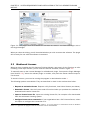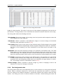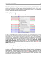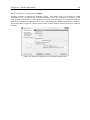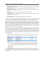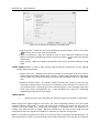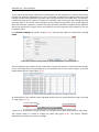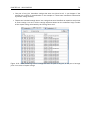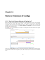
1
CLC Genome Finishing Module
USER MANUAL
User manual for
CLC Genome Finishing Module 1.5.1
Windows, Mac OS X and Linux
August 20, 2015
This software is for research purposes only.
CLC bio, a QIAGEN Company
Silkeborgvej 2
Prismet
DK-8000 Aarhus C
Denmark
Contents
1 Introduction to the CLC Genome Finishing Module
7
1.1 Genome finishing . . . . . . . . . . . . . . . . . . . . . . . . . . . . . . . . . . .
7
1.2 CLC Genome Finishing Module . . . . . . . . . . . . . . . . . . . . . . . . . . . .
7
1.3 Genome finishing and working with shared data . . . . . . . . . . . . . . . . . . .
8
1.4 Latest improvements . . . . . . . . . . . . . . . . . . . . . . . . . . . . . . . . .
9
2 System requirements and installation of the CLC Genome Finishing Module
10
2.1 System requirements . . . . . . . . . . . . . . . . . . . . . . . . . . . . . . . . .
10
2.1.1 Special requirements for Join Contigs . . . . . . . . . . . . . . . . . . . .
10
2.2 How to install a Workbench plugin . . . . . . . . . . . . . . . . . . . . . . . . . .
11
2.3 Workbench Licenses
. . . . . . . . . . . . . . . . . . . . . . . . . . . . . . . . .
12
2.3.1 Request an evaluation license . . . . . . . . . . . . . . . . . . . . . . . .
13
Direct download . . . . . . . . . . . . . . . . . . . . . . . . . . . . . . . .
14
Go to license download web page . . . . . . . . . . . . . . . . . . . . . .
14
Accepting the license agreement . . . . . . . . . . . . . . . . . . . . . . .
15
2.3.2 Download a license using a license order ID . . . . . . . . . . . . . . . . .
16
Direct download . . . . . . . . . . . . . . . . . . . . . . . . . . . . . . . .
16
Go to license download web page . . . . . . . . . . . . . . . . . . . . . .
16
Accepting the license agreement . . . . . . . . . . . . . . . . . . . . . . .
18
2.3.3 Import a license from a file . . . . . . . . . . . . . . . . . . . . . . . . . .
18
Accepting the license agreement . . . . . . . . . . . . . . . . . . . . . . .
18
2.3.4 Configure license server connection . . . . . . . . . . . . . . . . . . . . .
19
Borrowing a license . . . . . . . . . . . . . . . . . . . . . . . . . . . . . .
20
Common issues when using a network license
. . . . . . . . . . . . . . .
21
2.3.5 Download a static license on a non-networked machine . . . . . . . . . . .
22
3
CONTENTS
4
2.4 How to uninstall a Workbench plugin . . . . . . . . . . . . . . . . . . . . . . . . .
24
2.5 How to install a Server plugin . . . . . . . . . . . . . . . . . . . . . . . . . . . . .
24
2.5.1 Static license installation . . . . . . . . . . . . . . . . . . . . . . . . . . .
25
2.5.2 Windows license download . . . . . . . . . . . . . . . . . . . . . . . . . .
26
2.5.3 Mac OS license download . . . . . . . . . . . . . . . . . . . . . . . . . . .
26
2.5.4 Linux license download . . . . . . . . . . . . . . . . . . . . . . . . . . . .
26
2.5.5 Download a static license on a non-networked machine . . . . . . . . . . .
26
2.5.6 Network license installation . . . . . . . . . . . . . . . . . . . . . . . . . .
28
2.5.7 Server plugin download, installation and removal . . . . . . . . . . . . . .
28
3 Align Contigs
30
3.1 What is the Align Contigs tool? . . . . . . . . . . . . . . . . . . . . . . . . . . . .
30
3.2 How to run the Align Contigs tool . . . . . . . . . . . . . . . . . . . . . . . . . . .
30
3.3 How to use the Align Contigs tool . . . . . . . . . . . . . . . . . . . . . . . . . . .
32
3.3.1 The Contig table . . . . . . . . . . . . . . . . . . . . . . . . . . . . . . . .
32
3.3.2 The Contig match table . . . . . . . . . . . . . . . . . . . . . . . . . . . .
33
3.3.3 Joining two contigs . . . . . . . . . . . . . . . . . . . . . . . . . . . . . .
35
3.3.4 Splitting a contig . . . . . . . . . . . . . . . . . . . . . . . . . . . . . . . .
37
3.3.5 Adding new data . . . . . . . . . . . . . . . . . . . . . . . . . . . . . . . .
38
4 Analyze Contigs
4.1 What is the Analyze Contigs tool?
39
. . . . . . . . . . . . . . . . . . . . . . . . . .
39
4.2 How to run the Analyze Contigs tool . . . . . . . . . . . . . . . . . . . . . . . . .
39
4.3 How to use the Analyze Contigs tool . . . . . . . . . . . . . . . . . . . . . . . . .
42
4.3.1 The contig analysis table . . . . . . . . . . . . . . . . . . . . . . . . . . .
42
4.3.2 How to edit data following contig analysis . . . . . . . . . . . . . . . . . .
42
5 Create Amplicons
5.1 What is the Create Amplicons tool?
44
. . . . . . . . . . . . . . . . . . . . . . . . .
44
5.2 How to run the Create Amplicons tool . . . . . . . . . . . . . . . . . . . . . . . .
44
6 Create Primers
47
6.1 What is the Create Primers tool? . . . . . . . . . . . . . . . . . . . . . . . . . . .
47
6.2 How to use the Create Primers tool . . . . . . . . . . . . . . . . . . . . . . . . . .
47
CONTENTS
5
6.2.1 Create Primers output . . . . . . . . . . . . . . . . . . . . . . . . . . . . .
52
6.2.2 Primer scoring . . . . . . . . . . . . . . . . . . . . . . . . . . . . . . . . .
53
6.2.3 Temperature calculation . . . . . . . . . . . . . . . . . . . . . . . . . . . .
53
7 Add Reads to Contigs
54
7.1 What is Add Reads to Contigs? . . . . . . . . . . . . . . . . . . . . . . . . . . . .
54
7.2 How to run the Add reads to contigs . . . . . . . . . . . . . . . . . . . . . . . . .
54
8 Find Sequence
57
8.1 What is the Find Sequence tool . . . . . . . . . . . . . . . . . . . . . . . . . . . .
57
8.2 How to run the Find Sequence tool . . . . . . . . . . . . . . . . . . . . . . . . . .
57
8.2.1 The Find Sequence output
. . . . . . . . . . . . . . . . . . . . . . . . . .
9 Collect Paired Read Statistics
58
59
9.1 What is the Collect Paired Read Statistics tool? . . . . . . . . . . . . . . . . . . .
59
9.2 How to run the Collect Paired Read Statistics tool . . . . . . . . . . . . . . . . . .
59
9.3 How to use the Collect Paired Read Statistics tool
60
. . . . . . . . . . . . . . . . .
10 Reassemble Regions
62
10.1 What is Reassemble Regions? . . . . . . . . . . . . . . . . . . . . . . . . . . . .
62
10.2 How to run Reassemble Regions . . . . . . . . . . . . . . . . . . . . . . . . . . .
62
11 Extend Contigs
11.1 What is Extend Contigs?
65
. . . . . . . . . . . . . . . . . . . . . . . . . . . . . . .
65
11.2 How to run Extend Contigs . . . . . . . . . . . . . . . . . . . . . . . . . . . . . .
66
12 Join Contigs
67
12.1 What is the Join Contigs tool? . . . . . . . . . . . . . . . . . . . . . . . . . . . .
67
12.2 How to run the Join Contigs tool . . . . . . . . . . . . . . . . . . . . . . . . . . .
68
13 Remove Extension of Contigs
72
13.1 What is the Remove Extension of Contigs tool? . . . . . . . . . . . . . . . . . . .
72
13.2 How to run the Remove Extension of Contigs tool . . . . . . . . . . . . . . . . . .
73
14 Annotate from Reference
14.1 What is the Annotate from Reference tool? . . . . . . . . . . . . . . . . . . . . .
74
74
CONTENTS
14.2 How to run the Annotate from Reference tool . . . . . . . . . . . . . . . . . . . .
6
74
15 Import of PacBio reads
78
16 Correct PacBio Reads (beta)
80
16.1 What is the Correct PacBio Reads tool? . . . . . . . . . . . . . . . . . . . . . . .
80
16.2 How to run the Correct PacBio Reads tool . . . . . . . . . . . . . . . . . . . . . .
81
16.3 Error-correction report . . . . . . . . . . . . . . . . . . . . . . . . . . . . . . . . .
82
17 De Novo Assemble PacBio Reads (beta)
85
17.1 What is the De Novo Assemble PacBio Reads tool? . . . . . . . . . . . . . . . . .
85
17.2 How to run the De Novo Assemble PacBio Reads tool . . . . . . . . . . . . . . . .
86
17.3 De Novo Assemble PacBio Reads report . . . . . . . . . . . . . . . . . . . . . . .
87
18 Workflows
18.1 PacBio De Novo Assembly Pipeline (beta) . . . . . . . . . . . . . . . . . . . . . .
19 Available tutorials
19.1 Aligning contigs manually using the Genome Finishing Module . . . . . . . . . . .
Bibliography
89
89
92
92
92
Chapter 1
Introduction to the CLC Genome
Finishing Module
1.1
Genome finishing
High-throughput sequencing technologies enable rapid full-genome sequencing of genomes. However, short read lengths and repetitive sequences often complicate full genome assembly and
result in fragmented assemblies. The CLC Genome Finishing Module has been developed to help
finishing small genomes such as bacterial genomes in order to reduce the extensive work load
previously associated with genome finishing and to facilitate as many steps in the procedure as
possible.
The CLC Genome Finishing Module is an add-on module to the CLC Genomics Workbench with a
number of new tools.
1.2
CLC Genome Finishing Module
The CLC Genome Finishing Module (called Finishing Module in the following) is a collection of
tools that can be used in different combinations. The individual tools are listed below and
described in detail in the following chapters.
Align Contigs. Aligns contigs to a reference sequence or, in the absence of a reference, to the
contigs themselves.
Analyze Contigs. Analyzes the contig read mappings for possible misassemblies, single
strandedness, coverage, broken pairs, and unaligned ends.
Annotate from Reference. Transfers annotations to contigs from one or more already annotated
references.
Collect Paired Reads Statistics. Detects paired reads that map to separate contigs.
Create Amplicons. Tool for placing amplicon annotations on sequences. Used before the Primer
Creator to subdivide regions of interest into fragments of suitable sizes.
Create Primers. Automated primer design for re-sequencing purposes.
7
CHAPTER 1. INTRODUCTION TO THE CLC GENOME FINISHING MODULE
8
Add Reads to Contigs. Allows addition of additional sequence data to existing contigs.
Sample Reads. Allows a user defined reduction of the number of reads.
Find Sequence. Tool to search for names, sequences or annotations in sequencing data.
Reassemble Regions. Reassembly of selected regions in contigs. Useful for solving small
misassemblies.
Extend Contigs. Extends contigs with existing reads.
Join Contigs. An automated way of joining contigs.
Remove Extension of Contigs. Allows the user to remove the extensions from the contigs after
the extended contigs have been joined.
Import PacBio Reads. An automated way to import the 2 file formats conatining PacBio reads.
Correct PacBio Reads (beta). Corrects sequencing errors and detects and resolves untrimmed
adapter sequences and chimeric reads in PacBio SMRT reads.
De Novo Assemble PacBio Reads (beta). Assembles error-corrected long reads into high-quality
contigs.
Figure 1.1: List of all the functionalities found in the toolbox.
1.3
Genome finishing and working with shared data
When running tools from the Finishing Module on data located on a shared system, such as a
CLC Genomics Server or a shared file location, some precautions have to be taken. The following
tools modify existing objects instead of outputting new objects, which means that two users
cannot work concurrently on the same objects.
• Analyze Contigs
• Annotate from Reference
• Create Amplicons
• Create Primers
CHAPTER 1. INTRODUCTION TO THE CLC GENOME FINISHING MODULE
9
If an object is being modified while another user is accessing or modifying it, the result is often
an error but in some cases the result can be undefined. In the worst case scenario the object
will become corrupted and cannot be used for further analysis.
1.4
Latest improvements
CLC Genome Finishing Module is constantly under development and a detailed list that includes
a description of new features, improvements, bugfixes, and changes for the current version can
be found at:
http://www.clcbio.com/products/clc-microbial-genome-finishing-module/clcmicrobial-genome-finishing-tool-latest-improvements
Chapter 2
System requirements and installation of
the CLC Genome Finishing Module
2.1
System requirements
The system requirements of the Finishing Module are:
• Windows Vista, or Windows 7, Windows Server 2003 or Windows Server 2008
• Mac OS X 10.7 or later (64 bit).
• Linux: Red Hat 5 or later. SUSE 10.2 or later.
• 2 GB RAM required
• 4 GB RAM recommended
• 1024 x 768 display recommended
• CLC Genomics Workbench
2.1.1
Special requirements for Join Contigs
Most types of analyses in the Join Contigs tool run in a single thread. An exception is the long
reads scaffolding option that utilize the CLC read mapper and is therefore able to use all available
cores in a system. As mapping reads to contigs is one of the most time consuming steps when
performing long reads scaffolding it is often an advantage to use a machine with many cores for
this type of analysis.
The memory requirements for the Join Contigs can exceed the recommended memory requirements
for the Finishing Module. The memory required for joining contigs depends on several factors
as described below and it is not possible to predict the maximum memory consumption for
an analysis. For most bacterial data sets it will be possible to run the Join Contigs tool on a
machine that fulfill the system requirements for the Finishing Module. Some examples where
more memory can be needed:
• Long reads scaffolding using long reads with a high error rate, such as PacBio reads, on a
machine with many cores.
10
CHAPTER 2. SYSTEM REQUIREMENTS AND INSTALLATION OF THE CLC GENOME FINISHING
MODULE
11
• Running the tool on highly fragmented assemblies.
• A large genome.
To help estimate the required memory consumption both for bacterial sized genomes and larger
genomes some examples are given below. The memory consumption was measured on a
machine with four cores, and the memory consumption for the long reads scaffolding can be
larger for machines with more cores.
Organism
E. coli
(4.6 Mbp)
S. cerevisiae
(12.5 Mbp)
E. coli
(4.6 Mbp)
B. lactucae
(88 Mbp)
2.2
Analysis
Long read scaffolding +
Reference based scaffolding
Paired read scaffolding
Long read scaffolding
Long read scaffolding
Reads
273,232 454 reads
avg. length=514bp
22,262,792
Illumina reads
163,478 PacBio reads
avg. length=6.5Kbp
6,086,612 PacBio reads
avg. length 2.4Kbp
Memory required
5GB
5GB
8GB
10GB
How to install a Workbench plugin
Workbench plugins are installed using the Plugin Manager. To start up the Plugin Manager1 , go
to:
Help in the Menu Bar | Plugins and Resources... (
)
or
Plugins (
) in the Toolbar
The plugin manager has three tabs at the top:
• Manage Plugins. This is an overview of plugins that are installed.
• Download Plugins. This is an overview of plugins available to download.
• Manage Resources. This is an overview of installed resources.
To install a plugin, first click the Download Plugins tab to see a list of plugins available for
download (see figure 2.1).
When a particular plugin entry is selected by clicking on it in the left hand column, a button labeled
: Download and Install should appear in the plugin description area. Additional information about
that plugin is displayed in the right hand panel.
Click the CLC Genome Finishing Module and click on the Download and Install button. A dialog
displaying the progress of the download an installation of the plugin will be shown.
If you have downloaded the .cpa file for the CLC Genome Finishing Module Plugin, you can install
this by clicking the Install from File button at the bottom of the Plugin Manager window. This will
open a dialog where you can browse for the plugin cpa file and choose to install it.
1
How to do this differs for different operating systems. To run the program in administrator mode on Windows
Vista, or 7, right-click the program shortcut and choose "Run as Administrator..
CHAPTER 2. SYSTEM REQUIREMENTS AND INSTALLATION OF THE CLC GENOME FINISHING
MODULE
12
Figure 2.1: The plugins that are available for download are listed in the Download Plugins tab of
the Plugin Manager.
When you close the dialog, you will be asked whether you wish to restart the software. The plugin
will be ready for use after the software is restarted.
2.3
Workbench Licenses
When you have installed the CLC Genome Finishing Module, and start it for the first time or after
installing a new major release, you will meet the license assistant, shown in figure 2.2.
To manually start up the License Manager for a Workbench plugin, first open the Plugin Manager
(see Section 2.2), select the relevant plugin or module, and press the button labeled Import a
new license.
To install a license, you must be running the program in administrative mode 2 .
The following options are available. They are described in detail in the sections that follow.
• Request an evaluation license. Request a fully functional, time-limited license (see below).
• Download a license. Use the license order ID received when you purchase the software to
download and install a license file.
• Import a license from a file. Import an existing license file, for example a file downloaded
from the web-based licensing system.
• Configure license server connection. If your organization has a CLC License Server, select
this option to configure the connection to it.
2
How to do this differs for different operating systems. To run the program in administrator mode on Windows
Vista, or 7, right-click the program shortcut and choose "Run as Administrator.
CHAPTER 2. SYSTEM REQUIREMENTS AND INSTALLATION OF THE CLC GENOME FINISHING
MODULE
13
Figure 2.2: The license assistant showing you the options for getting started.
Select the appropriate option and click on button labeled Next.
To use the Download option in the License Manager, your machine must be able to access the
external network. If this is not the case, please see section 2.5.5.
2.3.1
Request an evaluation license
We offer a fully functional version of the CLC Genome Finishing Module for evaluation purposes,
free of charge. Each user is entitled to 14 days demo of the CLC Genome Finishing Module.
If you are unable to complete your assessment in the available time, please send an email to
[email protected] to request an additional evaluation period.
When you choose the option Request an evaluation license, you will see the dialog shown in
figure 2.3.
Figure 2.3: Choosing between direct download or going to the license download web page.
CHAPTER 2. SYSTEM REQUIREMENTS AND INSTALLATION OF THE CLC GENOME FINISHING
MODULE
14
In this dialog, there are two options:
• Direct download. Download the license directly from CLC bio. This method requires that
the Workbench has access to the external network.
• Go to license download web page. In a browser window, show the license download web
page, which can be used to download a license file. This option is suitable in situations
where, for example, you are working behind a proxy, so that the Workbench does not have
direct access to the CLC Licenses Service.
If you select the option to download a license directly and it turns out that the Workbench does
not have direct access to the external network, (because of a firewall, proxy server etc.), you can
click Previous button to try the other method.
After selection on your method of choice, click on the button labeled Next.
Direct download
After choosing the Direct Download option and clicking on the button labeled Next, the dialog
shown in figure 2.4 appears.
Figure 2.4: A license has been downloaded.
A progress for getting the license is shown, and when the license is downloaded, you will be able
to click Next.
Go to license download web page
After choosing the Go to license download web page option and clicking on the button labeled
Next, the license download web page appears in a browser window, as shown in 2.5.
Click the Request Evaluation License button. You can then save the license on your system.
Back in the Workbench window, you will now see the dialog shown in 2.6.
Click the Choose License File button and browse to find the license file you saved. When you
have selected the file, click on the button labeled Next.
CHAPTER 2. SYSTEM REQUIREMENTS AND INSTALLATION OF THE CLC GENOME FINISHING
MODULE
15
Figure 2.5: The license download web page.
Figure 2.6: Importing the license file downloaded from the web page.
Accepting the license agreement
Part of the installation of the license involves checking and accepting the end user license
agreement (EULA). You should now see the a window like that in figure 2.7.
Figure 2.7: Read the license agreement carefully.
Please read the EULA text carefully before clicking in the box next to the text I accept these
terms to accept, and then clicking on the button labeled Finish.
CHAPTER 2. SYSTEM REQUIREMENTS AND INSTALLATION OF THE CLC GENOME FINISHING
MODULE
16
2.3.2
Download a license using a license order ID
Using a license order ID, you can download a license file via the Workbench or using an online
form. When you have chosen this option and clicked Next button, you will see the dialog shown
in 2.8. Enter your license order ID into the text field under the title License Order-ID. (The ID can
be pasted into the box after copying it and then using menus or key combinations like Ctrl+V on
some system or + V on Mac).
Figure 2.8: Enter a license order ID for the software.
In this dialog, there are two options:
• Direct download. Download the license directly from CLC bio. This method requires that
the Workbench has access to the external network.
• Go to license download web page. In a browser window, show the license download web
page, which can be used to download a license file. This option is suitable in situations
where, for example, you are working behind a proxy, so that the Workbench does not have
direct access to the CLC Licenses Service.
If you select the option to download a license directly and it turns out that the Workbench does
not have direct access to the external network, (because of a firewall, proxy server etc.), you can
click Previous button to try the other method.
After selection on your method of choice, click on the button labeled Next.
Direct download
After choosing the Direct Download option and clicking on the button labeled Next, the dialog
shown in figure 2.9 appears.
A progress for getting the license is shown, and when the license is downloaded, you will be able
to click Next.
Go to license download web page
After choosing the Go to license download web page option and clicking on the button labeled
Next, the license download web page appears in a browser window, as shown in 2.10.
CHAPTER 2. SYSTEM REQUIREMENTS AND INSTALLATION OF THE CLC GENOME FINISHING
MODULE
17
Figure 2.9: A license has been downloaded.
Figure 2.10: The license download web page.
Click the Request Evaluation License button. You can then save the license on your system.
Back in the Workbench window, you will now see the dialog shown in 2.11.
Figure 2.11: Importing the license file downloaded from the web page.
Click the Choose License File button and browse to find the license file you saved. When you
have selected the file, click on the button labeled Next.
CHAPTER 2. SYSTEM REQUIREMENTS AND INSTALLATION OF THE CLC GENOME FINISHING
MODULE
18
Accepting the license agreement
Part of the installation of the license involves checking and accepting the end user license
agreement (EULA). You should now see the a window like that in figure 2.12.
Figure 2.12: Read the license agreement carefully.
Please read the EULA text carefully before clicking in the box next to the text I accept these
terms to accept, and then clicking on the button labeled Finish.
2.3.3
Import a license from a file
If you already have a license file associated with the host ID of your machine,it can be imported
using this option.
When you have clicked on the Next button, you will see the dialog shown in 2.13.
Figure 2.13: Selecting a license file .
Click the Choose License File button and browse to find the license file. When you have selected
the file, click on the Next button.
Accepting the license agreement
Part of the installation of the license involves checking and accepting the end user license
agreement (EULA). You should now see the a window like that in figure 2.14.
CHAPTER 2. SYSTEM REQUIREMENTS AND INSTALLATION OF THE CLC GENOME FINISHING
MODULE
19
Figure 2.14: Read the license agreement carefully.
Please read the EULA text carefully before clicking in the box next to the text I accept these
terms to accept, and then clicking on the button labeled Finish.
2.3.4
Configure license server connection
If your organization is running a CLC License Server, you can configure your Workbench to connect
to it to get a license.
To do this, select this option and click on the Next button. A dialog like that shown in figure 2.15
then appears. Here, you configure how to connect to the CLC License Server.
Figure 2.15: Connecting to a CLC License Server.
• Enable license server connection. This box must be checked for the Workbench is to
contact the CLC License Server to get a license for Finishing Module.
• Automatically detect license server. By checking this option the Workbench will look for a
CLC License Server accessible from the Workbench3 .
3
Automatic server discovery sends UDP broadcasts from the Workbench on a fixed port, 6200. Available license
CHAPTER 2. SYSTEM REQUIREMENTS AND INSTALLATION OF THE CLC GENOME FINISHING
MODULE
20
• Manually specify license server. If there are technical limitations such that the CLC License
Server cannot be detected automatically, use this option to provides details of machine the
CLC License Server software is on, and the port used by the software to receive requests.
After selecting this option, please enter:
Host name. The address for the machine the CLC Licenser Server software is running
on.
Port. The port used by the CLC License Server to receive requests.
• Use custom username when requesting a license. A username entered here will be passed
to the CLC License Server instead of the username of your account this machine.
• Disable license borrowing on this computer. If you do not want users of the computer to
borrow a license from the set of licenses available, then (see section 2.3.4), select this
option.
Borrowing a license
A network license can only be used when you are connected to the a license server. If you wish to
use the Finishing Module when you are not connected to the CLC License Server, you can borrow
an available license for a period of time. During this time, there will be one less network license
available on the for other users. The Workbench must have a connection to the CLC License
Server at the point in time when you wish to borrow a license.
The procedure for borrowing a license is:
1. Go to the Workbench menu option:
Help | License Manager
2. Click on the "Borrow License" tab to display the dialog shown in figure 2.16.
3. Use the checkboxes at the right hand side of the table in the License overview section of
the window to select the license(s) that you wish to borrow.
4. Select the length of time you wish to borrow the license(s).
5. Click on the button labeled Borrow Licenses.
6. Close the License Manager when you are done.
You can now go offline and work with the Finishing Module. When the time period you borrowed
the license for has elapsed, the network license you borrowed is made available again for other
users to access. To continue using the Finishing Module with a license, you will need to connect
the Workbench to the network again so it can contact the CLC Licene Server to obtain one.
Note! Your CLC License Server administrator can choose to disable to the option allowing the
borrowing of licenses. If this has been done, you will not be able to borrow a network license
using your Workbench.
servers respond to the broadcast. The Workbench then uses TCP communication for to get a license, assuming one
is available. Automatic server discovery works only on local networks and will not work on WAN or VPN connections.
Automatic server discovery is not guaranteed to work on all networks. If you are working on an enterprise network on
where local firewalls or routers cut off UDP broadcast traffic, then you may need to configure the details of the CLC
License server manually instead.
CHAPTER 2. SYSTEM REQUIREMENTS AND INSTALLATION OF THE CLC GENOME FINISHING
MODULE
21
Figure 2.16: Borrow a license.
Common issues when using a network license
No license available at the moment If all the network licenses or Finishing Moduleare in use,
you will see a dialog like that shown in figure 2.17 when you start up the Workbench.
Figure 2.17: This window appears when there are no available network licenses for the software
you are running.
This means others are using the network licenses. You will need to wait for them to return their
licenses before you can continue to work with a fully functional copy of software. If this is a
frequent issue, you may wish to discuss this with your CLC License Server administrator.
Clicking on the Limited Mode button in the dialog allows you to start the Workbench with
functionality equivalent to the CLC Sequence Viewer. This includes the ability to access your CLC
data.
CHAPTER 2. SYSTEM REQUIREMENTS AND INSTALLATION OF THE CLC GENOME FINISHING
MODULE
22
Lost connection to the CLC License Server If the Workbench connection to the CLC License
Server is lost, you will see a dialog as shown in figure 2.18.
Figure 2.18: This message appears if the Workbench is unable to establish a connection to a CLC
License server.
If you have chosen the option to Automatically detect license server and you have not succeeded
in connecting to the License Server before, please check with your local IT support that automatic
detection will be possible to do at your site. If it is not possible at your site, you will need to
manually configure the CLC License Server settings using the License Manager, as described
earlier in this section.
If you have successfully contacted the CLC License Server from your Workbench previously,
please consider discussing this issue with your CLC License Server administrator or your local
IT support, to make sure that the CLC License Server is running and that your Workbench can
connect to it.
There may be situations where you wish to use a different license or view
information about the license(s) the Workbench is currently using. To do this, open the License
Manager using the menu option:
Help | License Manager (
)
The license manager is shown in figure 2.19.
This dialog can be used to:
• See information about the license (e.g. what kind of license, when it expires)
• Configure how to connect to a license server (Configure License Server the button at the
lower left corner). Clicking this button will display a dialog similar to figure 2.15.
• Upgrade from an evaluation license by clicking the Upgrade license button. This will display
the dialog shown in figure 2.2.
• Export license information to a text file.
• Borrow a license
If you wish to switch away from using a network license, click on the button to Configure License
Server and uncheck the box beside the text Enable license server connection in the dialog.
When you restart the Workbench, you can set up the new license as described in section 2.3.
2.3.5
Download a static license on a non-networked machine
To download a static license for a machine that does not have direct access to the external
network, you can follow the steps below:
CHAPTER 2. SYSTEM REQUIREMENTS AND INSTALLATION OF THE CLC GENOME FINISHING
MODULE
23
Figure 2.19: The license manager.
• Install the CLC Genome Finishing Module on the machine you wish to run the software on.
• Start up the software as an administrative user and find the host ID of the machine that
you will run the CLC Workbench on. You can see the host ID the machine reported at the
bottom of the License Manager window in grey text.
• Make a copy of this host ID such that you can use it on a machine that has internet access.
• Go to a computer with internet access, open a browser window and go to the relevant
network license download web page:
• For Workbenches released from January 2013 and later, (e.g. the Genomics Workbench
version 6.0 or higher, and the Main Workbench, version 6.8 or higher), please go to:
https://secure.clcbio.com/LmxWSv3/GetLicenseFile
• Paste in your license order ID and the host ID that you noted down in the relevant boxes on
the webpage.
• Click 'download license' and save the resulting .lic file.
• Open the Workbench on your non-networked machine. In the Workbench license manager
choose 'Import a license from a file'. In the resulting dialog click 'choose license file' to
browse the location of the .lic file you have just downloaded.
If the License Manager does not start up by default, you can start it up by going to the Help
menu and choosing License Manager.
• Click on the Next button and go through the remaining steps of the license manager wizard.
CHAPTER 2. SYSTEM REQUIREMENTS AND INSTALLATION OF THE CLC GENOME FINISHING
MODULE
24
2.4
How to uninstall a Workbench plugin
Workbench plugins are uninstalled using the Plugin Manager:
Help in the Menu Bar | Plugins and Resources... (
or Plugins (
)
) in the Toolbar
This will open the dialog shown in figure 2.20.
Figure 2.20: The Plugin Manager with plugins installed.
The installed plugins are shown in this dialog.
To uninstall a plugin, click on the entry for the CLC Genome Finishing Moduleand click on the
Uninstall button.
If you do not wish to completely uninstall the plugin but want to stop it from being loaded the
when you start the Workbench, click on the Disable button.
When you close the dialog, you will be asked whether you wish to restart the workbench. The
plugin will be uninstalled when the Workbench is restarted.
2.5
How to install a Server plugin
If you wish to use the tools and functionalities of the CLC Genome Finishing Module with a CLC
Genomics Server, you must purchase a Microbial Genome Finishing Extension license and install
it on your CLC Server as explained in the following steps:
1. Install plugin licenses to each machine with the CLC Server software installed, as described
below.
2. Install the Server plugin on only the master CLC Server in the server setup, as described in
section 2.5.7.
CHAPTER 2. SYSTEM REQUIREMENTS AND INSTALLATION OF THE CLC GENOME FINISHING
MODULE
25
3. Restart all CLC Servers in the setup. How to stop and start CLC Servers is covered
in the CLC Server manual at http://www.clcsupport.com/clcgenomicsserver/
current/admin/index.php?manual=Starting_stopping_server.html.
There are three different server setups. A short description of each setup and a summary of the
plugin licensing requirements are below.
• Single server setup - A single machine is running the CLC Server software. Jobs are
submitted to this server, which receives and executes them. In this setup, a single machine
acts both as a master and an executor of jobs. Here, a single static license for the plugin
is installed in the CLC Server software.
• Job node setup - More than one machine is running the CLC Server software. The system
acting as the master server receives job requests and then submits these jobs to other
machines, the job nodes, for execution. Here, a single static license is installed on each
machine running the CLC Server software. That is, a static license is installed on the
master node and on each job node.
• Grid setup - One machine runs the CLC Server software and receives job requests. It then
submits these to a third party scheduler. The scheduler then chooses an appropriate grid
machine, or node, to submit a given job to for execution. Here, a a single static license
for the plugin is installed on the master server, and the same number of network plugin
licenses as there are network gridworker licenses needs to be made available by installing
these in the CLC License Server software.
For a more detailed description of the different server setups, please refer to the CLC Server manual at: http://clcsupport.com/clcgenomicsserver/current/admin/index.php?
manual=Job_Distribution.html
2.5.1
Static license installation
In each of the server models described above, a static license is installed in the CLC Server on
a master machine. In the case of a job node setup, static licenses are also installed on each
machine acting as a job node.
Static licenses for the Server Finishing Module are downloaded and installed into the licenses
folder in the CLC Server installation area. Downloading a license is similar for all supported
platforms, but varies in certain details. Please see the platform-specific instructions below for
details on how to download a license file on the system you are running the CLC Server on. See
section 2.5.5 for a description on how to download a license for a machine that does not have
access to the internet.
For the master machine and for each machine in a job node setup:
1. Log on to the machine that is running the CLC Server.
2. Move into the CLC Server installation directory, where the license download script can be
found.
3. Download and install the Finishing Module license as described in the relevant section
below.
CHAPTER 2. SYSTEM REQUIREMENTS AND INSTALLATION OF THE CLC GENOME FINISHING
MODULE
26
2.5.2
Windows license download
License files are downloaded using the licensedownload.bat script. To run the script,
right-click on the file and choose Run as administrator. This will present a window as shown in
figure 2.21.
Figure 2.21: Download a license based on the Order ID.
Paste the Order ID supplied by CLC bio (right-click to Paste) and press Enter. Please contact
[email protected] if you have not received an Order ID.
Note that if you are upgrading an existing license file, this needs to be deleted from the
licenses folder. When you run the downloadlicense.command script, it will create a new
license file.
2.5.3
Mac OS license download
License files are downloaded using the downloadlicense.command script. To run the script,
double-click on the file. This will present a window as shown in figure 2.22.
Paste the Order ID supplied by CLC bio and press Enter. Please contact [email protected]
if you have not received an Order ID.
Note that if you are upgrading an existing license file, this needs to be deleted from the
licenses folder. When you run the downloadlicense.command script, it will create a new
license file.
2.5.4
Linux license download
License files are downloaded using the downloadlicense script. Run the script and paste the
Order ID supplied by CLC bio. Please contact [email protected] if you have not received
an Order ID.
Note that if you are upgrading an existing license file, this needs to be deleted from the
licenses folder. When you run the downloadlicense script, it will create a new license file.
2.5.5
Download a static license on a non-networked machine
To download a static license for a machine that does not have direct access to the external
network, you can follow the steps below after the Server software has been installed.
CHAPTER 2. SYSTEM REQUIREMENTS AND INSTALLATION OF THE CLC GENOME FINISHING
MODULE
27
Figure 2.22: Download a license based on the Order ID.
• Determine the host ID of the machine the server will be running on by running the same
tool that would allow you to download a static license on a networked machine. The name
of this tool depends on the system you are working on:
Linux: downloadlicense
Mac: downloadlicense.command
Windows: licensedownload.bat
When you run the license download tool, the host ID for the machine you are working on
will be printed to the terminal.
• Make a copy of this host ID such that you can use it on a machine that has internet access.
• Go to a computer with internet access, open a browser window and go to the relevant
network license download web page:
https://secure.clcbio.com/LmxWSv3/GetLicenseFile
• Paste in your license order ID and the host ID that you noted down earlier into the relevant
boxes on the webpage.
• Click on 'download license' and save the resulting .lic file.
• Take this file to the machine with the host ID that you used when downloading the license
file. Place it in the folder called 'licenses' that can be found within the CLC Server
installation directory.
• Restart the CLC Server software.
CHAPTER 2. SYSTEM REQUIREMENTS AND INSTALLATION OF THE CLC GENOME FINISHING
MODULE
28
2.5.6
Network license installation
Network licenses are necessary to run CLC Genome Finishing Module analysis tasks on grid
nodes. Network licenses are made available using a separate piece of software called the
CLC License Server. This software is normally run as a service. CLC client software, such as
Workbenches and gridworkers, contact the CLC License Server to obtain a network license when
needed. For a description of how to download and install a license on a CLC License Server,
please refer to the following section in the CLC License Server manual: http://clcsupport.
com/clclicenseserver/current/index.php?manual=License_download.html
The same number of network plugin licenses as there are CLC gridworker licenses for the CLC
Server setup are required. A license order ID is used when downloading a single license file.
This license file includes information about how many network licenses are associated with the
license order ID.
2.5.7
Server plugin download, installation and removal
1. Download the Finishing Module plugin for the CLC Server as a .cpa file from http:
//www.clcbio.com/clc-plugin/#Server.
2. Install the plugin .cpa file on the master CLC Server using the Server web administrative
interface. The plugin should only be installed on the master server in all server setup
models. It does not need to be manually installed on any machine acting as an execution
node.
To install the plugin:
(a) Go to the Plugins section under the Admin (
) tab (see figure 2.23).
(b) Click on the Browse button and locate the .cpa file for the plugin to install.
Logging into the web administrative interface is described in the CLC Server manual at:
http://www.clcsupport.com/clcgenomicsserver/current/admin/index.php?
manual=Logging_into_administrative_interface.html.
3. Restart the master CLC Server.
Starting, stopping and restarting the CLC Server software is described in the CLC Server
manual started at:
http://www.clcsupport.com/clcgenomicsserver/current/admin/index.php?
manual=Starting_stopping_server.html
4. For job node setups only:
(a) Wait until the master CLC Server is up and running normally. Then restart each job
node CLC Server so that the plugin is ready to run on each node.
(b) In the web administrative interface on the master CLC Server, check that the plugin is
enabled for each job node. This is described in more detail in the CLC Server manual
at:
http://www.clcsupport.com/clcgenomicsserver/current/admin/index.
php?manual=Configuring_your_setup.html
CHAPTER 2. SYSTEM REQUIREMENTS AND INSTALLATION OF THE CLC GENOME FINISHING
MODULE
29
Figure 2.23: Installing and uninstalling CLC Server plugins is done via the Plugins section of the
web administrative interface.
To uninstall a CLC Server plugin, simply click on the button that has Uninstall on its label next to
the relevant plugin.
Chapter 3
Align Contigs
3.1
What is the Align Contigs tool?
The Align Contigs tool provides a platform to easily visualize and edit contigs. It is one of the
most important tools in the finishing package and also the tool with most functionalities. An
alignment of contigs is performed using BLAST against either a reference sequence, or if no
reference sequence is available, the contigs themselves.
When aligned to a closely related reference sequence, it becomes visible how the contigs are
located relative to each other, which makes misassemblies, repeats and overlaps between contigs clear. When contigs are aligned to themselves, the main application of the contig alignment
is identification of potential overlapping contigs that can be merged.
The result of the alignment can be viewed as both a list of matches and as a read mapping where
contigs are represented as reads. Through different views in the Align Contigs tool it is possible
to join, split and edit contig sequences, view the read mapping of a contig, remap all mapped
reads to one or more contigs, and replace all mapped reads with reads from one or more datasets.
3.2
How to run the Align Contigs tool
The best way to perform the contig alignment depends on the problem to be solved. One way
to start is to align all contigs from a de novo assembly to a known or related reference. How
to perform a de novo assembly is explained in the CLC Genomics Workbench manual, which
can be accessed at: http://clcsupport.com/clcgenomicsworkbench/current/. It is
possible to align contig sequences to multiple references and contigs both with and without reads
mapped to them. If a read mapping is used as input for the Align Contigs tool, the consensus
sequence will be used for the alignment. However using the consensus of a read mapping can
be slow in some cases so if no manual editing of the input read mapping has been performed,
consider mapping the reads using "Map Reads to Contigs". This chapter will be focusing on how
to perform a contig alignment when a reference sequence is available.
To run the Align Contigs tool:
30
CHAPTER 3. ALIGN CONTIGS
Toolbox | Genome Finishing Module (
31
) | Align Contigs tool (
)
This opens the dialog shown in figure 3.1.
Figure 3.1: Select one or more contigs to analyze.
Select the relevant file containing the contigs and click Next. This leads to the Select contig
mapping parameters step shown in figure 3.2.
Figure 3.2: Select the contig mapping parameters.
The parameters to be specified in this step are:
Reference(s)
• Use input contigs as reference. If no reference sequence is available, the contigs can
be aligned using themselves as a reference.
• Use selected reference(s). When a reference sequence is available, the contigs can be
aligned to the reference. Reference sequence(s) can be selected by clicking on the
folder ( ).
Blast options
• BLAST word size. Specifies the minimum number of nucleotides that must be fully
preserved before BLAST finds a match. Using a small value increases the sensitivity
but will also report more random matches and slow down the BLAST search on large
data sets.
• Maximum BLAST e-value. The BLAST e-value describes the number of hits that are
expected by chance. Hence, this option specifies the maximum e-value of matches
from BLAST to be included in the alignment.
Match options
CHAPTER 3. ALIGN CONTIGS
32
• Minimum match size. Specifies the minimum match size allowed in the alignment.
After the Result handling step, click Finish.
Note! When contigs are used as reference(s) the most interesting matches are often small
overlaps between contig ends. To avoid that such small overlaps are filtered out due to a high
e-value, contig ends are aligned in a separate step. The alignment of contigs ends considers
matches of length ≥8bp and matches that are close to contig ends are considered to be more
significant compared to matches far from the ends.
3.3
How to use the Align Contigs tool
Following the alignment of contigs, two tables are created:
1. The Contig table, which gives an overview of the contigs (figure 3.3). This table will be the
one that opens per default when running the contig alignment ( ).
2. The Contig match table, which lists all matches found by BLAST between the contigs and
the reference sequences (figure 3.4). This table can be opened by clicking on ( ) in the
bottom left corner.
Figure 3.3: The Contig table
The two tables complement each other and are both very useful in the finishing procedure.
Besides listing contigs and matches between contigs and references, the tables also give access
to a number of functions for manipulating contigs such as editing the contig sequence, joining
contigs and splitting them. One of the most important features is the visualization of contig
matches, which can give a quick overview of how contigs align to a reference genome. The
visualization also gives direct access to several tools for manipulating the contigs, thus providing
a quick and intuitive way of working with the contigs.
3.3.1
The Contig table
The Contig Table is almost identical to the table generated by the de novo assembly tool with
the difference that two extra columns have been added: Contig matches length describes the
CHAPTER 3. ALIGN CONTIGS
33
Figure 3.4: The Contig match table
length of contig matches. This value is the sum of all the aligned contig bases of all the hits on
the reference. "Contig matches count" describes the number of matches found for each contig.
The Contig table allows the following functions:
Show Contigs. Shows the contigs. If the contigs used as input had reads mapped to them this
action displays the read mapping.
Add/Extract. Makes it possible to add additional contigs or to extract contigs to be handled
with other tools (described in section 3.3.5).
Copy Contig. Makes one or more copies of the selected contig. Reads mapped to the original
contig are extracted and mapped again with the original contig and all copies as a reference.
The result of this mapping is an even distribution of the reads across all copies of the
contig.
Map Reads. Allows the read mapping of contigs to be updated in two different ways. The "Map
Reads Again" function extracts reads from the selected contigs and re-map each read to
its source contig. The "Replace all reads" function allows the user to select one or more
data sets containing reads, which are then used to replace all reads mapped to all contigs.
Join Contigs. Function for joining contigs in two different ways. The automatic join uses BLAST
to find overlaps between two contigs and the manual gap method can be used to join
sequential and non-overlapping contigs when the orientation and gap distance is known.
The "Join Contigs" function is described in section 3.3.3.
Remove Contigs. Makes it possible to remove contigs e.g. when no mapping is seen to the
reference or if very low coverage is observed.
3.3.2
The Contig match table
The Contig match table has a row representing one or more matches of a contig from the BLAST
search. When a reference sequence is used, each row represents the match of a contig (or
part of a contig) to the reference sequence. Consecutive matches are linked to make the view
cleaner. One contig can result in several matches in the table. Double-clicking the match will
CHAPTER 3. ALIGN CONTIGS
34
open a view where the reference is shown at the top, and all matches are shown below. The
match that was double-clicked is high-lighted as shown in figure 3.5.
Figure 3.5: The contigs aligned to a reference sequence. Note that the Compactness in the Side
Panel is set to Low which makes it possible to see the names of the contigs.
When no reference sequence is available, the contigs will be aligned against each other as shown
in figure 3.6.
Figure 3.6: The contigs aligned to themselves. In this example, the top match is the contig itself
with a perfect alignment. There is a big overlap with contig 78, which seems to share a region with
contig 50. The bottom match from contig 35 is faded which mean that contig 35 does not match
contig 50 in the region shown but there is a match somewhere else.
The contig match table contains the following columns:
CHAPTER 3. ALIGN CONTIGS
Reference
Contig
Reference start
Reference end
Contig start
Contig end
Contig span length
Match count
Aligned nucleotides
Contig percentage
Identity
35
The name of the reference sequence
The name of the contig
Start position of the match in the reference sequence
End position of the match in the reference sequence
Start position of the match in the contig sequence
End position of the match in the contig sequence
Span size in the underlying contig for the match including regions
between linked matches
Number of linked sub-matches contained in this match
The number of aligned nucleotides in the match (excluding regions
between linked matches)
Percentage of the contig nucleotides covered by the match
Percentage of matching nucleotides in the match
The Contig match table describes the mapping of the contigs relative to the selected reference.
Two functions are available in the Contig match table:
• Show Contig Matches. Shows a visulization of the matches.
• Refresh Contig Matches. Updates the contig matches after manual editing of the contigs.
Note! After manual editing of the contigs you must manually refresh the contig matches,
otherwise the match table and the match view will not be up to date.
3.3.3
Joining two contigs
It can be relevant to join two contigs for several reasons - e.g. if you:
1. detect two overlapping contigs using the contig aligner.
2. have contigs which map to the reference genome and are separated by a gap.
3. have resequenced regions, made de novo assembly with the resequenced reads included
and want to join the new contigs with the existing ones.
It is possible to join two contigs in different ways.
• Joining contigs using the Join Contigs button in the Contig table view (figure 3.3) is
performed without using a reference sequence. You can select the two contigs you wish
to join in the Contig table by holding down the ctrl-key and clicking on the two contigs.
Alternatively you can select two contigs from the Contig match view and then select a region
in the reference containing matches from the two contigs. Because the Contig match view
is synchronized with the Contig table, contigs in the selected region will be selected in the
match table.
In both case, clicking the Join Contigs button opens a wizard with the following options:
Automatic find overlap and align: A function that identifies the overlap between two
contigs using BLAST followed by an alignment to calculate the consensus contig. This
function favors overlaps at the ends of the contigs.
CHAPTER 3. ALIGN CONTIGS
36
Figure 3.7: Contig Table - Join contigs wizard
Manual gap: Function that can be used to join sequential and non-overlapping contigs
when the orientation and gap size is known. When ticked, gap size and contig
orientation must be specified.
• It is also possible to join two contigs from the Contig match view by selecting a region in
the reference sequence where two contigs overlap and right click that selection. Select
Join Two Contigs from the drop down menu and specify the contigs to be joined in the
dialog window (figure 3.8). The wizard lists all contig matches in the selected region and
the contigs to use in the join are selected by selecting the corresponding matches.
Select first contig match. Select the first contig match from the list to use for the join.
Select second contig match. Select the second contig match from the list to use for
the join.
Figure 3.8: Match view - Join Contigs wizard
This method is very useful in cases where an overlap between two contigs is very short.
Indeed, this method only considers overlaps that are present in the selection made by the
user. The automatic join method described earlier would fail to consider the short overlap,
favoring other more significant ones instead. With this method, the user has control over
the location of the overlap, which makes it possible to join contigs that only overlap with a
single nucleotide.
For all join methods described above it is possible to keep the old contigs. This is done by ticking
Keep contig under Old contigs, which is useful when joining contigs that represent repetitive
elements needed for joining other contigs elsewhere in the mapping.
CHAPTER 3. ALIGN CONTIGS
37
Note! When joining two contigs, the orientation of the result is not guaranteed to follow the
orientation of the original contigs, e.g. two contigs with reverse orientation relative to the
reference can result in a contig with forward orientation depending on the join function used.
However, the orientation of contigs is usually of no importance and the CLC de novo assemblers
will output contigs with a somewhat arbitrary orientation.
3.3.4
Splitting a contig
Figure 3.9: Splitting a contig
In case of misassemblies made by the de novo assembler it can be necessary to split a contig.
For example, if the scaffolder has produced an erroneous scaffold or if two fragments that do not
belong together have been joined into one contig, this tool can be used to split the scaffold or
contig respectively. Splitting contigs is performed by selecting two nucleotides in a contig using a
contig read mapping or by selecting two nucleotides in a match in the match view. After selecting
two nucleotides right clicking the selection will bring up a menu where Split Contig between
the two selected nucleotides can be selected (figure 3.9). This brings up a dialog where reads
intersecting the split can be distributed between the resulting two contigs (figure 3.10). Click
Finish to perform the split.
The contig will be split between the two selected nucleotides. If a contig contains reads that
intersects the split region, the two contigs, which are the result of the split, will be extended with
nucleotides from the other contig to preserve read alignments. As a simple example consider
a split where a single read intersects the split position. If the read is placed to the left of the
split, the left contig is extended with nucleotides from the right contig such that alignment of the
read is preserved in the left contig. Consequently, a split at a position with intersecting reads
will result in two contigs containing overlapping regions. Besides preserving the alignment of
intersecting reads, the extension of split contigs is often convenient as the extended area will
often overlap with the correct neighboring contig. Figure 3.11 illustrates the left half of a split
where the split function has annotated the split position together with the region of the contig
that overlap with the right half of the split.
CHAPTER 3. ALIGN CONTIGS
38
Figure 3.10: Dialog for distributing reads between split contigs
Figure 3.11: Left contig of a split where the contig shares a small region with the right contig
3.3.5
Adding new data
If more contigs become available they can be added later. To import more contigs, possibly
with reads mapped to them, click the Add/Extract button in the Contig Table and select Add
Contigs. This brings up a dialog where the contigs can be selected and when Finish is clicked,
both tables will be updated with the new contigs and matches from these.
Chapter 4
Analyze Contigs
4.1
What is the Analyze Contigs tool?
The Analyze Contigs tool identifies problematic regions that need further attention by analyzing up
to seven different parameters. Identified events such as broken pairs, regions with low coverage
and single stranded coverage are annotated and presented in a table.
4.2
How to run the Analyze Contigs tool
To run the Analyze Contigs tools:
Toolbox | Genome Finishing Module (
) | Analyze Contigs tool (
)
This opens the dialog shown in figure 4.1.
Figure 4.1: Select the contigs to be analyzed.
Select contigs and click Next. This leads to the Set parameters for contig analysis 1 step shown
in figure 4.2.
The parameters to be specified in this step are:
General parameters
• Minimum length. Specifies the minimum length of annotations. Does not apply to
"sudden changes in coverage" and "unaligned ends".
39
CHAPTER 4. ANALYZE CONTIGS
40
Figure 4.2: Set parameters for contig analysis 1.
• Minimum distance to contig ends. Specifies the minimum distance an annotation must
have to the contig ends.
• Ignore scaffold regions. By ticking the box, regions between scaffolded contigs are
ignored.
Coverage
• Detect sudden changes in coverage. A sudden change in coverage in adjacent regions
can imply a misassembly.
• Detect low coverage. Regions with low coverage can indicate a misassembly. Ticking
the box allows specification of a threshold value for the minimum number of required
overlapping reads.
• Detect high coverage. Regions with high coverage can indicate a misassembly. Ticking
the box allows specification of a threshold value for the maximum number of accepted
overlapping reads.
Unaligned read ends
• Detect unaligned read ends. Unaligned ends of reads can imply a misassembly.
Ticking the box allows specification of a threshold value for unaligned ends, which is
the maximum percentage of unaligned read ends allowed at a position compared to
neighboring positions.
• Minimum coverage requirement. Specifies the minimum amount of coverage required
before checking for unaligned ends.
After adjustment of the parameters click Next. This opens the dialog shown in figure 4.3.
The parameters to be specified in this step are:
Single stranded coverage When Detect single stranded regionsis checked, regions with single
stranded coverage are detected using the specified parameters:
CHAPTER 4. ANALYZE CONTIGS
41
Figure 4.3: Set the parameters for contig analysis 2.
• Max single stranded percentage specifies the maximum percentage difference between
coverage of either strand with the extremes being 0% that allows only the same number
of reads in both directions, and 100% that allows all reads to be in one direction.
Hence, with a max single stranded percentage of 80%, single stranded regions will be
detected when the difference in the number of reads in each direction exceeds 80%.
• Minimum coverage requirement. Specifies the minimum amount of coverage required
before checking for single stranded coverage.
Nonspecific coverage When Detect nonspecific regions is checked, regions with nonspecific coverage (reads with ambiguous mapping) are detected according to the following parameters:
• Max nonspecific coverage percentage is the allowed percentage of nonspecific coverage. Only regions above this percentage are detected.
• Minimum coverage percentage is the minimum amount of coverage required before
checking for nonspecific coverage.
Broken pairs When Detect broken pairs is checked, regions with broken pairs are detected
according to the following parameters:
• Max broken pairs percentage is the allowed percentage of broken pairs.
• Minimum coverage requirement Only regions above this value are detected.
The final step shown in figure 4.4 is to specify the Output options and the Result handling:
• Add analysis annotations. When checked, annotations are added to the regions detected in
the contig analysis.
• Create report. When checked, a report is generated containing statistics on the problems
identified. This report is useful for quickly evaluating the quality of an assembly.
CHAPTER 4. ANALYZE CONTIGS
42
Figure 4.4: Set output parameters for contig analysis.
• Include contig specific statistics. When checked, the report will contain a section for each
contig with statistics for only that contig.
• Create table.
Click Finish.
4.3
4.3.1
How to use the Analyze Contigs tool
The contig analysis table
The contig analysis generates a table that lists start and end position as well as length of all
problematic regions detected for each contig. The function of the table is to provide an overview
that can form basis for manually discriminating actual misassemblies from correct assemblies.
The table by itself does not give access to editing the data, which needs to be done either directly
in the contig sequence (possibly with reads mapped) or through the contig aligner.
A good starting point for the further analysis can be to look in the top left corner of the table where the number of rows in the table is shown. In cases with many rows it can be an idea to
adjust some of the parameters in order to potentially remove false positive results and thereby
reduce the number of rows. When the parameter settings have been optimized, the table can be
used for manual evaluation of the problematic regions eg. using the filter tool.
4.3.2
How to edit data following contig analysis
To edit data, the relevant contig must be opened from the read mapping results. By selecting the
row of interest in the contig analysis table, this region will automatically be highlighted in the read
mapping. For clarity, it can be an idea to enable annotation types, corresponding to the type of
the row selected, under "Annotation types" in the right pane. An example is shown in figure 4.5.
Right clicking on a highlighted region of the sequence allows editing directly in the sequence and
splitting of the contig.
CHAPTER 4. ANALYZE CONTIGS
43
Figure 4.5: A split view showing the contig analysis table at the top and the reads mapped to the
contig below. This example shows a possible misassembly as several reads have unaligned ends,
and a sharp drop in coverage can be observed.
Chapter 5
Create Amplicons
When trying to finalize a genome to completion it can be necessary to resequence areas and
generate supplementary sequences to close the gaps. After the initial de novo assembly, the
result may be up to thousands of contigs, depending on the quality of the reads and the size of
the genome. In cases with a reference sequence being available, it may be necessary to sort
out potential differences between the reference and sequenced genome or to fill out regions
with missing data. In addition, in cases with or without a reference genome being available
for alignment of the contigs, it may be necessary to extend the assembled reads. For these
purposes the Create Amplicons tool and Create Primers tools can be useful.
5.1
What is the Create Amplicons tool?
Create Amplicons is a tool that allows the addition of amplicon annotations to a sequence of
interest. These annotations can subsequently be used as target for the Create Primers tool. The
advantage of using the Create Amplicons tool prior to primer design is that the Create Amplicons
tool can subdivide regions of interest into fragments of suitable sizes.
5.2
How to run the Create Amplicons tool
To run the Create Amplicons tool:
Toolbox | Genome Finishing Module (
) | Create Amplicons (
This opens the dialog shown in figure 5.1.
Figure 5.1: Select a contig or sequence.
44
)
CHAPTER 5. CREATE AMPLICONS
45
Select a sequence or contig and click Next.
Amplicon creation is directed by annotation types. This means that it is possible to create
amplicons to e.g. all regions with a certain annotation (such as "scaffolds" or "genes") in the
input sequence. However it is also possible to narrow down the region to be used for amplicon
creation to for example single gene level. This is done using the "Restrict by qualifiers" function.
The dialog shown in figure 5.2 allows specification of which regions should be used for amplicon
creation.
Figure 5.2: Specify parameters for the Create Amplicons tool.
CHAPTER 5. CREATE AMPLICONS
46
The parameters to be specified in this step are:
Amplicon options
• Amplicon length. Allows specification of the desired length of the amplicon annotations
to be created.
• Overlap size. A positive value specifies of the number of nucleotides by which the
amplicon annotations should overlap (if tiling amplicons are desired). A negative
overlap designates the number of nucleotides by which amplicon annotations should
be separated.
Amplicon placement
• Annotation type. Contains a drop-down list that makes it possible to annotate the type
of problematic regions the amplicons are created to.
• Offset relative to annotation ends. A positive value will extend each amplicon by that
number in both directions and a negative value will shrink.
• Restrict by qualifier. Enables restriction of annotations by qualifier (figure 5.2 and
figure 5.3).
Qualifier key. Amplicons are only applied to annotations when the selected qualifier
key (e.g. gene, product etc.) has the specified qualifier value.
Qualifier value. Amplicons are only applied to annotations when the selected qualifier
key has the specified qualifier value (e.g. TIMP2, metalloproteinase inhibitor 2
precursor etc.)
Figure 5.3: Annotation type, qualifier key, and qualifier value.
Amplicon annotations are created back to back on the sequence within the start and end positions
that were specified in the algorithm (figure 5.4).
Figure 5.4: Amplicon annotations are added to the sequence, back-to-back.
Chapter 6
Create Primers
6.1
What is the Create Primers tool?
The Create Primers tool is an automated way of creating primers to specific regions using settings
specified by the user. The Create Primers tool is useful whenever resequencing is required e.g.
in regions with poor read quality, repeats or low coverage.
6.2
How to use the Create Primers tool
To run Create Primers tool:
Toolbox | Genome Finishing Module (
) | Create Primers (
)
This opens the dialog shown in figure 6.1.
Figure 6.1: Select any number of contigs or sequences.
Select any number of sequences or contigs and click Next. This opens the dialog shown in
figure 6.2.
The parameters to be specified in this step are:
Set regions to amplify
• Start out by clicking on the "Select annotation type icon"
annotation types to be included in the primer design.
47
(
) to specify which
CHAPTER 6. CREATE PRIMERS
48
Figure 6.2: Set primer placement parameters.
• Maximum annotation length. Allows specification of the maximal length of annotations
that will be considered for primer design. Annotations above this length will not be
considered for primer design.
Primer type
• Type of primer. Two types of primers can be created. The PCR primer option creates
a primer pair around a target region (see figure 6.4). The sequencing primer option
creates a single primer sequence for a target region on either the forward or the
reverse strand (see figure 6.3).
Figure 6.3: A region covered by evenly spaced sequencing primers on the forward strand. The
target region Contigs joined is covered by 400bp amplicons and for each amplicon, a sequencing
primer has been created inside the start of the amplicon.
Edge primers
• Create edge primers for all input sequences. When ticking this box, primers pointing
out of all input sequences are created.
Primer Placement
CHAPTER 6. CREATE PRIMERS
49
• Minimum primer length. Allows specification of the prefered minimum primer lengths.
• Maximum primer length. Allows specification of the prefered maximum primer lengths.
• Minimum distance to annotation. Allows specification of the prefered minimum distance
from primer to target region.
• Maximum distance to annotation. Allows specification of the prefered maximum
distance from primer to target region.
• Relative to annotation. Allows specification of whether primers should be targeted
indside (figure 6.4) or outside (figure 6.5) the selected annotation.
Figure 6.4: Illustration of how inside PCR primers are positioned.
Figure 6.5: Illustration of how outside PCR primers are positioned.
Note! It is not possible to create primers that span two exons.
Clicking Next leads to the next set of parameters to be specified (figure 6.6).
Figure 6.6: Set parameters for primer conditions.
CHAPTER 6. CREATE PRIMERS
50
Primer parameters
• Preferred GC content (%). Specify the desired percentage of guanine and cytosine
nucleotides in the primer.
• Maximum self-annealing. Specify the maximal accepted number of hydrogen bonds in
case of self annealing.
• Maximum self end-annealing. Specify the maximal accepted number of hydrogen bonds
in case of self end-annealing.
Buffer parameters
• Salt concentration mM. Specify the desired salt concentration in the buffer in mM.
• Primer concentration nM. Specify the desired primer concentration in nM.
Melting temperature parameters
• Minimum temperature. Primers with a melting temperature below this limit are rejected.
• Target temperature. The desired melting temperature of the primers.
• Maximum temperature.
rejected.
Primers with a melting temperature above this limit are
After adjusting the parameters click Next. This opens the dialog shown in figure 6.7.
Figure 6.7: Set G/C anchor parameters.
G/C anchor parameters
• Use 3' end G/C anchor parameters. Checking the box makes it possible to specify the
preferred number of G/C occurrences at the 3' end of the primer.
End length. The number of consecutive bases to consider at the 3' end.
Min no. of G/C. The minimum number of G/C's in the considered interval.
Max no. of G/C. The maximum number of G/C's in the considered interval.
• Use 5' end G/C anchor parameters. Checking the box makes it possible to specify the
preferred number of G/C occurrences at the 5' end of the primer.
CHAPTER 6. CREATE PRIMERS
51
End length. The number of consecutive bases to consider at the 5' end.
Min no. of G/C. The minimum number of G/C's in the considered interval.
Max no. of G/C. The maximum number of G/C's in the considered interval.
Adjust the parameters and click Next. This opens the dialog shown in figure 6.8.
Figure 6.8: Set mispriming parameters.
Mispriming parameters
• Check for mispriming. Select whether check for mispriming should be performed. When
disabled, the running time of the tool is reduced
• Exact matching. When ticked, only unique primers with a perfect match are created.
When disabled, detailed parameters needs to be specified for "Minimum number of
base pairs required for a match" and for the "Number of consecutive base pairs
required in the 3' end". Disabling this option can increase the running time of the tool
significantly. Note The check for mispriming is done on all input sequences, so one
can check for mispriming on a reference genome by simply adding the genome to the
input of the tool.
Adjust the parameters and click Next. This opens the dialog shown in figure 6.9.
Figure 6.9: Set primer naming parameters.
CHAPTER 6. CREATE PRIMERS
52
Primer naming
• Use sequence name in primer name. The sequence name is the name the sequence
is created from.
• Use strand in primer name. Add the primer strand to the primer name.
• Use pair information in primer name. Add pair numbering to the primer name.
• Use region in primer name. Add the primer region to the primer name - e.g. (98429942).
• Use annotation name in primer name. Add the annotation name to the primer name.
After the Result handling step, click Finish.
6.2.1
Create Primers output
The Create Primers tool creates four different outputs:
• Primer sequence list. A sequence list with the created primers.
• Missing primers table. A table that lists information about rejected primers that did not
fulfil the criteria including an explanation about why the primer was not created.
• Primer table. A table with information about each primer. If several primers are valid
according to the requirements, the primer with the best score is used (see section 6.2.2).
• The input objects. The input supplied to the tool, with primers annotated on the sequence.
The primers created are the best possible according to the given parameters. If no primers are
created another attempt can be made after making adjustments to some of the primer settings
or the input sequence. Figure 6.10 shows an example of primers designed to a region containing
a scaffold.
Figure 6.10: Primers have been designed to a region containing a scaffold. Prior to primer creation,
an amplicon has been created using the Create Amplicon Tool and annotated "For primer creation".
CHAPTER 6. CREATE PRIMERS
6.2.2
53
Primer scoring
In cases where several primers fulfil the defined requirements, the suggested primers are the
ones with the best score.
The score is calculated from the melting temperature, GC content, self annealing, and self
end-annealing. A good score is a low score, which is obtained when the values of the suggested
primer are close to the user defined target values.
6.2.3
Temperature calculation
The primer melting temperature is calculated using a nearest-neighbors approach similar to the
one used by MELTING [Novère, 2001]. However, the Primer Creator uses the nearest-neighbor
model and interaction parameters given in [SantaLucia et al., 2000], which give rise to some
differences in the melting temperatures calculated by the two tools. Temperatures are corrected
for salt concentration and dangling-end parameters are used [Bommarito et al., 2000]. Nucleotide
mismatches are handled using the parameters defined in [Allawi and SantaLucia, 1997, Allawi
and SantaLucia, 1998a, Allawi and SantaLucia, 1998c, Allawi and SantaLucia, 1998b, Peyret
et al., 1999]. If the concentration of DMSO, dNTP or Magnesium is greater than zero, the
temperature correction defined in [von Ahsen et al., 2001] is used.
Chapter 7
Add Reads to Contigs
7.1
What is Add Reads to Contigs?
It is possible to add reads to existing contigs if extra reads are available - e.g. after resequencing
of problematic regions. This is useful in regions with extremely low coverage (figure 7.1). The
advantage of adding reads to the existing read mappings rather than making a new read mapping
of old and new reads together is that all modifications that potentially have been made in the old
reads will be preserved.
Figure 7.1: Example showing a region with low coverage that will benefit from adding reads to
contigs. Extra reads to this region can be genereted using the Design Primers tool.
7.2
How to run the Add reads to contigs
Toolbox | Genome Finishing Module (
) | Add reads to contigs (
)
This opens the dialog shown in figure 7.2.
Select sequence reads and click Next. This opens the dialog shown in figure 7.3.
Select the contig or the list of contigs that you want to add by clicking on the folder (
set the mapping options (figure 7.4).
54
). Next,
CHAPTER 7. ADD READS TO CONTIGS
55
Figure 7.2: Select sequence reads.
Figure 7.3: Select a contig.
Figure 7.4: Set mapping options.
Read alignment
• Mismatch cost. The cost of a mismatch between the read and the reference sequence.
Ambiguous nucleotides such as "N", "R" or "Y" in read or reference sequences are
treated as a mismatches and any column with one of these symbols will therefore be
penalized with the mismatch cost.
• Linear gap cost. The cost of a gap is computed directly from the length of the gap and
the insertion or deletion cost. This model often favors small, fragmented gaps over
long contiguous gaps.
CHAPTER 7. ADD READS TO CONTIGS
56
Insertion cost. Can be set at 1, 2, or 3.
Deletion cost. Can be set at 1, 2, or 3.
• Affine gap cost. An extra cost associated with opening a gap is introduced such that
long contiguous gaps are favored over short gaps.
Insertion open cost. Cost of opening an insertion in the read (a gap in the reference
sequence).
Insertion extend cost. Cost of extending an insertion in the read (a gap in the
reference sequence) by one column.
Deletion open cost. Cost of a opening a deletion in the read (gap in the read
sequence).
Deletion extend cost. Cost of extending a deletion in the read (gap in the read
sequence) by one column.
• Length fraction. Minimum length fraction of a read that must match the reference
sequence.
• Similarity fraction. Minimum fraction of similarity between read and reference sequence.
• Color space alignment and Color error cost. When working with data in color space
(data from SOLiD systems), the color space checkbox is enabled, and a corresponding
cost for color errors can be set. If you do not have color space data, these will be
disabled and are not relevant.
• Auto-detect paired distances. Determine the insert size of paired data sets.
• Global alignment. If selected, end gaps are treated as mismatches. If not checked,
end gaps have no cost. Color space alignment and Auto-detect paired distances are
only accessible when using the relevant data sets.
Non-specific match handling
• Map randomly. Reads with more than one match are assigned randomly.
• Ignore. Reads with more than one match are ignored.
After clicking Finish in the Result handling step, the reads will be added to the existing mapping
of reads to contigs.
Chapter 8
Find Sequence
8.1
What is the Find Sequence tool
The Find Sequence tool makes it possible to search for sequence names, sequence strings or
annotations in a set of objects.
8.2
How to run the Find Sequence tool
Toolbox | Genome Finishing Module (
) | Find Sequence (
)
This opens the dialog shown in figure 8.1.
Figure 8.1: Select the elements to search in.
Select the relevant assembled reads and click Next. This leads to the Set search string step
shown in figure 8.2.
The parameters to be specified in this step are:
Search text Type or paste the relevant sequence/name that should be used in the search and
select whether the search should be performed in a name, sequence or annotation:
• Name. Search for the specified text string in sequence (object) names.
• Annotation. Search for the specified text string in annotations on selected sequences.
• Sequence. Search for the specified text string in selected sequences. When a search
is to be performed in a sequence, three new options become available. Tick off the
relevant parameters:
57
CHAPTER 8. FIND SEQUENCE
58
Figure 8.2: Select the parameters for name, sequence or annotation search.
Search both strands
Treat ambiguous symbols as wildcards in search term
Treat ambiguous symbols as wildcards in sequence
Sequence selection
• All sequences. Search for the specified text string in all sequences.
• Reads. Search for the specified text string in only the reads of selected contigs.
• References and consensus. Search for the specified text string in reference and
consensus sequence of the selected contigs.
8.2.1
The Find Sequence output
The output is a table showing the search hits with name, location and involved objects. In the
table it is possible to right click on the search hit of interest, which enables you to open the
relevant element.
Chapter 9
Collect Paired Read Statistics
9.1
What is the Collect Paired Read Statistics tool?
The Collect Paired Read Statistics tool identifies paired reads between pairs of contigs and can
be used to collect evidence for how contigs are positioned to one another. Hence, the Collect
Paired Read Statistics tool provides information about potential overlaps and unknown gaps
between pairs of contigs, which further can be visualized when combined with the Align Contigs
tool. The tool searches for broken paired reads in all contig read mappings and for each broken
paired read that is identified, the contig with the mate read is registered. The output is a table
summarizing occurrences of these events, name of the involved contigs as well as the orientation
and distance between the contigs relative to each other.
Paired reads with one read in one contig and the mate read in another contig are often reported
in cases with many sequencing errors or areas with repeats. In these cases, the de Bruijn graph
has not been capable of using the paired reads in the assambly process, which in stead are
reported in the Paired Read Statistics table.
9.2
How to run the Collect Paired Read Statistics tool
Toolbox | Genome Finishing Module (
) | Collect Paired Read Statistics (
)
This opens the dialog shown in figure 9.1.
Figure 9.1: Select the read mappings to analyze.
Select the relevant read mappings and click Next. The next wizard window ( figure 9.2) makes
it possible to choose how the paired reads statistics are collected. The default option is to
59
CHAPTER 9. COLLECT PAIRED READ STATISTICS
60
only consider reads that map to the contig ends which help filter out noise from reads that are
erroneously mapped or reads that map to repetitive regions and thus make it easier to determine
if two contigs are neighbors. Alternatively, statistics can be generated from all read pairs mapped
to the contigs, which can make misassemblies evident as large overlaps between contigs. It
is also possible to restrict collection of paired statistics to reads from specific paired libraries.
This is done in step 2 of the wizard by selecting the option Include subset of libraries and then
selecting one or more libraries which have reads mapped to the contigs. Please note that the
libraries are named after the file from which the reads were imported.
Figure 9.2: Select whether to collect paired reads only from the ends of contigs or from the entire
contig. Optionally, restrict the collection of paired statistics to a subset of paired libraries.
Finally click Next and Finish.
Note: The Collect Paired Reads Statistics should only be performed on de novo assemblies
where the contig has not been edited. If run on modified contigs, the distance estimates will not
be accurate. If your contigs have been modified, you can extract the contig sequences by opening
the de novo assembled data, select all contigs and click on Extract Contig. The extracted contig
sequences can next be used as reference in a new read mapping using the NGS core tool Map
Reads to Contigs. This new read mapping can now be used as input in the Collect Paired Read
Statistics tool.
9.3
How to use the Collect Paired Read Statistics tool
The output for the Collect Paired Read Statistics tool is the paired statistics table shown in
figure 9.3.
Figure 9.3: Paired read statistics table.
The table lists:
• Contig. The name of the first contig in the contig pair that shares paired reads.
CHAPTER 9. COLLECT PAIRED READ STATISTICS
61
• Mate Contig is Before/After. The localization of the mate contig relative to the first contig.
• Mate Contig. The name of the mate contig in the contig pair that shares paired reads.
• Mate Contig Orientation. Orientation of mate contig. The first contig is always in forward
direction.
• Ocurrences. The number of paired reads shared by the two contigs.
• Average Distance. The average distance between the two contigs. A negative number
indicates the size of an overlap
• Standard Deviation. The standard deviation of the average distance.
The table can be used to identify contigs that potentially can be joined or at least positioned
relative to one another. Misassemblies may also be detected in cases with several shared reads,
a large overlap (indicated with a large negative distance), and a small standard deviation.
One way to start using the table is to look at the contigs with most shared reads by clicking twice
on the "Occurrence" column to sort after the most abundant paired reads. Entries with only few
occurrences can be ignored or discarded by creating a filter that hides the least frequent entries.
When potentially interesting contigs have been identified, this information can be used to edit
the contigs. This can be done in different ways. If a reference sequence is available, the Align
Contigs tool can be used to join or split contigs.
Splitting of contigs can also be performed directly on read mappings or de novo assembled data.
Hence, no golden standard exist for how to process the data following detection of paired reads,
as it will depend on whether a reference sequence is available or not, and on the type of problem
to be solved. Additionally, the Collect Paired Read Statistics tool can be used together with the
Align Contigs tool to see whether they support the same conclusions. An example of this is
shown in figure 9.4.
Figure 9.4: Paired read statistics table and contigs aligned to a reference in the Align Contigs tool.
This shows that both tools agree on how "contig 14" and "contig 33" are positioned before and
after "contig 44".
Chapter 10
Reassemble Regions
10.1
What is Reassemble Regions?
When problematic areas in contigs (mapping or de novo) are encountered, the Reassemble
Regions tool can be used as an alternative to manual editing the sequence. This tool is not
always capable of fixing problems in the assembly, but may be worth a try. The Reassemble
Regions tool adjusts the read mapping and makes changes in the consensus sequence based on
reads in the selected region. Reassembly of only an isolated part of the reads may improve the
mapping as reads that potentially could have interrupted the first assembly have been removed.
The Reassemble Regions tool is a stand alone wizard driven action, however, reassembly can
also be performed by right clicking on a selected reference/contig.
10.2
How to run Reassemble Regions
The use of the Reassemble Regions tool is best demonstrated with an example. Figure 10.1
illustrates a region with a small gap and only one read spanning the region around the gap.
Figure 10.1: Region with a gap that potentially can be closed with the Reassemble Region tool.
However, this single read contains sequencing errors and the region would be impossible to
assemble for the de novo assembler. To use the Reassemble Regions tool start out by marking
a region around the area to reassemble, right click and assign an annotation to the selected
region by clicking Add annotation. The annotation will be used to define the region to reassemble
if using the wizard driven version of the Reassemble Region tool. Alternatively it is possible to
click on the selected sequence and select Reassemble. In both cases the reassemble tool will
62
CHAPTER 10. REASSEMBLE REGIONS
63
autonomously expand the region used for reassembly, which further will be highlighted with an
annotation.
Toolbox | Genome Finishing Module (
) | Reassemble Regions (
)
This opens the dialog shown in figure 10.2.
Figure 10.2: Select the annotated read mappings to reassemble.
Next, select annotations for the regions to reassemble by clicking on the (
Finish.
) (figure 10.3). Click
Figure 10.3: Select annotations to consider for reassembly.
If the Reassemble Region tool has been capable of solving the problem, the sequence will now be
reassembled as shown in figure 10.4. If the Reassemble Region tool was incapable of correcting
the problem the black pop-up box will announce this and the sequence will remain unchanged.
CHAPTER 10. REASSEMBLE REGIONS
Figure 10.4: The region from figure 10.1 after reassembly.
64
Chapter 11
Extend Contigs
11.1
What is Extend Contigs?
Contig joining is often based on overlaps between contigs. However, in some cases the de
novo assembler create contigs with no or small overlaps between neighboring contigs. In such
cases the Extend Contigs tool can be used to create large overlaps, which makes identification
of possible joins easier.
When reads are mapped to contigs, reads will often continue outside the start or end of a
contig. There can be many reasons for this, but one common cause is repeat regions, which the
de novo assembler has failed to connect to a contig. The Extend Contigs tool extends a contig
with the consensus of the reads that continue outside the ends of the contig. This will often
result in large overlaps between neighboring contigs and enable such contigs to be joined with the
automatic join tool. Care should be taken whenever the extended region of a contig constitutes
a repeat, and a join should, if possible, be confirmed by other evidence such as paired reads
spanning the overlapping region or an alignment of the contigs to a reference sequence.
See figure 11.1 for an example of contigs that have been extended.
Figure 11.1: Example of contigs that have been extended in both directions.
In figure 11.2 the reads used for the de novo assembly have been mapped again to an extended
contig.
65
CHAPTER 11. EXTEND CONTIGS
66
Figure 11.2: Reads have been mapped to a contig that has been extended.
11.2
How to run Extend Contigs
Toolbox | Genome Finishing Module (
) | Extend Contigs (
)
This opens the dialog shown in figure 11.3 where at least one assembly must be selected.
Figure 11.3: Select de novo assembly.
If a read mapping is chosen rather than a de novo result, the extended contig will consist of the
reference sequence being extended. Click Next.
The next step in figure 11.4 shows the parameters which controls when the extension of the
contig should stop in cases where the number of supporting reads is too low or the fraction of
unaligned ends is too high.
Figure 11.4: Specify parameters for deciding how much the contig should be extended.
After clicking Finish in the Result handling step, the contigs will be extended if possible. To see
the results of the contig extension and to join the contigs that now are overlapping, run the Align
Contigs tool again on the extended assembly.
Chapter 12
Join Contigs
12.1
What is the Join Contigs tool?
The Join Contigs tool provides an automated way of joining contigs based on the following types
of analyses:
• Long reads, such as PacBio reads, can be used to join contigs if they span more than
one contig. Long reads are mapped to the contigs iteratively using the CLC read mapper
by using unmapped regions of reads from one iteration as input reads to the following
iteration. If the tool estimates that two contigs should be joined with a gap in between,
an attempt is made to fill the gap using an alignment of the reads spanning the gap. If
the quality of this read alignment is too low, the gap is filled with N's instead. A weight is
computed for each possible join based on how well the reads map to the two contigs.
• Paired reads that span multiple contigs are used to identify possible neighboring contigs
which can be joined. The Join Contigs tool only consider reads that map close to the contig
ends to prevent spurious matches from repeat regions embedded in the contigs. Through
the Join Contigs wizard, it is possible to specify a minimum number of paired reads that
must span two contigs before they are considered in a join. A weight is computed for
each possible join based on the number of paired reads spanning the two contigs and the
standard deviation of the distance estimate as follows:
readcount/log(max(2, stddev − abs(libdist)/5))
where readcount is the number of paired reads supporting the join, stddev is the standard
deviation and libdist is the expected paired library distance.
• An alignment of the contigs to a closely related reference. Contigs are first aligned to the
reference using the Align Contigs tool. Next spurious matches are filtered as follows.
Matches which only cover a small fraction of contigs are ignored.
Overlapping matches are evaluated with respect to the match size and the identity if
the match. If one match is significantly larger than the other match or has significantly
higher identity, we ignore the smallest or lowest identity match if ≥ 25% of this match
is overlapped by the other match.
67
CHAPTER 12. JOIN CONTIGS
68
The remaining matches are used to join contigs where the reference suggests a small
overlap between the contigs or the contigs appear to be close neighbors.
• Overlapping contigs are detected by aligning contigs against each other using the Align
Contigs tool. A weight for each possible join is computed based on the number of
mismatches in the overlapping region and the position of the overlap. Overlaps close to
the edge of a contig give rise to higher weights than an overlap located in the middle of a
contig.
The Join Contigs tool builds a graph over all possible joins based on the four analyses above
where edges represents possible joins and nodes represent contigs. Each edge is assigned a
weight as described above. If a join is ambiguous, i.e. two or more analyses disagree on a join,
one of the following events can happen:
• The weights of two or more joins are within the same range. In this case nothing is done.
• The weight for one join is significantly higher than the weights for all alternative joins. The
join with the highest weight is performed.
12.2
How to run the Join Contigs tool
To run Join Contigs tool find the Join Contigs tool in the toolbox:
Toolbox | Genome Finishing Module (
) | Join Contigs | (
)
This opens the dialog shown in figure 12.1. Select the input contigs and click Next.
Figure 12.1: Select the contigs to use for joining.
The next dialog (shown in figure 12.2), contains options related to the four different types
of analyses the tool can perform:
Contig analysis types
• Use paired reads. When this option is selected, paired reads mapped to the contigs
are used to detect neighboring contigs. "Minimum paired reads" is the minimum
number of paired reads required to span two contigs before a join is considered.
CHAPTER 12. JOIN CONTIGS
69
Figure 12.2: Options for detection of possible joins.
• Use long reads. Enable the use of long reads for joining contigs. Click on the folder
( ) to select one or more sets of long reads.
• Align to reference(s). Align the contigs to one or more reference sequences using
BLAST and identify neighboring contigs. Click on the folder ( ) to select the relevant
reference(s).
• Align contigs. Align the contigs using BLAST and look for overlaps between contig
ends.
BLAST options BLAST is used to align contigs against reference sequences and for aligning
contigs against each other.
• BLAST word size. Specifies the minimum number of nucleotides that must have a
perfect alignment before BLAST finds a match. A small value increases the sensitivity
but will result in more random matches and slow down the BLAST search on large data
sets.
• Maximum BLAST e-value. The BLAST e-value indicates the number of hits that are
expected by chance where an e-value of 0 indicate a unique hit while an e-value of 10
is a random match. Lowering the e-value threshold gives a more stringent alignment
which help avoid misassemblies but it also decreases the chance of identifying
neighboring contigs that can be joined.
Match options
•
Minimum match size. Specifies the minimum match size allowed in alignments.
When contigs are aligned against each other, the most interesting matches are often small
overlaps between contig ends. To avoid that such small overlaps are filtered out due to a low
e-value or minimum match size, contig ends are aligned in a separate step. The alignment of
contigs ends allow matches of length ≥8bp and matches that are close to the contig ends are
considered to be more significant compared to matches far from the contigs ends.
When it is possible to perform more than one of the four types of analyses described above, it is
often a good idea to start out by performing each analysis separately. This will give an indication
CHAPTER 12. JOIN CONTIGS
70
of how much each analysis contribute to improvements in the assembly. An analysis that cannot
improve the assembly significantly on it own, will usually contaminate the graph build by the Join
Contigs tool with bad information and thus make it hard to identify the correct joins. For example,
if both long reads and a reference sequence is available, then running the Join Contigs tool with
both can result in an inferior result compared to just using the long reads. This usually happens
when the reference sequence is contain too many structural variations compared to the organism
which was sequenced. In other words, the reference and the long reads will not agree on the set
of possible joins.
In the Result handling step (shown in figure 12.3), specify which tables to output before clicking
Finish.
Figure 12.3: Specify which tables to output with details of the join process.
The tool proposes the creation of two output table. The primary output is a table of joined contigs.
It lists all contigs that are resulting from a join between two or more input contigs, as well as
details about the join itself (figure 12.4).
Figure 12.4: Table containing details on each join made by the tool.
An annotation on the sequence also indicates whether the join was performed using an overlap
or a gap (figure 12.5).
Figure 12.5: An example of a gap between two contigs that has been filled based on long reads.
The second output is a table of contigs not joined (see figure 12.6). The column 'Reason'
differentiates between two sorts of contigs:
CHAPTER 12. JOIN CONTIGS
71
• 'Not part of any join' describes contigs that were not joined at all. It can happen if the
contigs are a result of contamination in the sample or if there was insufficient information
to join the contig correctly.
• 'Repeat not included enough times' are contigs that were identified as repetitive and joined
in some contigs, but not in all the contigs expected based on the estimated copy number
of the repeat contig calculated by the Contig Joiner tool.
Figure 12.6: Table containing a list of contigs that was not part of any join, or not part of enough
joins in the case of repeat contigs.
Chapter 13
Remove Extension of Contigs
13.1
What is the Remove Extension of Contigs tool?
When using the Extend Contigs tool to create larger overlaps between contigs, these overlaps
remain unless the contigs are actually joined. In the process of joining, the overlapping
nucleotides are reduced to only being included once. However, extended ends of contigs not
forming part of a join will remain. The Remove Extension of Contigs tool removes extensions
that were not included in a join.
See figure 13.1 for an example of an overlap of a contig that should be removed if the region
isn't included in a join.
Figure 13.1: Overlap between contig 14 and contig 98 that was created when the selected region
was extended. If these two contigs aren't joined, the overlap region will include some nucleotides
twice.
72
CHAPTER 13. REMOVE EXTENSION OF CONTIGS
13.2
73
How to run the Remove Extension of Contigs tool
To run Remove Extension of Contigs tool:
Toolbox | Genome Finishing Module (
) | Remove Extension of Contigs | (
)
In the dialog that appears, select the contigs that have been extended and open or save the
result. Figure 13.2 shows an example of contigs that have been extended and the result after
the extended contigs have been subjected to the "Remove Extension of Contigs" tool.
Figure 13.2: Top: Contigs that have been extended. Extended regions can be identified by ticking
"Extended region" under "Annotation types". Bottom: The result after the extended contigs have
been subjected to the "Remove Extension of Contigs" tool. The extended region, which have not
been used to perform a join, have been removed.
Chapter 14
Annotate from Reference
14.1
What is the Annotate from Reference tool?
When a closely related reference, which has already been annotated, is available, this tool can
transfer the annotations from this reference to a set of contigs. This is useful for both detecting
misassemblies and for speeding up the finishing process.
Annotations are transferred by identifying contigs that overlap with annotated regions in the
reference. The overlaps are detected using a BLAST search, where matches are filtered based
on user defined thresholds as explained below. The tool does not perform a BLAST search for
each annotation. Instead, the result of the Align Contigs tool (see section 3.1) is used to identify
contigs that match the reference and thus overlap with annotations in the reference. If multiple
contigs match the same annotated region in the reference, the annotation is transferred to all
matching contigs.
A table showing both the annotations that were transferred and the ones that were not can be
generated. Figure 14.1 shows an example where a transferred annotation is selected. As a result
the corresponding match in the target contig becomes highlighted (note that this requires that
the contig match view is open).
Figure 14.2 shows an example where an annotation was not transferred because it was not
possible to find a contig that matched the annotated region within the user defined quality
thresholds.
Statistics on annotation transfer can be output in a report as shown in figure 14.3. Note that
each annotation in the reference is only counted once in this report even though it might be
transferred to multiple contigs.
14.2
How to run the Annotate from Reference tool
Toolbox | Genome Finishing Module (
) | Annotate from Reference (
)
This opens the dialog shown in figure 14.4 where at least one Align Contigs result must be
selected. Click Next.
The next step in figure 14.5 allows you to choose between transferring all annotations found
on the input reference sequences or a subset of these. It is also possible to adjust two
74
CHAPTER 14. ANNOTATE FROM REFERENCE
75
Figure 14.1: The "Annotation transferred" table shows all annotations which could be transferred
to the contigs.
Figure 14.2: A table can be output of the annotations not transferred.
thresholds for when matches between contigs and annotated reference regions are used to
transfer annotations. The thresholds which can be adjusted are the fraction of annotated regions
that must match a contig and the identity of matches. Click Next.
Figure 14.6 shows the output options which include generation of reports and tables containing
information on the annotations that were transferred and those that were not. You can also
add annotations to aligned contigs, and create contigs with annotations. Click Finish to transfer
annotations.
CHAPTER 14. ANNOTATE FROM REFERENCE
76
Figure 14.3: A report can be output showing statistics for each reference and each type of
annotation.
Figure 14.4: Select Align Contigs results.
Figure 14.5: Specify parameters for deciding in which cases an annotation should be transferred.
CHAPTER 14. ANNOTATE FROM REFERENCE
Figure 14.6: Output options for the Annotate from Reference tool.
77
Chapter 15
Import of PacBio reads
Choosing the PacBio import will open the dialog shown in figure 15.1.
Figure 15.1: Importing data from PacBio. ".bas.h5", ".fastq" and ".fasta" files are supported
We support import of three file formats containing PacBio reads:
• H5 files (.bas.h5/.bax.h5)which contain one of two things. .bas.h5 files produced
by instruments prior to PacBio RS II contain sequencing data such as reads and quality
scores. .bas.h5 files from more recent PacBio instruments contain a list of .bax.h5 files
where the actual sequencing data is stored. When importing H5 files, the user needs to
select both the .bas.h5 file and all the accompanying .bax.h5 files belonging to a data set.
• Fastq files (.fastq)which contain sequence data and quality scores. Compressed Fastq
(.fastq.gz)files are also supported.
• Fasta files (.fasta)which contain sequence data. Compressed Fasta (.fasta.gz)files
are also supported.
Under General options you have the following choices:
78
CHAPTER 15. IMPORT OF PACBIO READS
79
• Discard read names. For high-throughput sequencing data, the naming of the individual
reads is often irrelevant given the huge amount of reads. This option allows you to discard
read names to save disk space.
• Discard quality scores. Quality scores can be visualized in the mapping view and used for
SNP detection. If this is not relevant for your work, you can choose to Discard quality scores.
Discarding quality scores will reduce both disk space usage and memory consumption.
As PacBio quality scores currently contain very little information, we recommend that you
discard them. When importing Fasta files, this option is not available, since Fasta files do
not contain quality scores.
Click Next and choose how the result of the import should be handled. We recommend choosing
Save which will save the results directly to the disk.
Chapter 16
Correct PacBio Reads (beta)
Please note that the tools "Correct PacBio Reads (beta)", "De Novo Assemble PacBio Reads
(beta)" were optimized for the use of PacBio data and readily support data generated with different
generations of PacBio chemistry (sequencing reagents). Due to such algorithm-optimizations the
use of these tools for other data types is not supported. Moreover, for the tool "Correct PacBio
Reads (beta)" we are relying on certain methods which are the intellectual property of Pacific
Biosciences. The use of "Correct PacBio Reads (beta)" tool or the predefined workflow "PacBio
De Novo Assembly Pipeline" with any data other than data generated on a Pacific Biosciences
instrument constitutes a violation of the end user license agreement that users of the CLC Genome
Finishing Module agree to during installation.
16.1
What is the Correct PacBio Reads tool?
The Correct PacBio Reads tool should be used as a preprocessing step prior to assembly of
SMRT sequencing reads with high error-rates with the De Novo Assemble PacBio reads tool to
increase the quality and thereby obtain a better assembly. Both tools are designed for assembly
of microbial genomes and small Eukaryotic genomes (for example C. elegans).
SMRT sequencing technologies, as implemented by Pacific BiosciencesTM , have the potential
to vastly improve the completeness of genome sequence assemblies, as read lengths often
exceed the length of most repeats in the genome. A major obstacle is the high (10-15%) rate
of sequencing errors in SMRT reads. A second obstacle is the presence of chimeric reads
and sequences derived from untrimmed adapters, which can be hard to recognize given the
rate of errors and truncations. However, because sequencing errors are mostly random and
reads are randomly sampled across the genome, it is possible to i) correct SMRT sequencing
reads if coverage is sufficiently high with the Correct PacBio Reads tool and ii) assemble the
error-corrected reads into high-quality contigs with the De Novo Assemble PacBio Reads tool.
The Correct PacBio Reads tool takes raw PacBio reads as input and produces error-corrected
reads as output. The overall strategy for correcting PacBio reads consists of the following four
steps:
1. Partition the reads into (long) seed reads and (shorter) correction reads.
2. Map all correction reads to all seed reads.
80
CHAPTER 16. CORRECT PACBIO READS (BETA)
81
3. Detect and handle hairpin sequences (untrimmed adapters) and chimeras in the seed
reads.
4. For each seed read, compute a consensus sequence and output this sequence as a
corrected read.
The longest reads are selected as seed reads, because they give the assembler most information
to resolve large repeats.
Figure 16.1--16.3 illustrates the error-rates of an E. coli dataset before and after error-correction.
Figure 16.1: Error rates before and after error-correction on a whole genome E. coli dataset from
PacBio RS II (P5/C3).
Figure 16.2: The distribution of error rates before error-correction on a whole genome E. coli
dataset from PacBio RS II (P5/C3). The average error-rate is 12.80%
16.2
How to run the Correct PacBio Reads tool
To start the error correction tool go to:
Toolbox | Genome Finishing Module (
) | Correct PacBio Reads (beta) (
)
In this dialog, you can select one or more sequence lists containing the raw PacBio reads that
should be corrected.
Click Next to set the parameters for the error correction. This opens the dialog shown in
Figure 16.4.
In this dialog, you can set the Coverage percentage of reads to correct. The error correction
tool will correct a number of long reads amounting to the entered fraction of the total coverage.
CHAPTER 16. CORRECT PACBIO READS (BETA)
82
Figure 16.3: The distribution of error rates after error-correction on a whole genome E. coli dataset
from PacBio RS II (P5/C3). The average error-rate is 0.27%
Figure 16.4: Set Coverage percentage of reads to correct for the error correction.
The remaining shorter reads are used to perform the correction. For example, if the Coverage
percentage of reads to correct is set to 25%, the tool will correct a subset of the longest reads
that amounts to 25% of the total coverage using the remaining shorter reads. The De Novo
Assemble PacBio Reads tool (see Chapter 17) needs at least 25-30x coverage on microbial
genomes in order to obtain a high-quality assembly. Thus, the Coverage percentage of reads to
correct should be chosen such that the corrected reads supply a coverage of at least 25-30x.
This means that if your dataset has coverage of about 200x, you should set Coverage percentage
of reads to correct to 12-15%. For datasets with very high coverage, you can get a better error
correction by lowering the Coverage percentage of reads to correct and at the same time get a
sufficiently high coverage by the corrected reads to obtain a good assembly quality.
Click Next to set the output options, and click Finish to start the error correction.
16.3
Error-correction report
In the last dialog of the wizard, you can choose to create a report of the results (see Figure 16.5).
The report contains the following information for the input reads and the corrected reads:
CHAPTER 16. CORRECT PACBIO READS (BETA)
83
Figure 16.5: The error-correction report is useful for evaluating the quality of the input data and
the performance of the error-correction.
Nucleotide distribution: Fraction of the reads covered by each nucleotide, A, C, G and T.
Count: The total number of reads.
Minimum, maximum, average, N50 and N90: Read length statistics.
Total: The total number of bases.
Read length distribution: A graph showing the number of contigs of different lengths.
In addition to this, some statistics about the error correction are given:
Seed read length threshold The length of the shortest seed read used as seed read - picked
according to the Coverage percentage of reads to correct (see above).
Average correction coverage The average coverage by correction reads on seed reads.
CHAPTER 16. CORRECT PACBIO READS (BETA)
84
Hairpin splits The number of splits performed due to putative untrimmed hairpin adapter sequences.
Chimeric splits The number of splits performed due to putative chimeras.
Mismatches corrected The number of mismatches that have been corrected in the output reads.
Insertions corrected The number of insertions that have been corrected in the output reads.
Deletions corrected The number of deletions that have been corrected in the output reads.
Errors per 100kb trimmed input read The total number of errors (mismatches, insertions and
deletions) that have been corrected per 100kb in the output reads.
Finally, the number and total size of the following elements are given:
• Input reads (longer than 100bp)
• Seed reads (longer than threshold)
• Correction reads (shorter than threshold)
• Low coverage regions trimmed away
• Seed reads after splitting and trimming
• Final, corrected reads
Chapter 17
De Novo Assemble PacBio Reads (beta)
Please note that the tools "Correct PacBio Reads (beta)", "De Novo Assemble PacBio Reads
(beta)" were optimized for the use of PacBio data and readily support data generated with different
generations of PacBio chemistry (sequencing reagents). Due to such algorithm-optimizations the
use of these tools for other data types is not supported. Moreover, for the tool "Correct PacBio
Reads (beta)" we are relying on certain methods which are the intellectual property of Pacific
Biosciences. The use of "Correct PacBio Reads (beta)" tool or the predefined workflow "PacBio
De Novo Assembly Pipeline" with any data other than data generated on a Pacific Biosciences
instrument constitutes a violation of the end user license agreement that users of the CLC Genome
Finishing Module agree to during installation.
17.1
What is the De Novo Assemble PacBio Reads tool?
SMRT sequencing technologies, as implemented by Pacific BiosciencesTM , have the potential
to vastly improve the completeness of genome sequence assemblies, as read lengths often
exceed the length of most repeats in the genome. A major obstacle is the high (10-15%) rate
of sequencing errors in SMRT reads. A second obstacle is the presence of chimeric reads and
sequences derived from untrimmed adapters, which can be hard to recognize given the rate of
errors and truncations. However, because sequencing errors are mostly random and reads are
randomly sampled across the genome, it is possible to i) correct SMRT sequencing reads if
coverage is sufficiently high and ii) assemble the error-corrected reads into high-quality contigs.
The Correct PacBio Reads tool (see Chapter 16) performs the first of these two tasks: It
takes raw PacBio reads as input and produces error-corrected reads as output. The De Novo
Assemble PacBio Reads tool performs the second task: assembling the error-corrected reads
into high-quality contigs. Both tools are designed for microbial genomes and small Eukaryotic
genomes (for example C. elegans with a 100Mb genome).
Assembly of the error-corrected PacBio reads is done using a de Bruijn graph based approach [Pevzner et al., 2001] but uses a number of novel techniques to close gaps in the graph,
correct discrepancies in the graph and finally solve the graph. The use of a de Bruijn graph in
contrast to a string overlap graph, as in for example PacBio's HGAP [Chin et al., 2013], results
in an extremely fast and memory efficient assembler.
85
CHAPTER 17. DE NOVO ASSEMBLE PACBIO READS (BETA)
17.2
86
How to run the De Novo Assemble PacBio Reads tool
If your input is raw SMRT sequencing reads, you should start by running the Correct PacBio
Reads tool (see Chapter 16) to correct the reads.
To start the assembly tool go to:
Toolbox | Genome Finishing Module (
( )
) | De Novo Assemble PacBio Reads (beta)
This will open a dialog where you can select sequences to assemble. If you already selected
sequences in the Navigation Area, these will be shown in 'Selected Elements'. You can alter
your choice of sequences to assemble by using the arrows to move sequences between the
Navigation Area and the 'Selected Elements' box. You can also add sequence lists.
Click Next to set the parameters for the assembly. This will show a dialog similar to the one in
figure 17.1.
Figure 17.1: Select assembly parameters.
Graph parameters
• Automatic word size The word size is automatically estimated by default but can also
be set manually. We recommend to use a word size of 17--24. A small word size
should be used for small genomes, while a large word size should be used for large
genomes. When using an automatically estimated word size, you can see the actual
word size in the history ( ) of the result files. Please note that the range of word
sizes is limited to 12--24 on 32-bit machines and 12--64 on 64-bit machines.
• Minimum word coverage. It specifies the minimum number of times a given word must
occur in the input reads in order for it to be included in the de Bruijn graph used by the
assembler. The default minimum word coverage is 3. Using a smaller minimum word
coverage will result in fewer contigs, while it may reduce the contig quality. Similarly,
using a larger minimum word size will result in more contigs with a higher contig
quality. If you have very high coverage, you may obtain a better assembly by choosing
a larger minimum word coverage. Otherwise, we recommend that you leave it at 3.
CHAPTER 17. DE NOVO ASSEMBLE PACBIO READS (BETA)
87
Contig polishing Contig polishing is the last step of the assembly algorithm, in which putative
assembly errors in the contigs are resolved by mapping a set of reads to the contigs and
building a consensus of this read mapping.
• No contig polishing will speed up the assembly process
• Contig polishing using input reads uses the error-corrected input reads that were used
for the actual assembly
• Contig polishing using seperate reads uses another set of reads
Including the contig polishing step improves the assembly quality significantly but it may
also double the execution time. To obtain optimal assembly quality, we recommend to use
raw PacBio reads for contig polishing (by selecting these as input for the Contig polishing
using seperate reads option). However, if these are not available, the assembly quality is
also improved greatly when the error-corrected input reads are used.
Minimum contig length Contigs below the specified length will not be reported. The default
value is 1,000 bp. For very large assemblies, the number of contigs can be large, in which
case the contig polishing-step will be slow. In this case, it is an advantage to raise the
minimum contig length to reduce the number of contigs that have to be considered.
Click Next to set the output options, and finally click Finish to start the assembler.
17.3
De Novo Assemble PacBio Reads report
In the last dialog of the de novo assembly, you can choose to create a report of the results (see
figure 17.2).
The report contains the following information:
Nucleotide distribution: Fraction of the assembly covered by each nucleotide A, C, G and T.
Contig measurements: This section includes statistics about the number and lengths of contigs.
Count: The total number of contigs.
Total: The total number of bases in the result. This can be used for comparison with the
estimated genome size to evaluate how much of the genome sequence is included in
the assembly.
N50, N75 and N90: The N50 contig set is calculated by summarizing the lengths of the
longest contigs until you reach 50% of the total contig length. The minimum contig
length in this set is the N50 value of a de novo assembly. The N75 and N90 values
are computed in a similar fashion.
Minimum, maximum and average: This refers to the contig lengths.
Contig length distribution: A graph showing the number of contigs of different lengths.
Accumulated contig lengths: This shows the summarized contig length on the y axis and the
number of contigs on the x axis, with the biggest contigs ranked first. This answers the
question: how many contigs are needed to cover e.g. half of the genome.
CHAPTER 17. DE NOVO ASSEMBLE PACBIO READS (BETA)
Figure 17.2: A de novo assembly report is useful for evaluating the quality of an assembly.
88
Chapter 18
Workflows
In CLC Genomics Workbench and Biomedical Genomics Worbench, you can link tools to one
another to be processed in sequential order enabling repeated execution of a workflow. Working
with workflows is described in detail in http://www.clcbio.com/files/tutorials/ Workflow-intro.pdf.
The CLC Genome Finishing Module contains a workflow that you can start here:
Toolbox | Workflows (
) | PacBio De Novo Assembly Pipeline (beta) (
)
To explore a workflow and see the tools it is made of, select the workflow and right click on its
name to select the Open Copy of Workflow option.
18.1
PacBio De Novo Assembly Pipeline (beta)
Please note that the tools "Correct PacBio Reads (beta)", "De Novo Assemble PacBio Reads
(beta)" were optimized for the use of PacBio data and readily support data generated with different
generations of PacBio chemistry (sequencing reagents). Due to such algorithm-optimizations the
use of these tools for other data types is not supported. Moreover, for the tool "Correct PacBio
Reads (beta)" we are relying on certain methods which are the intellectual property of Pacific
Biosciences. The use of "Correct PacBio Reads (beta)" tool or the predefined workflow "PacBio
De Novo Assembly Pipeline" with any data other than data generated on a Pacific Biosciences
instrument constitutes a violation of the end user license agreement that users of the CLC Genome
Finishing Module agree to during installation.
The PacBio De Novo Assembly Pipeline workflow (see Figure 18.1) takes raw PacBio reads in
FASTQ or H5 format as input and produces a high-quality assembly together with a number of
reports that can be used to evaluate the quality of both the input data and the assembly. It
consists of seven steps running six different tools from the CLC Genome Finishing toolbox and
the general CLC Genomics Workbench toolbox:
1. Raw PacBio reads import Raw PacBio reads are imported from FASTQ or H5 files (see
Chapter ??).
2. Correct PacBio Reads Sequencing errors are corrected and chimeric reads and untrimmed
adapters are resolved in a subset of the longest reads in the input data set (see Chapter 16).
The corrected reads are output in a file named 'Corrected reads' and a summary of the
error-correction is saved in a file named 'Corrected reads - report'. This report can be
89
CHAPTER 18. WORKFLOWS
90
used to both evaluate the quality of the input reads and to assess the error-correction and
assembly parameters.
3. De Novo Assemble PacBio Reads The error-corrected reads are assembled into high-quality
contigs (see Chapter 17).
4. Map Reads to Contigs The corrected reads are mapped to the contigs in order to be able
to run the Join Contigs tool.
5. Join Contigs Contigs are joined by automatic scaffolding based on the read mapping created
above (see Chapter 12). The final contigs are saved to a file named 'Contig sequences'.
6. Map Reads to Contigs The corrected reads are mapped to the final contigs in order to be
able to run the Analyze Contigs tool. This read mapping can, together with the output from
the Analyze Contigs tool, furthermore be used to evaluate the support for each contig and
manually identify and resolve possible assembly errors. The read mapping is saved to a file
named 'Corrected reads mapped to contigs' and a report that summarizes the read mapping
is saved to a file named 'Corrected reads mapped to contigs - report'.
7. Analyze Contigs The final contigs are analyzed in order to find problematic regions that
may need manual curration (see Chapter 4). A summary of the analysis is saved to
a file named 'Contig analysis report' and the problematic regions are reported in a file
named 'Contig analysis table'.
CHAPTER 18. WORKFLOWS
Figure 18.1: The PacBio De Novo Assembly Pipeline workflow.
91
Chapter 19
Available tutorials
19.1
Aligning contigs manually using the Genome Finishing Module
Using a public available E. coli data set, this tutorial is an introduction to joining, splitting and
extending contigs manually using the Align Contigs tool, the Analyze Contigs tool and the Extend
Contigs tool of the CLC Genome Finishing Module.
The tutorial can be downloaded from our website: http://www.clcbio.com/clc-plugin/
genome-finishing-module/
92
Bibliography
[Allawi and SantaLucia, 1997] Allawi, H. T. and SantaLucia, J. (1997). Thermodynamics and nmr
of internal g-t mismatches in dna. Biochemistry, (36):10581--10594.
[Allawi and SantaLucia, 1998a] Allawi, H. T. and SantaLucia, J. (1998a). Nearest neighbor
thermodynamic parameters for internal g-a mismatches in dna. Biochemistry, (37):2170-2179.
[Allawi and SantaLucia, 1998b] Allawi, H. T. and SantaLucia, J. (1998b). Nearest-neighbor
thermodynamics of internal a-c mismatches in dna: Sequence dependence and ph effects.
Biochemistry, (37):9435--9444.
[Allawi and SantaLucia, 1998c] Allawi, H. T. and SantaLucia, J. (1998c). Thermodynamics of
internal c-t mismatches in dna. Nucleic Acids Research, (26):2694--2701.
[Bommarito et al., 2000] Bommarito, S., Peyret, N., and SantaLucia, J. (2000). Thermodynamic
parameters for DNA sequences with dangling ends. Nucleic Acids Res, 28(9):1929--1934.
[Chin et al., 2013] Chin, C.-S., Alexander, D. H., Marks, P., Klammer, A. A., Drake, J., Heiner,
C., Clum, A., Copeland, A., Huddleston, J., Eichler, E. E., et al. (2013). Nonhybrid, finished microbial genome assemblies from long-read smrt sequencing data. Nature methods,
10(6):563--569.
[Novère, 2001] Novère, N. L. (2001). Melting, computing the melting temperature of nucleic acid
duplex. Bioinformatics, 17(12):1226--1227.
[Pevzner et al., 2001] Pevzner, P. A., Tang, H., and Waterman, M. S. (2001). An eulerian
path approach to dna fragment assembly. Proceedings of the National Academy of Sciences,
98(17):9748--9753.
[Peyret et al., 1999] Peyret, N., Seneviratne, P. A., Allawi, H. T., and SantaLucia, J. (1999).
Nearest-neighbor thermodynamics and nmr of dna sequences with internal a-a, c-c, g-g, and t-t
mismatches. Biochemistry, (38):3468--3477.
[SantaLucia et al., 2000] SantaLucia, J., Allawi, H. T., and Seneviratne, P. A. (2000). Improved
nearest-neighbor parameters for predicting dna duplex stability. Biochemistry, 35:3555--3562.
[von Ahsen et al., 2001] von Ahsen, N., Wittwer, C. T., and Schütz, E. (2001). Oligonucleotide
melting temperatures under PCR conditions: nearest-neighbor corrections for Mg(2+), deoxynucleotide triphosphate, and dimethyl sulfoxide concentrations with comparison to alternative
empirical formulas. Clin Chem, 47(11):1956--1961.
93