1
User Guide
FactoryTalk® Batch PhaseManager
Important User Information
Solid-state equipment has operational characteristics differing from those of electromechanical equipment. Safety Guidelines for the Application,
Installation, and Maintenance of Solid State Controls (publication SGI-1.1 available from your local Rockwell Automation sales office or online at
http://www.rockwellautomation.com/literature/) describes some important differences between solid-state equipment and hard-wired
electromechanical devices. Because of this difference, and also because of the wide variety of uses for solid-state equipment, all persons responsible for
applying this equipment must satisfy themselves that each intended application of this equipment is acceptable.
In no event will Rockwell Automation, Inc. be responsible or liable for indirect or consequential damages resulting from the use or application of this
equipment.
The examples and diagrams in this manual are included solely for illustrative purposes. Because of the many variables and requirements associated
with any particular installation, Rockwell Automation, Inc. cannot assume responsibility or liability for actual use based on the examples and
diagrams.
No patent liability is assumed by Rockwell Automation, Inc. with respect to use of information, circuits, equipment, or software described in this
manual.
Reproduction of the contents of this manual, in whole or in part, without written permission of Rockwell Automation, Inc., is prohibited.
Throughout this manual, when necessary, we use notes to make you aware of safety considerations.
WARNING: Identifies information about practices or circumstances that can cause an explosion in a hazardous environment, which may lead to
personal injury or death, property damage, or economic loss.
ATTENTION: Identifies information about practices or circumstances that can lead to personal injury or death, property damage, or economic
loss. Attentions help you identify a hazard, avoid a hazard, and recognize the consequence
SHOCK HAZARD: Labels may be on or inside the equipment, for example, a drive or motor, to alert people that dangerous voltage may be
present.
BURN HAZARD: Labels may be on or inside the equipment, for example, a drive or motor, to alert people that surfaces may reach dangerous
temperatures.
Important:
Identifies information that is critical for successful application and understanding of the product.
Allen-Bradley, Rockwell Software, and Rockwell Automation ControlLogix, eProcedure, FactoryTalk, RSBizWare, RSBizWare BatchHistorian, RSBizWare Historian, RSBizWare MaterialTrack, and RSLinx are
trademarks of Rockwell Automation, Inc.
Trademarks not belonging to Rockwell Automation are property of their respective companies.
Table of contents
Chapter 1
PhaseManager introduction
Software requirements .........................................................................................................8
Intended audience .................................................................................................................9
What is PhaseManager? .......................................................................................................9
FactoryTalk Batch features....................................................................................... 10
Logix Designer features ............................................................................................. 10
Logix5000 Controller features ................................................................................ 11
How PhaseManager works in a FactoryTalk Batch system ....................................... 11
Common Industrial Protocol (CIP) ...................................................................... 12
Equipment phases in Logix Designer ..................................................................... 13
Equipment phase synchronization ......................................................................... 14
Integration of FactoryTalk Batch Equipment Editor with Logix Designer ... 15
Benefits of using PhaseManager and CIP instead of OPC ........................................ 15
Reduced phase logic programming ......................................................................... 16
Eliminates duplicate equipment phase and tag configuration .......................... 17
Compatible tag data types ........................................................................................ 18
Open phase logic in Logix Designer from FactoryTalk Batch Equipment
Editor ............................................................................................................................ 19
Improved implementation of phase logic routines .............................................. 19
Additional resources .......................................................................................................... 20
Chapter 2
Area model PhaseManager
configuration
Add a Logix5000 CIP data server ................................................................................... 22
Specify the data server name and type .................................................................... 23
Select a project file ...................................................................................................... 25
Select a project file - error messages................................................................. 27
Select the controller network path.......................................................................... 28
Optimize the timing of the server communication connection to the
controller ...................................................................................................................... 30
Edit a Logix5000 CIP data server ................................................................................... 31
Assign a Logix5000 CIP data server to a phase ............................................................ 32
Assign a data server to all phases in a unit.............................................................. 33
Rockwell Automation Publication BATCHX-UM011D-EN-P - February 2017
3
Table of contents
Chapter 3
FactoryTalk Batch phases in
Logix Designer
Synchronize the area model with the project file ......................................................... 36
Save the area model and select a data server .......................................................... 37
Select phases and synchronize .................................................................................. 38
Review results and save files...................................................................................... 39
Results of creating equipment phases in a project by synchronizing ............... 41
Open an equipment phase in Logix Designer from FactoryTalk Batch Equipment
Editor .................................................................................................................................... 44
Project file equipment phase changes ............................................................................. 44
Synchronize to update equipment phases in the project file ............................. 46
Updated project file ................................................................................................... 50
Deleted parameters and reports............................................................................... 51
View synchronization issues ............................................................................................. 51
Cannot Synchronize messages - create or update project................................... 52
Chapter 4
Logix Designer equipment
phases in the area model
Synchronize to create phases in the area model............................................................ 54
Save the area model and select a data server .......................................................... 55
Select phases ................................................................................................................ 56
Select a phase and unit to synchronize ................................................................... 57
Create a new phase and select a unit ....................................................................... 59
Phases in the area model ................................................................................................... 61
Synchronize to update phases in the area model .................................................. 62
View synchronization issues ............................................................................................. 63
Cannot synchronize messages - create or update area model ............................ 64
Chapter 5
Data from FactoryTalk Batch
Server
4
Phase Logic programming model .................................................................................... 66
Download parameters (input parameters) request ...................................................... 66
Phase parameter tags array ........................................................................................ 67
Types of download parameter requests.................................................................. 67
Download all parameters (input parameters) ....................................................... 68
Download a range of parameters (input parameters).......................................... 69
Download a single parameter (input parameter) ................................................. 70
Download the parameters configured for download on start ........................... 70
Download the parameters configured for download on transfer of control .. 71
Download report limits..................................................................................................... 71
Types of download report limits requests ............................................................. 72
Download all report limits information ................................................................ 72
Download limits configuration for a single report .............................................. 72
Rockwell Automation Publication BATCHX-UM011D-EN-P - February 2017
Table of contents
Upload report overview .................................................................................................... 73
Report array ................................................................................................................. 73
Electronic batch record entries ................................................................................ 73
Types of upload report requests .............................................................................. 74
Upload all reports (output parameters) ................................................................. 74
Upload a range of reports (output parameters).................................................... 75
Upload a single report (output parameter) ........................................................... 76
Upload the reports configured for upload on transfer of control..................... 76
Upload the reports configured for upload on terminal state ............................. 77
Upload the reports configured for upload on transfer of control..................... 77
Send message to the operator and clearing message requests..................................... 78
Send message to operator values .............................................................................. 78
Clear currently displayed message to operator values ......................................... 78
Acquire resource request................................................................................................... 79
Types of acquire requests .......................................................................................... 79
Acquire a single resource value ................................................................................ 79
Acquire multiple resource values............................................................................. 80
Release resources................................................................................................................. 80
Types of release requests ........................................................................................... 81
Release a single resource values ................................................................................ 81
Release multiple resource values .............................................................................. 82
Release all currently acquired resources values ..................................................... 82
Phase communication ....................................................................................................... 83
Completion of messages............................................................................................ 84
Process send and receive messages ........................................................................... 84
Types of messages to other phases ........................................................................... 85
Send a message to one or more linked phase values ............................................. 85
Send message to one or more linked phases and wait values.............................. 86
Message removal ................................................................................................................. 86
Cancel a single message ............................................................................................. 87
Cancel all messages ..................................................................................................... 87
Receive message from linked phase request................................................................... 88
Download batch data values ............................................................................................ 88
Generate an electronic signature request ....................................................................... 90
PXRQ instruction values .................................................................................................. 90
How phase tag requests map to PXRQ requests.......................................................... 94
Rockwell Automation Publication BATCHX-UM011D-EN-P - February 2017
5
Table of contents
Chapter 6
Data from the Material
Server
Legal Notices
Index
6
Standard attributes............................................................................................................. 98
Material standard attributes ..................................................................................... 99
Lot standard attributes ............................................................................................ 100
Container standard attributes ............................................................................... 101
Custom attributes ............................................................................................................ 102
Material custom attribute ....................................................................................... 103
Lot custom attribute ................................................................................................ 103
Container custom attributes .................................................................................. 104
Considerations for writing material phase logic ........................................................ 105
Phase process diagram ............................................................................................. 106
FEED_COMPLETE report parameter values........................................... 107
Recipe execution requests ............................................................................................... 108
Download data from container currently in use ................................................ 109
Upload container data into container currently in use..................................... 110
Download data from material in container currently in use ........................... 110
Upload material data into material in container currently in use .................. 110
Download data from lot in container currently in use ..................................... 111
Upload lot data into lot in container currently in use ...................................... 112
Download a container selection priority for the current binding .................. 113
Upload a container selection priority for the current binding ........................ 113
Download sufficient material data........................................................................ 114
Material database requests .............................................................................................. 115
Download one attribute of a material .................................................................. 116
Upload one attribute of a material ........................................................................ 116
Download lot attributes .......................................................................................... 117
Upload lot attributes ............................................................................................... 117
Download container attributes ............................................................................. 118
Upload container attributes ................................................................................... 118
Download container priority assignments .......................................................... 119
Upload container priority assignments................................................................ 120
How phase tag requests map to PXRQ requests........................................................ 121
Legal Notices ..................................................................................................................... 125
Rockwell Automation Publication BATCHX-UM011D-EN-P - February 2017
Chapter 1
PhaseManager introduction
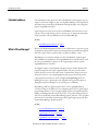
PhaseManager is a collection of features that integrates the FactoryTalk® Batch
software with the Studio 5000 Logix Designer™ application and the Logix5000™
family of controllers. The integration of these products simplifies the
configuration and maintenance of the FactoryTalk Batch automation system,
provides a superior means of communication between the FactoryTalk Batch
Server and the Logix5000 controller, and significantly reduces the programming
effort required to develop the phase logic code that resides in the Logix5000
controller.
See also
Software requirements on page 8
Intended audience on page 9
What is PhaseManager? on page 9
How PhaseManager works in a FactoryTalk Batch system on page 11
Benefits of using PhaseManager and CIP instead of OPC on page 15
Rockwell Automation Publication BATCHX-UM011D-EN-P - February 2017
7
Chapter 1
PhaseManager introduction
Software requirements
The PhaseManager features require these versions of software:
•
FactoryTalk Batch, version 13.0
•
Logix Designer, version 29
•
Logix Designer, redundancy support, versions 8, 11, 13, 15, 16, 19, 20,
and 24
•
RSLinx Classic version 3.81
•
Software Platform\Hardware Compatibility Matrix: For the latest
compatibility information for the Rockwell Automation software suite of
products, consult Rockwell Automation Product Compatibility and
Download Center.
•
Operating System:
•
•
Microsoft® Windows™ Server:
•
Microsoft Windows Server 2008 R2 Service Pack 1, Standard or
Enterprise (64-bit)
•
Microsoft Windows Server 2012 Standard Edition or DataCenter
(64-bit)
•
Microsoft Windows Server 2012 R2 Standard Edition or
DataCenter (64-bit)
Microsoft Windows operating system
•
Windows 7 Service Pack 1 Professional or Enterprise (32-bit and
64-bit)
•
Windows 8.1 Professional or Enterprise (32-bit and 64-bit)
•
Windows 10 Professional or Enterprise on version 1607 (64-bit)
(Batch Clients only)
See also
PhaseManager introduction on page 7
8
Rockwell Automation Publication BATCHX-UM011D-EN-P - February 2017
PhaseManager introduction
Intended audience
Chapter 1
The information in this guide is for FactoryTalk Batch system designers, process
engineers, and control engineers who are using PhaseManager to develop a batch
automation system with FactoryTalk Batch and Logix Designer to develop phase
logic for Logix5000 controllers.
Logix Designer users who do not use FactoryTalk Batch and only want to create
sequence routines and develop code for a specific piece of equipment that may be
incorporated into a FactoryTalk Batch system use PhaseManager.
See also
PhaseManager introduction on page 7
What is PhaseManager?
In FactoryTalk Batch Equipment Editor, create a phase class to represent a group
of equipment that performs a minor processing activity in a manufacturing plant,
and create a phase when a specific instance of a phase is added to a unit.
PhaseManager is a collection of features in FactoryTalk Batch, Logix Designer,
and an addition of capabilities in the Logix5000 family of controllers that extend
the concept and definition of phases to the Logix Designer software and the
Logix5000 family of controllers.
An equipment phase is a special kind of program. A state machine built into the
program manages the state of the equipment phase. The state specifies which
routine the phase executes. The phase can be commanded to change states, and
change the routine it is executing. Equipment phase programs have input and
output parameters. Parameters can be configured as Sequencing parameters,
marking these tags as requiring data to be supplied from an internal sequencer
(Equipment Sequence Manager) or external sequencer (FTBatch).
PhaseManager adds an equipment phase object to the Logix5000 family of
controllers and gives the ability to create equipment phases in the Logix Designer
programming software. Create or update equipment phases in Logix Designer by
adding or modifying them directly in the project, or by synchronizing the project
with an area model that contains PhaseManager phases. Likewise, create or update
phases in the area model by synchronizing with a Logix Designer project file that
contains PhaseManager equipment phases.
See also
FactoryTalk Batch features on page 10
Logix Designer features on page 10
Logix5000 Controller features on page 11
Rockwell Automation Publication BATCHX-UM011D-EN-P - February 2017
9
Chapter 1
PhaseManager introduction
FactoryTalk Batch features
PhaseManager adds these features to the FactoryTalk Batch software:
•
Common Industrial Protocol (CIP) support
The FactoryTalk Batch Server can sequence equipment phases in
Logix5000 controllers using the industry standard CIP (Common
Industrial Protocol). In FactoryTalk Batch Equipment Editor, add a
Logix5000 CIP data server for each Logix controller that contains
PhaseManager equipment phases.
•
Equipment phase synchronization
Synchronize the area model in FactoryTalk Batch Equipment Editor with
the project file in Logix Designer. Create or update an equipment phase
once in either application and add or update it to the other application by
synchronizing the FactoryTalk Batch area model with its corresponding
Logix Designer project file.
•
Navigation from FactoryTalk Batch Equipment Editor to phase logic in
a Logix Designer project
Directly navigate from a phase in FactoryTalk Batch Equipment Editor to
corresponding phase logic in the Logix Designer project file.
See also
What is PhaseManager? on page 9
Logix Designer features
PhaseManager adds these features to the Logix Designer programming software:
•
Equipment phase as a type of program
Add equipment phases to Logix Designer projects.
•
PHASE data type
Use the PHASE data type to link equipment phases to higher-level systems.
•
Special instructions for equipment phases
Use instructions in phase logic provided specifically for interacting with the
FactoryTalk Batch Server and sequencing a PhaseManager equipment
phase.
See also
What is PhaseManager? on page 9
Logix5000 Controller features on page 11
10
Rockwell Automation Publication BATCHX-UM011D-EN-P - February 2017
PhaseManager introduction
Logix5000 Controller features
Chapter 1
PhaseManager adds these features to the Logix5000 family of controllers:
•
Equipment phase objects
Equipment phase objects in the Logix5000 family of controllers
communicate with the FactoryTalk Batch Server through direct Common
Industrial Protocol (CIP) messaging. The equipment phase objects embed
the Phase Logic Interface (PLI) capabilities into all Logix5000 controllers,
eliminating the need for separate PLI code in the project.
•
Equipment Phase State Model
Modularize and organize equipment phase logic by developing the code for
each S88 state in a routine. Using this programming structure provides
consistency of implementation throughout the project.
See also
What is PhaseManager? on page 9
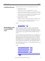
How PhaseManager works
in a FactoryTalk Batch
system
PhaseManager features work together to provide a seamless workflow that
improves the designing, troubleshooting, and commissioning phases of the
development life cycle. This discussion includes some background information
about the components of FactoryTalk Batch systems and how FactoryTalk Batch
terminology and concepts are implemented in FactoryTalk Batch and Logix
Designer.
In a FactoryTalk Batch system using PhaseManager, the FactoryTalk Batch Server
provides batch control, including recipe execution, allocation and arbitration of
equipment, binding of resources, and generation of journals. Use FactoryTalk
Batch Equipment Editor and FactoryTalk Batch Recipe Editor to configure the
FactoryTalk Batch system. Use Logix Designer to program the phase logic code
that defines the behavior of equipment phase states, including Running, Stopping,
Aborting, Holding, Restarting, and Resetting. PhaseManager links a phase in
FactoryTalk Batch Equipment Editor to a corresponding equipment phase and its
phase logic in Logix Designer.
See also
Common Industrial Protocol (CIP) on page 12
Equipment phases in Logix Designer on page 13
Equipment phase synchronization on page 14
Integration of FactoryTalk Batch Equipment Editor with Logix Designer
on page 15
Rockwell Automation Publication BATCHX-UM011D-EN-P - February 2017
11
Chapter 1
PhaseManager introduction
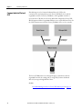
Common Industrial Protocol
(CIP)
PhaseManager uses the Common Industrial Protocol (CIP) as the
communication mechanism between the FactoryTalk Batch Server and the
Logix5000 controller. In FactoryTalk Batch, each Logix5000 controller is
represented as a CIP data server that was added and configured in FactoryTalk
Batch Equipment Editor. Logix5000 CIP data servers require RSLinx Classic for
the CIP communications from the FactoryTalk Batch Server to the controller.
The FactoryTalk Batch Server and Logix Designer communicate with the
Logix5000 controller by sending and receiving CIP (Common Industrial
Protocol) messages through RSLinx Classic.
See also
How PhaseManager works in a FactoryTalk Batch system on page 11
12
Rockwell Automation Publication BATCHX-UM011D-EN-P - February 2017
PhaseManager introduction
Equipment phases in Logix
Designer
Chapter 1
FactoryTalk Batch Equipment Editor provides the ability to create a model of the
equipment in a manufacturing plant. The phases defined in FactoryTalk Batch
Equipment Editor define the capabilities of a piece of equipment, or what the
equipment can do. When adding an instance of a phase class to a specific unit,
create a phase. Each phase represents a unique piece of equipment that can
perform the processing activity described by the phase.
Using Logix Designer with PhaseManager, can also create equipment phases in
Logix Designer controllers. An equipment phase in Logix Designer is a type of
program that represents both the specific piece of equipment and its capabilities,
or the processing activity it performs. The Logix Designer equipment phase is a
combination of the FactoryTalk Batch phase and the phase it was created from.
PhaseManager adds special Relay Ladder Logic (RLL) and Structured Text
instructions to Logix Designer used when developing phase logic to interact with
the FactoryTalk Batch Server, and for internally manipulating the equipment
phase objects in the Logix5000 controller.
See also
Equipment phase synchronization on page 14
How PhaseManager works in a FactoryTalk Batch system on page 11
Integration of FactoryTalk Batch Equipment Editor with Logix Designer
on page 15
Rockwell Automation Publication BATCHX-UM011D-EN-P - February 2017
13
Chapter 1
PhaseManager introduction
Equipment phase
synchronization
With PhaseManager, create a phase in FactoryTalk Batch Equipment Editor or
edit the definition of equipment phases, including parameters and reports, in
either FactoryTalk Batch Equipment Editor or in Logix Designer and synchronize
them in FactoryTalk Batch Equipment Editor. FactoryTalk Batch Equipment
Editor contains the tools to view synchronization status and manage the
synchronization process.
Tip:
These types of phases must be initially created and edited in FactoryTalk Batch
Equipment Editor and added to Logix Designer through the synchronization
process:
• Material phases
• Phases that contain control strategies
• Phases that contain parameter deviations
See also
Integration of FactoryTalk Batch Equipment Editor with Logix Designer
on page 15
14
Rockwell Automation Publication BATCHX-UM011D-EN-P - February 2017
PhaseManager introduction
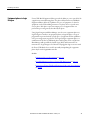
Integration of FactoryTalk
Batch Equipment Editor with
Logix Designer
Chapter 1
PhaseManager adds the ability to double-click a phase in FactoryTalk Batch
Equipment Editor and open its corresponding equipment phase in Logix Designer
to view and edit its phase logic.
Place the pointer over a phase that is assigned a CIP data server, the pointer
changes to the Logix Designer equipment phase symbol, indicating to double-click
to open Logix Designer.
See also
How PhaseManager works in a FactoryTalk Batch system on page 11
Benefits of using
PhaseManager and CIP
instead of OPC
PhaseManager improves existing functionality, and how using PhaseManager and
the Common Industrial Protocol (CIP) differs from using FactoryTalk Batch
with the OPC communication protocol.
See also
Reduced phase logic programming on page 16
Eliminates duplicate equipment phase and tag configuration on page 17
Compatible tag data types on page 18
Open phase logic in Logix Designer from FactoryTalk Batch Equipment
Editor on page 19
Improved implementation of phase logic routines on page 19
Rockwell Automation Publication BATCHX-UM011D-EN-P - February 2017
15
Chapter 1
PhaseManager introduction
Reduced phase logic
programming
Without PhaseManager, a control engineer must implement the Phase Logic
Interface (PLI), which is a set of ladder logic (RLL) routines that provides the
controller interface to the FactoryTalk Batch Server and executes the command
handshake protocol required by the server to communicate with the controller.
This communication protocol is implemented using OPC and communication
tags or other memory locations in the controller to hold commands, requests, and
other data needed by the PLI. When OPC is used, the FactoryTalk Batch Server is
compatible with any type of controller, including Logix5000 controllers, PLC-5s,
or controllers manufactured by any vendor.
In Logix Designer with PhaseManager, the functionality associated with the PLI is
embedded into the Logix5000 controller by means of equipment phase objects
and instructions. Since PhaseManager implements the PLI functionality in the
Logix5000 controller, do not implement PLI routines when using PhaseManager
to create and maintain equipment phases in the FactoryTalk Batch system.
With PhaseManager, the FactoryTalk Batch Server communicates with the
Logix5000 controller through direct CIP (Common Industrial Protocol)
messaging targeted at the new objects in the Logix5000 controller. CIP messaging
provides a faster and more reliable communication mechanism, a preferred
connectivity path, and increased throughput. The combination of embedding the
PLI functionality in the Logix5000 controller and using CIP messaging for
communication provides a seamless integration between FactoryTalk Batch,
RSLogix5000, and the Logix5000 family of controllers.
All commands previously supported from the FactoryTalk Batch Server to the
controller, such as sending a parameter value to the controller, are also supported
by PhaseManager. Likewise, all requests from the controller to the FactoryTalk
Batch Server, such as the controller requesting a new parameter value, are also
supported by PhaseManager. How these commands are sent is different when
PhaseManager is used, due to the use of CIP messaging.
See also
Data from FactoryTalk Batch Server on page 65
16
Rockwell Automation Publication BATCHX-UM011D-EN-P - February 2017
PhaseManager introduction
Chapter 1
Eliminates duplicate equipment
phase and tag configuration
In a FactoryTalk Batch system using the OPC communication protocol and the
Logix Designer programming software, manually enter communication tag data
for each of the ten standard tags and for each parameter, report, and additional
request tag on each phase in FactoryTalk Batch Equipment Editor. In Logix
Designer, manually create the corresponding tags. Each Tag Name entered in
Logix Designer must match the Tag Item Name entered in FactoryTalk Batch
Equipment Editor. Additionally, in Logix Designer manually create the tags
required for the PLI and FactoryTalk Batch Server communications.
In a FactoryTalk Batch system using Logix Designer with PhaseManager, the
FactoryTalk Batch Server communicates directly to the equipment phase objects
in the Logix5000 controller; therefore, it is not necessary to enter any
communication tag data in either application. In FactoryTalk Batch Equipment
Editor, tag names that match the parameters and reports defined on the phase are
automatically created for each phase.
Through synchronization, these tag names from the phase are automatically
created on the corresponding equipment phases in Logix Designer.
With PhaseManager, create or modify phases in FactoryTalk Batch Equipment
Editor or equipment phases in Logix Designer, and synchronize the FactoryTalk
Batch area model with the Logix Designer project file. When synchronizing the
area model with the project file, data types and tags automatically create for each
equipment phase and for all parameters and reports in Logix Designer. It is not
necessary to enter this information twice, in FactoryTalk Batch and in Logix
Designer, as is required if OPC data servers are used with FactoryTalk Batch.
Any new equipment phases added in Logix Designer, or modifications to existing
equipment phases in Logix Designer, can also be transferred to the FactoryTalk
Batch area model when the FactoryTalk Batch phases are synchronized with the
Logix Designer project.
See also
Logix Designer equipment phases in the area model on page 53
Rockwell Automation Publication BATCHX-UM011D-EN-P - February 2017
17
Chapter 1
PhaseManager introduction
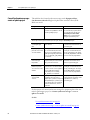
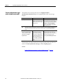
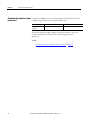
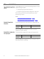
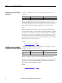
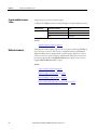
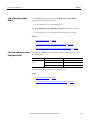
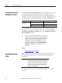
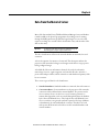
Compatible tag data types
The data types of the input and output parameter tags defined in Logix Designer
must be compatible with the data types supported in FactoryTalk Batch
Equipment Editor. These data types are supported:
Logix Designer Data Type
Corresponding FactoryTalk Batch Equipment Editor Data Types
Real
Real
DINT, INT, SINT
Integer
DINT, INT, SINT
Enumeration
String
String
See also
Open phase logic in Logix Designer from FactoryTalk Batch Equipment
Editor on page 19
Improved implementation of phase logic routines on page 19
18
Rockwell Automation Publication BATCHX-UM011D-EN-P - February 2017
PhaseManager introduction
Open phase logic in Logix
Designer from FactoryTalk
Batch Equipment Editor
Chapter 1
PhaseManager gives the ability to double-click a phase in FactoryTalk Batch
Equipment Editor and directly view and edit its phase logic in Logix Designer.
Logix Designer opens to the equipment phase in the project file that corresponds
to the phase selected in FactoryTalk Batch Equipment Editor. It is not necessary
to manually open Logix Designer and navigate to the equipment phase to view or
edit the phase logic for a phase in FactoryTalk Batch.
•
If the phase has a corresponding equipment phase in Logix Designer with
existing phase logic, Logix Designer opens the project file to the Running
routine of the equipment phase.
•
If the phase has a corresponding equipment phase in Logix Designer, and
the phase logic has not been developed yet, Logix Designer opens the project
file to the equipment phase.
•
If the phase does not have a corresponding equipment phase in Logix
Designer, Logix Designer opens the project file for the CIP data server that
is assigned to the phase.
Tip:
To open the Logix Designer project file from FactoryTalk Batch Equipment Editor,
the correct revision of Logix Designer must be installed on the same computer as
FactoryTalk Batch Equipment Editor with an activation for each product.
The PhaseManager activation is included in the Logix Designer Professional
Version, but other versions of Logix Designer require a separate PhaseManager
activation to enable the PhaseManager features in Logix Designer.
See also
Improved implementation of phase logic routines on page 19
Improved implementation of
phase logic routines
Logix Designer with PhaseManager improves the implementation of equipment
phases in Logix5000 controllers. Using OPC and the PLI, a phase is typically
executed in a single relay ladder logic (RLL) routine that implements logic for all
of the active states defined by the S88 standard. These active states include
Stopping, Starting, Running, Holding, Aborting, and Restarting.
Tip:
PhaseManager also provides an additional active state in Logix Designer,
Resetting, that can be used for other types of projects not based on the S88
standard.
PhaseManager supports a modularized approach to developing state routine logic
by facilitating the development of each active state in its own routine.
PhaseManager represents an equipment phase as a type of program in Logix
Designer. Since programs can contain multiple routines, develop a separate
routine for each active state required for the equipment phase. Developing
separate routines for each active state also provides the ability to develop each
routine in different programming languages.
Rockwell Automation Publication BATCHX-UM011D-EN-P - February 2017
19
Chapter 1
PhaseManager introduction
Use other Logix Designer program features when developing equipment phase
logic. These features include the ability to use timing diagnostics information, Max
and Last Scan, for debugging equipment phases in Logix Designer, and the ability
to configure a fault routine for the equipment phase.
See also
Benefits of using PhaseManager and CIP instead of OPC on page 15
Additional resources
These documents contain additional information concerning related Rockwell
Automation products.
Resource
Description
FactoryTalk Batch Equipment Editor User Guide
The FactoryTalk Batch Equipment Editor is a graphical
interface used to create and maintain an equipment
database. This process equipment database is called an
area model. The area model is stored in a file with a .cfg
file extension and is available to all other FactoryTalk
Batch programs, including the Recipe Editor, View, and
Phase Simulator.
Logix Designer online help.
The Logix Designer application provides one
programming software for sequential, process, drive, and
motion control programming that is compliant with the
EC61131-3 standard. The Logix Designer application
supports symbolic programming with structures and
arrays, and an instruction set that serves many types of
applications in an environment that is common to the
Rockwell Automation® Logix platforms: ControlLogix and
CompactLogix.
The Logix Designer application is designed to work with
Rockwell Automation Logix Platforms and the
Logix5000™ family of controllers.
Logix5000 Controllers PhaseManager User Manual
Provides set up and program information for a Logix5000
controller to use Equipment Phases. It gives guidance and
examples to:
• Lay-out code in sections that include Equipment
Phases.
• Set up a state model for equipment.
• Program equipment to run by the state model.
Use Equipment Phase instructions to transition to a
different state, handle faults, set up break points, and so
forth.
FactoryTalk Batch PCD Programmer Technical Reference
Guide
Provides information and instructions about the
FactoryTalk® Batch-PCD interface design. It is intended to
be used as a reference guide.
View or download publications at
http://www.rockwellautomation.com/literature . To order paper copies of
technical documentation, contact the local Rockwell Automation distributor or
sales representative.
20
Rockwell Automation Publication BATCHX-UM011D-EN-P - February 2017
Chapter 2
Area model PhaseManager configuration
Use FactoryTalk Batch with PhaseManager to configure the area model in
FactoryTalk Batch Equipment Editor, or develop the phase logic in Logix
Designer. If designing an entire FactoryTalk Batch system, use FactoryTalk Batch
Equipment Editor to create an area model that describes the capabilities of the
equipment, down to the phase level, and use the synchronization feature to create
corresponding equipment phases in the Logix Designer project file.
This section describes how to configure data servers and phases in FactoryTalk
Batch Equipment Editor so these PhaseManager features can be used:
•
CIP for FactoryTalk Batch Server communications to the Logix5000
controller
•
Synchronization of phases in the FactoryTalk Batch area model with the
Logix Designer project file
•
Ability to open phase logic in Logix Designer from the phase in FactoryTalk
Batch Equipment Editor
Tip:
To fully use the PhaseManager features, install FactoryTalk Batch Equipment Editor
and Logix Designer on the same computer.
To configure the FactoryTalk Batch system with PhaseManager:
•
Add Logix5000 CIP data servers
•
Assign a Logix5000 CIP data server to PhaseManager phases
After these configuration tasks are completed, automatically create the
FactoryTalk Batch phases in the Logix Designer project file by synchronizing the
area model with the project file.
See also
FactoryTalk Batch phases in Logix Designer on page 35
Add a Logix5000 CIP data server on page 22
Edit a Logix5000 CIP data server on page 31
Assign a Logix5000 CIP data server to a phase on page 32
Rockwell Automation Publication BATCHX-UM011D-EN-P - February 2017
21
Chapter 2
Area model PhaseManager configuration
Add a Logix5000 CIP data
server
Add data servers either before creating the rest of the elements in the area model,
or after the process cells, unit classes, phase classes, and resources in the area model
are defined. Define at least one data server before creating the specific phases from
the phase classes.
If possible, create the project file in Logix Designer before adding a Logix5000 CIP
data server. Specify the project file when a Logix5000 CIP data server is added to
detect errors more easily when designing the system.
To add a Logix5000 CIP data server:
1. Specify the Data Server Name and Type.
2. Select a project file.
3. Select the controller network path.
4. (optional) Optimize the timing of server communication to the controller.
See also
Specify the data server name and type on page 23
Select a project file on page 25
Select a project file - error messages on page 27
Select the controller network path on page 28
Optimize the timing of the server communication connection to the
controller on page 30
22
Rockwell Automation Publication BATCHX-UM011D-EN-P - February 2017
Area model PhaseManager configuration
Specify the data server name
and type
Chapter 2
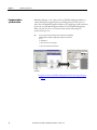
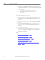
To add data servers, give each one a name and specify the type of data server. Add
one data server for each Logix5000 controller in the system. When creating
phases, assign a data server to each one.
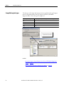
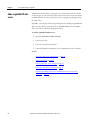
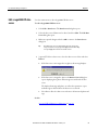
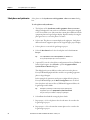
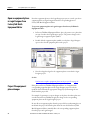
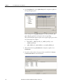
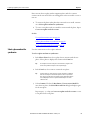
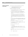
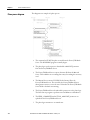
To specify the data server name and type:
1. Open FactoryTalk Batch Equipment Editor.
2. Select Edit > Data Server. The Data Servers dialog box opens.
3. Select the Add... button. The Add Data Server dialog box opens.
Rockwell Automation Publication BATCHX-UM011D-EN-P - February 2017
23
Chapter 2
Area model PhaseManager configuration
4. In Name, enter a name for the data server. This name should easily identify
the Logix5000 controller that this data server represents. A suggested name
is the type of Logix5000 controller and its location in the chassis, or the
phase/ unit that this controller is connected to in the plant.
Tip:
When ready to synchronize the area model with the Logix Designer project, this
name displays in the Synchronize Logix5000 Data Servers dialog box. Choose
which data server to synchronize by selecting its name.
5. From the Type list, select Logix5000 CIP.
Now that a data server is added, there are several ways to proceed:
•
To create phases in the area model, select OK to close this dialog box. Finish
adding information about the data server later.
•
If the Logix Designer project file associated with this data server is known,
continue to Select a project file.
•
If the project file associated with this data server is not known, the
controller to be used is known, see Select the controller network path.
See also
Select a project file on page 25
Select the controller network path on page 28
Optimize the timing of the server communication connection to the
controller on page 30
24
Rockwell Automation Publication BATCHX-UM011D-EN-P - February 2017
Area model PhaseManager configuration
Select a project file
Chapter 2
After a name for Logix5000 CIP data server is specified, select the Logix Designer
project file that contains the phase logic for the controller this data server
represents.
Select a project file for a data server the Logix Designer project is synchronized.
Specify a project file and synchronize the area model with the Logix Designer
project to allow full use of the PhaseManager features to easily detect errors while
designing the FactoryTalk Batch system.
Important:
To select a project file, install Logix Designer on the same computer as
FactoryTalk Batch Equipment Editor.
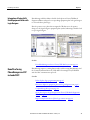
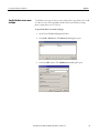
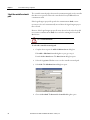
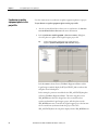
To select a project file:
1. Complete these steps in the Add or Edit Data Server dialog box.
If the Add or Edit Data Server dialog box is open, go to step 5.
Select Edit > Data Server. The Data Servers dialog box opens.
2. Select the Logix5000 CIP data server to specify a project file.
3. Select Edit. The Edit Data Server dialog box opens.
4. Select Browse. The Select Project File dialog box opens.
5. Navigate to the Logix Designer project (.acd file) that contains the phase
logic for the controller this data server represents. Select it and select Open.
Tip:
The Logix Designer project file must be revision 16.0 or higher.
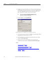
The Edit Data Server dialog box displays the Path of the project file
selected, the Revision of the project file, and the Controller Type that the
project file specifies.
The Controller Network Path also displays the communications path that
is specified in the Path box of the Logix Designer project.
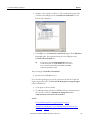
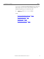
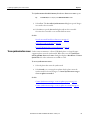
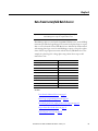
6. If no Path is specified in the Logix Designer project, this message displays:
Rockwell Automation Publication BATCHX-UM011D-EN-P - February 2017
25
Chapter 2
Area model PhaseManager configuration
7. Select OK. The Controller Network Path box displays <unknown>. Select
a Controller Network Path later. (See Select the controller network path
for more information.)
Tip:
If any other error messages are encountered when a project file is selected, see
Select a project file - error messages for a list of possible error messages and
how to resolve them.
Now the Logix Designer project file is selected:
•
Synchronize this data server with the Logix Designer project file selected.
(See Synchronize to create equipment phases in the project file for more
information.)
•
Run the FactoryTalk Batch Server, only if the Controller Network Path is
specified.
•
Select a Controller Network Path if one was not specified in the Logix
Designer project file. (See Select the controller network path for more
information.)
•
Create phases in the area model.
•
To adjust the timing of the FactoryTalk Batch Server communications to
the controller, see Optimize the timing of the server communication
connection to the controller.
See also
Select the controller network path on page 28
Select a project file - error messages on page 27
Synchronize area model with project file on page 36
Select the controller network path on page 28
Optimize the timing of the server communication connection to the
controller on page 30
26
Rockwell Automation Publication BATCHX-UM011D-EN-P - February 2017
Area model PhaseManager configuration
Select a project file - error messages
Chapter 2
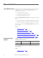
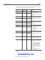
If error messages display when a Logix Designer project file is selected, use this
table to troubleshoot.
Error Message
Action to Take
The specified Logix Designer project
file was not found.
The file could have been renamed, moved, or deleted after it was selected in the
Select Project File dialog box.
In Windows Explorer, navigate to the file selected in the Select Project File dialog
box, and verify that it still exists with the same name in the selected location.
No revision of Logix Designer is
installed.
Logix Designer is not installed on the same computer as FactoryTalk Batch
Equipment Editor.
Install Logix Designer revision 16.0 or higher on the same computer as FactoryTalk
Batch Equipment Editor.
The revision of Logix Designer
required to open the project is not
installed.
The installed revision of Logix Designer does not support PhaseManager
functionality.
Upgrade the current installation of Logix Designer to revision 16.0 or higher.
The Logix Designer project file must
be converted. The revision is too old.
The revision of the selected Logix Designer project file is lower than revision 16.0.
Open the selected project file in Logix Designer revision 16.0 or higher, to convert
the file to this revision.
The specified file is not a valid Logix Try to open the selected project file in Logix Designer. If it does not open, the file
Designer project file. The file format is format has been corrupted.
not recognized or has been corrupted.
RSLinx is not installed. The Controller Install RSLinx Classic, version 3.8.
Network Path could not be verified.
The Logix Designer project file is
read-only and cannot be opened.
Disable the Read-Only Attribute for the selected project file. In Windows Explorer,
navigate to the selected file in the Select Project File dialog box. Open the
Properties dialog box for the file and verify that the Read-Only Attribute is not
selected.
The Controller Network Path is not set Set the Path for the project file in Logix Designer and save the .ACD file in Logix
in the Logix Designer project file. The Designer. Select the project file again in FactoryTalk Batch Equipment Editor.
Controller Network Path could not be OR
verified.
Manually select the Path in FactoryTalk Batch Equipment Editor. (See Select the
controller network path for more information.)
The Controller Network Path set in
the Logix Designer project file could
not be verified. Confirm that RSLinx is
configured appropriately for this
Controller Network Path.
The driver specified in the Path in the Logix Designer project must also be
configured in RSLinx.
In the Project file, modify the Path to include a driver that is configured in RSLinx.
Or in RSLinx, configure a driver to match the driver specified in the project file Path.
The Logix Designer project file
The installed revision of Logix Designer and the revision of the selected project file is
revision does not support phases. Use lower than revision 16.0.
revision 16.0 or greater.
Upgrade the revision of Logix Designer to 16.0 or higher. Open the selected project
file in Logix Designer, to convert the file to the upgraded revision.
See also
Select the controller network path on page 28
Rockwell Automation Publication BATCHX-UM011D-EN-P - February 2017
27
Chapter 2
Area model PhaseManager configuration
Select the controller network
path
The controller network path is the network communication path to the controller
this data server represents. This is the controller the FactoryTalk Batch Server
communicates with.
If the Logix Designer project file specifies the communications Path, it is not
necessary to select it. It is automatically entered when the Logix Designer project
file is selected.
However, if the Logix Designer project file is not selected, or the selected one did
not contain a communications Path, select one before running the FactoryTalk
Batch Server.
Install RSLinx Classic must on the same computer as FactoryTalk Batch Equipment Editor
to select a Controller Network Path.
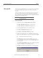
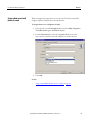
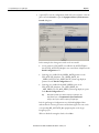
To select the controller network path:
1. Complete these steps in the Add or Edit Data Server dialog box.
If the Add or Edit Data Server dialog box is open, go to step 5.
From the Edit > Data Server. The Data Servers dialog box opens.
2. Select the Logix5000 CIP data server to set the controller network path.
3. Select Edit. The Edit Data Server dialog box opens.
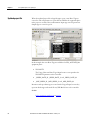
4. Choose Select Path. The Browse for Controller dialog box opens.
28
Rockwell Automation Publication BATCHX-UM011D-EN-P - February 2017
Area model PhaseManager configuration
Chapter 2
5. Navigate to the controller, and select it. The communications path of the
controller selected displays in the Controller Network Path box at the
bottom of the dialog box.
6. Select OK to close the Browse for Controller dialog box. In the Edit Data
Server dialog box, the communications path selected displays in the
Controller Network Path box.
Tip:
An asterisk (*) at the end of the Controller Network Path indicates that the
controller network path was set using Select Path instead of browse. If there is
an *, the controller network path displayed may be different from the Path
specified in the Logix Designer project file.
After selecting the Controller Network Path:
•
Run the FactoryTalk Batch Server.
For a selected Logix Designer project file, synchronize the data server with the
Logix Designer project file. (See FactoryTalk Batch phases in Logix Designer
for more information).
•
Create phases in the area model.
•
To adjust the timing of the FactoryTalk Batch Server communications to
the controller, continue to Optimize the timing of the server
communication connection to the controller.
See also
FactoryTalk Batch phases in Logix Designer on page 35
Optimize the timing of the server communication connection to the
controller on page 30
Rockwell Automation Publication BATCHX-UM011D-EN-P - February 2017
29
Chapter 2
Area model PhaseManager configuration
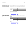
Optimize the timing of the
server communication
connection to the controller
Use these instructions to optimize the timing of the server communication
connection to the controller.
To optimize the timing of the server communication connection to the
controller:
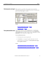
1. Select Edit > Data Server. The Data Servers dialog box opens.
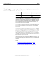
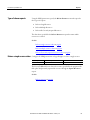
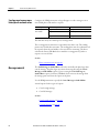
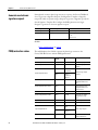
2. Select More to display the Timeout and Retries box.
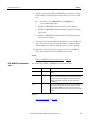
3. The default values are the recommended settings for these boxes. However,
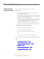
adjust these values for the speed of the network.
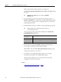
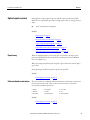
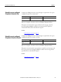
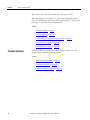
Name
Value
Timeout
How often the FactoryTalk Batch Server attempts to contact the controller. The range
of valid values is 500 to 100000 milliseconds. The default is 8000.
Retries
The number of times the FactoryTalk Batch Server tries to contact the controller before
dropping the connection. The valid values appear in the list. The default is 4.
Timeout * Retries = Length of time the FactoryTalk Batch Server attempts to contact the controller before losing the
connection.
See also
Add a Logix5000 CIP data server on page 22
30
Rockwell Automation Publication BATCHX-UM011D-EN-P - February 2017
Area model PhaseManager configuration
Edit a Logix5000 CIP data
server
Chapter 2
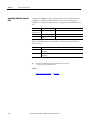
Use these instructions to edit a Logix5000 CIP data server.
To edit a Logix5000 CIP data server:
1. Select Edit > Data Server. The Data Servers dialog box opens.
2. Select the data server definition to be edited, and select Edit. The Edit Data
Server dialog box opens.
3. Make any required changes and select OK to return to the Data Servers
dialog box.
Tip:
After adding a data server as a Logix5000 CIP type data server, the type cannot
change. No other data server types appear in the Type selection list when editing.
To change the Type, delete the data server and add a new one.
4. (optional) To delete a data server, select the data server to delete and select
Remove.
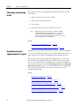
•
If the data server is not assigned to any phases, this message displays:
•
If the data server is assigned to phases, the Remove Server dialog box
opens, displaying these phases and unit tags associated with the data
server.
The displayed unit tags and phases, as well as their parameter, report,
and limit tags are deleted when the data server is removed.
•
Select Yes to delete the data server and remove all associated phases and
tags.
See also
Area model PhaseManager configuration on page 21
Rockwell Automation Publication BATCHX-UM011D-EN-P - February 2017
31
Chapter 2
Area model PhaseManager configuration
Assign a Logix5000 CIP data
server to a phase
After adding a Logix5000 CIP data server, assign it to each phase that represents a
piece of equipment connected to the controller specified in the controller network
path of the Logix5000 CIP data server.
To assign a Logix5000 CIP data server to a phase:
1. Select the phase icon in the Design View area and select Edit > Properties.
The Edit Phase dialog box, General tab displays.
2. From the Data Server list, select the Logix5000 CIP data server that
represents the controller connected to the piece of equipment defined by
this phase.
3. Select OK.
See also
Assign a data server to all phases in a unit on page 33
32
Rockwell Automation Publication BATCHX-UM011D-EN-P - February 2017
Area model PhaseManager configuration
Assign a data server to all
phases in a unit
Chapter 2
When creating a unit, assign a data server to the unit. This data automatically
assigns to all phases subsequently created in that unit.
To assign a data server to all phases in a unit:
1. Select the unit icon in the Design View area and select Edit > Properties.
The Edit Unit dialog box, General tab displays.
2. From the Data Server list, select the Logix5000 CIP data server that
represents the controller connected to all phases created in this unit.
3. Select OK.
See also
Assign a Logix5000 CIP data server to a phase on page 32
Rockwell Automation Publication BATCHX-UM011D-EN-P - February 2017
33
Chapter 3
FactoryTalk Batch phases in Logix Designer
After the Logix5000 data servers are added and assigned to phases, create the same
phases in the Logix Designer programming software by synchronizing the area
model with the Logix Designer project file.
This section describes how to synchronize the FactoryTalk Batch area model with
the Logix Designer project file when the phases in FactoryTalk Batch Equipment
Editor are created and corresponding equipment phases in Logix Designer are
needed. Phases based on these types of phases must be initially created in
FactoryTalk Batch Equipment Editor and added to Logix Designer through the
synchronization process:
•
Material based recipe phases
•
Phases that contain control strategies
•
Phases that contain parameter deviations
The features to configure these types of complex phases are unique to the
FactoryTalk Batch product. Logix Designer does not have the configuration
features to enable material phases, control strategies, or parameter deviations. For
that reason, configure these phase classes and phases in FactoryTalk Batch first,
and then follow the instructions in this chapter to synchronize the area model
with the Logix Designer project file. When corresponding equipment phases in
Logix Designer are synchronizing, the appropriate configuration of parameters,
reports, and tags on these complex phases are automatically created on the
equipment phases in Logix Designer.
Tip:
Phases are created in Logix Designer as equipment phases.
After equipment phases are created in the Logix Designer project, begin
developing phase logic for them in Logix Designer.
See also
Synchronize the area model with the project file on page 36
Project file equipment phase changes on page 44
Rockwell Automation Publication BATCHX-UM011D-EN-P - February 2017
35
Chapter 3
FactoryTalk Batch phases in Logix Designer
Synchronize the area model
with the project file
Use these instructions to synchronize the area model with the project file.
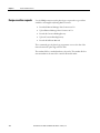
Before you begin:
•
Install Logix Designer and RSLinx Classic on the same computer as
FactoryTalk Batch Equipment Editor.
•
Create phases in FactoryTalk Batch Equipment Editor and assigned a
Logix5000 CIP data server.
•
Create a project file in Logix Designer.
•
Specify this project file in the Add or Edit Data Server dialog box for the
appropriate data server.
To synchronize the area model with the project file:
1. Save the area model and select a data server to synchronize.
2. Select the phases to create in the Logix Designer project.
3. Synchronize, review the results, and save the project.
All synchronization steps are completed in FactoryTalk Batch Equipment Editor.
See also
Save the area model and select a data server on page 37
Select phases and synchronize on page 38
Review results and save files on page 39
Results of creating equipment phases in a project by synchronizing
on page 41
36
Rockwell Automation Publication BATCHX-UM011D-EN-P - February 2017
FactoryTalk Batch phases in Logix Designer
Save the area model and select
a data server
Chapter 3
Use these steps to begin synchronizing the area model with the Logix Designer
project.
To save the area model and select a data server:
1. From the Edit menu, select Synchronize Logix5000 Data Servers. The
Save Before Synchronization dialog box opens.
2. Select Save to save the area model file now, or select Continue Without
Saving.
•
If Save is selected, the Save As dialog box opens. Save the area model
with its existing name or give it a different name.
•
After saving or continuing, the Synchronize Logix5000 Data Servers
dialog box opens.
3. Select the data server that was added for the new Logix5000 controller.
Tip:
Select any column headings to sort the list of data servers.
Important:
The data server selected must have the project file specified.
4. Select Continue. The Synchronize with Logix5000: <data server name>
dialog box opens.
5. Select the phases to create in the area model. Continue to Select phases.
See also
Select phases on page 56
Select phases and synchronize on page 38
Rockwell Automation Publication BATCHX-UM011D-EN-P - February 2017
37
Chapter 3
FactoryTalk Batch phases in Logix Designer
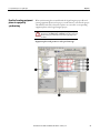
Select phases and synchronize
Select phases on the Synchronize with Logix5000: <data server name> dialog
box.
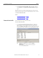
To select phases and synchronize:
1. The left pane of the Synchronize with Logix5000: <data server name>
dialog box displays the units in the area model that contain phases assigned
to the selected data server. Only units that contain phases different from the
equipment phases in Logix Designer display. Expand a unit by selecting the
plus sign next to it, to view the phases it contains.
2. Select a unit. The phases it contains display in the right pane. Only phases
different from the equipment phases in the Logix Designer project display.
3. Select a phase to create in the Logix Designer project.
4. Select the Resolution box for the selected phase and select Create in
Project.
Tip:
If the only Resolution available is Cannot Synchronize, select Details to see a
message that explains why the phase cannot be synchronized.
5. (optional) To view the selected phase configurations in FactoryTalk Batch
and in Logix Designer, select Details to open the Equipment Phase
Synchronization Details dialog box.
This dialog box shows any differences that exist between the phase in
FactoryTalk Batch Equipment Editor and the corresponding equipment
phase in Logix Designer.
In this example, the parameters and reports configured for the phase in
FactoryTalk Batch display in the Batch Configuration area on the left.
Since this phase only exists in FactoryTalk Batch Equipment Editor, the
Logix Designer side is blank.
Tip:
Although the report limit tags are defined as Input tags in Logix Designer, they
display with the reports on the Equipment Phase Synchronization Details
dialog box. Other reports are defined as Output tags in Logix Designer.
6. Select Close when finished viewing the phase details.
7. Repeat steps 3 - 5 for each phase in the selected unit to be created in the
Logix Designer project.
8. Repeat steps 2 - 6 for each unit that contains phases to be created in the
Logix Designer project.
38
Rockwell Automation Publication BATCHX-UM011D-EN-P - February 2017
FactoryTalk Batch phases in Logix Designer
Chapter 3
9. On the Synchronize with Logix5000: <data server name> dialog box,
select Synchronize. The Synchronization Results Summary dialog box
opens.
The phases selected are created in the Logix Designer project. Next review the
results of the synchronization and save the Logix Designer project file. Continue
on to Review results and save files.
See also
View synchronization issues on page 51
Review results and save files on page 39
Review results and save files
Use these instructions to review results and save files.
To review results and save files:
1. On the Synchronization Results Summary for Server: <data server
name> dialog box, review the displayed results of the synchronization.
Phases with a Result of Successful created in the Logix Designer project. If
satisfied with the results, select Yes to save the Logix Designer project file.
Tip:
If Failed displays in the Result column, the reason displays in the Additional
Information column.
If not satisfied with the results, select No. The synchronization changes displayed
are not saved in the Logix Designer project file.
Rockwell Automation Publication BATCHX-UM011D-EN-P - February 2017
39
Chapter 3
FactoryTalk Batch phases in Logix Designer
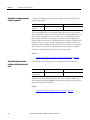
The time and status of the synchronization displays in the Synchronize
Logix5000 Data Servers window.
Status of Last
Synchronization
Description
Complete
All results were Successful, and Yes was selected to save the project file.
Incomplete
Some results were Failed or Skipped, or No was selected and did not save the
project file.
Never Synchronized
Tip:
Never been an attempt to synchronize the data server.
The Status of Last Synchronization column only displays the result of the last
synchronization attempt, if one was made. It does not indicate whether the data
server is currently synchronized. Changes may have been made since the last
synchronization attempt.
2. Select a data server and select Continue to begin the synchronization
process again, or if finished synchronizing, select Close.
When Close is selected, the Save After Synchronization dialog box opens
if changes were made to the area model.
3. Select Save to save the area model, overwrite the area model, or save it with a
different name.
After creating the equipment phases in the Logix Designer project, begin
developing phase logic for them in Logix Designer.
See also
Results of creating equipment phases in a project by synchronizing
on page 41
40
Rockwell Automation Publication BATCHX-UM011D-EN-P - February 2017
FactoryTalk Batch phases in Logix Designer
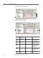
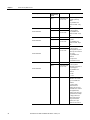
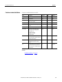
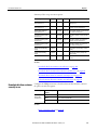
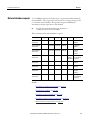
Results of creating equipment
phases in a project by
synchronizing
Chapter 3
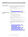
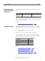
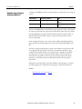
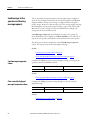
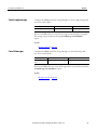
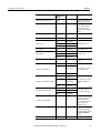
When synchronizing the area model with the Logix Designer project file and
creating equipment phases in the project, several items are created in the project.
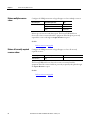
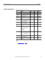
This table shows how the elements of a phase are created for a corresponding
equipment phase in the Logix Designer project:
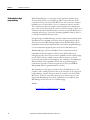
Do not edit the phase tags containing a leading underscore (_) in the Logix
Designer project. If the Name, Usage, or Data Type of these phase tags in Logix
Designer are changed, synchronization cannot be used to apply changes to the
area model.
Equipment phase with parameter and report limit tags
Rockwell Automation Publication BATCHX-UM011D-EN-P - February 2017
41
Chapter 3
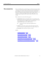
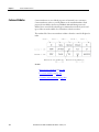
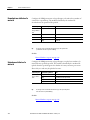
FactoryTalk Batch phases in Logix Designer
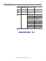
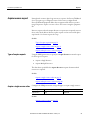
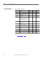
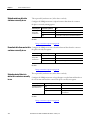
Equipment phase with control strategies
Material-enabled equipment phase
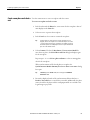
In Logix Designer Project
Notes
Phase Name
Equipment Phase Name
Created in the Unscheduled
Programs / Phases folder.
Equipment ID
Equipment ID
Displayed on Equipment Phase
Properties dialog box, General
tab.
Parameters
Phase Tags with Usage of Input Data Type matches the Type in
FactoryTalk Batch. Enumerations in
FactoryTalk Batch are created as
Integers in the project.
Reports
Phase Tags with Usage of
Output
Data Type matches the Type in
FactoryTalk Batch. Enumerations in
FactoryTalk Batch are created as
Integers in the project.
Parameter Limit Tags
Phase Tags with a Usage of
Input
An underbar ( _ ) prepends to the
tag name.
Item Number in In FactoryTalk Batch
Picture
Equipment Editor
42
Rockwell Automation Publication BATCHX-UM011D-EN-P - February 2017
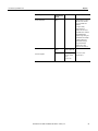
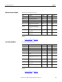
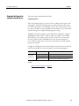
FactoryTalk Batch phases in Logix Designer
Chapter 3
In Logix Designer Project
Notes
Report Limit Tags
Phase Tags with a Usage of
Input
An underbar ( _ ) prepends to the
tag name.
Control Strategies
Phase Tag named
_CONTROL_STRATEGY with a
Usage of Input.
Data Type is DINT.
Material-based Phases
Adds these Phase Tags with a Usage of Input:
Item Number in In FactoryTalk Batch
Picture
Equipment Editor
• _MATERIAL
Data Type is DINT.
• _AMOUNT
Data Type is REAL.
Adds these Phase Tags with a Usage of Input if these optional
parameters exist on the phase in the area model:
• _CONTAINER
Data Type is DINT.
• _LOT
Data Type is STRING.
• _MATERIAL_CLASS
Data Type is DINT.
• _LABEL
Data Type is STRING.
Adds these Phase Tags with a Usage of Output:
• _ACTUAL_AMOUNT
Data Type is REAL.
• _FEED_COMPLETE
Data Type is DINT.
See also
Synchronize area model with project file on page 36
Rockwell Automation Publication BATCHX-UM011D-EN-P - February 2017
43
Chapter 3
FactoryTalk Batch phases in Logix Designer
Open an equipment phase
in Logix Designer from
FactoryTalk Batch
Equipment Editor
Now that equipment phases in the Logix Designer project are created, open those
equipment phases in Logix Designer from their corresponding phases in
FactoryTalk Batch Equipment Editor.
To open an equipment phase in Logix Designer from FactoryTalk Batch
Equipment Editor:
1. In FactoryTalk Batch Equipment Editor, place the pointer over a phase that
was just created in the Logix Designer project. The pointer changes to the
Logix Designer equipment phase symbol.
2. Double-click the equipment phase symbol over the phase. Logix Designer
opens to the selected equipment phase in the project.
3. Next, develop phase logic for the equipment phases created in the Logix
Designer project.
See also
Synchronize to update equipment phases in the project file on page 46
Project file equipment
phase changes
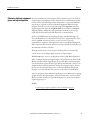
If the phases in FactoryTalk Batch Equipment Editor are changed and the
corresponding equipment phases in the Logix Designer project need to be
updated, detect and make the appropriate changes by synchronizing the area
model with the project file.
For example, if a parameter or report changes on the phase class that a phase was
created from in FactoryTalk Batch, apply the change to the corresponding
equipment phases in the Logix Designer project.
Do not delete an equipment phase from the project file by synchronizing the area
model with the project. If deleted a phase from the area model in FactoryTalk
Batch Equipment Editor, manually delete the corresponding equipment phase
from the project in Logix Designer.
44
Rockwell Automation Publication BATCHX-UM011D-EN-P - February 2017
FactoryTalk Batch phases in Logix Designer
Chapter 3
These types of changes to the phase in FactoryTalk Batch Equipment Editor can
be transferred to the corresponding equipment phase in Logix Designer through
synchronization:
•
Phase name
•
Equipment ID
•
Addition, deletion, or modification of parameters on the phase class that
the phase is associated with
•
Addition, deletion, or modification of reports on the phase that the phase is
associated with
•
Enabling, disabling, or changing the parameter or report limit tags on the
phase
•
Enabling or disabling Control Strategy or Material Based Recipe
functionality for the phase class that the phase is associated with
After changes to the area model in FactoryTalk Batch Equipment Editor are made,
transfer these changes to the equipment phases in the Logix Designer project.
See also
Delete parameters and reports on page 51
Synchronize to update equipment phases in the project file on page 46
Updated project file on page 50
Deleted parameters and reports on page 51
Rockwell Automation Publication BATCHX-UM011D-EN-P - February 2017
45
Chapter 3
FactoryTalk Batch phases in Logix Designer
Synchronize to update
equipment phases in the
project file
Use these instructions to synchronize to update equipment phases in a project:
To synchronize to update equipment phases in the project file:
1. Save the area model and select a data server to synchronize. See Save the
area model and select a data server for more information.
2. In the Synchronize with Logix5000: <data server name> dialog box,
select the phases to update in the Logix Designer project file.
Tip:
Only phases different from the equipment phases in the Logix Designer project
display in the Synchronize with Logix5000: <data server name> dialog box.
In the Location column, FactoryTalk Batch Equipment Editor and the
Logix Designer symbols display for WP_AGITATE_M2 to indicate that
this phase exists in both places.
In this example, a parameter was added to the WP_AGITATE_M2 phase
in FactoryTalk Batch Equipment Editor. This is the only phase in the
WP_MIXER2 unit that was changed since the area model was last
synchronized with the Logix Designer project. All other phases in the
WP_MIXER2 unit were created in the Logix Designer project the last time
the area model was synchronized with the project. Therefore,
WP_AGITATE_M2 is the only phase displayed in the WP_MIXER2 unit.
46
Rockwell Automation Publication BATCHX-UM011D-EN-P - February 2017
FactoryTalk Batch phases in Logix Designer
Chapter 3
3. (optional) To view the configuration details of the selected phase, select the
phase and select Details to open the Equipment Phase Synchronization
Details dialog box.
In this example, these changes were made to the area model:
•
A new parameter, VISCOSITY, was added to the AGITATE phase
that the WP_AGITATE_M2 phase was created from. It displays in the
Batch Configuration area.
•
Limit tags were enabled for the SPEED_RATE parameter on the
WP_AGITATE_M2 phase. The _SPEED_RATE_M,
_SPEED_RATE_H, and _SPEED_RATE_L limit tags display as
parameters in the Batch Configuration area.
•
Limit tags were enabled for the MIX_SPEED report on the
WP_AGITATE_M2 phase. The _MIX_SPEED_M,
_MIX_SPEED_H, and _MIX_SPEED_L limit tags display as reports
in the Batch Configuration area.
Tip:
Although the report limit tags are defined as Input tags in Logix Designer, they
display with the reports on the Equipment Phase Synchronization Details
dialog box. Other reports are defined as Output tags in Logix Designer.
In the Logix Designer Configuration area, the blank highlighted lines
indicate that the Viscosity parameter and the limit tags do not exist on the
corresponding WP_AGITATE_M2 equipment phase in the Logix
Designer project.
When are finished viewing the details, select Close.
Rockwell Automation Publication BATCHX-UM011D-EN-P - February 2017
47
Chapter 3
FactoryTalk Batch phases in Logix Designer
4. In the Resolution box, select Update Project for each phase to update in
the Logix Designer project.
In this example, selecting Update Project for the WP_AGITATE_M2
phase adds these parameters and reports to the corresponding
WP_AGITATE_M2 equipment phase in the Logix Designer project when
the synchronization is complete:
•
VISCOSITY, _SPEED_RATE_H, _SPEED_RATE_L, and
_SPEED_RATE_M
•
_MIX_SPEED_H, _MIX_SPEED_L, and _MIX_SPEED_M
5. When finished selecting a Resolution for each phase to update, select
Synchronize.
6. Review the results, and save the project and area model files. See Review
results and save files for more information.
48
Rockwell Automation Publication BATCHX-UM011D-EN-P - February 2017
FactoryTalk Batch phases in Logix Designer
Chapter 3
In this example, the Synchronization Results Summary for Server:<data server
name> dialog box shows the results for the WP_AGITATE_M2 phase: the
Resolution is Update Project and the Result is Successful.
Tip:
If Failed displays in the Result column, the reason displays in the Additional
Information column.
See also
Save the area model and select a data server on page 37
Review results and save files on page 39
Updated project file on page 50
Deleted parameters and reports on page 51
Rockwell Automation Publication BATCHX-UM011D-EN-P - February 2017
49
Chapter 3
FactoryTalk Batch phases in Logix Designer
Updated project file
When the updated project file in Logix Designer opens, a new Phase Tag was
creates for each new parameter or report that was added to the equipment phase
in the project as a result of the synchronization. Input tags create for parameters.
Output tags are create for reports.
In this example, these new Phase Tags were added to the WP_ AGITATE_M2
equipment phase:
•
VISCOSITY
The Usage of this new Phase Tags is Input because it corresponds to the
VISCOSITY parameter in the area model.
•
_SPEED_RATE_H, _SPEED_RATE_L, and _SPEED_RATE_M
•
_MIX_SPEED_H, _MIX_SPEED_L, and _MIX_SPEED_M
Parameter and report limit tags are created with a Usage of Input, because they
represent data being sent from the FactoryTalk Batch Server to the controller.
See also
Delete parameters and reports on page 51
50
Rockwell Automation Publication BATCHX-UM011D-EN-P - February 2017
FactoryTalk Batch phases in Logix Designer
Chapter 3
Deleted parameters and reports
When a parameter or report deletes from a phase in the area model and
synchronizes to update the project, the Phase Tag remains in the Logix Designer
project, but the Usage changes to <normal>.
See also
Project file equipment phase changes on page 44
Updated project file on page 50
View synchronization issues
Under certain circumstances, a FactoryTalk Batch phase or a Logix Designer
equipment phase cannot be synchronized. When this occurs, the Synchronize
with Logix5000:<data server name> dialog box displays a Resolution of Cannot
Synchronize. No other resolutions are available to select.
To view synchronization issues:
1. Select the phase that cannot be synchronized.
2. Select Details to see a message that explains why the phase cannot be
synchronized. For a list of messages, see Cannot Synchronize messages create or update area model.
See also
Cannot Synchronize messages - create or update project on page 52
Cannot synchronize messages - create or update area model on page 64
Rockwell Automation Publication BATCHX-UM011D-EN-P - February 2017
51
Chapter 3
FactoryTalk Batch phases in Logix Designer
Cannot Synchronize messages create or update project
This table lists the Cannot Synchronize messages in the Equipment Phase
Synchronization Details dialog box for phases that exist in the FactoryTalk
Batch area model:
Message
Description
How To Resolve
Duplicate phase name.
A phase with the same name was manually
created in the FactoryTalk Batch area model
and in the Logix Designer project.
Delete the phase from one location, either
the area model or the project file, and then
try synchronizing again. This time select
Create in Project or Create in Area
Model to create a corresponding phase
through the synchronization process.
Tip: If the phase is based on a phase that contains control strategies, parameter deviations, or a material-based phase,
delete the phase from the project file and then synchronize again, selecting the Create in Project option.
Batch phase name length
exceeds Logix Designer
limits.
The FactoryTalk Batch phase name is greater
than 40 characters.
Change the phase name in the area model
to contain no more than 40 characters. Try
synchronizing again.
Logix Designer equipment Even though phase names can contain two or
phase name cannot contain more consecutive underbars, these names
consecutive underbars.
cannot be created as equipment phases in
Logix Designer through the synchronization
process. For example, NP__ADD_FLAVOR, is
not a valid name.
Change the phase name in the area model,
removing the consecutive underbars, and
then try synchronizing again. For example,
the name NP_ADD_FLAVOR is a valid name
because it contains only single underbars.
Batch parameter/report
name exceeds Logix
Designer limits
The name of a parameter or report on the
Batch phase that the phase was instantiated
from, is greater than 40 characters.
Change the parameter or report name in the
area model to contain no more than 40
characters. Try synchronizing again.
Logix Designer
parameter/report name
cannot contain consecutive
underbars.
Even though parameter and report names can
contain two or more consecutive underbars,
these names cannot be created as equipment
phases in Logix Designer through the
synchronization process. For example,
ADD__AMOUNT, is not a valid name.
Change the phase name in the area model,
removing the consecutive underbars, and
then try synchronizing again. For example,
the name ADD_AMOUNT is a valid name
because it contains only single underbars.
Logix Designer name must
contain only ASCII
characters.
Logix Designer does not support the use of
non-ASCII characters for the names of
equipment phases, parameters, and reports. If
a FactoryTalk Batch phase, parameter, report,
or recipe phase the phase was created from,
contains non-ASCII characters, cannot be
synchronized.
Change the phase class, phase, parameter,
or report name in the area model to contain
only ASCII characters, and then try
synchronizing again.
For descriptions of Cannot Synchronize messages for equipment phases that exist
in the Logix Designer project, see Cannot synchronize messages - create or
update area model.
See also
View synchronization issues on page 51
Cannot synchronize messages - create or update area model on page 64
52
Rockwell Automation Publication BATCHX-UM011D-EN-P - February 2017
Chapter 4
Logix Designer equipment phases in the area
model
To add a machine to an existing FactoryTalk Batch control system, create
equipment phases for the machine in Logix Designer, and develop phase logic
within those equipment phases. Test and validate the new machine before
incorporating it into the FactoryTalk Batch system. Synchronize the Logix
Designer project file with the area model to create corresponding phases in the
FactoryTalk Batch area model.
After creating phases in the FactoryTalk Batch area model, integrate the new
machine into the plant, bring the Logix5000 controller online with the updated
Logix Designer project, and perform a warm restart of the FactoryTalk Batch
Server to include the phases in the FactoryTalk Batch control system.
If changes are made to an equipment phase in Logix Designer, perform a
synchronization to incorporate these changes into the corresponding phase in the
FactoryTalk Batch area model.
This section describes how to synchronize the FactoryTalk Batch area model with
the Logix Designer project file when equipment phases are created in Logix
Designer and corresponding phases need to be created in FactoryTalk Batch
Equipment Editor.
See also
Add a Logix5000 CIP data server on page 22
Synchronize to create phases in the area model on page 54
Phases in the area model on page 61
View synchronization issues on page 51
Data from FactoryTalk Batch Server on page 65
Rockwell Automation Publication BATCHX-UM011D-EN-P - February 2017
53
Chapter 4
Logix Designer equipment phases in the area model
Synchronize to create
phases in the area model
Use these instructions synchronize the area model to create phases.
Before you begin:
•
Install Logix Designer and RSLinx Classic on the same computer as
FactoryTalk Batch Equipment Editor.
•
If the new phase is not added to an existing unit, create a unit to contain the
new phase in FactoryTalk Batch Equipment Editor. Create a project file in
Logix Designer and define equipment phases.
•
In the area model, define a Logix5000 CIP data server for the Logix5000
controller that is connected to the new machine, and specify this project file.
(See Add a Logix5000 CIP data server for more information.)
•
In the area model, configure a unit instance to add the new phase to and a
Logix5000 CIP data server for the controller specified in the project file.
To synchronize to create phases in the area model:
1. Save the area model and select a data server to synchronize.
2. Select the phases to create in the area model.
3. Select a phase and unit for the new phase and synchronize.
OR
Create a new phase for the phase, select a unit, and synchronize.
All synchronization steps are completed in FactoryTalk Batch Equipment Editor.
See also
Add a Logix5000 CIP data server on page 22
Save the area model and select a data server on page 37
Select phases on page 56
Select a phase and unit to synchronize on page 57
Create a new phase and select a unit on page 59
54
Rockwell Automation Publication BATCHX-UM011D-EN-P - February 2017
Logix Designer equipment phases in the area model
Save the area model and select
a data server
Chapter 4
Use these steps to begin synchronizing the area model with the Logix Designer
project.
To save the area model and select a data server:
1. From the Edit menu, select Synchronize Logix5000 Data Servers. The
Save Before Synchronization dialog box opens.
2. Select Save to save the area model file now, or select Continue Without
Saving.
•
If Save is selected, the Save As dialog box opens. Save the area model
with its existing name or give it a different name.
•
After saving or continuing, the Synchronize Logix5000 Data Servers
dialog box opens.
3. Select the data server that was added for the new Logix5000 controller.
Tip:
Select any column headings to sort the list of data servers.
Important:
The data server selected must have the project file specified.
4. Select Continue. The Synchronize with Logix5000: <data server name>
dialog box opens.
5. Select the phases to create in the area model. Continue to Select phases.
See also
Select phases on page 56
Select phases and synchronize on page 38
Rockwell Automation Publication BATCHX-UM011D-EN-P - February 2017
55
Chapter 4
Select phases
Logix Designer equipment phases in the area model
Select phases on the Synchronize with Logix5000: <data server name> dialog
box.
To select phases:
1. The left pane of the Synchronize with Logix5000: <data server name>
dialog box displays the phases in the project assigned to the selected data
server. Only phases that exist in the Logix Designer project, but not in the
area model display under Logix Designer-only Equipment Phases.
Tip:
If other phases assigned to the selected data server exist in the area model but not
in the project file, or are different from those in the project file, they also display in
the left pane beneath the area model name, within their units.
2. Select a phase to create in the area model.
3. Select the Resolution box for the selected phase and select Create in Area
Model.
Tip:
If the only Resolution available is Cannot Synchronize, select Details to see a
message that explains why the phase cannot be synchronized. (See View
synchronization issues for more information.)
4. (optional) To view the selected phase configuration in FactoryTalk Batch
and in Logix Designer, select Details to open the Equipment Phase
Synchronization Details dialog box.
Select Close when done viewing the phase details.
5. Repeat steps 2 - 4 for each phase in the area model.
6. On the Synchronize with Logix5000:<data server name> dialog box,
select Synchronize. The Select Phase and Unit dialog box opens.
56
Rockwell Automation Publication BATCHX-UM011D-EN-P - February 2017
Logix Designer equipment phases in the area model
Chapter 4
Next, associate the new phase with an equipment phase and select a unit to
contain it in the area model. Select an existing phase in the area model or create a
new one.
•
To associate the phase with a phase that exists in the area model, continue
on to Select a phase and unit to synchronize.
•
To create a new phase in the area model to associate with the phase, skip to
Create a new phase and select a unit.
See also
View synchronization issues on page 51
Select a phase and unit to synchronize on page 57
Create a new phase and select a unit on page 59
Select a phase and unit to
synchronize
Use these instructions to select a phase and unit.
To select a phase and unit to synchronize:
1. In the Phase Classes box, select a phase class to associate with the new
phase. Select a phase to display a list of units in the Units box.
Tip:
The new phase is an instance of the phase selected. Therefore, only phases that
have the same parameters and reports as the new phase display.
2. In the Units box, select a unit to contain the new phase.
Tip:
Only units that do not contain a phase based on the selected phase are displayed,
unless the selected phase is a material-based phase. A unit can only contain one
phase based on a specific phase class, with the exception of material-based phase
classes. Multiple phases based on a specific material-based phase class can be
added in one unit.
3. Select Continue. If selected a Resolution of Create in Area Model for
more than one phase, the Select Phase and Unit dialog box displays again
for the next phase.
Repeat steps 1 - 3 or skip to Create a new phase and select a unit to create
a new phase for the next phase.
Rockwell Automation Publication BATCHX-UM011D-EN-P - February 2017
57
Chapter 4
Logix Designer equipment phases in the area model
When synchronization of all selected phases is complete, the
Synchronization Results Summary For Server:<data server name> dialog
box opens.
Tip:
If Failed displays in the Result column, the reason displays in the Additional
Information column.
4. Review the displayed results of the synchronization. Phases that have a
Result of Successful were created in the area model. Additionally, the phase
name selected for the phase and the new Equipment ID are returned to the
Logix Designer project file.
5. If satisfied with the results, select Yes to save the Logix Designer project file.
Tip:
If not satisfied with the results, select No. The synchronization changes are not
saved in the Logix Designer project file.
The time and status of the synchronization displays in the Synchronize
Logix5000 Data Servers window.
Status of Last
Synchronization
Description
Complete
All Results were Successful, Yes was selected to save the project file.
Incomplete
Some Results Failed, Skipped, or No was selected to not save the project file.
Never Synchronize
Never been an attempt to synchronize the data server.
6. Select a data server and select Continue to begin the synchronization
process again, or if finished synchronizing, select Close.
When Close is selected, the Save After Synchronization dialog box opens
if changes were made to the area model.
7. Select Save to open the Save As dialog box and save the area model.
Overwrite the area model or save it with a different name.
The phase has been added to the area model. View the new phase by
navigating to the unit selected in step 2.
See also
Create a new phase and select a unit on page 59
58
Rockwell Automation Publication BATCHX-UM011D-EN-P - February 2017
Logix Designer equipment phases in the area model
Chapter 4
Create a new phase and select a
unit
Use these instructions to create a new phase and select a unit.
To create a new phase and select a unit:
1. In the box beneath the Phases list, enter a name for the new phase. A list of
units displays in the Units box.
2. Select an icon to represent the new phase.
3. In the Units box, select a unit to contain the new phase.
Tip:
Only units that do not contain a phase based on the selected phase class are
displayed, unless the selected phase class is a material-based phase class. A unit
can only contain one phase based on a specific phase class, with the exception of
material-based phase classes. Multiple phases based on a specific material-based
phase class can be added in one unit.
4. Select Continue. If selected a Resolution of Create in Area Model for
more than one phase, the Select Phase and Unit dialog box displays again
for the next phase.
Repeat steps 1 - 4 or see Select a phase and unit to select an existing phase
class for the next phase.
When synchronization of all selected phases is complete, the
Synchronization Results Summary For Server:<data server name> dialog
box opens.
Tip:
If Failed displays in the Result column, the reason displays in the Additional
Information column.
5. Review the displayed results of the synchronization. Phases that have a
Result of Successful were created in the area model. Additionally, the phase
name selected for the phase and the new Equipment ID are returned to the
Logix Designer project file.
Rockwell Automation Publication BATCHX-UM011D-EN-P - February 2017
59
Chapter 4
Logix Designer equipment phases in the area model
6. If satisfied with the results, select Yes to save the Logix Designer project file.
Tip:
If not satisfied with the results, select No. The synchronization changes are not
saved in the Logix Designer project file.
The time and status of the synchronization displays in the Synchronize
Logix5000 Data Servers window.
Status of Last
Synchronization
Description
Complete
All Results were Successful, and Yes was selected to save the project file.
Incomplete
Some Results were Failed, Skipped, or No was selected to not save the project file.
Never Synchronized
Never been an attempt to synchronize the data server.
7. Select a data server and select Continue to begin the synchronization
process again, or if finished synchronizing, select Close. The Save After
Synchronization dialog box opens if changes were made to the area model.
8. Select Save to open the Save As dialog box and save the area model.
Overwrite the area model or save it with a different name.
9. The phase class and new phase are added to the area model. View the new
phase by navigating to the unit selected in step 3.
From this new Logix5000 CIP phase in FactoryTalk Batch Equipment Editor,
open the corresponding equipment phase in Logix Designer to view and edit the
phase logic. (See Open an equipment phase in Logix Designer from
FactoryTalk Batch Equipment Editor for more information.)
See also
Select a phase and unit to synchronize on page 57
Open an equipment phase in Logix Designer from FactoryTalk Batch
Equipment Editor on page 44
60
Rockwell Automation Publication BATCHX-UM011D-EN-P - February 2017
Logix Designer equipment phases in the area model
Phases in the area model
Chapter 4
If changes are made to equipment phases in the Logix Designer project and the
corresponding phases in the area model need to be updated, detect and make the
appropriate changes by synchronizing the area model with the project file.
For example, if a phase tag is added or changed on the equipment phase in the
Logix Designer project, apply the change to the corresponding phase classes and
phases in the area model.
Delete a phase by synchronizing the area model with the project. If an equipment
phase is deleted in Logix Designer, manually delete the corresponding phase in
FactoryTalk Batch Equipment Editor. Likewise, if a phase is deleted in
FactoryTalk Batch Equipment Editor, manually delete the corresponding
equipment phase in Logix Designer.
These types of changes to the equipment phase in the Logix Designer project can
be transferred to the corresponding phase classes and phases in the area model
through synchronization:
•
Equipment phase name
•
Addition and removal of phase tags
•
Changing the usage of a phase tag to Input or Output
After any of these changes to the project file in Logix Designer are made, complete
the steps in these sections to transfer these changes to the area model in
FactoryTalk Batch Equipment Editor.
Do not edit these phase tags containing a leading underscore (_) in the Logix Designer
project: parameter and report limit tags, _CONTROL_STRATEGY, _MATERIAL, _AMOUNT,
_CONTAINER, _LOT, MATERIAL_CLASS, _LABEL, _ACTUAL_AMOUNT,
_FEED_COMPLETE.
If the Name, Usage, or Data Type of these phase tags in Logix Designer is changed,
changes are not applied to the area model through synchronization.
See also
Synchronize to update phases in the area model on page 62
Rockwell Automation Publication BATCHX-UM011D-EN-P - February 2017
61
Chapter 4
Logix Designer equipment phases in the area model
Synchronize to update phases
in the area model
Use these instructions to synchronize to update phases in the area model.
Tip:
Only Logix Designer phases different from the phases in the area model display in
the Synchronize with Logix5000: <data server name> dialog box.
To synchronize to update phases in the area model:
1. Save the area model and select a data server to synchronize. See Save the
area model and select a data server for more information.
2. Select the phase to update in the area model. See Select phases and
synchronize and FactoryTalk Batch phases in Logix Designer for more
information.
In this example, a phase tag was added to the NP_AGITATE_M2
equipment phase in the Logix Designer project. In the Location column,
FactoryTalk Batch Equipment Editor and the Logix Designer symbols
display for NP_AGITATE_M2, indicating that this phase exists in both
places.
3. (optional) To view the configuration details of the selected phase, select the
phase and select Details to open the Equipment Phase Synchronization
Details dialog box.
4. When finished, select the Details. After reviewing, select Close.
5. In the Resolution list, select Update Area Model for the phase to update
in the Logix Designer project.
6. Repeat steps 2 - 4 for each phase to update.
7. Select Synchronize.
The Affected Equipment Phases for Phase:<phase name> opens if the
area model contains other phases based on the same phase class as the phase
being updated.
8. Select Continue to apply the synchronization changes to all the phases
listed.
Tip:
62
Select Skip to cancel synchronization.
Rockwell Automation Publication BATCHX-UM011D-EN-P - February 2017
Logix Designer equipment phases in the area model
Chapter 4
The Synchronization Results Summary For Server:<data server name> opens.
Tip:
If a Result Failed, the reason displays in the Additional Information column.
9. Select Close. The Save After Synchronization dialog box opens if changes
were made to the area model.
10. Select Save to open the Save As dialog box and save the area model.
Overwrite the area model or save it with a different name.
See also
Save the area model and select a data server on page 37
Select phases and synchronize on page 38
FactoryTalk Batch phases in Logix Designer on page 35
View synchronization issues
Under certain circumstances, a FactoryTalk Batch phase or a Logix Designer
equipment phase cannot be synchronized. When this occurs, the Synchronize
with Logix5000:<data server name> dialog box displays a Resolution of Cannot
Synchronize. No other resolutions are available to select.
To view synchronization issues:
1. Select the phase that cannot be synchronized.
2. Select Details to see a message that explains why the phase cannot be
synchronized. For a list of messages, see Cannot Synchronize messages create or update area model.
See also
Cannot Synchronize messages - create or update project on page 52
Cannot synchronize messages - create or update area model on page 64
Rockwell Automation Publication BATCHX-UM011D-EN-P - February 2017
63
Chapter 4
Logix Designer equipment phases in the area model
Cannot synchronize messages create or update area model
This table lists the Cannot Synchronize in the Equipment Phase
Synchronization Details dialog box for equipment phases that exist in Logix
Designer:
Message
Description
How To Resolve
Duplicate phase name.
A phase with the same name was
manually created in the FactoryTalk
Batch area model and in the Logix
Designer project.
Delete the phase from one location, either
the area model or the project file, and try
synchronizing again. This time select Create
in Project or Create in Area Model to
create a corresponding phase through the
synchronization process.
Tip:
If the phase is based on a phase class that contains control strategies, parameter deviations, or a material-based
phase class, delete the phase from the project file and synchronize again, selecting the Create in Project
option.
The configuration of this Logix
Designer- only equipment phase
contains values that can only be
defined by FactoryTalk Batch
Equipment Editor.
The equipment phase was originally
created in the project file by
synchronizing a FactoryTalk Batch
phase that was configured with
control strategies, material-based
functionality, or limit tags. The
corresponding FactoryTalk Batch
phase no longer exists in the area
model.
In Logix Designer, delete the equipment
phase from the project file. Create and
configure the phase in the FactoryTalk Batch
area model, and synchronize again,
selecting the Create in Project Resolution.
For descriptions of Cannot Synchronize messages for phases that exist in the area
model, see Cannot Synchronize messages - create or update project.
See also
Cannot Synchronize messages - create or update project on page 52
64
Rockwell Automation Publication BATCHX-UM011D-EN-P - February 2017
Chapter 5
Data from FactoryTalk Batch Server
Important:
The information in this section only applies to programming phase logic
for PhaseManager phases assigned to a Logix5000 CIP data server.
PhaseManager phases created with a Logix5000 CIP data server, use the PXRQ
instruction provided in Logix Designer as a means for the phase logic to request
data or services from the FactoryTalk Batch Server. Much of the work involved
with writing phase logic centers around defining a sequence of steps for a phase.
Some of these steps require interaction with the FactoryTalk Batch Server. For
example, the phase logic for a charge phase may perform these steps to add
material to a unit:
STEP
Interacts with
Download target amount
FactoryTalk Batch Server
Acquire pump PM102
FactoryTalk Batch Server
Reset totalizer
Basic Control
Open valve FV101
Basic Control
Start pump PM102
Basic Control
Wait for totalizer to reach target
Basic Control
Stop pump PM102
Basic Control
Close valve
Basic Control
Release pump PM102
FactoryTalk Batch Server
Unload actual amount
FactoryTalk Batch Server
See also
Data from the Material Server on page 97
Phase Logic programming model on page 66
Download parameters (input parameters) request on page 66
Report limits download values on page 71
Upload report overview on page 73
Rockwell Automation Publication BATCHX-UM011D-EN-P - February 2017
65
Chapter 5
Data from FactoryTalk Batch Server
Phase Logic programming
model
This sequence describes the programming model that the phase logic typically
needs to follow:
1. Prepare for request (set reports, for example).
2. (optional) Set any request parameters.
3. Set the request.
4. Wait for the Process Complete (.PC) bit to be set to one.
Tip:
Allowing the phase logic to transition the phase to a terminal state (STOPPED,
ABORTED, COMPLETE) without first verifying that the Process Complete (.PC) bit
has been set to 1 (one) by the FactoryTalk Batch Server can result in future
executions of the phase logic receiving faulty parameter data and can also result in
the phase logic failing to release needed equipment.
See also
Data from FactoryTalk Batch Server on page 65
Download parameters (input parameters) request on page 66
Download parameters
(input parameters) request
During batch execution, phase logic can send a request to the FactoryTalk Batch
Server to download all input parameter values, a single input parameter value, or a
range of input parameter values, including phase parameter limits that exist.
The parameter values may be specified when adding a phase to a recipe using
FactoryTalk Batch Recipe Editor. If the phase parameter value is not specified
when the recipe is built, the FactoryTalk Batch Server sends FactoryTalk Batch
View a request for the value when a Download Input Parameters or Download
Input Parameters Subset request is received from the phase. FactoryTalk Batch
View requests the phase parameter value from the operator by way of an
Unacknowledged Prompt.
See also
Phase parameter tags array on page 67
Types of download parameter requests on page 67
Download all parameters (input parameters) on page 68
Download a range of parameters (input parameters) on page 69
Download a single parameter (input parameter) on page 70
66
Rockwell Automation Publication BATCHX-UM011D-EN-P - February 2017
Data from FactoryTalk Batch Server
Phase parameter tags array
Chapter 5
When an equipment phase creates in the process controller, the input parameter
tags defined in the area model are viewed by the FactoryTalk Batch Server as a
logical array. When processing a download request, the phase parameter values
write into the phase parameter array.
In the phase logic, identify a specific parameter by its parameter ID.
See also
Download parameters (input parameters) request on page 66
Types of download parameter
requests
Using the PXRQ instruction, specify the Download Input Parameters external
request for these types of requests:
•
Download all parameters (input parameters)
•
Download a range of parameters (input parameters)
•
Download a single parameter (input parameter)
Specify the Download Input Parameters Subset external request for these types
of requests:
•
Download the parameters configured for download on start
•
Download the parameters configured for download on transfer of control
The Data Values specified for the Download Input Parameters or the
Download Input Parameters Subset request determine the type of request.
See also
Download parameters (input parameters) request on page 66
All parameters (input parameters) on page 68
Download a range of parameters (input parameters) on page 69
Download a single parameter (input parameter) on page 70
Download the parameters configured for download on start on page 70
Rockwell Automation Publication BATCHX-UM011D-EN-P - February 2017
67
Chapter 5
Data from FactoryTalk Batch Server
Download all parameters (input
parameters)
Configure the PXRQ instruction in Logix Designer to download values for all
configured input parameters to the input parameter array:
External Request
Data Value Array Element
Value
Download Input
Parameters
DINT[0]
0
If control strategies are enabled, only those parameters assigned to the recipe’s
control strategy will be downloaded. The control strategy parameter is
Parameter1.
See also
Download parameters (input parameters) request on page 66
68
Rockwell Automation Publication BATCHX-UM011D-EN-P - February 2017
Data from FactoryTalk Batch Server
Chapter 5
Download a range of
parameters (input parameters)
Configure the PXRQ instruction in Logix Designer to download values for a
range of input parameters:
External Request
Data Value Array Element
Value
Download Input
Parameters
DINT[0]
Parameter ID of the first parameter
Example: 4
DINT[1]
Number of parameters to download
Example: 3
The FactoryTalk Batch Server downloads the range of parameter values, starting
with the value associated with the requested parameter ID and the values of the
phase parameters with incrementally higher parameter IDs, until the number of
parameters downloaded matches the number of parameters requested. The
parameter IDs need not increase sequentially.
In this example, three parameter values would be downloaded, beginning with
parameter ID 4 and including these two parameters with sequentially higher
parameter IDs.
If a phase parameter with the requested parameter ID has not been configured
when receive a download request, the parameter ID increments by one and the
phase parameter configured with that ID is obtained. This process repeats until
the originally requested ID has been incremented up to 999. If the requested
number of phase parameters is not found after the parameter ID increments to
999, the phase request fails. In the phase logic, use the PFL instruction to fail the
batch if desired when a phase request fails.
If the phase associated with the parameter has enabled Control Strategies, only
those parameters belonging to the enabled Control Strategy are included in the
download.
See also
Download a single parameter (input parameter) on page 70
Download parameters (input parameters) request on page 66
Rockwell Automation Publication BATCHX-UM011D-EN-P - February 2017
69
Chapter 5
Data from FactoryTalk Batch Server
Download a single parameter
(input parameter)
Configure the PXRQ instruction in Logix Designer to download the value for a
single input parameter:
External Request
Data Value Array Element
Value
Download Input
Parameters
DINT[0]
Parameter ID
The FactoryTalk Batch Server downloads a single value for the recipe parameter
associated with the parameter ID and stores the value to the phase parameter array
at the element specified by array index 1. When it receives a download request, a
phase parameter with the requested parameter ID has not been configured, the
parameter ID increments by one and obtains the phase parameter configured with
that ID. This process repeats until the originally requested ID increments up to
999. If the requested number of phase parameters is not found after the parameter
ID increments to 999, the phase request failed. In the phase logic, use the PFL
instruction to fail the batch if desired when a phase request fails.
See also
Download the parameters configured for download on start on page 70
Download the parameters
configured for download on
start
To download values for input parameters configured for download on start:
External Request
Data Value Array Element
Value
Download Input
Parameters Subset
DINT[0]
1
If the phase associated with the parameters has control strategies enabled, only
those parameters belonging to both the enabled control strategy and the specified
subset are included in the download.
See also
Download parameters (input parameters) request on page 66
70
Rockwell Automation Publication BATCHX-UM011D-EN-P - February 2017
Data from FactoryTalk Batch Server
Download the parameters
configured for download on
transfer of control
Chapter 5
To download values for input parameters configured for download on transfer of
control:
External Request
Data Value Array Element
Value
Download Input
Parameters Subset
DINT[0]
2
If the phase associated with the parameters has control strategies enabled, only
those parameters belonging to both the enabled control strategy and the specified
subset are included in the download.
See also
Download parameters (input parameters) request on page 66
Download report limits
During batch execution, phase logic can send this request to the FactoryTalk
Batch Server to download report limits information for all reports or for a single
report.
Tip:
A report in the FactoryTalk Batch software is an output parameter in the Logix
Designer application.
Take corrective action if a report value is outside the configured limits.
The limit configuration consists of the report’s verification method and each
configured range of limits. The verification methods are written as values to the
phase’s phase tags. The values for the verification methods are:
Verification Method
Value
No_Limits
0
High / Low
1
High-High / Low-Low
2
High-High-High / Low-Low-Low
3
See also
Types of download report limits requests on page 72
Download all report limits information on page 72
Download limits configuration for a single report on page 72
Rockwell Automation Publication BATCHX-UM011D-EN-P - February 2017
71
Chapter 5
Data from FactoryTalk Batch Server
Types of download report limits
requests
Using the PXRQ instruction, specify the Download Output Parameters external
request for these types of requests:
•
Download all output parameter limits information
•
Download the output parameter limits configuration for a single report
The Data Values specified for the Download Output Parameters request
determine the type of request.
See also
All report limits information download values on page 72
Limits configuration for a single report download values on page 72
Download all report limits
information
To download all output parameter limits information to equipment phase tags:
External Request
Data Value Array Element
Value
Download Output
Parameter Limits
DINT[0]
0
The FactoryTalk Batch Server downloads the entire phase’s report limit
configuration to the phase’s limit tags.
Download limits configuration
for a single report
To download the limits configuration for a single report (output parameter):
External Request
Data Value Array Element
Value
Download Output
Parameter Limits
DINT[0]
Report ID
The FactoryTalk Batch Server responds to the request by writing the verification
method and report limits to the limit tags.
72
Rockwell Automation Publication BATCHX-UM011D-EN-P - February 2017
Data from FactoryTalk Batch Server
Upload report overview
Chapter 5
During batch execution, phase logic can send this request to the FactoryTalk
Batch Server to upload all report values, a single report value, or a range of report
values.
Tip:
Reports are output parameters in Logix Designer.
See also
Report array on page 73
Electronic batch record entries on page 73
Types of upload report requests on page 74
Upload all reports (output parameters) on page 74
Upload a single report (output parameter) on page 76
Report array
When an equipment phase creates in the process controller, the phase report
parameter tags defined in the area model are viewed by the FactoryTalk Batch
Server as a logical array.
When processing an upload request, the phase report values write into the phase
report array.
In the phase logic identified a specific report by its report ID.
See also
Upload report overview on page 73
Electronic batch record entries
The report values are combined with this information and written as entries into
the electronic batch record. They are also stored in memory so they can be
referenced by transition expressions.
• Batch ID
• Recipe Name
• Process Cell
• Time/Date
• Unit ID
• Area
• Phase Name
• Engineering Units
• Report Description
See also
Upload report overview on page 73
Rockwell Automation Publication BATCHX-UM011D-EN-P - February 2017
73
Chapter 5
Data from FactoryTalk Batch Server
Types of upload report requests
An output parameter is the result of the execution of a sequence or procedure. Use
the PXRQ instruction to specify the Upload Output Parameters external
request for these types of requests:
•
Upload all output parameters (reports)
•
Upload a range of output parameters (reports)
•
Upload a single output parameter (report)
Specify the Upload Output Parameters Subset external request for these types of
requests:
•
Upload the output parameters configured for upload load on terminal state
•
Upload the output parameters configured for upload on transfer of control
The Data Values specified for the Upload Output Parameters request determine
the type of request.
See also
Upload report overview on page 73
Upload all reports (output parameters) on page 74
Upload a range of reports (output parameters) on page 75
Upload the reports configured for upload on transfer of control on page 76
Upload the reports configured for upload on terminal state on page 77
Upload all reports (output
parameters)
Configure the PXRQ instruction in Logix Designer to upload values for all
configured reports to the report array:
External Request
Data Value Array Element
Upload Output Parameters DINT[0]
Value
0
If control strategies are enabled, only those reports assigned to the recipe’s control
strategy are uploaded.
See also
Upload report overview on page 73
74
Rockwell Automation Publication BATCHX-UM011D-EN-P - February 2017
Data from FactoryTalk Batch Server
Upload a range of reports
(output parameters)
Chapter 5
Configure the PXRQ instruction in Logix Designer to upload values for a range of
reports:
External Request
Data Value Array Element
Upload Output Parameters DINT[0]
DINT[1]
Value
Report ID of the first report
Example: 4
Number of reports to download
Example: 3
The FactoryTalk Batch Server uploads the range of parameter values, starting with
the value associated with the requested report ID and the values of the report with
incrementally higher report IDs until the number of reports for which values are
uploaded matches the number of reports requested. The report IDs need not
increase sequentially.
In the example shown above, three report values would be uploaded, beginning
with report ID 4 and including these two reports with sequentially higher report
IDs.
If, when receiving an upload request, a phase report with the requested report ID
not configured, the report ID increments by one and obtains the phase report
configured with that ID. This process repeats until the originally requested ID
increments up to 999. If the requested number of phase reports has not been
found after the report ID increments up to 999, the phase request fails. In the
phase logic, use the PFL instruction to fail the batch if desired when a phase
request fails.
If the phase associated with the report has enabled Control Strategies , only those
reports belonging to the enabled Control Strategy are included in the upload.
See also
Upload report overview on page 73
Rockwell Automation Publication BATCHX-UM011D-EN-P - February 2017
75
Chapter 5
Data from FactoryTalk Batch Server
Upload a single report (output
parameter)
Configure the PXRQ instruction in Logix Designer to upload the value for a
single report:
External Request
Data Value Array Element
Upload Output Parameters DINT[0]
Value
Report ID
The FactoryTalk Batch Server downloads a single value for the report associated
with the report ID and stores the value to the phase report array at the element
specified by array index 1. The report ID assigns at the time a report creates within
a phase in FactoryTalk Batch Equipment Editor. The report ID is a positive
integer.
Requests to upload a report value refer to the report using a report ID. If, when
receiving an upload request, a report with the requested report ID not configured,
the report ID increments by one and obtains the report configured with that ID.
This process repeats until the originally requested ID increments up to 999. If the
requested number of reports is not found after the report ID incremented up to
999, the phase request failed. In the phase logic, use the PFL instruction to fail the
batch if desired when a phase request fails.
See also
Upload report overview on page 73
Upload the reports configured
for upload on transfer of control
Configure the PXRQ instruction in Logix Designer to upload values for reports
configured for upload on transfer of control:
External Request
Data Value Array Element
Upload Output Parameters DINT[0]
Subset
Value
2
Reports are assigned to this subset in FactoryTalk Batch Equipment Editor.
If the phase associated with the report parameters enabled control strategies , only
those report parameters belonging to both the enabled control strategy and the
specified subset will be included in the upload.
See also
Upload report overview on page 73
76
Rockwell Automation Publication BATCHX-UM011D-EN-P - February 2017
Data from FactoryTalk Batch Server
Chapter 5
Upload the reports configured
for upload on terminal state
Configure the PXRQ instruction in Logix Designer to upload values for reports
configured for upload on terminal state:
External Request
Data Value Array Element
Upload Output Parameters DINT[0]
Subset
Value
1
Reports are assigned to this subset in FactoryTalk Batch Equipment Editor.
If the phase associated with the reports enabled control strategies, only those
reports belonging to both the enabled control strategy and the Upload on
Terminal State subset will be included in the upload.
See also
Upload report overview on page 73
Upload the reports configured
for upload on transfer of control
Configure the PXRQ instruction in Logix Designer to upload values for reports
configured for upload on transfer of control:
External Request
Data Value Array Element
Upload Output Parameters DINT[0]
Subset
Value
2
Reports are assigned to this subset in FactoryTalk Batch Equipment Editor.
If the phase associated with the report parameters enabled control strategies, only
those report parameters belonging to both the enabled control strategy and the
specified subset are included in the upload.
See also
Upload report overview on page 73
Rockwell Automation Publication BATCHX-UM011D-EN-P - February 2017
77
Chapter 5
Data from FactoryTalk Batch Server
Send message to the
operator and clearing
message requests
The set of possible messages that may be sent by the phase logic is configured
when the associated phase is defined in the area model using FactoryTalk Batch
Equipment Editor. Each operator message is configured with a message ID, a
positive integer. Requests to send a message refer to the message using the message
ID. During batch execution, phase logic can make a request to the FactoryTalk
Batch Server to send a message to the FactoryTalk Batch View and place the
message into the electronic batch record.
A Send Message to Operator request displays a message to the operator. In
FactoryTalk Batch View, it displays on the Phase Summary screen. This type of
request does not provide a mechanism to solicit information from the operator.
The phase logic can also be configured to send a Clear Message to Operator
request. This request clears the currently displayed message.
See also
Send message to operator values on page 78
Clear currently displayed message to operator values on page 78
Send message to operator
values
Configure the PXRQ instruction in Logix Designer to display a message to the
operator in the FactoryTalk Batch Client:
External Request
Data Value Array Element
Value
Send Message to Operator
DINT[0]
Message ID
See also
Clear currently displayed message to operator values on page 78
Clear currently displayed
message to operator values
Configure the PXRQ instruction in Logix Designer to clear the currently
displayed message:
External Request
Data Value Array Element
Clear Message to Operator DINT[0]
See also
Send message to operator values on page 78
78
Rockwell Automation Publication BATCHX-UM011D-EN-P - February 2017
Value
0
Data from FactoryTalk Batch Server
Acquire resource request
Chapter 5
During batch execution, phase logic can issue a request to the FactoryTalk Batch
Server to acquire a pre-configured resource. Each resource configured with
FactoryTalk Batch Equipment Editor has an equipment ID, which is a positive
integer. Requests to acquire a resource refer to the resource using the equipment
ID.
Resources acquire when the Acquire Resources request issues. Acquired resources
release either by the Release Resources phase request or when removed the phase
step from the set of active steps in the recipe.
See also
Types of acquire requests on page 79
Acquire a single resource value on page 79
Acquire multiple resource values on page 80
Types of acquire requests
Using the PXRQ instruction, to specify the Acquire Resources external request
for these types of requests:
•
Acquire a Single Resource
•
Acquire Multiple Resources
The data values specified for the Acquire Resources request determine which
resources are acquired.
See also
Acquire a single resource value on page 79
Acquire multiple resource values on page 80
Acquire a single resource value
Configure the PXRQ instruction in Logix Designer to acquire a single resource:
External Request
Data Value Array Element
Value
Acquire Resources
DINT[0]
Equipment ID
See also
Acquire resource request on page 79
Rockwell Automation Publication BATCHX-UM011D-EN-P - February 2017
79
Chapter 5
Data from FactoryTalk Batch Server
Acquire multiple resource
values
Acquire up to 99 resources with this request.
Configure the PXRQ instruction in Logix Designer to acquire multiple resources:
External Request
Data Value Array Element
Value
Acquire Resources
DINT[0]
Equipment ID
DINT[1]
Equipment ID
DINT[2]
Equipment ID
See also
Acquire resource request on page 79
Release resources
During batch execution, phase logic can issue a request to the FactoryTalk Batch
Server to release a resource. Each resource configured with FactoryTalk Batch
Equipment Editor has an equipment ID, a positive integer. Requests to release a
resource refer to the resource using the equipment ID. Only resources that were
previously acquired with an Acquire Resources phase request can be released
using the Release Resources phase request.
See also
Types of release requests on page 81
Release a single resource values on page 81
Release multiple resource values on page 82
Release all currently acquired resources values on page 82
80
Rockwell Automation Publication BATCHX-UM011D-EN-P - February 2017
Data from FactoryTalk Batch Server
Chapter 5
Types of release requests
Using the PXRQ instruction, specify the Release Resources external request for
these types of requests:
•
Release a Single Resource
•
Release Multiple Resources
•
Release All Currently Acquired Resources
The data values specified for the Release Resources request determine which
resources are released.
See also
Release a single resource values on page 81
Release multiple resource values on page 82
Release all currently acquired resources values on page 82
Release a single resource values
Configure the PXRQ instruction in Logix Designer to release a single resource:
External Request
Data Value Array Element
Value
Release Resources
DINT[0]
Equipment ID
The FactoryTalk Batch Server releases the resource specified by the equipment ID
if the phase had previously acquired the resource through an Acquire Resources
request.
See also
Release resources on page 80
Rockwell Automation Publication BATCHX-UM011D-EN-P - February 2017
81
Chapter 5
Data from FactoryTalk Batch Server
Release multiple resource
values
Configure the PXRQ instruction in Logix Designer to release multiple resources:
External Request
Release Resources
Data Value Array Element
Value
DINT[0]
Equipment ID
DINT[1]
Equipment ID
DINT[2]
Equipment ID
Release up to 99 resources with this request. The FactoryTalk Batch Server
releases the resources associated with the equipment IDs if this phase previously
acquired the resources through an Acquire Resources request.
See also
Release resources on page 80
Release all currently acquired
resources values
Configure the PXRQ instruction in Logix Designer to release all currently
acquired resources:
External Request
Data Value Array Element
Value
Release Resources
DINT[0]
0
The FactoryTalk Batch Server releases the resources associated with the
equipment IDs if the resources had been previously acquired by this phase through
an Acquire Resource request.
See also
Release resources on page 80
82
Rockwell Automation Publication BATCHX-UM011D-EN-P - February 2017
Data from FactoryTalk Batch Server
Phase communication
Chapter 5
Phases controlled by phase steps that belong to a synchronization group are able to
communicate with each other. In fact, this defines the role of the synchronization
group. Messages are sent between the phase steps within the synchronization
group. Each message has a unique message ID, a positive integer. Requests to send
a message to another phase through the synchronization group refer to the
message using the message ID and the number of phases that will receive the
message.
Phase communication can be used for these purposes:
•
Synchronization - Ensures that multiple phases are in agreed upon states
before they proceed. Since the phases can execute synchronization through
this messaging function, no additional phase synchronization is
implemented in the phase, unit, or batch executives.
Tip:
Synchronization cannot be used in conjunction with FactoryTalk Batch’s Transfer of
Control feature.
•
Permissive - Ensures that one phase of the synchronization group has
passed a certain point in its phase logic before other phases can proceed.
•
Data transfer - Moves data from one phase to another.
See also:
Completion of messages on page 84
Process send and receive messages on page 84
Types of messages to other phases on page 85
Send a message to one or more linked phase values on page 85
Send message to one or more linked phases and wait values on page 86
Rockwell Automation Publication BATCHX-UM011D-EN-P - February 2017
83
Chapter 5
Data from FactoryTalk Batch Server
Completion of messages
A Send Message Wait and a Receive Message Wait request pair is complete only
if the message IDs for each of the calls are identical. This prevents messages from
being routed to the improper request. Additionally, the Send Message Wait call
must specify the number of receives confirmed as a parameter. This number allows
for synchronization groups with more than two members.
See also
Process send and receive messages on page 84
Types of messages to other phases on page 85
Send a message to one or more linked phases on page 85
Send message to one or more linked phases and wait on page 86
Process send and receive
messages
Upon receiving the Send Message call, the FactoryTalk Batch Server stores the
message into the message list and actively responds to outstanding or incoming
Receive Message Wait calls from other phases within the synchronization group.
When receiving a Receive Message Wait call from a phase of the synchronization
group, the Server checks the message ID and completes the message if appropriate.
Upon completion of the message transfer, the Server removes the message from
the message list.
See also
Types of messages to other phases on page 85
Send a message to one or more linked phases on page 85
Send message to one or more linked phases and wait on page 86
84
Rockwell Automation Publication BATCHX-UM011D-EN-P - February 2017
Data from FactoryTalk Batch Server
Types of messages to other
phases
Chapter 5
Use the PXRQ instruction to specify the Send Message to Linked Phase
external request for this type of request:
•
Send a message to one or more linked phases
Specify the Send Message to Linked Phase and Wait for this type of request:
•
Send a message to one or more linked phases and wait for a response
See also
Phase communication on page 83
Send a message to one or more linked phase values on page 85
Send message to one or more linked phases and wait values on page 86
Send a message to one or more
linked phase values
Configure the PXRQ instruction in Logix Designer to send a message to one or
more linked phases:
External Request
Data Value Array Element
Value
Send Message to Linked
Phase
DINT[0]
message ID
DINT[1]
number of phases to receive message
DINT[2]
message value
The data value array can contain up to 97 message values.
See also
Phase communication on page 83
Send message to one or more linked phases and wait on page 86
Rockwell Automation Publication BATCHX-UM011D-EN-P - February 2017
85
Chapter 5
Data from FactoryTalk Batch Server
Send message to one or more
linked phases and wait values
Configure the PXRQ instruction in Logix Designer to send a message to one or
more linked phases and wait for a response:
External Request
Data Value Array Element
Value
Send Message to Linked
Phase and Wait
DINT[0]
message ID
DINT[1]
number of phases to receive message
DINT[2]
message value
The data value array can contain up to 97 message values.
The receiving partners must issue a request before the data is sent. The sending
partner may send the data at anytime. The sending phase waits for confirmation of
the responses from the total number of receivers before continuing. The data is
cached in the FactoryTalk Batch Server until the receiving partner(s) makes a
request to receive the data.
See also
Phases communication on page 83
Message removal
The Send Message to Linked Phase call can be canceled by the phase logic that
sent the message. The phase logic can remove the message by using the Cancel
Message to Linked Phase request. Upon receiving the Cancel Message to
Linked Phase request, the FactoryTalk Batch Server removes the message from
the message queue and clears the request on the phase.
Use the PXRQ instruction to specify the Cancel Message to Linked Phase
external request for these types of requests:
•
Cancel a single message
•
Cancel all messages
See also:
Cancel a single message on page 87
Cancel all messages on page 87
86
Rockwell Automation Publication BATCHX-UM011D-EN-P - February 2017
Data from FactoryTalk Batch Server
Cancel a single message
Chapter 5
Configure the PXRQ instruction in Logix Designer to cancel a single message that
was sent to another phase:
External Request
Data Value Array Element
Value
Cancel Message to Linked Phase
DINT[0]
message ID
The FactoryTalk Batch Server cancels the message associated with the message ID.
The message was previously issued using a Send Message to Linked Phase
request.
See also
Message removal on page 86
Cancel all messages
Configure the PXRQ instruction in Logix Designer to cancel all messages that
were sent to another phase:
External Request
Data Value Array Element
Value
Cancel Message to Linked
Phase
DINT[0]
0
The FactoryTalk Batch Server cancels all messages that were previously issued with
a Send Message to Linked Phase request.
See also
Message removal on page 86
Rockwell Automation Publication BATCHX-UM011D-EN-P - February 2017
87
Chapter 5
Data from FactoryTalk Batch Server
Receive message from
linked phase request
The Receive Message from Linked Phase request allows phase logic to notify the
FactoryTalk Batch Server that it is prepared to receive a message or a set of
messages from a linked phase. The Server scans the synchronization group for
pending messages with matching message IDs. Configure the PXRQ instruction
in Logix Designer to send a request to wait for a message from a linked phase:
External Request
Data Value Array Element
Value
Receive Message from
Linked Phase
DINT[0]
message ID
DINT[1]
message value
DINT[2]
message value
The data value array can contain up to 97 message values. The Server copies the
messages to the receiving phase from the phase(s) that issued the Send Message to
One or More Linked Phases and Wait request or the Send Message to One or
More Linked Phases request.
Tip:
In certain scenarios, a PXRQ instruction that terminates (stops scanning) prior to
completion may no longer function properly unless logic to handle the abnormal
termination conditions is provided. To detect and handle abnormal termination of
a PXRQ request, create logic in the equipment phase Resetting state routine.
For a description of scenarios that cause the PXRQ instruction to terminate
abnormally, along with symptoms of the problem and instructions on how to
implement the necessary Resetting logic, see the Abnormal Termination of
PXRQ Instruction TechNote available on the Rockwell Automation
KnowledgeBase.
See also
Phase communication on page 83
Download batch data
values
While a batch processes, batch data may be downloaded to a specific parameter.
The request must specify the parameter ID to which the batch data is to be
downloaded.
Important:
The 7600/17600 and 7700/17700 requests are exceptions to the rest of
the requests in this category in that they do NOT require specifying the tag
to which the data will be stored. Instead, the parameter Min and Max
values are downloaded to the actual controller tags associated with the
parameters on the phase itself. Note that the Min and Max values are
downloaded for ALL the parameters on the phase without exception
(including Strings and Enumerations).
The data type of the requested item must match the data type of the specified
parameter.
88
Rockwell Automation Publication BATCHX-UM011D-EN-P - February 2017
Data from FactoryTalk Batch Server
Chapter 5
Configure the PXRQ instruction in Logix Designer to download FactoryTalk
Batch data to a specific parameter in the process controller:
External Request
Data Value Array Value
Element
Description
Download Batch Data
DINT[0]
1
DINT[1]
parameter ID in
which to store the
value
Download customer-assigned or
automatically-generated batch ID to specified
tag number.
FactoryTalk Batch Server downloads an ASCII –
String value.
DINT[0
2
DINT[1]
parameter ID in
which to store the
value
DINT[0
3
DINT[1]
parameter ID in
which to store the
value
DINT[0
4
DINT[1]
parameter ID in
which to store the
value
DINT[0
5
DINT[1]
parameter ID in
which to store the
value
Download Batch Data
DINT[0]
6
Download all phase parameter MIN values to
the controller tags associated with those
parameters.
Download Batch Data
DINT[0]
7
Download all phase parameter MAX values to
the controller tags associated with those
parameters.
This request actually downloads values for
parameters that do not have Max and Min
values, as defined in FactoryTalk Batch
Equipment Editor> For example, parameters
of type String and type Enumeration.
For string parameters, the request downloads
empty strings.
For enumeration parameters, the request
downloads a value of zero (0).
Download Batch Data
Download Batch Data
Download Batch Data
Download Batch Data
Download unique batch ID to specified tag
number.
FactoryTalk Batch Server downloads an ASCII –
Integer value.
Download phase equipment ID to specified tag
number.
FactoryTalk Batch Server downloads an ASCII Integer value.
Download a value to the specified tag number
indicating whether the phase is under recipe
control or manual phase control.
FactoryTalk Batch Server downloads:
0 = Recipe Control
1 = Manual Phase Control
Download a value to the specified tag number
indicating the current mode of the requesting
phase.
FactoryTalk Batch Server downloads:
0 = P-Auto
1 = O-Auto
See also
Generate an electronic signature request on page 90
Rockwell Automation Publication BATCHX-UM011D-EN-P - February 2017
89
Chapter 5
Data from FactoryTalk Batch Server
Generate an electronic
signature request
During batch execution, phase logic can issue a request to the FactoryTalk Batch
Server to generate a Signature Request. Each Signature Template is assigned a
unique ID, which is a positive integer. Requests to generate a Signature specify the
desired Signature Template ID. Configure the PXRQ instruction in Logix
Designer to generate an electronic signature request:
External Request
Data Value Array Element
Value
Generate E Signature
DINT[0]
signature template ID
DINT[1]
Defines if signature is able to be canceled:
0 = No
non-zero = Yes
See also
Phase communication on page 83
PXRQ instruction values
This table displays a list of all the requests the phase logic can issue to the
FactoryTalk Batch Server with the PXRQ instruction:
External Request
Data Value Array Value
Element
Description
Download Input Parameters
DINT[0]
0
Download all input parameters
Download Input Parameters
DINT[0]
Parameter ID
Download a single input
parameter
DINT[0]
Parameter ID of the
first parameter
Download Input Parameters
DINT[1]
Number of
parameters to
download
Download Input Parameters Subset
DINT[0]
1
Download input parameters
configured for download on
start
Download Input Parameters Subset
DINT[0]
2
Download input parameters
configured for download on
transfer of control
Download Output Parameter Limits
DINT[0]
0
Download all report limits
Download Output Parameter Limits
DINT[0]
Report ID
Download the report limits
configuration for a single
report
Upload Output Parameters
DINT[0]
0
Upload all reports
Upload Output Parameters
DINT[0]
Report ID
Upload a single report
DINT[0]
Report ID of the first
report
DINT[1]
Number of reports to
download
DINT[0]
1
Upload Output Parameters
Upload Output Parameters Subset
90
Rockwell Automation Publication BATCHX-UM011D-EN-P - February 2017
Download a range of input
parameters
Upload a range of reports
Upload reports configured for
upload on terminal state
Data from FactoryTalk Batch Server
Chapter 5
External Request
Data Value Array Value
Element
Description
Upload Output Parameters Subset
DINT[0]
2
Upload reports configured for
upload on transfer of control
Send Message to Operator
DINT[0]
Message ID
Send a message to the
operator. In the FactoryTalk
Batch View, the message
displays in the Phase Summary
window.
Clear Message to Operator
not applicable
not applicable
Clears the currently displayed
message
Acquire Resources
DINT[0]
Equipment ID
Acquire a single resource
DINT[0]
Equipment ID
DINT[1]
Equipment ID
DINT[2]
Equipment ID
DINT[0]
Equipment ID
DINT[0]
Equipment ID
DINT[1]
Equipment ID
DINT[2]
Equipment ID
DINT[0]
0
DINT[0]
message ID
DINT[1]
number of phases to
receive message
DINT[2]
message value
DINT[0]
message ID
DINT[1]
number of phases to
receive message
DINT[2]
message value
DINT[0]
message ID
DINT[1]
message value
DINT[2]
message value
DINT[0]
message ID
The FactoryTalk Batch Server
cancels the message associated
with the message ID. The
message was previously issued
using a Send Message to
Linked Phase request.
Cancel Message to Linked Phase
DINT[0]
0
The FactoryTalk Batch Server
cancels all messages that were
previously issued with a Send
Message to Linked Phase
request.
Download Batch Data
DINT[0]
1
Download customer-assigned
Acquire Resources
Release Resources
Release Resources
Release Resources
Send Message to Linked Phase
Send Message to Linked Phase and Wait
Receive Message from Linked Phase
Cancel Message to Linked Phase
Rockwell Automation Publication BATCHX-UM011D-EN-P - February 2017
Acquire multiple resources
Release a single resource
Release Resources
Release all currently acquired
resources
Send a message to one other
phase or multiple phases
Send a message to one or more
linked phases and wait for a
response
Send a request to wait for a
message from another phase
91
Chapter 5
Data from FactoryTalk Batch Server
External Request
Download Batch Data
Data Value Array Value
Element
DINT[1]
parameter ID in which or automatically-generated
batch ID to specified tag
to store the value
number.
FactoryTalk Batch Server
downloads an ASCII – String
value.
DINT[0]
2
DINT[1]
DINT[0]
Download Batch Data
DINT[1]
DINT[0]
DINT[1]
Download Batch Data
DINT[0]
DINT[1]
Download Batch Data
Download Batch Data
92
Description
DINT[0]
Download unique batch ID to
specified tag number.
parameter ID in which
FactoryTalk Batch Server
to store the value
downloads an ASCII – Integer
value.
3
Download phase ID to specified
tag number.
parameter ID in which
FactoryTalk Batch Server
to store the value
downloads an ASCII - Integer
value.
4
Download a value to the
specified tag number
parameter ID in which
indicating whether the phase is
to store the value
under recipe control or manual
phase control.
FactoryTalk Batch Server
downloads:
0 = Recipe Control
1 = Manual Phase Control
5
Download a value to the
specified tag number
parameter ID in which
indicating the current mode of
to store the value
the requesting phase.
FactoryTalk Batch Server
downloads:
0 = P-Auto
1 = O-Auto
6
Rockwell Automation Publication BATCHX-UM011D-EN-P - February 2017
Download all phase parameter
MIN values to the controller
tags associated with those
parameters.
This request actually
downloads values for
parameters that do not have
Max and Min values as defined
in the Equipment Editor,
parameters of type String and
type Enumeration for example.
For String parameters, the
request downloads empty
strings. For Enumeration
parameters, the request
downloads a value of zero (0).
Data from FactoryTalk Batch Server
Chapter 5
External Request
Data Value Array Value
Element
Description
Download Batch Data
DINT[0]
7
Download all phase parameter
MAX values to the controller
tags associated with those
parameters.
This request actually
downloads values for
parameters that do not have
Max and Min values as defined
in the Equipment Editor,
parameters of type String and
type Enumeration for example.
For String parameters, the
request downloads empty
strings. For Enumeration
parameters, the request
downloads a value of zero (0).
DINT[0]
signature template ID
DINT[1]
Defines if signature is
able to be canceled:
0 = No
non-zero = Yes
Generate E Signature
Rockwell Automation Publication BATCHX-UM011D-EN-P - February 2017
Generate an electronic
signature request.
93
Chapter 5
Data from FactoryTalk Batch Server
How phase tag requests
map to PXRQ requests
This table shows how the phase tag requests (PHASE_RQ, PHASEQ01,
PHASEQ02, PhaseQ03) correspond to the requests that can be made with the
PXRQ instruction. Phase tag requests are used in the phase logic for OPC phases
to request data and services from the FactoryTalk Batch Server. The PXRQ
instruction is provided in Logix Designer for requesting data and services from the
FactoryTalk Batch Server for PhaseManager equipment phases.
Since Parameter/Tag Locking is on for PhaseManager phases, the PXRQ
instruction does not provide a way to make indirect requests.
Tag-Based Request (OPC)
PHASE_RQ
Phase Tag
PHASEQnn
Data Values
11000
External Request
Data Values
Download Input Parameters
DINT[0] - 0
11100
PHASEQ01 - Parameter ID of 1st
phase parameter
PHASEQ02 - Index into the phase
parameter array
PHASEQ03 - Number of values
Download Input Parameters
DINT[0] - parameter ID
DINT[1] - number of values
11200
PHASEQ01 - Parameter ID
Download Input Parameters
DINT[0] - parameter ID
11500
PHASEQ01 - 1 (Start) or 2 (TOC)
Download Input Parameters Subset
DINT[0] - 1 (Start) or 2 (TOC)
Download Output Parameter Limits
DINT[0] - 0
Download Output Parameter Limits
DINT[0] - parameter ID
Upload Output Parameters
DINT[0] - 0
11600
11601
PHASEQ01 - Parameter ID
12000
12100
PHASEQ01 - Report ID of 1st report
PHASEQ02 - Index into the phase
parameter array
PHASEQ03 - Number of values
Upload Output Parameters
DINT[0] - 0
12200
PHASEQ01 - Report ID
Upload Output Parameters
DINT[0] - report ID
12500
PHASEQ01 - 1 (Terminal State) or 2
(TOC)
Upload Output Parameters Subset
DINT[0] - 1 (Terminal State)
or 2 (TOC)
13000
PHASEQ01 - Message ID
Send Message to Operator
DINT[0] - message ID
13100
14000
94
PhaseManager PXRQ Request
Clear Message to Operator
PHASEQ01 - Equipment ID
Acquire Resources
DINT[0] - equipment ID
141NN
PHASEQ01 - Equipment ID
(NN=number PHASEQ02 - Equipment ID
of resources to PHASEQ03 - Equipment ID
acquire)
Acquire Resources
DINT[0] - equipment ID
DINT[1] - equipment ID
DINT[2] - equipment ID
14200
PHASEQ01 - Equipment ID
Release Resources
DINT[0] - equipment ID
143NN
PHASEQ01 - Equipment ID
(NN=number PHASEQ02 - Equipment ID
of resources to PHASEQ03 - Equipment ID
release)
Release Resources
DINT[0] - equipment ID
DINT[1] - equipment ID
DINT[2] - equipment ID
Rockwell Automation Publication BATCHX-UM011D-EN-P - February 2017
Data from FactoryTalk Batch Server
Chapter 5
14400
Release Resources
DINT[0] - equipment ID
15000
PHASEQ01 - Message ID
PHASEQ02 - Number of receivers
PHASEQ03 - Message Value
Send Message to Linked Phase
DINT[0] - Message ID
DINT[1] - Number of
receivers
DINT[2] - Message Value
15100
PHASEQ01 - Message ID
PHASEQ02 - Number of receivers
PHASEQ03 - Message Value
Send Message to Linked Phase and
Wait
DINT[0] - Message ID
DINT[1] - Number of
receivers
DINT[2] - Message Value
15500
PHASEQ01 - Message ID
PHASEQ02 - Message Value 1
PHASEQ03 - Message Value 2
Receive Message from Linked Phase
DINT[0] - Message ID
DINT[1] - Message Value 1
DINT[2] - Message Value 2
15300
PHASEQ01 - Message ID
Cancel Message to Linked Phase
DINT[0] - Message ID
15400
Cancel Message to Linked Phase
DINT[0] - 0
171NN
(NN = Tag
number)
Download Batch Data
DINT[0] - 1
DINT[1] - tag number
172NN
(NN = Tag
number)
Download Batch Data
DINT[0] - 2
DINT[1] - tag number
173NN
(NN = Tag
number)
Download Batch Data
DINT[0] - 3
DINT[1] - tag number
174NN
(NN = Tag
number)
Download Batch Data
DINT[0] - 4
DINT[1] - tag number
175NN
(NN = Tag
number)
Download Batch Data
DINT[0] - 5
DINT[1] - tag number
176001
Download Batch Data
DINT[0] - 6
17700
Download Batch Data
DINT[0] - 7
Generate E Signature
DINT[0] - signature
template ID
DINT[1] - Defines if
signature is able to be
canceled:
0 = No
non-zero = Yes
1
17900
(1)
PHASEQ01 - signature template ID
PHASEQ02 - Defines if signature is
able to be canceled:
0 = No
non-zero = Yes
This request actually downloads values for parameters that do not have Max and Min values as defined in FactoryTalk Batch
Equipment Editor, parameters of type String and type Enumeration for example.
For String parameters, the request downloads empty strings. For Enumeration parameters, the request downloads a value of zero
(0).
See also
Phase communication on page 83
Data from the Material Server on page 97
Rockwell Automation Publication BATCHX-UM011D-EN-P - February 2017
95
Chapter 5
96
Data from FactoryTalk Batch Server
Rockwell Automation Publication BATCHX-UM011D-EN-P - February 2017
Chapter 6
Data from the Material Server
Most of the data within FactoryTalk Batch Material Manager’s material database
is made available to the phase logic programmer for reading, some for writing,
through the PXRQ instruction provided in Logix Designer. Access to the data
requires two things: the controller ID for the database entity and the index of the
data on that entity.
Important:
The information in this guide only applies to programming phase logic for
PhaseManager phases assigned a Logix5000 CIP data server.
The three classifications of data in the material database are materials, lots, and
containers.
A lot is a description of an instance of a material. This description inherits the
properties of the material it belongs to and assigns actual values to any properties
having configured ranges.
A lot holds all of the static information about the lot, such as lot identifier,
material type, lot state, engineering units, and controller ID value. A lot has a
parent relationship to sublots, which contain the actual distributed quantity of the
lot in a container.
There are two types of data for each classification:
•
Standard Attributes: Standard attributes are materials, lots and containers.
•
Custom Attributes: Custom attributes are the properties of the materials,
containers, and lots defined in the material database. The priority used to
select containers for use can also be accessed. Container priorities are
runtime data dependent on the area model data uploaded into the database
by the FactoryTalk Batch Server. They help the FactoryTalk Batch Server
select a container to use given the material required, its feed type (addition
or distribution), the unit and finally the container. This data is accessed
with separate PCD interfaces from those used for standard attributes and
custom attributes.
Rockwell Automation Publication BATCHX-UM011D-EN-P - February 2017
97
Chapter 6
Data from the Material Server
All of the data is accessible by an attribute ID which specifies a field.
When PhaseManager material phases are created with a Logix5000 CIP data
server, use the PXRQ instruction provided in Logix Designer as a means for the
phase logic to request data from the Material Server.
See also
Standard attributes on page 98
Custom attributes on page 102
Considerations for writing material phase logic on page 105
Recipe execution requests on page 108
Material database requests on page 115
Standard attributes
Standard attributes are attributes that exist by default on a data entity. The
attribute ID for a standard attribute is the index.
See also
Material standard attributes on page 99
Lot standard attributes on page 100
Container standard attributes on page 101
98
Rockwell Automation Publication BATCHX-UM011D-EN-P - February 2017
Data from the Material Server
Material standard attributes
Chapter 6
Material standard attributes include:
Name
Description
Data Type
Index
PLI Access
ID
Unique Primary Key for a material
Integer
1
Read
Name
Material name
String
2
Read
Controller ID
Integer ID for phase logic programmer to
reference this material
Integer
3
Read
Description
Material description
String
4
Read/Write
EU
Engineering Units for measuring the
material
String
5
Read
Inventory Key
Optionally used for storing an identifier for String
this material; used by third-party
inventory control systems
6
Read
Last Edited By
The user ID (Windows logon) of the last
user who changed material data
String
7
Read
Last Modification
Date
The time a change was made to this
material data
String
8
Read
Label Usage
Specifies that the selection of a container String
holding this material may be filtered by an
assigned label. Labels used are:
1 - Batch ID
2 - Product Name
3 - Custom Name
9
Read
Classification
Designation of this material belonging to a Integer
particular class of materials. Classification
is the ordinal of the Classification
enumeration as defined by the Material
Editor.
10
Read
MaterialGroupID
Primary key of the Material Group
assigned to the material
Integer
11
Read
DefaultLotState ID
Primary key to the Lot State assigned to
the material
Integer
12
Read
See also
Standard attributes on page 98
Rockwell Automation Publication BATCHX-UM011D-EN-P - February 2017
99
Chapter 6
Data from the Material Server
Lot standard attributes
Lot standard attributes include:
Name
Description
ID
Unique Primary Key for a lot
Integer
1
Read
Name
Lot name
String
2
Read
Controller ID
Integer ID for phase logic programmer to
reference this lot
Integer
3
Read
Description
Lot description
String
4
Read/Write
EU
Engineering Units for measuring the
String
material. Note that this data actually resides
on the Material and not the Lot. The
Material Server business rules are expected
to return the correct value.
5
Read
Inventory Key
Optionally used for storing an identifier for
this lot; used by third-party inventory
control systems
String
6
Read
Last Edited By
The user ID (Windows logon) of the last user String
who changed this material data
7
Read
Creation Date
Time this lot was entered into the database
String
8
Read
Depletion Date
The time when this lot was completely
consumed
String
9
Read
Material
Material ID value
Integer
10
Read
State
The state of the lot 1 - Lot Available for Use
Integer
11
Read/Write
Quantity
Amount of material in the lot
Real
12
Read
See also
Standard attributes on page 98
100
Rockwell Automation Publication BATCHX-UM011D-EN-P - February 2017
Data Type
Index
PLI Access
Data from the Material Server
Container standard attributes
Chapter 6
Container standard attributes include:
Name
Description
Data Type
Index
PLI Access
ID
Unique Primary Key for a container
Integer
1
Read
Name
Container name
String
2
Read
Controller ID
Integer ID for phase logic programmer to
reference this container
Integer
3
Read
Description
Container description
String
4
Read/Write
EU
Engineering Units for measuring the
material
String
5
Read
Capacity
The container’s maximum capacity
Real
6
Read/Write
ContainerType
Container Type defines what type of
container the user is dealing with. The
possible values are:
1=Composite Container
2=Plug-Flow Container
3=Pallet Container
Integer
7
Read
StateID
The ID value that represents the current
Integer
State of the Container. ID values correlate to
the tbContainerState table.
8
Read/Write
Storage Location
The ID value for the Storage Location (zero if Integer
the container is not part of a storage
location).
9
Read
Heel
The value (quantity) of the Container Heel
(the amount of inventory that remains in a
container after the accessible inventory has
been removed).
10
Read/Write
Real
See also
Standard attributes on page 98
Rockwell Automation Publication BATCHX-UM011D-EN-P - February 2017
101
Chapter 6
Data from the Material Server
Custom attributes
Custom attributes are user-defined properties of materials, lots or containers.
Custom attributes can be accessed in addition to the standard attributes. Each
property that is added in the FactoryTalk Batch Material Manager material
database has a controller ID, which begins at 1000 and increments by 10. Several
types of data are made available for each attribute, which are indexes.
The attribute ID of the custom attribute calculates from the controller ID plus the
index.
See also
Material custom attribute on page 103
Lot custom attribute on page 103
Container custom attribute on page 104
102
Rockwell Automation Publication BATCHX-UM011D-EN-P - February 2017
Data from the Material Server
Material custom attribute
Chapter 6
Material custom attributes include:
Name
Description
Data Type
Index
PLI Access
ID
Unique Primary Key for a material attribute
String
1
Read
Name
Material property name of the
String
2
Read
Controller ID
The ID for this attribute
Integer
3
Read
Description
Material attribute description
String
4
Read/Write
EU
Engineering Units for measuring the
material
String
5
Read
Data Type
The data type of the maximum and
Integer
minimum values: Real = 0, Integer = 1, and
String = 2
6
Read
Maximum
Maximum of the range of values acceptable Real, Integer or
for this material.
String
7
Read
Minimum
Minimum of the range of values acceptable Real, Integer or
for this material
String
8
Read
See also
Custom attributes on page 102
Lot custom attribute
Lot custom attributes include:
Name
Description
Data Type
Index
PLI Access
ID
Unique Primary Key for a lot attribute
String
1
Read
Name
Lot property name
String
2
Read
Controller ID
The ID for this attribute
Integer
3
Read
Description
Lot attribute description
String
4
Read/Write
EU
Engineering Units for measuring the
material
String
5
Read
Data Type
The data type of the maximum and
Integer
minimum values: Real = 0, Integer = 1, and
String = 2
6
Read
Maximum
Maximum of the range of values acceptable Real, Integer or
for this material.
String
7
Read
Minimum
Minimum of the range of values acceptable
for this material
Real, Integer or
String
8
Read
Value
The attribute value.
Real, Integer or
String
9
Read/Write
See also
Custom attributes on page 102
Rockwell Automation Publication BATCHX-UM011D-EN-P - February 2017
103
Chapter 6
Data from the Material Server
Container custom attributes
Container custom attributes include:
Name
Description
ID
Index
PLI Access
Unique Primary Key for a container attribute String
1
Read
Name
Container property name
String
2
Read
Controller ID
The ID for this attribute
Integer
3
Read
Description
Container attribute description
String
4
Read/Write
EU
Engineering Units for measuring the
contents of the container
String
5
Read
Data Type
The data type of the maximum and
Integer
minimum values: Real = 0, Integer = 1, and
String = 2
6
Read
Value
The attribute value.
7
Read/Write
See also
Custom attributes on page 102
104
Rockwell Automation Publication BATCHX-UM011D-EN-P - February 2017
Data Type
Real, Integer or
String
Data from the Material Server
Considerations for writing
material phase logic
Chapter 6
Writing phase logic for a material phase requires some additional consideration.
The FactoryTalk Batch Server requires that a simple protocol be followed by the
phase logic programmer to ensure that inventory levels are properly maintained
within the material database and that the FactoryTalk Batch Event Journal
contains entries identifying the inventory that was produced or consumed.
Protocol:
•
The phase logic must request a download of the AMOUNT parameter.
•
Before entering a terminal state (COMPLETE, STOPPED or
ABORTED), the phase logic must upload the ACTUAL_AMOUNT and
FEED_COMPLETE report parameters. The sign of the value in the
ACTUAL_AMOUNT report parameter must match the configured feed
type: Additions are positive or zero; Distributions are negative or zero.
Deviating from this results in an error and the batch being HELD.
•
The Automatic Upload/Download functionality can be used to meet this
protocol requirement. When used, the AMOUNT parameter downloads
by the FactoryTalk Batch Server before the phase starts and the
ACTUAL_AMOUNT and FEED_COMPLETE report parameters
uploads after the phase logic runs to a terminal state. This simplifies the
writing of phase logic.
Important:
Uploading data into the material database has two constraints:
• Some fields are only editable at configuration time. Only fields that
may be changed at runtime will support uploading values.
• Security may limit the set of users allowed to modify the database. The
FactoryTalk Batch Server service must have adequate permissions to
store to the material database.
Tip:
When the Automatic Upload function is enabled, the FactoryTalk Batch Server
automatically uploads the appropriate report values when the batch transitions to
a terminal state. If the FactoryTalk Batch Server stops while a material enabled
phase uploads its report parameters, these report parameters upload again during
a Warm or Warm All Batch Server Restart. This also occurs when a material enabled
phase transitions to External while the report parameters are being uploaded.
When the material enabled phase transitions back to Program mode, the report
parameters are uploaded a second time. Sometimes this generates an error that
puts the batch in Hold. Issue a clear failures command, restart the batch, and
execution will proceed normally. To avoid this, disable the Automatic Upload
function and perform report parameter uploads using phase logic requests.
See also
Phase process diagram on page 106
Rockwell Automation Publication BATCHX-UM011D-EN-P - February 2017
105
Chapter 6
Data from the Material Server
Phase process diagram
This diagram is an example of a phase process:
1. The command to START the phase is issued from the FactoryTalk Batch
Server. The RUNNING program eventually begins.
2. The phase logic sends a request to download the AMOUNT parameter
from the FactoryTalk Batch Server.
3. The FactoryTalk Batch Server requests a Promise ID from the Material
Server. This establishes an accounting data entity for tracking the inventory
used.
4. The Material Server returns SUCCESS for the Promise ID to the
FactoryTalk Batch Server. This is used by the FactoryTalk Batch Server
during warm restarts to restore the state of a batch if the FactoryTalk Batch
Server failed as the batch was running.
5. The FactoryTalk Batch Server downloads the parameters to the phase logic.
The PCD runs its program to perform a material addition or distribution.
6. The FEED_COMPLETE and ACTUAL_AMOUNT parameters are
uploaded to the FactoryTalk Batch Server.
7. The phase logic transitions to a terminal state.
106
Rockwell Automation Publication BATCHX-UM011D-EN-P - February 2017
Data from the Material Server
Chapter 6
8. The value returned in the FEED_COMPLETE report parameter, and the
Hold on Split Feed configuration determine what recipe execution will do
next:
Tip:
Hold On Split Feed is set in the Material Policy tab in the Server Options dialog
box in FactoryTalk Batch Equipment Editor.
•
If FEED_COMPLETE is TRUE, the batch continues running.
•
If FEED_COMPLETE is FALSE, and Hold on Split Feed is YES, the
batch is held.
•
If FEED_COMPLETE is FALSE, and Hold on Split Feed is NO, the
batch continues running.
9. The amount of the material addition or distribution is sent to the Material
Server. The inventory levels in the material database are updated, and for
material additions, the sublot or sublots of inventory used are identified.
10. Material, lot, and container data are returned to the FactoryTalk Batch
Server and recorded in the FactoryTalk Batch Event Journal.
See also
FEED_COMPLETE report parameter values on page 107
FEED_COMPLETE report parameter
values
This table describes FEED_COMPLETE report parameter values:
FEED_COMPLETE
HoldOnSplitFeed
Explanation
TRUE
N/A
The addition or distribution of the step completes so the SFC continues
running.
FALSE
YES
The addition or distribution is not complete. The recipe is HELD to prevent the
next step in the SFC from beginning to execute. The step must be rebound to
proceed. The operator must perform an active step change away from the
unfinished step, rebind the step manually, active step change back and
restart the batch.
FALSE
NO
The addition or distribution is not complete. In the recipe, the material phase
step should have been built within a loop with the transitions testing the
value of the FEED_COMPLETE report as well as the value of the step.state
attribute. When FALSE, the branch looping around to rerun the phase should
be taken.
See also
Phase process diagram on page 106
Rockwell Automation Publication BATCHX-UM011D-EN-P - February 2017
107
Chapter 6
Data from the Material Server
Recipe execution requests
Use the PXRQ instruction in the phase logic to request these types of data
available or meaningful only during Batch execution:
•
Download Material Manager Data Container in Use
•
Upload Material Manager Data Container in Use
•
Download Container Binding Priority
•
Upload Container Binding Priority
•
Download Sufficient Material
These commands give the phase logic programmer access to the data of the
material entities the phase logic interacts with.
The attribute ID for a standard attribute is the index. The attribute ID for a
custom attribute is the sum of the controller ID and the index.
108
Rockwell Automation Publication BATCHX-UM011D-EN-P - February 2017
Data from the Material Server
Chapter 6
Summary of these recipe execution requests:
External Request
DINT[0]
DINT[1]
DINT[2]
Description
Download Material Manager
Data Container in Use
1
Attribute ID
Array Index
Download data about the container
currently in use.
Download Material Manager
Data Container in Use
2
Attribute ID
Array Index
Download data about the current material
inside the container currently in use.
Download Material Manager
Data Container in Use
3
Attribute ID
Array Index
Download data about the current lot inside
the container currently in use.
Upload Material Manager Data
Container in Use
1
Attribute ID
Array Index
Upload data about the container currently
in use.
Upload Material Manager Data
Container in Use
2
Attribute ID
Array Index
Upload data about the current material
inside the container currently in use
Upload Material Manager Data
Container in Use
3
Attribute ID
Array Index
Upload data about the current lot inside
the container currently in use.
Download Container Binding
Priority
Array Index
Download the current binding's container
priority
Upload Container Binding
Priority
Array Index
Upload a new container priority for the
current binding.
Download Sufficient Material
Array Index
Download data about sufficient material
for step.
See also
Download data from container currently in use on page 109
Download data from material in container currently in use on page 110
Download data from lot in container currently in use on page 111
Upload container data into container currently in use on page 110
Download data from container
currently in use
Configure the PXRQ instruction to download material data from the container
the phase currently runs against:
External Request
Data Value Array
Element
Value
Download Material
Manager Data
Container in Use
DINT[0]
1
DINT[1]
Data to download (attribute ID).
DINT[2]
The phase parameter tag number the value downloads into.
See also
Recipe execution requests on page 108
Rockwell Automation Publication BATCHX-UM011D-EN-P - February 2017
109
Chapter 6
Data from the Material Server
Upload container data into
container currently in use
This request fails (without notice) if the data is read-only
Configure the PXRQ instruction to upload container data about the container
the phase is currently running against.
External Request Data Value Array Element
Value
Download Material DINT[0]
Manager Data
DINT[1]
Container in Use
DINT[2]
1
Data to upload into (attribute ID).
Report tag address of the value stored in the material database.
See also
Recipe execution requests on page 108
Download data from material in
container currently in use
Configure the PXRQ instruction to download material data from the container
the phase currently runs against:
External Request Data Value Array Element
Value
Download Material DINT[0]
Manager Data
DINT[1]
Container in Use
DINT[2]
2
Data to download (attribute ID).
The phase parameter tag number the value downloads into.
See also
Recipe execution requests on page 108
Upload material data into
material in container currently
in use
This request fails (without notice) if the data is read-only.
Configure the PXRQ instruction in Logix Designer to upload material data about
the current material inside the container the phase currently runs against.
External Request
Data Value Array Element
Value
Upload Material Manager
Data Container in Use
DINT[0]
2
DINT[1]
Data to upload into.
DINT[2]
Report tag address of the value stored in the
material database.
See also
Recipe execution requests on page 108
110
Rockwell Automation Publication BATCHX-UM011D-EN-P - February 2017
Data from the Material Server
Download data from lot in
container currently in use
Chapter 6
This request will not download a list of data.
Identifying the lot
The LOT formula parameter does not need to be configured on the phase of the
running phase. If the LOT formula parameter is used, it must have the lot name
stored in it (either before or after binding occurred). This ensures that the correct
lot is referenced. If the lot name is invalid or the material does not exist, the batch
is held according to the configured hold propagation setting.
Finding the exact lot from which to get the information is simple for composite
and plug-flow containers because only one sublot is accessible at a time. Pallets
allow random access to sublots, so that when more than one lot of a material is
stored on a pallet, the FactoryTalk Batch Server does not know which lot to
retrieve data from unless there is only one lot on the pallet or the LOT formula
parameter is specified.
Configure the PXRQ instruction to download lot data from the current material
and current lot within the container the phase is currently running against.
External Request Data Value Array Element
Value
Download Material DINT[0]
Manager Data
DINT[1]
Container in Use
DINT[2]
3
Data to download (attribute ID).
The phase parameter tag number the value downloads into.
See also
Recipe execution requests on page 108
Rockwell Automation Publication BATCHX-UM011D-EN-P - February 2017
111
Chapter 6
Data from the Material Server
Upload lot data into lot in
container currently in use
This request fails if the data is read-only.
Identifying the lot
The LOT formula parameter does not need to be configured on the phase of the
running phase. If the LOT formula parameter is used, it must have the lot name
stored in it (either before or after binding occurred). This ensures that the correct
lot is referenced. If the lot name is invalid or the material does not exist, the batch
is held according to the configured hold propagation setting.
Finding the exact lot from which to get the information is simple for composite
and plug-flow containers because only one sublot is accessible at a time. Pallets
allow random access to sublots, so that when more than one lot of a material is
stored on a pallet, the FactoryTalk Batch Server does not know which lot to
retrieve data from unless there is only one lot on the pallet or the LOT formula
parameter is specified.
Configure the PXRQ instruction in Logix Designer to upload lot data into the
current lot of the current material inside the container the phase currently runs
against.
External Request
Data Value Array Element
Value
Upload Material
Manager Data
Container in Use
DINT[0]
3
DINT[1]
Data uploads into (attribute ID).
DINT[2]
Report tag address of the value stored in the material
database.
See also
Download a container selection priority for the current binding
on page 113
Recipe execution requests on page 108
112
Rockwell Automation Publication BATCHX-UM011D-EN-P - February 2017
Data from the Material Server
Chapter 6
Download a container selection
priority for the current binding
Configure the PXRQ instruction in Logix Designer to download the container
selection priority for the material, container, feed type, and unit currently in use
by this phase.
External Request Data Value Array Element
Value
Download
Container Binding
Priority
Phase parameter tag number.
DINT[0]
DINT[1]
DINT[2]
The value is stored into a specified tag.
See also
Recipe execution requests on page 108
Upload a container selection
priority for the current binding
Configure the PXRQ instruction in Logix Designer to upload a new container
selection priority for the material, container, feed type and unit currently in use by
this phase.
External Request Data Value Array Element
Value
Upload Container
Binding Priority
Report tag address of priority to be assigned.
DINT[0]
DINT[1]
DINT[2]
See also
Recipe execution requests on page 108
Rockwell Automation Publication BATCHX-UM011D-EN-P - February 2017
113
Chapter 6
Data from the Material Server
Download sufficient material
data
Configure the PXRQ instruction in Logix Designer to download information
regarding the availability of sufficient material, across all the valid binding
candidates, to complete the addition before starting the material addition for the
step.
External Request Data Value Array Element
Value
Download
Sufficient Material
Phase parameter tag address of priority to be assigned.
DINT[0]
DINT[1]
DINT[2]
The FactoryTalk Batch Server downloads one of these values about sufficient
material for step:
Value
Description
0
Insufficient material was available across the valid binding candidates at the time the binding query
was performed.
1
Sufficient material was available across the valid binding candidates at the time the binding query
was performed.
Tip:
When the FactoryTalk Batch Server runs without the Material Server, it returns a ‘0’
or ‘1’ depending on when communication is lost.
See also
Recipe execution requests on page 108
114
Rockwell Automation Publication BATCHX-UM011D-EN-P - February 2017
Data from the Material Server
Chapter 6
Material database requests
Use the PXRQ instruction in the phase logic to request material data within the
material database. These requests provide a means for accessing or storing a value
to or from the material database. This provides the greatest flexibility for
customization of phase logic and use of the database.
Tip:
The data type in the controller must match the data type of the parameter or
report ID specified in the data value array element DINT[1].
This is a summary of the material database requests:
External Request
DINT[0]
DINT[1]
DINT[2]
DINT[3]
DINT[4]
Description
Download Material
Database Data
0
Parameter ID
Controller ID
Attribute ID
Download Material
Attributes
Download Material
Database Data
1
Parameter ID
Controller ID
Attribute ID
Download Lot
Attributes
Download Material
Database Data
3
Parameter ID
Controller ID
Attribute ID
Download
Container
Attributes
Download Material
Database Data
4
Parameter ID
Material ID
Container ID Feed Type:
Downloading
1-Addition
Container Priority
2-Distribution Assignments
Download Material
Database Data
5
Report ID
Controller ID
Attribute ID
Uploading Material
Attributes
Download Material
Database Data
6
Report ID
Controller ID
Attribute ID
Uploading Lot
Attributes
Download Material
Database Data
8
Report ID
Controller ID
Attribute ID
Uploading
Container
Attributes
Upload Material
Database Data
9
Report ID
Material ID
Container ID
Uploading
Container Priority
Assignments
See also
Download one attribute of a material on page 116
Download lot attributes on page 117
Download container attributes on page 118
Download container priority assignments on page 119
Material attributes upload values on page 116
Rockwell Automation Publication BATCHX-UM011D-EN-P - February 2017
115
Chapter 6
Data from the Material Server
Download one attribute of a
material
Configure the PXRQ instruction in Logix Designer to download one attribute of
a material to a specified tag. The attribute identified by the attribute ID
downloads into the parameter ID specified.
External Request Data Value Array Element
Value
Download Material DINT[0]
Manager Database
Data
0
Tip:
DINT[1]
Parameter ID material data will be downloaded to.
DINT[2]
Material Controller ID
DINT[3]
Attribute ID
The data type in the controller must match the data type of the parameter ID
specified in the data value array element DINT[1].
See also
Material database requests on page 115
Upload one attribute of a
material
Configure the PXRQ instruction in Logix Designer to upload one attribute of a
material from a specified report ID. The attribute identified by the attribute ID
uploads from the specified tag into the database if security and write-protections
allow. Only one value may be uploaded at a time.
External Request Data Value Array Element
Value
Upload Material
Manager Database
Data
DINT[0]
5
DINT[1]
Report ID material data uploads from.
DINT[2]
Material Controller ID
DINT[3]
Attribute ID
Tip:
The data type in the controller must match the data type of the report ID specified
in the data value array element DINT[1].
See also
Material database requests on page 115
116
Rockwell Automation Publication BATCHX-UM011D-EN-P - February 2017
Data from the Material Server
Download lot attributes
Chapter 6
Configure the PXRQ instruction in Logix Designer to download one attribute of
a lot to a specified tag. The attribute identified by the attribute ID downloads into
the parameter ID specified. Only one value may be downloaded at a time.
External Request Data Value Array Element
Value
Download Material DINT[0]
Manager Database
DINT[1]
Data
1
Tip:
Parameter ID material lot data downloads to.
DINT[2]
Lot Controller ID
DINT[3]
Attribute ID
The data type in the controller must match the data type of the parameter ID
specified in the data value array element DINT[1].
See also
Material database requests on page 115
Upload lot attributes
Configure the PXRQ instruction in Logix Designer to upload one attribute of a
lot from a specified report ID. The attribute identified by the attribute ID uploads
from the specified tag into the database if security and write-protections allow.
Only one value may be uploaded at a time.
External Request Data Value Array Element
Value
Upload Material
Manager Database
Data
DINT[0]
6
DINT[1]
Report ID lot data uploads from.
DINT[2]
Lot Controller ID
DINT[3]
Attribute ID
Tip:
The data type in the controller must match the data type of the report ID specified
in the data value array element DINT[1].
See also
Material database requests on page 115
Rockwell Automation Publication BATCHX-UM011D-EN-P - February 2017
117
Chapter 6
Data from the Material Server
Download container attributes
Configure the PXRQ instruction in Logix Designer to download one attribute of
a container to a specified parameter ID. The attribute identified by the attribute
ID downloads into the tag specified. Only one value may be downloaded at a time.
External Request Data Value Array Element
Value
Download Material DINT[0]
Manager Database
DINT[1]
Data
DINT[2]
3
DINT[3]
Tip:
Parameter ID container data downloads to.
Container Controller ID
Attribute ID
The data type in the controller must match the data type of the parameter or
report ID specified in the data value array element DINT[1].
See also
Material database requests on page 115
Upload container attributes
Configure the PXRQ request in Logix Designer to upload one attribute of a
container from a specified report ID. The attribute identified by the attribute ID
uploads from the specified report ID into the database if security and
write-protections allow. Only one value may be uploaded at a time.
External Request
Data Value Array Element
Value
Upload Material
Manager Database
Data
DINT[0]
8
DINT[1]
Report ID that container data uploads from.
DINT[2]
Container Controller ID
DINT[3]
Attribute ID
Tip:
The data type in the controller must match the data type of the report ID specified
in the data value array element DINT[1].
See also
Material database requests on page 115
118
Rockwell Automation Publication BATCHX-UM011D-EN-P - February 2017
Data from the Material Server
Download container priority
assignments
Chapter 6
Configure the PXRQ instruction in Logix Designer to download the Selection
Priority of a container and load that value to a specified parameter ID. A
container's selection priority is assigned given a material, container, feed type, and
unit.
Feed type is the part of a material specification that defines how a material is to be
used from the perspective of a batch. Material additions add material to a batch.
Material distributions remove material from a batch. In the area model, the
association between a phase and a container also defines the feed types supported
between the two. In the master recipe, the feed type is defined as part of
configuring a material addition or distribution step. A material phase step within a
recipe may only be configured as an addition or a distribution, never both.
The first three parameters are defined by values in the request registers. The unit is
restricted to the unit the phase is currently running in. Only one value may be
downloaded at a time.
External Request Data Value Array Element
Value
Download Material DINT[0]
Manager Database
DINT[1]
Data
4
Tip:
Parameter ID that container’s priority downloads to. Tag data type
= Integer.
DINT[2]
Material Controller ID
DINT[3]
Container Controller ID
DINT[4]
Feed Type:
1 = Addition.
2 = Distribution
The data type in the controller must match the data type of the parameter ID
specified in the data value array element DINT[1].
See also
Material database requests on page 115
Rockwell Automation Publication BATCHX-UM011D-EN-P - February 2017
119
Chapter 6
Data from the Material Server
Upload container priority
assignments
Configure the PXRQ instruction in Logix Designer to upload a Selection Priority
for a container from a specified report ID. A container’s selection priority is
assigned given a material, container, feed type and unit. The first three parameters
are defined by values in the request registers. The unit is restricted to the unit the
phase is currently running in. Only one value may be uploaded at a time.
External Request Data Value Array Element
Value
Upload Material
Manager Database
Data
DINT[0]
9
DINT[1]
Report ID that container’s priority uploads from.
DINT[2]
Material Controller ID
DINT[3]
Container Controller ID
DINT[4]
Feed Type:
1 = Addition.
2 = Distribution.
Tip:
The data type in the controller must match the data type of the parameter or
report ID specified in the data value array element DINT[1].
See also
Material database requests on page 115
120
Rockwell Automation Publication BATCHX-UM011D-EN-P - February 2017
Data from the Material Server
How phase tag requests
map to PXRQ requests
Chapter 6
This table shows how the phase tag requests (PHASE_RQ, PHASEQ01,
PHASEQ02, PHASEQ03) correspond to the requests that can be made with the
PXRQ instruction. Phase tag requests are used in the phase logic for OPC and
FactoryTalk Live Data (FTD) phases to request data and services from the
FactoryTalk Batch Server, Material Server, or material database. The PXRQ
instruction is provided in Logix Designer for requesting data and services from the
FactoryTalk Batch Server, Material Server, or material database for PhaseManager
equipment phases.
Since Parameter/Tag Locking is always on for PhaseManager phases, the PXRQ
instruction does not provide a way to make indirect requests.
Tip:
The data type in the controller must match the data type of the parameter or
report ID specified in the data value array element DINT[1].
Tag-Based Request (OPC and FTD)
PhaseManager PXRQ Request
PHASE_RQ Phase Tag
PHASEQnn
Data Values
External Request
17801
PHASEQ01 - Attribute ID Download Material Manager
PHASEQ02 - Index into the Data Container in Use
phase parameter array
DINT[0] - 1
DINT[1] - Attribute ID
DINT[2] - Index into the phase
parameter array
17802
PHASEQ01 - Attribute ID Download Material Manager
PHASEQ02 - Index into the Data Container in Use
phase parameter array
DINT[0] - 2
DINT[1] - Attribute ID
DINT[2] - Index into the phase
parameter array
17803
PHASEQ01 - Attribute ID Download Material Manager
PHASEQ02 - Index into the Data Container in Use
phase parameter array
DINT[0] - 3
DINT[1] - Attribute ID
DINT[2] - Index into the phase
parameter array
17811
PHASEQ01 - Attribute ID Upload Material Manager Data
PHASEQ02 - Index into the Container in Use
phase parameter array
DINT[0] - 1
DINT[1] - Attribute ID
DINT[2] - Index into the phase
parameter array
17812
PHASEQ01 - Attribute ID Upload Material Manager Data
PHASEQ02 - Index into the Container in Use
phase parameter array
DINT[0] - 2
DINT[1] - Attribute ID
DINT[2] - Index into the phase
parameter array
17813
PHASEQ01 - Attribute ID Upload Material Manager Data
PHASEQ02 - Index into the Container in Use
phase parameter array
DINT[0] - 3
DINT[1] - Attribute ID
DINT[2] - Index into the phase
parameter array
Rockwell Automation Publication BATCHX-UM011D-EN-P - February 2017
Data Values
121
Chapter 6
122
Data from the Material Server
Tag-Based Request (OPC and FTD)
PhaseManager PXRQ Request
PHASE_RQ Phase Tag
PHASEQnn
Data Values
External Request
17821
PHASEQ01 - Index into the Download Container Binding
Priority
phase parameter array
PHASEQ02 - Any value
greater than 0. Currently
not used by
FactoryTalk Batch
Server. Reserved for
future use.
DINT[0] - Index into the phase
parameter array
17822
PHASEQ01 - Index into the Upload Container Binding
Priority
phase parameter array
PHASEQ02 - Any value
greater than 0. Currently
not used by
FactoryTalk Batch
Server. Reserved for
future use.
DINT[0] - Index into the phase
parameter array
17831
PHASEQ01 - Index into the Download Sufficient Material
phase parameter array
PHASEQ02 - Any value
greater than 0. Currently
not used by
FactoryTalk Batch
Server. Reserved for
future use.
DINT[0] - Index into the phase
parameter array
180NN
NN=Parameter ID
Download Material Manager
PHASEQ01 - Material
Database Data
controller ID
PHASEQ02 - Attribute ID
PHASEQ03 - Any value
greater than 0. Currently
not used by
FactoryTalk Batch
Server. Reserved for
future use.
DINT[0] - 0
DINT[1] - Parameter ID
DINT[2] - Material Controller ID
DINT[3] - Attribute ID
181NN
NN=Parameter ID
PHASEQ01 - Lot Controller Download Material Manager
Database Data
ID
PHASEQ02 - Attribute ID
PHASEQ03 - Any value
greater than 0. Currently
not used by
FactoryTalk Batch
Server. Reserved for
future use.
DINT[0] - 1
DINT[1] - Parameter ID
DINT[2] - Lot Controller ID
DINT[3] - Attribute ID
183NN
NN=Parameter ID
Download Material Manager
PHASEQ01 - Container
Database Data
Controller ID
PHASEQ02 - Attribute ID
PHASEQ03 - Any value
greater than 0. Currently
not used by
FactoryTalk Batch
Server. Reserved for
future use.
DINT[0] - 3
DINT[1] - Parameter ID
DINT[2] - Container controller ID
DINT[3] - Attribute ID
Rockwell Automation Publication BATCHX-UM011D-EN-P - February 2017
Data Values
Data from the Material Server
Chapter 6
Tag-Based Request (OPC and FTD)
PhaseManager PXRQ Request
PHASE_RQ Phase Tag
PHASEQnn
Data Values
External Request
Data Values
184NN
NN=Parameter ID
PHASEQ01 - Material ID
PHASEQ02 - Container ID
PHASEQ03 - Feed Type:
• 1 - Addition
Download Material Manager
Database Data
DINT[0] - 4
DINT[1] - Parameter ID
DINT[2] - Material ID
DINT[3] - Container ID
DINT[4] - Feed Type:
• 1 - Addition
• 2 - Distribution
• 2 - Distribution
185NN
NN=Report ID
Upload Material Manager
PHASEQ01 - Material
Database Data
Controller ID
PHASEQ02 - Attribute ID
PHASEQ03 - Any value
greater than 0. Currently
not used by
FactoryTalk Batch
Server. Reserved for
future use
DINT[0] - 5
DINT[1] - Report ID
DINT[2] - Material controller ID
DINT[3] - Attribute ID
186NN
NN=Report ID
PHASEQ01 - Lot Controller Upload Material Manager
Database Data
ID
PHASEQ02 - Attribute ID
PHASEQ03 - Any value
greater than 0. Currently
not used by
FactoryTalk Batch
Server. Reserved for
future use
DINT[0] - 6
DINT[1] - Report ID
DINT[2] - Lot controller ID
DINT[3] - Attribute ID
188NN
NN=Report ID
Upload Material Manager
PHASEQ01 - Container
Database Data
Controller ID
PHASEQ02 - Attribute ID
PHASEQ03 - Any value
greater than 0. Currently
not used by
FactoryTalk Batch
Server. Reserved for
future use.
DINT[0] - 8
DINT[1] - Report ID
DINT[2] - Container controller ID
DINT[3] - Attribute ID
189NN
NN=Report ID
PHASEQ01 - Material ID
PHASEQ02 - Container ID
PHASEQ03 - Feed Type:
• 1 - Addition
DINT[0] - 9
DINT[1] - Report ID
DINT[2] - Material ID
DINT[3] - Container ID
DINT[4] - Feed Type:
• 1 - Addition
Upload Material Manager
Database Data
• 2 - Distribution
• 2 - Distribution
See also
Data from the Material Server on page 97
Rockwell Automation Publication BATCHX-UM011D-EN-P - February 2017
123
Legal Notices
Legal Notices
Copyright notice
© 2017 Rockwell Automation Technologies, Inc. All rights reserved. Printed in
USA.
This document and any accompanying Rockwell Software products are
copyrighted by Rockwell Automation Technologies, Inc. Any reproduction
and/or distribution without prior written consent from Rockwell Automation
Technologies, Inc. is strictly prohibited. Please refer to the license agreement for
details.
End User License Agreement (EULA)
You can view the Rockwell Automation End-User License Agreement ("EULA")
by opening the License.rtf file located in your product's install folder on your hard
drive.
Trademark Notices
Allen-Bradley, CompactLogix, ControlLogix, Connected Components
Workbench, eProcedure, FactoryTalk, GuardLogix, GuardPLC, Micro800,
MicroLogix, MobileView, MobileView Guard, PanelBuilder, PanelView,
PhaseManager, PlantLink, PlantPAx, PLC-2, PLC-3, PLC-5, PowerMonitor,
RSBizWare, RSBizWare BatchHistorian, RSBizWare Historian, RSBizWare
MaterialTrack, RSLinx, Rockwell Automation, Rockwell Software, SLC,
SoftLogix, Studio 5000, and XMare trademarks of Rockwell Automation, Inc.
Any Rockwell Automation software or hardware not mentioned here is also a
trademark, registered or otherwise, of Rockwell Automation, Inc.
For a complete list of products and their respective trademarks, go to:
http://www.rockwellautomation.com/rockwellautomation/legal-notices/overvie
w.page?#tab4
Rockwell Automation Publication BATCHX-UM011D-EN-P - February 2017
125
Legal Notices
Warranty
This product is warranted in accordance with the product license. The product’s
performance may be affected by system configuration, the application being
performed, operator control, maintenance, and other related factors. Rockwell
Automation is not responsible for these intervening factors. The instructions in
this document do not cover all the details or variations in the equipment,
procedure, or process described, nor do they provide directions for meeting every
possible contingency during installation, operation, or maintenance. This
product’s implementation may vary among users.
This document is current as of the time of release of the product; however, the
accompanying software may have changed since the release. Rockwell Automation,
Inc. reserves the right to change any information contained in this document or
the software at any time without prior notice. It is your responsibility to obtain the
most current information available from Rockwell when installing or using this
product.
Environmental compliance
Rockwell Automation maintains current product environmental information on
its website at
http://www.rockwellautomation.com/rockwellautomation/about-us/sustainabili
ty-ethics/product-environmental-compliance.page
Contact Rockwell Automation
Customer Support Telephone — 1.440.646.3434
Online Support — http://www.rockwellautomation.com/support/
126
Rockwell Automation Publication BATCHX-UM011D-EN-P - February 2017
Index
.
.acd file, selecting 25
A
acquire
multiple resources 80
resources 79
acquire requests
types 79
area model
configuring to use PhaseManager 21
saving 37
synchronize to create equipment module 54
synchronizing 36
updating equipment module in 61
attribute ID 108
audience 9
Control and Information Protocol 10, 12
Control and Information Protocol, benefits 15
control engineers 9
controller ID 97
controller network path, selecting 28
controller, add data server for 23
controller, communication to Batch Server 30
controller, revision 8
controllers, equipment phase objects in 11
custom attributes 97
D
Batch Server, communication to controller 30
Batch Server, role in PhaseManager system 11
Batch, system designers 9
data server, adding 22
data server, assigning to equipment module 32
data server, editing 31
data server, naming 23
data server, selecting to synchronize 37
data server, type 23
data transfer 83
data type, of parameters and reports 41
data type, PHASE 10
download
phase parameter types 67
phase parameter value requests 67
C
E
cancel
messages to other phases 86
canceling
a message 87
all messages 87
CIP 10, 12
CIP data server, assigning to equipment module 32
CIP data server, editing 31
CIP data server, naming 23
CIP, benefits 15
code, open from equipment module 19
communication path, selecting 28
communication protocol, CIP 12
communication watchdog protocol, settings for Logix5000 CIP data servers
30
communications protocol 10
completion of messages 84
container heel 101
Edit Equipment Module dialog box, General tab 32
electronic batch record entries 73
enumeration data type 41
Equipment Editor, role in PhaseManager system 11
equipment ID 41
equipment module 9, 13, 44
synchronize in area model 54
synchronizing
cannot synchronize 51
updating in area model 61
equipment module synchronization details 64
equipment module, assigning data server to 32
equipment module, open phase logic 19
equipment modules, how created in project 41
equipment modules, selecting to create in project 38, 56
equipment phase changes 61
B
Rockwell Automation Publication BATCHX-UM011D-EN-P - February 2017
127
Index
equipment phase, object in Logix5000 controllers 11
equipment phase, state model 11
equipment phases, in RSLogix 5000 13
equipment phases, update in project 44
F
features 11
features, Batch 10
features, RSLogix 5000 10
file, RSLogix 5000 project 25
firmware, revision 8
G
General tab, Edit Equipment Module dialog box 32
H
handshake protocol 16
heel
container 101
M
material database
requesting data 97
material database classifications 97
material phase
diagram 105
writing 105
message
send to other phases 83
messages
cancel 86
cancel all 87
to other phases, types 85
multiple resources
acquiring 80
N
name, equipment module 41
network path, selecting 28
I
O
ID, equipment 41
input tags 50
inputs 41
instructions, for equipment phases 10
L
logic, open from equipment module 19
Logix5000
synchronize data servers 37
Logix5000 CIP data server, adding 22
Logix5000 CIP data server, assigning to equipment module 32
Logix5000 CIP data server, editing 31
Logix5000 CIP data server, naming 23
Logix5000 CIP data server, type 23
Logix5000 controller, state model 11
Logix5000 controllers 11
Logix5000 controllers, equipment phase objects in 11
128
OPC, compared to CIP 15
opening project from 44
Optimize the timing of the server communication connection to the
controller 30
output tags 50
outputs 41
P
parameters, in project 41
path, network communication 28
permissive 83
phase communication
data transfer 83
permissive 83
synchronization 83
PHASE data type 10
phase logic interface 16
Rockwell Automation Publication BATCHX-UM011D-EN-P - February 2017
Index
phase logic, linking to equipment module 25
phase logic, open from Equipment Editor 19
phase logic, state model for 19
phase parameter
download parameter types 67
download value requests 67
phase parameter tags array 67
phase tags, in RSLogix 5000 50
PhaseManager, overview 9
phases, in RSLogix 5000 13
PLI 16
priority for selecting containers 97
process engineers 9
processing send and receive messages 84
project file, selecting 25
project file, synchronizing 36
project, opening from Equipment Editor 44
project, update equipment phases 44
project, viewing updates to 50
protocol, CIP 12
R
Recipe Editor, role in PhaseManager system 11
release requests, types 81
release resources 80
releasing a single resource 81
releasing multiple resources 82
report parameter array 73
report parameter requests, types 74
reports, in project 41
request register
reset to zero 65
requests
acquire resources 79
acquiring resources/multiple 80
release resources 80
releasing resources/multiple 82
send message to other phases 83
resources
acquire 79
results of synchronizing 39
retries, adjusting values 30
reviewing results 39
revision, Logix5000 firmware 8
revision, RSLogix 5000 8
routine, for each S88 state 19
RSLinx Classic, version 8
RSLogix 5000
synchronize area model with 37
RSLogix 5000 project changes 61
RSLogix 5000 project file, selecting 25
RSLogix 5000 project, opening from Equipment Editor 44
RSLogix 5000 project, update equipment phases 44
RSLogix 5000 project, viewing updates to 50
RSLogix 5000, equipment phase instructions 10
S
S88, active states 19
saving area model and selecting a data server 37
selecting a phase and unit 57
selecting equipment modules 56
selecting phase and unit 59
Selection Priority 119
send message wait and receive message wait request pair 84
send messages to other phases 83
server, assigning to equipment module 32
server, data 22
server, editing 31
server, Logix5000 CIP 22
server, naming 23
server, selecting to synchronize 37
server, type 23
standard attributes 97
state model, in Logix5000 controllers 11
synchronization 83
synchronization details 64
synchronize with Logix5000 56
synchronizing 39
cannot synchronize 51
synchronizing to create equipment modules in the area model 54
synchronizing, to create Batch equipment modules in project 36
synchronizing, update in project 44
T
tags, eliminate duplicate configuration 17
tags, in RSLogix 5000 50
timeout, adjusting values 30
transfer of control 83
transferring changes to area model 61
Rockwell Automation Publication BATCHX-UM011D-EN-P - February 2017
129
Index
U
update in project 44
updating equipment modules in the area model 61
Usage, in RSLogix 5000 50
users 9
V
version, FactoryTalk Batch 8
version, Logix5000 8
version, RSLogix5000 8
W
what is PhaseManager? 9
creating new 59
selecting 57
synchronizing
cannot synchronize 51
130
Rockwell Automation Publication BATCHX-UM011D-EN-P - February 2017
Rockwell Automation support
Rockwell Automation provides technical information on the web to assist you in using its products. At
http://www.rockwellautomation.com/support you can find technical and application notes, sample code, and links to software service packs. You
can also visit our Support Center at https://rockwellautomation.custhelp.com for software updates, support chats and forums, technical
information, FAQs, and to sign up for product notification updates.
In addition, we offer multiple support programs for installation, configuration, and troubleshooting. For more information, contact your local
distributor or Rockwell Automation representative, or visit http://www.rockwellautomation.com/services/online-phone .
Installation assistance
If you experience a problem within the first 24 hours of installation, review the information that is contained in this manual. You can contact
Customer Support for initial help in getting your product up and running.
United States or Canada
1.440.646.3434
Outside United States or Canada
Use the Worldwide Locator available at http://www.rockwellautomation.com/locations , or contact your local Rockwell
Automation representative.
New product satisfaction return
Rockwell Automation tests all of its products to ensure that they are fully operational when shipped from the manufacturing facility. However, if
your product is not functioning and needs to be returned, follow these procedures.
United States
Contact your distributor. You must provide a Customer Support case number (call the phone number above to obtain one) to
your distributor to complete the return process.
Outside United States
Please contact your local Rockwell Automation representative for the return procedure.
Documentation feedback
Your comments will help us serve your documentation needs better. If you have any suggestions on how to improve this document, complete the
feedback form, publication RA-DU002.
Rockwell Automation Publication BATCHX-UM011D-EN-P - February 2017
Supersedes BATCHX-UM011C-EN-P - November 2014
Copyright © 2017 Rockwell Automation Technologies, Inc. All rights reserved. Printed in the U.S.A.