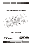
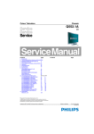
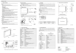
1
H.264 IP HD encoder
User Manual
V1.0
Contents
Chapter 1..................................................................................................................................................... 3
Introduction................................................................................................................................................. 3
overvie
w............................................................................................................................................. 3
1.1
1.1、overvie
overview
Features ………………………………………………………………………………
.......
……
...
3
1.2
1.2、Features
……………………………………………………………………………….......
.......……
……...
...3
1.3
1.3、
、 Performance index ...................................................................................................................... 3
Appearance and Description...................................................................................................... 4
1.4 、Appearance
Chapter 2 .................................................................................................................................................. 5
Installation guide.......................................................................................................................................5
Acquisition Check............................................................................................................................ 5
2.1
2.1、Acquisition
2.2
2.2、 Installation Preparation.............................................................................................................. 5
........................................6
2.2.1 Device
Device’’s Installation Flow Chart Illustrated as follows
follows:........................................6
..............................................................................................
2.2.2 Environment Requirement
Requirement:..............................................................................................
..............................................................................................66
...................................................................... 6
2.2.3 Grounding System design Requirements
Requirements......................................................................
.................................................................................................................
2.2.4 Cabinet Grounding
Grounding.................................................................................................................
.................................................................................................................77
...................................................................................................................
2.2.5 Device Grounding
Grounding...................................................................................................................
...................................................................................................................77
2.3
2.3、 The power wire Connection....................................................................................................... 7
2.4
2.4、 Input, output signal wire connection..................................................................................... 7
Chapter 3..................................................................................................................................................... 8
operation.......................................................................................................................................................8
The connection and use of device:............................................................................................ 8
3.1
3.1、The
Enter the WEB interface of the device
3.2 、E
device:............................................................................... 8
Enter the Home page interface of network management ………………………………
10
3.3
3.3、Enter
………………………………10
Enter status monitoring interface of the device :...................................................11
3.4
3.4、Enter
Enter the encoding parameter setting interface of the device :..........................11
3.5 、Enter
Enter the management interface of the device
...................................................13
3.6
3.6、Enter
device:...................................................13
Chapter 1 Introduction
、 overview
1.1
1.1、
The latest H.264 HD IP encoder which be published by our company, Support 1-8 channel HDMI
HD video source input, Supports H.264-HP, BP and other encoding modes, support simultaneous
multiple bit rate encoding, encoding delay is less than 200ms, output bit rate, resolution can be
customized, GOP length also can be customized.
Provide solutions for Based on Windows, Linux client receive audio and video, recording audio and
video, Convenient for storing live streams, Suitable for various occasions of needing Mobile live
Features
1.2
1.2、Features
※ 、 High-definition, low stream: using the most advanced encoding video compression standard
H.264-HP(High-Profile) 、 BP(Baseline Profile), to achieve high-definition signals, low bit rate
encoding transmission;
※、Support setting DHCP, PPPoE, set a fixed IP and other network access ways
※、interface support HDMI HD video source input,convenient for carry portable broadcast
applications;
※ Support video and audio bit rate adjustment, video support 3000kpbs to 8Mbps adjustable, video
support 64k、96k、128k、192k adjustable; Audio sampling rate support 44.1K, 48K adjustable
※、Support RTMP streaming media protocol, It can push live stream directly to many streaming
media servers, like Flash Media Server、Media Server、RED5 and so on, watched by variety
player(Flash Player, VLC、MX etc. )
※、System uses a high-performance DSP processing chip, higher coding efficiency and transmission
efficiency, Good real-time performance,Good video and audio synchronization, delay is less than
300ms
※、support a variety network protocol (TCP/IP、RTMP、HTTP)
※、Built-in Web Server, Easily achieved remote monitoring, control, set and other operations through
the IE browser
※、Support function of equipment remote security upgrade
※、High reliability design, stable operation, high performance and low cost;
※、1U Standard case unit,
1.3 、 Performance index
project
Signal Input Interface
index
Signal output interface
GOP structure
resolution
The default video
coding algorithm
1RJ45 100M network interface
adjustable
720P- 50、1080i-50、1080i-60
H.264 High Profile 5.0、BP(Baseline Profile)
Encoding mode
Automatically detects
resolution
Picture delay
protocol
Audio algorithms
Audio sampling rate
Audio bit rate
Bit rate
performance
Support CBR/VBR
Support
Embedded WEB
service
The maximum number
of user connections
Working temperature
Relative Humidity
weight
power
Power Consumption
size
HDMI ,1-8 routes HDMI audio and video input interface
(1/2/4/6/8 optional)
< 200ms(LAN)
Support IP/TCP、RTMP、HTTP etc
AAC
44.1K、48K adjustable
64K 96k、128K、192K adjustable
3000kpbs-8Mbps adjustable
The maximum output frame rate is 30fps,the minimum
bandwidth is 32Kbps
Support IE browser, Firefox, Maxthon, Opera
browse,configure, upgrade
1
-20~45℃
5~95%
1.5kg
AC110V~240V-50/60Hz
< 30W
1UStandard case
Appearance and Description
1.4 、Appearance
HD IP Encoder Front Panel:
1: the power indicator;
2-9:1-8channels lock Indicator light,light up lock light when the video source input normally.
HD IP Encoder Rear Panel
Panel::
1、Encoding 1-8 channels IP output interface/ network management port。
2、Reset button。
3、4、5、6、7、8、9、10Encoding 1-8 channels HDMI Video/Audio input interface。
11、power switch。12:Fuse。13:Power Jack。14:Ground terminal。
Chapter 2 Installation guide
Acquisition Check
2.1
2.1、Acquisition
When users open the package of the device,it is necessary to check the packaging materials of
widgets,check items in the package according to packing list or the following items:
• Encoder
1
• User Manual
1
• AC input power plug wire
1
If any item is missing or mismatches with the list above,Please contact the company immediately
2.2
2.2、 Installation Preparation
When users install the device, please follow the following steps.The details of installation will be
described at the rest part of this chapter,Users also can refer to the rear panel chart,This chapter mainly
includes the following content
� Checking the possible device missing or damage during the transportation
� Preparing relevant environment for installation
� Installing Encoder
� Connecting signal wires
� Connecting communication port (optional)
2.2.1 Device
Device’’s Installation Flow Chart Illustrated as follows
follows:
Connecting
Acquisition
Fixing
Grouding
Connecting
Setting
Running
Check
Device
Wire and
Signal
Parameter
Device
Power
Wire
Cord
2.2.2 Environment Requirement
Items
Requirement
When the devices are installed in several rows in the device
Installation
space
room, their distance should be between 1.2~1.5m, and the
distance to the wall should be no less than 0.8m.
No conduction, and no dusting.
Floor of the
equipment room
Mass resistivity of the antistatic flooring:1×10⁷~1×10¹⁰ Ω.
Grounding current limiting resistance: 1MΩ
Floor bearing: more than 450Kg/m2
Environment
5~40℃ (sustainable); 0~45℃ (short term).The air conditioner is
Temperature
recommended to install.
Relative
temperature
Pressure
20%~80% sustainable, 10%~90% short time.
86~105KPa。
They must be sealed with
Window&door
dustproof ruber strip. And the
windows should be installed with double glass and sealed
strictly.
Wall paper can be pasted,and flat paint can be used, but
Wall
Fire prevention
powdered paint isn’t applicable.
fire alarm system and extinguisher.
It requires three sets of separate power supply system :device
Power supply
power, air-conditioner power and lighting power. device power provided
by AC power.
2.2.3 Grounding System design Requirements
Each function modules’good grounding designs will guarantee reliable and stable operation of the
Device,Also guarantee against lightning, anti-interference.Therefore, the system grounding must
follow this rule.
� outer conductor of coaxial cable and both ends of shielding layer should keep good electrical
contact with surface of the metal chassis of connected devices
� Grounding conductor must use copper conductor to reduce the high frequency
impedance,grounding wire must be as thick and short as possible
� Both ends of the ground wire connection point should confirm the electrical contact is good,and
should be done anticorrosive processing;
� Prohibit useing the other equipment as the part of the ground wire's electrical connection;
� Conductor cross-sectional area between Cabinet and grounding wire of lightning protection
should be equal or greater than 25mm2
2.2.4 Cabinet Grounding
�
Grounding terminal of each cabinet in same room should be separately connected to protected
copper platoon ,The grounding wire should be as short as possible ,If the wiring is too long when
the project installed,should be cut off to avoid grounding wire circling,Conductor cross-sectional
area between Ground terminal and ground platoon should be equal or greater than 25mm2.
2.2.5 Device Grounding
Connect protective grounding terminal to protective grounding wire of assembly cabinet with wire
2.3
2.3、 The power wire Connection
Power jack located in left side of the rear panel,Next to the power socket. is the power switch,Under
the left of the power socket is the connective screw of protective grounding wire
● Connect the power wire:
Insert one end of the power wire into AC power socket,and another end connected to AC power.
● Connect the grounding wire:
When the device connects separately to protective ground, it should adopt independent grounding
way,That is, grounded together with other devices (such as transmission equipment), Grounding
resistance of Joint Ground is less than 1Ω.
�Caution:
Before connecting the power wire,encoder power switch must be placed in "OFF" position.And
requires grounded together with the power supply system
2.4
2.4、 Input, output signal wire connection
Signal wire connections include connection of output and input signal wire,signal wire of input
HDMI high-definition connected with HDMI high-definition interface of encoder, the other end
connect with the output interface of the front-end source equipment .The output of HD encoder has
1RJ45 IP network port,It can connected to the device of transmission network With network wire.
Important note: the HDMI source requirements which input by HDMI HD encoder
HDMI1.3 standard, frequency stability reached 5 ‰.
meet HDMI1.1,
Chapter 3 operation
HD Encoder adopt embedded WEB Service,In computer multiple browsers (support IE browser
Firefox, Maxthon, Opera browse) interface, set each parameter, system maintenance and upgrade set,
the default Settings of device can be used before the normal business, also can modify or reconfigured
the device parameter Settings.
The connection and use of device:
3.1
3.1、The
Connect the device as figure below,The device is IP encoder of 1-8 channel user optional,Here
described a case of a 8-channel encoder,If encoder is single channel, 2、4、6channels encoder,Please
connect according to the actual situation.
CAT5
Switch
PC
Server or IP
network
HDMI
A/V cable
8-1 channel
HDMIA/V source
After Connected, Turn on the power of the all device, use default set parameters of the device ,The
analog signal compression coding for digital IP signal enter the network transmission.
Enter the WEB interface of the device
3.2 、Enter
After Connected, Turn on the power of the all device,select any browser on computer,such as IE
browser Firefox, Maxthon, Opera browse,Enter in the browser address bar:http://192.168.1.100/
Complete IP address,(Note: The default IP address 100 is encoded 1-channel,101 is encoded
2-channel,102 is encoded 3-channel,103 is encoded 4-channel,104 is encoded 5-channel;105 is
encoded 6-channel;106 is encoded 7-channel;107 is encoded 8-channel),Click the search button to
enter the following interface,(the following part 1 #- 8# encoding channel network management
interface are the same) :
Figure 1 English interface
3.3
3.3、 Enter the Home page interface of network management :
Type admin in the "User Name " bar box and “pwss”bar box, Click "Login" button to enter device
network management interface.Click on the left sidebar of the first option " Home " , Can provide
device information of IP encoder as shown in figure 2 below
Figure 2 English interface
Enter status monitoring interface of the device
3.4
3.4、Enter
In the above conditions, click"Monitor" (status Monitoring) button to enter the status monitoring
interface of the device. As is shown in figure 3 , can provides status information of input source lock
instruction, input resolution; client connection status; client information .
Figure 3 English interface
3.5
Enter the encoding parameter setting interface of the device
3.5、Enter
device:
In the above conditions, click "Encode Settings" button enter the encoding parameter setting interface
of the device. As shown in Figure 4.
Figure 4 English interface
Output Settings include: output protocol, RTMP, HTTP optional; Port number can be modified;
Broadcast address, fixed, http://192.168.1.249:8000/ive; Video encoding settings include:
video input channels, fixed HDMI; encoding format, H.264, input resolution, 1920 * 1080 50i;
video GOP, 30; CBR / VBR, VBR optional; average bit rate, 5000Kbps; bit rate upper limit ,
8000Kbps; bit rate lower limit, 4000Kbps; Audio encoding Settings include: audio compressed
format, AAC; Sound mode, Stereo; The audio sampling rate, 48 K / 44.1 K optional; The audio
bit rate, 96 k, 64 k / 96 k / 128 k / 192 k optional.
Enter the management interface of the device
3.6
3.6、Enter
In the above conditions, click "Device Management"button to enter management interface of the
device. As shown in figure 5. Click "IP Encoder" button on the left, to provide basic information of
device (modules).
Figure 5 English interface
Click the "System Settings" button on the left, enter the following interface in Figure 6,
which provides parameter import / export and operation interface of upgrade system.
Figure 6 English interface
Click "Device reboot Settings" button on the left, enter the following interface in Figure 7 , which
provides operation interface of device reboot , click "Restart" button to reboot the device.
Figure 7 English interface
Click on the "device restore factory Settings" button on the left, enter the following interface in
Figure 8, which provide operation interface of restore factory setting, click the " reset " button to
complete device restore factory Settings (if you don't know how to configure the device, please use
this option with caution).
Figure 8 English interface
Click "Device Network params Edit" button on the left, enter the following interface in Figure 9,
which provide operation interface of device network parameters modified (network address,
gateway address, subnet mask), after modified the network parameter, click the "Apply" button
to complete modified the device network params.
Figure 9 English interface
Click "User Management" button on the left, enter the following interface in Figure 10,which
provides user management operation interface (existing user name 、existing password, new
username 、new password), after modified the user management information, click "Edit" button to
complete modified the user management information.
Figure 10 English interface
Caution
Caution:Please do not cut off the power of the encoder during upgrading ,it will restart
automatically after upgrading be finished(Process needs 3 minutes)
when restart,
Important note: if it
it’’s IP encoder , needs to turning off the power switch,
switch,when
please turn off the power switch, wait 1 5 minutes and then turn on the power switch.